US8699175B1 - Disk drive mapping low frequency write addresses to circular buffer write zone - Google Patents
Disk drive mapping low frequency write addresses to circular buffer write zone Download PDFInfo
- Publication number
- US8699175B1 US8699175B1 US13/554,994 US201213554994A US8699175B1 US 8699175 B1 US8699175 B1 US 8699175B1 US 201213554994 A US201213554994 A US 201213554994A US 8699175 B1 US8699175 B1 US 8699175B1
- Authority
- US
- United States
- Prior art keywords
- data
- write
- frequency
- lbas
- shingled
- Prior art date
- Legal status (The legal status is an assumption and is not a legal conclusion. Google has not performed a legal analysis and makes no representation as to the accuracy of the status listed.)
- Active, expires
Links
- 238000013507 mapping Methods 0.000 title description 4
- 238000000034 method Methods 0.000 claims description 11
- 238000010586 diagram Methods 0.000 description 6
- 230000002950 deficient Effects 0.000 description 3
- 239000004065 semiconductor Substances 0.000 description 2
- 230000003116 impacting effect Effects 0.000 description 1
- 230000002452 interceptive effect Effects 0.000 description 1
- 238000004519 manufacturing process Methods 0.000 description 1
- 230000000737 periodic effect Effects 0.000 description 1
- 230000003068 static effect Effects 0.000 description 1
- 230000007704 transition Effects 0.000 description 1
Images


Classifications
-
- G—PHYSICS
- G11—INFORMATION STORAGE
- G11B—INFORMATION STORAGE BASED ON RELATIVE MOVEMENT BETWEEN RECORD CARRIER AND TRANSDUCER
- G11B5/00—Recording by magnetisation or demagnetisation of a record carrier; Reproducing by magnetic means; Record carriers therefor
- G11B5/012—Recording on, or reproducing or erasing from, magnetic disks
-
- G—PHYSICS
- G11—INFORMATION STORAGE
- G11B—INFORMATION STORAGE BASED ON RELATIVE MOVEMENT BETWEEN RECORD CARRIER AND TRANSDUCER
- G11B20/00—Signal processing not specific to the method of recording or reproducing; Circuits therefor
- G11B20/10—Digital recording or reproducing
- G11B20/12—Formatting, e.g. arrangement of data block or words on the record carriers
- G11B20/1217—Formatting, e.g. arrangement of data block or words on the record carriers on discs
Definitions
- Disk drives comprise a disk and a head connected to a distal end of an actuator arm which is rotated about a pivot by a voice coil motor (VCM) to position the head radially over the disk.
- VCM voice coil motor
- the disk comprises a plurality of radially spaced, concentric tracks for recording user data sectors and servo sectors.
- the servo sectors comprise head positioning information (e.g., a track address) which is read by the head and processed by a servo control system to control the actuator arm as it seeks from track to track.
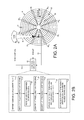
- FIG. 1 shows a prior art disk format 2 comprising a plurality of servo tracks 4 defined by a number of servo sectors 6 O - 6 N , wherein data tracks are defined relative to the servo tracks 4 .
- Each servo sector 6 comprises a preamble 8 for storing a periodic pattern, which allows proper gain adjustment and timing synchronization of the read signal, and a sync mark 10 for storing a special pattern used to symbol synchronize to a servo data field 12 .
- the servo data field 12 stores coarse head positioning information, such as a track address, used to position the head over a target data track during a seek operation.
- Each servo sector 6 further comprises groups of servo bursts 14 (e.g., A, B, C and D bursts), which comprise a number of consecutive transitions recorded at precise intervals and offsets with respect to a servo track centerline.
- the groups of servo bursts 14 provide fine head position information used for centerline tracking while accessing a data track during write/read operations.
- the data sectors are accessed indirectly using logical block addresses (LBAs) mapped to physical block addresses (PBAs) representing the physical location of each data sector.
- LBAs logical block addresses
- PBAs physical block addresses
- This indirect accessing facilitates mapping out defective data sectors during manufacturing as well as while the disk drive is deployed in the field.
- Access commands (read/write) received from the host include LBAs which the disk drive maps to corresponding PBAs using any suitable mapping technique.
- FIG. 1 shows a prior art disk format comprising a plurality of servo tracks defined by servo sectors.
- FIG. 2A shows a disk drive according to an embodiment of the present invention comprising a head actuated over a disk.
- FIG. 2B is a flow diagram according to an embodiment of the present invention wherein data associated with frequently written LBAs is stored in a random access write zone, and data associated with infrequently written LBAs is stored in a circular buffer write zone.
- FIG. 3A shows an embodiment of the present invention wherein the random access write zone comprises non-shingled data tracks, and the circular buffer write zone comprises shingled data tracks.
- FIG. 3B illustrates shingled data tracks that achieve a higher radial density according to an embodiment of the present invention.
- FIG. 4 shows a disk format comprising a first circular buffer write zone for storing first frequency write LBAs, a random access write zone for storing second frequency write LBAs, and a second circular buffer write zone for storing third frequency write LBAs according to an embodiment of the present invention.
- FIG. 5 is a flow diagram according to an embodiment of the present invention wherein when writing data to shingled data tracks of the circular buffer write zone, the previously written data track is read and then verified after being overwritten.
- FIG. 2A shows a disk drive according to an embodiment of the present invention comprising a head 15 actuated over a disk 16 comprising a plurality of data tracks 17 .
- the disk drive further comprises control circuitry 18 operable to execute the flow diagram of FIG. 2B , wherein a random access write zone 20 is defined on the disk comprising a first plurality of the data tracks (block 21 ), and a circular buffer write zone 22 is defined on the disk comprising a second plurality of the data tracks (block 24 ).
- Write commands are received comprising logical block addresses (LBAs) (block 26 ).
- First frequency write LBAs are identified (block 28 ), and second frequency write LBAs are identified (block 30 ), where the second frequency is higher than the first frequency.
- Data associated with the first frequency write LBAs is stored in the circular buffer write zone (block 32 ), and data associated with the second frequency write LBAs is stored in the random access write zone (block 34 ).
- the plurality of data tracks 17 are defined relative to servo sectors 36 O - 36 N recorded on the disk 16 .
- the control circuitry 18 processes a read signal 38 emanating from the head 15 to demodulate the servo sectors 36 O - 36 N and generate a position error signal (PES) representing an error between the actual position of the head and a target position relative to a target track.
- PES position error signal
- the control circuitry 18 filters the PES using suitable compensation filters to generate a control signal 40 applied to a voice coil motor (VCM) 42 which rotates an actuator arm 44 about a pivot, thereby actuating the head 15 radially over the disk 16 in a direction that reduces the PES.
- VCM voice coil motor
- the servo sectors 36 O - 36 N may comprise any suitable position information, such as a track and wedge address for coarse positioning and servo bursts for fine positioning as described above with reference to FIG. 1 .
- the servo bursts may comprise any suitable pattern, such as an amplitude based servo pattern as shown in FIG. 1 , or a suitable phase based servo pattern.
- the control circuitry 18 maps LBAs to the PBAs of data sectors in the random access write zone 20 shown in FIG. 2A using static allocation such that when an LBA is overwritten, the data is written to the same PBA (unless the PBA becomes defective in which case the LBA is mapped to a spare PBA).
- the control circuitry 18 maps LBAs to the PBAs of data sectors in the circular buffer write zone 22 using dynamic allocation such that when an LBA is overwritten, the data is written to the PBA at the head of the circular buffer rather than to the previously mapped PBA (the previously mapped PBA is marked as invalid).
- the data stored in valid PBAs at the tail of the circular buffer are relocated to the PBAs at the head of the circular buffer, thereby freeing space at the tail of the circular buffer.
- the head of the circular buffer wraps around to the tail so that the previously written (and garbage collected) data tracks can be overwritten.
- the data tracks in the circular buffer write zone 22 are shingled by writing the data tracks in an overlapping manner. Overlapping the data tracks increases the radial density of the shingled data tracks, thereby increasing the capacity of the disk drive.
- the shingled data tracks are written as a circular buffer as illustrated in FIG. 3A , wherein the data tracks are written from the inner diameter toward the outer diameter (or vice versa), and a newly written data track partially overwrites the previously written data track as illustrated in FIG. 3B .
- the writing begins again by overwriting the first data track at the inner diameter, and then continuing to write toward the outer diameter.
- frequently written LBAs are written to the non-shingled data tracks of the random access write zone 20 and infrequently written LBAs are written to the shingled data tracks of the circular buffer write zone 22 .
- This increases the overall capacity of the disk drive since the radial density of the shingled data tracks may be significantly higher than the radial density of the non-shingled data tracks.
- the performance of the disk drive is not impacted significantly by the garbage collection performed on the circular buffer write zone 22 since the frequency of writes is low. That is, the garbage collection can be executed infrequently between long intervals, or the garbage collection can be executed continuously with frequent interruptions in order to service host access commands. Since the frequency of writes to the circular buffer write zone 22 is low, the garbage collection is able to maintain adequate free space in the circular buffer for future write commands without interfering with the throughput of the host access commands.
- the lower radial density of the data tracks in the random access write zone 20 may increase performance by avoiding (or reducing) the need to perform write verify operations, whereas the higher radial density of the shingled data tracks in the circular buffer write zone 22 may reduce performance due to a need to perform write verify operations.
- Storing data associated with infrequently written LBAs in the shingled data tracks of the circular buffer write zone 22 reduces the frequency of corresponding write verify operations while increasing the overall capacity of the disk drive.
- FIG. 4 shows another embodiment of the present invention wherein the disk 16 comprises a first circular buffer write zone 22 and a second circular buffer write zone 46 .
- the data tracks in the second circular buffer write zone 46 are recorded at a low enough radial density (shingled or non-shingled) to avoid (or reduce) the need to perform write verify operations.
- the data associated with high frequency write LBAs may be stored in the random access write zone 20 , the data associated with low frequency write LBAs stored in the first circular buffer write zone 22 , and the data associated with medium frequency write LBAs stored in the second circular buffer write zone 46 .
- the frequency of writes to both the first and second circular buffer write zones 22 and 46 is low enough so that the resulting garbage collection does not significantly impact the performance of the disk drive.
- the frequency of writes to the first circular buffer write zone 22 is low enough to allow write verify operations without significantly impacting the performance of the disk drive.
- data associated with very high frequency write LBAs may be written to the second circular buffer write zone 46 shown in FIG. 4 , whereas data associated with very low frequency write LBAs may be stored in the first circular buffer write zone 22 , and data associated with medium frequency write LBAs stored in the random access write zone 20 .
- Writing very high frequency write LBAs to the second circular buffer write zone 46 may improve performance by avoiding the seek operations that would otherwise be required when writing to the random access write zone 20 .
- the LBAs assigned to the second circular buffer write zone 46 are written with a high frequency, the amount of valid data sectors needing to be relocated during the garbage collection operation is minimal. That is, most of the data sectors in the older data tracks will eventually become invalid due to the corresponding LBAs being overwritten, and therefore there will be very few data sectors that need relocating to the head of the circular buffer during the garbage collection operation.
- the radial density of the data tracks in the second circular buffer write zone 46 is selected low enough to avoid (or reduce) the need to perform write verify operations, whereas a high radial density (e.g., shingled) is selected for the first circular buffer write zone 22 to increase the capacity of the disk drive. Since the first circular buffer write zone 22 is used to store data associated with infrequently written LBAs, the frequency of write verify operations performed on the first circular buffer write zone 22 is reduced and therefore does not significantly impact the performance of the disk drive.
- FIG. 5 is a flow diagram according to an embodiment of the present invention wherein when a write command is received, the LBA(s) is evaluated (block 48 ). If the LBA of the write command is a frequently written LBA, the data is written to the random access write zone 20 without performing a write verify operation (block 50 ). If the LBA of the write command is an infrequently written LBA (bock 48 ), the data is written to a shingled data track of the circular buffer write zone 22 . Prior to overwriting a first shingled data track with the write data of the write command, the first shingled data track is read and the read data buffered (block 52 ).
- the write data is then written to a second shingled data track which overwrites at least part of the first shingled track (block 54 ).
- An optional write verify operation is executed on the second shingled data track to verify the recoverability of the written data (block 56 ). If the second shingled data track does not pass the write verify operation (block 58 ), the write data is again written to the second shingled data track until passing the write verify operation. After passing the write verify operation, the first (overwritten) shingled data track is read to verify recoverability (block 60 ). If the first shingled data track does not pass the read verify (block 62 ), the buffered data read from the first shingled data track (at block 52 ) is written to a shingled data track (block 64 ).
- the buffered data read from the first shingled data track may be written to the next shingled data track at the head of the circular buffer after skipping a data track so that the second shingled data track is not overwritten.
- This embodiment leaves two blank data tracks on each side of the second shingled data track that are eventually recovered during the garbage collection operation.
- the first (overwritten) data track fails the read verify operation a predetermined number of times, it may be mapped out as defective.
- the mapping of LBAs based on the frequency of writes may change over time based on any suitable metric, such as a performance metric or a capacity metric.
- a performance metric such as a performance metric or a capacity metric.
- the number of LBAs mapped to either the random access write zone 20 or the circular buffer write zone 22 may vary over time based on the free space available in either storage area. If the free space in the random access write zone 20 falls below a predetermined threshold, the threshold for discriminating between the high/low frequency write LBAs may be adjusted so that more of the LBAs are mapped to the circular buffer write zone 22 when servicing write commands. Conversely, more of the LBAs may be mapped to the random access write zone 20 if the free space in the circular buffer write zone 22 falls below a predetermined threshold.
- data may be migrated between the two write zones during a background operation (and the LBAs remapped) in order to better balance the free space of the two write zones.
- a performance metric of the disk drive may be monitored, such as by measuring an average throughput of host access commands serviced by the disk drive. If the performance metric degrades below a threshold due to an excessive number of garbage collection and/or write verify operations performed on the circular buffer write zone 22 , the threshold for discriminating between the high/low frequency write LBAs may be adjusted so that more of the LBAs are mapped to the random access write zone 20 . Conversely, more of the LBAs may be mapped to the circular buffer write zone 22 if the performance metric rises above a predetermined threshold.
- control circuitry may be implemented within a read channel integrated circuit, or in a component separate from the read channel, such as a disk controller, or certain operations described above may be performed by a read channel and others by a disk controller.
- the read channel and disk controller are implemented as separate integrated circuits, and in an alternative embodiment they are fabricated into a single integrated circuit or system on a chip (SOC).
- the control circuitry may include a suitable preamp circuit implemented as a separate integrated circuit, integrated into the read channel or disk controller circuit, or integrated into a SOC.
- control circuitry comprises a microprocessor executing instructions, the instructions being operable to cause the microprocessor to perform the flow diagrams described herein.
- the instructions may be stored in any computer-readable medium. In one embodiment, they may be stored on a non-volatile semiconductor memory external to the microprocessor, or integrated with the microprocessor in a SOC. In another embodiment, the instructions are stored on the disk and read into a volatile semiconductor memory when the disk drive is powered on. In yet another embodiment, the control circuitry comprises suitable logic circuitry, such as state machine circuitry.
Abstract
Description
Claims (16)
Priority Applications (1)
| Application Number | Priority Date | Filing Date | Title |
|---|---|---|---|
| US13/554,994 US8699175B1 (en) | 2012-07-20 | 2012-07-20 | Disk drive mapping low frequency write addresses to circular buffer write zone |
Applications Claiming Priority (1)
| Application Number | Priority Date | Filing Date | Title |
|---|---|---|---|
| US13/554,994 US8699175B1 (en) | 2012-07-20 | 2012-07-20 | Disk drive mapping low frequency write addresses to circular buffer write zone |
Publications (1)
| Publication Number | Publication Date |
|---|---|
| US8699175B1 true US8699175B1 (en) | 2014-04-15 |
Family
ID=50441464
Family Applications (1)
| Application Number | Title | Priority Date | Filing Date |
|---|---|---|---|
| US13/554,994 Active 2032-10-03 US8699175B1 (en) | 2012-07-20 | 2012-07-20 | Disk drive mapping low frequency write addresses to circular buffer write zone |
Country Status (1)
| Country | Link |
|---|---|
| US (1) | US8699175B1 (en) |
Cited By (71)
| Publication number | Priority date | Publication date | Assignee | Title |
|---|---|---|---|---|
| US20140019680A1 (en) * | 2012-07-16 | 2014-01-16 | Agency For Science, Technology And Research | Data storage system, method of writing to storage in the data storage system, hard disk and method of forming the hard disk |
| US20140115238A1 (en) * | 2012-10-18 | 2014-04-24 | Agency For Science, Technology And Research | Storage controllers and storage control methods |
| US20140254042A1 (en) * | 2013-03-07 | 2014-09-11 | Seagate Technology Llc | Dynamic allocation of lba to un-shingled media partition |
| US8879188B1 (en) | 2010-08-23 | 2014-11-04 | Western Digital Technologies, Inc. | Disk drive employing fly height calibration tracks to account for magnetic entropy and thermal decay |
| US8902529B1 (en) | 2012-11-20 | 2014-12-02 | Western Digital Technologies, Inc. | Dual frequency crystal oscillator |
| US8902527B1 (en) | 2010-03-22 | 2014-12-02 | Western Digital Technologies, Inc. | Systems and methods for improving sequential data rate performance using sorted data zones |
| US8909889B1 (en) | 2011-10-10 | 2014-12-09 | Western Digital Technologies, Inc. | Method and apparatus for servicing host commands by a disk drive |
| US8914625B1 (en) | 2009-07-31 | 2014-12-16 | Western Digital Technologies, Inc. | Automatically configuring a web browser file when booting an operating system from a data storage device |
| US8937782B1 (en) | 2012-05-07 | 2015-01-20 | Western Digital Technologies, Inc. | Hard disk drive assembly including a NVSM to store configuration data for controlling disk drive operations |
| US8953269B1 (en) | 2014-07-18 | 2015-02-10 | Western Digital Technologies, Inc. | Management of data objects in a data object zone |
| US8954664B1 (en) | 2010-10-01 | 2015-02-10 | Western Digital Technologies, Inc. | Writing metadata files on a disk |
| US8959281B1 (en) | 2012-11-09 | 2015-02-17 | Western Digital Technologies, Inc. | Data management for a storage device |
| US8990493B1 (en) | 2011-06-30 | 2015-03-24 | Western Digital Technologies, Inc. | Method and apparatus for performing force unit access writes on a disk |
| US8996839B1 (en) | 2012-01-23 | 2015-03-31 | Western Digital Technologies, Inc. | Data storage device aligning partition to boundary of sector when partition offset correlates with offset of write commands |
| US9009358B1 (en) | 2008-09-23 | 2015-04-14 | Western Digital Technologies, Inc. | Configuring a data storage device with a parameter file interlocked with configuration code |
| US20150109700A1 (en) * | 2013-10-18 | 2015-04-23 | HGST Netherlands B.V. | Shingled magnetic recording system with adaptive write buffer area |
| US9025270B1 (en) | 2013-09-17 | 2015-05-05 | Western Digital Technologies, Inc. | Electronic system with current conservation mechanism and method of operation thereof |
| US20150135005A1 (en) * | 2013-11-13 | 2015-05-14 | Dell Products, Lp | Efficient Incremental Updates for Shingled Magnetic Recording (SMR) Drives in a RAID Configuration |
| US9047923B1 (en) * | 2014-06-18 | 2015-06-02 | Seagate Technology Llc | Fast shingled tracks recording |
| US9049471B2 (en) | 2001-10-17 | 2015-06-02 | Keen Personal Media, Inc. | Personal video recorder for inserting a stored advertisement into a displayed broadcast stream |
| US9060420B2 (en) | 2007-11-01 | 2015-06-16 | Western Digitial Technologies, Inc. | Method of manufacturing a double sided flex circuit for a disk drive wherein a first side lead provides an etching mask for a second side lead |
| US9064504B1 (en) | 2014-01-29 | 2015-06-23 | Western Digital Technologies, Inc. | Electronic system with media recovery mechanism and method of operation thereof |
| US9063838B1 (en) | 2012-01-23 | 2015-06-23 | Western Digital Technologies, Inc. | Data storage device shifting data chunks of alignment zone relative to sector boundaries |
| US9075714B1 (en) | 2014-05-13 | 2015-07-07 | Western Digital Technologies, Inc. | Electronic system with data management mechanism and method of operation thereof |
| US9123382B1 (en) | 2014-10-28 | 2015-09-01 | Western Digital Technologies, Inc. | Non-volatile caching for sequence of data |
| US9128820B1 (en) | 2012-06-18 | 2015-09-08 | Western Digital Technologies, Inc. | File management among different zones of storage media |
| US9129628B1 (en) | 2014-10-23 | 2015-09-08 | Western Digital Technologies, Inc. | Data management for data storage device with different track density regions |
| US9135205B1 (en) | 2013-05-01 | 2015-09-15 | Western Digital Technologies, Inc. | Data storage assembly for archive cold storage |
| US9153287B1 (en) | 2013-05-13 | 2015-10-06 | Western Digital Technologies, Inc. | Data access for shingled magnetic recording media |
| US9158722B1 (en) | 2011-11-02 | 2015-10-13 | Western Digital Technologies, Inc. | Data storage device to communicate with a host in a SATA or a USB mode |
| US9189392B1 (en) | 2011-06-30 | 2015-11-17 | Western Digital Technologies, Inc. | Opportunistic defragmentation during garbage collection |
| US9196302B1 (en) | 2015-03-18 | 2015-11-24 | Western Digital Technologies, Inc. | Electronic system with media maintenance mechanism and method of operation thereof |
| US9236086B1 (en) | 2014-10-15 | 2016-01-12 | Western Digital Technologies, Inc. | Methods for reducing operational latency of data storage systems |
| US9245558B1 (en) | 2014-05-09 | 2016-01-26 | Western Digital Technologies, Inc. | Electronic system with data management mechanism and method of operation thereof |
| US9257143B1 (en) | 2014-12-23 | 2016-02-09 | Western Digital Technologies, Inc. | Precautionary measures for data storage device environmental conditions |
| US9263088B2 (en) | 2014-03-21 | 2016-02-16 | Western Digital Technologies, Inc. | Data management for a data storage device using a last resort zone |
| US9268649B1 (en) | 2011-06-23 | 2016-02-23 | Western Digital Technologies, Inc. | Disk drive with recent write streams list for data refresh determination |
| US9268499B1 (en) | 2010-08-13 | 2016-02-23 | Western Digital Technologies, Inc. | Hybrid drive migrating high workload data from disk to non-volatile semiconductor memory |
| US9269393B1 (en) | 2014-12-08 | 2016-02-23 | Western Digital Technologies, Inc. | Electronic system with data refresh mechanism and method of operation thereof |
| US9311939B1 (en) | 2014-12-23 | 2016-04-12 | Western Digital Technologies, Inc. | Write-through media caching |
| US9330715B1 (en) | 2010-03-22 | 2016-05-03 | Western Digital Technologies, Inc. | Mapping of shingled magnetic recording media |
| US9383923B1 (en) | 2012-10-18 | 2016-07-05 | Western Digital Technologies, Inc. | Write pointer management for a disk drive |
| US9424864B2 (en) | 2014-07-02 | 2016-08-23 | Western Digital Technologies, Inc. | Data management for a data storage device with zone relocation |
| US9437242B1 (en) | 2015-09-14 | 2016-09-06 | Western Digital Technologies, Inc. | Data storage device employing different frequency preambles in adjacent data tracks |
| US9466321B1 (en) | 2015-06-05 | 2016-10-11 | Western Digital Technologies, Inc. | Angular position tracking of data accesses to mitigate risk of data loss |
| US9466318B2 (en) | 2014-12-24 | 2016-10-11 | Western Digital Technologies, Inc. | Allowing fast data zone switches on data storage devices |
| US9501393B2 (en) | 2014-01-27 | 2016-11-22 | Western Digital Technologies, Inc. | Data storage system garbage collection based on at least one attribute |
| US9536563B1 (en) * | 2016-02-16 | 2017-01-03 | Seagate Technology Llc | Detecting shingled overwrite errors |
| US9588898B1 (en) | 2015-06-02 | 2017-03-07 | Western Digital Technologies, Inc. | Fullness control for media-based cache operating in a steady state |
| US9600205B1 (en) | 2014-09-22 | 2017-03-21 | Western Digital Technologies, Inc. | Power aware power safe write buffer |
| US9632711B1 (en) | 2014-04-07 | 2017-04-25 | Western Digital Technologies, Inc. | Processing flush requests by utilizing storage system write notifications |
| US9639287B1 (en) | 2015-06-29 | 2017-05-02 | Western Digital Technologies, Inc. | Write command reporting |
| US9645752B1 (en) | 2014-04-07 | 2017-05-09 | Western Digital Technologies, Inc. | Identification of data committed to non-volatile memory by use of notification commands |
| US9672107B1 (en) | 2015-02-11 | 2017-06-06 | Western Digital Technologies, Inc. | Data protection for a data storage device |
| US9842622B1 (en) | 2014-12-23 | 2017-12-12 | Western Digital Technologies, Inc. | Data storage device having improved read failure tolerance |
| US9864529B1 (en) | 2014-01-27 | 2018-01-09 | Western Digital Technologies, Inc. | Host compatibility for host managed storage media |
| US9870281B1 (en) | 2015-03-20 | 2018-01-16 | Western Digital Technologies, Inc. | Power loss mitigation for data storage device |
| US9875055B1 (en) | 2014-08-04 | 2018-01-23 | Western Digital Technologies, Inc. | Check-pointing of metadata |
| US9933955B1 (en) | 2015-03-05 | 2018-04-03 | Western Digital Technologies, Inc. | Power safe write buffer for data storage device |
| US9952950B1 (en) | 2014-09-08 | 2018-04-24 | Western Digital Technologies, Inc. | Data management in RAID environment |
| US9959052B1 (en) | 2015-09-17 | 2018-05-01 | Western Digital Technologies, Inc. | Media based cache for data storage device |
| US10282371B1 (en) | 2014-12-02 | 2019-05-07 | Western Digital Technologies, Inc. | Object storage device with probabilistic data structure |
| US10282096B1 (en) | 2014-12-17 | 2019-05-07 | Western Digital Technologies, Inc. | Identification of data with predetermined data pattern |
| US10366726B1 (en) | 2018-03-29 | 2019-07-30 | Seagate Technology Llc | Interlaced magnetic recording in with multiple independent-actuators having respective independent heads |
| US10365836B1 (en) | 2015-01-27 | 2019-07-30 | Western Digital Technologies, Inc. | Electronic system with declustered data protection by parity based on reliability and method of operation thereof |
| US10424334B1 (en) * | 2019-01-08 | 2019-09-24 | Western Digital Technologies, Inc. | Data storage device formatting a disk surface with a write format and a read format |
| US10431246B2 (en) | 2016-12-15 | 2019-10-01 | Seagate Technology Llc | Dual actuator storage device utilizing multiple disk zones |
| US10510373B1 (en) * | 2018-03-29 | 2019-12-17 | Seagate Technology Llc | Multiple-actuator drive with separate, radially-defined, zones having reduced skew and/or different track properties |
| US10991387B1 (en) | 2020-03-27 | 2021-04-27 | Western Digital Technologies, Inc. | Data storage device migrating data from non-energy assist disk surface to energy assist disk surface |
| US11061595B2 (en) * | 2019-05-10 | 2021-07-13 | Seagate Technology Llc | Logical address remapping for direct write |
| US11074937B1 (en) * | 2020-03-17 | 2021-07-27 | Kabushiki Kaisha Toshiba | Magnetic disk device and depop processing method |
Citations (22)
| Publication number | Priority date | Publication date | Assignee | Title |
|---|---|---|---|---|
| US20020186492A1 (en) * | 2001-05-14 | 2002-12-12 | International Business Machines Corporation | Radial positioning of data to improve hard disk drive reliability |
| US20050069298A1 (en) | 2003-09-29 | 2005-03-31 | Hitachi Global Storage Technologies | System and method for writing data to HDD in bands |
| US20050248867A1 (en) * | 2004-05-07 | 2005-11-10 | Samsung Electronics Co., Ltd. | Method, apparatus, and medium for determining read and write frequencies in data storing systems and a disk drive using the same |
| US20060253621A1 (en) | 2005-05-04 | 2006-11-09 | Brewer Michael A | Quality of service for data storage volumes |
| US20070186029A1 (en) | 2006-01-04 | 2007-08-09 | Hitachi Global Storage Netherlands B.V. | Address assigning method, disk drive, and data writing method |
| US20070223132A1 (en) | 2006-03-24 | 2007-09-27 | Hitachi Global Storage Technologies Netherlands B.V. | Information recording apparatus |
| US7392340B1 (en) * | 2005-03-21 | 2008-06-24 | Western Digital Technologies, Inc. | Disk drive employing stream detection engine to enhance cache management policy |
| US20080239552A1 (en) * | 2007-03-30 | 2008-10-02 | Kabushiki Kaisha Toshiba | Information processing apparatus |
| US7549021B2 (en) * | 2006-02-22 | 2009-06-16 | Seagate Technology Llc | Enhanced data integrity using parallel volatile and non-volatile transfer buffers |
| US20090259819A1 (en) * | 2008-04-09 | 2009-10-15 | Skymedi Corporation | Method of wear leveling for non-volatile memory |
| US7617358B1 (en) * | 2005-05-05 | 2009-11-10 | Seagate Technology, Llc | Methods and structure for writing lead-in sequences for head stability in a dynamically mapped mass storage device |
| US7620772B1 (en) | 2005-05-05 | 2009-11-17 | Seagate Technology, Llc | Methods and structure for dynamic data density in a dynamically mapped mass storage device |
| US7653847B1 (en) * | 2005-05-05 | 2010-01-26 | Seagate Technology Llc | Methods and structure for field flawscan in a dynamically mapped mass storage device |
| US20100030987A1 (en) * | 2008-07-30 | 2010-02-04 | Samsung Electronics Co., Ltd | Data storing location managing method and data storage system |
| US7685360B1 (en) * | 2005-05-05 | 2010-03-23 | Seagate Technology Llc | Methods and structure for dynamic appended metadata in a dynamically mapped mass storage device |
| US7864476B2 (en) | 2008-03-20 | 2011-01-04 | Kabushiki Kaisha Toshiba | Low track-per-inch (TPI) zone with reduced need for adjacent-track-erasure (ATE) refresh |
| US7982994B1 (en) | 2010-05-12 | 2011-07-19 | Seagate Technology, Llc | Multi-level recording on shingled coherent magnetic media |
| US8004785B1 (en) * | 2008-05-09 | 2011-08-23 | Western Digital Technologies, Inc. | Disk drive write verifying unformatted data sectors |
| US20110292538A1 (en) | 2010-05-31 | 2011-12-01 | Kabushiki Kaisha Toshiba | Recording medium controller and method thereof |
| US20110304939A1 (en) | 2010-06-14 | 2011-12-15 | Tdk Corporation | Magnetic recording device, magnetic recording method and magnetic recording medium for shingle write scheme |
| US20120303873A1 (en) * | 2011-05-24 | 2012-11-29 | Lau Nguyen | Method for storage devices to achieve low write amplification with low over provision |
| US20130145223A1 (en) * | 2011-12-06 | 2013-06-06 | Hitachi, Ltd. | Storage subsystem and method for controlling the same |
-
2012
- 2012-07-20 US US13/554,994 patent/US8699175B1/en active Active
Patent Citations (24)
| Publication number | Priority date | Publication date | Assignee | Title |
|---|---|---|---|---|
| US20020186492A1 (en) * | 2001-05-14 | 2002-12-12 | International Business Machines Corporation | Radial positioning of data to improve hard disk drive reliability |
| US20050069298A1 (en) | 2003-09-29 | 2005-03-31 | Hitachi Global Storage Technologies | System and method for writing data to HDD in bands |
| US20050248867A1 (en) * | 2004-05-07 | 2005-11-10 | Samsung Electronics Co., Ltd. | Method, apparatus, and medium for determining read and write frequencies in data storing systems and a disk drive using the same |
| US7392340B1 (en) * | 2005-03-21 | 2008-06-24 | Western Digital Technologies, Inc. | Disk drive employing stream detection engine to enhance cache management policy |
| US20060253621A1 (en) | 2005-05-04 | 2006-11-09 | Brewer Michael A | Quality of service for data storage volumes |
| US7620772B1 (en) | 2005-05-05 | 2009-11-17 | Seagate Technology, Llc | Methods and structure for dynamic data density in a dynamically mapped mass storage device |
| US7617358B1 (en) * | 2005-05-05 | 2009-11-10 | Seagate Technology, Llc | Methods and structure for writing lead-in sequences for head stability in a dynamically mapped mass storage device |
| US7653847B1 (en) * | 2005-05-05 | 2010-01-26 | Seagate Technology Llc | Methods and structure for field flawscan in a dynamically mapped mass storage device |
| US7685360B1 (en) * | 2005-05-05 | 2010-03-23 | Seagate Technology Llc | Methods and structure for dynamic appended metadata in a dynamically mapped mass storage device |
| US20070186029A1 (en) | 2006-01-04 | 2007-08-09 | Hitachi Global Storage Netherlands B.V. | Address assigning method, disk drive, and data writing method |
| US7747810B2 (en) | 2006-01-04 | 2010-06-29 | Hitachi Global Storage Technologies Netherlands B.V. | Address assigning method, disk drive, and data writing method |
| US7549021B2 (en) * | 2006-02-22 | 2009-06-16 | Seagate Technology Llc | Enhanced data integrity using parallel volatile and non-volatile transfer buffers |
| US7417821B2 (en) | 2006-03-24 | 2008-08-26 | Hitachi Global Storage Technnologies Netherlands B.V. | Information recording apparatus |
| US20070223132A1 (en) | 2006-03-24 | 2007-09-27 | Hitachi Global Storage Technologies Netherlands B.V. | Information recording apparatus |
| US20080239552A1 (en) * | 2007-03-30 | 2008-10-02 | Kabushiki Kaisha Toshiba | Information processing apparatus |
| US7864476B2 (en) | 2008-03-20 | 2011-01-04 | Kabushiki Kaisha Toshiba | Low track-per-inch (TPI) zone with reduced need for adjacent-track-erasure (ATE) refresh |
| US20090259819A1 (en) * | 2008-04-09 | 2009-10-15 | Skymedi Corporation | Method of wear leveling for non-volatile memory |
| US8004785B1 (en) * | 2008-05-09 | 2011-08-23 | Western Digital Technologies, Inc. | Disk drive write verifying unformatted data sectors |
| US20100030987A1 (en) * | 2008-07-30 | 2010-02-04 | Samsung Electronics Co., Ltd | Data storing location managing method and data storage system |
| US7982994B1 (en) | 2010-05-12 | 2011-07-19 | Seagate Technology, Llc | Multi-level recording on shingled coherent magnetic media |
| US20110292538A1 (en) | 2010-05-31 | 2011-12-01 | Kabushiki Kaisha Toshiba | Recording medium controller and method thereof |
| US20110304939A1 (en) | 2010-06-14 | 2011-12-15 | Tdk Corporation | Magnetic recording device, magnetic recording method and magnetic recording medium for shingle write scheme |
| US20120303873A1 (en) * | 2011-05-24 | 2012-11-29 | Lau Nguyen | Method for storage devices to achieve low write amplification with low over provision |
| US20130145223A1 (en) * | 2011-12-06 | 2013-06-06 | Hitachi, Ltd. | Storage subsystem and method for controlling the same |
Cited By (80)
| Publication number | Priority date | Publication date | Assignee | Title |
|---|---|---|---|---|
| US9049471B2 (en) | 2001-10-17 | 2015-06-02 | Keen Personal Media, Inc. | Personal video recorder for inserting a stored advertisement into a displayed broadcast stream |
| US9060420B2 (en) | 2007-11-01 | 2015-06-16 | Western Digitial Technologies, Inc. | Method of manufacturing a double sided flex circuit for a disk drive wherein a first side lead provides an etching mask for a second side lead |
| US9009358B1 (en) | 2008-09-23 | 2015-04-14 | Western Digital Technologies, Inc. | Configuring a data storage device with a parameter file interlocked with configuration code |
| US8914625B1 (en) | 2009-07-31 | 2014-12-16 | Western Digital Technologies, Inc. | Automatically configuring a web browser file when booting an operating system from a data storage device |
| US8902527B1 (en) | 2010-03-22 | 2014-12-02 | Western Digital Technologies, Inc. | Systems and methods for improving sequential data rate performance using sorted data zones |
| US9330715B1 (en) | 2010-03-22 | 2016-05-03 | Western Digital Technologies, Inc. | Mapping of shingled magnetic recording media |
| US9268499B1 (en) | 2010-08-13 | 2016-02-23 | Western Digital Technologies, Inc. | Hybrid drive migrating high workload data from disk to non-volatile semiconductor memory |
| US8879188B1 (en) | 2010-08-23 | 2014-11-04 | Western Digital Technologies, Inc. | Disk drive employing fly height calibration tracks to account for magnetic entropy and thermal decay |
| US8954664B1 (en) | 2010-10-01 | 2015-02-10 | Western Digital Technologies, Inc. | Writing metadata files on a disk |
| US9268649B1 (en) | 2011-06-23 | 2016-02-23 | Western Digital Technologies, Inc. | Disk drive with recent write streams list for data refresh determination |
| US8990493B1 (en) | 2011-06-30 | 2015-03-24 | Western Digital Technologies, Inc. | Method and apparatus for performing force unit access writes on a disk |
| US9189392B1 (en) | 2011-06-30 | 2015-11-17 | Western Digital Technologies, Inc. | Opportunistic defragmentation during garbage collection |
| US8909889B1 (en) | 2011-10-10 | 2014-12-09 | Western Digital Technologies, Inc. | Method and apparatus for servicing host commands by a disk drive |
| US9158722B1 (en) | 2011-11-02 | 2015-10-13 | Western Digital Technologies, Inc. | Data storage device to communicate with a host in a SATA or a USB mode |
| US8996839B1 (en) | 2012-01-23 | 2015-03-31 | Western Digital Technologies, Inc. | Data storage device aligning partition to boundary of sector when partition offset correlates with offset of write commands |
| US9063838B1 (en) | 2012-01-23 | 2015-06-23 | Western Digital Technologies, Inc. | Data storage device shifting data chunks of alignment zone relative to sector boundaries |
| US8937782B1 (en) | 2012-05-07 | 2015-01-20 | Western Digital Technologies, Inc. | Hard disk drive assembly including a NVSM to store configuration data for controlling disk drive operations |
| US9477681B2 (en) | 2012-06-18 | 2016-10-25 | Western Digital Technologies, Inc. | File management among different zones of storage media |
| US9128820B1 (en) | 2012-06-18 | 2015-09-08 | Western Digital Technologies, Inc. | File management among different zones of storage media |
| US20140019680A1 (en) * | 2012-07-16 | 2014-01-16 | Agency For Science, Technology And Research | Data storage system, method of writing to storage in the data storage system, hard disk and method of forming the hard disk |
| US9368130B2 (en) * | 2012-07-16 | 2016-06-14 | Marvell International Ltd. | Data storage system, method of writing to storage in the data storage system, hard disk and method of forming the hard disk |
| US9268709B2 (en) * | 2012-10-18 | 2016-02-23 | Marvell International Ltd. | Storage controllers and storage control methods |
| US9383923B1 (en) | 2012-10-18 | 2016-07-05 | Western Digital Technologies, Inc. | Write pointer management for a disk drive |
| US20140115238A1 (en) * | 2012-10-18 | 2014-04-24 | Agency For Science, Technology And Research | Storage controllers and storage control methods |
| US8959281B1 (en) | 2012-11-09 | 2015-02-17 | Western Digital Technologies, Inc. | Data management for a storage device |
| US8902529B1 (en) | 2012-11-20 | 2014-12-02 | Western Digital Technologies, Inc. | Dual frequency crystal oscillator |
| US20140254042A1 (en) * | 2013-03-07 | 2014-09-11 | Seagate Technology Llc | Dynamic allocation of lba to un-shingled media partition |
| US9135205B1 (en) | 2013-05-01 | 2015-09-15 | Western Digital Technologies, Inc. | Data storage assembly for archive cold storage |
| US9153287B1 (en) | 2013-05-13 | 2015-10-06 | Western Digital Technologies, Inc. | Data access for shingled magnetic recording media |
| US9025270B1 (en) | 2013-09-17 | 2015-05-05 | Western Digital Technologies, Inc. | Electronic system with current conservation mechanism and method of operation thereof |
| US20150109700A1 (en) * | 2013-10-18 | 2015-04-23 | HGST Netherlands B.V. | Shingled magnetic recording system with adaptive write buffer area |
| US20150135005A1 (en) * | 2013-11-13 | 2015-05-14 | Dell Products, Lp | Efficient Incremental Updates for Shingled Magnetic Recording (SMR) Drives in a RAID Configuration |
| US9298551B2 (en) * | 2013-11-13 | 2016-03-29 | Dell Products L.P. | Efficient incremental updates for shingled magnetic recording (SMR) drives in a RAID configuration |
| US10282130B2 (en) | 2014-01-27 | 2019-05-07 | Western Digital Technologies, Inc. | Coherency of data in data relocation |
| US9501393B2 (en) | 2014-01-27 | 2016-11-22 | Western Digital Technologies, Inc. | Data storage system garbage collection based on at least one attribute |
| US9864529B1 (en) | 2014-01-27 | 2018-01-09 | Western Digital Technologies, Inc. | Host compatibility for host managed storage media |
| US9064504B1 (en) | 2014-01-29 | 2015-06-23 | Western Digital Technologies, Inc. | Electronic system with media recovery mechanism and method of operation thereof |
| US9263088B2 (en) | 2014-03-21 | 2016-02-16 | Western Digital Technologies, Inc. | Data management for a data storage device using a last resort zone |
| US9645752B1 (en) | 2014-04-07 | 2017-05-09 | Western Digital Technologies, Inc. | Identification of data committed to non-volatile memory by use of notification commands |
| US9632711B1 (en) | 2014-04-07 | 2017-04-25 | Western Digital Technologies, Inc. | Processing flush requests by utilizing storage system write notifications |
| US10162534B1 (en) | 2014-04-07 | 2018-12-25 | Western Digital Technologies, Inc. | Ordering commitment of data from a data cache to nonvolatile memory using ordering commands |
| US9245558B1 (en) | 2014-05-09 | 2016-01-26 | Western Digital Technologies, Inc. | Electronic system with data management mechanism and method of operation thereof |
| US9075714B1 (en) | 2014-05-13 | 2015-07-07 | Western Digital Technologies, Inc. | Electronic system with data management mechanism and method of operation thereof |
| US9047923B1 (en) * | 2014-06-18 | 2015-06-02 | Seagate Technology Llc | Fast shingled tracks recording |
| US9424864B2 (en) | 2014-07-02 | 2016-08-23 | Western Digital Technologies, Inc. | Data management for a data storage device with zone relocation |
| US8953269B1 (en) | 2014-07-18 | 2015-02-10 | Western Digital Technologies, Inc. | Management of data objects in a data object zone |
| US9875055B1 (en) | 2014-08-04 | 2018-01-23 | Western Digital Technologies, Inc. | Check-pointing of metadata |
| US9952950B1 (en) | 2014-09-08 | 2018-04-24 | Western Digital Technologies, Inc. | Data management in RAID environment |
| US10572358B1 (en) | 2014-09-08 | 2020-02-25 | Western Digital Technologies, Inc. | Data management in RAID environment |
| US9600205B1 (en) | 2014-09-22 | 2017-03-21 | Western Digital Technologies, Inc. | Power aware power safe write buffer |
| US9236086B1 (en) | 2014-10-15 | 2016-01-12 | Western Digital Technologies, Inc. | Methods for reducing operational latency of data storage systems |
| US9129628B1 (en) | 2014-10-23 | 2015-09-08 | Western Digital Technologies, Inc. | Data management for data storage device with different track density regions |
| US9123382B1 (en) | 2014-10-28 | 2015-09-01 | Western Digital Technologies, Inc. | Non-volatile caching for sequence of data |
| US10282371B1 (en) | 2014-12-02 | 2019-05-07 | Western Digital Technologies, Inc. | Object storage device with probabilistic data structure |
| US9269393B1 (en) | 2014-12-08 | 2016-02-23 | Western Digital Technologies, Inc. | Electronic system with data refresh mechanism and method of operation thereof |
| US10282096B1 (en) | 2014-12-17 | 2019-05-07 | Western Digital Technologies, Inc. | Identification of data with predetermined data pattern |
| US9311939B1 (en) | 2014-12-23 | 2016-04-12 | Western Digital Technologies, Inc. | Write-through media caching |
| US9842622B1 (en) | 2014-12-23 | 2017-12-12 | Western Digital Technologies, Inc. | Data storage device having improved read failure tolerance |
| US9257143B1 (en) | 2014-12-23 | 2016-02-09 | Western Digital Technologies, Inc. | Precautionary measures for data storage device environmental conditions |
| US9466318B2 (en) | 2014-12-24 | 2016-10-11 | Western Digital Technologies, Inc. | Allowing fast data zone switches on data storage devices |
| US10365836B1 (en) | 2015-01-27 | 2019-07-30 | Western Digital Technologies, Inc. | Electronic system with declustered data protection by parity based on reliability and method of operation thereof |
| US9672107B1 (en) | 2015-02-11 | 2017-06-06 | Western Digital Technologies, Inc. | Data protection for a data storage device |
| US9933955B1 (en) | 2015-03-05 | 2018-04-03 | Western Digital Technologies, Inc. | Power safe write buffer for data storage device |
| US9196302B1 (en) | 2015-03-18 | 2015-11-24 | Western Digital Technologies, Inc. | Electronic system with media maintenance mechanism and method of operation thereof |
| US9870281B1 (en) | 2015-03-20 | 2018-01-16 | Western Digital Technologies, Inc. | Power loss mitigation for data storage device |
| US9588898B1 (en) | 2015-06-02 | 2017-03-07 | Western Digital Technologies, Inc. | Fullness control for media-based cache operating in a steady state |
| US9466321B1 (en) | 2015-06-05 | 2016-10-11 | Western Digital Technologies, Inc. | Angular position tracking of data accesses to mitigate risk of data loss |
| US9639287B1 (en) | 2015-06-29 | 2017-05-02 | Western Digital Technologies, Inc. | Write command reporting |
| US9437242B1 (en) | 2015-09-14 | 2016-09-06 | Western Digital Technologies, Inc. | Data storage device employing different frequency preambles in adjacent data tracks |
| US9959052B1 (en) | 2015-09-17 | 2018-05-01 | Western Digital Technologies, Inc. | Media based cache for data storage device |
| US9536563B1 (en) * | 2016-02-16 | 2017-01-03 | Seagate Technology Llc | Detecting shingled overwrite errors |
| US11593190B1 (en) | 2016-02-16 | 2023-02-28 | Seagate Technology Llc | Detecting shingled overwrite errors |
| US10431246B2 (en) | 2016-12-15 | 2019-10-01 | Seagate Technology Llc | Dual actuator storage device utilizing multiple disk zones |
| US10783910B2 (en) | 2016-12-15 | 2020-09-22 | Seagate Technology Llc | Dual actuator storage device utilizing multiple disk zones |
| US10366726B1 (en) | 2018-03-29 | 2019-07-30 | Seagate Technology Llc | Interlaced magnetic recording in with multiple independent-actuators having respective independent heads |
| US10510373B1 (en) * | 2018-03-29 | 2019-12-17 | Seagate Technology Llc | Multiple-actuator drive with separate, radially-defined, zones having reduced skew and/or different track properties |
| US10424334B1 (en) * | 2019-01-08 | 2019-09-24 | Western Digital Technologies, Inc. | Data storage device formatting a disk surface with a write format and a read format |
| US11061595B2 (en) * | 2019-05-10 | 2021-07-13 | Seagate Technology Llc | Logical address remapping for direct write |
| US11074937B1 (en) * | 2020-03-17 | 2021-07-27 | Kabushiki Kaisha Toshiba | Magnetic disk device and depop processing method |
| US10991387B1 (en) | 2020-03-27 | 2021-04-27 | Western Digital Technologies, Inc. | Data storage device migrating data from non-energy assist disk surface to energy assist disk surface |
Similar Documents
| Publication | Publication Date | Title |
|---|---|---|
| US8699175B1 (en) | Disk drive mapping low frequency write addresses to circular buffer write zone | |
| US8599510B1 (en) | Disk drive adjusting data track density based on write condition when writing to contiguous data tracks | |
| US8194341B1 (en) | Disk drive seeding data path protection with system data seed | |
| US8699185B1 (en) | Disk drive defining guard bands to support zone sequentiality when butterfly writing shingled data tracks | |
| US8699171B1 (en) | Disk drive selecting head for write operation based on environmental condition | |
| US8576511B1 (en) | Disk drive executing log structured writes to physical zones based on power mode | |
| US8493681B1 (en) | Disk drive generating map of margin rectangles around defects | |
| US7852596B2 (en) | Disk drive returning dummy data to a host when reading an unwritten data sector | |
| US8427771B1 (en) | Hybrid drive storing copy of data in non-volatile semiconductor memory for suspect disk data sectors | |
| US8004785B1 (en) | Disk drive write verifying unformatted data sectors | |
| US7518819B1 (en) | Disk drive rewriting servo sectors by writing and servoing off of temporary servo data written in data sectors | |
| US8190575B1 (en) | Disk drive maintaining multiple copies of code segments | |
| US8429343B1 (en) | Hybrid drive employing non-volatile semiconductor memory to facilitate refreshing disk | |
| US6654193B1 (en) | Disk drive for relocating a block of data sectors near a defective servo sector to expedite write operations | |
| US9026728B1 (en) | Disk drive applying feed-forward compensation when writing consecutive data tracks | |
| US7929234B1 (en) | Disk drive prioritizing in-the-field defect scanning based on number of write operations in each of a plurality of defect zones | |
| US8082433B1 (en) | Disk drive employing boot disk space to expedite the boot operation for a host computer | |
| US8667248B1 (en) | Data storage device using metadata and mapping table to identify valid user data on non-volatile media | |
| US7933087B1 (en) | Disk drive storing parameters of a write operation in a plurality of data sectors | |
| US8085487B1 (en) | Blocking formats for a disk drive that reduce performance | |
| US8134798B1 (en) | Disk drive maintaining a substantially constant host transfer rate when reading data from varying data rate data tracks across multiple disk surfaces | |
| US9563397B1 (en) | Disk drive using non-volatile cache when garbage collecting log structured writes | |
| US8819375B1 (en) | Method for selective defragmentation in a data storage device | |
| US8341339B1 (en) | Hybrid drive garbage collecting a non-volatile semiconductor memory by migrating valid data to a disk | |
| US7800856B1 (en) | Disk drive flushing write cache to a nearest set of reserved tracks during a power failure |
Legal Events
| Date | Code | Title | Description |
|---|---|---|---|
| AS | Assignment |
Owner name: WESTERN DIGITAL TECHNOLOGIES, INC., CALIFORNIA Free format text: ASSIGNMENT OF ASSIGNORS INTEREST;ASSIGNORS:OLDS, EDWIN S.;BOYLE, WILLIAM B.;REEL/FRAME:028603/0636 Effective date: 20120720 |
|
| STCF | Information on status: patent grant |
Free format text: PATENTED CASE |
|
| AS | Assignment |
Owner name: U.S. BANK NATIONAL ASSOCIATION, AS COLLATERAL AGENT, CALIFORNIA Free format text: SECURITY AGREEMENT;ASSIGNOR:WESTERN DIGITAL TECHNOLOGIES, INC.;REEL/FRAME:038744/0281 Effective date: 20160512 Owner name: JPMORGAN CHASE BANK, N.A., AS COLLATERAL AGENT, ILLINOIS Free format text: SECURITY AGREEMENT;ASSIGNOR:WESTERN DIGITAL TECHNOLOGIES, INC.;REEL/FRAME:038722/0229 Effective date: 20160512 Owner name: JPMORGAN CHASE BANK, N.A., AS COLLATERAL AGENT, ILLINOIS Free format text: SECURITY AGREEMENT;ASSIGNOR:WESTERN DIGITAL TECHNOLOGIES, INC.;REEL/FRAME:038744/0481 Effective date: 20160512 Owner name: U.S. BANK NATIONAL ASSOCIATION, AS COLLATERAL AGEN Free format text: SECURITY AGREEMENT;ASSIGNOR:WESTERN DIGITAL TECHNOLOGIES, INC.;REEL/FRAME:038744/0281 Effective date: 20160512 Owner name: JPMORGAN CHASE BANK, N.A., AS COLLATERAL AGENT, IL Free format text: SECURITY AGREEMENT;ASSIGNOR:WESTERN DIGITAL TECHNOLOGIES, INC.;REEL/FRAME:038744/0481 Effective date: 20160512 Owner name: JPMORGAN CHASE BANK, N.A., AS COLLATERAL AGENT, IL Free format text: SECURITY AGREEMENT;ASSIGNOR:WESTERN DIGITAL TECHNOLOGIES, INC.;REEL/FRAME:038722/0229 Effective date: 20160512 |
|
| MAFP | Maintenance fee payment |
Free format text: PAYMENT OF MAINTENANCE FEE, 4TH YEAR, LARGE ENTITY (ORIGINAL EVENT CODE: M1551) Year of fee payment: 4 |
|
| AS | Assignment |
Owner name: WESTERN DIGITAL TECHNOLOGIES, INC., CALIFORNIA Free format text: RELEASE BY SECURED PARTY;ASSIGNOR:U.S. BANK NATIONAL ASSOCIATION, AS COLLATERAL AGENT;REEL/FRAME:045501/0714 Effective date: 20180227 |
|
| MAFP | Maintenance fee payment |
Free format text: PAYMENT OF MAINTENANCE FEE, 8TH YEAR, LARGE ENTITY (ORIGINAL EVENT CODE: M1552); ENTITY STATUS OF PATENT OWNER: LARGE ENTITY Year of fee payment: 8 |
|
| AS | Assignment |
Owner name: WESTERN DIGITAL TECHNOLOGIES, INC., CALIFORNIA Free format text: RELEASE OF SECURITY INTEREST AT REEL 038744 FRAME 0481;ASSIGNOR:JPMORGAN CHASE BANK, N.A.;REEL/FRAME:058982/0556 Effective date: 20220203 |
|
| AS | Assignment |
Owner name: JPMORGAN CHASE BANK, N.A., ILLINOIS Free format text: PATENT COLLATERAL AGREEMENT - A&R LOAN AGREEMENT;ASSIGNOR:WESTERN DIGITAL TECHNOLOGIES, INC.;REEL/FRAME:064715/0001 Effective date: 20230818 |