US7929597B2 - Equalizer for a receiver in a wireless communication system - Google Patents
Equalizer for a receiver in a wireless communication system Download PDFInfo
- Publication number
- US7929597B2 US7929597B2 US11/399,891 US39989106A US7929597B2 US 7929597 B2 US7929597 B2 US 7929597B2 US 39989106 A US39989106 A US 39989106A US 7929597 B2 US7929597 B2 US 7929597B2
- Authority
- US
- United States
- Prior art keywords
- sampling time
- time instant
- equalizer coefficients
- samples
- impulse response
- Prior art date
- Legal status (The legal status is an assumption and is not a legal conclusion. Google has not performed a legal analysis and makes no representation as to the accuracy of the status listed.)
- Expired - Fee Related, expires
Links
Images


Classifications
-
- H—ELECTRICITY
- H04—ELECTRIC COMMUNICATION TECHNIQUE
- H04B—TRANSMISSION
- H04B7/00—Radio transmission systems, i.e. using radiation field
- H04B7/005—Control of transmission; Equalising
-
- H—ELECTRICITY
- H04—ELECTRIC COMMUNICATION TECHNIQUE
- H04B—TRANSMISSION
- H04B7/00—Radio transmission systems, i.e. using radiation field
- H04B7/02—Diversity systems; Multi-antenna system, i.e. transmission or reception using multiple antennas
- H04B7/04—Diversity systems; Multi-antenna system, i.e. transmission or reception using multiple antennas using two or more spaced independent antennas
- H04B7/06—Diversity systems; Multi-antenna system, i.e. transmission or reception using multiple antennas using two or more spaced independent antennas at the transmitting station
- H04B7/0613—Diversity systems; Multi-antenna system, i.e. transmission or reception using multiple antennas using two or more spaced independent antennas at the transmitting station using simultaneous transmission
- H04B7/0615—Diversity systems; Multi-antenna system, i.e. transmission or reception using multiple antennas using two or more spaced independent antennas at the transmitting station using simultaneous transmission of weighted versions of same signal
- H04B7/0619—Diversity systems; Multi-antenna system, i.e. transmission or reception using multiple antennas using two or more spaced independent antennas at the transmitting station using simultaneous transmission of weighted versions of same signal using feedback from receiving side
- H04B7/0621—Feedback content
- H04B7/0634—Antenna weights or vector/matrix coefficients
-
- H—ELECTRICITY
- H04—ELECTRIC COMMUNICATION TECHNIQUE
- H04L—TRANSMISSION OF DIGITAL INFORMATION, e.g. TELEGRAPHIC COMMUNICATION
- H04L25/00—Baseband systems
- H04L25/02—Details ; arrangements for supplying electrical power along data transmission lines
- H04L25/03—Shaping networks in transmitter or receiver, e.g. adaptive shaping networks
- H04L25/03006—Arrangements for removing intersymbol interference
- H04L25/03012—Arrangements for removing intersymbol interference operating in the time domain
- H04L25/03019—Arrangements for removing intersymbol interference operating in the time domain adaptive, i.e. capable of adjustment during data reception
- H04L25/03038—Arrangements for removing intersymbol interference operating in the time domain adaptive, i.e. capable of adjustment during data reception with a non-recursive structure
- H04L25/03044—Arrangements for removing intersymbol interference operating in the time domain adaptive, i.e. capable of adjustment during data reception with a non-recursive structure using fractionally spaced delay lines or combinations of fractionally integrally spaced taps
-
- H—ELECTRICITY
- H04—ELECTRIC COMMUNICATION TECHNIQUE
- H04L—TRANSMISSION OF DIGITAL INFORMATION, e.g. TELEGRAPHIC COMMUNICATION
- H04L27/00—Modulated-carrier systems
- H04L27/01—Equalisers
-
- H—ELECTRICITY
- H04—ELECTRIC COMMUNICATION TECHNIQUE
- H04L—TRANSMISSION OF DIGITAL INFORMATION, e.g. TELEGRAPHIC COMMUNICATION
- H04L27/00—Modulated-carrier systems
- H04L27/26—Systems using multi-frequency codes
-
- H—ELECTRICITY
- H04—ELECTRIC COMMUNICATION TECHNIQUE
- H04L—TRANSMISSION OF DIGITAL INFORMATION, e.g. TELEGRAPHIC COMMUNICATION
- H04L7/00—Arrangements for synchronising receiver with transmitter
- H04L7/0054—Detection of the synchronisation error by features other than the received signal transition
- H04L7/0058—Detection of the synchronisation error by features other than the received signal transition detection of error based on equalizer tap values
-
- H—ELECTRICITY
- H04—ELECTRIC COMMUNICATION TECHNIQUE
- H04B—TRANSMISSION
- H04B7/00—Radio transmission systems, i.e. using radiation field
- H04B7/02—Diversity systems; Multi-antenna system, i.e. transmission or reception using multiple antennas
- H04B7/04—Diversity systems; Multi-antenna system, i.e. transmission or reception using multiple antennas using two or more spaced independent antennas
- H04B7/08—Diversity systems; Multi-antenna system, i.e. transmission or reception using multiple antennas using two or more spaced independent antennas at the receiving station
- H04B7/0837—Diversity systems; Multi-antenna system, i.e. transmission or reception using multiple antennas using two or more spaced independent antennas at the receiving station using pre-detection combining
- H04B7/0842—Weighted combining
- H04B7/0848—Joint weighting
Definitions
- the present disclosure relates generally to communication, and more specifically to techniques for receiving a signal in a wireless communication system.
- Wireless communication systems are widely deployed to provide various communication services such as voice, packet data, video, broadcast, messaging, and so on. These systems may be multiple-access systems capable of supporting communication for multiple users by sharing the available system resources. Examples of such multiple-access systems include Code Division Multiple Access (CDMA) systems, Time Division Multiple Access (TDMA) systems, and Frequency Division Multiple Access (FDMA) systems.
- CDMA Code Division Multiple Access
- TDMA Time Division Multiple Access
- FDMA Frequency Division Multiple Access
- a wireless device e.g., a cellular phone
- the rake receiver includes one or more searcher elements and multiple demodulation elements, which are commonly referred to as searchers and fingers, respectively.
- searchers and fingers Due to the relatively wide bandwidth of a CDMA signal, a wireless communication channel is assumed to be composed of a finite number of resolvable signal paths, or multipaths. Each multipath is characterized by a particular complex gain and a particular time delay.
- the searcher(s) search for strong multipaths in a received signal, and fingers are assigned to the strongest multipaths found by the searcher(s). Each finger processes its assigned multipath and provides symbol estimates for that multipath. The symbol estimates from all assigned fingers are then combined to obtain final symbol estimates.
- the rake receiver can provide acceptable performance for a CDMA system operating at low signal-to-interference-and-noise ratios (SNRs).
- SNRs signal-to-interference-and-noise ratios
- the rake receiver has a number of shortcomings.
- the rake receiver is not able to effectively handle multipaths with time delays separated by less than one chip period, which is often referred to as a “fat-path” scenario.
- the rake receiver typically provides suboptimal performance at high geometry, which corresponds to high SNRs.
- complicated circuitry and control functions are normally needed to search the received signal to find strong multipaths, to assign fingers to newly found multipaths, and to de-assign fingers from vanishing multipaths.
- equalization is performed by sub-sampling an over-sampled input signal to obtain multiple sub-sampled signals.
- An over-sampled channel estimate (e.g., an over-sampled channel impulse response estimate) may be derived and sub-sampled to obtain multiple sub-sampled channel estimates.
- the input signal and the channel estimate may be over-sampled at multiple times chip rate, and the sub-sampled signals and the sub-sampled channel estimates may be at chip rate and may correspond to different sampling time instants.
- At least one set of equalizer coefficients is derived based on at least one sub-sampled channel estimate. At least one sub-sampled signal is then filtered with the at least one set of equalizer coefficients to obtain at least one output signal. In one embodiment, one sub-sampled signal (e.g., with the largest energy) is selected for equalization and is filtered with a set of equalizer coefficients derived based on an associated sub-sampled channel estimate. In other embodiments, the multiple sub-sampled signals are equalized based on multiple sets of equalizer coefficients, which may be derived separately or jointly based on the multiple sub-sampled channel estimates.
- equalization is performed on an over-sampled input signal based on equalizer coefficients derived in the frequency domain.
- a channel impulse response estimate is derived and transformed to obtain a channel frequency response estimate.
- Time-domain covariance values for input samples may be determined and transformed to obtain frequency-domain covariance values.
- Frequency-domain equalizer coefficients are derived based on the channel frequency response estimate and the frequency-domain covariance values.
- the frequency-domain equalizer coefficients are transformed to obtain time-domain equalizer coefficients, which are used to filter the input samples.
- FIG. 1 shows a transmission in a wireless communication system.
- FIG. 2 shows a block diagram of a base station and a wireless device.
- FIG. 3 shows a block diagram of a CDMA modulator at the base station.
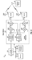
- FIG. 4 shows a block diagram of an equalizer at the wireless device.
- FIGS. 5A and 5B show a sub-sampler and sub-sampling, respectively.
- FIG. 6 shows a computation unit for selective equalization.
- FIG. 7 shows a process for performing selective equalization.
- FIGS. 8A and 8B show computation units for separate equalization with equal and weighted combining, respectively.
- FIG. 9 shows a process for performing separate equalization with combining.
- FIG. 10 shows a computation unit for joint equalization.
- FIG. 11 shows a process for performing joint equalization.
- FIG. 12 shows a process for performing equalization with sub-sampling.
- FIG. 13 shows a process for performing equalization with coefficients derived in the frequency domain
- FIG. 14 shows a base station with multiple transmit antennas.
- FIG. 15 shows a wireless device with multiple receive antennas.
- FIG. 16 shows a base station using space-time transmit diversity (STTD).
- STTD space-time transmit diversity
- FIG. 1 shows an exemplary transmission in a wireless communication system.
- FIG. 1 shows only one base station 110 and one wireless device 120 .
- a base station is generally a fixed station that communicates with the wireless devices and may also be called a Node B, an access point, or some other terminology.
- a wireless device may be fixed or mobile and may also be called a user equipment (UE), a mobile station, a user terminal, a subscriber unit, or some other terminology.
- UE user equipment
- a wireless device may be a cellular phone, a personal digital assistant (PDA), a wireless modem card, or some other device or apparatus.
- PDA personal digital assistant
- Base station 110 transmits a radio frequency (RF) signal to wireless device 120 .
- This RF signal may reach wireless device 120 via one or more signal paths, which may include a direct path and/or reflected paths. The reflected paths are created by reflections of radio waves due to obstructions (e.g., buildings, trees, vehicles, and other structures) in the wireless environment.
- Wireless device 120 may receive multiple instances or copies of the transmitted RF signal. Each received signal instance is obtained via a different signal path and has a particular complex gain and a particular time delay determined by that signal path.
- the received RF signal at wireless device 120 is a superposition of all received signal instances at the wireless device.
- Wireless device 120 may also receive interfering transmissions from other transmitting stations. The interfering transmissions are shown by dashed lines in FIG. 1 .
- the equalization techniques described herein may be used for various communication systems such as CDMA, TDMA, FDMA, orthogonal frequency division multiple access (OFDMA), and single-carrier FDMA (SC-FDMA) systems.
- a CDMA system may implement one or more radio access technologies (RATs) such as cdma2000, Wideband-CDMA (W-CDMA), and so on.
- cdma2000 covers IS-2000, IS-856, and IS-95 standards.
- a TDMA system may implement a RAT such as Global System for Mobile Communications (GSM). These various RATs and standards are known in the art.
- W-CDMA and GSM are described in documents from a consortium named “3rd Generation Partnership Project” (3GPP).
- cdma2000 is described in documents from a consortium named “3rd Generation Partnership Project 2”(3GPP2). 3GPP and 3GPP2 documents are publicly available.
- An OFDMA system transmits modulation symbols in the frequency domain on orthogonal frequency subcarriers using OFDM.
- An SC-FDMA system transmits modulation symbols in the time domain on orthogonal frequency subcarriers.
- the equalization techniques described herein may also be used for a wireless device as well as a base station. For clarity, these techniques are described below for a wireless device in a CDMA system, which may be a W-CDMA system or a cdma2000 system. Certain portions of the description are for a W-CDMA system.
- FIG. 2 shows a block diagram of base station 110 and wireless device 120 .
- a transmit (TX) data processor 210 receives traffic data for the wireless devices being served, processes (e.g., encodes, interleaves, and symbol maps) the traffic data to generate data symbols, and provides the data symbols to a CDMA modulator 220 .
- a data symbol is a modulation symbol for data
- a pilot symbol is a modulation symbol for pilot
- a modulation symbol is a complex value for a point in a signal constellation (e.g., for M-PSK, M-QAM, and so on)
- a symbol is generally a complex value
- pilot is data that is known a priori by both the base station and the wireless device.
- CDMA modulator 220 processes the data symbols and pilot symbols as described below and provides output chips to a transmitter (TMTR) 230 .
- Transmitter 230 processes (e.g., converts to analog, amplifies, filters, and frequency upconverts) the output chips and generates an RF signal, which is transmitted from an antenna 232 .
- an antenna 252 receives the transmitted RF signal via direct and/or reflected paths and provides a received RF signal to a receiver (RCVR) 254 .
- Receiver 254 processes (e.g., filters, amplifies, frequency downconverts, and digitizes) the received RF signal to obtain received samples.
- Receiver 254 may also perform pre-processing on the received samples and provides input samples to an equalizer 260 .
- the pre-processing may include, e.g., automatic gain control (AGC), frequency correction, digital filtering, sample rate conversion, and so on.
- Equalizer 260 performs equalization on the input samples as described below and provides output samples.
- a CDMA demodulator (Demod) 270 processes the output samples in a manner complementary to the processing by CDMA modulator 220 and provides symbol estimates, which are estimates of the data symbols sent by base station 110 to wireless device 120 .
- a receive (RX) data processor 280 processes (e.g., symbol demaps, deinterleaves, and decodes) the symbol estimates and provides decoded data.
- the processing by CDMA demodulator 270 and RX data processor 280 is complementary to the processing by CDMA modulator 220 and TX data processor 210 , respectively, at base station 110 .
- Controllers/processors 240 and 290 direct operation of various processing units at base station 110 and wireless device 120 , respectively.
- Memories 242 and 292 store data and program codes for base station 110 and wireless device 120 , respectively.
- multiple orthogonal channels may be obtained with different orthogonal codes.
- multiple orthogonal physical channels are obtained with different orthogonal variable spreading factor (OVSF) codes in W-CDMA
- OVSF orthogonal variable spreading factor
- multiple orthogonal traffic channels are obtained with different Walsh codes in cdma2000.
- the orthogonal channels may be used to send different types of data (e.g., traffic data, control data, broadcast data, pilot, and so on) and/or traffic data for different wireless devices.
- FIG. 3 shows a block diagram of CDMA modulator 220 at base station 110 .
- CDMA modulator 220 includes a physical channel processor 310 for each physical channel used for traffic data and a pilot channel processor 320 for pilot.
- processor 310 for physical channel i used for wireless device 120 a spreader 312 spreads data symbols with an OVSF code o i (n) for physical channel i and provides data chips.
- Spreader 312 repeats each data symbol multiple times to generate N replicated symbols, where N is the length of OVSF code o i (n).
- Spreader 312 then multiplies the N replicated symbols with the N chips of OVSF code o i (n) to generate N data chips for the data symbol.
- a scrambler 314 multiplies the data chips with a scrambling sequence s p (n) for base station 110 .
- a multiplier 316 scales the output of scrambler 314 and provides output chips x(n) for physical channel i.
- a spreader 322 spreads pilot symbols with an OVSF code o p (n) for pilot, which is a sequence of all zeros, and provides pilot chips.
- a scrambler 324 multiplies the pilot chips with the scrambling sequence s p (n).
- a multiplier 326 scales the output of scrambler 324 and provides output chips p(n) for the pilot channel.
- a summer 330 sums the output chips for all physical channels and provides output chips z(n) for base station 110 .
- the chip rate is 3.84 mega-chips/second (Mcps) for W-CDMA and is 1.2288 Mcps for cdma2000.
- time-domain input samples from receiver 254 may be expressed as:
- a frequency-domain representation may be obtained by taking a discrete Fourier transform (DFT) or a fast Fourier transform (FFT) of a time-domain representation.
- a time-domain representation may be obtained by taking an inverse discrete Fourier transform (IDFT) or an inverse fast Fourier transform (IFFT) of a frequency-domain representation.
- IDFT inverse discrete Fourier transform
- IFFT inverse fast Fourier transform
- LMMSE linear minimum mean square error
- the LMMSE filtering in (3) may also be performed in the time domain by convolving the input samples with a finite impulse response (FIR) filter having a frequency response of C( ⁇ ), as follows:
- c(n) and ⁇ circumflex over (x) ⁇ (n) are time-domain representations of C( ⁇ ) and ⁇ circumflex over (X) ⁇ ( ⁇ ), respectively, and 2 L is the length of the FIR filter.
- the received signal may be sampled at multiple (M) times the chip rate to obtain an over-sampled signal with M input samples for M sampling time instants in each chip period, where in general M>1.
- the M sampling time instants may be evenly spaced apart across a chip period and separated by T c /M, where T c is one chip period.
- the over-sampled signal may be demultiplexed or sub-sampled to obtain M sub-sampled signals.
- Each sub-sampled signal contains input samples for one sampling time instant.
- the input samples for each sub-sampled signal are separated by one chip period.
- the quality of the sampled data is affected by the sampling time instant.
- the M sub-sampled signals may have different qualities and may be processed as described below to obtain an improved estimate of the transmitted signal.
- the over-sampled signal is not stationary, but the M sub-sampled signals are stationary, which means that the statistics of the sub-sampled signals do not change if the origin or start of these signals is shifted. This stationary property of the sub-sampled signals may be exploited to derive equalizer coefficients that can provide a good estimate of the transmitted signal.
- the M sub-sampled signals may be viewed as M diversity branches, or simply, branches. Each branch corresponds to a different sampling time instant.
- the equalization techniques described herein may be used with any amount of oversampling. For clarity, the equalization techniques are specifically described below for the case in which the received signal is over-sampled at twice the chip rate (or Chip ⁇ 2) to obtain input samples at Chip ⁇ 2. Equalization may be performed on the Chip ⁇ 2 input samples as described below.
- FIG. 4 shows a block diagram of an embodiment of equalizer 260 in FIG. 2 .
- the Chip ⁇ 2 input samples y(n) are provided to a channel estimator 410 and a sub-sampler 414 .
- Channel estimator 410 derives a channel impulse response estimate h(n) for the wireless channel between base station 110 and wireless device 120 .
- the channel impulse response estimate h(n) is over-sampled and contains 2 L channel taps that are separated by half chip period.
- a sub-sampler 412 demultiplexes the over-sampled channel taps h(n) into on-time channel taps h 1 (n) and late channel taps h 2 (n) for two sampling time instants.
- sub-sampler 414 demultiplexes the Chip ⁇ 2 input samples y(n) into on-time samples y 1 (n) and late samples y 2 (n) for the two sampling time instants.
- a covariance estimator 416 determines the covariance of the on-time and late samples as described below and provides covariance values.
- a computation unit 420 receives the on-time and late channel taps from sub-sampler 412 and the covariance values from estimator 416 . Computation unit 420 derives equalizer coefficients c 1 (n) and c 2 (n) for the two sampling time instants based on the channel taps and the covariance values, as described below.
- a FIR filter 430 filters the on-time and late samples y 1 (n) and y 2 (n) with the equalizer coefficients c 1 (n) and c 2 (n) and provides output samples ⁇ circumflex over (x) ⁇ (n) at chip rate (or Chip ⁇ 1).
- FIG. 5A shows a block diagram of an embodiment of sub-sampler 414 in FIG. 4 .
- the Chip ⁇ 2 input samples y(n) are provided to a delay unit 510 and a down-sampler 514 .
- Delay unit 510 provides a delay of half chip period.
- a down-sampler 512 provides every other sample from delay unit 510 as the on-time samples y 1 (n).
- Down-sampler 514 provides every other input samples as the late samples y 2 (n).
- the on-time samples y 1 (n) and the late samples y 2 (n) are for two sampling time instants or branches and comprise all of the Chip ⁇ 2 input samples y(n).
- FIG. 5B shows the on-time samples y 1 (n) and late samples y 2 (n) from sub-sampler 414 .
- the on-time samples y 1 (n) are offset by half chip period from the late samples y 2 (n).
- channel estimator 410 may derive a channel impulse response estimate based on the pilot transmitted by base station 110 .
- the channel impulse response estimate ⁇ (n) may be derived as follows:
- K is an accumulation length, which is an integer multiple of the length of the orthogonal code used for the pilot.
- the OVSF code for the pilot in W-CDMA has a length of 256 chips
- the Walsh code for the pilot in cdma2000 has a length of 128 chips.
- the channel tap at index n is obtained by descrambling the input samples with the scrambling sequence s p (n), despreading the descrambled samples with the pilot OVSF code o p (n), and accumulating over K chip periods.
- Sub-sampler 412 demultiplexes the 2 L channel taps of the channel impulse response estimate h(n) into L on-time channel taps h 1 (n) and L late channel taps h 2 (n).
- Sub-sampler 412 may be implemented in the same manner as sub-sampler 414 in FIG. 5A .
- the on-time channel taps h 1 (n) represent the channel impulse response estimate for the on-time samples y 1 (n).
- the late channel taps h 2 (n) represent the channel impulse response estimate for the late samples y 2 (n).
- a Chip ⁇ 2 system may be considered as having a single-input multiple-output (SIMO) channel.
- equalization may be performed for a given branch based on an LMMSE filter derived for that branch.
- the LMMSE filter for each branch m may be expressed as:
- Covariance estimator 416 in FIG. 4 may estimate the covariance of y 1 (n) and y 2 (n), as follows:
- ij ( ⁇ ) denotes the covariance between y i (n) and y j (n ⁇ ), which is a time-shifted version of y j (n).
- covariance covers both auto-correlation of a given sub-sampled signal y m (n) and cross-correlation between two sub-sampled signals y 1 (n) and y 2 (n).
- the covariance may also be estimated in other manners known in the art.
- FIG. 6 shows a block diagram of an equalizer coefficient computation unit 420 a for the selective equalization scheme.
- Computation unit 420 a is an embodiment of computation unit 420 in FIG. 4 .
- an energy computation unit 610 receives the on-time and late channel taps h 1 (n) and h 2 (n) and computes the energy E m of the channel taps for each branch m, as follows:
- Unit 610 determines the best branch r as the branch with the largest energy, as follows:
- r arg ⁇ ( max m ⁇ ⁇ E m ⁇ ) , Eq ⁇ ⁇ ( 11 ) where r ⁇ 1, 2 ⁇ .
- a selector 612 receives the on-time channel taps h 1 (n) and the late channel taps h 2 (n) and provides the channel taps h r (n) for the best branch r.
- a selector 616 receives the covariance values 11 ( ⁇ ) for the on-time samples and the covariance values 22 ( ⁇ ) for the late samples and provides the covariance values rr ( ⁇ ) for the best branch r.
- An FFT unit 618 performs an L-point FFT on the covariance values, which may be arranged as ⁇ 11 (0), . . . , rr (L/2 ⁇ 1), 0, rr * (L/2 ⁇ 1), . . . , rr * (1) ⁇ , where a zero is inserted to obtain L values for the FFT.
- a computation unit 620 then computes frequency-domain equalizer coefficients C r ( ⁇ )) for the best branch r, as follows:
- Unit 620 may condition R rr ( ⁇ ) prior to computing for C r ( ⁇ ). For example, unit 620 may determine the largest value of R rr ( ⁇ ) as
- unit 620 may constrain R rr ( ⁇ ) to be greater than or equal to a predetermined value, e.g., R rr ( ⁇ ) ⁇ 0.01 ⁇ M.
- An IFFT unit 622 performs an L-point IFFT on the L frequency-domain equalizer coefficients C r ( ⁇ ) and provides L time-domain equalizer coefficients c r (n) for the best branch r.
- FIR filter 430 may filter the on-time and late samples based on the equalizer coefficients, as follows:
- FIG. 7 shows a process 700 for performing equalization selectively for the best branch.
- a channel impulse response estimate h(n) for a wireless channel is derived, e.g., based on a received pilot (block 712 ).
- Multiple (M) channel impulse response estimates h 1 (n) through h M (n) for M sampling time instants are derived based on (e.g., by sub-sampling) the channel impulse response estimate h(n) (block 714 ).
- M may be equal to two, as described above, or may be greater than two.
- the M sampling time instants correspond to M different branches.
- One sampling time instant is selected from among the M sampling time instants and denoted as sampling time instant r (block 716 ).
- the selection of the best sampling time instant may be achieved by computing the energy of the channel taps for each sampling time instant and comparing the energies for the M sampling time instants to determine the sampling time instant with the largest energy.
- a channel frequency response estimate H r ( ⁇ ) for the selected sampling time instant is derived based on (e.g., by performing an FFT on) the channel impulse response estimate h r (n) for the selected sampling time instant (block 718 ).
- Time-domain covariance values rr ( ⁇ ) for input samples y r (n) for the selected sampling time instant are determined, e.g., as shown in equation (9) (block 720 ).
- Frequency-domain covariance values R rr ( ⁇ ) are determined based on (e.g., by performing an FFT on) the time-domain covariance values rr ( ⁇ ) (block 722 ).
- Frequency-domain equalizer coefficients C r ( ⁇ ) for the selected sampling time instant are then derived based on the channel frequency response estimate H r ( ⁇ ) and the frequency-domain covariance values R rr ( ⁇ ) (block 724 ).
- the equalizer coefficients may be computed based on the LMMSE technique, as shown in equation (12), or based on some other equalization technique.
- Time-domain equalizer coefficients c r (n) for the selected sampling time instant are determined based on (e.g., by performing an IFFT on) the frequency-domain equalizer coefficients C r ( ⁇ ) (block 726 ).
- the input samples y r (n) for the selected sampling time instant are filtered with the time-domain equalizer coefficients c r (n) (block 728 ).
- FIG. 8A shows a block diagram of an equalizer coefficient computation unit 420 b for the separate equalization with combining scheme.
- Computation unit 420 b performs equal combining of the two branches and is another embodiment of computation unit 420 in FIG. 4 .
- an FFT unit 810 transforms the on-time channel taps h 1 (n) with an L-point FFT and provides L channel gains H 1 ( ⁇ ) for branch 1 .
- An FFT unit 812 transforms the late channel taps h 2 (n) with an L-point FFT and provides L channel gains H 2 ( ⁇ ) for branch 2 .
- An FFT unit 814 performs an L-point FFT on time-domain covariance values 11 ( ⁇ ) for branch 1 , which may be arranged as ⁇ 11 (0), . . . , 11 (L/2 ⁇ 1), 0, 11 * (L/2 ⁇ 1), . . .
- a computation unit 820 computes frequency-domain equalizer coefficients C 1 ( ⁇ ) for branch 1 based on the channel gains H 1 ( ⁇ ) and the covariance values R 11 ( ⁇ ) for branch 1 , e.g., as shown in equation (12).
- a computation unit 822 computes frequency-domain equalizer coefficients C 2 ( ⁇ ) for branch 2 based on the channel gains H 2 ( ⁇ ) and the covariance values R 22 ( ⁇ ) for branch 2 .
- An IFFT unit 830 performs an L-point IFFT on the L frequency-domain equalizer coefficients C 1 ( ⁇ ) and provides L time-domain equalizer coefficients c 1 (n) for branch 1 .
- An IFFT unit 832 performs an L-point IFFT on the L frequency-domain equalizer coefficients C 2 ( ⁇ ) and provides L time-domain equalizer coefficients c 2 (n) for branch 2 .
- the equalizer coefficients c 1 (n) and c 2 (n) are used to filter the on-time samples y 1 (n) and the late samples c 2 (n), as shown in equation (14).
- FIG. 8B shows a block diagram of an equalizer coefficient computation unit 420 c for the separate equalization with combining scheme.
- Computation unit 420 c performs weighted combining of the two branches and is yet another embodiment of computation unit 420 in FIG. 4 .
- Computation unit 420 c includes FFT units 810 , 812 , 814 and 816 , coefficient computation units 820 and 822 , and IFFT units 830 and 832 that operate as described above for FIG. 8A .
- Computation unit 420 c further includes weight computation units 824 and 826 and multipliers 834 and 836 .
- Unit 824 receives the on-time channel taps h 1 (n) and computes the weight for branch 1 .
- Unit 826 receives the late channel taps h 2 (n) and computes the weight for branch 2 .
- the weight q m for each branch m may be computed as follows:
- the coefficients for each branch are scaled by the weight for that branch.
- the scaling is performed on the time-domain equalizer coefficients.
- Multiplier 834 is located after IFFT unit 830 , scales each time-domain equalizer coefficient c 1 ′(n) from FFT unit 830 with the weight q 1 for branch 1 , and provides L output equalizer coefficients c 1 (n) for branch 1 .
- multiplier 836 is located after IFFT unit 832 , scales each time-domain coefficient c 2 ′(n) from FFT unit 832 with the weight q 2 for branch 2 , and provides L output equalizer coefficients c 2 (n) for branch 2 .
- the scaling is performed on the frequency-domain equalizer coefficients C m ( ⁇ ).
- multipliers 834 and 836 would be located after computation units 820 and 822 , respectively.
- FIG. 9 shows a process 900 for performing equalization separately for each branch and combining the results.
- a channel impulse response estimate h 1 (n) for a wireless channel is derived, e.g., based on a received pilot (block 912 ).
- a first channel impulse response estimate h 1 (n) for a first sampling time instant and a second channel impulse response estimate h 2 (n) for a second sampling time instant are derived based on (e.g., by sub-sampling) the channel impulse response estimate h(n) (block 914 ).
- a first channel frequency response estimate H 1 ( ⁇ ) for the first sampling time instant is derived based on (e.g., by performing an FFT on) the first channel impulse response estimate h 1 (n) (block 916 ).
- a second channel frequency response estimate H 2 ( ⁇ ) for the second sampling time instant is derived based on the second channel impulse response estimate h 2 (n) (also block 916 ).
- Time-domain covariance values 11 ( ⁇ ) for input samples y 1 (n) for the first sampling time instant and time-domain covariance values 22 ( ⁇ ) for input samples y 2 (n) for the second sampling time instant are determined (block 918 ).
- Frequency-domain covariance values R 11 ( ⁇ ) for the first sampling time instant are determined based on (e.g., by performing an FFT on) the time-domain covariance values 11 ( ⁇ ) (block 920 ).
- Frequency-domain covariance values R 22 ( ⁇ ) for the second sampling time instant are determined based on the time-domain covariance values 22 ( ⁇ ) (also block 920 ).
- Frequency-domain equalizer coefficients C 1 ( ⁇ ) for the first sampling time instant are derived based on the channel frequency response estimate H 1 ( ⁇ ) and the frequency-domain covariance values R 11 ( ⁇ ) (block 922 ).
- Frequency-domain equalizer coefficients C 2 ( ⁇ ) for the second sampling time instant are derived based on the channel frequency response estimate H 2 ( ⁇ ) and the frequency-domain covariance values R 22 ( ⁇ ) (also block 922 ).
- the equalizer coefficients may be computed based on the LMMSE technique, as shown in equation (12), or based on some other equalization technique.
- Time-domain equalizer coefficients c 1 ′(n) for the first sampling time instant are determined based on (e.g., by performing an IFFT on) the frequency-domain equalizer coefficients C 1 ( ⁇ ) (block 924 ).
- Time-domain equalizer coefficients c 2 ′(n) for the second sampling time instant are determined based on the frequency-domain equalizer coefficients C 2 ( ⁇ ) (also block 924 ).
- the time-domain equalizer coefficients c 1 ′(n) for the first sampling time instant are scaled by a first weight q 1 to obtain output equalizer coefficient c 1 (n) (block 926 ).
- the time-domain equalizer coefficients c 2 ′(n) for the second sampling time instant are scaled by a second weight q 2 to obtain output equalizer coefficient c 2 (n) (also block 926 ).
- the first and second weights may be equal or may be derived based on the energies of h 1 (n) and h 2 (n), respectively.
- the input samples are filtered with the output equalizer coefficients c 1 (n) and c 2 (n) (block 928 ).
- FIG. 10 shows a block diagram of an equalizer coefficient computation unit 420 d for the joint equalization scheme.
- Computation unit 420 d is yet another embodiment of computation unit 420 in FIG. 4 .
- an FFT unit 1010 transforms the on-time channel taps h 1 (n) and provides L channel gains H 1 ( ⁇ ) for branch 1 .
- An FFT unit 1012 transforms the late channel taps h 2 (n) and provides L channel gains H 2 ( ⁇ ) for branch 2 .
- a computation unit 1020 jointly computes the frequency-domain equalizer coefficients C 1 ( ⁇ ) and C 2 ( ⁇ ) for branches 1 and 2 , as described below.
- An IFFT unit 1030 transforms the frequency-domain equalizer coefficients C 1 ( ⁇ ) and provides time-domain equalizer coefficients c 1 (n) for branch 1 .
- An IFFT unit 1032 transforms the frequency-domain equalizer coefficients C 2 ( ⁇ ) and provides time-domain equalizer coefficients c 2 (n) for branch 2 .
- the on-time and late samples y 1 (n) and y 2 (n) are equalized with two sets of equalizer coefficients c 1 (n) and c 2 (n) that are derived jointly such that the output samples ⁇ circumflex over (x) ⁇ (n) in equation (14) provide the best linear approximation of x(n) in the mean square error sense.
- the LMMSE solutions for the two sets of equalizer coefficients may be expressed in the frequency domain, as follows:
- Each 2 ⁇ 2 matrix may be inverted and used to derive the equalizer coefficients C 1 ( ⁇ ) and C 2 ( ⁇ ) for one frequency bin ⁇ .
- a given 2 ⁇ 2 matrix may be poorly conditioned, e.g., close to singular because of estimation errors. The inversion of a poorly conditioned matrix may produce a large entry that may excessively enhance noise.
- Several techniques may be used to deal with poorly conditioned matrices.
- the joint processing of the two branches is performed with “diagonal” conditioning.
- This scaling for a single tap of mm ( ⁇ ) introduces a small spectral component in each frequency bin of R mm ( ⁇ ), which makes the frequency domain matrices “more invertible”.
- FFTs are then performed on the conditioned 11 ( ⁇ ) and 22 ( ⁇ ) .
- Computation unit 1020 may then compute the frequency-domain equalizer coefficients C 1 ( ⁇ ) and C 2 ( ⁇ ) for branches 1 and 2 , respectively, as follows:
- the joint processing of the two branches is performed with “pseudo-inverse” conditioning.
- the equalizer coefficients C 1 ( ⁇ ) and C 2 ( ⁇ ) for each frequency bin ⁇ may be computed in one of several manners depending on whether or not the 2 ⁇ 2 matrix for that frequency bin is poorly conditioned.
- Equation (18) checks if a “condition number” of the 2 ⁇ 2 matrix for frequency bin ⁇ is below a certain value. This condition may be used to determine whether or not the 2 ⁇ 2 matrix is poorly conditioned.
- the frequency-domain equalizer coefficients C 1 ( ⁇ ) and C 2 ( ⁇ ) for that frequency bin may be computed as shown in equation (17).
- the frequency-domain equalizer coefficients C 1 ( ⁇ ) and C 2 ( ⁇ ) for that frequency bin may be computed as follows. The following quantities are computed for frequency bin ⁇ :
- the frequency-domain equalizer coefficients C 1 ( ⁇ ) and C 2 ( ⁇ ) for frequency bin ⁇ may then be computed as follows:
- Equation (21) may be approximated as follows:
- Equation (21) may also be approximated as follows:
- FIG. 11 shows a process 1100 for performing equalization jointly for multiple branches.
- a channel impulse response estimate h(n) for a wireless channel is derived, e.g., based on a received pilot (block 1112 .
- First and second channel impulse response estimates h 1 (n) and h 2 (n) for first and second sampling time instants, respectively, are derived based on (e.g., by sub-sampling) the channel impulse response estimate h(n) (block 1114 ).
- First and second channel frequency response estimates H 1 ( ⁇ ) and H 2 ( ⁇ ) for the first and second sampling time instants are derived based on the first and second channel impulse response estimates h 1 (n) and h 2 (n), respectively (block 1116 ).
- Time-domain covariance values 11 ( ⁇ ), 22 ( ⁇ ) and 12 ( ⁇ ) for input samples y 1 (n) and y 2 (n) for the first and second sampling time instants are determined (block 1118 ).
- Frequency-domain covariance values R 11 ( ⁇ ), R 22 ( ⁇ ) and R 12 ( ⁇ ) are determined based on the time-domain covariance values 11 ( ⁇ ), 22 ( ⁇ ) and 12 ( ⁇ ), respectively (block 1120 ).
- Frequency-domain equalizer coefficients C 1 ( ⁇ ) and C 2 ( ⁇ ) for the first and second sampling time instants are derived jointly based on the first and second channel frequency response estimates H 1 ( ⁇ ) and H 2 ( ⁇ ) and the frequency-domain covariance values R 11 ( ⁇ ), R 22 ( ⁇ ) and R 12 ( ⁇ ) (block 1122 ).
- the equalizer coefficients may be computed based on the LMMSE technique, as shown in equations (16) through (23), or based on some other equalization technique.
- Time-domain equalizer coefficients c 1 (n) and c 2 (n) for the first and second sampling time instants are determined based on the frequency-domain equalizer coefficients C 1 ( ⁇ ) and C 2 ( ⁇ ), respectively (block 1124 ).
- the input samples are then filtered with the time-domain equalizer coefficients c 1 (n) and c 2 (n) (block 1126 ).
- FIG. 12 shows a process 1200 for performing equalization on an over-sampled input signal with sub-sampling.
- the over-sampled input signal is sub-sampled or demultiplexed to obtain multiple sub-sampled signals (block 1212 ).
- An over-sampled channel estimate is derived, e.g., based on a received pilot (block 1214 ).
- the over-sampled channel estimate may be a channel impulse response estimate that is over-sampled in time, a channel frequency response estimate that is over-sampled in frequency, and so on.
- the over-sampled channel estimate is sub-sampled to obtain multiple sub-sampled channel estimates (block 1216 ).
- Equalization is performed on the multiple sub-sampled signals with the multiple sub-sampled channel estimates to obtain at least one output signal.
- at least one set of equalizer coefficients may be derived based on at least one sub-sampled channel estimate using any of the equalization schemes described above (block 1218 ).
- the equalizer coefficients may be derived in the time domain or frequency domain.
- At least one sub-sampled signal is then filtered with the at least one set of equalizer coefficients to obtain the at least one output signal (block 1220 ).
- FIG. 13 shows a process 1300 for performing equalization on an over-sampled input signal with equalizer coefficients derived in the frequency domain.
- a channel impulse response estimate is derived, e.g., based on a received pilot (block 1312 ).
- a channel frequency response estimate is derived based on (e.g., by performing an FFT on) the channel impulse response estimate (block 1314 ).
- time-domain covariance values for the input samples may be determined (block 1316 ) and transformed to obtain frequency-domain covariance values (block 1318 ).
- Frequency-domain equalizer coefficients are derived for multiple frequency bins based on the channel frequency response estimate and the frequency-domain covariance values (block 1320 ).
- Time-domain equalizer coefficients are derived based on (e.g., by performing an IFFT on) the frequency-domain equalizer coefficients (block 1322 ).
- the input samples are then filtered with the time-domain equalizer coefficients to obtain output samples (block 1324 )
- the equalization techniques have been described mostly for the case in which the input samples y(n) are at Chip ⁇ 2 and there are two branches corresponding to two sampling time instants.
- the equalization techniques may be used for input samples that are over-sampled at multiple (M) times the chip rate, where M ⁇ 2.
- M branches may be formed for M sampling time instants.
- M sequences of input samples y 1 (n) through y M (n) for M sampling time instants may be obtained by sub-sampling or demultiplexing the over-sampled input samples y(n).
- M channel impulse response estimates h 1 (n) through h M (n) for M sampling time instants may be obtained by sub-sampling or demultiplexing an over-sampled channel impulse response estimate h(n) for the wireless channel.
- Covariance values ij ( ⁇ ), for i,j ⁇ 1, . . . , M ⁇ , may be derived based on the input samples y(n), e.g., as shown in equation (9).
- the best branch may be selected, e.g., based on the energies of the channel impulse response estimates for the M branches.
- Equalizer coefficients for the best branch may be derived based on the channel impulse response estimate and the covariance values for that branch.
- the input samples for the best branch are filtered with the equalizer coefficients for that branch.
- a set of equalizer coefficients may be derived for each branch based on the channel impulse response estimate and the covariance values for that branch.
- the M sets of equalizer coefficients for the M branches may be scaled with equal weights for all M branches or different weights determined based on the energies for the M branches.
- the input samples are filtered with the M sets of equalizer coefficients for the M branches.
- M sets of equalizer coefficients for the M branches may be derived jointly based on the channel impulse response estimates and the covariance values for all M branches.
- the input samples are filtered with the M sets of equalizer coefficients for the M branches.
- the channel impulse response estimate h(n), the covariance values ij ( ⁇ ), and the equalizer coefficients c m (n) may be updated at a sufficient rate to achieve good performance.
- h(n), ij ( ⁇ ) and c m (n) may be updated whenever a new pilot symbol is received, whenever a predetermined number of pilot symbols is received, in each slot, in each frame, and so on.
- a pilot symbol is sent in 256 chips, each slot spans 2560 chips or 10 pilot symbols, and each frame includes 15 slots.
- cdma2000 a pilot symbol is sent in 128 chips, each slot spans 768 chips or 6 pilot symbols, and each frame includes 16 slots.
- equalization techniques have been described for a transmitter with a single antenna and a receiver with a single antenna. These techniques may also be used for a transmitter with multiple antennas and for a receiver with multiple antennas, as described below.
- FIG. 14 shows a block diagram of a base station 112 with two transmit antennas 1432 a and 1432 b .
- a TX data processor 1410 processes traffic data and generates data symbols.
- a CDMA modulator 1420 processes data and pilot symbols and generates output chips z 1 (n) and z 2 (n) for transmit antennas 1432 a and 1432 b , respectively.
- a physical channel processor 1422 processes data symbols for physical channel i and generates output chips x(n) for this physical channel.
- a pilot channel processor 1424 generates output chips p 1 (n) and p 2 (n) for the pilot for transmit antennas 1432 a and 1432 b , respectively.
- Processors 1422 and 1424 may be implemented with processors 310 and 320 , respectively, in FIG. 3 .
- a multiplier 1426 a scales the output chips x(n) with a weight v 1 for transmit antenna 1432 a and generates scaled output chips x 1 (n).
- a multiplier 1426 b scales the output chips x(n) with a weight v 2 for transmit antenna 1432 b and generates scaled output chips x 2 (n).
- a summer 1428 a sums the output chips for all physical channels for transmit antenna 1432 a and provides output chips z 1 (n).
- a summer 1428 b sums the output chips for all physical channels for transmit antenna 1432 b and provides output chips z 2 (n).
- a transmitter 1430 a processes the output chips z 1 (n) and generates a first RF signal, which is transmitted from antenna 1432 a .
- a transmitter 1430 b processes the output chips z 2 (n) and generates a second RF signal, which is transmitted from antenna 1432 b .
- a controller/processor 1440 directs operation at base station 112 .
- a memory 1442 stores data and program codes for base station 112 .
- the weights v 1 and v 2 may be selected by wireless device 120 and sent back to base station 112 .
- the weights v 1 and v 2 may be selected to maximize the received signal at wireless device 120 .
- the weights v 1 and v 2 may be derived by the wireless device and/or the base station in various manners.
- the input samples y(n) may be expressed as:
- h 1 (n) is an impulse response from antenna 1432 a to wireless device 120 .
- a channel impulse response estimate h 1 (n) for transmit antenna 1432 a may be derived based on the pilot p 1 (n) transmitted from this antenna.
- a channel impulse response estimate h 2 (n) for transmit antenna 1432 b may be derived based on the pilot p 2 (n) transmitted from this antenna.
- An effective channel impulse response estimate h eff (n) may then be derived based on h 1 (n) and h 2 (n) and the known weights v 1 and v 2 .
- h eff (n) may also be derived in other manners.
- h eff (n) may be sub-sampled to obtain effective channel impulse response estimates h eff,1 (n) through h eff,M (n) for M branches corresponding to M sampling time instants. Equalization may be performed for the best branch, separately for the M branches and combined, or jointly for all M branches, as described above.
- FIG. 15 shows a block diagram of a wireless device 122 with two receive antennas 1552 a and 1552 b .
- a receiver 1554 a processes a first received RF signal from antenna 1552 a and provides input samples y 1 (n) for this antenna.
- a receiver 1554 b processes a second received RF signal from antenna 1552 b and provides input samples y 2 (n) for this antenna.
- An equalizer 1560 performs equalization on the input samples y 1 (n) and y 2 (n) as described below and provides output samples ⁇ circumflex over (x) ⁇ (n).
- a CDMA demodulator 1570 processes the output samples and provides symbol estimates.
- An RX data processor 1580 processes the symbol estimates and provides decoded data.
- a controller/processor 1590 directs operation at wireless device 122 .
- a memory 1592 stores data and program codes for wireless device 122 .
- a channel impulse response estimate h 1 (n) for receive antenna 1552 a may be derived based on the pilot received via this antenna.
- a channel impulse response estimate h 2 (n) for receive antenna 1552 b may be derived based on the pilot received via this antenna.
- the input samples y ⁇ (n) for each receive antenna ⁇ may be sub-sampled to obtain input samples y 1 ⁇ (n) through y M ⁇ (n) for M branches for that antenna.
- equalization techniques described above may be applied to the input samples y 1 1 (n), y 2 1 (n), y 1 2 (n) and y 2 2 (n) for four branches formed by two sampling time instants and two receive antennas.
- the best branch having the largest energy among the four branches may be selected for equalization.
- equalization may be performed separately for four branches, for two best branches among the four branches, for the best branch for each receive antenna, and so on.
- the results for all selected branches may be combined to generate the output samples ⁇ circumflex over (x) ⁇ (n).
- equalization may be performed jointly for four branches, for two best branches among the four branches, for two best branches for the two receive antennas, and so on.
- the best branch is determined for each receive antenna, and equalization is performed for the two best branches for the two receive antennas.
- the energy of each of the four branches may be determined, e.g., as shown in equation (10).
- the branch with more energy is selected and denoted as r( ⁇ ).
- Input samples y r(1) 1 (n) and y r(2) 2 (n) and channel impulse response estimates h r(1) 1 (n) and h r(2) 2 (n) may then be processed based on any of the equalization schemes described above to obtain the output samples ⁇ circumflex over (x) ⁇ (n).
- FIG. 16 shows a block diagram of a base station 114 using space-time transmit diversity (STTD).
- a TX data processor 1610 processes traffic data and generates data symbols s(l).
- a CDMA modulator 1620 processes data and pilot symbols and generates output chips z 1 (n) and z 2 (n) for two transmit antennas 1632 a and 1632 b.
- Physical channel processors 1624 a and 1624 b process STTD encoded symbols s 1 (l) and s 2 (l), respectively, and provide output chips x 1 (n) and x 2 (n), respectively.
- a pilot channel processor 1626 generates output chips p 1 (n) and p 2 (n) for the pilot for transmit antennas 1632 a and 1632 b , respectively.
- Processors 1624 and 1626 may be implemented with processors 310 and 320 , respectively, in FIG. 3 .
- Summers 1628 a and 1628 b sum the output chips for all physical channels for transmit antennas 1632 a and 1632 b , respectively, and provide output chips z 1 (n) and z 2 (n), respectively.
- Transmitters 1630 a and 1630 b process the output chips z 1 (n) and z 2 (n), respectively, and generate two RF signals that are transmitted from antennas 1632 a and 1632b, respectively.
- a controller/processor 1640 directs operation at base station 114 .
- a memory 1642 stores data and program codes for base station 114 .
- a channel impulse response estimate h 1 (n) for transmit antenna 1632 a may be derived based on the pilot p 1 (n) received from this antenna.
- the desired signals x 1 (n) and x 2 (n) may be recovered in various manners.
- the desired signals x 1 (n) and x 2 (n) are recovered by performing equalization for the best sampling time instant.
- the sampling time instant r with the larger energy is selected.
- Equalizer coefficients c r 1 (n) may be computed for transmit antenna 1632 a and sampling time instant r based on h r 1 (n) and possibly covariance values.
- equalizer coefficients c r 2 (n) may be computed for transmit antenna 1632 b and sampling time instant r based on h r 2 (n) and possibly covariance values.
- Input samples y r (n) for sampling time instant r are then filtered with the equalizer coefficients c r 1 (n) to obtain output samples ⁇ circumflex over (x) ⁇ 1 (n), which are estimates of output chips x 1 (n).
- the input samples y r (n) are also filtered with the equalizer coefficients c r 2 (n) to obtain output samples ⁇ circumflex over (x) ⁇ 2 (n), which are estimates of output chips ⁇ circumflex over (x) ⁇ 2 (n).
- CDMA demodulation may then be performed on the output samples ⁇ circumflex over (x) ⁇ 1 (n) to obtain symbol estimates ⁇ 1 (l), which are estimates of the STTD encoded symbols s 1 (l) transmitted from antenna 1632 a .
- CDMA demodulation may also be performed on the output samples ⁇ circumflex over (x) ⁇ 2 (n) to obtain symbol estimates ⁇ 2 (l), which are estimates of the STTD encoded symbols s 2 (l) transmitted from antenna 1632 b .
- STTD decoding may then be performed on ⁇ 1 (l) and ⁇ 2 (l) to obtain symbol estimates ⁇ (l) , which are estimates of data symbols s(l) for wireless device 120 .
- x 1 (n) is recovered by treating x 2 (n) as noise
- x 2 (n) is recovered by treating x 1 (n) as noise
- the equalization to recover x b (n), for b ⁇ 1, 2 ⁇ may be performed using any of the equalization schemes described above.
- equalizer coefficients may be derived in the time domain or frequency domain.
- equalizer coefficients may be derived using various techniques such as LMMSE, least mean square (LMS), recursive least square (RLS), direct matrix inversion (DMI), zero-forcing, and other techniques.
- LMS, RLS, and DMI are described by Simon Haykin in a book entitled “Adaptive Filter Theory”, 3rd edition, Prentice Hall, 1996.
- equalization techniques described herein may be implemented by various means. For example, these techniques may be implemented in hardware, firmware, software, or a combination thereof.
- the processing units used to perform equalization may be implemented within one or more application specific integrated circuits (ASICs), digital signal processors (DSPs), digital signal processing devices (DSPDs), programmable logic devices (PLDs), field programmable gate arrays (FPGAs), processors, controllers, micro-controllers, microprocessors, electronic devices, other electronic units designed to perform the functions described herein, or a combination thereof.
- ASICs application specific integrated circuits
- DSPs digital signal processors
- DSPDs digital signal processing devices
- PLDs programmable logic devices
- FPGAs field programmable gate arrays
- processors controllers, micro-controllers, microprocessors, electronic devices, other electronic units designed to perform the functions described herein, or a combination thereof.
- the equalization techniques may be implemented with modules (e.g., procedures, functions, and so on) that perform the functions described herein.
- the firmware and/or software codes may be stored in a memory (e.g., memory 292 in FIG. 2 ) and executed by a processor (e.g., processor 290 ).
- the memory may be implemented within the processor or external to the processor.
Abstract
Description
where x(n) is the signal component of interest for
-
- h(n) is an impulse response of the wireless channel between
base station 110 andwireless device 120, - w(n) is the total noise and interference observed by the desired signal x(n),
- y(n) is the input samples at
wireless device 120, and - {circle around (x)} denotes a convolution.
In equation (1), w(n) includes signal components for the other physical channels frombase station 110, noise from various sources, and interference from other transmitting stations. For simplicity, w(n) is assumed to be additive white Gaussian noise (AWGN) with zero mean and a variance of σ2.
- h(n) is an impulse response of the wireless channel between
Y(ω)=H(ω)·X(ω)+W(ω), Eq (2)
where Y(ω), H(ω), X(ω) and W(ω) are frequency-domain representations of y(n), h(n), x(n) and w(n), respectively. A frequency-domain representation may be obtained by taking a discrete Fourier transform (DFT) or a fast Fourier transform (FFT) of a time-domain representation. A time-domain representation may be obtained by taking an inverse discrete Fourier transform (IDFT) or an inverse fast Fourier transform (IFFT) of a frequency-domain representation. For simplicity, the desired signal X(ω) is assumed to be white with unit power. The whiteness assumption is reasonable because of the scrambling with the pseudo-random scrambling sequence sp(n) at
where C(ω) is an LMMSE filter response, {circumflex over (X)}(ω) is an estimate of X(ω), and “*” denotes a complex conjugate. As shown in equation (3), when σ2≈0 for high geometry, the LMMSE filter response becomes C(ω)≈1/H(ω), and the LMMSE filter inverts the channel. This results in elimination of multipaths. When σ2 is large for low geometry, the LMMSE filter response becomes C(ω)=H*(ω)/σ2, and the LMMSE filter performs matched filtering and is equivalent to a rake receiver.
where c(n) and {circumflex over (x)}(n) are time-domain representations of C(ω) and {circumflex over (X)}(ω), respectively, and 2 L is the length of the FIR filter.
where K is an accumulation length, which is an integer multiple of the length of the orthogonal code used for the pilot. The OVSF code for the pilot in W-CDMA has a length of 256 chips, and the Walsh code for the pilot in cdma2000 has a length of 128 chips. For equation (5), the channel tap at index n is obtained by descrambling the input samples with the scrambling sequence sp(n), despreading the descrambled samples with the pilot OVSF code op(n), and accumulating over K chip periods. The channel impulse response estimate may also be derived in other manners known in the art. For simplicity, the following description assumes no channel estimation error, so that ĥ(n)=h(n).
y 1(n)=h 1(n){circle around (x)}x 1(n)+w 1(n), and
y 2(n)=h 2(n){circle around (x)}x 2(n)+w 2(n), Eq (6)
where w1(n) and w2(n) are the total noise and interference for the on-time and late samples, respectively. In general, y1(n) and y2(n) are jointly wide-sense stationary, which means that (1) the statistics of each sub-sampled signal is independent of any shift in time and (2) the joint statistics of y1(n) and y2(n) are also independent of time. Equation set (6) may be expressed in the frequency domain as follows:
Y 1(ω)=H 1(ω)·X 1(ω)+W 1(ω), and
Y 2(ω)=H 2(ω)·X 2(ω)+W 2(ω). Eq (7)
| TABLE 1 | |
| Equalization Scheme | Description |
| Selective | Perform equalization on the best branch and |
| equalization | ignore the other branch. |
| Separate | Perform equalization on each branch separately |
| equalization and | and combine the results for both branches. |
| combining | |
| Joint equalization | Perform equalization on both branches jointly. |
where Hm(ω)) is a DFT/FFT of hm(n), and
-
- Rmm(ω) is a DFT/FFT of mm(τ), which is an auto-correlation of ym(n).

- Rmm(ω) is a DFT/FFT of
where
where rε{1, 2}.
Since Rrr(ω) is in the denominator, a small value for Rrr(ω) results in a large value for Cr(ω).
identify all frequency bins ω having small values of Rrr(ω), e.g., Rrr(ω)≦0.01×M, and set Cr(ω)=0 for all identified frequency bins. Alternatively,
c 1(n)=c r(n) and c 2(n)=0 if r=1, and
c 1(n)=0 and c 2(n)=c r(n) if r=2 Eq (13)
All of the quantities in equation (14) are at the chip rate. For the selective equalization scheme, only equalizer coefficients c1(n) or c2(n) are non-zero, and only the on-time or late samples are filtered to generate the output samples {circumflex over (x)}(n).
In equation (15), the scaling by L is omitted since both branches are affected by the same scaling.
Since R21(ω)=R12 *(ω), it is sufficient to estimate just R11(τ), R22(τ) and R12(τ).
The scaling of
R 11(ω)R 22(ω)−|R 12(ω)|2≧0.05·[R 11(ω)+R 22(ω)]2. Eq (18)
Equation (18) checks if a “condition number” of the 2×2 matrix for frequency bin ω is below a certain value. This condition may be used to determine whether or not the 2×2 matrix is poorly conditioned.
where λmax(ω) is the largest eigenvalue of the 2×2 matrix for frequency bin ω, and
-
- ν(ω) is a component of an eigenvector [1 ν(ω)]T of the 2×2 matrix.
Equation (21) essentially nulls out the smaller eigenvalue of the 2×2 matrix and takes the pseudo-inverse of the resultant matrix.
where h1(n) is an impulse response from
-
- h2(n) is an impulse response from
antenna 1432 b towireless device 120, and - heff(n)=v1·h1(n)+v2·h2(n) is an effective impulse response for the wireless channel between
base station 112 andwireless device 120.
- h2(n) is an impulse response from
y 1(n)=h 1(n){circle around (x)}x(n)+w 1(n) , and
y 2(n)=h 2(n){circle around (x)}x(n)+w 2(n), Eq (25)
where h1(n) is an impulse response from
-
- h2(n) is an impulse response from
base station 110 toantenna 1552 b, and - w1(n) and w2(n) are the total noise for
antennas
- h2(n) is an impulse response from
y 1 1(n)=h 1 1(n){circle around (x)}x(n)+w 1 1(n),
y 2 1(n)=h 2 1(n){circle around (x)}x(n)+w 2 1(n),
y 1 2(n)=h 1 2(n){circle around (x)}x(n)+w 1 2(n), and
y 2 2(n)=h 2 2(n){circle around (x)}x(n)+w 2 2(n), Eq (26)
where y1 1(n) and y2 1(n) are obtained by sub-sampling y1(n) for
-
- y1 2(n) and y2 2(n) are obtained by sub-sampling y2(n) for
antenna 1552 b, - h1 1(n) and h2 1(n) are obtained by sub-sampling h1(n) for
antenna 1552 a, and - h1 2(n) and h2 2(n) are obtained by sub-sampling h2(n) for
antenna 1552 b.
- y1 2(n) and y2 2(n) are obtained by sub-sampling y2(n) for
y(n)=h 1(n){circle around (x)}x 1(n)+h 2(n){circle around (x)}x 2(n)+w(n), Eq (27)
where h1(n) is an impulse response from
-
- h2(n) is an impulse response from
antenna 1632 b towireless device 120.
- h2(n) is an impulse response from
Claims (22)
Priority Applications (9)
| Application Number | Priority Date | Filing Date | Title |
|---|---|---|---|
| US11/399,891 US7929597B2 (en) | 2005-11-15 | 2006-04-07 | Equalizer for a receiver in a wireless communication system |
| KR1020087014469A KR101087522B1 (en) | 2005-11-15 | 2006-11-15 | Equalizer for a receiver in a wireless communication system |
| CN201110158909.6A CN102170413B (en) | 2005-11-15 | 2006-11-15 | Equalizer for a receiver in a wireless communication system |
| CN2006800425024A CN101310493B (en) | 2005-11-15 | 2006-11-15 | Equalizer for a receiver in a wireless communication system |
| EP06839904.7A EP1949628B1 (en) | 2005-11-15 | 2006-11-15 | Equalizer for a receiver in a wireless communication system |
| JP2008541470A JP4875101B2 (en) | 2005-11-15 | 2006-11-15 | Equalizer for a receiver in a wireless communication system |
| PCT/US2006/060947 WO2007059517A2 (en) | 2005-11-15 | 2006-11-15 | Equalizer for a receiver in a wireless communication system |
| US12/977,748 US8160128B2 (en) | 2005-11-15 | 2010-12-23 | Equalizer in a wireless communication system |
| JP2011148217A JP5485233B2 (en) | 2005-11-15 | 2011-07-04 | Equalizer for a receiver in a wireless communication system |
Applications Claiming Priority (2)
| Application Number | Priority Date | Filing Date | Title |
|---|---|---|---|
| US73745905P | 2005-11-15 | 2005-11-15 | |
| US11/399,891 US7929597B2 (en) | 2005-11-15 | 2006-04-07 | Equalizer for a receiver in a wireless communication system |
Related Child Applications (1)
| Application Number | Title | Priority Date | Filing Date |
|---|---|---|---|
| US12/977,748 Division US8160128B2 (en) | 2005-11-15 | 2010-12-23 | Equalizer in a wireless communication system |
Publications (2)
| Publication Number | Publication Date |
|---|---|
| US20070110200A1 US20070110200A1 (en) | 2007-05-17 |
| US7929597B2 true US7929597B2 (en) | 2011-04-19 |
Family
ID=38007034
Family Applications (2)
| Application Number | Title | Priority Date | Filing Date |
|---|---|---|---|
| US11/399,891 Expired - Fee Related US7929597B2 (en) | 2005-11-15 | 2006-04-07 | Equalizer for a receiver in a wireless communication system |
| US12/977,748 Expired - Fee Related US8160128B2 (en) | 2005-11-15 | 2010-12-23 | Equalizer in a wireless communication system |
Family Applications After (1)
| Application Number | Title | Priority Date | Filing Date |
|---|---|---|---|
| US12/977,748 Expired - Fee Related US8160128B2 (en) | 2005-11-15 | 2010-12-23 | Equalizer in a wireless communication system |
Country Status (6)
| Country | Link |
|---|---|
| US (2) | US7929597B2 (en) |
| EP (1) | EP1949628B1 (en) |
| JP (2) | JP4875101B2 (en) |
| KR (1) | KR101087522B1 (en) |
| CN (2) | CN101310493B (en) |
| WO (1) | WO2007059517A2 (en) |
Cited By (6)
| Publication number | Priority date | Publication date | Assignee | Title |
|---|---|---|---|---|
| US20090252214A1 (en) * | 2006-03-31 | 2009-10-08 | Allen Yuan | Receiver |
| US8718210B2 (en) | 2011-09-20 | 2014-05-06 | Qualcomm Incorporated | Channel impulse response estimation for wireless receiver |
| US8848776B1 (en) | 2013-03-25 | 2014-09-30 | Lsi Corporation | Systems and methods for multi-dimensional signal equalization |
| US8929010B1 (en) | 2013-08-21 | 2015-01-06 | Lsi Corporation | Systems and methods for loop pulse estimation |
| US9112538B2 (en) | 2013-03-13 | 2015-08-18 | Avago Technologies General Ip (Singapore) Pte. Ltd. | Systems and methods for loop feedback |
| US9479360B2 (en) | 2014-06-27 | 2016-10-25 | Samsung Electronics Co., Ltd | Receiver apparatus and reception method in wireless communication system |
Families Citing this family (82)
| Publication number | Priority date | Publication date | Assignee | Title |
|---|---|---|---|---|
| WO2007088953A1 (en) * | 2006-02-01 | 2007-08-09 | Nec Corporation | Equalization device and equalization method |
| US8693525B2 (en) * | 2006-07-14 | 2014-04-08 | Qualcomm Incorporated | Multi-carrier transmitter for wireless communication |
| US8594171B2 (en) | 2006-12-14 | 2013-11-26 | Qualcomm Incorporated | Method and apparatus for operating a diversity receiver with an equalizer and a rake receiver |
| US20080212666A1 (en) * | 2007-03-01 | 2008-09-04 | Nokia Corporation | Interference rejection in radio receiver |
| GB0707355D0 (en) * | 2007-04-16 | 2007-05-23 | Nxp Bv | Channel estimation |
| US8418023B2 (en) | 2007-05-01 | 2013-04-09 | The Texas A&M University System | Low density parity check decoder for irregular LDPC codes |
| JP4535145B2 (en) | 2008-02-26 | 2010-09-01 | ソニー株式会社 | Communication device, noise removal method, and program |
| US8245104B2 (en) | 2008-05-02 | 2012-08-14 | Lsi Corporation | Systems and methods for queue based data detection and decoding |
| JP2010034934A (en) * | 2008-07-30 | 2010-02-12 | Oki Semiconductor Co Ltd | Transmission channel estimation method and transmission channel estimator |
| KR20110086504A (en) * | 2008-11-20 | 2011-07-28 | 엘에스아이 코포레이션 | Systems and methods for noise reduced data detection |
| KR101529627B1 (en) * | 2008-12-23 | 2015-06-29 | 삼성전자 주식회사 | Device and method for estimating channel in wireless communication system |
| US8116710B2 (en) * | 2009-06-04 | 2012-02-14 | Telefonaktiebolaget L M Ericsson (Publ) | Continuous sequential scatterer estimation |
| CN101615996B (en) | 2009-08-10 | 2012-08-08 | 华为终端有限公司 | Downsapling method and downsampling device |
| US8266505B2 (en) | 2009-08-12 | 2012-09-11 | Lsi Corporation | Systems and methods for retimed virtual data processing |
| KR20110018143A (en) * | 2009-08-17 | 2011-02-23 | 삼성전자주식회사 | Equalizer receiver in communication system and therfore method |
| WO2011064619A1 (en) | 2009-11-26 | 2011-06-03 | Freescale Semiconductor, Inc. | Receiver and method for equalizing signals |
| US8743936B2 (en) * | 2010-01-05 | 2014-06-03 | Lsi Corporation | Systems and methods for determining noise components in a signal set |
| GB201001469D0 (en) | 2010-01-29 | 2010-03-17 | Icera Inc | Signal processing in wireless communication receivers |
| US9343082B2 (en) | 2010-03-30 | 2016-05-17 | Avago Technologies General Ip (Singapore) Pte. Ltd. | Systems and methods for detecting head contact |
| US8161351B2 (en) | 2010-03-30 | 2012-04-17 | Lsi Corporation | Systems and methods for efficient data storage |
| US8767812B2 (en) * | 2010-04-15 | 2014-07-01 | Ikanos Communications, Inc. | Systems and methods for frequency domain realization of non-integer fractionally spaced time domain equalization |
| US8418019B2 (en) | 2010-04-19 | 2013-04-09 | Lsi Corporation | Systems and methods for dynamic scaling in a data decoding system |
| US8527831B2 (en) | 2010-04-26 | 2013-09-03 | Lsi Corporation | Systems and methods for low density parity check data decoding |
| US8443249B2 (en) | 2010-04-26 | 2013-05-14 | Lsi Corporation | Systems and methods for low density parity check data encoding |
| JP4877403B2 (en) * | 2010-05-10 | 2012-02-15 | ソニー株式会社 | Communication device, noise removal method, and program |
| US8381071B1 (en) | 2010-05-21 | 2013-02-19 | Lsi Corporation | Systems and methods for decoder sharing between data sets |
| US8381074B1 (en) | 2010-05-21 | 2013-02-19 | Lsi Corporation | Systems and methods for utilizing a centralized queue based data processing circuit |
| CN102185807B (en) * | 2010-06-01 | 2014-07-02 | 钰创科技股份有限公司 | Equalizer and equalization signal method |
| US8208213B2 (en) | 2010-06-02 | 2012-06-26 | Lsi Corporation | Systems and methods for hybrid algorithm gain adaptation |
| US8462874B2 (en) * | 2010-07-13 | 2013-06-11 | Qualcomm Incorporated | Methods and apparatus for minimizing inter-symbol interference in a peer-to-peer network background |
| US8379498B2 (en) | 2010-09-13 | 2013-02-19 | Lsi Corporation | Systems and methods for track to track phase alignment |
| US9219469B2 (en) | 2010-09-21 | 2015-12-22 | Avago Technologies General Ip (Singapore) Pte. Ltd. | Systems and methods for filter constraint estimation |
| US8295001B2 (en) | 2010-09-21 | 2012-10-23 | Lsi Corporation | Systems and methods for low latency noise cancellation |
| US8560930B2 (en) | 2010-10-11 | 2013-10-15 | Lsi Corporation | Systems and methods for multi-level quasi-cyclic low density parity check codes |
| US8661071B2 (en) | 2010-10-11 | 2014-02-25 | Lsi Corporation | Systems and methods for partially conditioned noise predictive equalization |
| US8385014B2 (en) | 2010-10-11 | 2013-02-26 | Lsi Corporation | Systems and methods for identifying potential media failure |
| US8443250B2 (en) | 2010-10-11 | 2013-05-14 | Lsi Corporation | Systems and methods for error correction using irregular low density parity check codes |
| US8379785B2 (en) * | 2010-10-25 | 2013-02-19 | Nec Laboratories America, Inc. | Systems and methods for performing dynamic channel estimation |
| US8750447B2 (en) | 2010-11-02 | 2014-06-10 | Lsi Corporation | Systems and methods for variable thresholding in a pattern detector |
| US8667039B2 (en) | 2010-11-17 | 2014-03-04 | Lsi Corporation | Systems and methods for variance dependent normalization for branch metric calculation |
| US8566379B2 (en) | 2010-11-17 | 2013-10-22 | Lsi Corporation | Systems and methods for self tuning target adaptation |
| US8855183B2 (en) * | 2010-12-01 | 2014-10-07 | Qualcomm Incorporated | Adaptive covariance matrix conditioning for a linear equalizer with receive diversity |
| US8810940B2 (en) | 2011-02-07 | 2014-08-19 | Lsi Corporation | Systems and methods for off track error recovery |
| US8699167B2 (en) | 2011-02-16 | 2014-04-15 | Lsi Corporation | Systems and methods for data detection using distance based tuning |
| US8446683B2 (en) | 2011-02-22 | 2013-05-21 | Lsi Corporation | Systems and methods for data pre-coding calibration |
| US8693120B2 (en) | 2011-03-17 | 2014-04-08 | Lsi Corporation | Systems and methods for sample averaging in data processing |
| US8854753B2 (en) | 2011-03-17 | 2014-10-07 | Lsi Corporation | Systems and methods for auto scaling in a data processing system |
| US8670955B2 (en) | 2011-04-15 | 2014-03-11 | Lsi Corporation | Systems and methods for reliability assisted noise predictive filtering |
| US8887034B2 (en) | 2011-04-15 | 2014-11-11 | Lsi Corporation | Systems and methods for short media defect detection |
| US8611033B2 (en) | 2011-04-15 | 2013-12-17 | Lsi Corporation | Systems and methods for selective decoder input data processing |
| US20120281747A1 (en) * | 2011-05-02 | 2012-11-08 | Qualcomm Incorporated | Equalizer tap determination |
| US8499231B2 (en) | 2011-06-24 | 2013-07-30 | Lsi Corporation | Systems and methods for reduced format non-binary decoding |
| US8560929B2 (en) | 2011-06-24 | 2013-10-15 | Lsi Corporation | Systems and methods for non-binary decoding |
| US8566665B2 (en) | 2011-06-24 | 2013-10-22 | Lsi Corporation | Systems and methods for error correction using low density parity check codes using multiple layer check equations |
| US8879182B2 (en) | 2011-07-19 | 2014-11-04 | Lsi Corporation | Storage media inter-track interference cancellation |
| US8830613B2 (en) | 2011-07-19 | 2014-09-09 | Lsi Corporation | Storage media inter-track interference cancellation |
| US8819527B2 (en) | 2011-07-19 | 2014-08-26 | Lsi Corporation | Systems and methods for mitigating stubborn errors in a data processing system |
| US8539328B2 (en) | 2011-08-19 | 2013-09-17 | Lsi Corporation | Systems and methods for noise injection driven parameter selection |
| US8854754B2 (en) | 2011-08-19 | 2014-10-07 | Lsi Corporation | Systems and methods for local iteration adjustment |
| US9026572B2 (en) | 2011-08-29 | 2015-05-05 | Lsi Corporation | Systems and methods for anti-causal noise predictive filtering in a data channel |
| US8681441B2 (en) | 2011-09-08 | 2014-03-25 | Lsi Corporation | Systems and methods for generating predictable degradation bias |
| US8661324B2 (en) | 2011-09-08 | 2014-02-25 | Lsi Corporation | Systems and methods for non-binary decoding biasing control |
| US8850276B2 (en) | 2011-09-22 | 2014-09-30 | Lsi Corporation | Systems and methods for efficient data shuffling in a data processing system |
| US8767333B2 (en) | 2011-09-22 | 2014-07-01 | Lsi Corporation | Systems and methods for pattern dependent target adaptation |
| US8689062B2 (en) | 2011-10-03 | 2014-04-01 | Lsi Corporation | Systems and methods for parameter selection using reliability information |
| US8578241B2 (en) | 2011-10-10 | 2013-11-05 | Lsi Corporation | Systems and methods for parity sharing data processing |
| US8479086B2 (en) | 2011-10-03 | 2013-07-02 | Lsi Corporation | Systems and methods for efficient parameter modification |
| US8862960B2 (en) | 2011-10-10 | 2014-10-14 | Lsi Corporation | Systems and methods for parity shared data encoding |
| US8443271B1 (en) | 2011-10-28 | 2013-05-14 | Lsi Corporation | Systems and methods for dual process data decoding |
| US8527858B2 (en) | 2011-10-28 | 2013-09-03 | Lsi Corporation | Systems and methods for selective decode algorithm modification |
| US8683309B2 (en) | 2011-10-28 | 2014-03-25 | Lsi Corporation | Systems and methods for ambiguity based decode algorithm modification |
| US8531320B2 (en) | 2011-11-14 | 2013-09-10 | Lsi Corporation | Systems and methods for memory efficient data decoding |
| US8751913B2 (en) | 2011-11-14 | 2014-06-10 | Lsi Corporation | Systems and methods for reduced power multi-layer data decoding |
| US8699645B2 (en) * | 2012-01-10 | 2014-04-15 | Qualcomm Incorporated | Method and apparatus for a robust fractionally spaced equalizer |
| TWI521911B (en) * | 2012-02-17 | 2016-02-11 | 新力股份有限公司 | Signal processing unit employing diversity combining and method of operating a receiver apparatus |
| CN103095252B (en) * | 2012-12-28 | 2016-06-29 | 中兴通讯股份有限公司 | A kind of filtering method and device |
| US9071318B2 (en) * | 2013-09-13 | 2015-06-30 | Intel IP Corporation | Techniques for determining covariance measures based on correlation criteria |
| US9712345B2 (en) | 2015-04-06 | 2017-07-18 | Samsung Electronics Co., Ltd | Communication device and method of controlling same |
| TWI565270B (en) * | 2015-09-02 | 2017-01-01 | 晨星半導體股份有限公司 | Device and method of sequence estimation |
| US9768985B2 (en) * | 2016-01-26 | 2017-09-19 | Nxp B.V. | Equalization from presence change transients |
| JP6490020B2 (en) * | 2016-02-23 | 2019-03-27 | 三菱電機株式会社 | Receiver |
| US10833900B2 (en) * | 2018-12-17 | 2020-11-10 | Lockheed Martin Corporation | Joint estimation of communication channel effects in communication receivers |
Citations (9)
| Publication number | Priority date | Publication date | Assignee | Title |
|---|---|---|---|---|
| EP0602249A1 (en) | 1992-06-18 | 1994-06-22 | Oki Electric Industry Company, Limited | Maximum likelihood sequence estimating device and method therefor |
| US6130909A (en) * | 1998-01-16 | 2000-10-10 | Transamerica Business Credit Corporation | Method and apparatus for equalization in a diversity receiver |
| US6314133B1 (en) * | 1998-02-04 | 2001-11-06 | Nec Corporation | Automatic equalizer capable of surely selecting a suitable sample timing a method for generating sampling clock used for the sample timing and a recording medium usable in control of the automatic equalizer |
| EP1213853A1 (en) | 2000-07-21 | 2002-06-12 | Mitsubishi Denki Kabushiki Kaisha | Receiver for wireless communication |
| US20040125895A1 (en) * | 2002-12-27 | 2004-07-01 | Buckley Michael Eoin | Wireless receiver and method employing forward/backward recursive covariance based filter coefficient generation |
| US20040213339A1 (en) * | 2003-04-24 | 2004-10-28 | Smee John E. | Equalizer |
| US20080310484A1 (en) * | 2000-07-19 | 2008-12-18 | Lot 41 Acquisition Foundation, Llc | Software Adaptable High Performance Multicarrier Transmission Protocol |
| US7483480B2 (en) * | 2004-11-24 | 2009-01-27 | Nokia Corporation | FFT accelerated iterative MIMO equalizer receiver architecture |
| US7489749B2 (en) * | 2004-02-24 | 2009-02-10 | Ming-Kang Liu | Optimum phase timing recovery in the presence of strong intersymbol interference |
Family Cites Families (9)
| Publication number | Priority date | Publication date | Assignee | Title |
|---|---|---|---|---|
| FI20001289A (en) * | 2000-05-30 | 2001-12-01 | Nokia Mobile Phones Ltd | Method and arrangement for reducing frequency offset in a radio receiver |
| FR2845217B1 (en) * | 2002-09-27 | 2004-12-17 | St Microelectronics Sa | PROCESS FOR PROCESSING AN INCIDENT SIGNAL WITHIN A MULTI-FINGER "RAKE" RECEIVER AND CORRESPONDING "RAKE" RECEIVER |
| DE60325049D1 (en) * | 2003-06-22 | 2009-01-15 | Ntt Docomo Inc | DEVICE AND METHOD FOR CHANNEL ESTIMATION IN A TRANSMISSION SYSTEM WITH MULTIPLE INPUTS |
| WO2005004338A2 (en) * | 2003-06-25 | 2005-01-13 | Interdigital Technology Corporation | Reduced complexity sliding window based equalizer |
| EP1494413A1 (en) * | 2003-07-02 | 2005-01-05 | CoreOptics, Inc., c/o The Corporation Trust Center | Channel estimation and sequence estimation for the reception of optical signal |
| US20050100052A1 (en) * | 2003-11-10 | 2005-05-12 | Mailaender Laurence E. | Method and apparatus for receiver processing in a CDMA communications system |
| US7593493B2 (en) * | 2004-10-06 | 2009-09-22 | Broadcom Corporation | Method and system for pre-equalization in a single weight (SW) single channel (SC) multiple-input multiple-output (MIMO) system |
| US7116705B2 (en) * | 2004-11-08 | 2006-10-03 | Interdigital Technology Corporation | Method and apparatus for reducing the processing rate of a chip-level equalization receiver |
| US20080089403A1 (en) * | 2007-11-26 | 2008-04-17 | Nokia Corporation | Chip-level or symbol-level equalizer structure for multiple transmit and receiver antenna configurations |
-
2006
- 2006-04-07 US US11/399,891 patent/US7929597B2/en not_active Expired - Fee Related
- 2006-11-15 EP EP06839904.7A patent/EP1949628B1/en not_active Not-in-force
- 2006-11-15 WO PCT/US2006/060947 patent/WO2007059517A2/en active Application Filing
- 2006-11-15 CN CN2006800425024A patent/CN101310493B/en not_active Expired - Fee Related
- 2006-11-15 CN CN201110158909.6A patent/CN102170413B/en not_active Expired - Fee Related
- 2006-11-15 KR KR1020087014469A patent/KR101087522B1/en not_active IP Right Cessation
- 2006-11-15 JP JP2008541470A patent/JP4875101B2/en not_active Expired - Fee Related
-
2010
- 2010-12-23 US US12/977,748 patent/US8160128B2/en not_active Expired - Fee Related
-
2011
- 2011-07-04 JP JP2011148217A patent/JP5485233B2/en not_active Expired - Fee Related
Patent Citations (12)
| Publication number | Priority date | Publication date | Assignee | Title |
|---|---|---|---|---|
| EP0602249A1 (en) | 1992-06-18 | 1994-06-22 | Oki Electric Industry Company, Limited | Maximum likelihood sequence estimating device and method therefor |
| US5533066A (en) | 1992-06-18 | 1996-07-02 | Oki Electric Industry Co., Ltd. | Apparatus and method for estimating maximum likelihood sequence using optimum sampling phase |
| US6130909A (en) * | 1998-01-16 | 2000-10-10 | Transamerica Business Credit Corporation | Method and apparatus for equalization in a diversity receiver |
| US6314133B1 (en) * | 1998-02-04 | 2001-11-06 | Nec Corporation | Automatic equalizer capable of surely selecting a suitable sample timing a method for generating sampling clock used for the sample timing and a recording medium usable in control of the automatic equalizer |
| US20080310484A1 (en) * | 2000-07-19 | 2008-12-18 | Lot 41 Acquisition Foundation, Llc | Software Adaptable High Performance Multicarrier Transmission Protocol |
| EP1213853A1 (en) | 2000-07-21 | 2002-06-12 | Mitsubishi Denki Kabushiki Kaisha | Receiver for wireless communication |
| US20040125895A1 (en) * | 2002-12-27 | 2004-07-01 | Buckley Michael Eoin | Wireless receiver and method employing forward/backward recursive covariance based filter coefficient generation |
| US7130342B2 (en) | 2002-12-27 | 2006-10-31 | Motorola, Inc. | Wireless receiver and method employing forward/backward recursive covariance based filter coefficient generation |
| US20040213339A1 (en) * | 2003-04-24 | 2004-10-28 | Smee John E. | Equalizer |
| WO2004098138A1 (en) | 2003-04-24 | 2004-11-11 | Qualcomm Incorporated | Equalizer |
| US7489749B2 (en) * | 2004-02-24 | 2009-02-10 | Ming-Kang Liu | Optimum phase timing recovery in the presence of strong intersymbol interference |
| US7483480B2 (en) * | 2004-11-24 | 2009-01-27 | Nokia Corporation | FFT accelerated iterative MIMO equalizer receiver architecture |
Non-Patent Citations (10)
| Title |
|---|
| Baltersee J., et al., "Performance Bounds For A UMTS Rake Receiver With Imperfect Timing Synchronisation, XP010373281," Global Telecommunications Conference-Globecom 99, 1999, 1A, 105-109. |
| Harteneck M., et al., "Practical Implementation aspects of MMSE equalisation in a 3GPP HSDPA terminal," Vehicular Technology Conference, VTC -Spring, 2004, 1, 445-449. |
| International Search Report & Written Opinion, PCT/US06/060947, International Search Authority, European Patent Office, Aug. 24, 2007. |
| Ling F., et al., "Convergence an Steady-State Behavior of a Phase-Splitting Fractionally spaces Equalizer, XP002445387," IEE Transactions on Communications, 1990, 38 (4), 418-425. |
| Meyr H., et al., "Digital Communication Receivers: Synchronization, Channel Estimation, and Signal Processing, Passage, New York, XP002398595," Digital Communication Receivers: Synchronization, Channel Estimation, and Signal Processing, Telecommunication and Signal Processing, 1998, John Wiley & Sons, 679-721. |
| Paulraj, et al., "Introduction to Space-Time Wireless Communications, XP002445390," 2003, Cambridge University Press, 92-93. |
| Proakis J. G, "Digital Communications, McGraw Hill, Inc, New York, XP002445391," 1995, Third Ed, 617-620. |
| Qureshi S. U. H., et al., "Performance and Properties Of A T/2 Equalizer, XP000763830," NTC. Conference Record, 1997, 1, 111-1. |
| Simon Haykin , "Adaptive Filter Theory, 3rd edition," Prentice Hall, 1996. |
| Webster M., et al., "Frequency-domain techniques for the cyclostationary signals encountered in fractionally-spaced equalizers , XP01005903," Digital Signal Processing 2, 1992, 5 Conf. 17, 705-708. |
Cited By (7)
| Publication number | Priority date | Publication date | Assignee | Title |
|---|---|---|---|---|
| US20090252214A1 (en) * | 2006-03-31 | 2009-10-08 | Allen Yuan | Receiver |
| US8189654B2 (en) * | 2006-03-31 | 2012-05-29 | Nec Corporation | Receiver |
| US8718210B2 (en) | 2011-09-20 | 2014-05-06 | Qualcomm Incorporated | Channel impulse response estimation for wireless receiver |
| US9112538B2 (en) | 2013-03-13 | 2015-08-18 | Avago Technologies General Ip (Singapore) Pte. Ltd. | Systems and methods for loop feedback |
| US8848776B1 (en) | 2013-03-25 | 2014-09-30 | Lsi Corporation | Systems and methods for multi-dimensional signal equalization |
| US8929010B1 (en) | 2013-08-21 | 2015-01-06 | Lsi Corporation | Systems and methods for loop pulse estimation |
| US9479360B2 (en) | 2014-06-27 | 2016-10-25 | Samsung Electronics Co., Ltd | Receiver apparatus and reception method in wireless communication system |
Also Published As
| Publication number | Publication date |
|---|---|
| JP2011254493A (en) | 2011-12-15 |
| CN101310493A (en) | 2008-11-19 |
| WO2007059517A3 (en) | 2007-11-29 |
| JP4875101B2 (en) | 2012-02-15 |
| CN102170413A (en) | 2011-08-31 |
| CN102170413B (en) | 2014-07-09 |
| WO2007059517A2 (en) | 2007-05-24 |
| KR20080069251A (en) | 2008-07-25 |
| JP2009516481A (en) | 2009-04-16 |
| KR101087522B1 (en) | 2011-11-28 |
| EP1949628B1 (en) | 2013-04-17 |
| US20070110200A1 (en) | 2007-05-17 |
| US8160128B2 (en) | 2012-04-17 |
| EP1949628A2 (en) | 2008-07-30 |
| JP5485233B2 (en) | 2014-05-07 |
| CN101310493B (en) | 2012-02-22 |
| US20110090946A1 (en) | 2011-04-21 |
Similar Documents
| Publication | Publication Date | Title |
|---|---|---|
| US7929597B2 (en) | Equalizer for a receiver in a wireless communication system | |
| US7356073B2 (en) | Method and apparatus providing an advanced MIMO receiver that includes a signal-plus-residual-interference (SPRI) detector | |
| US7254171B2 (en) | Equaliser for digital communications systems and method of equalisation | |
| US7167506B2 (en) | Method and rake receiver for phasor estimation in communication systems | |
| JP4938201B2 (en) | Method and apparatus for processing a modulated signal using an equalizer and a rake receiver | |
| EP1941644B1 (en) | Method and apparatus for channel and noise estimation | |
| US8553820B2 (en) | Groupwise successive interference cancellation for block transmission with reception diversity | |
| JP4395063B2 (en) | Wireless transmission using adaptive transmit antenna array | |
| US8422544B2 (en) | Communication receiver with an adaptive equalizer | |
| US20040203812A1 (en) | Communication receiver with an adaptive equalizer that uses channel estimation | |
| WO2007111718A2 (en) | Multi-stage receiver for wireless communication | |
| US20040157567A1 (en) | Weight prediction for closed-loop mode transmit diversity | |
| EP1595339B1 (en) | Communication receiver with a rake-based adaptive equalizer | |
| EP1829233A2 (en) | A weighted autocorrelation method for downlink cdma lmmse equalizers | |
| KR100905980B1 (en) | Method and apparatus for performing chip level equalization using joint processing | |
| EP1119146A2 (en) | Frequency-domain equalisation | |
| Odhah et al. | Efficient implementation of downlink CDMA beamforming with regularized zero forcing equalization |
Legal Events
| Date | Code | Title | Description |
|---|---|---|---|
| AS | Assignment |
Owner name: QUALCOMM INCORPORATED A DELAWARE CORPORATION,CALIF Free format text: ASSIGNMENT OF ASSIGNORS INTEREST;ASSIGNORS:MERGEN, GOKHAN;SUBRAHMANYA, PARVATHANATHAN;KASTURI, NITIN;AND OTHERS;SIGNING DATES FROM 20060819 TO 20060823;REEL/FRAME:018175/0959 Owner name: QUALCOMM INCORPORATED A DELAWARE CORPORATION, CALI Free format text: ASSIGNMENT OF ASSIGNORS INTEREST;ASSIGNORS:MERGEN, GOKHAN;SUBRAHMANYA, PARVATHANATHAN;KASTURI, NITIN;AND OTHERS;SIGNING DATES FROM 20060819 TO 20060823;REEL/FRAME:018175/0959 |
|
| STCF | Information on status: patent grant |
Free format text: PATENTED CASE |
|
| FPAY | Fee payment |
Year of fee payment: 4 |
|
| FEPP | Fee payment procedure |
Free format text: MAINTENANCE FEE REMINDER MAILED (ORIGINAL EVENT CODE: REM.); ENTITY STATUS OF PATENT OWNER: LARGE ENTITY |
|
| LAPS | Lapse for failure to pay maintenance fees |
Free format text: PATENT EXPIRED FOR FAILURE TO PAY MAINTENANCE FEES (ORIGINAL EVENT CODE: EXP.); ENTITY STATUS OF PATENT OWNER: LARGE ENTITY |
|
| STCH | Information on status: patent discontinuation |
Free format text: PATENT EXPIRED DUE TO NONPAYMENT OF MAINTENANCE FEES UNDER 37 CFR 1.362 |
|
| FP | Lapsed due to failure to pay maintenance fee |
Effective date: 20190419 |