US7715135B1 - Methods, circuits, apparatus, and systems for read channel synchronization and/or fly height measurement - Google Patents
Methods, circuits, apparatus, and systems for read channel synchronization and/or fly height measurement Download PDFInfo
- Publication number
- US7715135B1 US7715135B1 US11/453,219 US45321906A US7715135B1 US 7715135 B1 US7715135 B1 US 7715135B1 US 45321906 A US45321906 A US 45321906A US 7715135 B1 US7715135 B1 US 7715135B1
- Authority
- US
- United States
- Prior art keywords
- preamble
- pattern
- preamble field
- read channel
- fly height
- Prior art date
- Legal status (The legal status is an assumption and is not a legal conclusion. Google has not performed a legal analysis and makes no representation as to the accuracy of the status listed.)
- Active, expires
Links
- 238000000034 method Methods 0.000 title claims abstract description 93
- 238000005259 measurement Methods 0.000 title claims abstract description 18
- 238000012545 processing Methods 0.000 claims abstract description 53
- 230000003252 repetitive effect Effects 0.000 claims abstract description 45
- 230000007704 transition Effects 0.000 claims abstract description 33
- 238000013500 data storage Methods 0.000 claims description 30
- 230000008569 process Effects 0.000 claims description 20
- 238000005070 sampling Methods 0.000 claims description 17
- 230000015654 memory Effects 0.000 description 25
- 230000001413 cellular effect Effects 0.000 description 11
- 238000010586 diagram Methods 0.000 description 10
- 230000003287 optical effect Effects 0.000 description 8
- 230000006870 function Effects 0.000 description 7
- 238000004364 calculation method Methods 0.000 description 6
- 238000004891 communication Methods 0.000 description 6
- 230000004044 response Effects 0.000 description 5
- 230000005540 biological transmission Effects 0.000 description 4
- 238000013461 design Methods 0.000 description 4
- 238000013139 quantization Methods 0.000 description 4
- 238000012986 modification Methods 0.000 description 3
- 230000004048 modification Effects 0.000 description 3
- 230000009471 action Effects 0.000 description 2
- 230000008901 benefit Effects 0.000 description 2
- 230000007423 decrease Effects 0.000 description 2
- 238000010438 heat treatment Methods 0.000 description 2
- 230000007246 mechanism Effects 0.000 description 2
- 238000012544 monitoring process Methods 0.000 description 2
- 230000003044 adaptive effect Effects 0.000 description 1
- 230000002411 adverse Effects 0.000 description 1
- 238000004458 analytical method Methods 0.000 description 1
- 230000002860 competitive effect Effects 0.000 description 1
- 230000008602 contraction Effects 0.000 description 1
- 238000001514 detection method Methods 0.000 description 1
- 238000005516 engineering process Methods 0.000 description 1
- 239000012774 insulation material Substances 0.000 description 1
- 238000003672 processing method Methods 0.000 description 1
- 230000011664 signaling Effects 0.000 description 1
- 239000000126 substance Substances 0.000 description 1
- 230000001131 transforming effect Effects 0.000 description 1
Images


Classifications
-
- G—PHYSICS
- G11—INFORMATION STORAGE
- G11B—INFORMATION STORAGE BASED ON RELATIVE MOVEMENT BETWEEN RECORD CARRIER AND TRANSDUCER
- G11B20/00—Signal processing not specific to the method of recording or reproducing; Circuits therefor
- G11B20/10—Digital recording or reproducing
- G11B20/14—Digital recording or reproducing using self-clocking codes
- G11B20/1403—Digital recording or reproducing using self-clocking codes characterised by the use of two levels
-
- G—PHYSICS
- G11—INFORMATION STORAGE
- G11B—INFORMATION STORAGE BASED ON RELATIVE MOVEMENT BETWEEN RECORD CARRIER AND TRANSDUCER
- G11B20/00—Signal processing not specific to the method of recording or reproducing; Circuits therefor
- G11B20/10—Digital recording or reproducing
- G11B20/12—Formatting, e.g. arrangement of data block or words on the record carriers
- G11B20/1217—Formatting, e.g. arrangement of data block or words on the record carriers on discs
-
- G—PHYSICS
- G11—INFORMATION STORAGE
- G11B—INFORMATION STORAGE BASED ON RELATIVE MOVEMENT BETWEEN RECORD CARRIER AND TRANSDUCER
- G11B5/00—Recording by magnetisation or demagnetisation of a record carrier; Reproducing by magnetic means; Record carriers therefor
- G11B5/48—Disposition or mounting of heads or head supports relative to record carriers ; arrangements of heads, e.g. for scanning the record carrier to increase the relative speed
- G11B5/58—Disposition or mounting of heads or head supports relative to record carriers ; arrangements of heads, e.g. for scanning the record carrier to increase the relative speed with provision for moving the head for the purpose of maintaining alignment of the head relative to the record carrier during transducing operation, e.g. to compensate for surface irregularities of the latter or for track following
- G11B5/60—Fluid-dynamic spacing of heads from record-carriers
- G11B5/6005—Specially adapted for spacing from a rotating disc using a fluid cushion
- G11B5/6011—Control of flying height
- G11B5/6029—Measurement using values derived from the data signal read from the disk
-
- G—PHYSICS
- G11—INFORMATION STORAGE
- G11B—INFORMATION STORAGE BASED ON RELATIVE MOVEMENT BETWEEN RECORD CARRIER AND TRANSDUCER
- G11B20/00—Signal processing not specific to the method of recording or reproducing; Circuits therefor
- G11B20/10—Digital recording or reproducing
- G11B20/12—Formatting, e.g. arrangement of data block or words on the record carriers
- G11B20/1217—Formatting, e.g. arrangement of data block or words on the record carriers on discs
- G11B2020/1218—Formatting, e.g. arrangement of data block or words on the record carriers on discs wherein the formatting concerns a specific area of the disc
- G11B2020/1232—Formatting, e.g. arrangement of data block or words on the record carriers on discs wherein the formatting concerns a specific area of the disc sector, i.e. the minimal addressable physical data unit
-
- G—PHYSICS
- G11—INFORMATION STORAGE
- G11B—INFORMATION STORAGE BASED ON RELATIVE MOVEMENT BETWEEN RECORD CARRIER AND TRANSDUCER
- G11B20/00—Signal processing not specific to the method of recording or reproducing; Circuits therefor
- G11B20/10—Digital recording or reproducing
- G11B20/12—Formatting, e.g. arrangement of data block or words on the record carriers
- G11B2020/1264—Formatting, e.g. arrangement of data block or words on the record carriers wherein the formatting concerns a specific kind of data
- G11B2020/1265—Control data, system data or management information, i.e. data used to access or process user data
- G11B2020/1287—Synchronisation pattern, e.g. VCO fields
-
- G—PHYSICS
- G11—INFORMATION STORAGE
- G11B—INFORMATION STORAGE BASED ON RELATIVE MOVEMENT BETWEEN RECORD CARRIER AND TRANSDUCER
- G11B5/00—Recording by magnetisation or demagnetisation of a record carrier; Reproducing by magnetic means; Record carriers therefor
- G11B5/40—Protective measures on heads, e.g. against excessive temperature
Definitions
- the present invention generally relates to the field(s) of reading recorded data and/or determining spacing between a mechanism for writing and/or reading data and a medium containing recorded data. More specifically, embodiments of the present invention pertain to methods, circuits, apparatus, and systems for processing a preamble field to synchronize a read channel and/or measure the fly height of a read/write head.
- This preamble pattern has generally consisted of successive repetitions of four NRZ bits, [0011] or [1100].
- This pattern is generally referred to as the “2T” pattern, a pattern that includes a magnetic transition every two bit periods.
- the typical hard disk drive sector generally includes four parts: Preamble 101 , Sync 102 , Encoded User Data 103 , and Pad 104 .
- the preamble is typically a single frequency pattern that may be used by the reading and/or decoding circuitry (e.g., automatic gain control [AGC] and/or phase-locked loop [PLL] circuitry) to establish initial gain and timing.
- the detector may also use the preamble to determine a correct initial state sequence.
- the preamble is typically a 2T pattern, where “T” means one channel clock period.
- T means one channel clock period.
- a 1 Gbps channel rate translates into ins bit intervals (channel clock periods).
- a 2T pattern generally has a magnetic transition every 2 ns. Because transitions alternate positive and negative, one complete period of a 2T pattern spans 4T, or 4 ns in this example.
- the corresponding preamble frequency is 250 MHz.
- the typical preamble may span from about 48 to 120 channel bits.
- Waveform 111 relates to a 2T repetitive NRZ pattern.
- Waveform 112 relates to a 3T repetitive NRZ pattern.
- Waveform 113 relates to a 4T repetitive NRZ pattern.
- waveform 111 has a transition every two bit periods
- waveform 112 has a transition every three bit periods
- waveform 113 has a transition every four bit periods. Therefore, waveform 111 has a period of 4T and a frequency of 1 ⁇ 4T
- waveform 112 has a period of 6T and a frequency of 1 ⁇ 6T
- waveform 113 has a period of 8T and a frequency of 1 ⁇ 8T.
- the preamble may be followed by a sync mark, signaling the end of the preamble and the beginning of the encoded user data.
- the sync mark may typically span 18 to 27 channel bits.
- the user data may comprise a 512-Byte (4096-bit) block of binary data that has been scrambled and RLL (run-length limited) encoded.
- a pad of from about 32 to 64 channel bits may be appended at the end of the sector to keep the data transitioning (or “clocking”) through the channel and to resolve any ambiguous final code states.
- Run-length limited encoding generally maps the user data into a new (and typically longer) sequence.
- This sequence generally follows a (d, k) run-length constraint (e.g., the encoded sequence has at least d 0s between 1 s and no more than k 0s between 1s).
- (0, k) coded systems generally use a 2T preamble.
- (2, k) codes used a 3T preamble (i.e., successive repetitions of six NRZ bits, [000111] or [111000]). This was generally because the highest frequency allowed to be written by the (2, k) code was that of the 3T pattern.
- the synchronization system In order to fit the full dynamic range of the signal into the quantizers without clipping, the synchronization system must therefore operate on a preamble pattern with lower amplitude and higher quantization noise. This results in a larger quantization error in the timing loop and/or gain loop in particular, and a larger synchronization error in general.
- the transducer in the head may perform both playback (read) and record (write) functions, and thus, may be known as a read/write head.
- the quality of recorded data bits (e.g., magnetic transitions) and the playback signal strongly depend on the clearance (or spacing) between the slider on the read/write head and the disk. This spacing is also known as flying height or the “fly height.” The fly height represents a critical design trade-off. If the heads are too high above the surface of the disk the heads then data errors may occur, but if the heads are too low, the risk of a head crash dramatically increases.
- the fly height of the heads must be maintained within tight parameters to ensure the reliability of the drive.
- Hard drives conventionally use Self-Monitoring, Analysis, and Reporting Technology (SMART) as a monitoring system to detect and report on various indicators of reliability, in order to anticipate failures.
- SMART Self-Monitoring, Analysis, and Reporting Technology
- One such indicator is the fly height at which the heads float over the surface of the platters. Any trend downward in fly height may indicate the possibility of a head crash in the near future.
- FIG. 2 shows a conventional magnetic data recording and playback system 200 , including read/write head 220 having write transducer (or coil) 230 and read transducer 240 electrically attached thereto.
- Electrical current passing through write coil 230 during a write operation generally heats the coil 230 and causes it to expand, reducing the spacing between write coil 230 and medium (or disk) 250 .
- Protrusion of the recording element (write head) during the write process due to Joule heating and eddy-current losses may significantly reduce the flying height of sliders in hard disk drives.
- Such thermal expansion of the write coil 230 can also affect the position of the read transducer 240 relative to the disk 250 .
- the thermal expansion and contraction of the write coil 230 can be a primary factor in the variation of the fly height of the read/write head 220 and/or write coil 230 .
- a circuit such as a preamp sends current through the write head coil 230 .
- the current passing through the coil 230 generates thermal power or energy, which causes the pole tip 235 to protrude towards the disk.
- the pole tip protrusion generally reduces the magnetic spacing between the head and the disk 250 .
- the write enable signal when the write enable signal is deasserted, the current flow into or through) the write coil 230 is reduced or stopped, and the thermal energy stored in the pole tip 235 begins to dissipate into the air and the surrounding coil insulation material.
- the decay in thermal power e.g., the rate of decrease in stored thermal energy in the coil 230
- This modulation in spacing between the write head 220 or coil 230 and the data recording medium 250 can impact the data integrity and bit error rate (BER) of the drive.
- BER bit error rate
- One method to adjust the fly height spacing between a magnetic recording medium and the read/write head to maintain relatively constant spacing involves thermally heating the transducer region (in the write head) with a heater element.
- a need is felt for a method or technique that reliably measures fly height, while reducing or minimizing overhead in the system (e.g., additional or dedicated bits of code or circuitry, interrupts in data transmission/reception, etc.).
- Embodiments of the present invention relate to methods, circuitry, apparatus, and systems for processing a preamble field in a read channel (e.g., in a magnetic storage device such as a hard disk drive).
- the read channel is generally encoded according to a (d, k) run-length constraint (e.g., where d is the minimum number of 0s between two 1s in a sequence, and k is the maximum number of 0s between two 1s in a sequence).
- the methods generally includes the steps of (a) reading the preamble field, wherein the preamble field comprises a repetitive bit pattern having a logical transition every x bit periods, where x is an integer of at least 3 when d is 0 or 1, or where x is an integer of at least d+2 when d is greater than 1, and (b) processing the repetitive bit pattern.
- the methods may further relate to processing the preamble for synchronization with the read channel and/or for measuring the fly height of a read/write head.
- the invention also relates to a method of enabling read channel synchronization by (a) coding a preamble field comprising a bit pattern having a logical transition every x bit periods, where x is an integer of at least 3 when d is 0 or 1, or where x is an integer of at least d+2 when d is greater than 1, and (b) recording the preamble to a storage medium.
- the methods may further relate to a method of measuring fly height in a magnetic storage system.
- the method generally includes the steps of (a) reading a preamble field from a read channel, wherein the preamble field comprises a repetitive bit pattern wherein the pattern repeats every x′ bit periods, where x′ is an integer of at least four, (b) determining a characteristic of the repetitive bit pattern, and (c) correlating the characteristic to the fly height.
- the invention also relates to a method of enabling such fly height measurement in a magnetic storage system, including the steps of (a) coding a preamble field with a bit pattern wherein the pattern repeats every x′ bit periods, where x′ is an integer of at least four; and (b) recording the preamble to a storage medium.
- the circuitry for measuring fly height generally includes (a) reading logic configured to read a preamble field from a read channel, wherein the preamble field comprises a repetitive bit pattern having a logical transition every x′ bit periods, where x′ is at least four, (b) determination logic configured to determine a characteristic of the repetitive bit pattern, and (c) correlation logic configured to correlate the characteristic to the fly height.
- the systems generally comprise those that include a circuit embodying one or more of the inventive concepts disclosed herein.
- the present invention advantageously provides improved resolution of signals resulting from the preamble field(s) and of harmonics of those signals.
- the present invention thereby enables fly height measurement and improved channel synchronization without consuming dedicated tracks, platters, etc. in a magnetic recording medium.
- FIG. 1A is a diagram showing a conventional hard disk drive sector.
- FIG. 1B is a graph showing waveforms of exemplary preamble patterns.
- FIG. 2 is a diagram showing a conventional magnetic storage device.
- FIG. 3 is a flowchart showing exemplary methods according to the present invention.
- FIG. 4 is a block diagram of an exemplary circuit according to the present invention.
- FIG. 5A is a diagram of an exemplary hard disk drive.
- FIG. 5B is a diagram of an exemplary digital versatile disc (DVD) player.
- DVD digital versatile disc
- FIG. 5C is a diagram of an exemplary high definition television (HDTV).
- HDTV high definition television
- FIG. 5D is a diagram of an exemplary vehicle control system.
- FIG. 5E is a diagram of an exemplary cellular or mobile phone.
- FIG. 5F is a diagram of an exemplary television set top box.
- FIG. 5G is a diagram of an exemplary portable media player.
- these quantities take the form of electrical, magnetic, optical, or quantum signals capable of being stored, transferred, combined, compared, and otherwise manipulated in a computer, data processing system, or logic circuit. It has proven convenient at times, principally for reasons of common usage, to refer to these signals as bits, waves, waveforms, streams, values, elements, symbols, characters, terms, numbers, or the like.
- the terms refer to actions, operations and/or processes of the processing devices that manipulate or transform physical quantities within the component(s) of a system or architecture (e.g., registers, memories, other such information storage, transmission or display devices, etc.) into other data similarly represented as physical quantities within other components of the same or a different system or architecture.
- a system or architecture e.g., registers, memories, other such information storage, transmission or display devices, etc.
- clock time
- rate rate
- period period
- frequency frequency
- data data stream
- waveform waveform
- information may be used interchangeably, as may the terms “connected to,” “coupled with,” “coupled to,” and “in communication with” (which terms also refer to direct and/or indirect relationships between the connected, coupled and/or communication elements unless the context of the term's use unambiguously indicates otherwise), but these terms are also generally given their art-recognized meanings.
- the present invention concerns methods, circuitry, apparatus, and systems for processing a preamble field in a read channel (e.g., in a magnetic storage device such as a hard disk drive).
- the read channel is generally encoded according to a (d, k) run-length constraint.
- the methods generally includes the steps of (a) reading the preamble field, wherein the preamble field comprises a repetitive bit pattern having a logical transition every x bit periods, where x is an integer of at least 3 when d is 0 or 1, or where x is an integer of at least d+2 when d is greater than 1, and (b) processing the repetitive bit pattern.
- the methods may further relate to processing the preamble for synchronization with the read channel and/or for measuring the fly height of a read/write head.
- the invention also relates to a method of enabling read channel synchronization by (a) coding a preamble field comprising a bit pattern having a logical transition every x bit periods, where x is an integer of at least 3 when d is 0 or 1, or where x is an integer of at least d+2 when d is greater than 1, and (b) recording the preamble to a storage medium.
- the methods may further relate to a method of measuring fly height in a magnetic storage system.
- the method generally includes the steps of (a) reading a preamble field from a read channel, wherein the preamble field comprises a repetitive bit pattern wherein the pattern repeats every x′ bit periods, where x′ is an integer of at least four, (b) determining a characteristic of the repetitive bit pattern, and (c) correlating the characteristic to the fly height.
- the invention also relates to a method of enabling fly height measurement in a magnetic storage system, including the steps of (a) coding a preamble field with a bit pattern wherein the pattern repeats every x′ bit periods, where x′ is an integer of at least four; and (b) recording the preamble to a storage medium.
- the circuitry for measuring fly height generally includes (a) reading logic configured to read a preamble field from a read channel, wherein the preamble field comprises a repetitive bit pattern wherein the pattern repeats every x′ bit periods, where x′ is at least four, (b) determination logic configured to determine a characteristic of the repetitive bit pattern, and (c) correlation logic configured to correlate the characteristic to the fly height.
- the systems generally comprise those that include a circuit embodying one or more of the inventive concepts disclosed herein.
- the invention relates to method of processing a preamble field in a read channel (e.g., in a magnetic storage device such as a hard disk drive).
- the read channel is generally encoded according to a (d, k) run-length constraint (e.g., where d is the minimum number of 0s between two 1s in a sequence, and k is the maximum number of 0s between two 1s in a sequence).
- the method generally includes the steps of (a) reading the preamble field, wherein the preamble field comprises a repetitive bit pattern having a logical transition every x bit periods, where x is an integer of at least 3 when d is 0 or 1, or where x is an integer of at least d+2 when d is greater than 1, and (b) processing the repetitive bit pattern.
- the invention also relates to a method of enabling read channel synchronization by (a) coding a preamble field comprising a bit pattern having a logical transition every x bit periods, where x is an integer of at least 3 when d is 0 or 1, or where x is an integer of at least d+2 when d is greater than 1, and (b) recording the preamble to a storage medium.
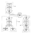
- Enabling method 310 begins with the step ( 311 ) of coding a preamble field comprising a bit pattern having a logical transition every x bit periods (e.g., where x is an integer of at least three for a (0, k) or (1, k) encoded channel, or where x is an integer of at least d+2 for a (d, k) encoded channel where d is greater than 1).
- the preamble may be recorded (step 312 ) to write channel 313 (e.g., the preamble signal may be transmitted by a read/write transducer head to magnetic storage medium 320 ).
- Processing method 330 begins with the step ( 332 ) of reading the preamble field from read channel 331 (e.g., by receiving a preamble signal from magnetic storage medium 320 via a read/write transducer head).
- the preamble field may be processed (step 333 ).
- the processing step may comprise synchronizing the read channel to the bit pattern.
- a preamble pattern for coded data with a period longer than that of the minimum period that can be coded.
- a (0, k) coded data sector conventionally uses the minimal 2T preamble pattern.
- a preamble pattern longer than the 2T pattern may be used.
- One such pattern with a longer period is the 4T pattern. It consists of repetitions of the NRZ bits [00001111] or [11110000]. Because it has a longer period and thus lower frequency, its response is generally higher than that of the 2T pattern, even at relatively high user bit densities.
- processing step 333 may include synchronization step 334 .
- the (d, k) run-length constraint may be a (0, k) run-length constraint (i.e., d, the minimum number of 0s between two is in a sequence, is 0).
- x may be 3 or 4 (e.g., the preamble may comprise 3T or 4T bit patterns, respectively).
- the processing step comprises correlating a characteristic of the bit pattern to the fly height.
- One such circuit is a read-head fly-height measurement circuit that uses the relative amplitudes of the fundamental f and the third harmonic 3 f .
- the response of the 3 f frequency of the 2T pattern at higher user bit density is so low that measurement of its amplitude can be adversely affected by relatively large quantization noise.
- processing step 333 may comprise fly height correlation step 335 .
- Magnetic storage media such as hard disk drives, are typically divided into sectors, where each sector includes a preamble field and a user data field.
- the method further comprises reading a user data field in a data sector, where the data sector comprises the preamble field and the user data field.
- Embedded servo systems generally embed feedback signals for the read/write head positioner inside gaps (wedges) in the data tracks of the disk. This configuration allows the entire set of platters to be used, instead of having to reserve one or two surfaces for the servo's use, which makes more space for data available on the drive.
- the preamble field may be in a servo wedge track.
- the fundamental frequency of the 4T pattern (which has a period of 8 times the bit period) is 1 ⁇ 8T. Its harmonics have a higher response than those of the 2T pattern.
- the third harmonic of the 4T pattern can be measured with reasonably and/or relatively low quantization noise for fly-height detection.
- the use of a longer pattern such as 4T also allows the use of the preamble for fly-height measurement, without any additional overhead (e.g., without using additional dedicated tracks, platters, etc. in a magnetic recording medium). In this way, the preamble pattern can be used for both synchronization and fly-height measurement.
- the 3T preamble pattern generally comprises repetitions of the NRZ bits [000111] or [111000].
- the 3T preamble generally produces a signal with amplitude greater than the amplitude of a 2T preamble signal, but less than the amplitude of a 4T preamble signal.
- more repetitions of the 3T pattern can be written in a fixed preamble length than with the 4T pattern, thus providing more synchronization information than with the 4T pattern.
- the present invention further relates to a magnetic data storage medium comprising (a) data encoded according to a (d, k) run-length constraint, and (b) a preamble field, where the preamble field comprises a bit pattern having a logical transition every x bit periods, where x is an integer of at least 3 when d is 0 or 1, or where x is an integer of at least d+2 when d is greater than 1.
- the (d, k) run-length constraint may be a (0, k) run-length constraint (i.e., d, the minimum number of 0s between two 1s in a sequence, is 0).
- x may be 3 or 4 (e.g., the preamble may comprise 3T or 4T bit patterns, respectively).
- the magnetic medium may further compare at least one data sector comprising the preamble field and a user data field.
- the magnetic medium may comprise at least one servo wedge track that includes the preamble field.
- the invention in another exemplary embodiment, relates to a method of measuring fly height in a magnetic storage system.
- the method generally includes the steps of (a) reading a preamble field from a read channel, wherein the preamble field comprises a repetitive bit pattern wherein the pattern repeats every x′ bit periods, where x′ is an integer of at least four, (b) determining a characteristic of the repetitive bit pattern, and (c) correlating the characteristic to the fly height.
- the invention also relates to a method of enabling such fly height measurement in a magnetic storage system, including the steps of (a) coding a preamble field with a bit pattern wherein the pattern repeats every x′ bit periods, where x′ is an integer of at least four; and (b) recording the preamble to a storage medium.
- the method of enabling may further include the step of transmitting the preamble to a write channel.
- exemplary process 340 shows a method for measuring fly height in a magnetic storage system.
- Process 340 may begin begins with the step ( 342 ) of reading the preamble field from read channel 3411 (e.g., by receiving a preamble signal from storage medium 320 via a read/write transducer head).
- the process may include the step 343 of determining one or more characteristics and/or parameters of the preamble (e.g., the frequency of the preamble, the amplitude of the preamble signal, the amplitude of a harmonic of the preamble signal [e.g., the third harmonic of the preamble signal], etc.).
- the process may include the step 344 of correlating the characteristics and/or parameters with the fly height (e.g., by comparing the amplitude of the preamble signal with the amplitude of a harmonic of the preamble signal).
- the repetitive preamble pattern may have a logical transition every x′/2 bit periods.
- the pattern itself may have exactly one logical transition.
- the pattern may comprise a 3T (e.g., “000111”) or 4T (e.g., “00001111”) pattern.
- the pattern may have more than one logical transition (e.g., “101100”).
- the repetitive preamble pattern generally has a pattern frequency of 1/x′ (e.g., the frequency of a 2T pattern is 1 ⁇ 4T, the frequency of a 3T pattern is 1 ⁇ 6T, the frequency of a 4T pattern is 1 ⁇ 8T, the frequency of a “101100” pattern is 1 ⁇ 6T, etc.).
- the correlating step may comprise comparing amplitude of the pattern frequency to amplitude of a harmonic of the pattern frequency.
- the harmonic may comprise a third harmonic of the pattern frequency. Patterns with more than one transition (e.g., “101100”) generally have more harmonics in the frequency domain, which can help to detect fly height when measuring more than one of the harmonics (e.g., when measuring all of the detectable harmonics).
- the preamble field may be in a servo wedge track.
- the bit density is typically lower than in the user data sector mode.
- the response of the third harmonic is generally higher in servo mode (e.g., because the preamble has a lower frequency).
- a 2T preamble may also be used for fly-height measurement in the servo mode.
- the 2T preamble may be sampled at a higher rate than the nominal bit rate of 1/T.
- the reading step may comprise sampling the read channel at a sampling frequency, where the harmonic is less than half of the sampling frequency.
- the third harmonic can thereby be measured without aliasing with the fundamental frequency of the 2T pattern. Therefore, a 2T servo preamble can be used for both synchronization and fly-height measurement without any extra format loss or additional overhead (e.g., without using additional dedicated tracks, platters, etc. in a magnetic recording medium).
- the encoding may comprise a (0, k) run-length constraint (i.e., d, the minimum number of 0s between two 1s in a sequence, is 0).
- x′ may be 6 or 8 (e.g., the preamble may comprise 3T or 4T bit patterns, respectively, or may comprise a bit pattern with more than one transition in each pattern period).
- the preamble may be in a data sector that also includes a user data field.
- the sampling frequency of a data track is generally 1/T.
- the frequency of the preamble is generally 1 ⁇ 6T.
- the third harmonic of the 3T pattern is generally 1 ⁇ 2T, which is within the Nyquist band of the 1/T sampling frequency. Therefore a 3T repetitive pattern in the preamble of a data sector may be used to measure the fly height (e.g., by comparing the amplitude of the pattern frequency to the amplitude of the third harmonic of the pattern frequency).
- the (magnetic) storage medium may generally be encoded according to a (d, k) run-length constraint may be a (0, k) run-length constraint (i.e., d, the minimum number of 0s between two is in a sequence, is 0).
- x′ may be 6 or 8 (e.g., the preamble may comprise 3T or 4T bit patterns, respectively, or may comprise a bit pattern with more than one transition in each pattern period).
- the present invention relates to a circuit for processing a preamble field in a read channel.
- the read channel is generally encoded according to a (d, k) run-length constraint.
- the circuit generally includes (a) reading logic configured to read the preamble field, where the preamble field comprises a repetitive bit pattern having a logical transition every x bit periods, where x is an integer of at least 3 when d is 0 or 1, or where x is an integer of at least d+2 when d is greater than 1, and (b) processing logic configured to process the repetitive bit pattern.
- the invention further relates to a circuit comprising means for reading the preamble field, where the preamble field comprises a repetitive bit pattern having a logical transition every x bit periods, where x is an integer of at least 3 when d is 0 or 1, or where x is an integer of at least d+2 when d is greater than 1, and (b) means for processing the repetitive bit pattern.
- circuit 350 may include read logic 352 , configured to read a preamble field from read channel 351 (e.g., (e.g., by receiving a preamble signal from storage medium 320 via a read/write transducer head). Circuit 350 may further include processing logic 353 configured to process the repetitive bit pattern of the preamble field.
- read logic 352 configured to read a preamble field from read channel 351 (e.g., (e.g., by receiving a preamble signal from storage medium 320 via a read/write transducer head).
- Circuit 350 may further include processing logic 353 configured to process the repetitive bit pattern of the preamble field.
- the processing logic may comprise synchronization logic configured to synchronize the read channel to the bit pattern.
- the invention further relates to a circuit comprising means for synchronizing the read channel to the bit pattern.
- the processing logic may comprise correlation logic configured to correlate a characteristic of the bit pattern to a fly height of a read/write head above a storage medium.
- the invention further relates to a circuit comprising means for correlating a characteristic of the bit pattern to a fly height of a read/write head above a storage medium.
- the (d, k) run-length constraint may be a (0, k) run-length constraint (i.e., d, the minimum number of 0s between two 1s in a sequence, is 0).
- x may be 3 or 4 (e.g., the preamble may comprise 3T or 4T bit patterns, respectively).
- the preamble may be in a data sector that also contains a user data field. In another specific implementation, the preamble may be in a servo wedge track.
- the invention in another aspect, relates to a circuit for measuring fly height in a magnetic storage system.
- the circuit generally includes (a) reading logic configured to read a preamble field from a read channel, wherein the preamble field comprises a repetitive bit pattern wherein the pattern repeats every x′ bit periods, where x′ is at least four, (b) determination logic configured to determine a characteristic of the repetitive bit pattern, and (c) correlation logic configured to correlate the characteristic to the fly height.
- the invention further relates to a circuit comprising (a) means for reading a preamble field from a read channel, wherein the preamble field comprises a repetitive bit pattern wherein the pattern repeats every x′ bit periods, where x′ is at least four, (b) means for determining a characteristic of the repetitive bit pattern, and (c) means for correlating the characteristic to the fly height.
- the preamble may be in a data sector that also contains a user data field. In another specific implementation, the preamble may be in a servo wedge track.
- the read channel may be encoded according to a (d, k) run-length constraint.
- the (d, k) run-length constraint may be a (0, k) run-length constraint (i.e., d, the minimum number of 0s between two 1s in a sequence, is 0).
- x′ may be 6 or 8 (e.g., the preamble may comprise 3T or 4T bit patterns, respectively, or may comprise a bit pattern with more than one transition in each pattern period).
- the correlation logic may be configured to compare amplitude of the pattern frequency to amplitude of a harmonic of the pattern frequency.
- the harmonic may comprise a third harmonic of the pattern frequency.
- the invention further relates to a circuit comprising means for comparing amplitude of the pattern frequency to amplitude of a harmonic of the pattern frequency.
- the reading logic may be further configured to sample the read channel at a sampling frequency, and wherein the harmonic is less than half of the sampling frequency (e.g., within the Nyquist band of the sampling frequency).
- the invention further relates to a circuit comprising means for sampling the read channel at a sampling frequency, such that the harmonic of the pattern frequency is less than half of the sampling frequency.
- the invention in a further aspect of the invention, relates to a hard disk drive, comprising (a) a magnetic recording medium, (b) a read/write head; and (c) a circuit as described herein configured to r process the read channel and/or measure fly height.
- the systems relate to those that incorporate such a hard drive, or other magnetic recording systems incorporating the circuits and/or methods of the present invention.
- a further aspect of the invention concerns a network, comprising (a) a plurality of the present systems, communicatively coupled to each other; and (b) a plurality of storage or communications devices, wherein each storage or communications device is communicatively coupled to one of the systems.
- the network may be any kind of known network, such as a storage network (e.g., RAID array), Ethernet, or wireless network.
- FIGS. 5A-5G Various exemplary implementations of the present invention are shown in FIGS. 5A-5G .
- the present invention can be implemented in a hard disk drive (HDD) 400 .
- the present invention may implement either or both signal processing and/or control circuits, which are generally identified in FIG. 5A at 402 .
- the signal processing and/or control circuit 402 and/or other circuits (not shown) in the HDD 400 may process data, perform coding and/or encryption, perform calculations, and/or format data that is output to and/or received from a (magnetic) storage medium 406 .
- the HDD 400 may communicate with a host device (not shown) such as a computer, mobile computing devices such as personal digital assistants, cellular phones, media or MP3 players and the like, and/or other devices via one or more wired or wireless communication links 408 .
- the HDD 400 may be connected to memory 409 such as random access memory (RAM), low latency nonvolatile memory such as flash memory, read only memory (ROM), and/or other suitable electronic data storage.
- RAM random access memory
- ROM read only memory
- the present invention can be implemented in a digital versatile disc (DVD) drive 410 .
- the present invention may implement mass data storage of the DVD drive 410 .
- the signal processing and/or control circuit 412 and/or other circuits (not shown) in the DVD 410 may process data, perform coding and/or encryption, perform calculations, and/or format data that is read from and/or data written to an optical storage medium 416 .
- the signal processing and/or control circuit 412 and/or other circuits (not shown) in the DVD 410 can also perform other functions such as encoding and/or decoding and/or any other signal processing functions associated with a DVD drive.
- the DVD drive 410 may communicate with an output device (not shown) such as a computer, television or other device via one or more wired or wireless communication links 417 .
- the DVD 410 may communicate with mass data storage 418 that stores data in a nonvolatile manner.
- the mass data storage 418 may include a hard disk drive (HDD).
- the HDD may have the configuration shown in FIG. 5A .
- the HDD may be a mini HDD that includes one or more platters having a diameter that is smaller than approximately 1.8′′.
- the DVD 410 may be connected to memory 419 such as RAM, ROM, low latency nonvolatile memory such as flash memory and/or other suitable electronic data storage.
- the present invention can be implemented in a high definition television (HDTV) 420 .
- the present invention may implement mass data storage of the HDTV 420 .
- the HDTV 420 receives HDTV input signals in either a wired or wireless format and generates HDTV output signals for a display 426 .
- signal processing circuit and/or control circuit 422 and/or other circuits (not shown) of the HDTV 420 may process data, perform coding and/or encryption, perform calculations, format data and/or perform any other type of HDTV processing that may be required.
- the HDTV 420 may communicate with mass data storage 427 that stores data in a nonvolatile manner such as optical and/or magnetic storage devices. At least one HDD may have the configuration shown in FIG. 5A and/or at least one DVD may have the configuration shown in FIG. 5B .
- the HDD may be a mini HDD that includes one or more platters having a diameter that is smaller than approximately 1.8′′.
- the HDTV 420 may be connected to memory 428 such as RAM, ROM, low latency nonvolatile memory such as flash memory and/or other suitable electronic data storage.
- the HDTV 420 also may support connections with a WLAN via a WLAN network interface 429 .
- the present invention implements mass data storage of the vehicle control system.
- the present invention may implement a powertrain control system 432 that receives inputs from one or more sensors such as temperature sensors, pressure sensors, rotational sensors, airflow sensors and/or any other suitable sensors and/or that generates one or more output control signals such as engine operating parameters, transmission operating parameters, and/or other control signals.
- sensors such as temperature sensors, pressure sensors, rotational sensors, airflow sensors and/or any other suitable sensors and/or that generates one or more output control signals such as engine operating parameters, transmission operating parameters, and/or other control signals.
- the present invention may also be implemented in other control systems 440 of the vehicle 430 .
- the control system 440 may likewise receive signals from input sensors 442 and/or output control signals to one or more output devices 444 .
- the control system 440 may be part of an anti-lock braking system (ABS), a navigation system, a telematics system, a vehicle telematics system, a lane departure system, an adaptive cruise control system, a vehicle entertainment system such as a stereo, DVD, compact disc and the like. Still other implementations are contemplated.
- the powertrain control system 432 may communicate with mass data storage 446 that stores data in a nonvolatile manner.
- the mass data storage 446 may include optical and/or magnetic storage devices (for example, hard disk drives [HDDs] and/or DVDs). At least one HDD may have the configuration shown in FIG. 5A and/or at least one DVD may have the configuration shown in FIG. 5B .
- the HDD may be a mini HDD that includes one or more platters having a diameter that is smaller than approximately 1.8′′.
- the powertrain control system 432 may be connected to memory 447 such as RAM, ROM, low latency nonvolatile memory such as flash memory and/or other suitable electronic data storage.
- the powertrain control system 432 also may support connections with a WLAN via a WLAN network interface 448 .
- the control system 440 may also include mass data storage, memory and/or a WLAN interface (all not shown).
- the present invention can be implemented in a cellular phone 450 that may include a cellular antenna 451 .
- the present invention may implement mass data storage of the cellular phone 450 .
- the cellular phone 450 includes a microphone 456 , an audio output 458 such as a speaker and/or audio output jack, a display 460 and/or an input device 462 such as a keypad, pointing device, voice actuation and/or other input device.
- the signal processing and/or control circuits 452 and/or other circuits (not shown) in the cellular phone 450 may process data, perform coding and/or encryption, perform calculations, format data and/or perform other cellular phone functions.
- the cellular phone 450 may communicate with mass data storage 464 that stores data in a nonvolatile manner such as optical and/or magnetic storage devices (for example, hard disk drives [HDDs] and/or DVDs). At least one HDD may have the configuration shown in FIG. 5A and/or at least one DVD may have the configuration shown in FIG. 5B .
- the HDD may be a mini HDD that includes one or more platters having a diameter that is smaller than approximately 1.8′′.
- the cellular phone 450 may be connected to memory 466 such as RAM, ROM, low latency nonvolatile memory such as flash memory and/or other suitable electronic data storage.
- the cellular phone 450 also may support connections with a WLAN via a WLAN network interface 468 .
- the present invention can be implemented in a set top box 480 .
- the present invention may implement mass data storage of the set top box 480 .
- the set top box 480 receives signals from a source such as a broadband source and outputs standard and/or high definition audio/video signals suitable for a display 488 such as a television and/or monitor and/or other video and/or audio output devices.
- the signal processing and/or control circuits 484 and/or other circuits (not shown) of the set top box 480 may process data, perform coding and/or encryption, perform calculations, format data and/or perform any other set top box function.
- the set top box 480 may communicate with mass data storage 490 that stores data in a nonvolatile manner.
- the mass data storage 490 may include optical and/or magnetic storage devices (for example, hard disk drives [HDDs] and/or DVDs). At least one HDD may have the configuration shown in FIG. 5A and/or at least one DVD may have the configuration shown in FIG. 5B .
- the HDD may be a mini HDD that includes one or more platters having a diameter that is smaller than approximately 1.8′′.
- the set top box 480 may be connected to memory 494 such as RAM, ROM, low latency nonvolatile memory such as flash memory and/or other suitable electronic data storage.
- the set top box 480 also may support connections with a WLAN via a WLAN network interface 496 .
- the present invention can be implemented in a media player 500 .
- the present invention may implement mass data storage of the media player 500 .
- the media player 500 includes a display 507 and/or a user input 508 such as a keypad, touchpad and the like.
- the media player 500 may employ a graphical user interface (GUI) that typically employs menus, drop down menus, icons and/or a point-and-click interface via the display 507 and/or user input 508 .
- GUI graphical user interface
- the media player 500 further includes an audio output 509 such as a speaker and/or audio output jack.
- the signal processing and/or control circuits 504 and/or other circuits (not shown) of the media player 500 may process data, perform coding and/or encryption, perform calculations, format data and/or perform any other media player function.
- the media player 500 may communicate with mass data storage 510 that stores data such as compressed audio and/or video content in a nonvolatile manner.
- the compressed audio files include files that are compliant with MP3 format or other suitable compressed audio and/or video formats.
- the mass data storage may include optical and/or magnetic storage devices (for example, hard disk drives [HDDs] and/or DVDs). At least one HDD may have the configuration shown in FIG. 5A and/or at least one DVD may have the configuration shown in FIG. 5B .
- the HDD may be a mini HDD that includes one or more platters having a diameter that is smaller than approximately 1.8′′.
- the media player 500 may be connected to memory 514 such as RAM, ROM, low latency nonvolatile memory such as flash memory and/or other suitable electronic data storage.
- the media player 500 also may support connections with a WLAN via a WLAN network interface 516 . Still other implementations in addition to those described above are contemplated.
- the present invention provides methods, circuitry, apparatus, and systems for processing a preamble field in a read channel.
- the processing may include synchronization with the read channel and/or fly height measurement.
- the present invention advantageously provides improved resolution of signals resulting from the preamble field(s) and of harmonics of those signals, and thereby enables fly height measurement and improved channel synchronization without consuming dedicated tracks, platters, etc. on a magnetic recording medium.
Abstract
Description
Claims (37)
Priority Applications (1)
| Application Number | Priority Date | Filing Date | Title |
|---|---|---|---|
| US11/453,219 US7715135B1 (en) | 2005-09-20 | 2006-06-13 | Methods, circuits, apparatus, and systems for read channel synchronization and/or fly height measurement |
Applications Claiming Priority (2)
| Application Number | Priority Date | Filing Date | Title |
|---|---|---|---|
| US71894405P | 2005-09-20 | 2005-09-20 | |
| US11/453,219 US7715135B1 (en) | 2005-09-20 | 2006-06-13 | Methods, circuits, apparatus, and systems for read channel synchronization and/or fly height measurement |
Publications (1)
| Publication Number | Publication Date |
|---|---|
| US7715135B1 true US7715135B1 (en) | 2010-05-11 |
Family
ID=42139349
Family Applications (1)
| Application Number | Title | Priority Date | Filing Date |
|---|---|---|---|
| US11/453,219 Active 2028-10-19 US7715135B1 (en) | 2005-09-20 | 2006-06-13 | Methods, circuits, apparatus, and systems for read channel synchronization and/or fly height measurement |
Country Status (1)
| Country | Link |
|---|---|
| US (1) | US7715135B1 (en) |
Cited By (41)
| Publication number | Priority date | Publication date | Assignee | Title |
|---|---|---|---|---|
| US20090161245A1 (en) * | 2007-12-21 | 2009-06-25 | Lsi Corporation | Frequency Domain Approach for Efficient Computation of Fixed-point Equalization Targets |
| US20090268330A1 (en) * | 2008-04-28 | 2009-10-29 | Samsung Electronics Co., Ltd. | Method and apparatus estimating touch-down approach flying height for magnetic head of disk drive |
| US20090323211A1 (en) * | 2008-06-27 | 2009-12-31 | Samsung Electronics Co., Ltd. | New data pattern for fly height measurement |
| US20100053793A1 (en) * | 2008-08-27 | 2010-03-04 | Lsi Corporation | Systems and Methods for Adaptive Write Pre-Compensation |
| US20100053787A1 (en) * | 2008-08-27 | 2010-03-04 | Lsi Corporation | Systems and Methods for On-The-Fly Write Pre-compensation Estimation |
| US20100088357A1 (en) * | 2008-10-08 | 2010-04-08 | Lsi Corporation | Systems and Methods for Memory Efficient Signal and Noise Estimation |
| US20100157768A1 (en) * | 2008-12-18 | 2010-06-24 | Mueller Brian K | Systems and Methods for Generating Equalization Data Using Shift Register Architecture |
| US20100157460A1 (en) * | 2008-12-18 | 2010-06-24 | Lsi Corporation | Systems and Methods for Generating Equalization Data |
| US20100157459A1 (en) * | 2008-12-18 | 2010-06-24 | Lsi Corporation | Systems and Methods for Controlling Data Equalization |
| US20100172046A1 (en) * | 2009-01-02 | 2010-07-08 | Lsi Corporation | Systems and Methods for Equalizer Optimization in a Storage Access Retry |
| US20100177430A1 (en) * | 2007-12-14 | 2010-07-15 | George Mathew | Systems and Methods for Fly-Height Control Using Servo Address Mark Data |
| US20100202082A1 (en) * | 2008-07-28 | 2010-08-12 | Nils Graef | Systems and Methods for Variable Fly Height Measurement |
| US20100271724A1 (en) * | 2009-04-28 | 2010-10-28 | Lsi Corporation | Systems and Methods for Nyquist Tone Harmonic Measurements |
| US20110018748A1 (en) * | 2009-07-27 | 2011-01-27 | Lsi Corporation | Systems and Methods for Two Tier Sampling Correction in a Data Processing Circuit |
| US20110043938A1 (en) * | 2007-12-14 | 2011-02-24 | George Mathew | Systems and Methods for Fly-Height Control Using Servo Data |
| US20110063747A1 (en) * | 2009-09-14 | 2011-03-17 | Lsi Corporation | Systems and Methods for Timing and Gain Acquisition |
| US7929240B2 (en) | 2008-12-18 | 2011-04-19 | Lsi Corporation | Systems and methods for adaptive MRA compensation |
| US7957251B2 (en) | 2009-02-16 | 2011-06-07 | Agere Systems Inc. | Systems and methods for reduced latency loop recovery |
| US7974030B2 (en) | 2008-12-23 | 2011-07-05 | Lsi Corporation | Systems and methods for dibit correction |
| US8175201B2 (en) | 2007-12-21 | 2012-05-08 | Lsi Corporation | Systems and methods for adaptive equalization in recording channels |
| EP2549477A1 (en) * | 2011-07-19 | 2013-01-23 | LSI Corporation | Systems and methods for user data based fly height calculation |
| US8649119B2 (en) | 2011-08-17 | 2014-02-11 | HGST Netherlands B.V. | Measuring variations in head-disk clearance in a hard disk drive |
| US8654466B1 (en) | 2011-11-21 | 2014-02-18 | Western Digital Technologies, Inc. | Calculation of head media separation (HMS) from servo preamble in a hard disk drive |
| US8699159B1 (en) | 2012-06-18 | 2014-04-15 | Western Digital Technologies, Inc. | Reducing effects of wide area track erasure in a disk drive |
| US8762440B2 (en) | 2011-07-11 | 2014-06-24 | Lsi Corporation | Systems and methods for area efficient noise predictive filter calibration |
| US8773807B1 (en) | 2012-07-24 | 2014-07-08 | Western Digital Technologies, Inc. | Disk drive calibrating fly height during startup by reading spacing pattern in servo sectors |
| US8773802B1 (en) | 2010-08-24 | 2014-07-08 | Western Digital Technologies, Inc. | Disk drive resetting fly height reference generated from a degrading calibration track |
| US8824081B1 (en) | 2012-03-13 | 2014-09-02 | Western Digital Technologies, Inc. | Disk drive employing radially coherent reference pattern for servo burst demodulation and fly height measurement |
| US8848776B1 (en) | 2013-03-25 | 2014-09-30 | Lsi Corporation | Systems and methods for multi-dimensional signal equalization |
| US8854752B2 (en) | 2011-05-03 | 2014-10-07 | Lsi Corporation | Systems and methods for track width determination |
| US8879188B1 (en) | 2010-08-23 | 2014-11-04 | Western Digital Technologies, Inc. | Disk drive employing fly height calibration tracks to account for magnetic entropy and thermal decay |
| US8908312B2 (en) | 2012-11-19 | 2014-12-09 | HGST Netherlands B.V. | Dynamic fly height control that is insensitive to off-track motion |
| US8929010B1 (en) | 2013-08-21 | 2015-01-06 | Lsi Corporation | Systems and methods for loop pulse estimation |
| US9025269B1 (en) | 2014-01-02 | 2015-05-05 | Western Digital Technologies, Inc. | Disk drive compensating for cycle slip of disk locked clock when reading mini-wedge |
| US9112538B2 (en) | 2013-03-13 | 2015-08-18 | Avago Technologies General Ip (Singapore) Pte. Ltd. | Systems and methods for loop feedback |
| US9153266B1 (en) * | 2014-09-11 | 2015-10-06 | Western Digital Technologies, Inc. | Data storage device measuring laser protrusion fly height profile |
| US9799358B2 (en) * | 2013-09-25 | 2017-10-24 | Seagate Technolgy Llc | Detection and remediation of head contamination |
| US9916847B1 (en) | 2015-06-04 | 2018-03-13 | Seagate Technology Llc | Magnetic recording device capable of detecting contamination buildup at a head-disk interface |
| US20180198584A1 (en) * | 2017-01-09 | 2018-07-12 | Qualcomm Incorporated | Using sequences of pilot repetitions for receiver adaptation |
| US10147454B1 (en) | 2017-05-15 | 2018-12-04 | Seagate Technology Llc | Heat-assisted magnetic recording device capable of detecting degradation of NFT by measuring back-heat from medium |
| US20230402061A1 (en) * | 2021-01-21 | 2023-12-14 | Sony Group Corporation | Recording medium, recording apparatus, recording method, reproducing apparatus, and reproduction method |
Citations (4)
| Publication number | Priority date | Publication date | Assignee | Title |
|---|---|---|---|---|
| US4146911A (en) * | 1977-12-23 | 1979-03-27 | Burroughs Corporation | Head spacing control |
| US6195025B1 (en) * | 1998-07-13 | 2001-02-27 | International Business Machines Corporation | Method and means for invertibly mapping binary sequences into rate 2/3 (1,K) run-length-limited coded sequences with maximum transition density constraints |
| US6671110B2 (en) * | 2000-02-09 | 2003-12-30 | Hitachi Global Storage Technologies Netherlands B.V. | Method and apparatus for detecting abnormal magnetic head fly height |
| US7136250B1 (en) * | 2003-03-25 | 2006-11-14 | Marvell International Ltd. | Detecting fly height of a head over a storage medium |
-
2006
- 2006-06-13 US US11/453,219 patent/US7715135B1/en active Active
Patent Citations (4)
| Publication number | Priority date | Publication date | Assignee | Title |
|---|---|---|---|---|
| US4146911A (en) * | 1977-12-23 | 1979-03-27 | Burroughs Corporation | Head spacing control |
| US6195025B1 (en) * | 1998-07-13 | 2001-02-27 | International Business Machines Corporation | Method and means for invertibly mapping binary sequences into rate 2/3 (1,K) run-length-limited coded sequences with maximum transition density constraints |
| US6671110B2 (en) * | 2000-02-09 | 2003-12-30 | Hitachi Global Storage Technologies Netherlands B.V. | Method and apparatus for detecting abnormal magnetic head fly height |
| US7136250B1 (en) * | 2003-03-25 | 2006-11-14 | Marvell International Ltd. | Detecting fly height of a head over a storage medium |
Cited By (58)
| Publication number | Priority date | Publication date | Assignee | Title |
|---|---|---|---|---|
| US9305582B2 (en) * | 2007-12-14 | 2016-04-05 | Avago Technologies General Ip (Singapore) Pte. Ltd. | Systems and methods for fly-height control using servo data |
| US8054573B2 (en) * | 2007-12-14 | 2011-11-08 | Lsi Corporation | Systems and methods for fly-height control using servo address mark data |
| US20110043938A1 (en) * | 2007-12-14 | 2011-02-24 | George Mathew | Systems and Methods for Fly-Height Control Using Servo Data |
| US20100177430A1 (en) * | 2007-12-14 | 2010-07-15 | George Mathew | Systems and Methods for Fly-Height Control Using Servo Address Mark Data |
| US8175201B2 (en) | 2007-12-21 | 2012-05-08 | Lsi Corporation | Systems and methods for adaptive equalization in recording channels |
| US7924523B2 (en) | 2007-12-21 | 2011-04-12 | Lsi Corporation | Frequency domain approach for efficient computation of fixed-point equalization targets |
| US20090161245A1 (en) * | 2007-12-21 | 2009-06-25 | Lsi Corporation | Frequency Domain Approach for Efficient Computation of Fixed-point Equalization Targets |
| US20090268330A1 (en) * | 2008-04-28 | 2009-10-29 | Samsung Electronics Co., Ltd. | Method and apparatus estimating touch-down approach flying height for magnetic head of disk drive |
| US7826166B2 (en) * | 2008-06-27 | 2010-11-02 | Samsung Electronics Co., Ltd. | Data pattern for fly height measurement |
| US20090323211A1 (en) * | 2008-06-27 | 2009-12-31 | Samsung Electronics Co., Ltd. | New data pattern for fly height measurement |
| US8098451B2 (en) * | 2008-07-28 | 2012-01-17 | Agere Systems Inc. | Systems and methods for variable fly height measurement |
| US20100202082A1 (en) * | 2008-07-28 | 2010-08-12 | Nils Graef | Systems and Methods for Variable Fly Height Measurement |
| US7859780B2 (en) | 2008-08-27 | 2010-12-28 | Agere Systems Inc. | Systems and methods for on-the-fly write pre-compensation estimation |
| US20100053793A1 (en) * | 2008-08-27 | 2010-03-04 | Lsi Corporation | Systems and Methods for Adaptive Write Pre-Compensation |
| US20100053787A1 (en) * | 2008-08-27 | 2010-03-04 | Lsi Corporation | Systems and Methods for On-The-Fly Write Pre-compensation Estimation |
| US7924518B2 (en) | 2008-08-27 | 2011-04-12 | Lsi Corporation | Systems and methods for adaptive write pre-compensation |
| US9281908B2 (en) | 2008-10-08 | 2016-03-08 | Avago Technologies General Ip (Singapore) Pte. Ltd. | Systems and methods for memory efficient signal and noise estimation |
| US20100088357A1 (en) * | 2008-10-08 | 2010-04-08 | Lsi Corporation | Systems and Methods for Memory Efficient Signal and Noise Estimation |
| US7965467B2 (en) | 2008-12-18 | 2011-06-21 | Lsi Corporation | Systems and methods for generating equalization data |
| US20100157459A1 (en) * | 2008-12-18 | 2010-06-24 | Lsi Corporation | Systems and Methods for Controlling Data Equalization |
| US8154815B2 (en) | 2008-12-18 | 2012-04-10 | Lsi Corporation | Systems and methods for generating equalization data using shift register architecture |
| US20100157460A1 (en) * | 2008-12-18 | 2010-06-24 | Lsi Corporation | Systems and Methods for Generating Equalization Data |
| US7929240B2 (en) | 2008-12-18 | 2011-04-19 | Lsi Corporation | Systems and methods for adaptive MRA compensation |
| US7948702B2 (en) | 2008-12-18 | 2011-05-24 | Lsi Corporation | Systems and methods for controlling data equalization |
| US20100157768A1 (en) * | 2008-12-18 | 2010-06-24 | Mueller Brian K | Systems and Methods for Generating Equalization Data Using Shift Register Architecture |
| US7974030B2 (en) | 2008-12-23 | 2011-07-05 | Lsi Corporation | Systems and methods for dibit correction |
| US7948699B2 (en) | 2009-01-02 | 2011-05-24 | Lsi Corporation | Systems and methods for equalizer optimization in a storage access retry |
| US20100172046A1 (en) * | 2009-01-02 | 2010-07-08 | Lsi Corporation | Systems and Methods for Equalizer Optimization in a Storage Access Retry |
| US7957251B2 (en) | 2009-02-16 | 2011-06-07 | Agere Systems Inc. | Systems and methods for reduced latency loop recovery |
| US20100271724A1 (en) * | 2009-04-28 | 2010-10-28 | Lsi Corporation | Systems and Methods for Nyquist Tone Harmonic Measurements |
| US7872821B2 (en) * | 2009-04-28 | 2011-01-18 | Lsi Corporation | Systems and methods for Nyquist tone harmonic measurements |
| US20110018748A1 (en) * | 2009-07-27 | 2011-01-27 | Lsi Corporation | Systems and Methods for Two Tier Sampling Correction in a Data Processing Circuit |
| US7969337B2 (en) | 2009-07-27 | 2011-06-28 | Lsi Corporation | Systems and methods for two tier sampling correction in a data processing circuit |
| US8139305B2 (en) | 2009-09-14 | 2012-03-20 | Lsi Corporation | Systems and methods for timing and gain acquisition |
| US20110063747A1 (en) * | 2009-09-14 | 2011-03-17 | Lsi Corporation | Systems and Methods for Timing and Gain Acquisition |
| US8879188B1 (en) | 2010-08-23 | 2014-11-04 | Western Digital Technologies, Inc. | Disk drive employing fly height calibration tracks to account for magnetic entropy and thermal decay |
| US8773802B1 (en) | 2010-08-24 | 2014-07-08 | Western Digital Technologies, Inc. | Disk drive resetting fly height reference generated from a degrading calibration track |
| US8854752B2 (en) | 2011-05-03 | 2014-10-07 | Lsi Corporation | Systems and methods for track width determination |
| US8762440B2 (en) | 2011-07-11 | 2014-06-24 | Lsi Corporation | Systems and methods for area efficient noise predictive filter calibration |
| EP2549477A1 (en) * | 2011-07-19 | 2013-01-23 | LSI Corporation | Systems and methods for user data based fly height calculation |
| US8649119B2 (en) | 2011-08-17 | 2014-02-11 | HGST Netherlands B.V. | Measuring variations in head-disk clearance in a hard disk drive |
| US8654466B1 (en) | 2011-11-21 | 2014-02-18 | Western Digital Technologies, Inc. | Calculation of head media separation (HMS) from servo preamble in a hard disk drive |
| US8824081B1 (en) | 2012-03-13 | 2014-09-02 | Western Digital Technologies, Inc. | Disk drive employing radially coherent reference pattern for servo burst demodulation and fly height measurement |
| US8699159B1 (en) | 2012-06-18 | 2014-04-15 | Western Digital Technologies, Inc. | Reducing effects of wide area track erasure in a disk drive |
| US8773807B1 (en) | 2012-07-24 | 2014-07-08 | Western Digital Technologies, Inc. | Disk drive calibrating fly height during startup by reading spacing pattern in servo sectors |
| US8908312B2 (en) | 2012-11-19 | 2014-12-09 | HGST Netherlands B.V. | Dynamic fly height control that is insensitive to off-track motion |
| US9112538B2 (en) | 2013-03-13 | 2015-08-18 | Avago Technologies General Ip (Singapore) Pte. Ltd. | Systems and methods for loop feedback |
| US8848776B1 (en) | 2013-03-25 | 2014-09-30 | Lsi Corporation | Systems and methods for multi-dimensional signal equalization |
| US8929010B1 (en) | 2013-08-21 | 2015-01-06 | Lsi Corporation | Systems and methods for loop pulse estimation |
| US9799358B2 (en) * | 2013-09-25 | 2017-10-24 | Seagate Technolgy Llc | Detection and remediation of head contamination |
| US9025269B1 (en) | 2014-01-02 | 2015-05-05 | Western Digital Technologies, Inc. | Disk drive compensating for cycle slip of disk locked clock when reading mini-wedge |
| US9153266B1 (en) * | 2014-09-11 | 2015-10-06 | Western Digital Technologies, Inc. | Data storage device measuring laser protrusion fly height profile |
| US9916847B1 (en) | 2015-06-04 | 2018-03-13 | Seagate Technology Llc | Magnetic recording device capable of detecting contamination buildup at a head-disk interface |
| US20180198584A1 (en) * | 2017-01-09 | 2018-07-12 | Qualcomm Incorporated | Using sequences of pilot repetitions for receiver adaptation |
| US10727994B2 (en) * | 2017-01-09 | 2020-07-28 | Qualcomm Incorporated | Using sequences of pilot repetitions for receiver adaptation |
| US10147454B1 (en) | 2017-05-15 | 2018-12-04 | Seagate Technology Llc | Heat-assisted magnetic recording device capable of detecting degradation of NFT by measuring back-heat from medium |
| US10482908B2 (en) | 2017-05-15 | 2019-11-19 | Seagate Technology Llc | Performance monitoring of a near-field transducer of a heat-assisted magnetic recording slider |
| US20230402061A1 (en) * | 2021-01-21 | 2023-12-14 | Sony Group Corporation | Recording medium, recording apparatus, recording method, reproducing apparatus, and reproduction method |
Similar Documents
| Publication | Publication Date | Title |
|---|---|---|
| US7715135B1 (en) | Methods, circuits, apparatus, and systems for read channel synchronization and/or fly height measurement | |
| US7679852B2 (en) | Adjustment of read/write clock edge timing | |
| JPH11185210A (en) | Magnetic disk device and error correcting method for the same | |
| US7583467B2 (en) | Hard disk drive apparatus, method to control flying on demand of hard disk drive apparatus using thermal asperity signal, and recording media for computer program thereof | |
| JP2007042178A (en) | Sector format setting processing method of disk storage, and disk storage | |
| US7525747B2 (en) | Data storage device, data storage control circuit, and control method for magnetic disk drive | |
| JP2007141305A (en) | Magnetic disk drive | |
| CN1988000A (en) | Disk drive and control method in disk drive | |
| JP3446289B2 (en) | Disk drive | |
| KR100712503B1 (en) | Method for generating servo data of harddisk drive and method of self servo recording using thereof | |
| US9001443B1 (en) | Method and system for testing a controller of a hard disk drive | |
| JP4211977B2 (en) | Magnetic recording apparatus, magnetic recording medium, and magnetic recording method | |
| US7031091B2 (en) | Magnetic recording apparatus and method of writing data at low temperature | |
| JP2003228927A (en) | Magnetic disk device magnetic recording medium, and servo write system | |
| US10803887B2 (en) | Magnetic disk drive and recording method for magnetic disk drive | |
| US7663832B2 (en) | Method of compensating for track zero position in reference servo track copying system and disc drive using the same | |
| JP5064661B2 (en) | Sector pulse timing control method, servo gate pulse timing control method, and disk drive | |
| KR100564624B1 (en) | Method for designing write and read frequency in data storage system and disk drive using the same | |
| JP2006164448A (en) | Disk device and its control method | |
| JP2005038588A (en) | Method and device for determining sector block size by using existing control signal, and program storage | |
| US6999259B2 (en) | Master disc and method of manufacturing the same | |
| US7667910B2 (en) | Magnetic disk drive, servo writer, self-servo writer and methods for use therewith | |
| JP2008052898A (en) | Method to correct phase difference of data sector due to rotational slip of disk, and disk drive apparatus | |
| US7253979B2 (en) | Method and device for data read/write, recording medium, and program product | |
| KR100543657B1 (en) | Hard disk drive head high-fly write prevention device and method |
Legal Events
| Date | Code | Title | Description |
|---|---|---|---|
| AS | Assignment |
Owner name: MARVELL INTERNATIONAL LTD.,BERMUDA Free format text: ASSIGNMENT OF ASSIGNORS INTEREST;ASSIGNOR:MARVELL SEMICONDUCTOR, INC.;REEL/FRAME:017978/0004 Effective date: 20060613 Owner name: MARVELL SEMICONDUCTOR, INC.,CALIFORNIA Free format text: ASSIGNMENT OF ASSIGNORS INTEREST;ASSIGNORS:SUTARDJA, PANTAS;DOAN, TOAI;WU, ZINING;AND OTHERS;REEL/FRAME:017978/0008 Effective date: 20060612 |
|
| STCF | Information on status: patent grant |
Free format text: PATENTED CASE |
|
| FPAY | Fee payment |
Year of fee payment: 4 |
|
| MAFP | Maintenance fee payment |
Free format text: PAYMENT OF MAINTENANCE FEE, 8TH YEAR, LARGE ENTITY (ORIGINAL EVENT CODE: M1552) Year of fee payment: 8 |
|
| AS | Assignment |
Owner name: CAVIUM INTERNATIONAL, CAYMAN ISLANDS Free format text: ASSIGNMENT OF ASSIGNORS INTEREST;ASSIGNOR:MARVELL INTERNATIONAL LTD.;REEL/FRAME:052918/0001 Effective date: 20191231 |
|
| AS | Assignment |
Owner name: MARVELL ASIA PTE, LTD., SINGAPORE Free format text: ASSIGNMENT OF ASSIGNORS INTEREST;ASSIGNOR:CAVIUM INTERNATIONAL;REEL/FRAME:053475/0001 Effective date: 20191231 |
|
| MAFP | Maintenance fee payment |
Free format text: PAYMENT OF MAINTENANCE FEE, 12TH YEAR, LARGE ENTITY (ORIGINAL EVENT CODE: M1553); ENTITY STATUS OF PATENT OWNER: LARGE ENTITY Year of fee payment: 12 |