US7471484B2 - Patterned medium and recording head - Google Patents
Patterned medium and recording head Download PDFInfo
- Publication number
- US7471484B2 US7471484B2 US10/863,648 US86364804A US7471484B2 US 7471484 B2 US7471484 B2 US 7471484B2 US 86364804 A US86364804 A US 86364804A US 7471484 B2 US7471484 B2 US 7471484B2
- Authority
- US
- United States
- Prior art keywords
- data
- trough
- areas
- recording head
- read
- Prior art date
- Legal status (The legal status is an assumption and is not a legal conclusion. Google has not performed a legal analysis and makes no representation as to the accuracy of the status listed.)
- Expired - Fee Related, expires
Links
Images


Classifications
-
- G—PHYSICS
- G11—INFORMATION STORAGE
- G11B—INFORMATION STORAGE BASED ON RELATIVE MOVEMENT BETWEEN RECORD CARRIER AND TRANSDUCER
- G11B5/00—Recording by magnetisation or demagnetisation of a record carrier; Reproducing by magnetic means; Record carriers therefor
- G11B5/62—Record carriers characterised by the selection of the material
- G11B5/73—Base layers, i.e. all non-magnetic layers lying under a lowermost magnetic recording layer, e.g. including any non-magnetic layer in between a first magnetic recording layer and either an underlying substrate or a soft magnetic underlayer
- G11B5/7368—Non-polymeric layer under the lowermost magnetic recording layer
- G11B5/7369—Two or more non-magnetic underlayers, e.g. seed layers or barrier layers
-
- G—PHYSICS
- G11—INFORMATION STORAGE
- G11B—INFORMATION STORAGE BASED ON RELATIVE MOVEMENT BETWEEN RECORD CARRIER AND TRANSDUCER
- G11B5/00—Recording by magnetisation or demagnetisation of a record carrier; Reproducing by magnetic means; Record carriers therefor
- G11B5/62—Record carriers characterised by the selection of the material
- G11B5/73—Base layers, i.e. all non-magnetic layers lying under a lowermost magnetic recording layer, e.g. including any non-magnetic layer in between a first magnetic recording layer and either an underlying substrate or a soft magnetic underlayer
- G11B5/739—Magnetic recording media substrates
- G11B5/73911—Inorganic substrates
- G11B5/73917—Metallic substrates, i.e. elemental metal or metal alloy substrates
- G11B5/73919—Aluminium or titanium elemental or alloy substrates
Definitions
- This invention relates to a patterned medium having land areas for storing data and trough areas for inhibiting storage of data, and to use of the patterned medium with a read wide/write narrow recording head.
- a magnetic disk drive is a digital data storage device that stores digital data on magnetic medium known as a disk.
- the disk in general, comprises a plurality of tracks for storing the digital data. Data is stored on the tracks of the disk in the form of magnetic polarity transitions induced into a magnetic layer covering the disk.
- a transducer known as a recording head
- the head can be used to transfer data to the track (during a write operation) or to transfer data from the track (during a read operation).
- a write current is delivered to the centered head to create an alternating magnetic field in a lower portion of the head that induces magnetic polarity transitions onto the track.
- the centered head senses magnetic fields emanating from the magnetic polarity transitions on the moving track to create an analog read signal representative of the data thereon.
- the recording head may be a dual element head having a read element for performing a read operation and a write element for performing a write operation. It is known to make the read element wider than the write element provided that the write element contains erase bands on its edges to “erase” old data from a track on the disk and thereby prevent the read element from sensing that old data.
- This configuration is described in U.S. Pat. No. 5,940,250 (McNeil et al.), the contents of which are hereby incorporated by reference into this application as if set forth herein in full.
- the invention is a magnetic recording system that includes a patterned medium comprised of land areas and trough areas, a write element which writes the data to the patterned medium, and a read element which reads the data from the patterned medium.
- the read element is wider than the write element.
- the land areas store data and the trough areas inhibit storage of data. That is, the troughs prevent old data from being written outside of the land areas, making it possible to increase the width of the read element without causing the read element to sense out-of-track noise.
- Increasing the width of the read element can provide significant signal-to-noise advantages in the system.
- the read element and the write element may be part of a recording head that flies over the patterned medium during reading and writing.
- the trough areas may have a depth relative to the recording head that is sufficient to prevent magnetic writing of data to the trough areas.
- the patterned medium may be made of a polymer layer disposed on a substrate, which layer defines the land areas and the trough areas. Examples of substrates include glass, NiP-clad aluminum alloy substrates, glass-ceramic substrates, and titanium substrates.
- the polymer layer also includes a magnetic layer.
- the read element may have a read width that is greater than the write width of the write element.
- the patterned medium may include a rotatable magnetic disk having tracks that store the data.
- the tracks may be concentric, spiral, or of any other configuration.
- the tracks may include the land areas.
- the tracks may be separated on the rotatable magnetic disk by the trough areas.
- the land areas may include data islands that are isolated from one another by the trough areas. Each of the data islands may be capable of storing one bit.
- the invention is directed to a disk drive that includes a magnetic disk having a plurality of tracks which store data.
- the tracks include land areas for storing the data and trough areas which substantially isolate the land areas from one another.
- the disk drive also includes a recording head which transfers data to and from the magnetic disk.
- the recording head includes a write element and a read element.
- the read element has a width that is greater than a width of the write element.
- An actuator arm may be included in the disk drive for positioning the head over the disk.
- the recording head may fly over the disk during reading and writing.
- the trough areas may have a depth relative to the recording head that is sufficient to prevent magnetic writing of data to the trough areas.
- the magnetic disk may be a patterned medium comprised of a polymer layer disposed on a substrate. The polymer layer defines the land areas and the trough areas and includes a magnetic layer thereon.
- the land areas on the tracks may include data islands which are isolated from one another by the trough areas. Each of the data islands may be capable of storing one bit.
- the tracks may have a different density at an inner diameter of the magnetic disk than at an outer diameter of the magnetic disk.
- the trough areas may function as erase bands during writing on the magnetic disk.
- the invention is directed to a patterned magnetic storage medium.
- the storage medium includes a substrate and a layer formed on the substrate.
- the layer defines land areas and trough areas.
- the land areas store data and the trough areas inhibit storage of data between the land areas.
- This aspect of the invention may include one or more of the following features.
- the land areas may be raised higher than the trough areas relative to the substrate.
- the trough areas may have a depth relative to the land areas that is sufficient to prevent magnetic writing of data to the trough areas.
- the land areas may include data islands that are isolated from one another by the trough areas. Each of the data islands may be capable of storing one bit.
- the land areas may be concentric or spiral tracks and the trough areas may separate the tracks from one another.
- the trough areas may function as erase bands for preventing writing of data between the land areas.
- the substrate may be glass, a NiP-clad aluminum alloy substrate, a glass-ceramic substrate, and/or a titanium substrate and the layer may be polymer having a magnetic layer deposited thereon.
- the invention is directed to an apparatus that includes storing means for storing data magnetically in data tracks.
- the data tracks are separated by erase bands that are physically stamped onto the storing means.
- the apparatus also includes a writing means which writes data to the storing means.
- Reading means reads data from the storing means.
- the reading means has a width that is greater than a width of the writing means.
- the erase bands may be troughs that are formed on the storing means between the data tracks.
- the storing means may be a patterned medium formed of a polymer layer disposed on a substrate.
- the polymer layer may include the data tracks and the erase bands and may have a magnetic layer deposited thereon.
- the reading means and the writing means may be part of a recording means that flies over the storing means during reading and writing.
- the erase bands may be troughs that have a depth relative to the recording means that is sufficient to prevent magnetic writing of data to the troughs.
- the data tracks may include sequences of data islands separated by troughs.
- the invention is directed to a magnetic recording system which includes a patterned medium comprised of land areas and trough areas.
- the land areas store data and the trough areas inhibit storage of data.
- the system includes a recording head which reads and writes data to the land areas of the patterned medium.
- the recording head has a read element.
- the read element has a width that is greater than a width of the land areas.
- the recording head may include a write element having a width that is less than the width of the read element and that is greater than the width of the land areas.
- the trough areas may have a depth relative to the recording head that is sufficient to prevent magnetic writing of data to the trough areas.
- the patterned medium may include a polymer layer disposed on a substrate. The polymer layer may define the land areas and the trough areas and may have a magnetic layer deposited thereon.
- the patterned medium may be a rotatable magnetic disk having tracks which store data.
- the concentric tracks may be the land areas.
- the tracks may be separated on the rotatable magnetic disk by the trough areas.
- the land areas may include data islands which are isolated from one another by the trough areas. Each of the data islands may be capable of storing a block of data.
- a block of data may be one bit.
- the invention is directed to a magnetic recording medium that includes land areas which store data and trough areas which store servo information. Storing servo information in the trough areas makes it possible to provide continuous servo to a head scanning the recording medium, while at the same time increasing the amount of medium space available to store substantive data.
- This aspect may include one or more of the following.
- the data in the land areas may be at a higher frequency than the servo information in the trough areas.
- the trough areas may include steps having a height that is less than the land areas relative to the troughs. The steps may comprise the servo information.
- a land area may be a data track; a first trough may border one side of the land area; and a second trough may border another side of the land area.
- the servo information in the first trough may be at a different frequency than the servo information in the second trough.
- the troughs may include at least one of servo signals and grey code.
- the land and trough areas may be alternating concentric or spiral tracks.
- the land areas may include data islands isolated from one another by additional trough areas. Each of the data islands may be capable of storing a block of data.
- the block of data may be one bit.
- the invention is directed to a magnetic recording system that includes a patterned medium comprised of land areas and trough areas.
- the land areas store data and the trough areas store servo information.
- the system includes a recording head that reads and writes data to the land areas of the patterned medium and reads servo information from the trough areas.
- the recording head may include a read element and a write element.
- the read element may have a width that is greater than a width of the write element.
- the data in the land areas may be at a higher frequency than the servo information in the trough areas.
- the recording head may be positioned sufficiently close to the land areas to read higher-frequency data and sufficiently close to the trough areas to read lower-frequency servo information.
- the trough areas may include steps, which have a height that is less than the land areas relative to the troughs. The steps may comprise the servo information.
- a land area may include a data track; a first trough may border one side of the land area; and a second trough may border another side of the land area.
- the servo information in the first trough may be at a different frequency than the servo information in the second trough.
- the troughs may include at least one of servo information and grey code.
- the land areas and trough areas may be alternating concentric or spiral tracks.
- the land areas may include data islands which are isolated from one another by additional trough areas. Each of the data islands may be capable of storing a block of data.
- the block of data may be one bit.
- the patterned medium may be a rotatable magnetic disk having alternating tracks which comprise the lands and troughs.
- the patterned medium may contain a data sector which stores phase locked loop information.
- the magnetic recording system may include a lowpass filter which receives the data and servo information and outputs the servo information, and a highpass filter which receives the data and servo information and outputs the data.
- the invention is directed to a method of accessing data.
- the method includes moving a recording head over a patterned medium comprised of land areas and trough areas, the land areas storing data and the trough areas storing servo information, transferring data on a land area, reading servo information from trough areas at the same time as transferring the data, and using the servo information to move the recording head relative to the land area.
- This aspect may include one or more of the following features.
- the land area may include a data track; a first trough may border one side of the land area; and a second trough may border another side of the land area.
- the servo information is used to move the recording head by comparing servo information from the first trough to servo information from the second trough and re-positioning the recording head based on the comparison.
- the servo information in the first trough may be at a different frequency than the servo information in the second trough.
- the recording head may include a read element and a write element, the read element having a width that is greater than a width of the write element.
- FIG. 1 is a diagram illustrating an offset between a read element and a write element in a dual element recording head and the effect the offset has when positioning the head over various tracks.
- FIGS. 2A , 2 B and 2 C illustrate a write operation to a track, a second subsequent write operation to the same track, and using a dual element recording head having a read wide/write narrow architecture.
- FIG. 3 is a cross-sectional, side, perspective view of a patterned medium and a write element of a read wide/write narrow dual element recording head.
- FIG. 4 is a cross-sectional, side view of the patterned medium, illustrating components that make up the patterned medium.
- FIG. 5 is a top view of the patterned medium and the relationship of the patterned medium to a read element and a write element of a dual element recording head.
- FIG. 6 is a cross-sectional, side, perspective view of a patterned medium that contains data islands in its data tracks.
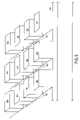
- FIG. 7 is a top view of a magnetic recording medium comprised of lands for storing data and troughs having steps for storing servo information.
- FIG. 8 is a cross-sectional, side view of the magnetic recording medium of FIG. 7 .
- FIG. 9 is a block diagram of a magnetic recording system that includes a magnetic recording medium having servo information written into troughs of a patterned medium.
- a recording head is maintained in a centered position above a desired track in a process known as track following.
- this process entails centering the write element during a write operation and centering the read element during a read operation.
- the write element of a dual element head is not always centered on a track when the corresponding read element is centered on the track and vice versa.
- FIG. 1 is a top view illustrating a dual element recording head 16 in various positions above a disk 18 . That is, the figure shows recording head 16 above a first track 20 at the outer diameter (O.D.) of disk 18 , above a second track 22 at the inner diameter (I.D.) of disk 18 , and above a third track 24 at a middle diameter (M.D.) of disk 18 . It should be appreciated that three heads are shown in FIG. 1 for comparison purposes only and that, in general, there will be only one head above each disk surface in the drive. It should also be appreciated that the dimensions illustrated in FIG. 1 are exaggerated for illustration purposes.
- recording head 16 is located at the end of an actuator arm 40 that carries recording head 16 above the surface of disk 18 .
- Actuator arm 40 pivots about a pivot point (not shown) so that the angle that arm 40 makes with each track centerline varies across the surface of the disk. This angle is known as the skew angle.
- Recording head 16 includes a read (RD) element 26 having a center defined by centerline 30 and a separate write (WR) element 28 having a center defined by centerline 32 .
- read element centerline 30 is purposely offset in a lateral direction from write element centerline 32 .
- read element 26 and write element 28 are usually not centered on the same track of disk 18 at the same time. That is, if one of the two elements is centered on a particular track, the other is generally off-center by a certain amount.
- a servo system (not shown) is generally implemented that uses feedback information, read from disk 18 by read element 26 , to properly position recording head 16 . Because read element 26 provides the feedback information to the servo system, the system will center read element 26 , rather than write element 28 , if additional information is not supplied to the servo system. During a write operation, therefore, a compensation value is delivered to the servo system to center write element 28 , if additional information is not supplied to the servo system. The compensation value delivered to the servo system generally varies across the surface of the disk based on the combined effect of the skew angle and the offset between the elements.
- TMR track misregistration
- the TMR is a statistically derived value based on past observation in similar or identical disk drive systems.
- MR read elements include a small piece of magnetoresistive material having a variable resistivity that changes based on an applied magnetic field. That is, as the magnetic field applied to the material increases, the resistivity of the material, in general, decreases.
- the MR material is held near the desired track as a substantially constant current is run through the material.
- the magnetic field variations produced by the magnetic transitions on the rotating track change the resistance of the magnetic material, resulting in a variable voltage across the material that is representative of the data stored on the disk (i.e., a read signal).
- MR read elements have gained much popularity in recent years as they typically generate read signals having considerably higher voltage than those generated by inductive read elements.
- Dual element heads of the past utilized a write wide/read narrow approach. It has been determined, however, that this approach results in problems associated with a nonlinear servo position signal transfer function. Accordingly, read wide/write narrow dual element heads were developed. In a read wide/write narrow dual element recording head, the width of the read element exceeds the width of the write element.
- FIGS. 2A-2C illustrate the use, with a non-patterned medium, of a dual element recording head 42 having a read wide/write narrow configuration.
- a non-patterned medium is a recording medium, such as a magnetic disk, that is substantially smooth on its recording surface. That is, a non-patterned medium does not contain the physically imprinted land and trough areas described below.
- Dual element recording head 42 includes a write element 44 having a write width (W) and read element 46 having a read element width (R), where the read width is greater than the write width.
- Recording head 42 also includes a read element centerpoint 48 and a write element centerpoint 50 that are substantially laterally offset from one another with respect to direction of travel 52 of the recording head.
- Boundary lines 54 A, 54 B represent the TMR boundaries for data track 56 .
- write element 44 includes erase bands 58 A and 58 B for creating magnetic erase bands on either side of the data written onto track 56 by write element 44 .
- the magnetic erase bands are formed of magnetic flux at the edges of write element 44 . This flux is inherent in all write elements and may be increased or decreased to increase or decrease, respectively, the size of the magnetic erase bands. Although the operation of the magnetic erase bands is not strictly necessary for the present invention, a description thereof may aid in understanding benefits provided by the patterned media described below.
- FIG. 2A illustrates a first write operation to track 56 using dual element recording head 42 .
- write element 44 is centered on the left TMR boundary 54 A and therefore writes first data 60 off-center to the left on track 56 .
- Magnetic erase bands 58 A, 58 B of write element 42 create first erase strips 62 A, 62 B.
- erase strips 62 A, 62 B comprise areas of track 56 where no readable data is stored.
- FIG. 2B illustrates a second, subsequent write operation to track 56 .
- write element 44 is centered on right TMR boundary line 54 B and, therefore, writes second data 66 on track 56 off-center to the right.
- erase bands 58 A, 58 B of write element 44 create second erase strips 68 A, 68 B on either side of second data 66 during the second write operation.
- second erase strip 68 A on the left of data 66 erases any of first data 60 that would otherwise have remained on track 56 after the second write operation.
- read element 46 will not sense first data 60 on track 56 .
- a patterned medium is a magnetic storage device, such as a magnetic disk, that contains land areas (“lands”) and trough areas (“troughs”).
- lands 70 70 a - 70 c
- troughs 74 74 a , 74 b
- patterned medium 72 is a magnetic disk comprised of a substrate 76 and a polymer layer 78 disposed atop the substrate.
- a polymer that may be used is plastic; however, other types of polymers may be used instead of, or in addition to, plastic.
- a layer may be used that is comprised of a glazing compound containing silica that is processed in its uncured state and subsequently cured at a high temperature.
- substrate 76 examples include, but are not limited to, glass substrates, NiP-clad aluminum alloy substrates, glass-ceramic substrates, and titanium substrates.
- a magnetic layer (not shown) is deposited over the polymer (or silica/Sol-Gel) layer, either before or after stamping of the pattern.
- the land/trough pattern is stamped onto layer 78 of the medium using a mold that holds an inverse of the land/trough pattern.
- the troughs have a depth relative to the recording head and/or the lands that is sufficient to inhibit storage of data in the troughs at the frequency that the data is written.
- the read wide/write narrow recording head is positioned over the lands such that the lands are substantially covered by both the read and write elements.
- the read element is wider than the write element and the write element is at least as wide as the lands and may be wider.
- the recording head “flies”, i.e., moves, over the patterned medium.
- the troughs are sufficiently far from the recording head to inhibit, and preferably to prevent, writing of data inside the troughs. That is, the troughs are far enough away from the recording head to prevent the flux transitions caused by the write element from affecting the magnetic polarity of the areas of the medium defined by the troughs.
- the lands are sufficiently close to the recording head to permit magnetic writing of data thereon.
- the lands constitute the data tracks and the troughs constitute effective erase bands.
- the lands and troughs may be formed as alternating concentric circles (taking into account any servo spokes formed onto the magnetic disk).
- the troughs isolate the lands (i.e., the data tracks) from one another, resulting in data tracks that are defined clearly both physically and magnetically.
- the lands and troughs may be alternated spirals.
- Other track configurations also may be used.
- FIG. 5 shows a top view of the patterned medium of FIGS. 3 and 4 .
- a recording head 80 containing a read element 82 and a write element 84 , is positioned over a land 70 a (a data track).
- write element 84 writes data to the land. Data is not, however, written to troughs 74 a and 74 b that are adjacent to land 70 a because write element 84 is positioned vertically (arrow 73 in FIG. 3 ) too far above the troughs to induce magnetic transitions in the troughs at the frequency at which the data is written.
- constraints for the width 88 of read element 82 and the width 90 of write element 84 are determined as follows.
- the width of the read element should not be less than the track width, i.e., R TW.
- the read element TMR is the amount of TMR that may occur with respect to read element 82 .
- Squeeze (SQ) is the amount by which the gap between adjacent tracks is reduced when write element 84 extends beyond the width TW of track 70 and into trough 74 a .
- Overshoot is a constant that is determined empirically based on parameters of the disk drive, and especially by the servo bandwidth.
- the read width of the read element can be increased significantly relative to read elements used with non-patterned media.
- the troughs prevent old data from being written outside of the data track, making it possible to increase the width of the read element without fear of the read element sensing substantial amounts of old data.
- the width of the read element can be more than doubled, from 0.10 microns ( ⁇ m) to 0.22 ⁇ m.
- Increasing the width of the read element also provides signal-to-noise (SNR) ratio advantages. That is, the amount of valid data increases relative to noise from, e.g., old data. For example, it is possible to obtain a six (6) decibel (db) advantage in SNR using a patterned medium and read wide/write narrow recording head.
- SNR signal-to-noise
- the invention is not limited to the above embodiments.
- the data tracks on the patterned medium may have the same or a different track or bit density at an inner diameter of the magnetic disk than at an outer diameter of the magnetic disk.
- the data tracks may have a higher density at the inner diameter than at the outer diameter, i.e., Ts may vary.
- the data tracks may include data “islands”, as shown in FIG. 6 .
- These data islands 100 each hold a block of data, which may be one bit or multiple bits, and are isolated/separated from one another by troughs 102 within the data track itself.
- the troughs 102 between data islands 100 have a depth relative to the recording head and/or data islands that is sufficient to prevent magnetic writing of data to the trough areas 102 (the depth of troughs 74 and 102 need not be the same).
- This configuration provides an added benefit in that it reduces the amount of noise (e.g., noise between tracks) that is sensed by the read element.
- Servo information may also be stored on the lands.
- the servo information may be stored on the lands using servo bursts at the start of each sector of a magnetic disk.
- the servo information may be recorded onto two or more sub-tracks (e.g., portions of tracks 70 a , 70 b and/or 70 c ) in a specific sector of the magnetic medium.
- the servo information may be stored on the “data islands” and, in fact, may be defined by the frequency and positioning of the data islands themselves.
- the troughs of the patterned medium may contain data, such as servo information.
- the servo information may be written to the bottom surface (or “floor”) of the troughs (as magnetic transitions) at a lower frequency than the data written to the lands.
- the servo information may be written at 1 MegaHertz (MHz) and the data on the lands may be written at 19 to 250 MHz. Writing the data and servo at these or other frequencies allows a read element, such the read element on read wide/write narrow recording head 80 , to sense both data and servo information.
- the recording head is able to sense high-density data at a close distance.
- the recording head is also able to sense lower-density data at a farther distance. Accordingly, the data on the lands, which is closer to the recording head, can be written at a high density and the servo information in the troughs, which is farther away from the recording head, can be written at a lower density.
- the recording head can sense both simultaneously at the same flight height.
- the read element is wider than the land and, accordingly, extends over the lands and into the troughs on either side of the land, allowing the read element to sense both the data and servo information.
- the equation that governs the readability of data relative to the height of the recording head above the recording medium is called the Wallace equation.
- the Wallace equation is as follows:
- FH ⁇ 2 ⁇ ⁇ ⁇ l n ⁇ ( V l V h ) .
- FH the flying height of the recording head, i.e., the distance above the recording medium
- ⁇ is the wavelength in distance between two magnetic transitions that define data
- V 1 is the amplitude of the low flying height of the read element above the data magnetic transitions on the recording medium of the lands
- V h is the amplitude of the high flying height of the read element above the servo magnetic transitions in the troughs
- ln is the natural logarithm function.
- the flying height (FH) that enables the read element to read low frequency magnetic transitions in the troughs is determined by solving the Wallace equation.
- the Wallace equation may also be used to confirm that the read element is able to sense the high frequency magnetic transitions (i.e., the data) on the lands.
- the write element will not be able to write data in the troughs. As a result, the troughs are still able to act as effective erase bands.
- patterned steps may be physically formed in the trough.
- the servo information includes the patterned steps, which create low frequency signals by the abrupt changes in magnetization created by the steps themselves.
- FIG. 7 shows an example of using patterned steps to store servo information (or even other data) in the troughs of a patterned magnetic recording medium 110 .
- the lands and troughs comprise alternating concentric tracks of a magnetic disk; however, the invention is not limited as such.
- the lands and troughs may be spirals or have any other configuration.
- Lands 112 a , 112 b and 112 c may be used to store data, as described with respect to FIG. 5 above.
- the lands may also include data islands, as shown in FIG. 6 above.
- troughs 114 a , 114 b , 114 c and 114 d contain two levels—a “floor” level 116 and steps 118 , as depicted in FIG. 8 (the lines 120 in FIG. 5 indicate the depth differences in the troughs).
- the steps have a height, relative to floor 116 , that is less than the height of the lands.
- Servo information includes the steps, as above, positioned at a lower frequency than data is written onto the lands.
- the servo information will be lower in bandwidth than the data, but still readable by the read element of the recording head.
- the Wallace equation is used to determine the flying height of the recording head relative to the steps and the lands and the frequencies of the data and servo information.
- the servo information stored in the troughs is at different frequencies on either side of a land. As shown in FIG. 7 , the servo information (on each of the patterned steps) is at a higher frequency in trough 114 b to the left of land 112 b than the servo information in trough 114 c to the right of land 112 b .
- the difference in frequencies of the servo information permits continuous servo of the recording head. That is, a controller (not shown) takes the difference in the amplitude between the servo information from trough 114 b and the servo information from trough 114 c .
- the magnitude of this difference indicates whether the recording head is veering too far towards one trough or the other. In such an event, the controller adjusts the position of the recording head to compensate for the unwanted veering.
- the head is on-track when the amplitudes of the signals from 114 b and 114 c are equal.
- the servo information written to the troughs may include servo signals and/or grey code.
- the servo signals include data that is used to ascertain the position of the recording head.
- the grey code is data that defines the track addresses of data tracks on the magnetic recording medium.
- the read element (not shown) of the recording head senses servo information in troughs 114 b and 114 c that border the land 112 b on the left and right, respectively.
- the read element reads the servo information from the troughs along with the data from the lands.
- the servo information and data is transmitted from the read element 120 to a preamplifier 122 .
- Preamplifier 122 amplifies the signals read by the read head and transmits the amplified signals to a lowpass filter 124 and a highpass filter 126 .
- the lowpass filter 124 transmits low frequency servo information from troughs 114 b and 114 c to the controller.
- the controller compares (e.g., takes the difference between) the servo information from trough 114 b and the servo information from trough 114 c .
- the controller compares the resulting difference value to one or more preset values in order to determine if the recording head has veered too much into one trough or other. If so, the controller issues a signal to correct the position of the recording head.
- the highpass filter 126 receives the output of preamplifier 122 and passes high-frequency signals only, i.e., data from the lands and PLL (phase locked loop) information (which is timing information that may be contained in dedicated data sectors on the magnetic recording medium).
- PLL phase locked loop
- the size of dedicated data sectors can be increased relative to recording media that also store the servo information and the grey code in dedicated data sectors. As a result, there is more room on the recording medium for data.
- the invention is not limited to the specific embodiments set forth above.
- the different features of the various embodiments can be combined.
- the data islands of FIG. 6 may be combined with the stepped troughs of FIG. 7 in a single patterned magnetic recording medium.
- the stepped trough magnetic recording medium may be formed in the same manner as the other patterned media described above.
- the patterned medium is not limited to a polymer layer on a glass substrate. Any type of imprintable magnetic recording material may be used.
- the patterned medium is not limited to magnetic disks or other rotatable media.
- the patterned medium may be magnetic tape or the like.
Abstract
Description
Rmin=TW, and
R max =TW+2GAP−2RTMR,
where TW corresponds to track width, GAP corresponds to a distance between adjacent tracks, and RTMR corresponds to misregistration of the read element on a track.
W min =TW+WTMR, and
W max =TW+2GAP−2SQ,
where TW corresponds to track width, GAP corresponds to a distance between adjacent tracks, WTMR corresponds to misregistration of the write element on a track, and SQ corresponds to a reduction in distance between tracks due to misregistration of the write element.
Rmin=TW,
where TW is the width of
W min =TW+WTMR,
where TW is as defined above and WTMR is an amount of write element misregistration (i.e., the amount of TMR that may occur with respect to write element 84).
OTRC min=(R−TW)/2=RTMR.
Track spacing (Ts) is defined as the sum of TW and the gap (GAP) between adjacent tracks, such as 70 a and 70 b, or
Ts=TW+GAP.
Squeeze (SQ) is the amount by which the gap between adjacent tracks is reduced when
SQ=WFG+Overshoot,
where WFG is the “Write Fault Gate”, which corresponds to a predetermined limit that a head can write when it is off-track, the magnitude of which is determined by servo position information, and “Overshoot” is the amount by which the recording head exceeds the WFG when writing during seeking or during a shock event. Overshoot is a constant that is determined empirically based on parameters of the disk drive, and especially by the servo bandwidth.
O SQmargin =Ts−TW/2−W max/2−SQ,
where Wmax is the maximum width of
0=TW+2GAP−TW/2−W max/2−SQ.
Solving for Wmax results in
W max =TW+2GAP−2SQ.
The maximum width of the read element (Rmax) may be defined based on the structure of the patterned medium and the dual element recording head as
R max =TW+2GAP−2RTMR.
In the Wallace equation, “FH” is the flying height of the recording head, i.e., the distance above the recording medium; “λ” is the wavelength in distance between two magnetic transitions that define data; “V1” is the amplitude of the low flying height of the read element above the data magnetic transitions on the recording medium of the lands; “Vh” is the amplitude of the high flying height of the read element above the servo magnetic transitions in the troughs; and “ln” is the natural logarithm function.
Claims (10)
Priority Applications (1)
| Application Number | Priority Date | Filing Date | Title |
|---|---|---|---|
| US10/863,648 US7471484B2 (en) | 2001-02-16 | 2004-06-07 | Patterned medium and recording head |
Applications Claiming Priority (3)
| Application Number | Priority Date | Filing Date | Title |
|---|---|---|---|
| US26951701P | 2001-02-16 | 2001-02-16 | |
| US10/077,200 US7019924B2 (en) | 2001-02-16 | 2002-02-15 | Patterned medium and recording head |
| US10/863,648 US7471484B2 (en) | 2001-02-16 | 2004-06-07 | Patterned medium and recording head |
Related Parent Applications (1)
| Application Number | Title | Priority Date | Filing Date |
|---|---|---|---|
| US10/077,200 Continuation US7019924B2 (en) | 2001-02-16 | 2002-02-15 | Patterned medium and recording head |
Publications (2)
| Publication Number | Publication Date |
|---|---|
| US20060139814A1 US20060139814A1 (en) | 2006-06-29 |
| US7471484B2 true US7471484B2 (en) | 2008-12-30 |
Family
ID=27660270
Family Applications (3)
| Application Number | Title | Priority Date | Filing Date |
|---|---|---|---|
| US10/077,200 Expired - Lifetime US7019924B2 (en) | 2001-02-16 | 2002-02-15 | Patterned medium and recording head |
| US10/210,595 Abandoned US20030022024A1 (en) | 2001-02-16 | 2002-07-31 | Aluminum substrate disk having silica gel coating |
| US10/863,648 Expired - Fee Related US7471484B2 (en) | 2001-02-16 | 2004-06-07 | Patterned medium and recording head |
Family Applications Before (2)
| Application Number | Title | Priority Date | Filing Date |
|---|---|---|---|
| US10/077,200 Expired - Lifetime US7019924B2 (en) | 2001-02-16 | 2002-02-15 | Patterned medium and recording head |
| US10/210,595 Abandoned US20030022024A1 (en) | 2001-02-16 | 2002-07-31 | Aluminum substrate disk having silica gel coating |
Country Status (3)
| Country | Link |
|---|---|
| US (3) | US7019924B2 (en) |
| JP (2) | JP2003248902A (en) |
| DE (1) | DE10241174A1 (en) |
Cited By (73)
| Publication number | Priority date | Publication date | Assignee | Title |
|---|---|---|---|---|
| US20070039922A1 (en) * | 2002-11-27 | 2007-02-22 | Wachenschwanz David E | Perpendicular magnetic discrete track recording disk |
| US20070055815A1 (en) * | 2002-10-03 | 2007-03-08 | Koninklijke Philips Electronics N.V. Groenewoudseweg 1 | Storage system using electromagnetic array |
| US20090214895A1 (en) * | 2008-02-22 | 2009-08-27 | Tatsuya Hinoue | Magnetic recording medium and manufacturing method thereof |
| US20090214898A1 (en) * | 2008-02-22 | 2009-08-27 | Tatsuya Hinoue | Magnetic recording medium and manufacturing method thereof |
| US20090213497A1 (en) * | 2008-02-22 | 2009-08-27 | Toshinori Ono | Magnetic recording medium and manufacturing method thereof |
| US20100118433A1 (en) * | 2008-11-07 | 2010-05-13 | Bruce Douglas Buch | Write precompensation system |
| US8828566B2 (en) | 2010-05-21 | 2014-09-09 | Wd Media (Singapore) Pte. Ltd. | Perpendicular magnetic recording disc |
| US8859118B2 (en) | 2010-01-08 | 2014-10-14 | Wd Media (Singapore) Pte. Ltd. | Perpendicular magnetic recording medium |
| US8867322B1 (en) | 2013-05-07 | 2014-10-21 | WD Media, LLC | Systems and methods for providing thermal barrier bilayers for heat assisted magnetic recording media |
| US8877359B2 (en) | 2008-12-05 | 2014-11-04 | Wd Media (Singapore) Pte. Ltd. | Magnetic disk and method for manufacturing same |
| US8908315B2 (en) | 2010-03-29 | 2014-12-09 | Wd Media (Singapore) Pte. Ltd. | Evaluation method of magnetic disk, manufacturing method of magnetic disk, and magnetic disk |
| US8941950B2 (en) | 2012-05-23 | 2015-01-27 | WD Media, LLC | Underlayers for heat assisted magnetic recording (HAMR) media |
| US8947987B1 (en) | 2013-05-03 | 2015-02-03 | WD Media, LLC | Systems and methods for providing capping layers for heat assisted magnetic recording media |
| US8951651B2 (en) | 2010-05-28 | 2015-02-10 | Wd Media (Singapore) Pte. Ltd. | Perpendicular magnetic recording disk |
| US8980076B1 (en) | 2009-05-26 | 2015-03-17 | WD Media, LLC | Electro-deposited passivation coatings for patterned media |
| US8995078B1 (en) | 2014-09-25 | 2015-03-31 | WD Media, LLC | Method of testing a head for contamination |
| US8993134B2 (en) | 2012-06-29 | 2015-03-31 | Western Digital Technologies, Inc. | Electrically conductive underlayer to grow FePt granular media with (001) texture on glass substrates |
| US9001630B1 (en) | 2011-03-08 | 2015-04-07 | Western Digital Technologies, Inc. | Energy assisted magnetic recording medium capable of suppressing high DC readback noise |
| US9005782B2 (en) | 2008-03-30 | 2015-04-14 | WD Media, LLC | Magnetic disk and method of manufacturing the same |
| US9025264B1 (en) | 2011-03-10 | 2015-05-05 | WD Media, LLC | Methods for measuring media performance associated with adjacent track interference |
| US9028985B2 (en) | 2011-03-31 | 2015-05-12 | WD Media, LLC | Recording media with multiple exchange coupled magnetic layers |
| US9029308B1 (en) | 2012-03-28 | 2015-05-12 | WD Media, LLC | Low foam media cleaning detergent |
| US9034492B1 (en) | 2013-01-11 | 2015-05-19 | WD Media, LLC | Systems and methods for controlling damping of magnetic media for heat assisted magnetic recording |
| US9042053B1 (en) | 2014-06-24 | 2015-05-26 | WD Media, LLC | Thermally stabilized perpendicular magnetic recording medium |
| US9047903B2 (en) | 2008-03-26 | 2015-06-02 | Wd Media (Singapore) Pte. Ltd. | Perpendicular magnetic recording medium and process for manufacture thereof |
| US9047880B1 (en) | 2011-12-20 | 2015-06-02 | WD Media, LLC | Heat assisted magnetic recording method for media having moment keeper layer |
| US9064521B1 (en) | 2011-03-25 | 2015-06-23 | WD Media, LLC | Manufacturing of hard masks for patterning magnetic media |
| US9082447B1 (en) | 2014-09-22 | 2015-07-14 | WD Media, LLC | Determining storage media substrate material type |
| US9093100B2 (en) | 2008-03-17 | 2015-07-28 | Wd Media (Singapore) Pte. Ltd. | Magnetic recording medium including tailored exchange coupling layer and manufacturing method of the same |
| US9093122B1 (en) | 2013-04-05 | 2015-07-28 | WD Media, LLC | Systems and methods for improving accuracy of test measurements involving aggressor tracks written to disks of hard disk drives |
| US9142241B2 (en) | 2009-03-30 | 2015-09-22 | Wd Media (Singapore) Pte. Ltd. | Perpendicular magnetic recording medium and method of manufacturing the same |
| US9153268B1 (en) | 2013-02-19 | 2015-10-06 | WD Media, LLC | Lubricants comprising fluorinated graphene nanoribbons for magnetic recording media structure |
| US9159350B1 (en) | 2014-07-02 | 2015-10-13 | WD Media, LLC | High damping cap layer for magnetic recording media |
| US9177586B2 (en) | 2008-09-30 | 2015-11-03 | WD Media (Singapore), LLC | Magnetic disk and manufacturing method thereof |
| US9177585B1 (en) | 2013-10-23 | 2015-11-03 | WD Media, LLC | Magnetic media capable of improving magnetic properties and thermal management for heat-assisted magnetic recording |
| US9183867B1 (en) | 2013-02-21 | 2015-11-10 | WD Media, LLC | Systems and methods for forming implanted capping layers in magnetic media for magnetic recording |
| US9190094B2 (en) | 2013-04-04 | 2015-11-17 | Western Digital (Fremont) | Perpendicular recording media with grain isolation initiation layer and exchange breaking layer for signal-to-noise ratio enhancement |
| US9196283B1 (en) | 2013-03-13 | 2015-11-24 | Western Digital (Fremont), Llc | Method for providing a magnetic recording transducer using a chemical buffer |
| US9218850B1 (en) | 2014-12-23 | 2015-12-22 | WD Media, LLC | Exchange break layer for heat-assisted magnetic recording media |
| US9227324B1 (en) | 2014-09-25 | 2016-01-05 | WD Media, LLC | Mandrel for substrate transport system with notch |
| US9240204B2 (en) | 2010-05-21 | 2016-01-19 | Wd Media (Singapore) Pte. Ltd. | Perpendicular magnetic recording disc |
| US9257134B1 (en) | 2014-12-24 | 2016-02-09 | Western Digital Technologies, Inc. | Allowing fast data zone switches on data storage devices |
| US9269480B1 (en) | 2012-03-30 | 2016-02-23 | WD Media, LLC | Systems and methods for forming magnetic recording media with improved grain columnar growth for energy assisted magnetic recording |
| US9275669B1 (en) | 2015-03-31 | 2016-03-01 | WD Media, LLC | TbFeCo in PMR media for SNR improvement |
| US9280998B1 (en) | 2015-03-30 | 2016-03-08 | WD Media, LLC | Acidic post-sputter wash for magnetic recording media |
| US9296082B1 (en) | 2013-06-11 | 2016-03-29 | WD Media, LLC | Disk buffing apparatus with abrasive tape loading pad having a vibration absorbing layer |
| US9330685B1 (en) | 2009-11-06 | 2016-05-03 | WD Media, LLC | Press system for nano-imprinting of recording media with a two step pressing method |
| US9339978B1 (en) | 2009-11-06 | 2016-05-17 | WD Media, LLC | Press system with interleaved embossing foil holders for nano-imprinting of recording media |
| US9349404B2 (en) | 2010-05-28 | 2016-05-24 | Wd Media (Singapore) Pte. Ltd | Perpendicular magnetic recording disc |
| US9382496B1 (en) | 2013-12-19 | 2016-07-05 | Western Digital Technologies, Inc. | Lubricants with high thermal stability for heat-assisted magnetic recording |
| US9389135B2 (en) | 2013-09-26 | 2016-07-12 | WD Media, LLC | Systems and methods for calibrating a load cell of a disk burnishing machine |
| US9401300B1 (en) | 2014-12-18 | 2016-07-26 | WD Media, LLC | Media substrate gripper including a plurality of snap-fit fingers |
| US9406329B1 (en) | 2015-11-30 | 2016-08-02 | WD Media, LLC | HAMR media structure with intermediate layer underlying a magnetic recording layer having multiple sublayers |
| US9406330B1 (en) | 2013-06-19 | 2016-08-02 | WD Media, LLC | Method for HDD disk defect source detection |
| US9431045B1 (en) | 2014-04-25 | 2016-08-30 | WD Media, LLC | Magnetic seed layer used with an unbalanced soft underlayer |
| US9447368B1 (en) | 2014-02-18 | 2016-09-20 | WD Media, LLC | Detergent composition with low foam and high nickel solubility |
| US9449633B1 (en) | 2014-11-06 | 2016-09-20 | WD Media, LLC | Smooth structures for heat-assisted magnetic recording media |
| US9472227B2 (en) | 2010-06-22 | 2016-10-18 | Wd Media (Singapore) Pte. Ltd. | Perpendicular magnetic recording media and methods for producing the same |
| US9542968B1 (en) | 2010-08-20 | 2017-01-10 | WD Media, LLC | Single layer small grain size FePT:C film for heat assisted magnetic recording media |
| US9558778B2 (en) | 2009-03-28 | 2017-01-31 | Wd Media (Singapore) Pte. Ltd. | Lubricant compound for magnetic disk and magnetic disk |
| US9581510B1 (en) | 2013-12-16 | 2017-02-28 | Western Digital Technologies, Inc. | Sputter chamber pressure gauge with vibration absorber |
| US9607646B2 (en) | 2013-07-30 | 2017-03-28 | WD Media, LLC | Hard disk double lubrication layer |
| US9685184B1 (en) | 2014-09-25 | 2017-06-20 | WD Media, LLC | NiFeX-based seed layer for magnetic recording media |
| US9818442B2 (en) | 2014-12-01 | 2017-11-14 | WD Media, LLC | Magnetic media having improved magnetic grain size distribution and intergranular segregation |
| US9822441B2 (en) | 2015-03-31 | 2017-11-21 | WD Media, LLC | Iridium underlayer for heat assisted magnetic recording media |
| US9824711B1 (en) | 2014-02-14 | 2017-11-21 | WD Media, LLC | Soft underlayer for heat assisted magnetic recording media |
| US9990940B1 (en) | 2014-12-30 | 2018-06-05 | WD Media, LLC | Seed structure for perpendicular magnetic recording media |
| US10054363B2 (en) | 2014-08-15 | 2018-08-21 | WD Media, LLC | Method and apparatus for cryogenic dynamic cooling |
| US10083715B2 (en) | 2010-05-28 | 2018-09-25 | WD Media (Singapore) Pte.Ltd. | Method of manufacturing a perpendicular magnetic disc |
| US10115428B1 (en) | 2013-02-15 | 2018-10-30 | Wd Media, Inc. | HAMR media structure having an anisotropic thermal barrier layer |
| US10121506B1 (en) | 2015-12-29 | 2018-11-06 | WD Media, LLC | Magnetic-recording medium including a carbon overcoat implanted with nitrogen and hydrogen |
| US10236026B1 (en) | 2015-11-06 | 2019-03-19 | WD Media, LLC | Thermal barrier layers and seed layers for control of thermal and structural properties of HAMR media |
| US11074934B1 (en) | 2015-09-25 | 2021-07-27 | Western Digital Technologies, Inc. | Heat assisted magnetic recording (HAMR) media with Curie temperature reduction layer |
Families Citing this family (30)
| Publication number | Priority date | Publication date | Assignee | Title |
|---|---|---|---|---|
| US7019924B2 (en) * | 2001-02-16 | 2006-03-28 | Komag, Incorporated | Patterned medium and recording head |
| US20050036223A1 (en) * | 2002-11-27 | 2005-02-17 | Wachenschwanz David E. | Magnetic discrete track recording disk |
| SG135011A1 (en) * | 2003-01-07 | 2007-09-28 | Tdk Corp | Magnetic head for recording/reproduction, magnetic recording medium, and recording/reproduction apparatus |
| US6930844B2 (en) * | 2003-05-19 | 2005-08-16 | Seagate Technology Llc | High precision fly height measurement |
| JP4015123B2 (en) * | 2004-02-25 | 2007-11-28 | 株式会社東芝 | Disk device, servo pattern writing method |
| JP2005327366A (en) * | 2004-05-13 | 2005-11-24 | Tdk Corp | Magnetic recording medium, magnetic head, and magnetic recording and reproducing apparatus |
| US7436632B2 (en) * | 2004-06-30 | 2008-10-14 | Seagate Technology Llc | Differential/dual CPP recording head |
| JP2006338738A (en) * | 2005-05-31 | 2006-12-14 | Tdk Corp | Magnetic recording medium, magnetic recording and reproducing apparatus, stamper, manufacturing method of stamper, and manufacturing method of magnetic recording medium |
| US7876529B1 (en) | 2005-11-03 | 2011-01-25 | Seagate Technology Llc | Recording disk with antiferromagnetically coupled multilayer ferromagnetic island disposed in trench between discrete tracks |
| US7423826B2 (en) * | 2006-03-10 | 2008-09-09 | Seagate Technology Llc | Readback system providing a combined sample output including multiple samples per bit |
| US7375916B2 (en) * | 2006-03-17 | 2008-05-20 | Hitachi Global Storage Technologies Netherlands B.V. | Magnetic recording disk drive with multiple feedforward controllers for rotational vibration cancellation |
| JP4413199B2 (en) * | 2006-03-23 | 2010-02-10 | 東芝ストレージデバイス株式会社 | Eccentricity correction method, signal processing circuit, magnetic storage device, and perpendicular magnetic recording medium |
| US7443630B2 (en) * | 2006-04-07 | 2008-10-28 | Hitachi Global Storage Technologies Netherlands B.V. | Apparatus, system, and method for writing magnetically encoded data to discrete lands |
| JP4724060B2 (en) * | 2006-06-30 | 2011-07-13 | 株式会社東芝 | Magnetic disk unit |
| US7492540B2 (en) * | 2006-09-15 | 2009-02-17 | Hitachi Global Storage Technologies Netherlands B.V. | Apparatus system and method for variable data density patterned media |
| KR100763926B1 (en) * | 2006-10-09 | 2007-10-05 | 삼성전자주식회사 | Information recording media, method for manufacturing the information recording media, read/write head and method for manufacturing the read/write head |
| JP2008217896A (en) * | 2007-03-02 | 2008-09-18 | Fujitsu Ltd | Magnetic disk device and magnetic recording medium |
| US7729074B2 (en) * | 2007-06-28 | 2010-06-01 | Seagate Technology Llc | Zone based timing recovery for bit patterned media |
| KR100924698B1 (en) * | 2007-07-24 | 2009-11-03 | 삼성전자주식회사 | Magnetic recording apparatus |
| US7688535B2 (en) * | 2007-09-05 | 2010-03-30 | Seagate Technology Llc | Extracting position information using user data |
| US7864470B2 (en) * | 2007-10-11 | 2011-01-04 | Seagate Technology Llc | Patterned media with spacings adjusted by a skew function |
| US7986493B2 (en) * | 2007-11-28 | 2011-07-26 | Seagate Technology Llc | Discrete track magnetic media with domain wall pinning sites |
| KR20090059848A (en) * | 2007-12-07 | 2009-06-11 | 삼성전자주식회사 | Patterned magnetic recording media and method for recording of track information onto the same |
| JP2011034603A (en) * | 2008-03-31 | 2011-02-17 | Hoya Corp | Vertical magnetic recording medium |
| US9761262B2 (en) * | 2008-07-02 | 2017-09-12 | Seagate Technology Llc | Planarization methodology for topographically challenged media surface |
| JP2010134977A (en) * | 2008-12-02 | 2010-06-17 | Toshiba Storage Device Corp | Magnetic recording medium and magnetic storage device |
| US8000053B1 (en) | 2008-12-23 | 2011-08-16 | Western Digital Technologies, Inc. | Write jog value determination for a disk drive |
| JP4602457B2 (en) | 2009-04-24 | 2010-12-22 | 株式会社東芝 | Magnetic recording apparatus, magnetic recording medium, and inspection method for magnetic recording apparatus |
| US8305705B1 (en) | 2010-05-05 | 2012-11-06 | Western Digital Technologies, Inc. | Disk drive cross correlating track crossing signal with ideal signal to calibrate jog value |
| JP6261399B2 (en) * | 2014-03-17 | 2018-01-17 | 株式会社神戸製鋼所 | Aluminum substrate for magnetic recording media |
Citations (80)
| Publication number | Priority date | Publication date | Assignee | Title |
|---|---|---|---|---|
| JPS6348610A (en) | 1986-08-15 | 1988-03-01 | Nec Corp | Magnetic recording medium |
| JPH0223517A (en) | 1988-07-12 | 1990-01-25 | Fujitsu Ltd | Perpendicular magnetic recording medium |
| JPH03142702A (en) | 1989-10-30 | 1991-06-18 | Hitachi Ltd | Perpendicular magnetic recording device |
| JPH03142707A (en) | 1989-10-27 | 1991-06-18 | Hitachi Ltd | Positioning system for discrete medium and magnetic storage |
| US5029317A (en) | 1989-05-31 | 1991-07-02 | Hoya Corporation | Magnetic recording medium capable of recording information at a high recording density |
| EP0509361A2 (en) | 1991-04-16 | 1992-10-21 | Oki Electric Industry Co., Ltd. | Magnetic recording apparatus and magnetic recording medium with a film to be vertically magnetized sandwiched with soft magnetic films |
| US5259926A (en) | 1991-09-24 | 1993-11-09 | Hitachi, Ltd. | Method of manufacturing a thin-film pattern on a substrate |
| JPH06318302A (en) | 1993-03-11 | 1994-11-15 | Toshiba Corp | Magnetic recording and reproducing device |
| US5482785A (en) | 1992-10-13 | 1996-01-09 | Stormedia, Inc. | Magnetic recording medium having an intermediate layer comprising uniform size globules of Ag Sn peritectic alloy |
| US5482777A (en) | 1989-12-27 | 1996-01-09 | Nippon Zeon Co., Ltd. | Magnetic recording media and composition containing a specified polyurethane binder |
| US5512131A (en) | 1993-10-04 | 1996-04-30 | President And Fellows Of Harvard College | Formation of microstamped patterns on surfaces and derivative articles |
| US5537282A (en) | 1994-07-15 | 1996-07-16 | Treves; David | Data storage disk having improved tracking capability |
| US5568331A (en) | 1989-10-27 | 1996-10-22 | Hitachi, Ltd. | Method of head positioning and magnetic recording disk drive using the same |
| US5673156A (en) | 1993-06-21 | 1997-09-30 | Komag, Inc. | Hard disk drive system having virtual contact recording |
| US5738906A (en) | 1995-03-31 | 1998-04-14 | Ag Technology Co., Ltd. | Method for producing a magnetic disk |
| US5750270A (en) | 1995-02-07 | 1998-05-12 | Conner Peripherals, Inc. | Multi-layer magnetic recording media |
| JPH10149539A (en) | 1996-11-19 | 1998-06-02 | Sony Corp | Magnetic disk device |
| US5772905A (en) | 1995-11-15 | 1998-06-30 | Regents Of The University Of Minnesota | Nanoimprint lithography |
| US5786093A (en) | 1995-11-15 | 1998-07-28 | Sony Corporation | Magnetic recording medium having a backcoat composition with low chloride ion and sulfate ion extractables |
| US5820769A (en) | 1995-05-24 | 1998-10-13 | Regents Of The University Of Minnesota | Method for making magnetic storage having discrete elements with quantized magnetic moments |
| US5828536A (en) | 1996-01-24 | 1998-10-27 | Sony Corporation | Magnetic disk and magnetic disk device in which control data section of disk has structural relationship to slider and/or data section |
| US5940250A (en) | 1997-10-21 | 1999-08-17 | Maxtor Corporation | Disk drive head having a read wide/write narrow architecture |
| US5958544A (en) | 1996-03-15 | 1999-09-28 | Fuji Photo Film Co., Ltd. | Magnetic recording medium and process for producing the same |
| US5995309A (en) | 1995-03-06 | 1999-11-30 | Mitsubishi Denki Kabushiki Kaisha | Magnetic recording medium |
| JP2000099942A (en) | 1999-10-29 | 2000-04-07 | Hitachi Ltd | Magnetic disk and substrate for magnetic disk |
| US6103339A (en) | 1997-11-19 | 2000-08-15 | Trace Storage Technology Corporation | Light texture process of fabricating a magnetic recording media |
| US6104579A (en) | 1996-04-11 | 2000-08-15 | Sony Corporation | Magnetic disk head having data zone and control signal zones which generate different lifts when flown over by a head slider |
| WO2000048172A2 (en) | 1999-02-12 | 2000-08-17 | General Electric Company | Data storage media |
| US6120836A (en) | 1994-12-28 | 2000-09-19 | Fuji Photo Film Co., Ltd. | Process of producing a magnetic recording medium |
| US6123603A (en) | 1997-06-17 | 2000-09-26 | Showa Aluminum Corporation | Magnetic hard disc substrate and process for manufacturing the same |
| US6146755A (en) | 1998-10-15 | 2000-11-14 | International Business Machines Corporation | High density magnetic recording medium utilizing selective growth of ferromagnetic material |
| US6150015A (en) | 1997-12-04 | 2000-11-21 | Komag, Incorporated | Ultra-thin nucleation layer for magnetic thin film media and the method for manufacturing the same |
| US6166885A (en) | 1995-09-08 | 2000-12-26 | Kao Corporation | Magnetic recording medium and method for producing the same |
| US6168845B1 (en) | 1999-01-19 | 2001-01-02 | International Business Machines Corporation | Patterned magnetic media and method of making the same using selective oxidation |
| US6309580B1 (en) | 1995-11-15 | 2001-10-30 | Regents Of The University Of Minnesota | Release surfaces, particularly for use in nanoimprint lithography |
| US20010053051A1 (en) | 2000-05-29 | 2001-12-20 | Fujitsu Limited | Thin film magnetic head and method of manufacturing the same |
| US20020042027A1 (en) | 1998-10-09 | 2002-04-11 | Chou Stephen Y. | Microscale patterning and articles formed thereby |
| US6381090B1 (en) | 1998-05-21 | 2002-04-30 | Komag, Incorporated | Hard disk drive head-media system having reduced stiction and low fly height |
| US6391213B1 (en) | 1999-09-07 | 2002-05-21 | Komag, Inc. | Texturing of a landing zone on glass-based substrates by a chemical etching process |
| US20020071214A1 (en) | 2000-07-27 | 2002-06-13 | Belser Karl Arnold | Perpendicular magnetic recording media with patterned soft magnetic underlayer |
| US6406611B1 (en) | 1999-12-08 | 2002-06-18 | University Of Alabama In Huntsville | Nickel cobalt phosphorous low stress electroplating |
| US20020086184A1 (en) | 2000-12-29 | 2002-07-04 | Mei-Ling Wu | Exchange decoupled cobalt/noble metal perpendicular recording media |
| US6440520B1 (en) | 1999-07-09 | 2002-08-27 | International Business Machines Corporation | Patterned magnetic recording disk with substrate patterned by ion implantation |
| US20020132482A1 (en) | 2000-07-18 | 2002-09-19 | Chou Stephen Y. | Fluid pressure imprint lithography |
| US20020135939A1 (en) | 1999-02-10 | 2002-09-26 | Yoshimitsu Wada | Magnetic recording medium |
| US20020136927A1 (en) | 2001-03-22 | 2002-09-26 | Hiroyuki Hieda | Recording medium, method of manufacturing recording medium and recording apparatus |
| EP1258866A2 (en) | 2001-05-15 | 2002-11-20 | Fuji Photo Film Co., Ltd. | Magnetic transfer master medium |
| US20020186506A1 (en) | 2001-04-27 | 2002-12-12 | Sharp Kabushiki Kaisha | Magnetic recording medium and magnetic recording apparatus using same |
| US6510015B2 (en) | 1999-12-10 | 2003-01-21 | Seagate Technology Llc | Magnetic disc having physical servo patterns with a magnetic carrier, and method of making and using the same |
| US20030022024A1 (en) | 2001-02-16 | 2003-01-30 | David Wachenschwanz | Aluminum substrate disk having silica gel coating |
| US6518189B1 (en) | 1995-11-15 | 2003-02-11 | Regents Of The University Of Minnesota | Method and apparatus for high density nanostructures |
| US20030064251A1 (en) | 2001-07-31 | 2003-04-03 | Hiroyuki Uwazumi | Perpendicular magnetic recording medium |
| US20030080471A1 (en) | 2001-10-29 | 2003-05-01 | Chou Stephen Y. | Lithographic method for molding pattern with nanoscale features |
| US6572922B1 (en) | 2000-07-25 | 2003-06-03 | Seagate Technology Llc | Eliminating gel particle-related defects for obtaining sub-micron flyability over sol-gel—coated disk substrates |
| US6594103B1 (en) | 1999-11-12 | 2003-07-15 | Acorn Technologies, Inc. | Read channel generating absolute value servo signal |
| US6606208B2 (en) | 1996-07-22 | 2003-08-12 | Matsushita Electric Industrial Co., Ltd. | Master information carrier, method for producing the carrier, method and apparatus for writing information into magnetic record medium using the carrier |
| US20030162057A1 (en) | 2000-12-28 | 2003-08-28 | Hitachi Maxell, Ltd. | Magnetic recording medium, method for producing the same, and magnetic storage apparatus |
| US6617012B1 (en) | 2002-03-29 | 2003-09-09 | Seagate Technology Llc | Styrene-acrylonitrile as a resist for making patterned media |
| US6622907B2 (en) | 2002-02-19 | 2003-09-23 | International Business Machines Corporation | Sacrificial seed layer process for forming C4 solder bumps |
| US6624957B1 (en) | 1995-12-21 | 2003-09-23 | Samsung Electronics Co., Ltd. | Circuit for controlling the write current of a magnetic disk recording apparatus and method for optimizing the write current |
| US6624976B2 (en) | 1996-06-26 | 2003-09-23 | Sony Corporation | Magnetic disc cartridge having a substrate with magnetized pit trains and a substrate with same coefficient of thermal expansion as hub |
| US6667118B1 (en) | 2000-09-05 | 2003-12-23 | Seagate Technology Llc | Texture-induced magnetic anisotropy of soft underlayers for perpendicular recording media |
| US20040058197A1 (en) | 2000-07-19 | 2004-03-25 | Kabushiki Kaisha Toshiba | Perpendicular magnetic recording medium and magnetic recording apparatus |
| US20040072036A1 (en) | 2002-09-30 | 2004-04-15 | Seagate Technology Llc | High moment directionally textured soft magnetic underlayer in a magnetic storage medium |
| US6738207B1 (en) | 1999-08-18 | 2004-05-18 | Seagate Technology Llc | Method for synchronizing the write current for magnetic recording with the bit islands on discrete bit patterned media |
| US20040101713A1 (en) | 2002-11-27 | 2004-05-27 | Wachenschwanz David E. | Perpendicular magnetic discrete track recording disk |
| US6748865B2 (en) | 2001-11-22 | 2004-06-15 | Kabushiki Kaisha Toshiba | Nano-imprinting method, magnetic printing method and recording medium |
| USRE38544E1 (en) | 1994-01-28 | 2004-07-06 | Komag, Inc. | Thin film magnetic alloy having low noise, high coercivity and high squareness |
| US6814898B1 (en) | 2000-10-17 | 2004-11-09 | Seagate Technology Llc | Imprint lithography utilizing room temperature embossing |
| US20040224119A1 (en) | 2001-12-25 | 2004-11-11 | Fujitsu Limited | Magneto-optical recording medium |
| US20040265570A1 (en) | 2001-09-21 | 2004-12-30 | Migaku Takahashi | Vertical magnetic recording medium, its manufacturing method and apparatus, and magnetic recording apparatus |
| US20050036223A1 (en) | 2002-11-27 | 2005-02-17 | Wachenschwanz David E. | Magnetic discrete track recording disk |
| US6858319B2 (en) | 2000-09-29 | 2005-02-22 | Canon Kabushiki Kaisha | Magnetic recording medium including aluminum layer having holes and production method thereof |
| US20050249984A1 (en) | 2002-10-31 | 2005-11-10 | Showa Denko K.K. | Perpendicular magnetic recording medium, production process thereof, and perpendicular magnetic recording and reproducing apparatus |
| US20060006135A1 (en) | 2003-12-19 | 2006-01-12 | Homola Andrew M | Magnetic recording disk having DTR patterned CSS zone |
| US6999279B2 (en) | 2002-10-29 | 2006-02-14 | Imation Corp. | Perpendicular patterned magnetic media |
| US20060093863A1 (en) | 2004-10-29 | 2006-05-04 | Hitachi, Ltd. | Magnetic recording medium, manufacturing process thereof, and magnetic recording apparatus |
| US20060289382A1 (en) | 2005-06-24 | 2006-12-28 | Kabushiki Kaisha Toshiba | Method and apparatus for manufacturing patterned media |
| US7225528B2 (en) | 2003-10-28 | 2007-06-05 | Tdk Corporation | Method for manufacturing magnetic recording medium |
| US7394622B2 (en) | 2004-12-07 | 2008-07-01 | Seagate Technology Llc | Magnetic recording media with discrete tracks of magnetic material in a magnetically soft underlayer |
Family Cites Families (5)
| Publication number | Priority date | Publication date | Assignee | Title |
|---|---|---|---|---|
| EP0859332A1 (en) * | 1997-02-12 | 1998-08-19 | STMicroelectronics S.r.l. | Word recognition device and method |
| US6017563A (en) * | 1997-07-25 | 2000-01-25 | Novus International, Inc. | Process for optimizing milk production |
| JP4081858B2 (en) * | 1998-06-04 | 2008-04-30 | ソニー株式会社 | Computer system, computer terminal device, and recording medium |
| JP2000215441A (en) * | 1999-01-20 | 2000-08-04 | Nippon Telegr & Teleph Corp <Ntt> | Disk storage medium and disk storage device |
| US7161963B2 (en) * | 2002-03-25 | 2007-01-09 | Intel Corporation | Frame multiplexer |
-
2002
- 2002-02-15 US US10/077,200 patent/US7019924B2/en not_active Expired - Lifetime
- 2002-07-31 US US10/210,595 patent/US20030022024A1/en not_active Abandoned
- 2002-09-05 DE DE10241174A patent/DE10241174A1/en not_active Withdrawn
- 2002-09-30 JP JP2002285575A patent/JP2003248902A/en active Pending
-
2004
- 2004-06-07 US US10/863,648 patent/US7471484B2/en not_active Expired - Fee Related
-
2007
- 2007-04-27 JP JP2007118735A patent/JP4625482B2/en not_active Expired - Fee Related
Patent Citations (98)
| Publication number | Priority date | Publication date | Assignee | Title |
|---|---|---|---|---|
| JPS6348610A (en) | 1986-08-15 | 1988-03-01 | Nec Corp | Magnetic recording medium |
| JPH0223517A (en) | 1988-07-12 | 1990-01-25 | Fujitsu Ltd | Perpendicular magnetic recording medium |
| US5029317A (en) | 1989-05-31 | 1991-07-02 | Hoya Corporation | Magnetic recording medium capable of recording information at a high recording density |
| US5568331A (en) | 1989-10-27 | 1996-10-22 | Hitachi, Ltd. | Method of head positioning and magnetic recording disk drive using the same |
| JPH03142707A (en) | 1989-10-27 | 1991-06-18 | Hitachi Ltd | Positioning system for discrete medium and magnetic storage |
| JPH03142702A (en) | 1989-10-30 | 1991-06-18 | Hitachi Ltd | Perpendicular magnetic recording device |
| US5482777A (en) | 1989-12-27 | 1996-01-09 | Nippon Zeon Co., Ltd. | Magnetic recording media and composition containing a specified polyurethane binder |
| EP0509361A2 (en) | 1991-04-16 | 1992-10-21 | Oki Electric Industry Co., Ltd. | Magnetic recording apparatus and magnetic recording medium with a film to be vertically magnetized sandwiched with soft magnetic films |
| US5259926A (en) | 1991-09-24 | 1993-11-09 | Hitachi, Ltd. | Method of manufacturing a thin-film pattern on a substrate |
| US5482785A (en) | 1992-10-13 | 1996-01-09 | Stormedia, Inc. | Magnetic recording medium having an intermediate layer comprising uniform size globules of Ag Sn peritectic alloy |
| JPH06318302A (en) | 1993-03-11 | 1994-11-15 | Toshiba Corp | Magnetic recording and reproducing device |
| US5673156A (en) | 1993-06-21 | 1997-09-30 | Komag, Inc. | Hard disk drive system having virtual contact recording |
| US5512131A (en) | 1993-10-04 | 1996-04-30 | President And Fellows Of Harvard College | Formation of microstamped patterns on surfaces and derivative articles |
| USRE38544E1 (en) | 1994-01-28 | 2004-07-06 | Komag, Inc. | Thin film magnetic alloy having low noise, high coercivity and high squareness |
| US5537282A (en) | 1994-07-15 | 1996-07-16 | Treves; David | Data storage disk having improved tracking capability |
| US6120836A (en) | 1994-12-28 | 2000-09-19 | Fuji Photo Film Co., Ltd. | Process of producing a magnetic recording medium |
| US5750270A (en) | 1995-02-07 | 1998-05-12 | Conner Peripherals, Inc. | Multi-layer magnetic recording media |
| US5995309A (en) | 1995-03-06 | 1999-11-30 | Mitsubishi Denki Kabushiki Kaisha | Magnetic recording medium |
| US5738906A (en) | 1995-03-31 | 1998-04-14 | Ag Technology Co., Ltd. | Method for producing a magnetic disk |
| US5820769A (en) | 1995-05-24 | 1998-10-13 | Regents Of The University Of Minnesota | Method for making magnetic storage having discrete elements with quantized magnetic moments |
| US5956216A (en) | 1995-05-24 | 1999-09-21 | Regents Of The University Of Minnesota | Magnetic storage having discrete elements with quantized magnetic moments |
| US6166885A (en) | 1995-09-08 | 2000-12-26 | Kao Corporation | Magnetic recording medium and method for producing the same |
| US20030170995A1 (en) | 1995-11-15 | 2003-09-11 | Chou Stephen Y. | Method and apparatus for high density nanostructures |
| US5786093A (en) | 1995-11-15 | 1998-07-28 | Sony Corporation | Magnetic recording medium having a backcoat composition with low chloride ion and sulfate ion extractables |
| US20030170996A1 (en) | 1995-11-15 | 2003-09-11 | Chou Stephen Y. | Method and apparatus for high density nanostructures |
| US5772905A (en) | 1995-11-15 | 1998-06-30 | Regents Of The University Of Minnesota | Nanoimprint lithography |
| US6518189B1 (en) | 1995-11-15 | 2003-02-11 | Regents Of The University Of Minnesota | Method and apparatus for high density nanostructures |
| US6309580B1 (en) | 1995-11-15 | 2001-10-30 | Regents Of The University Of Minnesota | Release surfaces, particularly for use in nanoimprint lithography |
| US6624957B1 (en) | 1995-12-21 | 2003-09-23 | Samsung Electronics Co., Ltd. | Circuit for controlling the write current of a magnetic disk recording apparatus and method for optimizing the write current |
| US5828536A (en) | 1996-01-24 | 1998-10-27 | Sony Corporation | Magnetic disk and magnetic disk device in which control data section of disk has structural relationship to slider and/or data section |
| US5958544A (en) | 1996-03-15 | 1999-09-28 | Fuji Photo Film Co., Ltd. | Magnetic recording medium and process for producing the same |
| US6104579A (en) | 1996-04-11 | 2000-08-15 | Sony Corporation | Magnetic disk head having data zone and control signal zones which generate different lifts when flown over by a head slider |
| US6624976B2 (en) | 1996-06-26 | 2003-09-23 | Sony Corporation | Magnetic disc cartridge having a substrate with magnetized pit trains and a substrate with same coefficient of thermal expansion as hub |
| US6606208B2 (en) | 1996-07-22 | 2003-08-12 | Matsushita Electric Industrial Co., Ltd. | Master information carrier, method for producing the carrier, method and apparatus for writing information into magnetic record medium using the carrier |
| JPH10149539A (en) | 1996-11-19 | 1998-06-02 | Sony Corp | Magnetic disk device |
| US6426155B1 (en) | 1997-06-17 | 2002-07-30 | Showa Denko K.K. | Magnetic hard disc substrate and process for manufacturing the same |
| US6123603A (en) | 1997-06-17 | 2000-09-26 | Showa Aluminum Corporation | Magnetic hard disc substrate and process for manufacturing the same |
| US5940250A (en) | 1997-10-21 | 1999-08-17 | Maxtor Corporation | Disk drive head having a read wide/write narrow architecture |
| US6103339A (en) | 1997-11-19 | 2000-08-15 | Trace Storage Technology Corporation | Light texture process of fabricating a magnetic recording media |
| US6150015A (en) | 1997-12-04 | 2000-11-21 | Komag, Incorporated | Ultra-thin nucleation layer for magnetic thin film media and the method for manufacturing the same |
| US6381090B1 (en) | 1998-05-21 | 2002-04-30 | Komag, Incorporated | Hard disk drive head-media system having reduced stiction and low fly height |
| US20020167117A1 (en) | 1998-06-30 | 2002-11-14 | Regents Of The University Of Minnesota | Release surfaces, particularly for use in nanoimprint lithography |
| US20030034329A1 (en) | 1998-06-30 | 2003-02-20 | Chou Stephen Y. | Lithographic method for molding pattern with nanoscale depth |
| US20020042027A1 (en) | 1998-10-09 | 2002-04-11 | Chou Stephen Y. | Microscale patterning and articles formed thereby |
| US6146755A (en) | 1998-10-15 | 2000-11-14 | International Business Machines Corporation | High density magnetic recording medium utilizing selective growth of ferromagnetic material |
| US6168845B1 (en) | 1999-01-19 | 2001-01-02 | International Business Machines Corporation | Patterned magnetic media and method of making the same using selective oxidation |
| US20020135939A1 (en) | 1999-02-10 | 2002-09-26 | Yoshimitsu Wada | Magnetic recording medium |
| US6665145B2 (en) | 1999-02-10 | 2003-12-16 | Tdk Corporation | Magnetic recording medium with unit minute recording portions |
| WO2000048172A2 (en) | 1999-02-12 | 2000-08-17 | General Electric Company | Data storage media |
| US6440520B1 (en) | 1999-07-09 | 2002-08-27 | International Business Machines Corporation | Patterned magnetic recording disk with substrate patterned by ion implantation |
| US6738207B1 (en) | 1999-08-18 | 2004-05-18 | Seagate Technology Llc | Method for synchronizing the write current for magnetic recording with the bit islands on discrete bit patterned media |
| US6391213B1 (en) | 1999-09-07 | 2002-05-21 | Komag, Inc. | Texturing of a landing zone on glass-based substrates by a chemical etching process |
| JP2000099942A (en) | 1999-10-29 | 2000-04-07 | Hitachi Ltd | Magnetic disk and substrate for magnetic disk |
| US6594103B1 (en) | 1999-11-12 | 2003-07-15 | Acorn Technologies, Inc. | Read channel generating absolute value servo signal |
| US6406611B1 (en) | 1999-12-08 | 2002-06-18 | University Of Alabama In Huntsville | Nickel cobalt phosphorous low stress electroplating |
| US6510015B2 (en) | 1999-12-10 | 2003-01-21 | Seagate Technology Llc | Magnetic disc having physical servo patterns with a magnetic carrier, and method of making and using the same |
| US20010053051A1 (en) | 2000-05-29 | 2001-12-20 | Fujitsu Limited | Thin film magnetic head and method of manufacturing the same |
| US6482742B1 (en) | 2000-07-18 | 2002-11-19 | Stephen Y. Chou | Fluid pressure imprint lithography |
| US20020132482A1 (en) | 2000-07-18 | 2002-09-19 | Chou Stephen Y. | Fluid pressure imprint lithography |
| US20020177319A1 (en) | 2000-07-18 | 2002-11-28 | Chou Stephen Y. | Fluid pressure bonding |
| US6713197B2 (en) | 2000-07-19 | 2004-03-30 | Kabushiki Kaisha Toshiba | Perpendicular magnetic recording medium and magnetic recording apparatus |
| US20040058197A1 (en) | 2000-07-19 | 2004-03-25 | Kabushiki Kaisha Toshiba | Perpendicular magnetic recording medium and magnetic recording apparatus |
| US6572922B1 (en) | 2000-07-25 | 2003-06-03 | Seagate Technology Llc | Eliminating gel particle-related defects for obtaining sub-micron flyability over sol-gel—coated disk substrates |
| US20020071214A1 (en) | 2000-07-27 | 2002-06-13 | Belser Karl Arnold | Perpendicular magnetic recording media with patterned soft magnetic underlayer |
| US6703099B2 (en) | 2000-07-27 | 2004-03-09 | Seagate Technology Llc | Perpendicular magnetic recording media with patterned soft magnetic underlayer |
| US6667118B1 (en) | 2000-09-05 | 2003-12-23 | Seagate Technology Llc | Texture-induced magnetic anisotropy of soft underlayers for perpendicular recording media |
| US6858319B2 (en) | 2000-09-29 | 2005-02-22 | Canon Kabushiki Kaisha | Magnetic recording medium including aluminum layer having holes and production method thereof |
| US6814898B1 (en) | 2000-10-17 | 2004-11-09 | Seagate Technology Llc | Imprint lithography utilizing room temperature embossing |
| US20030162057A1 (en) | 2000-12-28 | 2003-08-28 | Hitachi Maxell, Ltd. | Magnetic recording medium, method for producing the same, and magnetic storage apparatus |
| US20020086184A1 (en) | 2000-12-29 | 2002-07-04 | Mei-Ling Wu | Exchange decoupled cobalt/noble metal perpendicular recording media |
| US20030022024A1 (en) | 2001-02-16 | 2003-01-30 | David Wachenschwanz | Aluminum substrate disk having silica gel coating |
| US20030179481A1 (en) | 2001-02-16 | 2003-09-25 | Mcneil Michael | Patterned medium |
| US7019924B2 (en) | 2001-02-16 | 2006-03-28 | Komag, Incorporated | Patterned medium and recording head |
| US20020136927A1 (en) | 2001-03-22 | 2002-09-26 | Hiroyuki Hieda | Recording medium, method of manufacturing recording medium and recording apparatus |
| US20020186506A1 (en) | 2001-04-27 | 2002-12-12 | Sharp Kabushiki Kaisha | Magnetic recording medium and magnetic recording apparatus using same |
| EP1258866A2 (en) | 2001-05-15 | 2002-11-20 | Fuji Photo Film Co., Ltd. | Magnetic transfer master medium |
| US20020187295A1 (en) | 2001-05-15 | 2002-12-12 | Fuji Photo Film Co., Ltd. | Magnetic transfer master medium |
| US20030064251A1 (en) | 2001-07-31 | 2003-04-03 | Hiroyuki Uwazumi | Perpendicular magnetic recording medium |
| US20040265570A1 (en) | 2001-09-21 | 2004-12-30 | Migaku Takahashi | Vertical magnetic recording medium, its manufacturing method and apparatus, and magnetic recording apparatus |
| US20030080472A1 (en) | 2001-10-29 | 2003-05-01 | Chou Stephen Y. | Lithographic method with bonded release layer for molding small patterns |
| US20030080471A1 (en) | 2001-10-29 | 2003-05-01 | Chou Stephen Y. | Lithographic method for molding pattern with nanoscale features |
| US6748865B2 (en) | 2001-11-22 | 2004-06-15 | Kabushiki Kaisha Toshiba | Nano-imprinting method, magnetic printing method and recording medium |
| US20040224119A1 (en) | 2001-12-25 | 2004-11-11 | Fujitsu Limited | Magneto-optical recording medium |
| US6622907B2 (en) | 2002-02-19 | 2003-09-23 | International Business Machines Corporation | Sacrificial seed layer process for forming C4 solder bumps |
| US6617012B1 (en) | 2002-03-29 | 2003-09-09 | Seagate Technology Llc | Styrene-acrylonitrile as a resist for making patterned media |
| US20040072036A1 (en) | 2002-09-30 | 2004-04-15 | Seagate Technology Llc | High moment directionally textured soft magnetic underlayer in a magnetic storage medium |
| US6999279B2 (en) | 2002-10-29 | 2006-02-14 | Imation Corp. | Perpendicular patterned magnetic media |
| US20050249984A1 (en) | 2002-10-31 | 2005-11-10 | Showa Denko K.K. | Perpendicular magnetic recording medium, production process thereof, and perpendicular magnetic recording and reproducing apparatus |
| US20050120545A1 (en) | 2002-11-27 | 2005-06-09 | Wachenschwanz David E. | Magnetic discrete track recording disk |
| US20040101713A1 (en) | 2002-11-27 | 2004-05-27 | Wachenschwanz David E. | Perpendicular magnetic discrete track recording disk |
| US20050036223A1 (en) | 2002-11-27 | 2005-02-17 | Wachenschwanz David E. | Magnetic discrete track recording disk |
| US7147790B2 (en) | 2002-11-27 | 2006-12-12 | Komag, Inc. | Perpendicular magnetic discrete track recording disk |
| US20070041306A1 (en) | 2002-11-27 | 2007-02-22 | Wachenschwanz David E | Perpendicular magnetic discrete track recording disk |
| US7225528B2 (en) | 2003-10-28 | 2007-06-05 | Tdk Corporation | Method for manufacturing magnetic recording medium |
| US20060006135A1 (en) | 2003-12-19 | 2006-01-12 | Homola Andrew M | Magnetic recording disk having DTR patterned CSS zone |
| US20060093863A1 (en) | 2004-10-29 | 2006-05-04 | Hitachi, Ltd. | Magnetic recording medium, manufacturing process thereof, and magnetic recording apparatus |
| US7394622B2 (en) | 2004-12-07 | 2008-07-01 | Seagate Technology Llc | Magnetic recording media with discrete tracks of magnetic material in a magnetically soft underlayer |
| US20060289382A1 (en) | 2005-06-24 | 2006-12-28 | Kabushiki Kaisha Toshiba | Method and apparatus for manufacturing patterned media |
Non-Patent Citations (12)
| Title |
|---|
| D.J. Twisselmann et al. "In-Plane Anisotropy in CoCr(Ta,Pt)/Cr Films Deposited Onto Substrates with Controlled Topography", Mat. Res. Soc. Symp. Proc. vol. 517, 1998 Materials Research Society, p. 193-198. |
| Japanese Abstract of Patent Application Laid-open No. Hei 3-142707, Jun. 18, 1991. |
| Japanese Abstract of Patent Application Laid-open No. Hei 6-318302, Nov. 15, 1994. |
| Japanese Patent Application No. 2002-285575, English Translation of Notice of the Reason For Refusal, dated Oct. 31, 2006, 3 pages. |
| Japanese Patent Application No. 2002-285575, English Translation of the Final Decision of Rejection, dated Jun. 19, 2007, 3 pages. |
| Malaysian Search Report, Application No. PI 20033891, dated Apr. 19, 2007, 1 page. |
| Merriam Webster's Collegiate Dictionary, 10th Edition, 1997. |
| Noboru Tohge et al. "Fine-Patterning On Glass Substrates by the Sol-Gel Method", Journal of Non-Crystalline Solids, Proceedings of the Fourth International Workshop on Glasses and Glass Ceramics from Gels, Jul. 13-15, 1987, p. 501-505. |
| Patent Abstracts of Japan, Publication No. 03-142702, publication date Jun. 18, 1991. |
| S.E. Lambert et al., "Beyond Discrete Tracks: Other Aspects of Patterned Media", Journal of Applied Physics, Proceedings of the Thirty-Fifth Annual Conference on Magnetism and Magnetic Materials, Apr. 15, 1991, p. 4724-4727. |
| Tohge et al., "Patterning On Glass Substrates By The Sol-Gel Method", Journal of Non-Crystalline Solids 100:501-503, 1988. |
| White, "Patterned Media: A Viable Route to 50 Git/in2 and Up for magnetic Recording?" Dept. of Electrical Engineering, Stanford University, Stanford, CA 94305, 1996. |
Cited By (81)
| Publication number | Priority date | Publication date | Assignee | Title |
|---|---|---|---|---|
| US20070055815A1 (en) * | 2002-10-03 | 2007-03-08 | Koninklijke Philips Electronics N.V. Groenewoudseweg 1 | Storage system using electromagnetic array |
| US7608193B2 (en) | 2002-11-27 | 2009-10-27 | Wd Media, Inc. | Perpendicular magnetic discrete track recording disk |
| US20070041306A1 (en) * | 2002-11-27 | 2007-02-22 | Wachenschwanz David E | Perpendicular magnetic discrete track recording disk |
| US20070039922A1 (en) * | 2002-11-27 | 2007-02-22 | Wachenschwanz David E | Perpendicular magnetic discrete track recording disk |
| US7656615B2 (en) * | 2002-11-27 | 2010-02-02 | Wd Media, Inc. | Perpendicular magnetic recording disk with a soft magnetic layer having a discrete track recording pattern |
| US20090214895A1 (en) * | 2008-02-22 | 2009-08-27 | Tatsuya Hinoue | Magnetic recording medium and manufacturing method thereof |
| US20090213497A1 (en) * | 2008-02-22 | 2009-08-27 | Toshinori Ono | Magnetic recording medium and manufacturing method thereof |
| US20090214898A1 (en) * | 2008-02-22 | 2009-08-27 | Tatsuya Hinoue | Magnetic recording medium and manufacturing method thereof |
| US8257845B2 (en) | 2008-02-22 | 2012-09-04 | Hitachi Global Storage Technologies Netherlands B.V. | Magnetic recording medium utilizing a recording layer having more and less concentrated parts of a nonmagnetic element in an in-plane direction and a nonmagnetic layer |
| US8361640B2 (en) * | 2008-02-22 | 2013-01-29 | HGST Netherlands B.V. | Magnetic recording medium having ion-implanted parts |
| US8383253B2 (en) | 2008-02-22 | 2013-02-26 | HGST Netherlands B.V. | Magnetic recording medium utilizing a recording layer having more and less concentrated parts of a nonmagnetic element in an in-plane direction and manufacturing method thereof |
| US9093100B2 (en) | 2008-03-17 | 2015-07-28 | Wd Media (Singapore) Pte. Ltd. | Magnetic recording medium including tailored exchange coupling layer and manufacturing method of the same |
| US9047903B2 (en) | 2008-03-26 | 2015-06-02 | Wd Media (Singapore) Pte. Ltd. | Perpendicular magnetic recording medium and process for manufacture thereof |
| US9005782B2 (en) | 2008-03-30 | 2015-04-14 | WD Media, LLC | Magnetic disk and method of manufacturing the same |
| US9984715B2 (en) | 2008-09-30 | 2018-05-29 | WD Media, LLC | Magnetic disk and manufacturing method thereof |
| US9177586B2 (en) | 2008-09-30 | 2015-11-03 | WD Media (Singapore), LLC | Magnetic disk and manufacturing method thereof |
| US20100118433A1 (en) * | 2008-11-07 | 2010-05-13 | Bruce Douglas Buch | Write precompensation system |
| US8877359B2 (en) | 2008-12-05 | 2014-11-04 | Wd Media (Singapore) Pte. Ltd. | Magnetic disk and method for manufacturing same |
| US9558778B2 (en) | 2009-03-28 | 2017-01-31 | Wd Media (Singapore) Pte. Ltd. | Lubricant compound for magnetic disk and magnetic disk |
| US9142241B2 (en) | 2009-03-30 | 2015-09-22 | Wd Media (Singapore) Pte. Ltd. | Perpendicular magnetic recording medium and method of manufacturing the same |
| US8980076B1 (en) | 2009-05-26 | 2015-03-17 | WD Media, LLC | Electro-deposited passivation coatings for patterned media |
| US9330685B1 (en) | 2009-11-06 | 2016-05-03 | WD Media, LLC | Press system for nano-imprinting of recording media with a two step pressing method |
| US9339978B1 (en) | 2009-11-06 | 2016-05-17 | WD Media, LLC | Press system with interleaved embossing foil holders for nano-imprinting of recording media |
| US8859118B2 (en) | 2010-01-08 | 2014-10-14 | Wd Media (Singapore) Pte. Ltd. | Perpendicular magnetic recording medium |
| US8908315B2 (en) | 2010-03-29 | 2014-12-09 | Wd Media (Singapore) Pte. Ltd. | Evaluation method of magnetic disk, manufacturing method of magnetic disk, and magnetic disk |
| US8828566B2 (en) | 2010-05-21 | 2014-09-09 | Wd Media (Singapore) Pte. Ltd. | Perpendicular magnetic recording disc |
| US9240204B2 (en) | 2010-05-21 | 2016-01-19 | Wd Media (Singapore) Pte. Ltd. | Perpendicular magnetic recording disc |
| US8951651B2 (en) | 2010-05-28 | 2015-02-10 | Wd Media (Singapore) Pte. Ltd. | Perpendicular magnetic recording disk |
| US9349404B2 (en) | 2010-05-28 | 2016-05-24 | Wd Media (Singapore) Pte. Ltd | Perpendicular magnetic recording disc |
| US10083715B2 (en) | 2010-05-28 | 2018-09-25 | WD Media (Singapore) Pte.Ltd. | Method of manufacturing a perpendicular magnetic disc |
| US9472227B2 (en) | 2010-06-22 | 2016-10-18 | Wd Media (Singapore) Pte. Ltd. | Perpendicular magnetic recording media and methods for producing the same |
| US9542968B1 (en) | 2010-08-20 | 2017-01-10 | WD Media, LLC | Single layer small grain size FePT:C film for heat assisted magnetic recording media |
| US9001630B1 (en) | 2011-03-08 | 2015-04-07 | Western Digital Technologies, Inc. | Energy assisted magnetic recording medium capable of suppressing high DC readback noise |
| US9025264B1 (en) | 2011-03-10 | 2015-05-05 | WD Media, LLC | Methods for measuring media performance associated with adjacent track interference |
| US9064521B1 (en) | 2011-03-25 | 2015-06-23 | WD Media, LLC | Manufacturing of hard masks for patterning magnetic media |
| US9028985B2 (en) | 2011-03-31 | 2015-05-12 | WD Media, LLC | Recording media with multiple exchange coupled magnetic layers |
| US9047880B1 (en) | 2011-12-20 | 2015-06-02 | WD Media, LLC | Heat assisted magnetic recording method for media having moment keeper layer |
| US9029308B1 (en) | 2012-03-28 | 2015-05-12 | WD Media, LLC | Low foam media cleaning detergent |
| US9269480B1 (en) | 2012-03-30 | 2016-02-23 | WD Media, LLC | Systems and methods for forming magnetic recording media with improved grain columnar growth for energy assisted magnetic recording |
| US8941950B2 (en) | 2012-05-23 | 2015-01-27 | WD Media, LLC | Underlayers for heat assisted magnetic recording (HAMR) media |
| US8993134B2 (en) | 2012-06-29 | 2015-03-31 | Western Digital Technologies, Inc. | Electrically conductive underlayer to grow FePt granular media with (001) texture on glass substrates |
| US9034492B1 (en) | 2013-01-11 | 2015-05-19 | WD Media, LLC | Systems and methods for controlling damping of magnetic media for heat assisted magnetic recording |
| US10115428B1 (en) | 2013-02-15 | 2018-10-30 | Wd Media, Inc. | HAMR media structure having an anisotropic thermal barrier layer |
| US9153268B1 (en) | 2013-02-19 | 2015-10-06 | WD Media, LLC | Lubricants comprising fluorinated graphene nanoribbons for magnetic recording media structure |
| US9183867B1 (en) | 2013-02-21 | 2015-11-10 | WD Media, LLC | Systems and methods for forming implanted capping layers in magnetic media for magnetic recording |
| US9196283B1 (en) | 2013-03-13 | 2015-11-24 | Western Digital (Fremont), Llc | Method for providing a magnetic recording transducer using a chemical buffer |
| US9190094B2 (en) | 2013-04-04 | 2015-11-17 | Western Digital (Fremont) | Perpendicular recording media with grain isolation initiation layer and exchange breaking layer for signal-to-noise ratio enhancement |
| US9093122B1 (en) | 2013-04-05 | 2015-07-28 | WD Media, LLC | Systems and methods for improving accuracy of test measurements involving aggressor tracks written to disks of hard disk drives |
| US8947987B1 (en) | 2013-05-03 | 2015-02-03 | WD Media, LLC | Systems and methods for providing capping layers for heat assisted magnetic recording media |
| US8867322B1 (en) | 2013-05-07 | 2014-10-21 | WD Media, LLC | Systems and methods for providing thermal barrier bilayers for heat assisted magnetic recording media |
| US9296082B1 (en) | 2013-06-11 | 2016-03-29 | WD Media, LLC | Disk buffing apparatus with abrasive tape loading pad having a vibration absorbing layer |
| US9406330B1 (en) | 2013-06-19 | 2016-08-02 | WD Media, LLC | Method for HDD disk defect source detection |
| US9607646B2 (en) | 2013-07-30 | 2017-03-28 | WD Media, LLC | Hard disk double lubrication layer |
| US9389135B2 (en) | 2013-09-26 | 2016-07-12 | WD Media, LLC | Systems and methods for calibrating a load cell of a disk burnishing machine |
| US9177585B1 (en) | 2013-10-23 | 2015-11-03 | WD Media, LLC | Magnetic media capable of improving magnetic properties and thermal management for heat-assisted magnetic recording |
| US9581510B1 (en) | 2013-12-16 | 2017-02-28 | Western Digital Technologies, Inc. | Sputter chamber pressure gauge with vibration absorber |
| US9382496B1 (en) | 2013-12-19 | 2016-07-05 | Western Digital Technologies, Inc. | Lubricants with high thermal stability for heat-assisted magnetic recording |
| US9824711B1 (en) | 2014-02-14 | 2017-11-21 | WD Media, LLC | Soft underlayer for heat assisted magnetic recording media |
| US9447368B1 (en) | 2014-02-18 | 2016-09-20 | WD Media, LLC | Detergent composition with low foam and high nickel solubility |
| US9431045B1 (en) | 2014-04-25 | 2016-08-30 | WD Media, LLC | Magnetic seed layer used with an unbalanced soft underlayer |
| US9042053B1 (en) | 2014-06-24 | 2015-05-26 | WD Media, LLC | Thermally stabilized perpendicular magnetic recording medium |
| US9159350B1 (en) | 2014-07-02 | 2015-10-13 | WD Media, LLC | High damping cap layer for magnetic recording media |
| US10054363B2 (en) | 2014-08-15 | 2018-08-21 | WD Media, LLC | Method and apparatus for cryogenic dynamic cooling |
| US9082447B1 (en) | 2014-09-22 | 2015-07-14 | WD Media, LLC | Determining storage media substrate material type |
| US9227324B1 (en) | 2014-09-25 | 2016-01-05 | WD Media, LLC | Mandrel for substrate transport system with notch |
| US9685184B1 (en) | 2014-09-25 | 2017-06-20 | WD Media, LLC | NiFeX-based seed layer for magnetic recording media |
| US8995078B1 (en) | 2014-09-25 | 2015-03-31 | WD Media, LLC | Method of testing a head for contamination |
| US9449633B1 (en) | 2014-11-06 | 2016-09-20 | WD Media, LLC | Smooth structures for heat-assisted magnetic recording media |
| US10783915B2 (en) | 2014-12-01 | 2020-09-22 | Western Digital Technologies, Inc. | Magnetic media having improved magnetic grain size distribution and intergranular segregation |
| US9818442B2 (en) | 2014-12-01 | 2017-11-14 | WD Media, LLC | Magnetic media having improved magnetic grain size distribution and intergranular segregation |
| US9401300B1 (en) | 2014-12-18 | 2016-07-26 | WD Media, LLC | Media substrate gripper including a plurality of snap-fit fingers |
| US9218850B1 (en) | 2014-12-23 | 2015-12-22 | WD Media, LLC | Exchange break layer for heat-assisted magnetic recording media |
| US9257134B1 (en) | 2014-12-24 | 2016-02-09 | Western Digital Technologies, Inc. | Allowing fast data zone switches on data storage devices |
| US9990940B1 (en) | 2014-12-30 | 2018-06-05 | WD Media, LLC | Seed structure for perpendicular magnetic recording media |
| US9280998B1 (en) | 2015-03-30 | 2016-03-08 | WD Media, LLC | Acidic post-sputter wash for magnetic recording media |
| US9275669B1 (en) | 2015-03-31 | 2016-03-01 | WD Media, LLC | TbFeCo in PMR media for SNR improvement |
| US9822441B2 (en) | 2015-03-31 | 2017-11-21 | WD Media, LLC | Iridium underlayer for heat assisted magnetic recording media |
| US11074934B1 (en) | 2015-09-25 | 2021-07-27 | Western Digital Technologies, Inc. | Heat assisted magnetic recording (HAMR) media with Curie temperature reduction layer |
| US10236026B1 (en) | 2015-11-06 | 2019-03-19 | WD Media, LLC | Thermal barrier layers and seed layers for control of thermal and structural properties of HAMR media |
| US9406329B1 (en) | 2015-11-30 | 2016-08-02 | WD Media, LLC | HAMR media structure with intermediate layer underlying a magnetic recording layer having multiple sublayers |
| US10121506B1 (en) | 2015-12-29 | 2018-11-06 | WD Media, LLC | Magnetic-recording medium including a carbon overcoat implanted with nitrogen and hydrogen |
Also Published As
| Publication number | Publication date |
|---|---|
| JP2007193944A (en) | 2007-08-02 |
| US20030179481A1 (en) | 2003-09-25 |
| JP4625482B2 (en) | 2011-02-02 |
| US20030022024A1 (en) | 2003-01-30 |
| DE10241174A1 (en) | 2003-08-28 |
| JP2003248902A (en) | 2003-09-05 |
| US20060139814A1 (en) | 2006-06-29 |
| US7019924B2 (en) | 2006-03-28 |
Similar Documents
| Publication | Publication Date | Title |
|---|---|---|
| US7471484B2 (en) | Patterned medium and recording head | |
| US7236325B2 (en) | Method for formatting a magnetic recording disk with patterned nondata islands of alternating polarity | |
| US5858474A (en) | Method of forming a magnetic media | |
| US7771852B2 (en) | Magnetic recording disk with patterned nondata islands of alternating polarity | |
| US7612961B2 (en) | Magnetic recording disk and disk drive with patterned phase-type servo fields for read/write head positioning | |
| US20080239557A1 (en) | Multi-directional self servo-writing for a disk drive | |
| US6043951A (en) | Method, apparatus, and magnetic disk for optimizing off-track position of a magnetoresistive head | |
| JP4644356B2 (en) | Servo write system for magnetic disk device and magnetic recording / reproducing device | |
| US6873482B1 (en) | Magnetic recording drive with continuous magnetic servo system | |
| US6657809B2 (en) | Method and apparatus for positioning a transducer using a phase difference in surface profile variations on a storage medium | |
| US6614608B1 (en) | Buried servo patterned media | |
| EP0034938A2 (en) | A servo system and method for positioning a read/write transducer relative to a storage medium and a recording medium for use in such a system and method | |
| US7848039B2 (en) | Magnetic recording disk and disk drive with patterned phase-type servo fields for read/write head positioning | |
| US20100053809A1 (en) | Embedded servo on track for bit-patterned media (bpm) | |
| US5790341A (en) | Method and apparatus for reducing servo interference in a magneto-resistive head using skew between head and servo pattern | |
| US6028731A (en) | Method and system for providing servo signals to a magnetic head positioning system of disk drive | |
| JPH08102154A (en) | Magnetic disk device | |
| KR100900201B1 (en) | Magnetic recording media, hard disk drive employing the same and method for detecting WR offset of hard disk drive | |
| US7123434B2 (en) | System and method for perpendicularly recorded servo pattern | |
| US5083226A (en) | Magnetic disk drive | |
| US6426844B1 (en) | Method and apparatus for phase modulated servo positioning in a direct access storage device | |
| US6359749B1 (en) | Dual element head with radial offset optimized for minimal write-to-read track error | |
| JP2856134B2 (en) | Magnetic recording / reproducing device | |
| US20130083420A1 (en) | Method for creating burst magnitude servo patterns with unipolar bits on a magnetic media of a magnetic data recording system | |
| US6456449B1 (en) | Disk drive with wide servo burst pattern and wide servo sensing element |
Legal Events
| Date | Code | Title | Description |
|---|---|---|---|
| AS | Assignment |
Owner name: WD MEDIA, INC., CALIFORNIA Free format text: MERGER;ASSIGNOR:KOMAG, INC.;REEL/FRAME:020257/0216 Effective date: 20070905 Owner name: WD MEDIA, INC.,CALIFORNIA Free format text: MERGER;ASSIGNOR:KOMAG, INC.;REEL/FRAME:020257/0216 Effective date: 20070905 |
|
| AS | Assignment |
Owner name: KOMAG, INC., CALIFORNIA Free format text: ASSIGNMENT OF ASSIGNORS INTEREST;ASSIGNOR:WACHENSCHWANZ, DAVID;REEL/FRAME:020438/0262 Effective date: 20020424 |
|
| AS | Assignment |
Owner name: MAXTOR CORPORATION, COLORADO Free format text: ASSIGNMENT OF ASSIGNORS INTEREST;ASSIGNORS:KOMAG, INC.;MAXTOR CORPORATION;REEL/FRAME:020449/0048;SIGNING DATES FROM 20021220 TO 20030127 Owner name: MAXTOR CORPORATION, COLORADO Free format text: ASSIGNMENT OF ASSIGNORS INTEREST;ASSIGNOR:MCNEIL, MICHAEL;REEL/FRAME:020448/0632 Effective date: 20020424 Owner name: MAXTOR CORPORATION, COLORADO Free format text: ASSIGNMENT OF ASSIGNORS INTEREST;ASSIGNOR:VICARS, JOHN;REEL/FRAME:020448/0679 Effective date: 20021211 Owner name: KOMAG, INC., CALIFORNIA Free format text: ASSIGNMENT OF ASSIGNORS INTEREST;ASSIGNORS:KOMAG, INC.;MAXTOR CORPORATION;REEL/FRAME:020449/0048;SIGNING DATES FROM 20021220 TO 20030127 |
|
| STCF | Information on status: patent grant |
Free format text: PATENTED CASE |
|
| CC | Certificate of correction | ||
| FPAY | Fee payment |
Year of fee payment: 4 |
|
| FPAY | Fee payment |
Year of fee payment: 8 |
|
| AS | Assignment |
Owner name: WD MEDIA, LLC, CALIFORNIA Free format text: CHANGE OF NAME;ASSIGNOR:WD MEDIA, INC;REEL/FRAME:047068/0180 Effective date: 20111230 |
|
| AS | Assignment |
Owner name: WD MEDIA, LLC, CALIFORNIA Free format text: CHANGE OF NAME;ASSIGNOR:WD MEDIA, INC;REEL/FRAME:047112/0758 Effective date: 20111230 |
|
| AS | Assignment |
Owner name: WESTERN DIGITAL TECHNOLOGIES, INC., CALIFORNIA Free format text: ASSIGNMENT OF ASSIGNORS INTEREST;ASSIGNOR:WD MEDIA, LLC;REEL/FRAME:049084/0826 Effective date: 20190423 |
|
| AS | Assignment |
Owner name: JPMORGAN CHASE BANK, N.A., AS AGENT, ILLINOIS Free format text: SECURITY INTEREST;ASSIGNOR:WESTERN DIGITAL TECHNOLOGIES, INC.;REEL/FRAME:052915/0566 Effective date: 20200113 |
|
| FEPP | Fee payment procedure |
Free format text: MAINTENANCE FEE REMINDER MAILED (ORIGINAL EVENT CODE: REM.); ENTITY STATUS OF PATENT OWNER: LARGE ENTITY |
|
| LAPS | Lapse for failure to pay maintenance fees |
Free format text: PATENT EXPIRED FOR FAILURE TO PAY MAINTENANCE FEES (ORIGINAL EVENT CODE: EXP.); ENTITY STATUS OF PATENT OWNER: LARGE ENTITY |
|
| STCH | Information on status: patent discontinuation |
Free format text: PATENT EXPIRED DUE TO NONPAYMENT OF MAINTENANCE FEES UNDER 37 CFR 1.362 |
|
| FP | Lapsed due to failure to pay maintenance fee |
Effective date: 20201230 |
|
| AS | Assignment |
Owner name: WESTERN DIGITAL TECHNOLOGIES, INC., CALIFORNIA Free format text: RELEASE OF SECURITY INTEREST AT REEL 052915 FRAME 0566;ASSIGNOR:JPMORGAN CHASE BANK, N.A.;REEL/FRAME:059127/0001 Effective date: 20220203 |