US7280302B1 - Disk drive using loopback to calibrate transmission amplitude - Google Patents
Disk drive using loopback to calibrate transmission amplitude Download PDFInfo
- Publication number
- US7280302B1 US7280302B1 US11/280,046 US28004605A US7280302B1 US 7280302 B1 US7280302 B1 US 7280302B1 US 28004605 A US28004605 A US 28004605A US 7280302 B1 US7280302 B1 US 7280302B1
- Authority
- US
- United States
- Prior art keywords
- disk drive
- transmission amplitude
- recited
- loopback
- host
- Prior art date
- Legal status (The legal status is an assumption and is not a legal conclusion. Google has not performed a legal analysis and makes no representation as to the accuracy of the status listed.)
- Expired - Fee Related
Links
Images


Classifications
-
- G—PHYSICS
- G11—INFORMATION STORAGE
- G11B—INFORMATION STORAGE BASED ON RELATIVE MOVEMENT BETWEEN RECORD CARRIER AND TRANSDUCER
- G11B19/00—Driving, starting, stopping record carriers not specifically of filamentary or web form, or of supports therefor; Control thereof; Control of operating function ; Driving both disc and head
- G11B19/02—Control of operating function, e.g. switching from recording to reproducing
- G11B19/04—Arrangements for preventing, inhibiting, or warning against double recording on the same blank or against other recording or reproducing malfunctions
- G11B19/048—Testing of disk drives, e.g. to detect defects or prevent sudden failure
-
- G—PHYSICS
- G11—INFORMATION STORAGE
- G11B—INFORMATION STORAGE BASED ON RELATIVE MOVEMENT BETWEEN RECORD CARRIER AND TRANSDUCER
- G11B19/00—Driving, starting, stopping record carriers not specifically of filamentary or web form, or of supports therefor; Control thereof; Control of operating function ; Driving both disc and head
- G11B19/02—Control of operating function, e.g. switching from recording to reproducing
- G11B19/04—Arrangements for preventing, inhibiting, or warning against double recording on the same blank or against other recording or reproducing malfunctions
- G11B19/041—Detection or prevention of read or write errors
Definitions
- the present invention relates to disk drives used in computer systems. More particularly, the present invention relates to a disk drive using loopback to calibrate transmission amplitude.
- FIG. 1 shows a typical configuration of a serial attached host 2 connected to a serial attached disk drive 4 , such as a serial advanced technology attachment (SATA) disk drive.
- the serial attached disk drive 4 comprises one or more disks 3 with one or more heads 5 for accessing respective disk surfaces.
- the heads 5 are connected to the distal end of actuator arms which are rotated about a pivot by a voice coil motor (VCM) 7 in order to actuate the heads 5 radially over the disk surfaces.
- VCM voice coil motor
- the disks 3 , heads 5 , and VCM 7 are enclosed in a head disk assembly (HDA) 9 and controlled by control circuitry mounted on a printed circuit board coupled to the HDA 9 .
- the control circuitry includes interface circuitry 11 for interfacing with the serial attached host 2 over a serial connection.
- the interface circuitry 11 in both the serial attached host 2 and serial attached disk drive 4 of FIG. 1 implements an application layer 6 , a link/transport layer 8 , and a physical layer 10 .
- the application layer 6 includes application and driver software that create specific tasks for the transport layer 8 to process.
- the transport layer 8 encapsulates commands, data, status, etc., from the application layer 6 into frames to be transmitted, and receives frames, disassembles the frames, and sends the frames' content to the application layer 6 .
- the transport layer 8 sends messages to the link layer in order to establish connections.
- the link layer 8 controls the physical layer 10 for connection management.
- the physical layer 10 contains the hardware (such as transceivers and the encoding machines) that connects to the physical interface and sends the signals out on the wire.
- the specification for the electrical interface may vary depending on the types of serial attached disk drive.
- the SATA interface specifies a transmission voltage in the range of 400–600 mV and a reception voltage in the range of 325–600 mV
- SAS serial attached SCSI
- a serial attached disk drive should operate within the limits of its particular interface specification.
- a serial attached disk drive may operate with a number of different interface standards.
- a SATA disk drive may be capable of connecting to either a SATA host or a SAS host.
- the signaling amplitude of the drive's SATA interface may be insufficient to communicate reliably with a SAS host, particularly if the communication channel attenuates the signaling.
- the length of the serial communication cable contributes to signal attenuation, particularly for external disk drives connected to a host through a long cable. Channel attenuation may also decrease reliability for compatible devices, for example, if a SATA disk drive is connected to a SATA host through a long cable.
- the signaling amplitude selected by a SATA disk drive impacts power consumption, which is of particular concern in portable applications.
- An embodiment of the present invention comprises a disk drive for connecting to a host, the host comprising loopback circuitry operable to loop a pattern received from the disk drive back to the disk drive.
- the disk drive comprises a disk, a head actuated over the disk, and interface circuitry for interfacing with the host.
- the interface circuitry comprises a transmitter driver operable to transmit transmission signals at a transmission amplitude, and a receiver driver operable to receive reception signals.
- the disk drive further comprises control circuitry operable to calibrate the transmission amplitude.
- the transmitter driver is configured to transmit at an initial transmission amplitude, and a calibration pattern is transmitted to the host through the transmitter driver.
- the reception signals received by the receiver driver are monitored to detect a loopback pattern representing a loopback of the calibration pattern.
- the loopback pattern is processed to detect an error, and the transmission amplitude is adjusted in response to the error.
- the interface circuitry comprises a serial communication interface, such as a serial advanced technology attachment (SATA) interface.
- SATA serial advanced technology attachment
- the disk drive is operable to receive an out-of-band signal from the host, and the control circuitry is operable to calibrate the transmission amplitude in response to the disk drive receiving the out-of-band signal from the host.
- the out-of-band signal comprises a COMWAKE signal.
- control circuitry is operable to adjust the transmission amplitude by increasing the transmission amplitude, and in an alternative embodiment, the control circuitry is operable to adjust the transmission amplitude by decreasing the transmission amplitude. In another embodiment, the control circuitry is operable to adjust the transmission amplitude until the error reaches a predetermined threshold. In yet another embodiment, the control circuitry is further operable to set the transmission amplitude to a plurality of different values, detect a plurality of corresponding error values, and select an operating transmission amplitude in response to the plurality of error values.
- control circuitry is further operable to transmit a request to the host to enable the loopback circuitry.
- control circuitry is further operable to transmit a built-in self test frame information structure (FIS) to the host to enable the loopback circuitry.
- FIS built-in self test frame information structure
- control circuitry is operable to detect the error by comparing the loopback pattern to the calibration pattern. In an alternative embodiment, the control circuitry is operable to detect the error by encoding the calibration pattern and detecting invalid data in the loopback pattern.
- Another embodiment of the present invention comprises a method of calibrating a transmission amplitude of transmission signals generated by a disk drive connected to a host, the host comprising loopback circuitry operable to loop a pattern received from the disk drive back to the disk drive.
- the method comprises the steps of transmitting a calibration pattern to the host at an initial transmission amplitude, detecting a loopback pattern representing a loopback of the calibration pattern, processing the loopback pattern to detect an error, and adjusting the transmission amplitude in response to the error.
- FIG. 1 shows a prior art configuration wherein a serial attached host is connected to a serial attached disk drive through a serial cable, wherein signals are transmitted/received through a physical layer.
- FIGS. 2A and 2B show an embodiment of the present invention wherein control circuitry within the serial attached disk drive transmits a calibration pattern to the host, and detects errors in the loopback pattern received from the host in order to adjust the transmission amplitude.
- FIG. 3 shows an embodiment of the present invention wherein the transmission amplitude is calibrated during the calibration interval of the SATA communication reset procedure.
- FIG. 4 is a flow diagram illustrating an embodiment of the present invention wherein the transmission amplitude is increased until the loopback pattern is received from the host error free.
- FIG. 5 is a flow diagram illustrating an embodiment of the present invention wherein the transmission amplitude is decreased until the loopback pattern is received from the host error free.
- FIG. 6 is a flow diagram illustrating an embodiment of the present invention wherein the transmission amplitude is set to a plurality of different values, a plurality of corresponding error values are detected, and an operating transmission amplitude is selected in response to the plurality of error values.
- FIG. 7 shows an embodiment of the present invention wherein a request (e.g., a BIST FIS) is transmitted to the host to enable the loopback circuitry.
- a request e.g., a BIST FIS
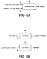
- FIG. 8A shows an embodiment of the present invention wherein the error is detected by comparing the loopback pattern to the calibration pattern.
- FIG. 8B shows an embodiment of the present invention wherein the error is detected by encoding the calibration pattern and detecting invalid data in the loopback pattern.
- FIG. 2A shows an embodiment of the present invention comprising a disk drive 12 for connecting to a host 14 , the host 14 comprising loopback circuitry 16 operable to loop a pattern received from the disk drive 12 back to the disk drive 12 .
- the disk drive 12 comprises a disk 3 , a head 5 actuated over the disk 3 , and interface circuitry 13 for interfacing with the host 14 .
- the interface circuitry 13 comprises a transmitter driver 18 operable to transmit transmission signals 20 at a transmission amplitude, and a receiver driver 22 operable to receive reception signals 24 .
- the disk drive 12 further comprises control circuitry 26 operable to calibrate the transmission amplitude.
- the control circuitry 26 executes the flow diagram of FIG.
- the transmitter driver 18 is configured (over line 19 ) to transmit at an initial transmission amplitude, and at step 30 a calibration pattern 32 is transmitted to the host 14 through the transmitter driver 18 .
- the reception signals 24 received by the receiver driver 22 are monitored to detect a loopback pattern 36 representing a loopback of the calibration pattern.
- the loopback pattern is processed to detect an error, and at step 40 the transmission amplitude is adjusted in response to the error.
- the disk drive 12 is a serial attached disk drive, such as a serial advanced technology attachment (SATA) disk drive, connected to a serial attached host 14 .
- SATA serial advanced technology attachment
- control circuitry 26 comprises a microprocessor executing instructions, the instructions being operable to cause the microprocessor to perform the steps of FIG. 2B as well as other functions described herein.
- the instructions may be stored in any computer-readable medium. In one embodiment, they may be stored on a non-volatile semiconductor memory external to the microprocessor, or integrated with the microprocessor in a system on a chip (SOC). In another embodiment, the instructions are stored on the disk 3 and read into a volatile semiconductor memory. In yet another embodiment, the control circuitry 26 comprises suitable logic circuitry, such as state machine circuitry.
- the calibration pattern 32 may also be generated using any suitable circuitry, and may be considered an integral part of the control circuitry 26 .
- a pattern generator 42 generates the calibration pattern 32 in any suitable manner, such as by using a sequence generator implemented with a suitable polynomial (e.g., a pseudo random number generator), or by reading the calibration pattern from a non-volatile memory.
- the calibration pattern 32 may comprise any suitable sequence, and in one embodiment, comprises a number of different sequences in order to calibrate the transmission amplitude over a desired bandwidth of the communication channel.
- the circuitry for detecting the error in the loopback pattern 36 may comprise any suitable circuitry, and may also be considered an integral part of the control circuitry 26 .
- an error detector 44 detects the error in the loopback pattern 36 and the control circuitry 26 responds to the error by adjusting the transmission amplitude of the transmitter driver 18 .
- the error detector 44 may detect the error in the loopback pattern 36 in any suitable manner, such as by comparing the calibration pattern 32 to the loopback pattern 36 , or by detecting invalid data when decoding the loopback pattern 36 .
- the transmission amplitude may be calibrated at any suitable time during communication between the disk drive 12 and the host 14 .
- the transmission amplitude is calibrated during a calibration interval of a communication reset procedure.
- the calibration interval occurs in response to the SATA disk drive receiving an out-of-band signal from the host.
- FIG. 3 shows the signaling sequence of the SATA interface during a reset procedure (e.g., during a power-on sequence).
- the host transmits a COMRESET signal to the disk drive, and the disk drive responds with a COMINIT signal.
- the host performs any suitable calibration procedures during a host calibration interval, and then sends a COMWAKE signal to the disk drive.
- the disk drive calibrates the transmission amplitude by executing the flow diagram of FIG. 2B .
- the disk drive transmits the calibration pattern at four progressively larger transmission amplitudes (a, b, c, d) wherein the corresponding loopback pattern is error free when transmitting at amplitude d.
- the disk drive saves transmission amplitude d as the operating transmission amplitude, and transmits a COMWAKE signal to the host which begins the normal communication process denoted as COMREADY.
- the transmission amplitude may be adjusted in any suitable manner in response to errors detected in the loopback pattern during the calibration process.
- FIG. 4 illustrates an embodiment wherein the transmission amplitude is increased until the loopback pattern is received error free.
- the transmission amplitude is initialized to a minimum value, and at step 48 the calibration pattern is transmitted to the host.
- the loopback pattern is received from the host, and at step 52 the loopback pattern is processed to detect an error. If an error is detected, the transmission amplitude is increased at step 54 , and if at step 56 the transmission amplitude has not reached a maximum, then the flow diagram of FIG. 4 is re-executed starting at step 48 . In this manner the transmission amplitude is increased until the loopback pattern is received error free at step 52 , or until the transmission amplitude reaches a maximum value.
- FIG. 5 shows an alternative embodiment of the present invention wherein the transmission amplitude is decreased until an error is detected in the loopback pattern.
- the transmission amplitude is initialized to a maximum value, and at step 60 the calibration pattern is transmitted to the host.
- the loopback pattern is received from the host, and at step 64 the loopback pattern is processed to detect an error. If an error is not detected, the transmission amplitude is decreased at step 66 , and the flow diagram of FIG. 5 is re-executed starting at step 60 . This process is repeated until the transmission amplitude reaches a minimum at step 68 .
- the transmission amplitude is decreased until an error is detected in the loopback pattern at step 64 , or until the transmission amplitude reaches a minimum value. If an error is detected in the loopback pattern at step 64 , then at step 70 the transmission amplitude is increased to revert the transmission amplitude to where the loopback pattern was received error free. This embodiment optimizes power consumption by transmitting at the lowest reliable transmission amplitude.
- FIG. 6 shows yet another embodiment of the present invention wherein the transmission amplitude is set to a plurality of different values and a plurality of corresponding error values are detected. An operating transmission amplitude is then selected in response to the plurality of error values.
- the transmission amplitude is initialized to a minimum value, and at step 74 the calibration pattern is transmitted to the host.
- the loopback pattern is received from the host, and at step 78 the loopback pattern is processed to detect an error.
- the transmission amplitude is increased and the flow diagram of FIG. 6 re-executed starting at step 74 until at step 82 the last transmission amplitude value has been tested.
- the operating transmission amplitude is selected in response to the plurality of error values detected at step 78 .
- the operating transmission amplitude is selected so as to minimize the number of errors detected in the loopback pattern, and in an alternative embodiment, the operating transmission amplitude is selected so that the number of errors detected in the loopback pattern falls below a predetermined threshold.
- the operating transmission amplitude is selected so that the number of errors detected in the loopback pattern falls below a predetermined threshold.
- FIG. 7 illustrates an embodiment of the present invention wherein at step 86 the control circuitry 26 of the disk drive 12 transmits a request to the host 14 to enable the loopback circuitry 16 .
- the control circuitry 26 transmits a frame information structure (FIS) to the host, including a built-in self test (BIST) FIS to enable the loopback circuitry 16 .
- FIS frame information structure
- BIST built-in self test
- the transmission amplitude is calibrated (e.g., by executing the flow diagram of FIG. 4 , 5 , or 6 ), and at step 90 the control circuitry 26 transmits a COMINIT signal to the host in order to exit the BIST sequence and resume normal operation.
- any suitable technique may be employed to detect an error in the loopback pattern 36 received from the host 14 .
- an error is detected by comparing the loopback pattern 36 to the calibration pattern 32 using comparator 92 .
- the pattern generator 42 FIG. 2A
- the pattern generator 42 comprises an encoder 94 for encoding an input pattern using any suitable code (e.g., a run-length limited code) to generate the calibration pattern 32 transmitted to the host.
- the error detector 44 ( FIG. 2A ) comprises a suitable decoder 96 for decoding the loopback pattern 36 received from the host 14 , wherein an error is detected if the decoder 96 detects invalid data in the loopback pattern 36 .
Abstract
Description
Claims (27)
Priority Applications (1)
| Application Number | Priority Date | Filing Date | Title |
|---|---|---|---|
| US11/280,046 US7280302B1 (en) | 2005-11-16 | 2005-11-16 | Disk drive using loopback to calibrate transmission amplitude |
Applications Claiming Priority (1)
| Application Number | Priority Date | Filing Date | Title |
|---|---|---|---|
| US11/280,046 US7280302B1 (en) | 2005-11-16 | 2005-11-16 | Disk drive using loopback to calibrate transmission amplitude |
Publications (1)
| Publication Number | Publication Date |
|---|---|
| US7280302B1 true US7280302B1 (en) | 2007-10-09 |
Family
ID=38562163
Family Applications (1)
| Application Number | Title | Priority Date | Filing Date |
|---|---|---|---|
| US11/280,046 Expired - Fee Related US7280302B1 (en) | 2005-11-16 | 2005-11-16 | Disk drive using loopback to calibrate transmission amplitude |
Country Status (1)
| Country | Link |
|---|---|
| US (1) | US7280302B1 (en) |
Cited By (129)
| Publication number | Priority date | Publication date | Assignee | Title |
|---|---|---|---|---|
| US20090024875A1 (en) * | 2007-07-20 | 2009-01-22 | Cheong Woo Seong | Serial advanced technology attachment device and method testing the same |
| US20090146721A1 (en) * | 2007-12-07 | 2009-06-11 | Renesas Technology Corp. | Oob (out of band) detection circuit and serial ata system |
| US20100218043A1 (en) * | 2009-02-26 | 2010-08-26 | Hon Hai Precision Industry Co., Ltd. | System and method for testing a serial attached small computer system interface |
| US20100217898A1 (en) * | 2009-02-24 | 2010-08-26 | Seagate Technology Llc | Receiver training during a sata out of band sequence |
| US20100251042A1 (en) * | 2009-03-30 | 2010-09-30 | Denali Software, Inc. | Double data rate memory physical interface high speed testing using self checking loopback |
| US8014977B1 (en) | 2005-03-28 | 2011-09-06 | Western Digital Technologies, Inc. | Serial interface amplitude selection for a disk drive in an unknown interconnect environment |
| US8879188B1 (en) | 2010-08-23 | 2014-11-04 | Western Digital Technologies, Inc. | Disk drive employing fly height calibration tracks to account for magnetic entropy and thermal decay |
| US8891193B1 (en) | 2013-05-09 | 2014-11-18 | Western Digital Technologies, Inc. | Disk drive calibrating threshold and gain of touchdown sensor |
| US8891341B1 (en) | 2013-03-11 | 2014-11-18 | Western Digital Technologies, Inc. | Energy assisted magnetic recording disk drive using modulated laser light |
| US8902527B1 (en) | 2010-03-22 | 2014-12-02 | Western Digital Technologies, Inc. | Systems and methods for improving sequential data rate performance using sorted data zones |
| US8902529B1 (en) | 2012-11-20 | 2014-12-02 | Western Digital Technologies, Inc. | Dual frequency crystal oscillator |
| US8908311B1 (en) | 2014-01-27 | 2014-12-09 | Western Digital Technologies, Inc. | Data storage device writing a multi-sector codeword in segments over multiple disk revolutions |
| US8909889B1 (en) | 2011-10-10 | 2014-12-09 | Western Digital Technologies, Inc. | Method and apparatus for servicing host commands by a disk drive |
| US8914625B1 (en) | 2009-07-31 | 2014-12-16 | Western Digital Technologies, Inc. | Automatically configuring a web browser file when booting an operating system from a data storage device |
| US8922939B1 (en) | 2013-04-02 | 2014-12-30 | Western Digital Technologies, Inc. | Disk drive generating feed-forward fly height control based on temperature sensitive fly height sensor |
| US8937782B1 (en) | 2012-05-07 | 2015-01-20 | Western Digital Technologies, Inc. | Hard disk drive assembly including a NVSM to store configuration data for controlling disk drive operations |
| US8941941B1 (en) | 2013-02-28 | 2015-01-27 | Western Digital Technologies, Inc. | Disk drive calibrating touchdown sensor |
| US8949521B1 (en) | 2013-04-10 | 2015-02-03 | Western Digital Technologies, Inc. | Actuator prepositioning for disk drive |
| US8947812B1 (en) | 2014-03-27 | 2015-02-03 | Western Digital Technologies, Inc. | Data storage device comprising equalizer filter and inter-track interference filter |
| US8953269B1 (en) | 2014-07-18 | 2015-02-10 | Western Digital Technologies, Inc. | Management of data objects in a data object zone |
| US8954664B1 (en) | 2010-10-01 | 2015-02-10 | Western Digital Technologies, Inc. | Writing metadata files on a disk |
| US8953277B1 (en) | 2014-06-16 | 2015-02-10 | Western Digital Technologies, Inc. | Data storage device writing tracks on a disk with equal spacing |
| US8958167B1 (en) | 2013-12-23 | 2015-02-17 | Western Digital Technologies, Inc. | Detection of disk surface irregularities in data storage devices |
| US8959281B1 (en) | 2012-11-09 | 2015-02-17 | Western Digital Technologies, Inc. | Data management for a storage device |
| US8970978B1 (en) | 2012-10-22 | 2015-03-03 | Western Digital Technologies, Inc. | Disk drive detecting head touchdown by applying DC+AC control signal to fly height actuator |
| US8976633B1 (en) | 2014-04-15 | 2015-03-10 | Western Digital Technologies, Inc. | Data storage device calibrating fly height actuator based on laser power for heat assisted magnetic recording |
| US8988809B1 (en) | 2014-02-18 | 2015-03-24 | Western Digital (Fremont), Llc | Disk recording device for writing a radially coherent reference band by measuring relative timing offsets of reference bursts |
| US8990493B1 (en) | 2011-06-30 | 2015-03-24 | Western Digital Technologies, Inc. | Method and apparatus for performing force unit access writes on a disk |
| US8988810B1 (en) | 2014-04-16 | 2015-03-24 | Western Digital Technologies, Inc. | Track measurement for data storage device |
| US8996839B1 (en) | 2012-01-23 | 2015-03-31 | Western Digital Technologies, Inc. | Data storage device aligning partition to boundary of sector when partition offset correlates with offset of write commands |
| US9001453B1 (en) | 2014-07-18 | 2015-04-07 | Western Digital Technologies, Inc. | Data storage device calibrating fly height actuator based on read mode touchdown resistance of touchdown sensor |
| US9009358B1 (en) | 2008-09-23 | 2015-04-14 | Western Digital Technologies, Inc. | Configuring a data storage device with a parameter file interlocked with configuration code |
| US9013818B1 (en) | 2013-12-06 | 2015-04-21 | Western Digital Technologies, Inc. | Disk drive measuring reader/writer gap by measuring fractional clock cycle over disk radius |
| US9013821B1 (en) | 2014-06-10 | 2015-04-21 | Western Digital Technologies, Inc. | Data storage device employing one-dimensional and two-dimensional channels |
| US9021410B1 (en) | 2013-12-10 | 2015-04-28 | Western Technologies, Inc. | Electronic system with multi-cycle simulation coverage mechanism and method of operation thereof |
| US9025421B1 (en) | 2014-10-08 | 2015-05-05 | Western Digital Technologies, Inc. | Data storage device adjusting laser input power to compensate for temperature variations |
| US9025270B1 (en) | 2013-09-17 | 2015-05-05 | Western Digital Technologies, Inc. | Electronic system with current conservation mechanism and method of operation thereof |
| US9025267B1 (en) | 2014-06-09 | 2015-05-05 | Western Digital Technologies, Inc. | Data storage device using branch metric from adjacent track to compensate for inter-track interference |
| US9047917B1 (en) | 2013-11-26 | 2015-06-02 | Western Digital Technologies, Inc. | Disk drive slider with sense amplifier for coupling to a preamp through a supply/bias line and a read signal line |
| US9049471B2 (en) | 2001-10-17 | 2015-06-02 | Keen Personal Media, Inc. | Personal video recorder for inserting a stored advertisement into a displayed broadcast stream |
| US9053730B1 (en) | 2012-05-11 | 2015-06-09 | Western Digital Technologies, Inc. | Disk drive comprising extended range head proximity sensor |
| US9053749B1 (en) | 2013-03-15 | 2015-06-09 | Western Digital Technologies, Inc. | Disk drive comprising a per-drive and per-head fly height filter |
| US9060420B2 (en) | 2007-11-01 | 2015-06-16 | Western Digitial Technologies, Inc. | Method of manufacturing a double sided flex circuit for a disk drive wherein a first side lead provides an etching mask for a second side lead |
| US9063838B1 (en) | 2012-01-23 | 2015-06-23 | Western Digital Technologies, Inc. | Data storage device shifting data chunks of alignment zone relative to sector boundaries |
| US9064542B1 (en) | 2013-04-08 | 2015-06-23 | Western Digital Technologies, Inc. | Scheduled load of heads to reduce lubricant migration on pole tip and decrease time to ready |
| US9064504B1 (en) | 2014-01-29 | 2015-06-23 | Western Digital Technologies, Inc. | Electronic system with media recovery mechanism and method of operation thereof |
| US9064525B2 (en) | 2013-11-26 | 2015-06-23 | Western Digital Technologies, Inc. | Disk drive comprising laser transmission line optimized for heat assisted magnetic recording |
| US9070406B1 (en) | 2014-03-10 | 2015-06-30 | Western Digital Technologies, Inc. | Disk drive configuring one-dimensional and two-dimensional recording areas based on read element spacing |
| US9075714B1 (en) | 2014-05-13 | 2015-07-07 | Western Digital Technologies, Inc. | Electronic system with data management mechanism and method of operation thereof |
| US9074941B1 (en) | 2013-03-14 | 2015-07-07 | Western Digital Technologies, Inc. | Systems and methods for measuring ambient and laser temperature in heat assisted magnetic recording |
| US9076474B1 (en) | 2014-12-23 | 2015-07-07 | Western Digital Technologies, Inc. | Data storage device attenuating thermal decay effect on fly height measurement |
| US9082458B1 (en) | 2014-03-10 | 2015-07-14 | Western Digital Technologies, Inc. | Data storage device balancing and maximizing quality metric when configuring arial density of each disk surface |
| US9099134B1 (en) | 2015-01-27 | 2015-08-04 | Western Digital Technologies, Inc. | Data storage device employing multiple jog profiles for a butterfly written disk surface |
| US9099103B1 (en) | 2014-10-21 | 2015-08-04 | Western Digital Technologies, Inc. | Heat assisted magnetic recording withinterlaced high-power heated and low-power heated tracks |
| US9099144B1 (en) | 2013-10-11 | 2015-08-04 | Western Digital Technologies, Inc. | Disk drive evaluating laser performance for heat assisted magnetic recording |
| US9117463B1 (en) | 2014-06-23 | 2015-08-25 | Western Digital Technologies, Inc. | Data storage device erasing multiple adjacent data tracks to recover from inter-track interference |
| US9117479B1 (en) | 2014-09-24 | 2015-08-25 | Western Digital Technologies, Inc. | Data storage device calibrating laser write power for heat assisted magnetic recording |
| US9117489B1 (en) | 2014-02-18 | 2015-08-25 | Western Digital Technologies, Inc. | Data storage device screening heads by verifying defects after defect scan |
| US9123382B1 (en) | 2014-10-28 | 2015-09-01 | Western Digital Technologies, Inc. | Non-volatile caching for sequence of data |
| US9123370B1 (en) | 2014-04-15 | 2015-09-01 | Western Digital Technologies, Inc. | Data storage device calibrating fly height actuator based on laser power for heat assisted magnetic recording |
| US9129628B1 (en) | 2014-10-23 | 2015-09-08 | Western Digital Technologies, Inc. | Data management for data storage device with different track density regions |
| US9128820B1 (en) | 2012-06-18 | 2015-09-08 | Western Digital Technologies, Inc. | File management among different zones of storage media |
| US9135205B1 (en) | 2013-05-01 | 2015-09-15 | Western Digital Technologies, Inc. | Data storage assembly for archive cold storage |
| US9153266B1 (en) | 2014-09-11 | 2015-10-06 | Western Digital Technologies, Inc. | Data storage device measuring laser protrusion fly height profile |
| US9153287B1 (en) | 2013-05-13 | 2015-10-06 | Western Digital Technologies, Inc. | Data access for shingled magnetic recording media |
| US9158722B1 (en) | 2011-11-02 | 2015-10-13 | Western Digital Technologies, Inc. | Data storage device to communicate with a host in a SATA or a USB mode |
| US9164694B1 (en) | 2013-06-19 | 2015-10-20 | Western Digital Technologies, Inc. | Data storage device detecting read-before-write conditions and returning configurable return data |
| US9171575B1 (en) | 2014-06-23 | 2015-10-27 | Western Digital Technologies, Inc. | Data storage device detecting media defects by writing opposite polarity test pattern |
| US9183864B1 (en) | 2013-06-13 | 2015-11-10 | Western Digital Technologies, Inc. | Disk drive adjusting closed-loop fly height target based on change in open-loop fly height control signal |
| US9183877B1 (en) | 2015-03-20 | 2015-11-10 | Western Digital Technologies, Inc. | Data storage device comprising two-dimensional data dependent noise whitening filters for two-dimensional recording |
| US9189392B1 (en) | 2011-06-30 | 2015-11-17 | Western Digital Technologies, Inc. | Opportunistic defragmentation during garbage collection |
| US9196302B1 (en) | 2015-03-18 | 2015-11-24 | Western Digital Technologies, Inc. | Electronic system with media maintenance mechanism and method of operation thereof |
| US9213493B1 (en) | 2011-12-16 | 2015-12-15 | Western Digital Technologies, Inc. | Sorted serpentine mapping for storage drives |
| US9214186B1 (en) | 2015-03-23 | 2015-12-15 | Western Digital Technologies, Inc. | Data storage device measuring radial offset between read element and write element |
| US9230585B1 (en) | 2014-01-31 | 2016-01-05 | Western Digital Technologies, Inc. | Per wedge preheat DFH to improve data storage device performance |
| US9230605B1 (en) | 2014-12-01 | 2016-01-05 | Western Digital Technologies, Inc. | Data storage device maximizing areal density based on a target quality metric |
| US9236086B1 (en) | 2014-10-15 | 2016-01-12 | Western Digital Technologies, Inc. | Methods for reducing operational latency of data storage systems |
| US9245558B1 (en) | 2014-05-09 | 2016-01-26 | Western Digital Technologies, Inc. | Electronic system with data management mechanism and method of operation thereof |
| US9245556B2 (en) | 2014-03-10 | 2016-01-26 | Western Digital Technologies, Inc. | Disk drive employing multiple read elements to increase radial band for two-dimensional magnetic recording |
| US9251856B1 (en) | 2014-05-30 | 2016-02-02 | Western Digial Technologies, Inc. | Read failover method and apparatus for a data storage system |
| US9251844B1 (en) | 2014-06-02 | 2016-02-02 | Western Digital Technologies, Inc. | Waterfall method and apparatus for a data storage device read system |
| US9257146B1 (en) | 2014-02-11 | 2016-02-09 | Western Digital Technologies, Inc. | Data storage device comprising sequence detector compensating for inter-track interference |
| US9257143B1 (en) | 2014-12-23 | 2016-02-09 | Western Digital Technologies, Inc. | Precautionary measures for data storage device environmental conditions |
| US9257145B1 (en) | 2013-11-27 | 2016-02-09 | Western Digital Technologies, Inc. | Disk drive measuring down-track spacing of read sensors |
| US9263088B2 (en) | 2014-03-21 | 2016-02-16 | Western Digital Technologies, Inc. | Data management for a data storage device using a last resort zone |
| US9268499B1 (en) | 2010-08-13 | 2016-02-23 | Western Digital Technologies, Inc. | Hybrid drive migrating high workload data from disk to non-volatile semiconductor memory |
| US9268649B1 (en) | 2011-06-23 | 2016-02-23 | Western Digital Technologies, Inc. | Disk drive with recent write streams list for data refresh determination |
| US9269393B1 (en) | 2014-12-08 | 2016-02-23 | Western Digital Technologies, Inc. | Electronic system with data refresh mechanism and method of operation thereof |
| US9281009B1 (en) | 2014-12-18 | 2016-03-08 | Western Digital Technologies, Inc. | Data storage device employing variable size interleave written track segments |
| US9311939B1 (en) | 2014-12-23 | 2016-04-12 | Western Digital Technologies, Inc. | Write-through media caching |
| US9318137B1 (en) | 2015-03-13 | 2016-04-19 | Western Digital Technologies, Inc. | Data storage device executing retry operation by buffering signal samples at different radial offsets |
| US9330715B1 (en) | 2010-03-22 | 2016-05-03 | Western Digital Technologies, Inc. | Mapping of shingled magnetic recording media |
| US9355666B1 (en) | 2013-09-30 | 2016-05-31 | Western Digital Technologies, Inc. | Disk drive measuring stroke difference between heads by detecting a difference between ramp contact |
| US9361938B1 (en) | 2015-04-16 | 2016-06-07 | Western Digital Technologies, Inc. | Disk defect management for a data storage device |
| US9368131B1 (en) | 2015-04-03 | 2016-06-14 | Western Digital (Fremont), Llc | Data storage device employing mirrored cross-track profiles for top and bottom disk surfaces |
| US9368132B1 (en) | 2015-09-04 | 2016-06-14 | Western Digital Technologies, Inc. | Data storage device employing differential write data signal and differential write pattern signal |
| US9383923B1 (en) | 2012-10-18 | 2016-07-05 | Western Digital Technologies, Inc. | Write pointer management for a disk drive |
| US9401165B1 (en) | 2014-05-05 | 2016-07-26 | Western Digital Technologies, Inc. | Method and system to monitor magnetic head loading and unloading stability for a data storage system |
| US9417628B2 (en) | 2013-03-13 | 2016-08-16 | Western Digital Technologies, Inc. | Production failure analysis system |
| US9424864B2 (en) | 2014-07-02 | 2016-08-23 | Western Digital Technologies, Inc. | Data management for a data storage device with zone relocation |
| US9437242B1 (en) | 2015-09-14 | 2016-09-06 | Western Digital Technologies, Inc. | Data storage device employing different frequency preambles in adjacent data tracks |
| US9466318B2 (en) | 2014-12-24 | 2016-10-11 | Western Digital Technologies, Inc. | Allowing fast data zone switches on data storage devices |
| US9466321B1 (en) | 2015-06-05 | 2016-10-11 | Western Digital Technologies, Inc. | Angular position tracking of data accesses to mitigate risk of data loss |
| US9472219B1 (en) | 2015-05-01 | 2016-10-18 | Western Digital Technologies, Inc. | Data storage device calibrating parameter for heat assisted magnetic recording |
| US9501393B2 (en) | 2014-01-27 | 2016-11-22 | Western Digital Technologies, Inc. | Data storage system garbage collection based on at least one attribute |
| US9502068B1 (en) | 2015-04-08 | 2016-11-22 | Western Digital Technologies, Inc. | Data storage device updating laser power during non-write mode for heat assisted magnetic recording |
| US9588898B1 (en) | 2015-06-02 | 2017-03-07 | Western Digital Technologies, Inc. | Fullness control for media-based cache operating in a steady state |
| US9600205B1 (en) | 2014-09-22 | 2017-03-21 | Western Digital Technologies, Inc. | Power aware power safe write buffer |
| US9632711B1 (en) | 2014-04-07 | 2017-04-25 | Western Digital Technologies, Inc. | Processing flush requests by utilizing storage system write notifications |
| US9639287B1 (en) | 2015-06-29 | 2017-05-02 | Western Digital Technologies, Inc. | Write command reporting |
| US9645752B1 (en) | 2014-04-07 | 2017-05-09 | Western Digital Technologies, Inc. | Identification of data committed to non-volatile memory by use of notification commands |
| US9672107B1 (en) | 2015-02-11 | 2017-06-06 | Western Digital Technologies, Inc. | Data protection for a data storage device |
| US20170160929A1 (en) * | 2015-12-02 | 2017-06-08 | Hewlett Packard Enterprise Development Lp | In-order execution of commands received via a networking fabric |
| US9747928B1 (en) | 2014-09-25 | 2017-08-29 | Western Digital Technologies, Inc. | Data storage device modifying write operation when a laser mode hop is detected |
| US9761273B1 (en) | 2015-11-03 | 2017-09-12 | Western Digital Technologies, Inc. | Data storage device encoding and interleaving codewords to improve trellis sequence detection |
| US9842617B1 (en) | 2015-06-29 | 2017-12-12 | Western Digital Technologies, Inc. | Electronic system with head management mechanism and method of operation thereof |
| US9842622B1 (en) | 2014-12-23 | 2017-12-12 | Western Digital Technologies, Inc. | Data storage device having improved read failure tolerance |
| US9864529B1 (en) | 2014-01-27 | 2018-01-09 | Western Digital Technologies, Inc. | Host compatibility for host managed storage media |
| US9870281B1 (en) | 2015-03-20 | 2018-01-16 | Western Digital Technologies, Inc. | Power loss mitigation for data storage device |
| US9875055B1 (en) | 2014-08-04 | 2018-01-23 | Western Digital Technologies, Inc. | Check-pointing of metadata |
| US9916616B2 (en) | 2014-03-31 | 2018-03-13 | Western Digital Technologies, Inc. | Inventory management system using incremental capacity formats |
| US9933955B1 (en) | 2015-03-05 | 2018-04-03 | Western Digital Technologies, Inc. | Power safe write buffer for data storage device |
| US9952950B1 (en) | 2014-09-08 | 2018-04-24 | Western Digital Technologies, Inc. | Data management in RAID environment |
| US9959052B1 (en) | 2015-09-17 | 2018-05-01 | Western Digital Technologies, Inc. | Media based cache for data storage device |
| US10056920B1 (en) | 2015-11-03 | 2018-08-21 | Western Digital Technologies, Inc. | Data storage device encoding and interleaving codewords to improve trellis sequence detection |
| US10063257B1 (en) | 2015-11-03 | 2018-08-28 | Western Digital Technologies, Inc. | Data storage device encoding and interleaving codewords to improve trellis sequence detection |
| US10282096B1 (en) | 2014-12-17 | 2019-05-07 | Western Digital Technologies, Inc. | Identification of data with predetermined data pattern |
| US10282371B1 (en) | 2014-12-02 | 2019-05-07 | Western Digital Technologies, Inc. | Object storage device with probabilistic data structure |
| US10365836B1 (en) | 2015-01-27 | 2019-07-30 | Western Digital Technologies, Inc. | Electronic system with declustered data protection by parity based on reliability and method of operation thereof |
Citations (5)
| Publication number | Priority date | Publication date | Assignee | Title |
|---|---|---|---|---|
| US5128962A (en) | 1989-06-16 | 1992-07-07 | Texas Instruments Incorporated | Line interface circuit and a method of testing such a circuit |
| US6052655A (en) * | 1997-03-19 | 2000-04-18 | Hitachi, Ltd. | System for converting input/output signals where each amplifier section comprises a storage unit containing information items relating to an associated terminal end |
| US6069494A (en) | 1996-10-18 | 2000-05-30 | Nec Corporation | Method and apparatus for interfacing semiconductor devices for transfer therebetween having a serial bus for transmitting amplitude data from a master device to a slave device |
| US20050024083A1 (en) | 2003-07-31 | 2005-02-03 | Kabushiki Kaisha Toshiba | Electronic device with serial ATA interface and signal amplitude automatic adjustment method |
| US7027245B2 (en) * | 2004-04-30 | 2006-04-11 | Hitachi Global Storage Technologies Netherlands B.V. | Apparatus for providing head amplitude characterization using gain loops |
-
2005
- 2005-11-16 US US11/280,046 patent/US7280302B1/en not_active Expired - Fee Related
Patent Citations (5)
| Publication number | Priority date | Publication date | Assignee | Title |
|---|---|---|---|---|
| US5128962A (en) | 1989-06-16 | 1992-07-07 | Texas Instruments Incorporated | Line interface circuit and a method of testing such a circuit |
| US6069494A (en) | 1996-10-18 | 2000-05-30 | Nec Corporation | Method and apparatus for interfacing semiconductor devices for transfer therebetween having a serial bus for transmitting amplitude data from a master device to a slave device |
| US6052655A (en) * | 1997-03-19 | 2000-04-18 | Hitachi, Ltd. | System for converting input/output signals where each amplifier section comprises a storage unit containing information items relating to an associated terminal end |
| US20050024083A1 (en) | 2003-07-31 | 2005-02-03 | Kabushiki Kaisha Toshiba | Electronic device with serial ATA interface and signal amplitude automatic adjustment method |
| US7027245B2 (en) * | 2004-04-30 | 2006-04-11 | Hitachi Global Storage Technologies Netherlands B.V. | Apparatus for providing head amplitude characterization using gain loops |
Non-Patent Citations (2)
| Title |
|---|
| "Serial ATA: High Speed Serialized AT Attachment", http://www.serialata.org, Jan. 7, 2003, Revision 1.0a, pp. 106-111. |
| U.S. Appl. No. 11/092,119, Masiewicz et al. |
Cited By (145)
| Publication number | Priority date | Publication date | Assignee | Title |
|---|---|---|---|---|
| US9049471B2 (en) | 2001-10-17 | 2015-06-02 | Keen Personal Media, Inc. | Personal video recorder for inserting a stored advertisement into a displayed broadcast stream |
| US8014977B1 (en) | 2005-03-28 | 2011-09-06 | Western Digital Technologies, Inc. | Serial interface amplitude selection for a disk drive in an unknown interconnect environment |
| US8145452B1 (en) | 2005-03-28 | 2012-03-27 | Western Digital Technologies, Inc. | Serial interface amplitude selection for a disk drive in an unknown interconnect environment |
| US20090024875A1 (en) * | 2007-07-20 | 2009-01-22 | Cheong Woo Seong | Serial advanced technology attachment device and method testing the same |
| US9060420B2 (en) | 2007-11-01 | 2015-06-16 | Western Digitial Technologies, Inc. | Method of manufacturing a double sided flex circuit for a disk drive wherein a first side lead provides an etching mask for a second side lead |
| KR101536359B1 (en) * | 2007-12-07 | 2015-07-13 | 르네사스 일렉트로닉스 가부시키가이샤 | Oob detection circuit and serial ata system |
| US20090146721A1 (en) * | 2007-12-07 | 2009-06-11 | Renesas Technology Corp. | Oob (out of band) detection circuit and serial ata system |
| US8199858B2 (en) * | 2007-12-07 | 2012-06-12 | Renesas Electronics Corporation | OOB (out of band) detection circuit and serial ATA system |
| US9009358B1 (en) | 2008-09-23 | 2015-04-14 | Western Digital Technologies, Inc. | Configuring a data storage device with a parameter file interlocked with configuration code |
| US9753887B2 (en) | 2009-02-24 | 2017-09-05 | Seagate Technology Llc | Receiver training during a SATA out of band sequence |
| US20100217898A1 (en) * | 2009-02-24 | 2010-08-26 | Seagate Technology Llc | Receiver training during a sata out of band sequence |
| US20180129627A1 (en) * | 2009-02-24 | 2018-05-10 | Seagate Technology, Llc | Receiver training during a sata out of band sequence |
| US7971110B2 (en) * | 2009-02-26 | 2011-06-28 | Hon Hai Precision Industry Co., Ltd. | System and method for testing a serial attached small computer system interface |
| US20100218043A1 (en) * | 2009-02-26 | 2010-08-26 | Hon Hai Precision Industry Co., Ltd. | System and method for testing a serial attached small computer system interface |
| US20100251042A1 (en) * | 2009-03-30 | 2010-09-30 | Denali Software, Inc. | Double data rate memory physical interface high speed testing using self checking loopback |
| US9043662B2 (en) * | 2009-03-30 | 2015-05-26 | Cadence Design Systems, Inc. | Double data rate memory physical interface high speed testing using self checking loopback |
| US8914625B1 (en) | 2009-07-31 | 2014-12-16 | Western Digital Technologies, Inc. | Automatically configuring a web browser file when booting an operating system from a data storage device |
| US8902527B1 (en) | 2010-03-22 | 2014-12-02 | Western Digital Technologies, Inc. | Systems and methods for improving sequential data rate performance using sorted data zones |
| US9330715B1 (en) | 2010-03-22 | 2016-05-03 | Western Digital Technologies, Inc. | Mapping of shingled magnetic recording media |
| US9268499B1 (en) | 2010-08-13 | 2016-02-23 | Western Digital Technologies, Inc. | Hybrid drive migrating high workload data from disk to non-volatile semiconductor memory |
| US8879188B1 (en) | 2010-08-23 | 2014-11-04 | Western Digital Technologies, Inc. | Disk drive employing fly height calibration tracks to account for magnetic entropy and thermal decay |
| US8954664B1 (en) | 2010-10-01 | 2015-02-10 | Western Digital Technologies, Inc. | Writing metadata files on a disk |
| US9268649B1 (en) | 2011-06-23 | 2016-02-23 | Western Digital Technologies, Inc. | Disk drive with recent write streams list for data refresh determination |
| US9189392B1 (en) | 2011-06-30 | 2015-11-17 | Western Digital Technologies, Inc. | Opportunistic defragmentation during garbage collection |
| US8990493B1 (en) | 2011-06-30 | 2015-03-24 | Western Digital Technologies, Inc. | Method and apparatus for performing force unit access writes on a disk |
| US8909889B1 (en) | 2011-10-10 | 2014-12-09 | Western Digital Technologies, Inc. | Method and apparatus for servicing host commands by a disk drive |
| US9158722B1 (en) | 2011-11-02 | 2015-10-13 | Western Digital Technologies, Inc. | Data storage device to communicate with a host in a SATA or a USB mode |
| US9213493B1 (en) | 2011-12-16 | 2015-12-15 | Western Digital Technologies, Inc. | Sorted serpentine mapping for storage drives |
| US9063838B1 (en) | 2012-01-23 | 2015-06-23 | Western Digital Technologies, Inc. | Data storage device shifting data chunks of alignment zone relative to sector boundaries |
| US8996839B1 (en) | 2012-01-23 | 2015-03-31 | Western Digital Technologies, Inc. | Data storage device aligning partition to boundary of sector when partition offset correlates with offset of write commands |
| US8937782B1 (en) | 2012-05-07 | 2015-01-20 | Western Digital Technologies, Inc. | Hard disk drive assembly including a NVSM to store configuration data for controlling disk drive operations |
| US9053730B1 (en) | 2012-05-11 | 2015-06-09 | Western Digital Technologies, Inc. | Disk drive comprising extended range head proximity sensor |
| US9477681B2 (en) | 2012-06-18 | 2016-10-25 | Western Digital Technologies, Inc. | File management among different zones of storage media |
| US9128820B1 (en) | 2012-06-18 | 2015-09-08 | Western Digital Technologies, Inc. | File management among different zones of storage media |
| US9383923B1 (en) | 2012-10-18 | 2016-07-05 | Western Digital Technologies, Inc. | Write pointer management for a disk drive |
| US8970978B1 (en) | 2012-10-22 | 2015-03-03 | Western Digital Technologies, Inc. | Disk drive detecting head touchdown by applying DC+AC control signal to fly height actuator |
| US8959281B1 (en) | 2012-11-09 | 2015-02-17 | Western Digital Technologies, Inc. | Data management for a storage device |
| US8902529B1 (en) | 2012-11-20 | 2014-12-02 | Western Digital Technologies, Inc. | Dual frequency crystal oscillator |
| US8941941B1 (en) | 2013-02-28 | 2015-01-27 | Western Digital Technologies, Inc. | Disk drive calibrating touchdown sensor |
| US8891341B1 (en) | 2013-03-11 | 2014-11-18 | Western Digital Technologies, Inc. | Energy assisted magnetic recording disk drive using modulated laser light |
| US9417628B2 (en) | 2013-03-13 | 2016-08-16 | Western Digital Technologies, Inc. | Production failure analysis system |
| US9074941B1 (en) | 2013-03-14 | 2015-07-07 | Western Digital Technologies, Inc. | Systems and methods for measuring ambient and laser temperature in heat assisted magnetic recording |
| US9053749B1 (en) | 2013-03-15 | 2015-06-09 | Western Digital Technologies, Inc. | Disk drive comprising a per-drive and per-head fly height filter |
| US8922939B1 (en) | 2013-04-02 | 2014-12-30 | Western Digital Technologies, Inc. | Disk drive generating feed-forward fly height control based on temperature sensitive fly height sensor |
| US9064542B1 (en) | 2013-04-08 | 2015-06-23 | Western Digital Technologies, Inc. | Scheduled load of heads to reduce lubricant migration on pole tip and decrease time to ready |
| US8949521B1 (en) | 2013-04-10 | 2015-02-03 | Western Digital Technologies, Inc. | Actuator prepositioning for disk drive |
| US9135205B1 (en) | 2013-05-01 | 2015-09-15 | Western Digital Technologies, Inc. | Data storage assembly for archive cold storage |
| US8891193B1 (en) | 2013-05-09 | 2014-11-18 | Western Digital Technologies, Inc. | Disk drive calibrating threshold and gain of touchdown sensor |
| US9153287B1 (en) | 2013-05-13 | 2015-10-06 | Western Digital Technologies, Inc. | Data access for shingled magnetic recording media |
| US9183864B1 (en) | 2013-06-13 | 2015-11-10 | Western Digital Technologies, Inc. | Disk drive adjusting closed-loop fly height target based on change in open-loop fly height control signal |
| US9164694B1 (en) | 2013-06-19 | 2015-10-20 | Western Digital Technologies, Inc. | Data storage device detecting read-before-write conditions and returning configurable return data |
| US9025270B1 (en) | 2013-09-17 | 2015-05-05 | Western Digital Technologies, Inc. | Electronic system with current conservation mechanism and method of operation thereof |
| US9355666B1 (en) | 2013-09-30 | 2016-05-31 | Western Digital Technologies, Inc. | Disk drive measuring stroke difference between heads by detecting a difference between ramp contact |
| US9099144B1 (en) | 2013-10-11 | 2015-08-04 | Western Digital Technologies, Inc. | Disk drive evaluating laser performance for heat assisted magnetic recording |
| US9047917B1 (en) | 2013-11-26 | 2015-06-02 | Western Digital Technologies, Inc. | Disk drive slider with sense amplifier for coupling to a preamp through a supply/bias line and a read signal line |
| US9064525B2 (en) | 2013-11-26 | 2015-06-23 | Western Digital Technologies, Inc. | Disk drive comprising laser transmission line optimized for heat assisted magnetic recording |
| US9299371B1 (en) | 2013-11-26 | 2016-03-29 | Western Digital Technologies, Inc. | Disk drive slider with sense amplifier for coupling to a preamp through a supply/bias line and a read signal line |
| US9257145B1 (en) | 2013-11-27 | 2016-02-09 | Western Digital Technologies, Inc. | Disk drive measuring down-track spacing of read sensors |
| US9013818B1 (en) | 2013-12-06 | 2015-04-21 | Western Digital Technologies, Inc. | Disk drive measuring reader/writer gap by measuring fractional clock cycle over disk radius |
| US9021410B1 (en) | 2013-12-10 | 2015-04-28 | Western Technologies, Inc. | Electronic system with multi-cycle simulation coverage mechanism and method of operation thereof |
| US8958167B1 (en) | 2013-12-23 | 2015-02-17 | Western Digital Technologies, Inc. | Detection of disk surface irregularities in data storage devices |
| US10282130B2 (en) | 2014-01-27 | 2019-05-07 | Western Digital Technologies, Inc. | Coherency of data in data relocation |
| US9501393B2 (en) | 2014-01-27 | 2016-11-22 | Western Digital Technologies, Inc. | Data storage system garbage collection based on at least one attribute |
| US8908311B1 (en) | 2014-01-27 | 2014-12-09 | Western Digital Technologies, Inc. | Data storage device writing a multi-sector codeword in segments over multiple disk revolutions |
| US9864529B1 (en) | 2014-01-27 | 2018-01-09 | Western Digital Technologies, Inc. | Host compatibility for host managed storage media |
| US9064504B1 (en) | 2014-01-29 | 2015-06-23 | Western Digital Technologies, Inc. | Electronic system with media recovery mechanism and method of operation thereof |
| US9230585B1 (en) | 2014-01-31 | 2016-01-05 | Western Digital Technologies, Inc. | Per wedge preheat DFH to improve data storage device performance |
| US9257146B1 (en) | 2014-02-11 | 2016-02-09 | Western Digital Technologies, Inc. | Data storage device comprising sequence detector compensating for inter-track interference |
| US9117489B1 (en) | 2014-02-18 | 2015-08-25 | Western Digital Technologies, Inc. | Data storage device screening heads by verifying defects after defect scan |
| US8988809B1 (en) | 2014-02-18 | 2015-03-24 | Western Digital (Fremont), Llc | Disk recording device for writing a radially coherent reference band by measuring relative timing offsets of reference bursts |
| US9082458B1 (en) | 2014-03-10 | 2015-07-14 | Western Digital Technologies, Inc. | Data storage device balancing and maximizing quality metric when configuring arial density of each disk surface |
| US9070406B1 (en) | 2014-03-10 | 2015-06-30 | Western Digital Technologies, Inc. | Disk drive configuring one-dimensional and two-dimensional recording areas based on read element spacing |
| US9245556B2 (en) | 2014-03-10 | 2016-01-26 | Western Digital Technologies, Inc. | Disk drive employing multiple read elements to increase radial band for two-dimensional magnetic recording |
| US9263088B2 (en) | 2014-03-21 | 2016-02-16 | Western Digital Technologies, Inc. | Data management for a data storage device using a last resort zone |
| US8947812B1 (en) | 2014-03-27 | 2015-02-03 | Western Digital Technologies, Inc. | Data storage device comprising equalizer filter and inter-track interference filter |
| US9916616B2 (en) | 2014-03-31 | 2018-03-13 | Western Digital Technologies, Inc. | Inventory management system using incremental capacity formats |
| US9632711B1 (en) | 2014-04-07 | 2017-04-25 | Western Digital Technologies, Inc. | Processing flush requests by utilizing storage system write notifications |
| US10162534B1 (en) | 2014-04-07 | 2018-12-25 | Western Digital Technologies, Inc. | Ordering commitment of data from a data cache to nonvolatile memory using ordering commands |
| US9645752B1 (en) | 2014-04-07 | 2017-05-09 | Western Digital Technologies, Inc. | Identification of data committed to non-volatile memory by use of notification commands |
| US8976633B1 (en) | 2014-04-15 | 2015-03-10 | Western Digital Technologies, Inc. | Data storage device calibrating fly height actuator based on laser power for heat assisted magnetic recording |
| US9123370B1 (en) | 2014-04-15 | 2015-09-01 | Western Digital Technologies, Inc. | Data storage device calibrating fly height actuator based on laser power for heat assisted magnetic recording |
| US8988810B1 (en) | 2014-04-16 | 2015-03-24 | Western Digital Technologies, Inc. | Track measurement for data storage device |
| US9401165B1 (en) | 2014-05-05 | 2016-07-26 | Western Digital Technologies, Inc. | Method and system to monitor magnetic head loading and unloading stability for a data storage system |
| US9245558B1 (en) | 2014-05-09 | 2016-01-26 | Western Digital Technologies, Inc. | Electronic system with data management mechanism and method of operation thereof |
| US9075714B1 (en) | 2014-05-13 | 2015-07-07 | Western Digital Technologies, Inc. | Electronic system with data management mechanism and method of operation thereof |
| US9251856B1 (en) | 2014-05-30 | 2016-02-02 | Western Digial Technologies, Inc. | Read failover method and apparatus for a data storage system |
| US9251844B1 (en) | 2014-06-02 | 2016-02-02 | Western Digital Technologies, Inc. | Waterfall method and apparatus for a data storage device read system |
| US9025267B1 (en) | 2014-06-09 | 2015-05-05 | Western Digital Technologies, Inc. | Data storage device using branch metric from adjacent track to compensate for inter-track interference |
| US9013821B1 (en) | 2014-06-10 | 2015-04-21 | Western Digital Technologies, Inc. | Data storage device employing one-dimensional and two-dimensional channels |
| US8953277B1 (en) | 2014-06-16 | 2015-02-10 | Western Digital Technologies, Inc. | Data storage device writing tracks on a disk with equal spacing |
| US9171575B1 (en) | 2014-06-23 | 2015-10-27 | Western Digital Technologies, Inc. | Data storage device detecting media defects by writing opposite polarity test pattern |
| US9117463B1 (en) | 2014-06-23 | 2015-08-25 | Western Digital Technologies, Inc. | Data storage device erasing multiple adjacent data tracks to recover from inter-track interference |
| US9424864B2 (en) | 2014-07-02 | 2016-08-23 | Western Digital Technologies, Inc. | Data management for a data storage device with zone relocation |
| US9001453B1 (en) | 2014-07-18 | 2015-04-07 | Western Digital Technologies, Inc. | Data storage device calibrating fly height actuator based on read mode touchdown resistance of touchdown sensor |
| US8953269B1 (en) | 2014-07-18 | 2015-02-10 | Western Digital Technologies, Inc. | Management of data objects in a data object zone |
| US9875055B1 (en) | 2014-08-04 | 2018-01-23 | Western Digital Technologies, Inc. | Check-pointing of metadata |
| US9952950B1 (en) | 2014-09-08 | 2018-04-24 | Western Digital Technologies, Inc. | Data management in RAID environment |
| US10572358B1 (en) | 2014-09-08 | 2020-02-25 | Western Digital Technologies, Inc. | Data management in RAID environment |
| US9153266B1 (en) | 2014-09-11 | 2015-10-06 | Western Digital Technologies, Inc. | Data storage device measuring laser protrusion fly height profile |
| US9600205B1 (en) | 2014-09-22 | 2017-03-21 | Western Digital Technologies, Inc. | Power aware power safe write buffer |
| US9117479B1 (en) | 2014-09-24 | 2015-08-25 | Western Digital Technologies, Inc. | Data storage device calibrating laser write power for heat assisted magnetic recording |
| US9747928B1 (en) | 2014-09-25 | 2017-08-29 | Western Digital Technologies, Inc. | Data storage device modifying write operation when a laser mode hop is detected |
| US9972344B2 (en) | 2014-09-25 | 2018-05-15 | Western Digital Technologies, Inc. | Data storage device modifying write operation when a laser mode hop is detected |
| US9025421B1 (en) | 2014-10-08 | 2015-05-05 | Western Digital Technologies, Inc. | Data storage device adjusting laser input power to compensate for temperature variations |
| US9236086B1 (en) | 2014-10-15 | 2016-01-12 | Western Digital Technologies, Inc. | Methods for reducing operational latency of data storage systems |
| US9099103B1 (en) | 2014-10-21 | 2015-08-04 | Western Digital Technologies, Inc. | Heat assisted magnetic recording withinterlaced high-power heated and low-power heated tracks |
| US9129628B1 (en) | 2014-10-23 | 2015-09-08 | Western Digital Technologies, Inc. | Data management for data storage device with different track density regions |
| US9123382B1 (en) | 2014-10-28 | 2015-09-01 | Western Digital Technologies, Inc. | Non-volatile caching for sequence of data |
| US9230605B1 (en) | 2014-12-01 | 2016-01-05 | Western Digital Technologies, Inc. | Data storage device maximizing areal density based on a target quality metric |
| US10282371B1 (en) | 2014-12-02 | 2019-05-07 | Western Digital Technologies, Inc. | Object storage device with probabilistic data structure |
| US9269393B1 (en) | 2014-12-08 | 2016-02-23 | Western Digital Technologies, Inc. | Electronic system with data refresh mechanism and method of operation thereof |
| US10282096B1 (en) | 2014-12-17 | 2019-05-07 | Western Digital Technologies, Inc. | Identification of data with predetermined data pattern |
| US9281009B1 (en) | 2014-12-18 | 2016-03-08 | Western Digital Technologies, Inc. | Data storage device employing variable size interleave written track segments |
| US9076474B1 (en) | 2014-12-23 | 2015-07-07 | Western Digital Technologies, Inc. | Data storage device attenuating thermal decay effect on fly height measurement |
| US9311939B1 (en) | 2014-12-23 | 2016-04-12 | Western Digital Technologies, Inc. | Write-through media caching |
| US9257143B1 (en) | 2014-12-23 | 2016-02-09 | Western Digital Technologies, Inc. | Precautionary measures for data storage device environmental conditions |
| US9842622B1 (en) | 2014-12-23 | 2017-12-12 | Western Digital Technologies, Inc. | Data storage device having improved read failure tolerance |
| US9466318B2 (en) | 2014-12-24 | 2016-10-11 | Western Digital Technologies, Inc. | Allowing fast data zone switches on data storage devices |
| US10365836B1 (en) | 2015-01-27 | 2019-07-30 | Western Digital Technologies, Inc. | Electronic system with declustered data protection by parity based on reliability and method of operation thereof |
| US9099134B1 (en) | 2015-01-27 | 2015-08-04 | Western Digital Technologies, Inc. | Data storage device employing multiple jog profiles for a butterfly written disk surface |
| US9672107B1 (en) | 2015-02-11 | 2017-06-06 | Western Digital Technologies, Inc. | Data protection for a data storage device |
| US9933955B1 (en) | 2015-03-05 | 2018-04-03 | Western Digital Technologies, Inc. | Power safe write buffer for data storage device |
| US9318137B1 (en) | 2015-03-13 | 2016-04-19 | Western Digital Technologies, Inc. | Data storage device executing retry operation by buffering signal samples at different radial offsets |
| US9196302B1 (en) | 2015-03-18 | 2015-11-24 | Western Digital Technologies, Inc. | Electronic system with media maintenance mechanism and method of operation thereof |
| US9183877B1 (en) | 2015-03-20 | 2015-11-10 | Western Digital Technologies, Inc. | Data storage device comprising two-dimensional data dependent noise whitening filters for two-dimensional recording |
| US9870281B1 (en) | 2015-03-20 | 2018-01-16 | Western Digital Technologies, Inc. | Power loss mitigation for data storage device |
| US9384774B1 (en) | 2015-03-23 | 2016-07-05 | Western Digital Technologies, Inc. | Data storage device calibrating a laser power for heat assisted magnetic recording based on slope of quality metric |
| US9214186B1 (en) | 2015-03-23 | 2015-12-15 | Western Digital Technologies, Inc. | Data storage device measuring radial offset between read element and write element |
| US9368131B1 (en) | 2015-04-03 | 2016-06-14 | Western Digital (Fremont), Llc | Data storage device employing mirrored cross-track profiles for top and bottom disk surfaces |
| US9502068B1 (en) | 2015-04-08 | 2016-11-22 | Western Digital Technologies, Inc. | Data storage device updating laser power during non-write mode for heat assisted magnetic recording |
| US9361938B1 (en) | 2015-04-16 | 2016-06-07 | Western Digital Technologies, Inc. | Disk defect management for a data storage device |
| US9472219B1 (en) | 2015-05-01 | 2016-10-18 | Western Digital Technologies, Inc. | Data storage device calibrating parameter for heat assisted magnetic recording |
| US9588898B1 (en) | 2015-06-02 | 2017-03-07 | Western Digital Technologies, Inc. | Fullness control for media-based cache operating in a steady state |
| US9466321B1 (en) | 2015-06-05 | 2016-10-11 | Western Digital Technologies, Inc. | Angular position tracking of data accesses to mitigate risk of data loss |
| US9639287B1 (en) | 2015-06-29 | 2017-05-02 | Western Digital Technologies, Inc. | Write command reporting |
| US9842617B1 (en) | 2015-06-29 | 2017-12-12 | Western Digital Technologies, Inc. | Electronic system with head management mechanism and method of operation thereof |
| US9368132B1 (en) | 2015-09-04 | 2016-06-14 | Western Digital Technologies, Inc. | Data storage device employing differential write data signal and differential write pattern signal |
| US9437242B1 (en) | 2015-09-14 | 2016-09-06 | Western Digital Technologies, Inc. | Data storage device employing different frequency preambles in adjacent data tracks |
| US9959052B1 (en) | 2015-09-17 | 2018-05-01 | Western Digital Technologies, Inc. | Media based cache for data storage device |
| US10063257B1 (en) | 2015-11-03 | 2018-08-28 | Western Digital Technologies, Inc. | Data storage device encoding and interleaving codewords to improve trellis sequence detection |
| US10056920B1 (en) | 2015-11-03 | 2018-08-21 | Western Digital Technologies, Inc. | Data storage device encoding and interleaving codewords to improve trellis sequence detection |
| US10554221B2 (en) | 2015-11-03 | 2020-02-04 | Western Digital Technologies, Inc. | Data storage device encoding and interleaving codewords to improve trellis sequence detection |
| US10554225B2 (en) | 2015-11-03 | 2020-02-04 | Western Digital Technologies, Inc. | Data storage device encoding and interleaving codewords to improve trellis sequence detection |
| US9761273B1 (en) | 2015-11-03 | 2017-09-12 | Western Digital Technologies, Inc. | Data storage device encoding and interleaving codewords to improve trellis sequence detection |
| US20170160929A1 (en) * | 2015-12-02 | 2017-06-08 | Hewlett Packard Enterprise Development Lp | In-order execution of commands received via a networking fabric |
Similar Documents
| Publication | Publication Date | Title |
|---|---|---|
| US7280302B1 (en) | Disk drive using loopback to calibrate transmission amplitude | |
| US6895455B1 (en) | Disk drive and method for implementing nonstandard disk-drive commands on a serial ATA interface that only supports standard ATA disk-drive commands | |
| US7668995B2 (en) | IIC bus communication system capable of suppressing freeze of IIC bus communication and method for controlling IIC bus communication | |
| US8225024B2 (en) | Use of a first two-wire interface communication to support the construction of a second two-wire interface communication | |
| US8190983B2 (en) | Apparatus and methods for CRC error injection in a storage system | |
| JP4421649B2 (en) | Integrated post-amplifier, laser driver and controller | |
| US20100192000A1 (en) | Setting Controller Termination in a Memory Controller and Memory Device Interface in a Communication Bus | |
| US20060246931A1 (en) | Master device, control method thereof, and electronic device having master device | |
| US7356681B2 (en) | Transient transceiver clock configuration | |
| US9343103B2 (en) | Serial port communication for storage device using single bidirectional serial data line | |
| US8234399B2 (en) | Method and apparatus for automatic phy calibration based on negotiated link speed | |
| US7587294B2 (en) | SATA device having self-test function for OOB-signaling | |
| US20090024875A1 (en) | Serial advanced technology attachment device and method testing the same | |
| US7536608B2 (en) | System and method for using network interface card reset pin as indication of lock loss of a phase locked loop and brownout condition | |
| US8443113B2 (en) | Communication apparatus | |
| US20110145470A1 (en) | Data input/output device for adjusting characteristic of interface | |
| US7103496B2 (en) | Disc interface, disc interface system having the same, and disc interfacing method | |
| US20090275291A1 (en) | Storage device | |
| US6424476B1 (en) | Method and apparatus for controlling read and write operations in a storage device | |
| KR100672031B1 (en) | Method for changing interface parameter between hard disk drive and host using bist and hard disk drive therefor | |
| US11880225B2 (en) | Host device, slave device, and data transfer system | |
| CN212572571U (en) | Signal transmission device | |
| US9274995B2 (en) | Electronic apparatus | |
| US20040205430A1 (en) | Integrated circuit, optical disc drive and signal monitoring method | |
| CN111917491A (en) | Signal transmission method and device |
Legal Events
| Date | Code | Title | Description |
|---|---|---|---|
| AS | Assignment |
Owner name: WESTERN DIGITAL TECHNOLOGIES, INC., CALIFORNIA Free format text: ASSIGNMENT OF ASSIGNORS INTEREST;ASSIGNOR:MASIEWICZ, JOHN C.;REEL/FRAME:017227/0874 Effective date: 20051110 |
|
| STCF | Information on status: patent grant |
Free format text: PATENTED CASE |
|
| FPAY | Fee payment |
Year of fee payment: 4 |
|
| REMI | Maintenance fee reminder mailed | ||
| FPAY | Fee payment |
Year of fee payment: 8 |
|
| SULP | Surcharge for late payment |
Year of fee payment: 7 |
|
| AS | Assignment |
Owner name: U.S. BANK NATIONAL ASSOCIATION, AS COLLATERAL AGENT, CALIFORNIA Free format text: SECURITY AGREEMENT;ASSIGNOR:WESTERN DIGITAL TECHNOLOGIES, INC.;REEL/FRAME:038744/0281 Effective date: 20160512 Owner name: JPMORGAN CHASE BANK, N.A., AS COLLATERAL AGENT, ILLINOIS Free format text: SECURITY AGREEMENT;ASSIGNOR:WESTERN DIGITAL TECHNOLOGIES, INC.;REEL/FRAME:038722/0229 Effective date: 20160512 Owner name: JPMORGAN CHASE BANK, N.A., AS COLLATERAL AGENT, ILLINOIS Free format text: SECURITY AGREEMENT;ASSIGNOR:WESTERN DIGITAL TECHNOLOGIES, INC.;REEL/FRAME:038744/0481 Effective date: 20160512 Owner name: JPMORGAN CHASE BANK, N.A., AS COLLATERAL AGENT, IL Free format text: SECURITY AGREEMENT;ASSIGNOR:WESTERN DIGITAL TECHNOLOGIES, INC.;REEL/FRAME:038722/0229 Effective date: 20160512 Owner name: JPMORGAN CHASE BANK, N.A., AS COLLATERAL AGENT, IL Free format text: SECURITY AGREEMENT;ASSIGNOR:WESTERN DIGITAL TECHNOLOGIES, INC.;REEL/FRAME:038744/0481 Effective date: 20160512 Owner name: U.S. BANK NATIONAL ASSOCIATION, AS COLLATERAL AGEN Free format text: SECURITY AGREEMENT;ASSIGNOR:WESTERN DIGITAL TECHNOLOGIES, INC.;REEL/FRAME:038744/0281 Effective date: 20160512 |
|
| AS | Assignment |
Owner name: WESTERN DIGITAL TECHNOLOGIES, INC., CALIFORNIA Free format text: RELEASE BY SECURED PARTY;ASSIGNOR:U.S. BANK NATIONAL ASSOCIATION, AS COLLATERAL AGENT;REEL/FRAME:045501/0714 Effective date: 20180227 |
|
| FEPP | Fee payment procedure |
Free format text: MAINTENANCE FEE REMINDER MAILED (ORIGINAL EVENT CODE: REM.); ENTITY STATUS OF PATENT OWNER: LARGE ENTITY |
|
| LAPS | Lapse for failure to pay maintenance fees |
Free format text: PATENT EXPIRED FOR FAILURE TO PAY MAINTENANCE FEES (ORIGINAL EVENT CODE: EXP.); ENTITY STATUS OF PATENT OWNER: LARGE ENTITY |
|
| STCH | Information on status: patent discontinuation |
Free format text: PATENT EXPIRED DUE TO NONPAYMENT OF MAINTENANCE FEES UNDER 37 CFR 1.362 |
|
| FP | Lapsed due to failure to pay maintenance fee |
Effective date: 20191009 |
|
| AS | Assignment |
Owner name: WESTERN DIGITAL TECHNOLOGIES, INC., CALIFORNIA Free format text: RELEASE OF SECURITY INTEREST AT REEL 038744 FRAME 0481;ASSIGNOR:JPMORGAN CHASE BANK, N.A.;REEL/FRAME:058982/0556 Effective date: 20220203 |