US7196644B1 - Decoupling of analog input and digital output - Google Patents
Decoupling of analog input and digital output Download PDFInfo
- Publication number
- US7196644B1 US7196644B1 US10/883,633 US88363304A US7196644B1 US 7196644 B1 US7196644 B1 US 7196644B1 US 88363304 A US88363304 A US 88363304A US 7196644 B1 US7196644 B1 US 7196644B1
- Authority
- US
- United States
- Prior art keywords
- dbe
- data
- memory
- digital codes
- samples
- Prior art date
- Legal status (The legal status is an assumption and is not a legal conclusion. Google has not performed a legal analysis and makes no representation as to the accuracy of the status listed.)
- Active, expires
Links
Images


Classifications
-
- H—ELECTRICITY
- H04—ELECTRIC COMMUNICATION TECHNIQUE
- H04L—TRANSMISSION OF DIGITAL INFORMATION, e.g. TELEGRAPHIC COMMUNICATION
- H04L25/00—Baseband systems
- H04L25/02—Details ; arrangements for supplying electrical power along data transmission lines
- H04L25/14—Channel dividing arrangements, i.e. in which a single bit stream is divided between several baseband channels and reassembled at the receiver
-
- H—ELECTRICITY
- H04—ELECTRIC COMMUNICATION TECHNIQUE
- H04L—TRANSMISSION OF DIGITAL INFORMATION, e.g. TELEGRAPHIC COMMUNICATION
- H04L25/00—Baseband systems
- H04L25/02—Details ; arrangements for supplying electrical power along data transmission lines
- H04L25/0264—Arrangements for coupling to transmission lines
- H04L25/0292—Arrangements specific to the receiver end
-
- H—ELECTRICITY
- H04—ELECTRIC COMMUNICATION TECHNIQUE
- H04L—TRANSMISSION OF DIGITAL INFORMATION, e.g. TELEGRAPHIC COMMUNICATION
- H04L25/00—Baseband systems
- H04L25/02—Details ; arrangements for supplying electrical power along data transmission lines
- H04L25/05—Electric or magnetic storage of signals before transmitting or retransmitting for changing the transmission rate
-
- H—ELECTRICITY
- H04—ELECTRIC COMMUNICATION TECHNIQUE
- H04L—TRANSMISSION OF DIGITAL INFORMATION, e.g. TELEGRAPHIC COMMUNICATION
- H04L27/00—Modulated-carrier systems
- H04L27/0002—Modulated-carrier systems analog front ends; means for connecting modulators, demodulators or transceivers to a transmission line
-
- H—ELECTRICITY
- H04—ELECTRIC COMMUNICATION TECHNIQUE
- H04L—TRANSMISSION OF DIGITAL INFORMATION, e.g. TELEGRAPHIC COMMUNICATION
- H04L1/00—Arrangements for detecting or preventing errors in the information received
- H04L1/004—Arrangements for detecting or preventing errors in the information received by using forward error control
- H04L1/0045—Arrangements at the receiver end
-
- H—ELECTRICITY
- H04—ELECTRIC COMMUNICATION TECHNIQUE
- H04L—TRANSMISSION OF DIGITAL INFORMATION, e.g. TELEGRAPHIC COMMUNICATION
- H04L25/00—Baseband systems
- H04L25/02—Details ; arrangements for supplying electrical power along data transmission lines
- H04L25/03—Shaping networks in transmitter or receiver, e.g. adaptive shaping networks
- H04L25/03006—Arrangements for removing intersymbol interference
- H04L25/03012—Arrangements for removing intersymbol interference operating in the time domain
- H04L25/03019—Arrangements for removing intersymbol interference operating in the time domain adaptive, i.e. capable of adjustment during data reception
Definitions
- This invention relates to systems for processing streams of information.
- Communication and storage systems encompass several fields such as telephone, radio broadcasting, television, satellite transmission, optical communications, disc drives, tape drives and the like.
- information may be coded to be transmitted or stored in another medium, transferred, and later decoded to reconstruct the original information.
- Most such systems are prone to noise and other disturbances that can cause errors to appear in the reconstructed information.
- data may be transferred from one medium to another and eventually received in a usable form. Often the objective of such a system is to reproduce the original information as accurately as possible with the least distortion and fewest errors.
- signals containing information may propagate through a medium, or they may be stored on a storage medium.
- the signal may be received by a receiving element configured to detect the received or stored signal.
- the encoded information signal is received as an analog waveform that may be processed by the data handling system to produce a decoded signal.
- Some communication systems are configured to convert the received signal to, for example, an electronic signal that can be conveniently processed.
- the decoded signal may be in a digital (binary) format suitable for processing by the receiving host, which may be a computer.
- Communication and storage systems may handle signals encoded with information, such as voice, video, audio, or raw data. Signals may also be encoded with meta-information. Such meta-information may include parity information, synchronization (timing) information, and other levels of information, including routing and message parameter information that an information handling system may use to process an incoming signal.
- the information may be received from a storage medium, such as a data storage device, or a stream of transmitted information, such as a satellite that broadcasts television signals, for example.
- some data handling systems Prior to sending the decoded information to the host, some data handling systems may provide the detection and decoding of the information.
- the detection of the information is a process involving processing the signal to identify the information bits represented therein.
- the decoding of the information may occur after the detection process and may include the removal of meta-information or error detection and/or correction of the decoded information.
- An analog signal may be processed by a circuit with an architecture that decouples the input and output to provide a system in which the analog input signal information and the digital output information can be processed at different rates and in different sequences.
- This decoupling may be achieved, in part, by storing sampled values of the input signal in a buffer memory using a buffer manager.
- the decoupling may take place in stages to provide added flexibility at each intermediate stage.
- this decoupling may be achieved, in part, by storing sampled values of the input signal in a first buffer memory.
- the first buffer memory decouples the capturing of the signal from the detection of the information bits.
- Further decoupling may be achieved, in part, by storing the detected information bits to a second buffer memory.
- the second buffer memory decouples the detection of the information bits from the correction of the detected information bits.
- an information handling system may include a receiving element coupled to an analog-to-digital converter (ADC) that outputs digital codes that represent samples of the analog input signal.
- ADC analog-to-digital converter
- These digital codes may be initially stored in a buffer memory. The digital codes may be subsequently accessed and processed to improve the performance of the information handling system.
- the information handling system includes a digital processing unit for recovering a sequence of information bits from the digital codes representing the sampled analog values.
- the information handling system can be flexibly used to improve performance by correcting errors. This may be achieved, for example, by applying sampled analog values with varied detection algorithms and detection algorithm parameters and thereby reducing the need to try to re-read the data or, in some systems, prevent the loss of information.
- the digital processing unit may comprise a general-purpose processor, enabling the detection algorithm to be changed by a change of software or firmware.
- a re-try may be attempted using one or more detection algorithms without physically re-reading the data.
- the data rate in the analog front end (AFE) may be less than the data rate at other radii.
- AFE analog front end
- a system may attempt to correct errors in the data by applying some algorithms to the stored analog values associated with the error.
- a read request may be completed even if errors have been detected because the stored analog values in memory permit the error correction to be deferred until a later time. Consequently, embodiments of this system remove the requirement that samples be processed immediately when received.
- FIG. 1 is a functional block diagram of a signal processing system that includes a buffer to decouple the analog front end (AFE) from the digital back end (DBE).
- AFE analog front end
- DBE digital back end
- FIG. 2 is a functional block diagram of a read channel for a disc drive.
- FIGS. 5–8 are functional block diagrams for a data handling system that provides for data rate scalability.
- error correction may be applied using one or more detection algorithms that process the data samples stored in the memory to produce information bits. Additional error correction may be applied using one or more error detection and correction algorithms that process the information bits to produce corrected information bits.
- the detected information bits corresponding to the analog signal received by the receiver may be reconstructed as a digital signal prepared for transmission to, for example, the host.
- a host computer typically requires the decoded signal to be sent by the system in the original sequence. As such, the data handling system must typically send the decoded information in proper sequential order according to the originally received encoded signal.
- the received input waveform may represent an information-carrying signal.
- the information signal may be received by a receiving element, such as the head of a disc drive that reads the magnetically stored information on the surface of a rotating disc.
- the receiving element may be coupled to an antenna, or a wired connection, such as a cable TV source, an Ethernet connection, a T-1 connection, ISDN, telephone line (POTS), RS-232 or RS-485, optically coupled signals, or the like.
- the receiver may receive an electronically encoded signal that may be in a RF, optical, electrical, and infrared, or other similar form in which encoded information may be propagated in a medium.
- the signal processing system may be used to communicate, for example, using cellular telephonic systems or the Internet.
- the electronically encoded signal may contain encoded information such as data, video, voice, audio, or other information.
- the signal may also include meta-information, such as parity, start, stop, hand-shaking, timing information, and other meta-information about the data to provide, for example, error detection and correction.
- the read channel memory may be included in a data handling system that does not read data directly from a disc drive.
- the read channel memory may be used to store samples of analog values such that when a decoding of the received signal produces an error, the error can be corrected by attempting to apply one or more algorithms to the stored analog samples in the read channel memory. Accordingly, system performance for information received in real-time from a source, such as an antenna, may be improved by storing samples of the analog waveform in the read channel memory.
- Some data handling systems receive streaming signals in real-time without a read channel memory, the real-time data, which is typically video or audio information, cannot be re-read by the data handling system.
- storage of the sampled analog values enables a data handling system to attempt various correction algorithms to recover from errors that are detected during the decoding process.
- information loss in streaming real-time applications may be reduced by storing analog samples that can be post-processed using various algorithms to attempt to correct the errors.
- Some conventional read channels work as a pipeline.
- the front end of the pipeline receives an analog waveform.
- the pipeline produces a stream of binary data bits, often still encoded.
- the output may be time-shifted from the input by the pipeline delay of the channel.
- the entire pipeline may be described as tightly coupled.
- every bit period of waveform received at the input corresponds to a user data bit at the output, and the data (waveform or bits) proceed in an unbroken stream through the pipeline with substantially the same processing performed on each datum.
- flexibility may be limited to parameters that can be made user programmable, or features that can be built with acceptable cost (small integrated circuits) into the pipeline.
- a signal processing system 100 receives an analog input signal 105 .
- the input signal 105 may contain encoded information that, after processing through the system 100 , is sent to the host as digital data on signal 110 .
- the input signal 105 is an input to analog front-end circuit (AFE) 115 .
- the AFE 115 processes the analog input signal 105 , such as by adjusting the gain and providing filtering.
- ADC analog-to-digital converter
- the ADC 120 samples the analog waveform output by the AFE 115 at sequential sample intervals and outputs a series of digital codes that represent the value of the analog input signal.
- the analog value represented by the digital code may be the voltage corresponding to the input signal 105 .
- the buffer manager 125 receives the digital codes output by the ADC 120 .
- the buffer manager 125 straddles an imaginary boundary that is herein referred to as a decoupling point 130 .
- the decoupling point 130 refers to the decoupling of the serial stream of information corresponding to the analog input signal 105 on the AFE side of the decoupling point.
- the signal processing on the DBE side of the decoupling point 130 uses primarily digital techniques and operates on digitized data between the decoupling point 130 and the output signal 110 .
- the data rates on the AFE side of the decoupling point can be different than the data rates on the DBE side.
- the signal processing on the DBE side may also be performed out of sequence relative to processing performed on the AFE side of decoupling point 130 .
- the buffer manager 125 sends the digital codes received from the ADC 120 to the buffer 135 .
- the buffer 135 represents the memory space in which the digital codes may be stored. Once stored, using for example a FIFO arrangement, the buffer manager 125 may subsequently retrieve the stored digital codes for later processing in the DBE.
- the buffer manager 125 retrieves the digital codes, for example, for processing by the DBE 140 .
- the DBE 140 receives a digital code from the buffer manager 125 , the DBE performs processing such as equalization, detection, and decoding to convert the digital codes into a sequence of binary information bits.
- the DBE may also perform some error detection and correction (EDAC) using its error correction code (ECC), as indicated by ECC 145 .
- EDAC error detection and correction
- ECC error correction code
- the DBE 140 sends the uncorrected binary information bits back to the buffer 135 via buffer manager 125 . Once stored, the DBE 140 retrieves the uncorrected binary information bits from buffer 135 via buffer manager 125 for error correction and detection. In such embodiments, this allows a further decoupling of the detection algorithms from the error correction and detection algorithms.
- the DBE 140 After converting the digital codes to corrected information bits, the DBE 140 sends the bits back to the buffer manager 125 for storage in the buffer 135 , in one embodiment.
- a controller 150 may retrieve the bits from the buffer 135 via the buffer manager 125 .
- a formatter 160 within the controller 150 may format the bits so that they are presented on the host interface in the sequence and format expected by the host. The formatted bits may then be sent to the host by the host interface 165 .
- the DBE 140 after converting the digital codes to corrected information bits, the DBE 140 sends the bits directly to the formatter 160 in the controller 150 .
- the formatter first formats the bits and then sends the bits to the buffer 135 via the buffer manager 125 .
- the host interface 165 may then retrieve the bits from the buffer 135 via buffer manager 125 to present to the host as output signal 110 .
- the controller 150 also performs error detection and correction, as indicated by ECC 170 .
- error detection and correction may not be performed by the DBE 140 , and ECC 145 may be removed.
- the buffer manager 125 can, in some embodiments, manage the memory by arbitrating access between several clients, the AFE 115 , the DBE 140 , and the controller 150 .
- the interface between the ADC 120 and the buffer manager 125 may be configured such that digital codes output by the ADC may be transferred to the buffer 135 using direct memory access (DMA) techniques.
- DMA direct memory access
- the buffer manager 125 manages the accesses of the information stored in the buffer 135 by using FIFOs. FIFOs provide temporary storage for the data of a first client if the buffer is unavailable as when the buffer manager is allocating buffer access to another client.
- the system 100 operates according to the above description in the exemplary embodiment, under the supervision of a system processor 155 .
- the system processor 155 may perform high-level supervisory functions, such as determining how to respond to read requests from the host.
- the system processor may off-load various tasks to the controller 150 , as described above.
- Some embodiments described herein disclose architectures in which the AFE signal processing is decoupled from the DBE signal processing by buffering analog samples into a buffer memory.
- this decoupling may break some feedback control loops that were conventionally closed for gain, timing, and offset correction.
- the timing control loop may be replaced in appropriate embodiments by, for example, performing interpolated timing recovery.
- Gain and offset control loops may be replaced with, for example, a two-part solution.
- the first part comprises a calibration of the AFE so that the analog signal processing will generally perform under most circumstances within a satisfactory operating range.
- the error signals are likely to fall within a range that can be satisfactorily compensated by closing digital control loops entirely in the DBE.
- alternative methods such as those described, can be used to compensate the system.
- FIG. 2 an exemplary system is illustrated as implemented in a disc drive application.
- the elements described are representative, and not meant to exhaustively illustrate every potential architecture for a disc drive read channel.
- a head 210 provides the input signal 105 by sensing, for example, magnetic fields on the surface of a rotating disc (not shown).
- a pre-amp 215 boosts the input signal 105 .
- the amplified signal is next sent to an automatic gain control circuit (AGC) 220 , which adjusts the amplitude to within a suitable operating range.
- AGC automatic gain control circuit
- the signal passes to an anti-aliasing filter that may also include an equalizer 225 .
- the anti-aliasing filter/equalizer 225 may provide some filtering that, among other things, minimizes aliasing effects associated with sampling for the ADC 120 . Accordingly, the AFE 115 of this example includes elements 220 , 225 , and 120 .
- the ADC 120 outputs a digital code based upon the voltage of a sample of the input signal after processing by filter 225 .
- the digital code for each sample interval is sent for storage in the buffer 135 by means of buffer manager 125 .
- Buffer manager 125 may arbitrate between multiple clients of the buffer 135 . Such clients may provide other functions in the disc drive system.
- the system 200 may retain the sample values in storage until the samples have been successfully converted into data bits that contain no errors. If errors are detected after converting the samples to bits, then, in some embodiments, the stored samples may be used to correct the errors.
- the digital processing circuits, or digital back end (DBE) of the exemplary disc drive read channel is illustrated with an equalizer 230 coupled to the buffer manager 125 .
- the equalizer may perform finite impulse response (FIR) filtering by applying coefficients (multipliers) to sample values, for example.
- FIR filters may be adaptive or have reprogrammable coefficients, for example, and may be implemented in hardware or in software.
- a Viterbi detector 235 may be applied to further process the signal.
- the DBE 140 of this illustration is completed by the decoder 240 , which may translate, as needed, to a code that is compatible with the host.
- the signal passes to the controller 150 for final processing before being read by the host.
- the read channel in a disc drive may be one example of an information handling system.
- a magnetic disc drive reads from and writes to the magnetic recording medium by means of a recording head.
- the recording head typically consists of two elements, a reader, and a writer. These elements may be electrically connected via a preamplifier ( 215 ) to the read channel, which is connected in turn to the host device via the disc controller ( 150 ).
- the read channel receives the user's digital data bits from the controller, encodes them and produces an analog write waveform that is suitable for driving the preamplifier to write to the magnetic media.
- the read channel may receive a waveform (a time varying analog voltage signal), and may synchronize, sample, shape, detect, and decode the waveform to reproduce, as accurately as possible, the data bits written on the magnetic media.
- Some conventional read channels include an analog front end (AFE) and a digital back end (DBE), so named for their implementation technology and their placement in the path of the read back waveform.
- the AFE is usually responsible for tasks such as amplitude asymmetry correction (correcting a nonlinear effect of the reader element), thermal asperity mitigation (removing occasional low frequency anomalies caused when media bumps collide with the recording head), anti-aliasing and equalization, synchronous sampling, and feedback loop correction of gain, offset, sample phase and frequency, and baseline wander (the low frequency signature of perpendicularly oriented media when read in an AC coupled system).
- some feedback loops may be closed in analog
- some conventional read channels may implement error computation and loop compensation filters in digital circuitry, incorporating digital-to-analog conversion before closing the feedback loops.
- the DBE of some conventional read channels may receive a synchronously sampled readback waveform from the AFE and equalize or shape the waveform, detect the recorded bits, decode the recorded bits to produce the user's bits, and compute the errors and their corresponding corrections for the feedback loops.
- the AFE and DBE work in tandem as a pipeline.
- the readback waveform enters the front of the pipeline at the input to the AFE and proceeds through the various data recovery steps to emerge at the other end of the pipeline, the output of the DBE, as user data bits.
- Each stage in this pipeline operates simultaneously, but at different time indices within the waveform. (The waveform may be converted into a sample stream and then into a bit stream as it progresses through the read channel pipeline).
- the signal processing system 100 of FIG. 1 may be modified to include a channel processor 305 , as shown in the system 300 of FIG. 3 .
- the channel processor 305 can be a general purpose processor running software or firmware, and can communicate closely with the components 230 , 235 , and 240 of FIG. 2 , labeled as DBX 310 in FIG. 3 . Both the channel processor 305 and the DBX 310 may be closely coupled to the buffer manager 125 .
- Putting a memory and a general-purpose processor (GPP), or channel processor 305 , into the read channel may fundamentally alter the temporal sequencing of data in the pipeline.
- the memory may be used as described herein to decouple the analog input signal 105 processing in the AFE 115 from the processing that takes place in the DBE 140 .
- the de-coupling lifts the requirement for the DBE to perform real-time processing established by the AFE data rate.
- the GPP may be made flexible enough to perform a variety of different algorithms on the samples of the analog waveforms.
- the processor may reduce pipeline complexity by assuming low bandwidth tasks normally done in the read channel pipeline, for example calculating equalizer coefficients for equalizer 230 .
- the processor may also take on other tasks within the system that are not performed by an element in a conventional read channel.
- the processor may optionally perform ECC 145 by executing pre-programmed software instructions.
- the processor may perform tasks when the normal read channel processing fails.
- the normal re-try re-read
- the processor may retrieve the samples from the channel memory and attempt to change the programmable parameters of the pipeline or change the algorithm altogether in an attempt to recover the data on a second or subsequent pass through the samples.
- the processor is tightly coupled to the read pipeline, it may be able to insert or retrieve from the pipeline at many different nodes within the system. This allows the processor to re-use parts of the pipeline that can very efficiently perform some of the steps of the new algorithm (FIR filtering, for example).
- disc drive performance data access speed
- disc drive performance data access speed
- the data cannot be recovered before being read again and the data still cannot be recovered from the second read, it is possible to use the information available from both sets of samples, the first and second read (and even subsequent reads), in an attempt to recover the data so that no user data is lost. This represents an improvement in disc drive reliability.
- An example of this may be the averaging of samples from successive reads of the same difficult-to-recover data sector.
- the DBE then reads the sample values from the channel buffer before processing them. This provides the benefit that the AFE is de-coupled from the DBE, at least until the channel buffer runs out of available space to store ADC samples from the AFE. Because of this de-coupling, the DBE may postpone the digital processing of a sector (the smallest addressable unit of data bits stored on the disc) to complete special processing on a previous sector or for the DSP to perform other useful functions.
- a method of operating a signal processing system to process an incoming analog input signal begins at step 405 .
- the AFE processes the analog input signal at step 410 .
- the ADC converts the processed analog input signals to digital codes at step 415 .
- the buffer manager directs the digital codes to be stored in the buffer at step 420 .
- the DBE retrieves the digital codes from the buffer memory in preparation for processing at step 425 .
- the DBE processes the digital codes into bits at step 430 , and performs ECC correction (to the extent possible in one sector time) at step 435 .
- the system checks for uncorrected errors that may still remain.
- the decision may be to extend the ECC correction time to use up to the full power of the ECC code, which from step 450 returns to step 435 to continue ECC correction.
- the decision may be to give up in step 475 and quit, reporting an uncorrectable error to end at step 470 .
- the decision may also be to try the next algorithm for processing the digital codes that are stored in the buffer memory.
- this decision is made in step 480 , the code for the new algorithm is loaded at step 445 then the control flow returns back to step 430 to process the digital codes into bits under the effect of the newly loaded algorithm.
- the decision may be to reread the data in which case the control flow returns to step 410 and the rereading of a new analog signal by the AFE. Extending ECC, trying new algorithms, and rereading, continues until no errors remain at step 440 or until the system declares failure in step 475 . When error correction is successfully completed, final decoding is performed at step 455 .
- the controller may format the data and transfer the data to the host at steps 460 , 465 to end the procedure at step 470 .
- a data handling system 500 that provides a scalable data rate is illustrated in FIG. 5 .
- a receiver 505 is coupled to an input signal 105 .
- the analog front end 510 receives the input signal encoded with information from the receiver 505 .
- the analog front end in this example, is configured to operate at a data rate of equivalent to 300 Megahertz.
- the analog front-end is coupled to a memory 515 that is controlled by a control circuit 520 .
- the control circuit 520 may be incorporated in the buffer manager 125 ( FIGS.
- the control circuit 520 operates the channel buffer 515 to alternately select between sending data to digital back-end circuits, DBE 1 525 and DBE 2 530 .
- the channel buffer 515 may “push” data out to the DBEs, or data may be “pulled” out of the channel buffer 515 as the DBE's 525 , 530 have available capacity to receive a next batch of digital codes for processing.
- the DBE 1 , DBE 2 are each configured to operate at an effective data rate of 150 Megahertz. Accordingly, the control circuit 520 may alternately process the incoming stream of information between DBE 1 and DBE 2 .
- the overall information handling system can perform in this example at an effective data rate of 300 Megahertz to match the data rate of the AFE 510 .
- data is then recombined in an appropriate sequence under control of the control circuit 520 into a single series of bits that may be stored in the host buffer 540 .
- AFE 510 may store a first sector of samples in channel buffer 515 (memory). Then while AFE 510 captures a second sector of samples, DBE 1 525 begins processing the first sector of samples. When AFE 510 begins capturing a second sector of samples, DBE 1 is halfway through processing the first sector, and DBE 2 starts processing the second sector. By the time AFE 510 finishes capturing the third sector of samples, DBE 1 will have completed processing of the first sector of samples and be ready to accept or retrieve the just-stored third sector of samples. In this way, overall throughput is maintained at the cost of a longer pipeline delay. After processing by the DBE units the sectors are put in their proper order and formatted for transfer to the host via host buffer 540 . The advantage of such an architecture is that a single low-data-rate DBE design can be used to meet higher data rate requirements.
- An alternative embodiment may allow one or more of the DBE blocks to be customized for a particular external function, for example, one DBE block may be modified to assist with other functions outside of the data handling system possibly off-loading work from an external system processor like system processor 155 in FIG. 1 .
- Another alternative embodiment may include a general-purpose channel processor with some or all of the DBE blocks. And a further embodiment may allow one or more of the processor-enhanced DBE blocks to be customized for a particular function, for example to provide control functionality for the multiple-DBE system.
- data rate scalability may be implemented in various architectures that employ a decoupled AFE-DBE in accordance with above-described embodiments.
- the elements may be configured in the following exemplary architectures.
- These exemplary architectures illustrate another example of how the decoupled architecture may provide flexibility in the system design, for example.
- These architectures may be selected to optimize design parameters, including cost, space, power consumption, and data rate at different nodes in the signal processing path(s) for the overall signal processing system design.
- the scalability of the digital back-end may provide opportunities for lower overall system costs and increase performance and features by reducing the peak data rate requirement for individual components, software-implemented applications, and processor-executed algorithms.
- some architectures may be scaled to use a greater number of certain elements than other architectures use.
- a system designer may use a decoupled AFE-DBE architecture to optimize design parameters of interest. Examples of such systems are illustrated in FIGS. 6–8 .
- three or more parallel DBEs 630 , 640 , 650 may be operated with appropriate control circuits (not shown) to process digitized samples from a single channel buffer 615 . It is an important distinction that the samples are not sent to or retrieved by the DBEs in bit interleaved fashion, but rather in block interleaved fashion. For example with a disc drive application, the entire sequence of samples for a sector is sent to only one DBE. In this way the DBEs do not need to communicate with one another. The outputs of the parallel DBEs are combined and stored in proper sequence in the host buffer 655 .
- the digital back-end to the right of decoupling point 620 and left of host buffer 655 can be scaled to provide a data rate to equal or exceed the throughput capability of the analog front-end 605 , channel buffer 615 , and host buffer 655 .
- the AFE 705 and ADC 710 distribute an analog signal to multiple channel buffers 715 , 720 , and 725 .
- These channel buffers 715 , 720 and 725 may operate in parallel to provide data samples to corresponding DBEs 735 , 740 , and 745 .
- the channel buffers 715 , 720 and 725 may be controlled by a control circuit (not shown) to sequentially receive digital code values output by the ADC 710 .
- the example system 700 requires less throughput capability from each of channel buffers 715 , 720 , and 725 than is required of combined channel buffer 615 .
- the AFE 805 distributes an analog signal to be converted by in sequential order by multiple bit-interleaved ADCs 810 , 815 , and 820 . These digital codes output by each ADC may be sequentially stored in corresponding sequential memory locations in channel buffer 825 . Multiple block-interleaved DBEs 840 , 845 , and 850 may operate in parallel to process the digital code values retrieved from the channel buffer 825 . The processed blocks of bits that are produced by the parallel DBEs 840 , 845 , and 850 may be combined in a proper sequence in the host buffer 865 .
- the analog front-end receives a signal containing encoded information at its input and outputs a stream of digital values representative of analog values of the input signal.
- the AFE sends the digital values to a buffer manager.
- the buffer manager is coupled to a channel buffer memory.
- the buffer manager formats and sends the digital values for storage in the memory.
- the buffer manager may organize the digital values in a FIFO arrangement when storing the digital codes into the memory.
- the buffer manager oversees a direct memory access (DMA) of the digital codes from the analog front-end to the channel buffer memory.
- DMA direct memory access
- the AFE may signal the digital back-end (DBE) that data has been stored in the memory and is ready to be processed.
- the storage samples i.e., digital codes
- the DBE processes the digital codes according to well-known techniques. Such techniques may involve an equalizer, a Viterbi detector, and a decoder followed by error detection and correction or other parity check. These functions may be performed in hardware, software, or some combination of hardware and software. If no errors are detected, the digital codes will have been converted into bits by the DBE and then sent for storage in the memory.
- the buffer manager may read the bits out of the memory and send them to a controller.
- the controller includes, in some examples, a formatter that may optionally include an error correction engine.
- the controller may also include a host interface that handles communications to the host. If error correction was not performed in the DBE, then error correction may be performed in the controller. In some examples, the error detection and correction may be performed in both the DBE and the controller or provided through a combination of the two.
- the controller may automate the read and write operations through the buffer manager.
- a system processor may be coupled to the controller to provide, for example, command information for execution by the controller.
- the formatter may package the data into a sequence that can be received by the host processor. Using the host interface, the controller may send the formatted data to the host PC using, for example, a link such as IDE, ATA, SCSI, or USB.
- the data handling system may include an analog front-end, a buffer manager, a digital back-end and a controller.
- the buffer manager would be coupled to a memory, such as embedded DRAM.
- a system processor may be coupled to the digital back-end, the controller, and the analog front-end.
- the system processor may directly provide command information such as coefficients for the equalizer, for example, to the analog front-end and the digital back-end.
- the system processor may also communicate with the controller to manage communications with the host.
- Such an embodiment may have the advantages of a general purpose channel processor, but would need a powerful and therefore expensive system processor in order to simultaneously handle the both the system processor load and the general-purpose channel processor load.
- An information handling system comprising AFE, memory, and DBE with a general-purpose channel processor may also be configured to perform self-calibration functions.
- a system processor may access a series of samples stored in the memory to perform a self-calibration test.
- the system processor can access the samples stored in memory to write and read to the disc drive using the analog front-end and digital back-end in cooperation with the memory as described herein.
- the system processor can determine, for example, the signal-to-noise ratio (SNR) of the system, and make system calibration decisions on the basis of this SNR determination.
- SNR signal-to-noise ratio
- the general purpose channel processor may also perform other characterization tests, such as detection of bad sectors.
- GPCP general purpose channel processor
- ATE Automatic Test Equipment
- a GPCP coupled to a DBX may be tested by an external tester to verify proper operation of the GPCP itself.
- a properly verified GPCP can be programmed to exercise the read channel, such as by use of test pattern data that may be stored in the channel buffer.
- a GPCP may load test pattern data into the channel buffer.
- the test pattern data may then be written to a disc in response to instructions executed on the GPCP.
- the GPCP may subsequently read back the test pattern data from the disc and collect statistical metrics, for example, of the performance of the read channel. Similar techniques may be used to characterize the disc media itself. Other tests, familiar to those of skill in the art, may be performed in response to instructions executed on the GPCP. Accordingly, a GPCP may add value in addition to the advantages associated with the operation and performance of the read channel, as described above.
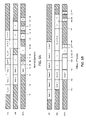
- FIG. 9A the timing of a normal operation is shown where any errors are corrected within a single sector time.
- the AFE, DBE, and error detection and correction (EDAC) show sectors of data advancing through each node in lock step (with sector time offsets).
- FIG. 9A depicts a timing diagram for an exemplary embodiment in a disc drive during normal read operation, i.e., when sectors are able to be corrected within the same time required for the AFE to capture of a sector of data. Timing is shown for the three most significant nodes of the system, namely AFE, DBE, and EDAC (error detection and correction).
- the EDAC may be implemented as a hardware engine, either internal or external to the channel, or implemented using microcode running on either or both of the system and/or channel processors. If EDAC is performed in microcode it may also be accelerated with special purpose hardware. The basic functionality is born out by a pipeline of these three components as exemplified by the figure.
- the figure shows the entire read channel as being idle prior to the first time interval, T 1 .
- the disc drive receives and responds to a request for data, positioning the head and waiting for the rotating media to provide the requested sectors to the read element on the head.
- the desired data arrives at time T 1 , at which time the AFE is directed by the formatter to begin reading data, sampling, and storing the data in the buffer memory.
- the data itself may be organized into sectors of a predetermined length (in bits), and these sectors may occur consecutively around the disc. Though shown as immediately following one another, there is usually a small gap between sectors to allow for variance in rotational speed without accidentally overwriting data. Another regularly-occurring but larger interruption in the stream of data may be due to servo wedges. These are special radial wedges that may be written periodically around the disc to enable determination of the head's position relative to the media. In the example of FIG. 9A , a servo wedge is encountered between times T 5 and T 6 . Following the example and starting at T 1 , sector 1 is read from the media and stored in the buffer memory. This read is concluded at time T 2 . At time T 2 , the DBE is informed that there is a sector available for processing.
- the DBE may be informed before T 2 that a sector is available.
- the control logic or control program may time the DBE processing of a sector to start just late enough so that the DBE does not overtake the AFE and run out of samples to process.
- DBE processing is allowed to begin immediately, but must pause whenever it runs out of samples to process. Waiting to begin DBE processing until T 2 is an exemplary scheme, and the extra latency (delay) in the data path may be hidden by other disc drive system level latencies.
- the AFE and the DBE may be run from the same clock signal, but in a disc drive application where the disc is divided into data rate zones, the AFE's clock should approximately match the disc drive data rate which changes for each zone. It may be simpler in implementation to allow the DBE to run from a fixed rate clock that is never less than the maximum AFE clock rate. If the DBE is run from a fixed rate clock then it will process samples much faster than the AFE can capture samples in a low data rate zone. It will be advantageous if the DBE clock is also faster than the AFE clock in the highest data rate zone. In this way the DBE's GPCP is given extra clock cycles in which to complete the execution of any overhead or extra microcode that may be necessary to complete processing of a sector. The faster clock will also allow the DBE to fall behind the AFE, allowing samples to accumulate in the memory, and catch up later.
- the DBE may choose to begin processing the sector.
- the control (by logic or by program) may choose to delay the processing of a sector if it has other higher-priority work to do.
- the DBE processes sector 1 immediately.
- This example also depicts a request to read multiple (6) sectors, so while the DBE processes sector 1 , the AFE begins capturing the samples for sector 2 .
- both the AFE and the DBE complete their respective tasks and move on to the next sector.
- the DBE may start earlier, either as soon as the first sample is available from the buffer memory (if the DBE is allowed to stall at times when the next sample is unavailable), or as soon as enough samples are available in buffer memory that the DBE will not starve for samples during its processing of the sector.
- the buffer memory may respond like a FIFO (first-in-first-out) memory device.
- the DBE does not start until all the samples are available in the memory, and it will be understood by one skilled in the art that this may provide a simpler implementation when the DBE runs on a faster clock than the AFE.
- sector 1 is sent to the error detection and correction engine via an intermediary memory unit, which may be the same buffer memory used for samples, while sector 2 is processed by the DBE and sector 3 is captured by the AFE.
- FIG. 9A shows an example in which sector 1 requires a full sector time to correct. This is not the case for all sectors, as other sectors may complete the EDAC process early.
- Sector 1 is depicted as requiring the maximum possible on-the-fly correction, defined to be the maximum level of correction that can be done in a sector time.
- the EDAC operation for sector 1 concludes just in time to begin the EDAC processing of sector 2 at the normal time.
- the EDAC processing of sector 2 is shown to complete early, at T 6 .
- T 5 the normal pipeline operation is disrupted slightly by a servo wedge that is read by the AFE and sent to separate servo demodulation hardware.
- the servo wedge produces a gap in the normal DBE processing schedule between T 8 and T 9 and again in the EDAC processing schedule between T 10 and T 11 , even if sector 3 requires the maximum on-the-fly correction. It will be seen that if sector 3 required more than the maximum on-the-fly correction, additional processing time in the EDAC engine is available during the servo-created gap between T 10 and T 11 .
- the system may be capable of correcting, for example, 15 errors within one sector time. However, if more than 15 errors are detected in a sector being processed, then the system need not stop accepting the incoming input signal. By allowing the incoming signal to accumulate either as samples from the AFE or as uncorrected information bits from the DBE in the channel buffer for later processing and/or correction, the system may be operated to continue to make corrections that extend past the 15 error limit for a sector time. After all the errors have been corrected for the current sector, the DBE may be operated to “catch back up” with the AFE by processing the samples stored in the buffer and the EDAC may be operated to “catch back up” with the DBE by correcting uncorrected bits stored in the buffer.
- extended ECC correction This technique may be referred to as extended ECC correction. If the EDAC is capable of more than the maximum on-the-fly correction, then the ability in the present invention of the DBE and EDAC to “catch back up” enables extended ECC correction. In order to take advantage of extended ECC correction, enough parity bits (in ECC symbols) must have been written to the disc to support the extended ECC correction, but this is well known to those skilled in the art. The normal pipeline sequence of operations is shown to resume after the gap at T 11 , the gap having been created by the servo wedge.
- sector 1 includes errors that are not correctable within one sector time.
- the system continues to read sequential sectors by storing samples in the buffer memory for later processing. Accordingly, the identification of an error in sector 1 , uncorrectable within one sector time, does not interrupt the read operation for the AFE.
- the AFE continues to produce and store samples in the memory until the memory is full or the multiple read operation is complete.
- the uncorrectable error does not immediately interrupt the processing in the DBE.
- the EDAC at time T 23 and continuing to time T 25 , extends its correction time into the time slot that normally would have been allocated to sector 2 and part of sector 3 .
- the extended ECC correction is illustrated as if it is also unsuccessful. Having exhausted the full, extended correction power at time T 25 , the control logic or control program determines that sector 1 is uncorrectable, and yet even here the AFE may continue to capture samples for sector 5 as shown, storing them in the memory. The DBE, however, chooses or is instructed by control logic to retry the samples for sector 1 still stored in the buffer as soon as the DBE completes the processing of the sector it is working on at time T 25 . While the DBE retries sector 1 , the AFE continues to capture and store samples for sector 6 .
- the EDAC has completed its work on sector 1 and “catches back up” on sectors 2 , 3 , and 4 , which in this example contain fewer errors and correct in a much shorter period of time.
- the decoupled processing may continue for as long as the control logic or program can manage the complexity or for as long as sufficient memory exists to store samples and/or uncorrected bits.
- the AFE and DBE portions of the system can operate efficiently and, in this example, in different sequences and at different processing rates, without re-reading the physical sector. It is up to the control logic or control program to determine how best to schedule the processing of the AFE, the DBE, and the EDAC as well as how best to manage the limited memory space in the buffer.
- AFE, DBE, controller, buffer memory, and their sub components may be integrated on a single integrated circuit (IC), or implemented using discrete components and one or more ICs.
- the functions and processes (including algorithms) may be performed in hardware, software, or a combination thereof. Accordingly, other embodiments are within the scope of the following claims.
Abstract
Description
-
- a. Before or after filtering the sequence is shifted forward in time to offset the effects of any pipeline delays known to be in the gain loop hardware (either before the gain error estimate or after the loop compensation filter).
- b. After applying a normal filter, the entire resulting sequence is shifted forward in time to offset the effect of the group delay of the filter.
- c. After applying the filter in the forward direction, the entire resulting sequence is time-reversed, passed through the filter again, and time-reversed again. This is a well known signal processing method for filtering with no group delay.
- d. The filter may be a non-linear process that searches for sudden changes in gain, like a defect on the media, and produces a filtered sequence that responds to the sudden change immediately (with no delay). This could be analogous to the edge detection algorithms used for image processing simplified for a one-dimensional image (the sequence of gain error estimates).
Claims (6)
Priority Applications (1)
| Application Number | Priority Date | Filing Date | Title |
|---|---|---|---|
| US10/883,633 US7196644B1 (en) | 2004-07-01 | 2004-07-01 | Decoupling of analog input and digital output |
Applications Claiming Priority (1)
| Application Number | Priority Date | Filing Date | Title |
|---|---|---|---|
| US10/883,633 US7196644B1 (en) | 2004-07-01 | 2004-07-01 | Decoupling of analog input and digital output |
Publications (1)
| Publication Number | Publication Date |
|---|---|
| US7196644B1 true US7196644B1 (en) | 2007-03-27 |
Family
ID=37886084
Family Applications (1)
| Application Number | Title | Priority Date | Filing Date |
|---|---|---|---|
| US10/883,633 Active 2024-12-26 US7196644B1 (en) | 2004-07-01 | 2004-07-01 | Decoupling of analog input and digital output |
Country Status (1)
| Country | Link |
|---|---|
| US (1) | US7196644B1 (en) |
Cited By (59)
| Publication number | Priority date | Publication date | Assignee | Title |
|---|---|---|---|---|
| US20050114894A1 (en) * | 2003-11-26 | 2005-05-26 | David Hoerl | System for video digitization and image correction for use with a computer management system |
| US20080219050A1 (en) * | 2007-01-24 | 2008-09-11 | Anobit Technologies Ltd. | Reduction of back pattern dependency effects in memory devices |
| US20090024905A1 (en) * | 2006-05-12 | 2009-01-22 | Anobit Technologies Ltd. | Combined distortion estimation and error correction coding for memory devices |
| US20090144600A1 (en) * | 2007-11-30 | 2009-06-04 | Anobit Technologies Ltd | Efficient re-read operations from memory devices |
| US20100115376A1 (en) * | 2006-12-03 | 2010-05-06 | Anobit Technologies Ltd. | Automatic defect management in memory devices |
| US20100124088A1 (en) * | 2008-11-16 | 2010-05-20 | Anobit Technologies Ltd | Storage at m bits/cell density in n bits/cell analog memory cell devices, m>n |
| KR20110015279A (en) * | 2009-08-07 | 2011-02-15 | 삼성전자주식회사 | Non-volatile memory device outputting analog signal and memory system having the same |
| US8145984B2 (en) | 2006-10-30 | 2012-03-27 | Anobit Technologies Ltd. | Reading memory cells using multiple thresholds |
| US8156398B2 (en) | 2008-02-05 | 2012-04-10 | Anobit Technologies Ltd. | Parameter estimation based on error correction code parity check equations |
| US8169825B1 (en) | 2008-09-02 | 2012-05-01 | Anobit Technologies Ltd. | Reliable data storage in analog memory cells subjected to long retention periods |
| US8174905B2 (en) | 2007-09-19 | 2012-05-08 | Anobit Technologies Ltd. | Programming orders for reducing distortion in arrays of multi-level analog memory cells |
| US8174857B1 (en) | 2008-12-31 | 2012-05-08 | Anobit Technologies Ltd. | Efficient readout schemes for analog memory cell devices using multiple read threshold sets |
| US8209588B2 (en) | 2007-12-12 | 2012-06-26 | Anobit Technologies Ltd. | Efficient interference cancellation in analog memory cell arrays |
| US8228701B2 (en) | 2009-03-01 | 2012-07-24 | Apple Inc. | Selective activation of programming schemes in analog memory cell arrays |
| US8230300B2 (en) | 2008-03-07 | 2012-07-24 | Apple Inc. | Efficient readout from analog memory cells using data compression |
| US8234545B2 (en) | 2007-05-12 | 2012-07-31 | Apple Inc. | Data storage with incremental redundancy |
| US8239735B2 (en) | 2006-05-12 | 2012-08-07 | Apple Inc. | Memory Device with adaptive capacity |
| US8239734B1 (en) | 2008-10-15 | 2012-08-07 | Apple Inc. | Efficient data storage in storage device arrays |
| US8238157B1 (en) | 2009-04-12 | 2012-08-07 | Apple Inc. | Selective re-programming of analog memory cells |
| US8248831B2 (en) | 2008-12-31 | 2012-08-21 | Apple Inc. | Rejuvenation of analog memory cells |
| US8259506B1 (en) | 2009-03-25 | 2012-09-04 | Apple Inc. | Database of memory read thresholds |
| US8259497B2 (en) | 2007-08-06 | 2012-09-04 | Apple Inc. | Programming schemes for multi-level analog memory cells |
| US8261159B1 (en) | 2008-10-30 | 2012-09-04 | Apple, Inc. | Data scrambling schemes for memory devices |
| US8270246B2 (en) | 2007-11-13 | 2012-09-18 | Apple Inc. | Optimized selection of memory chips in multi-chips memory devices |
| US8369141B2 (en) | 2007-03-12 | 2013-02-05 | Apple Inc. | Adaptive estimation of memory cell read thresholds |
| US8400858B2 (en) | 2008-03-18 | 2013-03-19 | Apple Inc. | Memory device with reduced sense time readout |
| US8429493B2 (en) | 2007-05-12 | 2013-04-23 | Apple Inc. | Memory device with internal signap processing unit |
| US8479080B1 (en) | 2009-07-12 | 2013-07-02 | Apple Inc. | Adaptive over-provisioning in memory systems |
| US8482978B1 (en) | 2008-09-14 | 2013-07-09 | Apple Inc. | Estimation of memory cell read thresholds by sampling inside programming level distribution intervals |
| US8493783B2 (en) | 2008-03-18 | 2013-07-23 | Apple Inc. | Memory device readout using multiple sense times |
| US8493781B1 (en) | 2010-08-12 | 2013-07-23 | Apple Inc. | Interference mitigation using individual word line erasure operations |
| US8495465B1 (en) | 2009-10-15 | 2013-07-23 | Apple Inc. | Error correction coding over multiple memory pages |
| US8498151B1 (en) | 2008-08-05 | 2013-07-30 | Apple Inc. | Data storage in analog memory cells using modified pass voltages |
| US8527819B2 (en) | 2007-10-19 | 2013-09-03 | Apple Inc. | Data storage in analog memory cell arrays having erase failures |
| US8572423B1 (en) | 2010-06-22 | 2013-10-29 | Apple Inc. | Reducing peak current in memory systems |
| US8572311B1 (en) | 2010-01-11 | 2013-10-29 | Apple Inc. | Redundant data storage in multi-die memory systems |
| US8570804B2 (en) | 2006-05-12 | 2013-10-29 | Apple Inc. | Distortion estimation and cancellation in memory devices |
| US8595591B1 (en) | 2010-07-11 | 2013-11-26 | Apple Inc. | Interference-aware assignment of programming levels in analog memory cells |
| US20130322511A1 (en) * | 2012-05-29 | 2013-12-05 | Hughes Network Systems, Llc | Method and apparatus for synchronization of data and error samples in a communications system |
| US8631311B1 (en) * | 2011-04-21 | 2014-01-14 | Sk Hynix Memory Solutions Inc. | Data recovery using existing reconfigurable read channel hardware |
| US8645794B1 (en) | 2010-07-31 | 2014-02-04 | Apple Inc. | Data storage in analog memory cells using a non-integer number of bits per cell |
| US8677054B1 (en) | 2009-12-16 | 2014-03-18 | Apple Inc. | Memory management schemes for non-volatile memory devices |
| US8694854B1 (en) | 2010-08-17 | 2014-04-08 | Apple Inc. | Read threshold setting based on soft readout statistics |
| US8694814B1 (en) | 2010-01-10 | 2014-04-08 | Apple Inc. | Reuse of host hibernation storage space by memory controller |
| US8694853B1 (en) | 2010-05-04 | 2014-04-08 | Apple Inc. | Read commands for reading interfering memory cells |
| US8832354B2 (en) | 2009-03-25 | 2014-09-09 | Apple Inc. | Use of host system resources by memory controller |
| US8856475B1 (en) | 2010-08-01 | 2014-10-07 | Apple Inc. | Efficient selection of memory blocks for compaction |
| TWI461959B (en) * | 2012-04-26 | 2014-11-21 | Issc Technologies Corp | Output and input interface apparatus |
| US8924661B1 (en) | 2009-01-18 | 2014-12-30 | Apple Inc. | Memory system including a controller and processors associated with memory devices |
| US8949684B1 (en) | 2008-09-02 | 2015-02-03 | Apple Inc. | Segmented data storage |
| US20150100852A1 (en) * | 2013-10-07 | 2015-04-09 | Macronix International Co., Ltd. | Ecc method for double pattern flash memory |
| US9021181B1 (en) | 2010-09-27 | 2015-04-28 | Apple Inc. | Memory management for unifying memory cell conditions by using maximum time intervals |
| US9081684B2 (en) | 2013-08-28 | 2015-07-14 | Landis+Gyr Technologies, Llc | Data recovery of data symbols received in error |
| US9104580B1 (en) | 2010-07-27 | 2015-08-11 | Apple Inc. | Cache memory for hybrid disk drives |
| US9495244B2 (en) * | 2013-11-11 | 2016-11-15 | Seagate Technology Llc | Dynamic per-decoder control of log likelihood ratio and decoding parameters |
| US9525462B1 (en) | 2015-12-04 | 2016-12-20 | Landis+Gyr Technologies, Llc | Data recovery of data symbols |
| US9535785B2 (en) | 2014-01-17 | 2017-01-03 | Macronix International Co., Ltd. | ECC method for flash memory |
| US11556416B2 (en) | 2021-05-05 | 2023-01-17 | Apple Inc. | Controlling memory readout reliability and throughput by adjusting distance between read thresholds |
| US11847342B2 (en) | 2021-07-28 | 2023-12-19 | Apple Inc. | Efficient transfer of hard data and confidence levels in reading a nonvolatile memory |
Citations (19)
| Publication number | Priority date | Publication date | Assignee | Title |
|---|---|---|---|---|
| US5255136A (en) | 1990-08-17 | 1993-10-19 | Quantum Corporation | High capacity submicro-winchester fixed disk drive |
| US5402171A (en) * | 1992-09-11 | 1995-03-28 | Kabushiki Kaisha Toshiba | Electronic still camera with improved picture resolution by image shifting in a parallelogram arrangement |
| US5588027A (en) * | 1993-01-30 | 1996-12-24 | Samsung Electronics Co., Ltd. | Digital demodulating method and circuit for use in a time-division multiple access channel |
| US5696639A (en) | 1995-05-12 | 1997-12-09 | Cirrus Logic, Inc. | Sampled amplitude read channel employing interpolated timing recovery |
| US5726818A (en) | 1995-12-05 | 1998-03-10 | Cirrus Logic, Inc. | Magnetic disk sampled amplitude read channel employing interpolated timing recovery for synchronous detection of embedded servo data |
| US5760984A (en) | 1995-10-20 | 1998-06-02 | Cirrus Logic, Inc. | Cost reduced interpolated timing recovery in a sampled amplitude read channel |
| US5812334A (en) | 1993-02-01 | 1998-09-22 | Cirrus Logic, Inc. | Synchronous read channel employing discrete timing recovery, transition detector, and sequence detector |
| US5829011A (en) | 1997-01-31 | 1998-10-27 | Texas Instruments Incorporated | Apparatus and method of exchanging data and operational parameters in a mass storage system |
| US5835295A (en) | 1996-11-18 | 1998-11-10 | Cirrus Logice, Inc. | Zero phase restart interpolated timing recovery in a sampled amplitude read channel |
| US5880707A (en) * | 1994-10-20 | 1999-03-09 | Canon Kabushiki Kaisha | Display control apparatus and method |
| US5892632A (en) | 1996-11-18 | 1999-04-06 | Cirrus Logic, Inc. | Sampled amplitude read channel employing a residue number system FIR filter in an adaptive equalizer and in interpolated timing recovery |
| US6009549A (en) | 1997-05-15 | 1999-12-28 | Cirrus Logic, Inc. | Disk storage system employing error detection and correction of channel coded data, interpolated timing recovery, and retroactive/split-segment symbol synchronization |
| US6078453A (en) | 1997-11-12 | 2000-06-20 | Western Digital Corporation | Method and apparatus for optimizing the servo read channel of a hard disk drive |
| US6097769A (en) | 1998-02-10 | 2000-08-01 | Lucent Technologies Inc. | Viterbi detector using path memory controlled by best state information |
| US6111710A (en) | 1997-06-25 | 2000-08-29 | Cirrus Logic, Inc. | Asynchronous/synchronous gain control for interpolated timing recovery in a sampled amplitude read channel |
| US6369741B1 (en) | 1999-07-16 | 2002-04-09 | Stmicroelectronics S.R.L. | Optimization of the parameters of a pre-equalization low pass filter for a read channel |
| US6480349B1 (en) | 2000-02-25 | 2002-11-12 | Western Digital Technologies, Inc. | Disk drive employing a non-volatile semiconductor memory for storing read channel parameter calibrated for the disk drive used to recover disk channel parameter |
| US6570611B1 (en) * | 1999-01-29 | 2003-05-27 | Matsushita Electric Industrial Co., Ltd. | Image display |
| US6747640B2 (en) * | 2000-10-24 | 2004-06-08 | Mitsubishi Denki Kabushiki Kaisha | Image display device and image display method |
-
2004
- 2004-07-01 US US10/883,633 patent/US7196644B1/en active Active
Patent Citations (20)
| Publication number | Priority date | Publication date | Assignee | Title |
|---|---|---|---|---|
| US5255136A (en) | 1990-08-17 | 1993-10-19 | Quantum Corporation | High capacity submicro-winchester fixed disk drive |
| US5402171A (en) * | 1992-09-11 | 1995-03-28 | Kabushiki Kaisha Toshiba | Electronic still camera with improved picture resolution by image shifting in a parallelogram arrangement |
| US5588027A (en) * | 1993-01-30 | 1996-12-24 | Samsung Electronics Co., Ltd. | Digital demodulating method and circuit for use in a time-division multiple access channel |
| US5812334A (en) | 1993-02-01 | 1998-09-22 | Cirrus Logic, Inc. | Synchronous read channel employing discrete timing recovery, transition detector, and sequence detector |
| US5880707A (en) * | 1994-10-20 | 1999-03-09 | Canon Kabushiki Kaisha | Display control apparatus and method |
| US5696639A (en) | 1995-05-12 | 1997-12-09 | Cirrus Logic, Inc. | Sampled amplitude read channel employing interpolated timing recovery |
| US5909332A (en) | 1995-05-12 | 1999-06-01 | Cirrus Logic, Inc. | Sampled amplitude read channel employing interpolated timing recovery |
| US5760984A (en) | 1995-10-20 | 1998-06-02 | Cirrus Logic, Inc. | Cost reduced interpolated timing recovery in a sampled amplitude read channel |
| US5726818A (en) | 1995-12-05 | 1998-03-10 | Cirrus Logic, Inc. | Magnetic disk sampled amplitude read channel employing interpolated timing recovery for synchronous detection of embedded servo data |
| US5892632A (en) | 1996-11-18 | 1999-04-06 | Cirrus Logic, Inc. | Sampled amplitude read channel employing a residue number system FIR filter in an adaptive equalizer and in interpolated timing recovery |
| US5835295A (en) | 1996-11-18 | 1998-11-10 | Cirrus Logice, Inc. | Zero phase restart interpolated timing recovery in a sampled amplitude read channel |
| US5829011A (en) | 1997-01-31 | 1998-10-27 | Texas Instruments Incorporated | Apparatus and method of exchanging data and operational parameters in a mass storage system |
| US6009549A (en) | 1997-05-15 | 1999-12-28 | Cirrus Logic, Inc. | Disk storage system employing error detection and correction of channel coded data, interpolated timing recovery, and retroactive/split-segment symbol synchronization |
| US6111710A (en) | 1997-06-25 | 2000-08-29 | Cirrus Logic, Inc. | Asynchronous/synchronous gain control for interpolated timing recovery in a sampled amplitude read channel |
| US6078453A (en) | 1997-11-12 | 2000-06-20 | Western Digital Corporation | Method and apparatus for optimizing the servo read channel of a hard disk drive |
| US6097769A (en) | 1998-02-10 | 2000-08-01 | Lucent Technologies Inc. | Viterbi detector using path memory controlled by best state information |
| US6570611B1 (en) * | 1999-01-29 | 2003-05-27 | Matsushita Electric Industrial Co., Ltd. | Image display |
| US6369741B1 (en) | 1999-07-16 | 2002-04-09 | Stmicroelectronics S.R.L. | Optimization of the parameters of a pre-equalization low pass filter for a read channel |
| US6480349B1 (en) | 2000-02-25 | 2002-11-12 | Western Digital Technologies, Inc. | Disk drive employing a non-volatile semiconductor memory for storing read channel parameter calibrated for the disk drive used to recover disk channel parameter |
| US6747640B2 (en) * | 2000-10-24 | 2004-06-08 | Mitsubishi Denki Kabushiki Kaisha | Image display device and image display method |
Cited By (80)
| Publication number | Priority date | Publication date | Assignee | Title |
|---|---|---|---|---|
| US20050114894A1 (en) * | 2003-11-26 | 2005-05-26 | David Hoerl | System for video digitization and image correction for use with a computer management system |
| US8683024B2 (en) * | 2003-11-26 | 2014-03-25 | Riip, Inc. | System for video digitization and image correction for use with a computer management system |
| US8156403B2 (en) | 2006-05-12 | 2012-04-10 | Anobit Technologies Ltd. | Combined distortion estimation and error correction coding for memory devices |
| US20090024905A1 (en) * | 2006-05-12 | 2009-01-22 | Anobit Technologies Ltd. | Combined distortion estimation and error correction coding for memory devices |
| US8570804B2 (en) | 2006-05-12 | 2013-10-29 | Apple Inc. | Distortion estimation and cancellation in memory devices |
| US8599611B2 (en) | 2006-05-12 | 2013-12-03 | Apple Inc. | Distortion estimation and cancellation in memory devices |
| US8239735B2 (en) | 2006-05-12 | 2012-08-07 | Apple Inc. | Memory Device with adaptive capacity |
| US8145984B2 (en) | 2006-10-30 | 2012-03-27 | Anobit Technologies Ltd. | Reading memory cells using multiple thresholds |
| USRE46346E1 (en) | 2006-10-30 | 2017-03-21 | Apple Inc. | Reading memory cells using multiple thresholds |
| US8151163B2 (en) | 2006-12-03 | 2012-04-03 | Anobit Technologies Ltd. | Automatic defect management in memory devices |
| US20100115376A1 (en) * | 2006-12-03 | 2010-05-06 | Anobit Technologies Ltd. | Automatic defect management in memory devices |
| US20080219050A1 (en) * | 2007-01-24 | 2008-09-11 | Anobit Technologies Ltd. | Reduction of back pattern dependency effects in memory devices |
| US8151166B2 (en) | 2007-01-24 | 2012-04-03 | Anobit Technologies Ltd. | Reduction of back pattern dependency effects in memory devices |
| US8369141B2 (en) | 2007-03-12 | 2013-02-05 | Apple Inc. | Adaptive estimation of memory cell read thresholds |
| US8234545B2 (en) | 2007-05-12 | 2012-07-31 | Apple Inc. | Data storage with incremental redundancy |
| US8429493B2 (en) | 2007-05-12 | 2013-04-23 | Apple Inc. | Memory device with internal signap processing unit |
| US8259497B2 (en) | 2007-08-06 | 2012-09-04 | Apple Inc. | Programming schemes for multi-level analog memory cells |
| US8174905B2 (en) | 2007-09-19 | 2012-05-08 | Anobit Technologies Ltd. | Programming orders for reducing distortion in arrays of multi-level analog memory cells |
| US8527819B2 (en) | 2007-10-19 | 2013-09-03 | Apple Inc. | Data storage in analog memory cell arrays having erase failures |
| US8270246B2 (en) | 2007-11-13 | 2012-09-18 | Apple Inc. | Optimized selection of memory chips in multi-chips memory devices |
| US8990659B2 (en) * | 2007-11-30 | 2015-03-24 | Apple Inc. | Efficient re-read operations in analog memory cell arrays |
| US8225181B2 (en) * | 2007-11-30 | 2012-07-17 | Apple Inc. | Efficient re-read operations from memory devices |
| US20090144600A1 (en) * | 2007-11-30 | 2009-06-04 | Anobit Technologies Ltd | Efficient re-read operations from memory devices |
| US8769381B2 (en) * | 2007-11-30 | 2014-07-01 | Apple Inc. | Efficient re-read operations in analog memory cell arrays |
| US8782497B2 (en) * | 2007-11-30 | 2014-07-15 | Apple Inc. | Efficient re-read operations in analog memory cell arrays |
| US20140325308A1 (en) * | 2007-11-30 | 2014-10-30 | Apple Inc. | Efficient Re-read Operations in Analog Memory Cell Arrays |
| US8209588B2 (en) | 2007-12-12 | 2012-06-26 | Anobit Technologies Ltd. | Efficient interference cancellation in analog memory cell arrays |
| US8156398B2 (en) | 2008-02-05 | 2012-04-10 | Anobit Technologies Ltd. | Parameter estimation based on error correction code parity check equations |
| US8230300B2 (en) | 2008-03-07 | 2012-07-24 | Apple Inc. | Efficient readout from analog memory cells using data compression |
| US8493783B2 (en) | 2008-03-18 | 2013-07-23 | Apple Inc. | Memory device readout using multiple sense times |
| US8400858B2 (en) | 2008-03-18 | 2013-03-19 | Apple Inc. | Memory device with reduced sense time readout |
| US8498151B1 (en) | 2008-08-05 | 2013-07-30 | Apple Inc. | Data storage in analog memory cells using modified pass voltages |
| US8169825B1 (en) | 2008-09-02 | 2012-05-01 | Anobit Technologies Ltd. | Reliable data storage in analog memory cells subjected to long retention periods |
| US8949684B1 (en) | 2008-09-02 | 2015-02-03 | Apple Inc. | Segmented data storage |
| US8482978B1 (en) | 2008-09-14 | 2013-07-09 | Apple Inc. | Estimation of memory cell read thresholds by sampling inside programming level distribution intervals |
| US8239734B1 (en) | 2008-10-15 | 2012-08-07 | Apple Inc. | Efficient data storage in storage device arrays |
| US8713330B1 (en) | 2008-10-30 | 2014-04-29 | Apple Inc. | Data scrambling in memory devices |
| US8261159B1 (en) | 2008-10-30 | 2012-09-04 | Apple, Inc. | Data scrambling schemes for memory devices |
| US20100124088A1 (en) * | 2008-11-16 | 2010-05-20 | Anobit Technologies Ltd | Storage at m bits/cell density in n bits/cell analog memory cell devices, m>n |
| US8208304B2 (en) | 2008-11-16 | 2012-06-26 | Anobit Technologies Ltd. | Storage at M bits/cell density in N bits/cell analog memory cell devices, M>N |
| US8174857B1 (en) | 2008-12-31 | 2012-05-08 | Anobit Technologies Ltd. | Efficient readout schemes for analog memory cell devices using multiple read threshold sets |
| US8248831B2 (en) | 2008-12-31 | 2012-08-21 | Apple Inc. | Rejuvenation of analog memory cells |
| US8397131B1 (en) | 2008-12-31 | 2013-03-12 | Apple Inc. | Efficient readout schemes for analog memory cell devices |
| US8374014B2 (en) | 2008-12-31 | 2013-02-12 | Apple Inc. | Rejuvenation of analog memory cells |
| US8924661B1 (en) | 2009-01-18 | 2014-12-30 | Apple Inc. | Memory system including a controller and processors associated with memory devices |
| US8228701B2 (en) | 2009-03-01 | 2012-07-24 | Apple Inc. | Selective activation of programming schemes in analog memory cell arrays |
| US8832354B2 (en) | 2009-03-25 | 2014-09-09 | Apple Inc. | Use of host system resources by memory controller |
| US8259506B1 (en) | 2009-03-25 | 2012-09-04 | Apple Inc. | Database of memory read thresholds |
| US8238157B1 (en) | 2009-04-12 | 2012-08-07 | Apple Inc. | Selective re-programming of analog memory cells |
| US8479080B1 (en) | 2009-07-12 | 2013-07-02 | Apple Inc. | Adaptive over-provisioning in memory systems |
| KR20110015279A (en) * | 2009-08-07 | 2011-02-15 | 삼성전자주식회사 | Non-volatile memory device outputting analog signal and memory system having the same |
| US8495465B1 (en) | 2009-10-15 | 2013-07-23 | Apple Inc. | Error correction coding over multiple memory pages |
| US8677054B1 (en) | 2009-12-16 | 2014-03-18 | Apple Inc. | Memory management schemes for non-volatile memory devices |
| US8694814B1 (en) | 2010-01-10 | 2014-04-08 | Apple Inc. | Reuse of host hibernation storage space by memory controller |
| US8677203B1 (en) | 2010-01-11 | 2014-03-18 | Apple Inc. | Redundant data storage schemes for multi-die memory systems |
| US8572311B1 (en) | 2010-01-11 | 2013-10-29 | Apple Inc. | Redundant data storage in multi-die memory systems |
| US8694853B1 (en) | 2010-05-04 | 2014-04-08 | Apple Inc. | Read commands for reading interfering memory cells |
| US8572423B1 (en) | 2010-06-22 | 2013-10-29 | Apple Inc. | Reducing peak current in memory systems |
| US8595591B1 (en) | 2010-07-11 | 2013-11-26 | Apple Inc. | Interference-aware assignment of programming levels in analog memory cells |
| US9104580B1 (en) | 2010-07-27 | 2015-08-11 | Apple Inc. | Cache memory for hybrid disk drives |
| US8767459B1 (en) | 2010-07-31 | 2014-07-01 | Apple Inc. | Data storage in analog memory cells across word lines using a non-integer number of bits per cell |
| US8645794B1 (en) | 2010-07-31 | 2014-02-04 | Apple Inc. | Data storage in analog memory cells using a non-integer number of bits per cell |
| US8856475B1 (en) | 2010-08-01 | 2014-10-07 | Apple Inc. | Efficient selection of memory blocks for compaction |
| US8493781B1 (en) | 2010-08-12 | 2013-07-23 | Apple Inc. | Interference mitigation using individual word line erasure operations |
| US8694854B1 (en) | 2010-08-17 | 2014-04-08 | Apple Inc. | Read threshold setting based on soft readout statistics |
| US9021181B1 (en) | 2010-09-27 | 2015-04-28 | Apple Inc. | Memory management for unifying memory cell conditions by using maximum time intervals |
| US8631311B1 (en) * | 2011-04-21 | 2014-01-14 | Sk Hynix Memory Solutions Inc. | Data recovery using existing reconfigurable read channel hardware |
| TWI461959B (en) * | 2012-04-26 | 2014-11-21 | Issc Technologies Corp | Output and input interface apparatus |
| US20130322511A1 (en) * | 2012-05-29 | 2013-12-05 | Hughes Network Systems, Llc | Method and apparatus for synchronization of data and error samples in a communications system |
| US8929501B2 (en) * | 2012-05-29 | 2015-01-06 | Hughes Network Systems, Llc | Method and apparatus for synchronization of data and error samples in a communications system |
| US9081684B2 (en) | 2013-08-28 | 2015-07-14 | Landis+Gyr Technologies, Llc | Data recovery of data symbols received in error |
| US9146809B2 (en) * | 2013-10-07 | 2015-09-29 | Macronix International Co., Ltd. | ECC method for double pattern flash memory |
| US20150100852A1 (en) * | 2013-10-07 | 2015-04-09 | Macronix International Co., Ltd. | Ecc method for double pattern flash memory |
| US9760434B2 (en) | 2013-10-07 | 2017-09-12 | Macronix International Co., Ltd. | ECC method for double pattern flash memory |
| US9495244B2 (en) * | 2013-11-11 | 2016-11-15 | Seagate Technology Llc | Dynamic per-decoder control of log likelihood ratio and decoding parameters |
| US9535785B2 (en) | 2014-01-17 | 2017-01-03 | Macronix International Co., Ltd. | ECC method for flash memory |
| US9525462B1 (en) | 2015-12-04 | 2016-12-20 | Landis+Gyr Technologies, Llc | Data recovery of data symbols |
| US10250294B2 (en) | 2015-12-04 | 2019-04-02 | Landis+Gyr Technologies, Llc | Data recovery of data symbols |
| US11556416B2 (en) | 2021-05-05 | 2023-01-17 | Apple Inc. | Controlling memory readout reliability and throughput by adjusting distance between read thresholds |
| US11847342B2 (en) | 2021-07-28 | 2023-12-19 | Apple Inc. | Efficient transfer of hard data and confidence levels in reading a nonvolatile memory |
Similar Documents
| Publication | Publication Date | Title |
|---|---|---|
| US7196644B1 (en) | Decoupling of analog input and digital output | |
| US7365671B1 (en) | Communication channel with undersampled interpolative timing recovery | |
| US6937415B2 (en) | Method and apparatus for enhanced data channel performance using read sample buffering | |
| US6519715B1 (en) | Signal processing apparatus and a data recording and reproducing apparatus including local memory processor | |
| US7203017B1 (en) | Timing recovery for data storage channels with buffered sectors | |
| KR100555277B1 (en) | Servo demodulator and method for synchronous servo demodulation | |
| US7733591B2 (en) | Data storage device with data recovery process using fixed phase clocking for analog-to-digital conversion | |
| US7733592B2 (en) | Methods for multi-channel data detection phase locked loop frequency error combination | |
| US8266505B2 (en) | Systems and methods for retimed virtual data processing | |
| US20100229031A1 (en) | Systems and Methods for Recovering Information from a Defective Medium | |
| KR100545592B1 (en) | Fault Detectors and Detection Methods in Magnetic Media of Mass Storage Systems | |
| US10608808B1 (en) | Iterative recovery from baseline or timing disturbances | |
| US8122332B2 (en) | Method and apparatus for error compensation | |
| JPH1031557A (en) | Method and circuit for data synchronization using time-out counter | |
| JP3949357B2 (en) | Demodulator | |
| JP4576008B2 (en) | Signal processing apparatus and data recording / reproducing apparatus equipped with the signal processing apparatus | |
| US20020023248A1 (en) | Medium defect detection method and data storage apparatus | |
| JPH098674A (en) | Viterbi decoder | |
| US6493163B1 (en) | Increased lock range PLL for constrained data | |
| US8862971B1 (en) | Inter-track interference (ITI) correlation and cancellation for disk drive applications | |
| US20090097604A1 (en) | Methods for multi-channel data detection phase locked loop error combination | |
| US8838660B2 (en) | Systems and methods for reducing filter sensitivities | |
| US7522680B2 (en) | Apparatus, system, and method for asymmetric maximum likelihood detection | |
| JP2000299621A (en) | Phase shift calculation method for finite impulse response and execution system | |
| JP4682182B2 (en) | Data demodulator |
Legal Events
| Date | Code | Title | Description |
|---|---|---|---|
| AS | Assignment |
Owner name: SEAGATE TECHNOLOGY LLC, CALIFORNIA Free format text: ASSIGNMENT OF ASSIGNORS INTEREST;ASSIGNORS:WARREN, ROBERT W.;SILVUS, GREGORY L.;ANDERSON, KENT D.;REEL/FRAME:015907/0213;SIGNING DATES FROM 20040930 TO 20041018 |
|
| FEPP | Fee payment procedure |
Free format text: PAYOR NUMBER ASSIGNED (ORIGINAL EVENT CODE: ASPN); ENTITY STATUS OF PATENT OWNER: LARGE ENTITY Free format text: PAYER NUMBER DE-ASSIGNED (ORIGINAL EVENT CODE: RMPN); ENTITY STATUS OF PATENT OWNER: LARGE ENTITY |
|
| STCF | Information on status: patent grant |
Free format text: PATENTED CASE |
|
| CC | Certificate of correction | ||
| AS | Assignment |
Owner name: JPMORGAN CHASE BANK, N.A., AS ADMINISTRATIVE AGENT Free format text: SECURITY AGREEMENT;ASSIGNORS:MAXTOR CORPORATION;SEAGATE TECHNOLOGY LLC;SEAGATE TECHNOLOGY INTERNATIONAL;REEL/FRAME:022757/0017 Effective date: 20090507 Owner name: WELLS FARGO BANK, NATIONAL ASSOCIATION, AS COLLATE Free format text: SECURITY AGREEMENT;ASSIGNORS:MAXTOR CORPORATION;SEAGATE TECHNOLOGY LLC;SEAGATE TECHNOLOGY INTERNATIONAL;REEL/FRAME:022757/0017 Effective date: 20090507 |
|
| FPAY | Fee payment |
Year of fee payment: 4 |
|
| AS | Assignment |
Owner name: SEAGATE TECHNOLOGY INTERNATIONAL, CALIFORNIA Free format text: RELEASE;ASSIGNOR:JPMORGAN CHASE BANK, N.A., AS ADMINISTRATIVE AGENT;REEL/FRAME:025662/0001 Effective date: 20110114 Owner name: SEAGATE TECHNOLOGY LLC, CALIFORNIA Free format text: RELEASE;ASSIGNOR:JPMORGAN CHASE BANK, N.A., AS ADMINISTRATIVE AGENT;REEL/FRAME:025662/0001 Effective date: 20110114 Owner name: MAXTOR CORPORATION, CALIFORNIA Free format text: RELEASE;ASSIGNOR:JPMORGAN CHASE BANK, N.A., AS ADMINISTRATIVE AGENT;REEL/FRAME:025662/0001 Effective date: 20110114 Owner name: SEAGATE TECHNOLOGY HDD HOLDINGS, CALIFORNIA Free format text: RELEASE;ASSIGNOR:JPMORGAN CHASE BANK, N.A., AS ADMINISTRATIVE AGENT;REEL/FRAME:025662/0001 Effective date: 20110114 |
|
| AS | Assignment |
Owner name: THE BANK OF NOVA SCOTIA, AS ADMINISTRATIVE AGENT, Free format text: SECURITY AGREEMENT;ASSIGNOR:SEAGATE TECHNOLOGY LLC;REEL/FRAME:026010/0350 Effective date: 20110118 |
|
| AS | Assignment |
Owner name: SEAGATE TECHNOLOGY US HOLDINGS, INC., CALIFORNIA Free format text: TERMINATION AND RELEASE OF SECURITY INTEREST IN PATENT RIGHTS;ASSIGNOR:WELLS FARGO BANK, NATIONAL ASSOCIATION, AS COLLATERAL AGENT AND SECOND PRIORITY REPRESENTATIVE;REEL/FRAME:030833/0001 Effective date: 20130312 Owner name: SEAGATE TECHNOLOGY INTERNATIONAL, CAYMAN ISLANDS Free format text: TERMINATION AND RELEASE OF SECURITY INTEREST IN PATENT RIGHTS;ASSIGNOR:WELLS FARGO BANK, NATIONAL ASSOCIATION, AS COLLATERAL AGENT AND SECOND PRIORITY REPRESENTATIVE;REEL/FRAME:030833/0001 Effective date: 20130312 Owner name: SEAGATE TECHNOLOGY LLC, CALIFORNIA Free format text: TERMINATION AND RELEASE OF SECURITY INTEREST IN PATENT RIGHTS;ASSIGNOR:WELLS FARGO BANK, NATIONAL ASSOCIATION, AS COLLATERAL AGENT AND SECOND PRIORITY REPRESENTATIVE;REEL/FRAME:030833/0001 Effective date: 20130312 Owner name: EVAULT INC. (F/K/A I365 INC.), CALIFORNIA Free format text: TERMINATION AND RELEASE OF SECURITY INTEREST IN PATENT RIGHTS;ASSIGNOR:WELLS FARGO BANK, NATIONAL ASSOCIATION, AS COLLATERAL AGENT AND SECOND PRIORITY REPRESENTATIVE;REEL/FRAME:030833/0001 Effective date: 20130312 |
|
| FPAY | Fee payment |
Year of fee payment: 8 |
|
| MAFP | Maintenance fee payment |
Free format text: PAYMENT OF MAINTENANCE FEE, 12TH YEAR, LARGE ENTITY (ORIGINAL EVENT CODE: M1553); ENTITY STATUS OF PATENT OWNER: LARGE ENTITY Year of fee payment: 12 |