US7023651B1 - Reduction of tape velocity change backhitch time through use of an intermediate back velocity - Google Patents
Reduction of tape velocity change backhitch time through use of an intermediate back velocity Download PDFInfo
- Publication number
- US7023651B1 US7023651B1 US10/890,961 US89096104A US7023651B1 US 7023651 B1 US7023651 B1 US 7023651B1 US 89096104 A US89096104 A US 89096104A US 7023651 B1 US7023651 B1 US 7023651B1
- Authority
- US
- United States
- Prior art keywords
- velocity
- tape
- backhitch
- tape velocity
- initial
- Prior art date
- Legal status (The legal status is an assumption and is not a legal conclusion. Google has not performed a legal analysis and makes no representation as to the accuracy of the status listed.)
- Active
Links
Images


Classifications
-
- G—PHYSICS
- G11—INFORMATION STORAGE
- G11B—INFORMATION STORAGE BASED ON RELATIVE MOVEMENT BETWEEN RECORD CARRIER AND TRANSDUCER
- G11B5/00—Recording by magnetisation or demagnetisation of a record carrier; Reproducing by magnetic means; Record carriers therefor
- G11B5/48—Disposition or mounting of heads or head supports relative to record carriers ; arrangements of heads, e.g. for scanning the record carrier to increase the relative speed
- G11B5/58—Disposition or mounting of heads or head supports relative to record carriers ; arrangements of heads, e.g. for scanning the record carrier to increase the relative speed with provision for moving the head for the purpose of maintaining alignment of the head relative to the record carrier during transducing operation, e.g. to compensate for surface irregularities of the latter or for track following
- G11B5/584—Disposition or mounting of heads or head supports relative to record carriers ; arrangements of heads, e.g. for scanning the record carrier to increase the relative speed with provision for moving the head for the purpose of maintaining alignment of the head relative to the record carrier during transducing operation, e.g. to compensate for surface irregularities of the latter or for track following for track following on tapes
Definitions
- the invention relates generally to tape magnetic recording, and more particularly to optimizing tape velocity changes in response to presented host data rates.
- Data buffers are used to assist streaming of write data from a host or streaming read data out to a host.
- a buffer enables storage of data to or from data compressors to compensate for mismatches in the front end versus back end data rates and intermittency in data flow. This is needed because the host can present a variety of data rates and compressions while the drive can function at just one or a few single rates.
- Current magnetic tape storage devices include flexible magnetic tape moving from one tape spool to another while a read/write (R/W) head(s) reads or writes data from or onto the tape.
- R/W read/write
- the host and drive perform streaming R/W with few interruptions.
- the drive has to stop. Examples include: defects on tape result in errors that require retrying reading or writing at some tape location, servo tracking becomes deficient and also requires read or write retries, data buffer becomes empty of write data, or the buffer becomes full of read data.
- Stopping and restarting the tape in the drive from some given position on tape is accomplished by decelerating the tape velocity to zero at some forward position and then backwards to negative velocities with respect to the recording head. There may also be a settling time for ensuring precise tape velocity and acquisition of the proper data track by the head positioning servo system. Then the tape is accelerated until it again stops to zero velocity at some position behind the original given position. This is called the reposition point. In some cases, the tape may sit motionless at that position until given the signal to again accelerate forward to the starting point. This whole sequence is called a backhitch or football.
- FIG. 1 illustrates a conventional backhitch.
- One reason for the name football is the shape of the sequence in phase space—velocity plotted against position. Depending on how the axes are stretched or expanded, the phase plot resembles a football either lying on its side or vertically.
- Modern data tape drives tend to move tape at increasingly higher velocities and higher data rates. This has competitive advantage when the host presents or requests data at high data rates. Depending on block or record size, data compressibility, interface data rate, contention, or host limitations, the data rate to or from the host may be arbitrarily lower than maximum. In response to this, in some data transfer scenarios, there is an advantage to selectively changing the velocity at which tape moves.
- a performance advantage may exist when data buffer size is large enough so as to prevent the filling of the buffer during a football or backhitch.
- D is the native 1:1 drive rate in megabytes per second.
- B_critical ⁇ B will certainly be true at some lower velocity, v.
- B ⁇ Df host disconnect time may be required during the completion of a football. Whenever the drive is disconnected due to a football and the host is also disconnected (due to buffer-full on writes or buffer-empty on reads), then these disconnects represent wasted time that results in reduced net average host throughput, that is, lost performance. Sometimes, a portion of that lost performance can be regained by moving to a slower velocity where football time is lower.
- N capacity (D-c)/BD
- B buffer size for compressed data
- D drive rate
- c compressed data rate between the compressors and data buffer
- capacity could be total drive capacity or some other reference capacity (such as data transferred to tape during an end to end tape motion).
- This formula assumes that the buffer is being filled with write data up to size B and that the drive rate is larger than the compressed data rate.
- N is proportional to the difference (mismatch) between D and c.
- the invention involves tape data recording, and tape velocity changes in response to presented host data rates.
- Modern tape drives can adjust their tape drive velocities between two or more read/write data rates to better match the data rate demands of the host. This velocity changing may provide improvements in drive performance and total backhitch counts.
- the transition from one tape velocity to another may involve a rate change backhitch which itself could impact performance. It is desirable to reduce the time it takes to perform these transitions.
- One way to improve performance is to use a backhitch in which the back velocity has peak magnitude that is intermediate between the tape velocity going into and out of the rate change backhitch.
- One aspect within the scope of the invention involves the reducing of tape velocity change backhitch time through use of an appropriate intermediate back velocity.
- the invention contemplates a special set of these rate-change-footballs where the back velocity peak magnitude is intermediate the tape velocity going into and out of the rate-change-backhitch.
- V_in high velocity
- V_out low velocity
- a general choice might be to decelerate tape from the high incoming rate, V_in all the way to the bottom of the football so that the negative velocity at the bottom has the same magnitude as the incoming velocity at the top.
- this shape will be determined by a nearly constant value of acceleration or deceleration.
- the plot to the reposition point will then show quarters of the football that may look the same.
- Another general choice may be to progress from V_in to a back velocity of magnitude V_Out at the bottom of the football.
- calculation of the total time spent in performing the rate-change-football shows that both of these general choices are not as good as a choice contemplated by the invention in which the peak back velocity magnitude at the bottom is an intermediate value between the initial and final velocity.
- the calculation may be made directly from the phase plot via evaluation of the line integral.
- using an intermediate peak back velocity might decrease the backhitch time by 10–35% relative to using the peak back velocities of either V_in or V_Out. This can be a significant savings for high performance systems, and the invention contemplates various rate-change-footballs that involve an intermediate peak back velocity.
- Another way to improve performance in accordance with the invention is to use a backhitch in which the backhitch time is reduced through the momentary use of an intermediate forward velocity that exceeds the final tape velocity when coming out of the backhitch.
- This approach of using an intermediate forward velocity may be used in applications that may or may not utilize an intermediate peak back velocity.
- FIG. 1 shows a typical backhitch or football phase profile where the x-axis is distance and the y-axis is velocity with “+” being forward and being backward velocity;
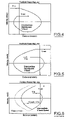
- FIG. 2 shows a possible choice for a rate-change-football from a higher to a lower velocity; the back velocity at the bottom of the football is equal in magnitude to the high velocity in;
- FIG. 3 shows another possible choice for a velocity change down; the magnitude of the back velocity at the bottom is the final velocity out;
- FIG. 4 shows an improved choice for a velocity change down; the magnitude of the back velocity at the bottom is an intermediate velocity between the velocities in and out;
- FIG. 5 shows a rate-change-football from low velocity to high velocity using an intermediate back velocity
- FIG. 6 shows three possible football phase plots from low velocity to high velocity with the middle plot having an intermediate back velocity; this illustrates the relationship among the different possibilities
- FIGS. 7 A–B show buffer waveforms when changing tape velocity upwards or downwards
- FIG. 8 is a block diagram of the data path from host to drive adaptor to compressors to data buffer to read/write drive.
- FIG. 9 shows a rate-change-football from high velocity to low velocity primarily using a back velocity with magnitude equal to the initial high velocity, but with the final approach towards the low velocity using an intermediate forward velocity according to an additional aspect of the invention.
- optimal back velocity is found by taking the derivative of the total time with respect to the back velocity, setting it to zero, and solving for the unknown optimal back velocity that gives minimal time.
- the shape may not be symmetrical and could be more sudden on one side than on the other. In that case, it may be desirable to select a back velocity away from the steep side so that total time is more robust against variations in actual execution of the football.
- a simple choice of back velocity as the average of V_in and V_out is still better than the extremes: V_in and V_out.
- buffer management techniques may often artificially enhance football times so that the buffer can be nearly filled by write data even when football times are short.
- r is reposition time for the first three quarters of a football, and s is the time from the last quarter start to finish
- the lower drive velocity will enable a lower football time and could avoid host disconnects. Unless capacity is sacrificed by skipping over a section of tape, a rate change will require a rate-change-football. Without optimization of the football time, this rate-change-football may also cause a host disconnect and prolong the accumulation of disconnect time and lost performance. Once it has been decided to perform a rate change, it is best to do so as soon as possible without sacrificing more performance. The important measure is keeping the accumulated host disconnect time as low as possible when summing over footballs.
- velocities are changed may depend on the rate change algorithm being used; and there are many possible choices. To determine that a rate change downwards in tape velocity is desirable, it may first be necessary to measure the compressed data rate, c (MB/s) between compressors and data buffer.
- SOT servo off track
- an SOT might result in a stop-write where the write current is turned off to prevent writing over adjacent track data. On older drives, this may also require retries near the same place on tape. A retry at the same velocity may succeed simply because the cause of the SOT wasn't repeatable. If not, then a later retry at low velocity might succeed because the PES amplitude may be lower at lower velocity.
- ECC error correction code
- introducing a data recovery step in which the tape velocity is reduced to a lower value can be beneficial.
- the lower tape velocity should lead to lower amplitude of PES (position error signal) and a shorter PES width. Going off-track on a write may result in partial overwriting of adjacent tracks before the write current is shut off. Going off-track on a read may produce poor margin for write to read track misregistration (TMR). If a reader on a given written track of data is also partly reading an adjacent track of data, then its effective signal-to-noise (SNR) error can become poor enough so that ECC symbols are in error.
- SNR signal-to-noise
- FIG. 1 shows a typical backhitch.
- the right side of FIG. 1 is deceleration of motion from full velocity to stop to reverse velocity.
- the left side of FIG. 1 is acceleration of motion from backvelocity to stop (called the reposition point) to full velocity again.
- the short longitudinal section between left and right represents a needed delay time for the servo to acquire the R/W track and other preliminary activity for recommencing reads or writes.
- FIG. 2 shows a rate change football from a higher to a lower velocity.
- the backvelocity at the bottom of the football is equal in magnitude to the high velocity in.
- the long coasting time at the out velocity causes a relatively long football time.
- FIG. 3 shows another possible choice for a velocity change down. In this case, the magnitude of the backvelocity at the bottom is the final velocity out. Again, this is a relatively long total football time.
- FIG. 4 shows an improved choice for a velocity change down.
- the magnitude of the backvelocity at the bottom is intermediate between the velocities in and out.
- FIG. 5 shows a rate change football from low velocity to high velocity using an intermediate backvelocity.
- FIG. 6 shows three possible football phase plots from low velocity to high velocity with the middle plot having an intermediate backvelocity.
- FIGS. 7A–B show buffer waveforms when changing tape velocity upwards ( FIG. 7A ) and downwards ( FIG. 7B ).
- the y-axis is the degree of filling of the data buffer during write activity from the host through compression to the data buffer.
- FIG. 7A begins with a condition of buffer chatter in which a rate into the buffer exceeds the ability of the buffer to drain to tape, generally indicated at 10 .
- a decision is made to perform a rate change football from low to high tape velocity.
- the rate change football going up to the higher velocity is indicated at 12 and impacts net performance because no data enters or leaves the buffer during football time.
- the buffer resumes filling and draining between nearly empty and nearly full; this is indicated at 14 .
- FIG. 7B begins with a condition of the rate into the buffer being less than the low tape velocity with quick draining taking place because the drive is operating at the high tape velocity. This is indicated at 16 .
- the quick draining is followed by a standard football at high tape velocity during which the buffer partly fills from the input rate.
- the buffer then drains again to buffer empty at which point a rate change football occurs from high tape velocity to low tape velocity, indicated at 18 .
- the rate change down need not impact net performance unless it causes a host disconnect.
- the result of switching to a low velocity can be a longer period with draining at a slower rate, indicated at 20 .
- the rate in and out is more closely matched to the host than it was previously.
- the low velocity football time is now less than the prior high velocity football time and the buffer partly fills during this time. There could optionally be a delay at the reposition point of footballs after buffer-empty so that the buffer can fill to more nearly full.
- FIG. 8 is a block diagram of the data path from host 40 to drive adapter 42 to compressors 44 to data buffer 46 to read/write drive 48 .
- the data rate c occurs between the compressors 44 and the data buffer 46 .
- the data rate d occurs between the buffer 46 and the magnetic tape 48 .
- FIG. 9 illustrates a rate change football down, using a back velocity with magnitude equal to the initial high velocity.
- the final approach toward the low velocity out uses an intermediate forward velocity to quicken the approach towards the point of starting R/W activity.
Abstract
Description
B_critical=Df=(kv)(4v/a)=(4k/a)v 2
And B_critical<B will certainly be true at some lower velocity, v. Also, if B<Df, then host disconnect time may be required during the completion of a football. Whenever the drive is disconnected due to a football and the host is also disconnected (due to buffer-full on writes or buffer-empty on reads), then these disconnects represent wasted time that results in reduced net average host throughput, that is, lost performance. Sometimes, a portion of that lost performance can be regained by moving to a slower velocity where football time is lower.
where V is V_in, v=V_out, a=acceleration (m/s/s), and τ=settling time. In other cases, acceleration may not be constant, and the optimal back velocity can be found via spreadsheet or by solving non-linear equations. Plots of total football time versus possible intermediate back velocities will show a U shape between V_back=V_in and V_back=V_out. The shape may not be symmetrical and could be more sudden on one side than on the other. In that case, it may be desirable to select a back velocity away from the steep side so that total time is more robust against variations in actual execution of the football. A simple choice of back velocity as the average of V_in and V_out is still better than the extremes: V_in and V_out.
Claims (13)
Priority Applications (1)
| Application Number | Priority Date | Filing Date | Title |
|---|---|---|---|
| US10/890,961 US7023651B1 (en) | 2004-07-14 | 2004-07-14 | Reduction of tape velocity change backhitch time through use of an intermediate back velocity |
Applications Claiming Priority (1)
| Application Number | Priority Date | Filing Date | Title |
|---|---|---|---|
| US10/890,961 US7023651B1 (en) | 2004-07-14 | 2004-07-14 | Reduction of tape velocity change backhitch time through use of an intermediate back velocity |
Publications (1)
| Publication Number | Publication Date |
|---|---|
| US7023651B1 true US7023651B1 (en) | 2006-04-04 |
Family
ID=36102016
Family Applications (1)
| Application Number | Title | Priority Date | Filing Date |
|---|---|---|---|
| US10/890,961 Active US7023651B1 (en) | 2004-07-14 | 2004-07-14 | Reduction of tape velocity change backhitch time through use of an intermediate back velocity |
Country Status (1)
| Country | Link |
|---|---|
| US (1) | US7023651B1 (en) |
Cited By (6)
| Publication number | Priority date | Publication date | Assignee | Title |
|---|---|---|---|---|
| US20090063763A1 (en) * | 2007-05-11 | 2009-03-05 | Takashi Katagiri | Controlling writing to magnetic tape |
| US20100095029A1 (en) * | 2008-10-10 | 2010-04-15 | International Business Machines Corporation | Tape drive, tape drive recording system, and method for selecting improved tape speed in response to intermittent read requests |
| GB2519708A (en) * | 2012-08-28 | 2015-04-29 | Ibm | Dynamically controlling tape velocity |
| US10437511B2 (en) | 2016-11-22 | 2019-10-08 | International Business Machines Corporation | Data access on tape |
| US10685676B1 (en) | 2019-06-04 | 2020-06-16 | International Business Machines Corporation | Adaptive tension position change on tape drive |
| US10770107B1 (en) * | 2019-06-04 | 2020-09-08 | International Business Machines Corporation | Adaptive tension position changing for magnetic tape recording device |
Citations (3)
| Publication number | Priority date | Publication date | Assignee | Title |
|---|---|---|---|---|
| US4176380A (en) | 1978-01-09 | 1979-11-27 | International Business Machines Corporation | Adaptive speed/interblock gap control for tape drive |
| US6307701B1 (en) * | 1998-10-20 | 2001-10-23 | Ecrix Corporation | Variable speed recording method and apparatus for a magnetic tape drive |
| US20030137768A1 (en) * | 2002-01-18 | 2003-07-24 | International Business Machines Corporation | Active detection and acquisition of a servo track subject to lateral motion |
-
2004
- 2004-07-14 US US10/890,961 patent/US7023651B1/en active Active
Patent Citations (3)
| Publication number | Priority date | Publication date | Assignee | Title |
|---|---|---|---|---|
| US4176380A (en) | 1978-01-09 | 1979-11-27 | International Business Machines Corporation | Adaptive speed/interblock gap control for tape drive |
| US6307701B1 (en) * | 1998-10-20 | 2001-10-23 | Ecrix Corporation | Variable speed recording method and apparatus for a magnetic tape drive |
| US20030137768A1 (en) * | 2002-01-18 | 2003-07-24 | International Business Machines Corporation | Active detection and acquisition of a servo track subject to lateral motion |
Cited By (11)
| Publication number | Priority date | Publication date | Assignee | Title |
|---|---|---|---|---|
| US20090063763A1 (en) * | 2007-05-11 | 2009-03-05 | Takashi Katagiri | Controlling writing to magnetic tape |
| US8234443B2 (en) * | 2007-11-05 | 2012-07-31 | International Business Machines Corporation | Controlling writing to magnetic tape |
| US20100095029A1 (en) * | 2008-10-10 | 2010-04-15 | International Business Machines Corporation | Tape drive, tape drive recording system, and method for selecting improved tape speed in response to intermittent read requests |
| US8316162B2 (en) * | 2008-10-10 | 2012-11-20 | International Business Machines Corporation | Tape drive, tape drive recording system, and method for selecting improved tape speed in response to intermittent read requests |
| US8756351B2 (en) * | 2008-10-10 | 2014-06-17 | International Business Machines Corporation | Tape drive, tape drive recording system, and method for selecting improved tape speed in response to intermittent read requests |
| GB2519708A (en) * | 2012-08-28 | 2015-04-29 | Ibm | Dynamically controlling tape velocity |
| US9251840B2 (en) | 2012-08-28 | 2016-02-02 | International Business Machines Corporation | Dynamically controlling tape velocity |
| US9361928B2 (en) | 2012-08-28 | 2016-06-07 | International Business Machines Corporation | Dynamically controlling tape velocity |
| US10437511B2 (en) | 2016-11-22 | 2019-10-08 | International Business Machines Corporation | Data access on tape |
| US10685676B1 (en) | 2019-06-04 | 2020-06-16 | International Business Machines Corporation | Adaptive tension position change on tape drive |
| US10770107B1 (en) * | 2019-06-04 | 2020-09-08 | International Business Machines Corporation | Adaptive tension position changing for magnetic tape recording device |
Similar Documents
| Publication | Publication Date | Title |
|---|---|---|
| US8750447B2 (en) | Systems and methods for variable thresholding in a pattern detector | |
| US6968422B1 (en) | Disk drive employing a modified rotational position optimization algorithm to account for external vibrations | |
| US9646644B2 (en) | Apparatus and method for controlling transportation of tape medium | |
| EP2309506B1 (en) | Device for adjusting traveling speed of tape medium, method for adjusting traveling speed, and program for adjusting traveling speed | |
| US8035912B2 (en) | System and method for controlling traveling of tape | |
| US7483230B2 (en) | Write-current control chip and magnetic disk drive using the same | |
| US10353624B2 (en) | Apparatus and method for writing data to recording medium | |
| CN106205643B (en) | Disk set and write-in control method | |
| US7009793B2 (en) | Magnetic disk apparatus, read gate optimization method and program | |
| US7023651B1 (en) | Reduction of tape velocity change backhitch time through use of an intermediate back velocity | |
| US9423968B2 (en) | Using host transfer rates to select a recording medium transfer rate for transferring data to a recording medium | |
| US7538970B2 (en) | Storage apparatus, storage apparatus control method, and computer product | |
| US7631141B2 (en) | Tape drive storage device for writing data forward and backward in predetermined lengths | |
| US7113363B2 (en) | Seek error retry method of a disk device and disk device | |
| US7486461B2 (en) | Magnetic disk device and read/write method | |
| US6332196B1 (en) | Disk storage apparatus and power supply control method for the same | |
| JP2006252445A (en) | Data storage device and write processing method of data storage device | |
| US7426086B2 (en) | Off track write protection for data storage device | |
| US7420761B2 (en) | Control apparatus, storage device, and head retraction controlling method | |
| US8867327B1 (en) | Method and apparatus for reading a storage medium | |
| US8665542B2 (en) | Tape buffer used to reduce tape backhitches during writing operations | |
| US6735156B2 (en) | Recording method for rewritable optical disk | |
| US7130142B2 (en) | Magnetic disk apparatus, method of controlling a magnetic disk, and program for controlling a magnetic disk | |
| JPH05307444A (en) | Streamer type magnetic tape device | |
| JP2006012263A (en) | Information reproducing device, information reproducing method |
Legal Events
| Date | Code | Title | Description |
|---|---|---|---|
| AS | Assignment |
Owner name: STORAGE TECHNOLOGY CORPORATION, COLORADO Free format text: ASSIGNMENT OF ASSIGNORS INTEREST;ASSIGNOR:PETERSON, DAVID L.;REEL/FRAME:015580/0664 Effective date: 20040713 |
|
| STCF | Information on status: patent grant |
Free format text: PATENTED CASE |
|
| FPAY | Fee payment |
Year of fee payment: 4 |
|
| FPAY | Fee payment |
Year of fee payment: 8 |
|
| AS | Assignment |
Owner name: SUN MICROSYSTEMS, INC., CALIFORNIA Free format text: MERGER;ASSIGNOR:STORAGE TECHNOLOGY CORPORATION;REEL/FRAME:037692/0820 Effective date: 20061222 Owner name: ORACLE AMERICA, INC., CALIFORNIA Free format text: MERGER AND CHANGE OF NAME;ASSIGNORS:SUN MICROSYSTEMS, INC.;ORACLE USA, INC.;ORACLE AMERICA, INC.;REEL/FRAME:037694/0966 Effective date: 20100212 |
|
| MAFP | Maintenance fee payment |
Free format text: PAYMENT OF MAINTENANCE FEE, 12TH YEAR, LARGE ENTITY (ORIGINAL EVENT CODE: M1553) Year of fee payment: 12 |