US6510752B1 - Method and apparatus for testing microactuators on a suspension assembly - Google Patents
Method and apparatus for testing microactuators on a suspension assembly Download PDFInfo
- Publication number
- US6510752B1 US6510752B1 US09/426,349 US42634999A US6510752B1 US 6510752 B1 US6510752 B1 US 6510752B1 US 42634999 A US42634999 A US 42634999A US 6510752 B1 US6510752 B1 US 6510752B1
- Authority
- US
- United States
- Prior art keywords
- microactuator
- head
- input
- disc
- suspension assembly
- Prior art date
- Legal status (The legal status is an assumption and is not a legal conclusion. Google has not performed a legal analysis and makes no representation as to the accuracy of the status listed.)
- Expired - Fee Related
Links
Images


Classifications
-
- G—PHYSICS
- G11—INFORMATION STORAGE
- G11B—INFORMATION STORAGE BASED ON RELATIVE MOVEMENT BETWEEN RECORD CARRIER AND TRANSDUCER
- G11B5/00—Recording by magnetisation or demagnetisation of a record carrier; Reproducing by magnetic means; Record carriers therefor
- G11B5/48—Disposition or mounting of heads or head supports relative to record carriers ; arrangements of heads, e.g. for scanning the record carrier to increase the relative speed
- G11B5/54—Disposition or mounting of heads or head supports relative to record carriers ; arrangements of heads, e.g. for scanning the record carrier to increase the relative speed with provision for moving the head into or out of its operative position or across tracks
- G11B5/55—Track change, selection or acquisition by displacement of the head
- G11B5/5521—Track change, selection or acquisition by displacement of the head across disk tracks
- G11B5/5552—Track change, selection or acquisition by displacement of the head across disk tracks using fine positioning means for track acquisition separate from the coarse (e.g. track changing) positioning means
Definitions
- the present invention relates to disc drive storage devices.
- the present invention relates to microactuators in disc drives.
- a disc drive storage device data is read from and written to concentric tracks located on a disc using a read head and a write head, respectively.
- the read head and write head are supported by a support arm and a suspension assembly, which maintain the head near the disc surface.
- the disc drive typically uses a closed-looped servo system that moves the head based on a desired position for the head set by an external controller and a current position of the head determined by a portion of the servo system.
- the head is moved across the disc surface by a voice coil motor, which is connected to the support arm and suspension assembly.
- microactuators be added at various locations along the support arm and suspension assembly to provide fine servo positioning control and to increase the frequency response of the servo system.
- the microactuators must be tested before they are placed in the drives.
- Such pre-build testing reduces the losses associated with constructing a drive with faulty components and helps to identify steps in the build process that damage the microactuators.
- current systems provided adequate testing of the microactuators, the tests use an external measuring system that must be properly aligned with the microactuator in order to detect its movement. Because the measuring system is not connected directly to the microactuator, the testing process is prone to error and the step of aligning the equipment takes additional time during the testing phase.
- a method and apparatus are provided for testing a microactuator that forms part of a suspension assembly in a disc drive.
- the method and apparatus test the microactuator before placing the suspension assembly in a disc drive.
- the head is positioned over a track on a disc based in part on servo information read from the disc.
- At least one input signal is then applied to at least one microactuator on the suspension assembly.
- Servo information is then read from the disc to determine a change in the position of the head. By comparing the change in the position of the head to the input signal applied to the microactuator, a performance characteristic of a microactuator can be determined.
- FIG. 1 is a perspective view of a spin-stand of the present invention.
- FIG. 2 is a top view of the spin-stand of FIG. 1 .
- FIG. 3 is a side view of the spin-stand of FIG. 1 .
- FIG. 4 is a perspective view of a suspension chuck and a suspension under the embodiment of the present invention.
- FIG. 5 is a top view of a suspension with a microactuator.
- FIG. 6 is a top view of a disc of the prior art.
- FIG. 7 is a top view of an embodiment of the present invention.
- FIG. 8 is a more detailed view of a test track under an embodiment of the present invention.
- FIG. 9 is a timing diagram showing servo date timing.
- FIG. 10 is a timing diagram showing test data read/write date timing.
- FIG. 11 is a more detailed diagram of a servo region under one embodiment of the invention.
- FIG. 12 is a more detailed diagram of a servo region under an alternative embodiment.
- FIG. 13 is a flow diagram for initializing a disc under the present invention.
- FIG. 14 is a graph relating position error signal to actual position.
- FIG. 15 is a diagram of a servo region under an alternative embodiment of the present invention.
- FIG. 16 is a flow diagram of a hysteresis testing method under one embodiment of the present invention.
- FIG. 17 is a hysteresis graph produced by one embodiment of the present invention.
- FIG. 18 is a block diagram of servo readings and for testing the frequency response of a microactuator under an embodiment of the present invention.
- FIG. 19 is a graph of the frequency response of a microactuator determined using a process of the present invention.
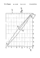
- FIG. 20 is a graph of the non-linearity of a microactuator that is determined using a process of the present invention.
- FIGS. 1, 2 , and 3 are perspective, top, and side views, respectively, of a spin-stand 100 of the present invention.
- Spin-stand 100 includes a disc 106 mounted on a spindle 102 , which is rotated by spindle motor 104 .
- Spindle motor 104 rests on a platform 108 that moves between two guide rails 110 and 112 .
- platform 108 is supported by a cushion of air during movement and is stabilized in a particular position by the application of a vacuum between platform 108 and a granite face 114 directly below platform 108 .
- movement of platform 108 along guides 110 and 112 is considered to be in the “X” direction as shown by arrows 115 of FIG. 2.
- a position encoder 121 is located along guide 110 to provide an indication of the position of platform 108 .
- Spin-stand 100 also includes a carriage 116 that moves between rails 118 and 120 in the Y direction shown by arrows 117 .
- carriage 116 is supported by a cushion of air during movement and is locked into position by applying a vacuum between carriage 116 and granite base 114 .
- a position encoder 123 is located along guide 120 to provide an indication of the position of platform 116 .
- carriage 116 and platform 108 both move sing electromotive motors mounted between one of the guide rails and the respective platform or carriage.
- Other types of motors such as a stepper motor for example, may be used in place of the electromotive motors.
- Carriage 116 supports a printed circuit board 130 and a support platform 124 .
- Support platform 124 includes a pair of support brackets 132 , 134 that are connected by respective pivot pins 136 and 138 to a pair of support brackets 131 , 133 on a pivoting platform 126 .
- support platform 124 supports pivoting platform 126 so that it may pivot about pivot pins 136 and 138 .
- Support platform 124 also supports a pivot motor 128 , which has an eccentric cam 129 that is in contact with a lever arm 127 on pivoting platform 126 .
- Pivoting platform 126 supports a mounting platform 139 that provides a base for a piezo platform 140 .
- Piezo platform 140 is connected to a suspension chuck 142 that holds a disc drive suspension 144 as shown in more detail below.
- Piezo platform 140 is connected to suspension chuck 142 through piezo elements that are able to move suspension chuck 142 in the “X” direction as shown by arrows 115 .
- the piezo elements of piezo platform 140 are able to move suspension chuck 142 by distances of less than 10 nanometers in response to electrical signals received from a control circuit.
- pivot motor 128 rotates eccentric cam 129 causing lever arm 127 and the back end of pivoting platform 126 to rotate upward about pivot pins 138 and 136 .
- Suspension chuck 142 which carries suspension 144 , is then placed on piezo platform 140 and spindle motor 104 is activated so that disc 106 rotates at a desired speed.
- carriage 116 is moved forward so that a head at the end of suspension 144 moves under disc 106 .
- Support platform 108 is also moved so that the head is positioned at a desired radius along disc 106 .
- motor 128 rotates eccentric cam 129 back so that pivoting platform 126 returns to its level position and the head is brought into proximity with disc 106 .
- the head on suspension 144 then flies over the surface of disc 106 .
- Test box 148 controls the types of tests performed on the head.
- test box 148 designates the location for the test track, the data to be written to the disc, and the position of the read head within the written track during read back of the test data.
- the read head can be moved to a number of different locations within a track during read back, so that the profile of the read head can be determined.
- FIG. 4 provides a more detailed perspective view of suspension chuck 142 and suspension 144 .
- Suspension 144 includes a gimble 154 that is connected to a slider 150 containing one or more heads 151 on a trailing edge 152 .
- Suspension 144 also includes a flexure arm 156 and a base plate 158 .
- Base plate 158 includes a boss 160 that extends into suspension chuck 142 through a hole 162 .
- Hole 162 is in communication with a channel 164 and a second channel 166 .
- Channel 164 extends to the end of suspension chuck 142 and channel 166 extends to spreader hole 168 .
- By inserting a pin in spreader hole 168 hole 162 can be widened so that boss 160 can be inserted into the hole. When the pin is removed from hole 168 , hole 162 becomes smaller causing suspension chuck 142 to grasp boss 160 .
- FIG. 5 provides a top view of suspension 144 .
- flexure arm 156 includes two microactuators 170 and 172 .
- microactuators 170 and 172 are capable of contracting or expanding depending on a voltage applied by respective conducting lines 174 , 176 and 178 , 180 .
- microactuator 170 is contracted while microactuator 172 is expanded so that the end of suspension 144 moves in a direction 181 .
- microactuator 172 is contracted while microactuator 170 is expanded to move the end of suspension 144 in a direction 182 .
- the movement of the microactuators can be controlled by a circuit either in circuit board 130 or in test box 148 of FIGS. 1, 2 and 3 .
- microactuators may be present in many different configurations along suspension 144 .
- microactuators may exist between flexure arm 156 and gimble 154 , along slider 150 and between slider 150 and head 152 .
- multiple microactuators may be used within the same suspension assembly with their movement coordinated by a circuit on circuit board 130 or in test box 148 .
- test tracks of the prior art do not include servo regions.
- An example of a disc with a test track of the prior art is shown in FIG. 6 where disc 200 includes a written track 202 that does not include servo regions. Instead, written track 202 includes only test data.
- the test track includes servo regions written onto the disc at various circumferential locations.
- An example of such a disc 204 is shown in FIG. 7, and includes a circumferential track 206 having data areas such as data areas 208 , 210 , and 212 that are interspersed with servo areas such as servo areas 213 , 214 , 216 and 218 .
- FIG. 8 shows a more detailed view of one embodiment of track 206 of FIG. 7, showing servo areas 213 , 214 , 216 , and 218 and test data areas 208 , 210 , and 212 .
- the cross track or radial direction is shown vertically and the down track direction or time is shown horizontally.
- Each servo region consists of an “A” burst and a “B” burst such as “A” burst 222 and “B” burst 224 of servo region 214 .
- “A” burst 222 and “B” burst 224 are radially offset from each other such that they share a common border along track center 226 of the test track.
- the test data written in test data regions 208 , 210 , and 212 is preferably written so that it is centered on track center line 226 .
- the read and write channels do not have to be concerned with handling both test data and servo data.
- the read and write channel must accommodate both servo data and test data.
- the present invention utilizes two gating signals.
- the first gating signal is a servo gating signal 250 shown in FIG. 9, which is high during servo regions 213 , 214 , 216 and 218 and is low at all other times.
- the second gating signal is a read/write gating signal 252 shown in FIG. 10, which is high during test data regions 208 , 210 , and 212 and is low at all other times.
- FIGS. 9 and 10 are aligned with FIG. 8 to show the alignment between the gating signals and the position of the read/write head during those gating signals.
- servo gating signal 250 and read/ write gating signal 252 are generated based on a once-around index read from the spindle of the spin-stand.
- a position encoder located on the spindle indicates the index's position. Because of limitations of the position encoder, the timing between the index signal and the actual index position can vary ⁇ 100 nsec. To accommodate this jitter, the transitions of servo gating signal 250 and read/write gating signal 252 are not aligned with each other. Instead, a small period of time passes between when read/write gating signal 252 has a transition and when servo gating signal 250 has a transition. This time period provides a tolerance to the index jitter and helps to ensure that test data does not write over servo data on the disc.
- FIG. 11 shows a more detailed layout of a servo region 300 for an embodiment of the present invention.
- Servo region 300 includes “A” burst region 302 and “B” burst region 304 .
- “A” burst region 302 includes two radially offset bursts 306 and 308 , where each burst includes a series of magnetic moment transitions that occur at a fixed frequency.
- dark shaded areas in bursts 306 and 308 indicate areas that have magnet moments that point to the right side of the page and white areas in bursts 306 and 308 indicate areas with magnetic moments that point to the left side of the page.
- Bursts 306 and 308 are radially separated from each other by a track width, which in one embodiment is the width of the read/write head being tested. In addition, each burst has a radial width equal to the track width. Although such widths are preferred, those skilled in the art will recognize that bursts 306 and 308 can have different widths and can be separated by different distances.
- “B” burst region 304 includes three bursts 310 , 312 , and 314 that each have a series of magnetic transitions which occur at a fixed frequency. Each of the “B” bursts has the same width and is radially separated from each other “B” burst by a distance equal to the track width.
- the bursts of “A” burst region 302 are radially offset from the bursts of “B” burst region 304 such that “A” burst 306 and “B” burst 312 each have an edge running along a track center line 316 , but “A” burst 306 is radially inside track center line 316 and “B” burst 312 is radially outside track center line 316 .
- “A” burst region 302 and “B” burst region 304 are separated circumferentially by an isolation area 318 and two tolerance regions 320 and 322 .
- Isolation area 318 is the normal separation distance between burst regions found in most servo systems in most disc drives.
- Tolerance areas 320 and 322 are added under the present invention because of the variations introduced into the servo tracking system due to the jitter of the index hardware. In particular, the spindle encoder introduces timing variations that may cause burst regions to overwrite each other unless tolerances such as tolerance areas 320 and 322 are written into the servo areas.
- FIG. 12 shows a layout for a servo region 330 representing a second embodiment of a servo region of the present invention.
- “A” burst region 332 and “B” burst region 334 provide a normal contribution to the servo signal and “C” burst region 336 and “D” burst region 338 provide a quadrature portion of the servo signal.
- the servo bursts of “C” burst region 336 are radially offset by one-half of a track width from the bursts of “B” burst region 334 so that servo burst 340 of “C” burst region 336 is centered on track center line 366 .
- Servo region 300 includes isolation regions 342 , 344 and 346 and tolerance areas 348 , 352 , 354 , 356 , 358 , 360 , 362 , and 364 , which are similar to the isolation regions and tolerance areas described above for FIG. 11 .
- a single position error signal is generated to identify the offset of the head with respect to the center of the track.
- a and B are the amplitude estimates of the read signal generated from the “A” and “B” burst regions respectively.
- the normalization of the difference of the two amplitudes by the sum of the two amplitudes is preferable, but not necessary.
- Methods of demodulating servo patterns to obtain their amplitude estimates are well known. For example, U.S. Pat. No. 4,530,019 entitled “SERVO PATTERNS” contains a description of one such implementation.
- C and D are the amplitude estimates of the read signal generated from the “C” and “D” burst regions respectively.
- This position error signal is known as a quadrature position error signal, while the position error signal of Equation 1 is referred to as the normal position error signal.
- Methods of combining these two position error signal estimates are well known. In one simple method, the servo system commutates between the two position error signal estimates to stay in the most linear region of each while moving in the cross track direction.
- timing signals that indicate when to look for the respective bursts.
- These timing signals are formed by test electronics under the present invention, which use the spindle index as a reference. As discussed above, this spindle index can jitter by as much as ⁇ 100 nsec from revolution to revolution. Therefore, to ensure that the entire burst is demodulated, the timing signals generated by the test electronics are generally made long enough so that if the timing signal were centered on a burst, the high portion of the timing signal would encompass the tolerance areas before and after the burst. For example, a timing signal for demodulating “A” burst 308 of FIG. 11 would be long enough to encompass tolerance area 324 , “A” burst 308 , and tolerance area 320 .
- Amplitude estimates of the respective bursts can be formed in several different ways. Under one embodiment of the present invention, asynchronous methods of detection are used, such as peak detection with a qualifier threshold, or root-mean square detection to provide an average estimate of the signal. These types of circuits are standard and well known.
- FIG. 13 provides a flow diagram for initializing the spin-stand for testing under one embodiment of the present invention.
- the width of the read head is determined so that it can be used to define the track pitch at which data will be written to the disc.
- this embodiment of the invention produces a more linear position error signal.
- this width matching helps to prevent the position error signal from having regions of non-zero gain, which make position estimation difficult.
- the reader width can be determined using a number of different methods. In one embodiment, a broad track is written to the disc and then the read head is moved radially across the full track. By measuring the change in the amplitude of the read signal as the read head is moved radially across the track, the width of the read head can be determined. Such a full track scan can be implemented using the piezo element of the spin-stand and does not require the activation of any of the microactuators on the suspension.
- a very thin track can be written to the disc and a microtrack profile can be taken to estimate the electrical reader width.
- a microtrack profile is generated by radially moving the read head across the track and recording where the read head generates a read signal.
- the initialization process continues at step 402 where a servo pattern is written to the disc.
- the servo pattern is generated by moving a write head to a test radius, offsetting the head by one-half of the reader width, and writing a series of “A” bursts at selected locations around the disc.
- the write head is then radially offset away from the spindle by an additional reader width and “B” bursts are written circumferentially around the disc at designated servo areas.
- the circumferential location of the “A” and “B” bursts around the disc is controlled in part by the index on the spindle read by the test circuitry.
- a second set of “B” bursts is then written to the disc by moving the write head so that it is offset from the track centerline toward the spindle by one-half of a reader width.
- a second set of “A” bursts can be written by moving the write head an additional reader width toward the spindle.
- the two sets of “A” and “B” bursts described above should be sufficient to perform track following. However, for extremely narrow track widths, additional sets of bursts may be needed. It is noted that as a general rule, one set of bursts should be written beyond the furthest expected extent of motion of the head so that the last servo null has a trimmed track on the outer side of the pattern.
- step 404 the servo regions are profiled to generate a table that relates position error signals to actual positions over the disc.
- this step is accomplished using the fine positioning mechanism of the spin-stand.
- a controller in test box 148 or circuit board 130 generates a series of position values that represents desired positions for the head. Based on these values, piezo element 140 steps the head radially through the servo bursts. At each step, the position value and the value of the position error signal are stored in a table.
- FIG. 14 provides a graph 450 based on such a table that relates normal position error signal values, shown on vertical axis 452 , to actual positions, shown on horizontal axis 454 .
- FIG. 14 also shows a graph 456 that relates quadrature position error signal values to cross track positions.
- the step size for creating the table is chosen so that there is adequate resolution of the position error signal.
- the servo burst regions are sampled over a radial distance that is larger than the expected range of motion of the head. This will ensure that the table contains values for all possible positions of the head.
- a null-type servo pattern is used instead of the split-burst servo patterns of FIGS. 11 and 12.
- An example of a null-type servo pattern that may be used in the present invention is shown as pattern 460 of FIG. 15 .
- the radial dimension of the disc is shown vertically, and the angular dimension of the disc is shown horizontally, with arrow 462 indicating the down-track direction and arrow 464 indicating a cross-track or radial direction.
- the shaded regions in FIG. 15 correspond to regions of opposite magnetic polarity as compared to the non-shaded regions. For example, in a longitudinal recording system, if the longitudinal magnetization in the non-shaded regions were right-to-left in the figure, then the longitudinal magnetization in the shaded regions would be left-to-right. Within these regions, the magnetic medium is saturated in either longitudinal direction, as is standard practice in digital magnetic recording.
- Servo sector 460 includes leading field 476 , “sync” or “phase” field 478 , middle field 480 , normal position error field 482 , quadrature position error field 484 and trailing field 486 .
- Leading field 476 , middle fields 480 and trailing field 486 may be “empty” as shown in FIG. 15 or may include additional servo data.
- leading field 476 includes an index mark.
- Phase field 478 contains radially coherent magnetic transitions. As head 474 passes over phase field 478 , the magnetization pattern within phase field 478 induces an oscillating signal in the output of head 474 .
- Normal position error field 482 and quadrature position error field 484 contain null-type magnetic patterns.
- the quadrature magnetic pattern of quadrature position error field 484 is offset by one-half of a track width with respect to the normal magnetic pattern of normal position error field 482 .
- the quadrature magnetic pattern is split in half by placing half of the quadrature pattern before the normal pattern and half of the quadrature pattern after the normal pattern.
- Phase field 478 and the position error fields are typically written with reference to a separate clock track.
- the clock track is written by a separate clock head that is typically supported on a separate stage from the read head under test.
- the clock track is not written on the same disc surface as the phase field and the position error fields but instead is written on a different surface on the same disc or on a separate disc. In systems that use a separate disc, both discs share a common spindle.
- microactuator tests include a hysteresis measurement, a frequency response measurement, and a non-linearity measurement. Each of these tests is described below.
- a hysteresis measurement indicates the degree to which a microactuator's movement is dependent on its past position.
- FIG. 16 provides a flow diagram for performing such a hysteresis measurement.
- the head is first positioned at a track center at step 600 . This positioning is done entirely by the spin-stand piezo element, such that no voltage or current is applied to the microactuators to be tested.
- the input to a single microactuator is stepped up. Depending on the microactuator, this can involve either stepping up the voltage and/or the current to the microactuator.
- the stepped-up input to the microactuator causes the microactuator to move the head.
- the read head At its new position, the read head generates a read signal that is demodulated to identify a position error value. This value is then applied to the position look-up table at step 604 to determine the position of the head.
- the head's position and the amount of input applied to the microactuator to cause the head to reach that position are then stored in a table for latter use.
- the method determines if it has reached the maximum positive input for the microactuator. If it has not reached the maximum input, the process returns to step 602 were the input is stepped up once again.
- step 606 When the maximum positive input is reached at step 606 , the process continues at step 608 where the input to the microactuator is stepped down by an amount equal to the step sizes used in step 602 . The position of the head is then measured at step 610 and the value of the input to the microactuator and the position of the head are stored for later use. At step 612 , the method determines if it has reached the maximum negative input for the microactuator. If it has not reached the maximum negative input, the process returns to step 608 .
- step 612 the process continues at step 614 where the input to the microactuator is once again stepped up. The position of the head is then measured and recorded at step 616 along with the input to the microactuator.
- step 618 the method determines if it has once again reached the maximum positive input for the microactuator. If is has not reached the maximum positive input, the method returns to step 614 . When the method reaches the maximum positive input at step 618 , the process ends at step 620 .
- FIG. 16 produces a sequence of input values and head positions.
- a graph 640 of the position values and their respective input values is shown in FIG. 17 .
- the applied input to the microactuator is shown along horizontal axis 642 and the resulting position of the head is shown along vertical axis 644 .
- Graph 640 begins from point 646 where no input has been applied to the microactuator and the head is positioned over the track center. The graph then extends down to the right to a point 648 where the maximum positive input has been applied to the microactuator. The graph then returns up to the left to a point 650 representing the maximum negative input applied to the microactuator. Note that as the applied input to the microactuator returns to zero at point 652 , the head is not at track center but is deflected due to the hysteresis of the microactuator.
- Another embodiment of the present invention measures the frequency response of a microactuator.
- this test is performed by applying a sinusoidal input to the microacutator.
- the sinusoidal input is referenced to the spindle index so that the phase of the frequency response can be determined as well as the magnitude of the frequency response.
- the same frequency reference is used for the sinusoidal microactuator input and the spindle speed regulator. If this is not the case, the phase between the spindle and the input signal can drift.
- FIG. 18 provides a block diagram for a test apparatus used in performing a frequency response measurement of a microactuator.
- a sinusoidal reference signal 650 is provided to a microactuator 652 .
- microactuator 652 moves head 654 .
- head 654 reads servo information from the disc and thereby generates a servo read signal.
- the servo read signal is provided to a demodulator 658 , which demodulates the signal to produce a position error signal 660 as described above.
- Position error signal 660 is provided to PES-to-position converter 662 as a search value for searching a position error signal-to-position look-up table 664 . Based on this search, converter 662 generates a position value signal 666 that is input to a filter transform module 668 .
- Filter transform module 668 also receives microactuator input 650 .
- Filter transform module 668 filters and transforms the microactuator input signal and the position value signal to identify a magnitude and phase for a frequency component of each signal.
- the selected frequency component is the primary frequency of input signal 650 .
- the filtering and transform functions of module 668 can be achieved by performing a single point Fourier transform at the desired frequency or by performing a fast Fourier transform across a spectrum of frequencies and selecting the magnitude and phase of a desired frequency.
- the magnitude and phase identified for position signal 666 are provided on outputs 670 and 671 to a compare module 674 .
- the magnitude and phase associated with microactuator input 650 are provided on outputs 672 and 673 to compare module 674 .
- Compare module 674 compares the magnitudes of the frequency component in the two respective signals to identify the gain of the microactuator at the selected frequency. Compare module 674 can also compare the phases of the frequency component in the two signals to identify a phase shift associated with microactuator 652 . The gain of the microactuator and the phase shift of the microactuator are then output along outputs 676 and 677 .
- FIG. 19 shows a graph 700 of the magnitude frequency response for a microactuator that was produced using the process described above.
- frequency in units of 5 kHz is shown along horizontal axis 702 and magnitude in decibels is shown along vertical axis 704 .
- the frequency response measurement described above is augmented in another embodiment of the present invention by determining the frequency response of the microactuator using different input signal amplitudes.
- a microactuator has a linear response to changes in the amplitude of the input signal.
- the distance that the head moves across a track with each oscillation of the input signal should be a linear function of the amplitude of the input signal.
- Actual microactuators do not behave linearly.
- the measured change in the frequency response can be compared to a specification to determine if the microactuator is fit enough to be placed in a disc drive.
- FIG. 20 provides graphs of three frequency responses for a microactuator driven by three different voltages. Specifically, graphs 800 , 802 , and 804 show how far the microactuator moves for applied voltages of 0.5, 2.5 and 5 volts respectively. In FIG. 20, frequency is shown along horizontal axis 806 and the distance the microactuator moves is shown in units of nanometers per applied volt along vertical axis 808 . From FIG. 20, it can be seen that as the applied voltage increases, the peak of FIG. 20 shifts to a higher frequency and the magnitude increases.
- the present invention provides a method of testing a microactuator that is part of a suspension assembly for a disc drive before placing the suspension assembly in a disc drive.
- the method includes steps of positioning head 654 over a disc based in part on servo information 656 read from the disc. At least one input signal 650 is applied to at least one microactuator 652 on the suspension assembly 144 . Servo information 656 is then read from the disc to determine a position 666 of the head 654 . The position 666 of head 654 is compared to the applied input signal 650 to determine a performance characteristic of the microactuator 652 .
- the measured performance characteristic is a hysteresis of microactuator 652 . In other embodiments, the measured performance characteristic is the frequency response of microactuator 652 .
- An apparatus 100 for testing a microactuator that forms part of a suspension assembly includes a disc 106 that is separate from the disc drive and capable of spinning. Apparatus 100 also includes a positioning system 108 , 140 , 142 , 116 capable of positioning the head relative to a track on the disc.
- a microactuator control 130 , 148 is provided that generates at least one input signal to at least one microactuator 170 , 172 .
- a position measurement system 130 , 148 is capable of determining the position of the head over the track and a microactuator test controller 130 , 148 that is capable of determining a microactuator performance characteristic based on the input signal to the microactuator 170 , 172 and the position of the head.
Abstract
Description


Claims (17)
Priority Applications (1)
| Application Number | Priority Date | Filing Date | Title |
|---|---|---|---|
| US09/426,349 US6510752B1 (en) | 1999-02-22 | 1999-10-25 | Method and apparatus for testing microactuators on a suspension assembly |
Applications Claiming Priority (2)
| Application Number | Priority Date | Filing Date | Title |
|---|---|---|---|
| US12114699P | 1999-02-22 | 1999-02-22 | |
| US09/426,349 US6510752B1 (en) | 1999-02-22 | 1999-10-25 | Method and apparatus for testing microactuators on a suspension assembly |
Publications (1)
| Publication Number | Publication Date |
|---|---|
| US6510752B1 true US6510752B1 (en) | 2003-01-28 |
Family
ID=26819132
Family Applications (1)
| Application Number | Title | Priority Date | Filing Date |
|---|---|---|---|
| US09/426,349 Expired - Fee Related US6510752B1 (en) | 1999-02-22 | 1999-10-25 | Method and apparatus for testing microactuators on a suspension assembly |
Country Status (1)
| Country | Link |
|---|---|
| US (1) | US6510752B1 (en) |
Cited By (30)
| Publication number | Priority date | Publication date | Assignee | Title |
|---|---|---|---|---|
| US20030002198A1 (en) * | 2001-07-02 | 2003-01-02 | Subrahamanyan Pradeep K. | High bandwidth large stroke spin-stand for data storage component testing |
| US20050046659A1 (en) * | 1999-06-30 | 2005-03-03 | Kia Silverbrook | Method of detecting a fault condition in a micro-electromechanical device |
| US20060023341A1 (en) * | 2004-07-29 | 2006-02-02 | Vinod Sharma | Method and apparatus for micro-actuator stroke sensitivity calibration in a hard disk drive |
| US7064914B1 (en) | 2004-12-22 | 2006-06-20 | Seagate Technology Llc | Position error signal quality |
| US7131346B1 (en) | 2004-10-15 | 2006-11-07 | Western Digital (Fremont), Inc. | Spin stand testing system with fine positioner for head stack assembly |
| US7154689B1 (en) * | 2004-02-05 | 2006-12-26 | Maxtor Corporation | Apparatus for writing servo bursts on a disk with servo track pitch based on read element width and methods of manufacturing same |
| US20070223136A1 (en) * | 2006-03-23 | 2007-09-27 | Seagate Technology, Llc | Micro actuator gain calibration based on a sinusoidal input signal |
| US8094414B1 (en) | 2009-07-09 | 2012-01-10 | Western Digital Technologies, Inc. | Head gimbal assembly mounting mechanism |
| US8098460B1 (en) | 2009-06-30 | 2012-01-17 | Western Digital Technologies, Inc. | Dual-state clamping mechanism |
| US8218256B1 (en) | 2009-10-30 | 2012-07-10 | Western Digital Technologies, Inc. | Disk spindle assembly cartridge |
| US20120200287A1 (en) * | 2009-10-22 | 2012-08-09 | Xyratex Technology Limited | Spinstands for testing a head gimbal assembly |
| US8270118B1 (en) | 2009-10-30 | 2012-09-18 | Western Digital Technologies, Inc. | Head stack assembly cartridge |
| US8322235B1 (en) | 2011-02-18 | 2012-12-04 | Western Digital Technologies, Inc. | Microactuator test assembly comprising a spreader pin for engaging a load beam of an actuator arm |
| US8335049B1 (en) | 2010-06-07 | 2012-12-18 | Western Digital Technologies, Inc. | Disk drive detecting crack in microactuator |
| US8339747B1 (en) | 2011-03-11 | 2012-12-25 | Western Digital Technologies, Inc. | Removable actuator assemblies for testing head gimbal assemblies of a storage device |
| US8432630B1 (en) | 2010-06-30 | 2013-04-30 | Western Digital Technologies, Inc. | Disk drive component test system |
| US8483027B1 (en) | 2011-05-25 | 2013-07-09 | Western Digital Technologies, Inc. | Disk drive qualifying head/disk interface using jitter seek excitation |
| US8499652B1 (en) | 2010-04-21 | 2013-08-06 | Western Digital Technologies, Inc. | Test ramp for testing microactuators used in a multi-head disk drive |
| US8547657B1 (en) | 2010-06-10 | 2013-10-01 | Western Digital Technologies, Inc. | Disk drive detecting defective microactuator |
| US8605383B1 (en) | 2012-05-21 | 2013-12-10 | Western Digital Technologies, Inc. | Methods, devices and systems for characterizing polarities of piezoelectric (PZT) elements of a two PZT element microactuator |
| US8611040B1 (en) | 2012-09-27 | 2013-12-17 | Western Digital Technologies, Inc. | Disk drive adjusting microactuator gain by injecting a sinusoid into a servo control system |
| US8705209B2 (en) | 2011-10-14 | 2014-04-22 | Western Digital Technologies, Inc. | Suspension clamp for clamping a disk drive suspension to an actuator arm |
| US8724254B1 (en) | 2011-05-10 | 2014-05-13 | Western Digital Technologies, Inc. | Evaluating dual stage actuator response in a disk drive by adding sinusoid to control signal |
| US8780489B1 (en) | 2012-11-20 | 2014-07-15 | Western Digital Technologies, Inc. | Disk drive estimating microactuator gain by injecting a sinusoid into a closed loop servo system |
| US8797664B1 (en) | 2012-12-22 | 2014-08-05 | Western Digital Technologies, Inc. | Polarity detection of piezoelectric actuator in disk drive |
| US8902538B1 (en) | 2013-03-29 | 2014-12-02 | Western Digital Technologies, Inc. | Disk drive detecting crack in microactuator |
| US9122625B1 (en) | 2012-12-18 | 2015-09-01 | Western Digital Technologies, Inc. | Error correcting code encoder supporting multiple code rates and throughput speeds for data storage systems |
| US9142235B1 (en) | 2009-10-27 | 2015-09-22 | Western Digital Technologies, Inc. | Disk drive characterizing microactuator by injecting sinusoidal disturbance and evaluating feed-forward compensation values |
| US9153283B1 (en) | 2014-09-30 | 2015-10-06 | Western Digital Technologies, Inc. | Data storage device compensating for hysteretic response of microactuator |
| US10418055B1 (en) * | 2018-04-26 | 2019-09-17 | Seagate Technology Llc | Dual-stage head suspension assembly having additional microactuator pair |
Citations (19)
| Publication number | Priority date | Publication date | Assignee | Title |
|---|---|---|---|---|
| US4530019A (en) * | 1984-06-04 | 1985-07-16 | Dma Systems | Servo pattern |
| US4811144A (en) | 1987-12-03 | 1989-03-07 | Cecil & Hume Associates, Inc. | Magnetic recording head motion translation apparatus for head/media evaluation systems |
| US4902971A (en) | 1988-09-14 | 1990-02-20 | Guzik Technical Enterprises, Inc. | Magnetic head and disc tester employing pivot arm on linearly movable slide |
| US5189578A (en) * | 1989-06-28 | 1993-02-23 | Hitachi, Ltd. | Disk system with sub-actuators for fine head displacement |
| US5254946A (en) | 1992-02-25 | 1993-10-19 | Guzik Technical Enterprises, Inc. | Magnetic head and disk tester with head centrally mounted on radially-moving, rotatable platform that surrounds disk |
| US5382887A (en) | 1993-03-25 | 1995-01-17 | Guzik Technical Enterprises, Inc. | Method and apparatus for compensating positioning error in magnetic-head and magnetic-disk tester |
| US5402400A (en) * | 1992-09-04 | 1995-03-28 | Hitachi, Ltd. | Method and apparatus for eliminating external disturbances in a disk drive device |
| US5465183A (en) * | 1993-01-07 | 1995-11-07 | Nec Corporation | Control system for positioning head in disk device by estimating and correcting actuator parameters based on head position and actuator drive current obtained by vibrating the head |
| US5621178A (en) * | 1994-10-03 | 1997-04-15 | U.S. Philips Corporation | Piezoelectric sensor system |
| US5654841A (en) * | 1995-07-07 | 1997-08-05 | Seagate Technology, Inc. | Detection of mechanical defects in a disc drive using injected test signals |
| US5793571A (en) | 1995-06-01 | 1998-08-11 | Hutchinson Technology Incorporated | Method for manufacturing a head suspension with a microactuator |
| US5801531A (en) | 1996-01-18 | 1998-09-01 | Read-Rite Corporation | Apparatus and method for testing magnetic heads using translational slides and a rotatable arm |
| US5805375A (en) * | 1994-08-01 | 1998-09-08 | International Business Machines Corporation | Wobble motor microactuator for fine positioning and disk drive incorporating the microactuator |
| US5862015A (en) * | 1996-05-23 | 1999-01-19 | Hutchinson Technology Incorporated | Head suspension with resonance feedback transducer |
| US5872674A (en) * | 1996-11-22 | 1999-02-16 | Seagate Technology, Inc. | Actuator bias prediction using lookup-table hysteresis modeling |
| US5946158A (en) * | 1997-07-11 | 1999-08-31 | Western Digital Corporation | Self-PES linearity calibration method for MR head |
| US5998994A (en) * | 1997-01-31 | 1999-12-07 | Hitachi Electronics Engineering Co., Ltd. | MR head offset correction method and magnetic disk certifier |
| US6078476A (en) * | 1997-12-17 | 2000-06-20 | Texas Instruments Incorporated | Twin head design for micro-actuator position sensing in a hard disk drive |
| US6088181A (en) * | 1996-05-30 | 2000-07-11 | Kabushiki Kaisha Toshiba | Magnetic recording/reproducing device using composite head |
-
1999
- 1999-10-25 US US09/426,349 patent/US6510752B1/en not_active Expired - Fee Related
Patent Citations (19)
| Publication number | Priority date | Publication date | Assignee | Title |
|---|---|---|---|---|
| US4530019A (en) * | 1984-06-04 | 1985-07-16 | Dma Systems | Servo pattern |
| US4811144A (en) | 1987-12-03 | 1989-03-07 | Cecil & Hume Associates, Inc. | Magnetic recording head motion translation apparatus for head/media evaluation systems |
| US4902971A (en) | 1988-09-14 | 1990-02-20 | Guzik Technical Enterprises, Inc. | Magnetic head and disc tester employing pivot arm on linearly movable slide |
| US5189578A (en) * | 1989-06-28 | 1993-02-23 | Hitachi, Ltd. | Disk system with sub-actuators for fine head displacement |
| US5254946A (en) | 1992-02-25 | 1993-10-19 | Guzik Technical Enterprises, Inc. | Magnetic head and disk tester with head centrally mounted on radially-moving, rotatable platform that surrounds disk |
| US5402400A (en) * | 1992-09-04 | 1995-03-28 | Hitachi, Ltd. | Method and apparatus for eliminating external disturbances in a disk drive device |
| US5465183A (en) * | 1993-01-07 | 1995-11-07 | Nec Corporation | Control system for positioning head in disk device by estimating and correcting actuator parameters based on head position and actuator drive current obtained by vibrating the head |
| US5382887A (en) | 1993-03-25 | 1995-01-17 | Guzik Technical Enterprises, Inc. | Method and apparatus for compensating positioning error in magnetic-head and magnetic-disk tester |
| US5805375A (en) * | 1994-08-01 | 1998-09-08 | International Business Machines Corporation | Wobble motor microactuator for fine positioning and disk drive incorporating the microactuator |
| US5621178A (en) * | 1994-10-03 | 1997-04-15 | U.S. Philips Corporation | Piezoelectric sensor system |
| US5793571A (en) | 1995-06-01 | 1998-08-11 | Hutchinson Technology Incorporated | Method for manufacturing a head suspension with a microactuator |
| US5654841A (en) * | 1995-07-07 | 1997-08-05 | Seagate Technology, Inc. | Detection of mechanical defects in a disc drive using injected test signals |
| US5801531A (en) | 1996-01-18 | 1998-09-01 | Read-Rite Corporation | Apparatus and method for testing magnetic heads using translational slides and a rotatable arm |
| US5862015A (en) * | 1996-05-23 | 1999-01-19 | Hutchinson Technology Incorporated | Head suspension with resonance feedback transducer |
| US6088181A (en) * | 1996-05-30 | 2000-07-11 | Kabushiki Kaisha Toshiba | Magnetic recording/reproducing device using composite head |
| US5872674A (en) * | 1996-11-22 | 1999-02-16 | Seagate Technology, Inc. | Actuator bias prediction using lookup-table hysteresis modeling |
| US5998994A (en) * | 1997-01-31 | 1999-12-07 | Hitachi Electronics Engineering Co., Ltd. | MR head offset correction method and magnetic disk certifier |
| US5946158A (en) * | 1997-07-11 | 1999-08-31 | Western Digital Corporation | Self-PES linearity calibration method for MR head |
| US6078476A (en) * | 1997-12-17 | 2000-06-20 | Texas Instruments Incorporated | Twin head design for micro-actuator position sensing in a hard disk drive |
Cited By (48)
| Publication number | Priority date | Publication date | Assignee | Title |
|---|---|---|---|---|
| US20050046659A1 (en) * | 1999-06-30 | 2005-03-03 | Kia Silverbrook | Method of detecting a fault condition in a micro-electromechanical device |
| US6969142B2 (en) * | 1999-06-30 | 2005-11-29 | Silverbrook Research, Pty Ltd | Method of detecting a fault condition in a micro-electromechanical device |
| US20050275492A1 (en) * | 1999-06-30 | 2005-12-15 | Silverbrook Research Pty Ltd | Mems fluid ejection device configured for detecting a fault condition |
| US8317301B2 (en) | 1999-06-30 | 2012-11-27 | Zamtec Limited | Printing nozzle arrangement having fault detector |
| US8038252B2 (en) | 1999-06-30 | 2011-10-18 | Silverbrook Research Pty Ltd | Method of detecting MEM device faults with single current pulse |
| US20100073429A1 (en) * | 1999-06-30 | 2010-03-25 | Silverbrook Research Pty Ltd | Inkjet Nozzle Device With Cantilevered Actuating Arm |
| US7635177B2 (en) | 1999-06-30 | 2009-12-22 | Silverbrook Research Pty Ltd | Inkjet nozzle device with cantilevered actuating arm |
| US20060130904A1 (en) * | 1999-06-30 | 2006-06-22 | Silverbrook Research Pty Ltd | Fluid ejection device with inner and outer arms |
| US7128093B2 (en) | 1999-06-30 | 2006-10-31 | Silverbrook Research Pty Ltd | MEMS fluid ejection device configured for detecting a fault condition |
| US7210666B2 (en) | 1999-06-30 | 2007-05-01 | Silverbrook Research Pty Ltd | Fluid ejection device with inner and outer arms |
| US20030002198A1 (en) * | 2001-07-02 | 2003-01-02 | Subrahamanyan Pradeep K. | High bandwidth large stroke spin-stand for data storage component testing |
| US7154699B2 (en) * | 2001-07-02 | 2006-12-26 | Seagate Technology Llc | High bandwidth large stroke spin-stand |
| US7154689B1 (en) * | 2004-02-05 | 2006-12-26 | Maxtor Corporation | Apparatus for writing servo bursts on a disk with servo track pitch based on read element width and methods of manufacturing same |
| US20060023341A1 (en) * | 2004-07-29 | 2006-02-02 | Vinod Sharma | Method and apparatus for micro-actuator stroke sensitivity calibration in a hard disk drive |
| US7009804B2 (en) * | 2004-07-29 | 2006-03-07 | Samsung Electronics Co., Ltd. | Method and apparatus for micro-actuator stroke sensitivity calibration in a hard disk drive |
| US7131346B1 (en) | 2004-10-15 | 2006-11-07 | Western Digital (Fremont), Inc. | Spin stand testing system with fine positioner for head stack assembly |
| US20060132949A1 (en) * | 2004-12-22 | 2006-06-22 | Seagate Technology Llc | Position error signal quality |
| US7064914B1 (en) | 2004-12-22 | 2006-06-20 | Seagate Technology Llc | Position error signal quality |
| US20070223136A1 (en) * | 2006-03-23 | 2007-09-27 | Seagate Technology, Llc | Micro actuator gain calibration based on a sinusoidal input signal |
| US7423837B2 (en) * | 2006-03-23 | 2008-09-09 | Seagate Technology Llc | Micro actuator gain calibration based on a sinusoidal input signal |
| US8098460B1 (en) | 2009-06-30 | 2012-01-17 | Western Digital Technologies, Inc. | Dual-state clamping mechanism |
| US8094414B1 (en) | 2009-07-09 | 2012-01-10 | Western Digital Technologies, Inc. | Head gimbal assembly mounting mechanism |
| US20120200287A1 (en) * | 2009-10-22 | 2012-08-09 | Xyratex Technology Limited | Spinstands for testing a head gimbal assembly |
| US8873200B2 (en) * | 2009-10-22 | 2014-10-28 | Xyratex Technology Limited | Spinstands for testing a head gimbal assembly |
| US9142235B1 (en) | 2009-10-27 | 2015-09-22 | Western Digital Technologies, Inc. | Disk drive characterizing microactuator by injecting sinusoidal disturbance and evaluating feed-forward compensation values |
| US8270118B1 (en) | 2009-10-30 | 2012-09-18 | Western Digital Technologies, Inc. | Head stack assembly cartridge |
| US8432631B1 (en) | 2009-10-30 | 2013-04-30 | Western Digital Technologies, Inc. | Disk spindle assembly cartridge |
| US8218256B1 (en) | 2009-10-30 | 2012-07-10 | Western Digital Technologies, Inc. | Disk spindle assembly cartridge |
| US8544164B1 (en) | 2009-10-30 | 2013-10-01 | Western Digital Technologies, Inc. | Method for test mounting a head stack assembly cartridge |
| US8499652B1 (en) | 2010-04-21 | 2013-08-06 | Western Digital Technologies, Inc. | Test ramp for testing microactuators used in a multi-head disk drive |
| US8335049B1 (en) | 2010-06-07 | 2012-12-18 | Western Digital Technologies, Inc. | Disk drive detecting crack in microactuator |
| US8547657B1 (en) | 2010-06-10 | 2013-10-01 | Western Digital Technologies, Inc. | Disk drive detecting defective microactuator |
| US8432630B1 (en) | 2010-06-30 | 2013-04-30 | Western Digital Technologies, Inc. | Disk drive component test system |
| US8322235B1 (en) | 2011-02-18 | 2012-12-04 | Western Digital Technologies, Inc. | Microactuator test assembly comprising a spreader pin for engaging a load beam of an actuator arm |
| US8339747B1 (en) | 2011-03-11 | 2012-12-25 | Western Digital Technologies, Inc. | Removable actuator assemblies for testing head gimbal assemblies of a storage device |
| US8724254B1 (en) | 2011-05-10 | 2014-05-13 | Western Digital Technologies, Inc. | Evaluating dual stage actuator response in a disk drive by adding sinusoid to control signal |
| US8483027B1 (en) | 2011-05-25 | 2013-07-09 | Western Digital Technologies, Inc. | Disk drive qualifying head/disk interface using jitter seek excitation |
| US8705209B2 (en) | 2011-10-14 | 2014-04-22 | Western Digital Technologies, Inc. | Suspension clamp for clamping a disk drive suspension to an actuator arm |
| US9196301B1 (en) | 2011-10-14 | 2015-11-24 | Western Digital Technologies, Inc. | Suspension clamp for clamping a disk drive suspension to an actuator arm |
| US8605383B1 (en) | 2012-05-21 | 2013-12-10 | Western Digital Technologies, Inc. | Methods, devices and systems for characterizing polarities of piezoelectric (PZT) elements of a two PZT element microactuator |
| US8611040B1 (en) | 2012-09-27 | 2013-12-17 | Western Digital Technologies, Inc. | Disk drive adjusting microactuator gain by injecting a sinusoid into a servo control system |
| US8780489B1 (en) | 2012-11-20 | 2014-07-15 | Western Digital Technologies, Inc. | Disk drive estimating microactuator gain by injecting a sinusoid into a closed loop servo system |
| US9122625B1 (en) | 2012-12-18 | 2015-09-01 | Western Digital Technologies, Inc. | Error correcting code encoder supporting multiple code rates and throughput speeds for data storage systems |
| US9495243B2 (en) | 2012-12-18 | 2016-11-15 | Western Digital Technologies, Inc. | Error correcting code encoder supporting multiple code rates and throughput speeds for data storage systems |
| US8797664B1 (en) | 2012-12-22 | 2014-08-05 | Western Digital Technologies, Inc. | Polarity detection of piezoelectric actuator in disk drive |
| US8902538B1 (en) | 2013-03-29 | 2014-12-02 | Western Digital Technologies, Inc. | Disk drive detecting crack in microactuator |
| US9153283B1 (en) | 2014-09-30 | 2015-10-06 | Western Digital Technologies, Inc. | Data storage device compensating for hysteretic response of microactuator |
| US10418055B1 (en) * | 2018-04-26 | 2019-09-17 | Seagate Technology Llc | Dual-stage head suspension assembly having additional microactuator pair |
Similar Documents
| Publication | Publication Date | Title |
|---|---|---|
| US6510752B1 (en) | Method and apparatus for testing microactuators on a suspension assembly | |
| US8786979B1 (en) | Self servo write process for discrete track media | |
| US6301071B2 (en) | Methods and systems for self-servowriting including maintaining a reference level within a usable dynamic range | |
| US6785084B2 (en) | Correction of dynamic track spacing errors in storage devices | |
| US6587293B1 (en) | Method for servo writing servo pattern at a desired speed | |
| US6704156B1 (en) | Self-writing of servo patterns in a disk drive using a printed reference pattern | |
| US6738205B1 (en) | Self-writing of servo patterns in disk drives | |
| US6215606B1 (en) | Method and system for determining the widest recording head of a recording device | |
| US6181505B1 (en) | Synchronous digital demodulator with integrated read and servo channels | |
| KR0165711B1 (en) | Radial self-propagation pattern generation for disk file servo-writing | |
| US6304407B1 (en) | Self-writing of servo patterns based on printed reference pattern in rotating disk drive | |
| US6608477B2 (en) | Apparatus and method for altering track scan data based on head width relative to data track width and determining the position error signal from the altered track scan data to qualify the head in a data storage device | |
| US6469849B1 (en) | Field ratioing demodulation circuit for a null-type servo pattern | |
| US6243224B1 (en) | Asynchronous digital demodulator and method for a null-type servo pattern | |
| US20070291401A1 (en) | Contact detection using calibrated seeks | |
| US6538838B1 (en) | Method and apparatus for closed-loop spin-stand testing | |
| US20060039250A1 (en) | Method for positioning a scanning probe on a target track of a multi-track storage medium, storage device, scanning device, and storage medium | |
| KR20010022948A (en) | Constant density servo information in a disc drive | |
| US7130146B2 (en) | Two-pass-per-track servo burst patterns | |
| US7889451B2 (en) | Magnetic recording apparatus and clock signal generating method | |
| US20010033450A1 (en) | Radially offset writer position control in a disc drive made with substantially identical heads | |
| Sacks | Position signal generation in magnetic disk drives | |
| KR0160320B1 (en) | Method and apparatus for servo positioning in a direct access storage device | |
| US7009802B1 (en) | Systems and methods for printed-media SSW reference pattern with extra servo bursts used near OD | |
| US20050157417A1 (en) | Variable frequency chevron in printed media reference pattern to improve servo demodulation |
Legal Events
| Date | Code | Title | Description |
|---|---|---|---|
| AS | Assignment |
Owner name: SEAGATE TECHNOLOGY, INC., CALIFORNIA Free format text: ASSIGNMENT OF ASSIGNORS INTEREST;ASSIGNORS:SACKS, ALEXEI H.;MCGLENNEN, JAMES H.;VAN DER SCHANS, ALBERT;REEL/FRAME:010345/0782 Effective date: 19991018 |
|
| AS | Assignment |
Owner name: SEAGATE TECHNOLOGY LLC, CALIFORNIA Free format text: ASSIGNMENT OF ASSIGNORS INTEREST;ASSIGNOR:SEAGATE TECHNOLOGY, INC.;REEL/FRAME:010988/0347 Effective date: 20000628 |
|
| AS | Assignment |
Owner name: JPMORGAN CHASE BANK, AS COLLATERAL AGENT, NEW YORK Free format text: SECURITY AGREEMENT;ASSIGNOR:SEAGATE TECHNOLOGY LLC;REEL/FRAME:013177/0001 Effective date: 20020513 Owner name: JPMORGAN CHASE BANK, AS COLLATERAL AGENT,NEW YORK Free format text: SECURITY AGREEMENT;ASSIGNOR:SEAGATE TECHNOLOGY LLC;REEL/FRAME:013177/0001 Effective date: 20020513 |
|
| AS | Assignment |
Owner name: SEAGATE TECHNOLOGY LLC, CALIFORNIA Free format text: RELEASE OF SECURITY INTERESTS IN PATENT RIGHTS;ASSIGNOR:JPMORGAN CHASE BANK, N.A. (FORMERLY KNOWN AS THE CHASE MANHATTAN BANK AND JPMORGAN CHASE BANK), AS ADMINISTRATIVE AGENT;REEL/FRAME:016958/0340 Effective date: 20051130 |
|
| REMI | Maintenance fee reminder mailed | ||
| LAPS | Lapse for failure to pay maintenance fees | ||
| STCH | Information on status: patent discontinuation |
Free format text: PATENT EXPIRED DUE TO NONPAYMENT OF MAINTENANCE FEES UNDER 37 CFR 1.362 |
|
| FP | Lapsed due to failure to pay maintenance fee |
Effective date: 20070128 |