US6487035B1 - Method and apparatus for adaptive feedforward cancellation - Google Patents
Method and apparatus for adaptive feedforward cancellation Download PDFInfo
- Publication number
- US6487035B1 US6487035B1 US09/467,989 US46798999A US6487035B1 US 6487035 B1 US6487035 B1 US 6487035B1 US 46798999 A US46798999 A US 46798999A US 6487035 B1 US6487035 B1 US 6487035B1
- Authority
- US
- United States
- Prior art keywords
- position error
- cos
- sin
- sector
- signal
- Prior art date
- Legal status (The legal status is an assumption and is not a legal conclusion. Google has not performed a legal analysis and makes no representation as to the accuracy of the status listed.)
- Expired - Lifetime
Links
Images


Classifications
-
- G—PHYSICS
- G11—INFORMATION STORAGE
- G11B—INFORMATION STORAGE BASED ON RELATIVE MOVEMENT BETWEEN RECORD CARRIER AND TRANSDUCER
- G11B19/00—Driving, starting, stopping record carriers not specifically of filamentary or web form, or of supports therefor; Control thereof; Control of operating function ; Driving both disc and head
- G11B19/02—Control of operating function, e.g. switching from recording to reproducing
-
- G—PHYSICS
- G11—INFORMATION STORAGE
- G11B—INFORMATION STORAGE BASED ON RELATIVE MOVEMENT BETWEEN RECORD CARRIER AND TRANSDUCER
- G11B5/00—Recording by magnetisation or demagnetisation of a record carrier; Reproducing by magnetic means; Record carriers therefor
- G11B5/48—Disposition or mounting of heads or head supports relative to record carriers ; arrangements of heads, e.g. for scanning the record carrier to increase the relative speed
- G11B5/58—Disposition or mounting of heads or head supports relative to record carriers ; arrangements of heads, e.g. for scanning the record carrier to increase the relative speed with provision for moving the head for the purpose of maintaining alignment of the head relative to the record carrier during transducing operation, e.g. to compensate for surface irregularities of the latter or for track following
- G11B5/596—Disposition or mounting of heads or head supports relative to record carriers ; arrangements of heads, e.g. for scanning the record carrier to increase the relative speed with provision for moving the head for the purpose of maintaining alignment of the head relative to the record carrier during transducing operation, e.g. to compensate for surface irregularities of the latter or for track following for track following on disks
- G11B5/59605—Circuits
-
- G—PHYSICS
- G11—INFORMATION STORAGE
- G11B—INFORMATION STORAGE BASED ON RELATIVE MOVEMENT BETWEEN RECORD CARRIER AND TRANSDUCER
- G11B21/00—Head arrangements not specific to the method of recording or reproducing
- G11B21/02—Driving or moving of heads
- G11B21/08—Track changing or selecting during transducing operation
- G11B21/081—Access to indexed tracks or parts of continuous track
- G11B21/083—Access to indexed tracks or parts of continuous track on discs
- G11B21/085—Access to indexed tracks or parts of continuous track on discs with track following of accessed part
Definitions
- the present invention is related to disc drives.
- the present invention is related to repeatable runout compensation.
- a servo feedback loop is used to maintain a head over the desired track during read or write operations. This is accomplished by utilizing prerecorded servo information either on a dedicated servo disc or on angularly spaced sectors that are interspersed among the data on a disc.
- the servo information sensed by the head is demodulated to generate a position error signal (PES), which provides an indication of the position error of the head away from the track center.
- PES position error signal
- the PES is then converted into an actuator control signal, which is fed back to control an actuator that positions the head.
- Non-repeatable errors are generally unpredictable and therefore can not be removed until after they occur.
- Repeatable errors which are generally caused by mechanical irregularities in the structure of the disc drive or errors introduced when writing the servo tracks, can be predicted and therefore theoretically can be cancelled out as they occur.
- RRO repeatable runout errors
- Techniques for generating such compensation signals are generally referred to as feedforward cancellation.
- the feedforward cancellation signal is introduced into the servo loop, it can cause the servo loop to become unstable under certain conditions.
- the cancellation signal is too large for a given Position Error Signal, the cancellation signal can cause the head to oscillate across the track center line, thereby keeping the head from reaching a steady state position over the track.
- adaptive feedforward cancellation An example of adaptive feedforward cancellation is shown in Workman (U.S. Pat. No. 4,616,276).
- the cancellation signal is initially set to zero.
- the position error signal is then measured at a first sector and is used to set the amplitude of the cancellation signal for the next sector.
- the position error signal is multiplied by a learning rate, which is between zero and one.
- the learning rate is reduced at each successive sector to further ensure stability while improving the likelihood that the cancellation signal will fully cancel the repeatable runout error.
- a method and apparatus are provided for generating an adaptive feedforward cancellation signal for a next sector of a disc in a disc drive.
- the cancellation signal includes at least one tap weight multiplied by at least one trigonometric function.
- the method and apparatus first determine a servo loop transfer function relative to a feedforward cancellation component in the disc drive.
- the transfer function is then inverted to form filter parameters.
- a position error value is then measured for a current signal and is passed through a filter formed from the filter parameters. This creates a filtered position error value that is used with the tap weights of a current sector to determine the tap weights for the cancellation signal of the next sector.
- FIG. 1 is a perspective view of a disc drive in which aspects of the present invention may be practiced.
- FIG. 2 is a prior art servo loop with an adaptive feedforward cancellation system.
- FIG. 3 is a top view of a disc showing a sector layout used in the present invention.
- FIG. 4 is a frequency spectrum of a position error signal.
- FIG. 5 is a simplified block diagram of a servo loop with adaptive feedforward cancellation.
- FIG. 6 is a block diagram of a servo loop with an adaptive feedforward cancellation system of the present invention.
- FIG. 7 is a block diagram of the filter of FIG. 6 .
- FIG. 8 is a flow diagram of a method of adaptive feedforward cancellation under the present invention.
- FIG. 9 is a graph of a position error signal at the fundamental frequency using the cancellation techniques of the prior art.
- FIG. 10 is a graph of a position error signal at the fundamental frequency using the cancellation techniques of the present invention.
- FIG. 11 is a graph of a position error signal at the fourth harmonic frequency using the cancellation techniques of the prior art.
- FIG. 12 is a graph of a position error signal at the fourth harmonic frequency using the cancellation techniques of the present invention.
- FIG. 1 is a perspective view of a disc drive 100 in which the present invention is useful.
- Disc drive 100 includes a housing with a base 102 and a top cover (not shown).
- Disc drive 100 further includes a disc pack 106 , which is mounted on a spindle motor (not shown) by a disc clamp 108 .
- Disc pack 106 includes a plurality of individual discs, which are mounted for co-rotation about central axis 109 .
- Each disc surface has an associated disc head slider 110 which is mounted to disc drive 100 for communication with the disc surface.
- sliders 110 are supported by suspensions 112 which are in turn attached to track accessing arms 114 of an actuator 116 .
- Voice coil motor 118 rotates actuator 116 with its attached heads 110 about a pivot shaft 120 to position heads 110 over a desired data track along an arcuate path 122 between a disc inner diameter 124 and a disc outer diameter 126 .
- Voice coil motor 118 is driven by servo electronics 130 based on signals generated by heads 110 and a host computer (not shown).
- FIG. 2 is a block diagram of a prior art feedforward cancellation system 200 in a servo loop 202 that is found in some servo electronics 130 of the prior art. Because the precise structure of the servo loop is not significant to the present invention, servo loop 202 is shown in a simplified form. Those skilled in the art will appreciate that servo loops are more complex than the simple diagram of FIG. 2 .
- servo loop 202 includes a servo controller 204 that receives a reference signal (REF) indicating the desired position for a head on the disc. Based on the reference signal, digital controller 204 generates a digital control value that passes through a cancellation summing node 206 (described further below) and into digital-to-analog converter 208 . The digital control value is converted into an analog current by digital-to-analog converter 208 and the analog current is amplified by a power amplifier 210 to produce an actuator control current.
- the actuator control current is provided to a voice coil motor in a head-disc assembly (HDA) 212 and causes the voice coil motor to move based on the magnitude and polarity of the current. As the voice coil motor moves, head-gimbal assemblies attached to the voice coil motor move across the disc thereby changing the positions of the heads relative to tracks on the disc.
- HDA head-disc assembly
- a head uses servo patterns stored on the disc to generate an analog signal that indicates the distance from the head to the track center.
- the analog signal is provided to an analog-to-digital converter 214 , which forms a digital signal from the analog signal.
- the digital signal is then combined with the reference signal to produce a position error signal (PES) that is fed back to controller 204 .
- PES position error signal
- Controller 204 uses the position error signal to generate a new digital control value. In particular, controller 204 generates a digital value designed to bring the heads toward the desired track position.
- FIG. 3 provides a top view of a disc 300 showing servo sectors 302 , 304 , 306 , 308 , and 310 interspersed among data fields 312 , 314 , 316 , 318 , and 320 along a track 322 .
- FIG. 3 is not drawn to scale and that most discs have many more servo fields. For example, in one embodiment of the present invention, there are 120 servo fields per track.
- Repeatable runout errors can be seen by examining the frequency spectrum of the position error signal measured over several rotations of the disc.
- An example of such a spectrum is shown in FIG. 4, where the amplitude of the position error signal is shown in microinches along vertical axis 400 and frequency is shown along horizontal axis 402 .
- the repeatable runout errors appear as peaks 404 , 406 , 408 , 410 , 412 , 414 , 416 , 418 , and 420 in the spectrum. These peaks occur at the harmonics of the fundamental sector frequency, which is defined as 2 ⁇ /N where N is the number of sectors in one revolution of the disc.
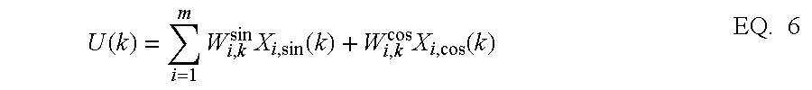
- Adaptive feedforward cancellation generates a correction value at each sector that is added to the servo loop. In general, this correction value is calculated as:
- N is the number of sectors in one revolution of the disc.
- each tap weight is a function of the tap weight of the previous sector and the measured position error signal of the previous sector.
- the tap weights are defined as:
- W 1 ( k+ 1) W 1 ( k )+ C ( k ) ⁇ PES ( k ) ⁇ X 1 ( k ) EQ. 4
- W 2 ( k+ 1) W 2 ( k )+ C ( k ) ⁇ PES ( k ) ⁇ X 2 ( k ) EQ. 5
- C(k) is a learning rate and PES(k) is the position error signal for the kth sector.
- Equation 1 only the fundamental frequency is cancelled by the cancellation value.
- W i,k+1 cos W i,k cos +C ( k ) ⁇ PES ( k ) ⁇ X i,cos ( k ) EQ. 10
- the adaptive feedforward cancellation system 200 implements equations 6 through 10 using a microprocessor 220 , a random access memory 222 , and a sine and cosine table 224 .
- microprocessor 220 generates a set of new tap weights using the tap weights for the previous sector and the position error signal for the previous sector, which is taken from analog-to-digital converter 214 .
- Microprocessor 220 multiplies the position error signal by the learning rate, which is stored in random access memory 222 and a sine or cosine function for the previous sector stored in sine and cosine table 224 .
- Microprocessor 220 then multiplies each new tap weight by a respective sine or cosine value for the current sector stored in sine and cosine table 224 .
- the servo loop of FIG. 2 may be simplified by combining elements and assigning a single gain to the combined elements.
- An example of a simplified block diagram is shown in FIG. 5 where an actuator block 450 with a gain of P is shown in place of digital-to-analog component 208 , power amplifier 210 , head-disc assembly 212 and analog-to-digital converter 214 .
- Controller 204 of FIG. 2 is shown as controller block 452 in FIG. 5 and has a gain of C.
- the adaptive feedforward cancellation circuit is shown as AFC block 454 .
- the repeatable runout disturbance is shown as a disturbance d that is added to the position information output by actuator 450 .
- the feedforward cancellation signal is shown as U, which is subtracted from the control signal produced by controller 452 .
- AFC 450 One factor that determines how quickly AFC 450 cancels the repeatable runout is the response of the servo loop to changes in the cancellation signal U. Specifically, since AFC 450 adjusts its cancellation signal based on the position error signal it receives, the degree to which the position error signal changes due to a change in the cancellation signal U will affect the rate at which AFC 450 converges on a cancellation signal. If a small change in the cancellation signal results in a large change in the position error signal, it is generally more difficult for AFC 450 to arrive at a final cancellation signal since the PES will tend to oscillate because of changes in the cancellation signal. Ideally, a change in the cancellation signal results in a similar sized change in the position error signal at all frequencies.
- the relationship between the PES signal and the cancellation signal can be determined.
- this relationship is defined in terms of a transfer function G that is equal to the change in the PES signal over the corresponding change in the cancellation signal. This can be determined from FIG. 5 by setting the reference signal and the repeatable runout signal to zero and tracing the servo loop. Thus, from FIG. 5 it is apparent that:
- this transfer function is equal to one for all frequencies such that a change in the cancellation signal results in an equal change in the position error signal detected by AFC 450 .
- this transfer function is rarely if ever equal to one and in many disc drives is highly frequency dependent. As such, the convergence of prior adaptive feedforward cancellation systems is less than ideal.
- FIG. 6 provides a block diagram of an embodiment of the present invention showing the new filter as filter 526 , which has a gain of F.
- the remainder of the servo loop 502 is similar to that of FIG. 2 and consists of a controller 504 , summer 506 , digital-to-analog converter 508 , power amplifier 510 , head-disc assembly 512 , and analog-to-digital converter 514 .
- the remainder of the adaptive feedforward cancellation system 500 is also similar to the system of FIG. 2 and includes a microprocessor 520 , a Random Access Memory 522 and a sine and cosine table 524 .
- (PES)′ is the PES signal provided to the AFC system by filter 526 .
- the present invention thereby improves the convergence of the AFC system.
- filter 526 is realized as third order filter 600 of FIG. 7 .
- Filter 600 includes two delay units 602 and 604 that delay the PES values by one sector each and three weighting blocks 606 (b 0 ), 608 (b 1 ), and 610 (b 2 ) that weight the contributions of the current PES value, the preceding PES value and the second preceding PES value, respectively.
- the outputs of the weighting blocks are summed together with a delayed and weighted version of the previous filter output ⁇ 0 produced by a delay unit 612 and a weighting block 614 (a 0 ).
- the resulting output of the filter is shown as y and is defined as:
- PES(k) is the position error signal for the current sector k.
- filter 600 may be implemented in programmable hardware or software.
- FIG. 8 provides a flow diagram for practicing one embodiment of the present invention.
- the process of FIG. 8 begins at step 700 where the closed-loop frequency response of the servo system is determined.
- the closed-loop response including introducing signals of various frequencies at the input and measuring the resulting position error signals.
- this measurement provides a response represented by (1/1+CP).
- the mechanical frequency response of the actuator (P) is measured. This can be done by modeling the actuator or by applying control signals of various frequencies to the actuator and measuring the resulting error signals produced by the head.
- the transfer function G is inverted and fit to real numerator and denominator coefficients to form the filter parameters (b 0 , b 1 , b 2 , and a 0 ) of filter F.
- This can be achieved using control software such as MATLAB (available from Mathworks, Inc. of Natick, Mass.). Specifically, the ‘invfreqz’ function of MATLAB may be used.
- steps 700 through 706 are only performed once for each disc drive and thereafter the filter remains fixed.
- i represents the harmonic of the fundamental sector frequency
- m is the total number of harmonics of interest
- W i,k+1 cos and W i,k+1 sin are harmonic specific adaptive tap weights that are initially set to zero.
- the position error signal produced for the first current sector (k) is passed through the F filter ( 526 in FIG. 6, 600 in FIG. 7) to produce a filtered PES value ⁇ . This value is then used at step 714 to update the tap weights for the next sector (k+1) for all harmonics using the equations:
- W i,k+1 cos and W i,k+1 sin are the tap weights for the next sector k+1 and the ith harmonic
- W i,k cos and W i,k sin are the tap weights for the current sector (k) and the ith harmonic
- p is a learning rate.
- the learning rate is adaptive such that it generally decreases with each sector.
- equation 17 above is used to generate a new cancellation signal at step 716 .
- This new cancellation signal is then applied at the next sector and the process returns to step 712 where the next sector becomes the current sector.
- FIGS. 9, 10 , 11 and 12 are graphs showing the improved performance of the present invention over the prior art. These graphs were generated by a simulation based on a disc containing 120 sectors per track rotating at 75 Hz.
- FIGS. 9 and 10 show the effects of cancellation signals generated under the prior art and the present invention, respectively. Equation 17 was used to generate the cancellation signal in both cases. However, the tap weights were updated differently. Specifically, under the prior art technique, the position error signal was used directly in equations 18 and 19 in place of the filtered position error signal, ⁇ , of the present invention. FIGS. 9 and 10 do not depict the effects on all frequencies of the position error signal but instead only show the effects on the portion of the position error signal at the fundamental frequency. In FIGS. 9 and 10, the position error signal is shown along vertical axes 800 and 900 , respectively and time is shown along horizontal axes 802 and 902 . To achieve these results, a learning rate, ⁇ , of 0.01 was used for the prior art and a learning rate of 0.1 was used for the present invention. The learning rate of 0.01 for the prior art was limited by the need for convergence.
- FIGS. 11 and 12 show the cancellation effects of the prior art and present invention, respectively, with regard to the fourth harmonic of the position error signal.
- the position error signal is shown along vertical axes 1000 and 1100 and time is shown along horizontal axes 1002 , and 1102 .
- the prior art learning rate was limited to 0.001.
- the same learning rate of 0.1 that was used for the fundamental frequency is used for the fourth harmonic. This results in a cancellation of the fourth harmonic in about the same amount of time that was required to cancel the fundamental frequency component using the present invention.
- the present invention improves the cancellation of higher frequency components of the reapatable runout and cancels all of the frequency components in about the same amount of time. Under one embodiment, all of the frequency components were nearly reduced to null within one revolution of the disc.
- a method for generating an adaptive feedforward cancellation signal, U, for a next sector 304 of a disc 300 in a disc drive 100 .
- the cancellation signal includes at least one tap weight, W i,k+1 cos , multiplied by at least one trigonometric function, cos[i(k+1)(2 ⁇ /N)].
- the method of generating the cancellation signal includes determining a servo loop transfer function, G, relative to a feedforward cancellation component 454 and inverting the transfer function to form filter parameters.
- a position error value is then measured at a current sector, k, and the position error value is passed through a filter 526 to create a filtered position error value.
- a tap weight, W i,k+1 cos , for the next sector is then determined based in part on the filtered position error value and a tap weight, W i,k cos , for the current sector.
- a servo system for a disc drive 100 includes a controller 504 for generating a control signal and an actuator-head assembly 508 , 510 , 512 , and 514 that is capable of moving the head based at least in part on the control signal.
- the actuator-head assembly is also capable of generating the position error signal based on the position of the head over a track 322 .
- An adaptive feedforward cancellation component 500 receives a filtered position error signal from a filter 526 and is capable of producing a cancellation signal for a next sector based in part on the filtered position error signal.
- the transfer function of filter 526 approaches the inverse of the transfer function from the output, U, of the adaptive feedforward cancellation component 500 to the input of the filter 526 .
Abstract
Description


Claims (15)


Priority Applications (7)
| Application Number | Priority Date | Filing Date | Title |
|---|---|---|---|
| US09/467,989 US6487035B1 (en) | 1999-01-15 | 1999-12-20 | Method and apparatus for adaptive feedforward cancellation |
| GB0116182A GB2361577B (en) | 1999-01-15 | 2000-01-14 | Method and apparatus for adaptive feedforward cancellation |
| PCT/US2000/001014 WO2000042603A1 (en) | 1999-01-15 | 2000-01-14 | Method and apparatus for adaptive feedforward cancellation |
| DE10083806T DE10083806T1 (en) | 1999-01-15 | 2000-01-14 | Adaptive forward erasure method and apparatus |
| CN00802823A CN1337045A (en) | 1999-01-15 | 2000-01-14 | Method and apparatus for adaptive feedforward cancellation |
| KR1020017008878A KR20010113648A (en) | 1999-01-15 | 2000-01-14 | Method and apparatus for adaptive feedforward cancellation |
| JP2000594110A JP2002535795A (en) | 1999-01-15 | 2000-01-14 | Method and apparatus for adaptive feedforward cancellation |
Applications Claiming Priority (2)
| Application Number | Priority Date | Filing Date | Title |
|---|---|---|---|
| US11607199P | 1999-01-15 | 1999-01-15 | |
| US09/467,989 US6487035B1 (en) | 1999-01-15 | 1999-12-20 | Method and apparatus for adaptive feedforward cancellation |
Publications (1)
| Publication Number | Publication Date |
|---|---|
| US6487035B1 true US6487035B1 (en) | 2002-11-26 |
Family
ID=26813870
Family Applications (1)
| Application Number | Title | Priority Date | Filing Date |
|---|---|---|---|
| US09/467,989 Expired - Lifetime US6487035B1 (en) | 1999-01-15 | 1999-12-20 | Method and apparatus for adaptive feedforward cancellation |
Country Status (7)
| Country | Link |
|---|---|
| US (1) | US6487035B1 (en) |
| JP (1) | JP2002535795A (en) |
| KR (1) | KR20010113648A (en) |
| CN (1) | CN1337045A (en) |
| DE (1) | DE10083806T1 (en) |
| GB (1) | GB2361577B (en) |
| WO (1) | WO2000042603A1 (en) |
Cited By (18)
| Publication number | Priority date | Publication date | Assignee | Title |
|---|---|---|---|---|
| US6574067B2 (en) * | 2000-02-25 | 2003-06-03 | Seagate Technology Llc | Optimally designed parsimonious repetitive learning compensator for hard disc drives having high track density |
| US6618219B1 (en) * | 1999-10-12 | 2003-09-09 | Seagate Technology Llc | Method and apparatus for feedforward cancellation using a peak detector |
| US6628472B1 (en) * | 1999-10-12 | 2003-09-30 | Seagate Technoogy Llc | Method and apparatus for feedforward cancellation using a phase lock loop |
| US20030193736A1 (en) * | 2002-04-11 | 2003-10-16 | Min Shuangquan | Method and apparatus for feedforward repeatable runout compensation in a selected frequency range |
| US6710966B1 (en) * | 2001-10-23 | 2004-03-23 | Western Digital Technologies, Inc. | Method for reducing an effect of vibration on a disk drive during a track following operation by adjusting an adaptive-filter gain applied to an acceleration sensor signal |
| US20050018344A1 (en) * | 2003-07-24 | 2005-01-27 | Hitachi Global Storage Technologies | Method and apparatus for determining modulated, amplitude ramping RRO harmonics in multi-screw clamped HDD disk/spindle assembly |
| US20050094307A1 (en) * | 2003-10-30 | 2005-05-05 | Kabushiki Kaisha Toshiba | Method and apparatus for positioning a head in a disk drive with servo writing function |
| US6972922B1 (en) * | 2003-02-07 | 2005-12-06 | Western Digital Technologies, Inc. | Disk drive having internal data structures for efficiently storing repeatable runout cancellation information |
| US6987638B1 (en) | 2002-05-03 | 2006-01-17 | Maxtor Corporation | Method and apparatus for applying adaptive non-linear repeatable runout compensation in a disk drive |
| US6999267B1 (en) * | 2004-04-28 | 2006-02-14 | Western Digital Technologies, Inc. | Method for iteratively determining repeatable runout cancellation values in a magnetic disk drive |
| US20080112073A1 (en) * | 2006-11-13 | 2008-05-15 | Fujifilm Corporation | Apparatus, system, and method for repeatable runout cancellation |
| US20080239555A1 (en) * | 2007-03-30 | 2008-10-02 | Toshiba America Information Systems, Inc. | Multi-quadrant wedge offset reduction field values for disk drive servo |
| US20100014186A1 (en) * | 2007-04-27 | 2010-01-21 | Fujitsu Limited | Position control apparatus and disk apparatus using the same |
| US20100014185A1 (en) * | 2007-04-27 | 2010-01-21 | Fujitsu Limited | Position control apparatus and disk apparatus using the same |
| US20100067134A1 (en) * | 2008-09-18 | 2010-03-18 | Kumbla Kishan K | Adaptive track shape control during self servo-write |
| US8982503B1 (en) | 2013-01-21 | 2015-03-17 | Western Digital Technologies, Inc. | Disk drive generating feed-forward compensation value based on two points of a sinusoidal control signal |
| US10539946B2 (en) | 2016-05-12 | 2020-01-21 | Siemens Aktiengesellschaft | Closed-loop control device with adaptive fault compensation |
| US11495255B2 (en) * | 2020-09-18 | 2022-11-08 | Kabushiki Kaisha Toshiba | Method for manufacturing magnetic disk device |
Families Citing this family (9)
| Publication number | Priority date | Publication date | Assignee | Title |
|---|---|---|---|---|
| CN1470056A (en) * | 2000-10-13 | 2004-01-21 | 西加特技术有限责任公司 | Suspension sense capability for windage control |
| US6762902B2 (en) * | 2000-12-15 | 2004-07-13 | Samsung Electronics Co., Ltd. | Time-varying, non-synchronous disturbance identification and cancellation in a rotating disk storage device |
| JP2005317130A (en) | 2004-04-28 | 2005-11-10 | Toshiba Corp | Disk recording device, control system and method for head positioning |
| KR100640646B1 (en) | 2005-06-27 | 2006-11-01 | 삼성전자주식회사 | Disturbance compensating method of state control device, and apparatus and recording medium for the same |
| US7787210B1 (en) * | 2009-03-17 | 2010-08-31 | Headway Technologies, Inc. | Feed-forward method for repeatable runout cancellation |
| US7894156B2 (en) * | 2009-03-30 | 2011-02-22 | Kabushiki Kaisha Toshiba | Determination of wedge offset correction values for a disk drive |
| CN105374372A (en) * | 2014-08-28 | 2016-03-02 | 株式会社东芝 | Disc device, controlling device and method |
| JP2016212930A (en) * | 2015-04-28 | 2016-12-15 | 株式会社東芝 | Memory device, controller and control method |
| CN109538538A (en) * | 2018-11-28 | 2019-03-29 | 努比亚技术有限公司 | A kind of processing method of fan noise, mobile terminal and storage medium |
Citations (15)
| Publication number | Priority date | Publication date | Assignee | Title |
|---|---|---|---|---|
| US4135217A (en) | 1976-11-02 | 1979-01-16 | Xerox Corporation | Utilization of stored run-out information in a track following servo system |
| US4536809A (en) | 1982-05-10 | 1985-08-20 | Digital Equipment Corporation | Adaptive misposition correcting method and apparatus for magnetic disk servo system |
| US4616276A (en) | 1985-07-16 | 1986-10-07 | International Business Machines Corporation | Disk file servo control system with fast reduction of repeatable head position error |
| US5402280A (en) | 1992-05-11 | 1995-03-28 | Quantum Corp. | Method and apparatus for runout correction due to disk slip or spindle imbalance |
| US5404253A (en) | 1993-06-24 | 1995-04-04 | Fujitsu Limited | Estimator-based runout compensation in a disk drive |
| JPH0798948A (en) * | 1993-09-30 | 1995-04-11 | Toshiba Corp | Magnetic disk device |
| US5550685A (en) * | 1993-10-22 | 1996-08-27 | Syquest Technology, Inc. | Applying an adaptive feed-forward algorithm as a frequency selective filter in a closed loop disk drive servo system in order to compensate for periodic perturbations which otherwise appear in the servo system position error signal |
| US5585976A (en) | 1994-06-22 | 1996-12-17 | Seagate Technology, Inc. | Digital sector servo incorporating repeatable run out tracking |
| US5592346A (en) | 1994-03-31 | 1997-01-07 | Polaroid Corporation | Control system utilizing an adaptive predictor to compensate for harmonic distortion |
| US5602689A (en) | 1990-09-18 | 1997-02-11 | Rodime Plc | Digital servo control system for use in disk drives, including sample integrity tester for reducing effects of spurious sampled position values |
| US5615065A (en) | 1994-10-04 | 1997-03-25 | International Business Machines Corporation | Phase-compensated servo pattern and position error-sensing detector |
| US5774299A (en) * | 1996-08-13 | 1998-06-30 | Seagate Technology, Inc. | Adaptive calibration of read/write elements in a disc drive |
| US5854722A (en) | 1993-08-26 | 1998-12-29 | International Business Machines Corporation | Method and apparatus for rotary actuator arc compensation correction in a direct access storage device |
| US5875066A (en) | 1996-12-13 | 1999-02-23 | International Business Machines Corporation | Method and apparatus for real-time filtering of a position error signal for a disk drive servo system |
| US5923491A (en) * | 1995-09-25 | 1999-07-13 | International Business Machines Corporation | Disk drive servo control system with selectable filtering for reduction of repeatable runout |
-
1999
- 1999-12-20 US US09/467,989 patent/US6487035B1/en not_active Expired - Lifetime
-
2000
- 2000-01-14 GB GB0116182A patent/GB2361577B/en not_active Expired - Fee Related
- 2000-01-14 WO PCT/US2000/001014 patent/WO2000042603A1/en not_active Application Discontinuation
- 2000-01-14 DE DE10083806T patent/DE10083806T1/en not_active Withdrawn
- 2000-01-14 KR KR1020017008878A patent/KR20010113648A/en not_active Application Discontinuation
- 2000-01-14 CN CN00802823A patent/CN1337045A/en active Pending
- 2000-01-14 JP JP2000594110A patent/JP2002535795A/en active Pending
Patent Citations (15)
| Publication number | Priority date | Publication date | Assignee | Title |
|---|---|---|---|---|
| US4135217A (en) | 1976-11-02 | 1979-01-16 | Xerox Corporation | Utilization of stored run-out information in a track following servo system |
| US4536809A (en) | 1982-05-10 | 1985-08-20 | Digital Equipment Corporation | Adaptive misposition correcting method and apparatus for magnetic disk servo system |
| US4616276A (en) | 1985-07-16 | 1986-10-07 | International Business Machines Corporation | Disk file servo control system with fast reduction of repeatable head position error |
| US5602689A (en) | 1990-09-18 | 1997-02-11 | Rodime Plc | Digital servo control system for use in disk drives, including sample integrity tester for reducing effects of spurious sampled position values |
| US5402280A (en) | 1992-05-11 | 1995-03-28 | Quantum Corp. | Method and apparatus for runout correction due to disk slip or spindle imbalance |
| US5404253A (en) | 1993-06-24 | 1995-04-04 | Fujitsu Limited | Estimator-based runout compensation in a disk drive |
| US5854722A (en) | 1993-08-26 | 1998-12-29 | International Business Machines Corporation | Method and apparatus for rotary actuator arc compensation correction in a direct access storage device |
| JPH0798948A (en) * | 1993-09-30 | 1995-04-11 | Toshiba Corp | Magnetic disk device |
| US5550685A (en) * | 1993-10-22 | 1996-08-27 | Syquest Technology, Inc. | Applying an adaptive feed-forward algorithm as a frequency selective filter in a closed loop disk drive servo system in order to compensate for periodic perturbations which otherwise appear in the servo system position error signal |
| US5592346A (en) | 1994-03-31 | 1997-01-07 | Polaroid Corporation | Control system utilizing an adaptive predictor to compensate for harmonic distortion |
| US5585976A (en) | 1994-06-22 | 1996-12-17 | Seagate Technology, Inc. | Digital sector servo incorporating repeatable run out tracking |
| US5615065A (en) | 1994-10-04 | 1997-03-25 | International Business Machines Corporation | Phase-compensated servo pattern and position error-sensing detector |
| US5923491A (en) * | 1995-09-25 | 1999-07-13 | International Business Machines Corporation | Disk drive servo control system with selectable filtering for reduction of repeatable runout |
| US5774299A (en) * | 1996-08-13 | 1998-06-30 | Seagate Technology, Inc. | Adaptive calibration of read/write elements in a disc drive |
| US5875066A (en) | 1996-12-13 | 1999-02-23 | International Business Machines Corporation | Method and apparatus for real-time filtering of a position error signal for a disk drive servo system |
Cited By (27)
| Publication number | Priority date | Publication date | Assignee | Title |
|---|---|---|---|---|
| US6618219B1 (en) * | 1999-10-12 | 2003-09-09 | Seagate Technology Llc | Method and apparatus for feedforward cancellation using a peak detector |
| US6628472B1 (en) * | 1999-10-12 | 2003-09-30 | Seagate Technoogy Llc | Method and apparatus for feedforward cancellation using a phase lock loop |
| US6574067B2 (en) * | 2000-02-25 | 2003-06-03 | Seagate Technology Llc | Optimally designed parsimonious repetitive learning compensator for hard disc drives having high track density |
| US6710966B1 (en) * | 2001-10-23 | 2004-03-23 | Western Digital Technologies, Inc. | Method for reducing an effect of vibration on a disk drive during a track following operation by adjusting an adaptive-filter gain applied to an acceleration sensor signal |
| US20030193736A1 (en) * | 2002-04-11 | 2003-10-16 | Min Shuangquan | Method and apparatus for feedforward repeatable runout compensation in a selected frequency range |
| US6859341B2 (en) | 2002-04-11 | 2005-02-22 | Seagate Technology Llc | Method and apparatus for feedforward repeatable runout compensation in a selected frequency range |
| US6987638B1 (en) | 2002-05-03 | 2006-01-17 | Maxtor Corporation | Method and apparatus for applying adaptive non-linear repeatable runout compensation in a disk drive |
| US6972922B1 (en) * | 2003-02-07 | 2005-12-06 | Western Digital Technologies, Inc. | Disk drive having internal data structures for efficiently storing repeatable runout cancellation information |
| US6992853B2 (en) | 2003-07-24 | 2006-01-31 | Hitachi Global Storage Technologies Netherlands B.V | Method and apparatus for determining modulated, amplitude ramping RRO harmonics in multi-screw clamped HDD disk/spind assembly |
| US20050018344A1 (en) * | 2003-07-24 | 2005-01-27 | Hitachi Global Storage Technologies | Method and apparatus for determining modulated, amplitude ramping RRO harmonics in multi-screw clamped HDD disk/spindle assembly |
| US7061710B2 (en) | 2003-10-30 | 2006-06-13 | Kabushiki Kaisha Toshiba | Method and apparatus for positioning a head in a disk drive with servo writing function |
| US20050094307A1 (en) * | 2003-10-30 | 2005-05-05 | Kabushiki Kaisha Toshiba | Method and apparatus for positioning a head in a disk drive with servo writing function |
| US6999267B1 (en) * | 2004-04-28 | 2006-02-14 | Western Digital Technologies, Inc. | Method for iteratively determining repeatable runout cancellation values in a magnetic disk drive |
| US7688541B2 (en) * | 2006-11-13 | 2010-03-30 | Boyd Norvell Shelton | Apparatus, system, and method for repeatable runout cancellation |
| US20080112073A1 (en) * | 2006-11-13 | 2008-05-15 | Fujifilm Corporation | Apparatus, system, and method for repeatable runout cancellation |
| US20090296266A1 (en) * | 2006-11-13 | 2009-12-03 | Boyd Norvell Shelton | Apparatus, system, and method for repeatable runout cancellation |
| US7903367B2 (en) | 2006-11-13 | 2011-03-08 | Fujifilm Corporation | Apparatus, system, and method for repeatable runout cancellation |
| US20080239555A1 (en) * | 2007-03-30 | 2008-10-02 | Toshiba America Information Systems, Inc. | Multi-quadrant wedge offset reduction field values for disk drive servo |
| US8068307B2 (en) * | 2007-04-27 | 2011-11-29 | Toshiba Storage Device Corporation | Position control apparatus and disk apparatus using the same |
| US20100014185A1 (en) * | 2007-04-27 | 2010-01-21 | Fujitsu Limited | Position control apparatus and disk apparatus using the same |
| US8049987B2 (en) * | 2007-04-27 | 2011-11-01 | Toshiba Storage Device Corporation | Position control apparatus and disk apparatus using the same |
| US20100014186A1 (en) * | 2007-04-27 | 2010-01-21 | Fujitsu Limited | Position control apparatus and disk apparatus using the same |
| US20100067134A1 (en) * | 2008-09-18 | 2010-03-18 | Kumbla Kishan K | Adaptive track shape control during self servo-write |
| US7881004B2 (en) * | 2008-09-18 | 2011-02-01 | Hitachi Global Storage Technologies, Netherlands, B.V. | Adaptive track shape control during self servo-write |
| US8982503B1 (en) | 2013-01-21 | 2015-03-17 | Western Digital Technologies, Inc. | Disk drive generating feed-forward compensation value based on two points of a sinusoidal control signal |
| US10539946B2 (en) | 2016-05-12 | 2020-01-21 | Siemens Aktiengesellschaft | Closed-loop control device with adaptive fault compensation |
| US11495255B2 (en) * | 2020-09-18 | 2022-11-08 | Kabushiki Kaisha Toshiba | Method for manufacturing magnetic disk device |
Also Published As
| Publication number | Publication date |
|---|---|
| GB0116182D0 (en) | 2001-08-22 |
| GB2361577B (en) | 2002-12-11 |
| JP2002535795A (en) | 2002-10-22 |
| KR20010113648A (en) | 2001-12-28 |
| GB2361577A (en) | 2001-10-24 |
| DE10083806T1 (en) | 2002-03-07 |
| WO2000042603A1 (en) | 2000-07-20 |
| CN1337045A (en) | 2002-02-20 |
Similar Documents
| Publication | Publication Date | Title |
|---|---|---|
| US6487035B1 (en) | Method and apparatus for adaptive feedforward cancellation | |
| CA1228418A (en) | Disk file servo control system with fast reduction of repeatable head position error | |
| US6751045B1 (en) | Compensation for repeatable run-out error | |
| US6437936B1 (en) | Repeatable runout compensation using a learning algorithm with scheduled parameters | |
| US6785084B2 (en) | Correction of dynamic track spacing errors in storage devices | |
| US6449116B2 (en) | Compression and storage of written-in error compensation tables in an embedded servo disc drive | |
| US6563663B1 (en) | Repeatable runout compensation using iterative learning control in a disc storage system | |
| US6608731B2 (en) | Dynamic reduction of track shape errors in disc drives | |
| KR100430318B1 (en) | Method of implementing a linear discrete-time state-space servo control system on a fixed-point digital signal processor in a disc drive | |
| US6549362B1 (en) | Method and apparatus for the enhancement of embedded runout correction in a disk drive | |
| US7119981B2 (en) | Method and apparatus for tracking radially-dependent repeatable run-out | |
| KR20010022682A (en) | Model validation algorithm for characterizing parameters and uncertainty in a disc drive | |
| JP2000505581A (en) | In-drive correction of servo pattern errors | |
| US6636376B1 (en) | Disc drive resonance disturbance cancellation filter | |
| US20020089779A1 (en) | Reducing disc drive position error signal nonlinearity through iterative calibration of a compensation table | |
| US6751046B1 (en) | Writing servo data patterns on a data storage disk to account for repeatable and non-repeatable disturbances and thereby provide concentric data tracks | |
| US7167336B1 (en) | Method for providing variable gain, iterative embedded runout correction in a disk drive | |
| US20050046994A1 (en) | Fractional-rate feedforward RRO compensator | |
| US20020012191A1 (en) | Repeated runout position error compensation in a disc drive servo system | |
| US6963466B2 (en) | Radial dependent low frequency repeatable run out compensation apparatus and method | |
| US7719787B2 (en) | Phase locked anti- notch filter in a servo control loop | |
| US6292324B1 (en) | Disk drive with compensation values calculated using a non-causal impulse response | |
| US6618219B1 (en) | Method and apparatus for feedforward cancellation using a peak detector | |
| US6804079B2 (en) | Written-in repeatable run-out compensation in embedded servo disc drives | |
| US6970321B2 (en) | Automatic model regulation in a disc drive servo system using model reference inverse |
Legal Events
| Date | Code | Title | Description |
|---|---|---|---|
| AS | Assignment |
Owner name: SEAGATE TECHNOLOGY, INC., CALIFORNIA Free format text: ASSIGNMENT OF ASSIGNORS INTEREST;ASSIGNORS:LIU, XIONG;LIU, JOSEPH CHENG-TSU;GOMEZ, KEVIN A.;AND OTHERS;REEL/FRAME:010520/0248 Effective date: 19991217 |
|
| AS | Assignment |
Owner name: SEAGATE TECHNOLOGY LLC, CALIFORNIA Free format text: ASSIGNMENT OF ASSIGNORS INTEREST;ASSIGNOR:SEAGATE TECHNOLOGY, INC.;REEL/FRAME:010986/0853 Effective date: 20000628 |
|
| AS | Assignment |
Owner name: JPMORGAN CHASE BANK, AS COLLATERAL AGENT, NEW YORK Free format text: SECURITY AGREEMENT;ASSIGNOR:SEAGATE TECHNOLOGY LLC;REEL/FRAME:013177/0001 Effective date: 20020513 Owner name: JPMORGAN CHASE BANK, AS COLLATERAL AGENT,NEW YORK Free format text: SECURITY AGREEMENT;ASSIGNOR:SEAGATE TECHNOLOGY LLC;REEL/FRAME:013177/0001 Effective date: 20020513 |
|
| STCF | Information on status: patent grant |
Free format text: PATENTED CASE |
|
| CC | Certificate of correction | ||
| FEPP | Fee payment procedure |
Free format text: PAYER NUMBER DE-ASSIGNED (ORIGINAL EVENT CODE: RMPN); ENTITY STATUS OF PATENT OWNER: LARGE ENTITY Free format text: PAYOR NUMBER ASSIGNED (ORIGINAL EVENT CODE: ASPN); ENTITY STATUS OF PATENT OWNER: LARGE ENTITY |
|
| AS | Assignment |
Owner name: SEAGATE TECHNOLOGY LLC, CALIFORNIA Free format text: RELEASE OF SECURITY INTERESTS IN PATENT RIGHTS;ASSIGNOR:JPMORGAN CHASE BANK, N.A. (FORMERLY KNOWN AS THE CHASE MANHATTAN BANK AND JPMORGAN CHASE BANK), AS ADMINISTRATIVE AGENT;REEL/FRAME:016958/0328 Effective date: 20051130 |
|
| REMI | Maintenance fee reminder mailed | ||
| FPAY | Fee payment |
Year of fee payment: 4 |
|
| SULP | Surcharge for late payment | ||
| AS | Assignment |
Owner name: JPMORGAN CHASE BANK, N.A., AS ADMINISTRATIVE AGENT Free format text: SECURITY AGREEMENT;ASSIGNORS:MAXTOR CORPORATION;SEAGATE TECHNOLOGY LLC;SEAGATE TECHNOLOGY INTERNATIONAL;REEL/FRAME:022757/0017 Effective date: 20090507 Owner name: WELLS FARGO BANK, NATIONAL ASSOCIATION, AS COLLATE Free format text: SECURITY AGREEMENT;ASSIGNORS:MAXTOR CORPORATION;SEAGATE TECHNOLOGY LLC;SEAGATE TECHNOLOGY INTERNATIONAL;REEL/FRAME:022757/0017 Effective date: 20090507 |
|
| FPAY | Fee payment |
Year of fee payment: 8 |
|
| AS | Assignment |
Owner name: SEAGATE TECHNOLOGY HDD HOLDINGS, CALIFORNIA Free format text: RELEASE;ASSIGNOR:JPMORGAN CHASE BANK, N.A., AS ADMINISTRATIVE AGENT;REEL/FRAME:025662/0001 Effective date: 20110114 Owner name: SEAGATE TECHNOLOGY INTERNATIONAL, CALIFORNIA Free format text: RELEASE;ASSIGNOR:JPMORGAN CHASE BANK, N.A., AS ADMINISTRATIVE AGENT;REEL/FRAME:025662/0001 Effective date: 20110114 Owner name: SEAGATE TECHNOLOGY LLC, CALIFORNIA Free format text: RELEASE;ASSIGNOR:JPMORGAN CHASE BANK, N.A., AS ADMINISTRATIVE AGENT;REEL/FRAME:025662/0001 Effective date: 20110114 Owner name: MAXTOR CORPORATION, CALIFORNIA Free format text: RELEASE;ASSIGNOR:JPMORGAN CHASE BANK, N.A., AS ADMINISTRATIVE AGENT;REEL/FRAME:025662/0001 Effective date: 20110114 |
|
| AS | Assignment |
Owner name: THE BANK OF NOVA SCOTIA, AS ADMINISTRATIVE AGENT, Free format text: SECURITY AGREEMENT;ASSIGNOR:SEAGATE TECHNOLOGY LLC;REEL/FRAME:026010/0350 Effective date: 20110118 |
|
| AS | Assignment |
Owner name: SEAGATE TECHNOLOGY LLC, CALIFORNIA Free format text: TERMINATION AND RELEASE OF SECURITY INTEREST IN PATENT RIGHTS;ASSIGNOR:WELLS FARGO BANK, NATIONAL ASSOCIATION, AS COLLATERAL AGENT AND SECOND PRIORITY REPRESENTATIVE;REEL/FRAME:030833/0001 Effective date: 20130312 Owner name: SEAGATE TECHNOLOGY INTERNATIONAL, CAYMAN ISLANDS Free format text: TERMINATION AND RELEASE OF SECURITY INTEREST IN PATENT RIGHTS;ASSIGNOR:WELLS FARGO BANK, NATIONAL ASSOCIATION, AS COLLATERAL AGENT AND SECOND PRIORITY REPRESENTATIVE;REEL/FRAME:030833/0001 Effective date: 20130312 Owner name: SEAGATE TECHNOLOGY US HOLDINGS, INC., CALIFORNIA Free format text: TERMINATION AND RELEASE OF SECURITY INTEREST IN PATENT RIGHTS;ASSIGNOR:WELLS FARGO BANK, NATIONAL ASSOCIATION, AS COLLATERAL AGENT AND SECOND PRIORITY REPRESENTATIVE;REEL/FRAME:030833/0001 Effective date: 20130312 Owner name: EVAULT INC. (F/K/A I365 INC.), CALIFORNIA Free format text: TERMINATION AND RELEASE OF SECURITY INTEREST IN PATENT RIGHTS;ASSIGNOR:WELLS FARGO BANK, NATIONAL ASSOCIATION, AS COLLATERAL AGENT AND SECOND PRIORITY REPRESENTATIVE;REEL/FRAME:030833/0001 Effective date: 20130312 |
|
| FPAY | Fee payment |
Year of fee payment: 12 |