US6282055B1 - Magnetic tape head with combination bleed and transverse slotted contour - Google Patents
Magnetic tape head with combination bleed and transverse slotted contour Download PDFInfo
- Publication number
- US6282055B1 US6282055B1 US09/434,199 US43419999A US6282055B1 US 6282055 B1 US6282055 B1 US 6282055B1 US 43419999 A US43419999 A US 43419999A US 6282055 B1 US6282055 B1 US 6282055B1
- Authority
- US
- United States
- Prior art keywords
- bleed
- slots
- slot
- transverse
- magnetic gap
- Prior art date
- Legal status (The legal status is an assumption and is not a legal conclusion. Google has not performed a legal analysis and makes no representation as to the accuracy of the status listed.)
- Expired - Lifetime
Links
Images


Classifications
-
- G—PHYSICS
- G11—INFORMATION STORAGE
- G11B—INFORMATION STORAGE BASED ON RELATIVE MOVEMENT BETWEEN RECORD CARRIER AND TRANSDUCER
- G11B5/00—Recording by magnetisation or demagnetisation of a record carrier; Reproducing by magnetic means; Record carriers therefor
- G11B5/10—Structure or manufacture of housings or shields for heads
-
- G—PHYSICS
- G11—INFORMATION STORAGE
- G11B—INFORMATION STORAGE BASED ON RELATIVE MOVEMENT BETWEEN RECORD CARRIER AND TRANSDUCER
- G11B5/00—Recording by magnetisation or demagnetisation of a record carrier; Reproducing by magnetic means; Record carriers therefor
- G11B5/127—Structure or manufacture of heads, e.g. inductive
- G11B5/187—Structure or manufacture of the surface of the head in physical contact with, or immediately adjacent to the recording medium; Pole pieces; Gap features
- G11B5/1871—Shaping or contouring of the transducing or guiding surface
-
- G—PHYSICS
- G11—INFORMATION STORAGE
- G11B—INFORMATION STORAGE BASED ON RELATIVE MOVEMENT BETWEEN RECORD CARRIER AND TRANSDUCER
- G11B15/00—Driving, starting or stopping record carriers of filamentary or web form; Driving both such record carriers and heads; Guiding such record carriers or containers therefor; Control thereof; Control of operating function
- G11B15/60—Guiding record carrier
- G11B15/62—Maintaining desired spacing between record carrier and head
- G11B15/64—Maintaining desired spacing between record carrier and head by fluid-dynamic spacing
Definitions
- the present invention relates to a magnetic tape head having a contour that includes multiple bleed slots and multiple transverse slots.
- data storage efficiency can be reduced by entrained air that causes separation between a magnetic tape and a recording head as the tape moves over the head.
- separation losses can be reduced by providing bleed slots in the head that extend in the direction of tape travel.
- air can still become entrained between the tape and slot islands located between adjacent bleed slots, thereby causing separation losses and a degradation of performance.
- the bleed slots must be made wider, and the slot islands therefore narrower, in order to account for increased entrained air.
- the narrower the slot islands the more difficult they are to manufacture and the more prone they are to breakage.
- U.S. Pat. No. 5,953,184 which is assigned to the assignee of the present invention, discloses a magnetic tape head that includes an interior tape head module sandwiched between two exterior tape head modules. Each of the modules has a magnetic gap and a transverse slot on each side of the magnetic gap for removing entrained air.
- the invention provides a magnetic tape head having a contour that includes multiple bleed slots in combination with multiple transverse slots to effectively reduce separation losses.
- the head further includes first and second slotted regions disposed proximate the outer edges of the first and second transverse slots, respectively. Each slotted region includes a plurality of bleed slots extending in a direction non-perpendicular to the direction of motion of the tape. The transverse slots and the slotted regions cooperate to remove air entrained between the head and the tape as the tape moves over the head.
- the bleed slots of the first and second slotted regions are in fluid communication with the first and second transverse slots, respectively.
- Such a configuration maximizes removal of entrained air.
- each bleed slot has a breakout point that is less than 0.0115 inches from the magnetic gap. Furthermore, each bleed slot preferably has a breakout point that is less than 0.007 inches from the magnetic gap.
- the magnetic gap of the head may include an active element region having a lateral dimension that is less than a lateral dimension of the head.
- Each slotted region preferably extends only along the lateral dimension of the active element region.
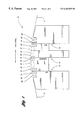
- FIG. 1 is a side view of an exemplary tape head assembly according to the invention and including a contour having multiple transverse slots and multiple bleed slots;
- FIG. 2 is an exploded side view of the tape head assembly
- FIG. 3 is a perspective view of the tape head assembly showing the bleed slots in fluid communication with the transverse slots;
- FIG. 4 is a top view of the tape head assembly
- FIG. 5 is a top view of the tape head assembly similar to FIG. 4 and showing an alternative configuration of the bleed slots.
- FIGS. 1 through 4 show an exemplary embodiment of a tape head assembly 10 according to the invention.
- tape head assembly 10 includes various features that combine to create a robust, high performance bi-directional tape head contour for receiving a tape 11 thereon.
- the direction of tape travel is denoted by the arrows labeled “TAPE TRAVEL”.
- Tape head assembly 10 comprises three tape head modules 12 , 14 and 16 , including interior module 14 and exterior modules 12 and 16 .
- the exterior modules 12 and 16 are preferably wider than the interior module 14 to account for variations in tape wrap angle.
- exterior modules 12 and 16 are preferably 0.105 inches wide, while interior module 14 is preferably 0.060 inches wide.
- each module 12 , 14 and 16 preferably has a radius of curvature of approximately 0.390 inches.
- Each module 12 , 14 and 16 further has a magnetic gap 18 , and each magnetic gap 18 may contain one or more active elements, such as read elements and write elements, disposed in an active element region 19 . Therefore, tape head assembly 10 may be constructed with various read and write configurations. However, tape head assembly 10 is preferably a “read-write-read” assembly. That is, exterior module 12 preferably comprises a read element, interior module 14 comprises a write element, and exterior module 16 comprises a read element. Furthermore, each active element region 19 preferably has a lateral dimension that is less than a lateral dimension of a respective module 12 , 14 or 16 . The apex or highest point of interior module 14 is located at the gap 18 of interior module 14 , while the apex of each exterior module 12 and 16 is located at a distance of 0.030 inches from the module's respective gap 18 toward interior module 14 .
- the spacing between gaps 18 of modules 12 , 14 and 16 must be reduced to prevent azimuth alignment errors.
- the spacing between gaps 18 is preferably 0.060 inches.
- bleed slots alone cannot be provided with sufficient length to adequately eliminate entrained air, particularly at higher tape speeds and with use of thinner tape 11 .
- bleed slots alone are not sufficient because bleed slots induce non-uniform head/tape spacing across the width of the tape 11 .
- each module 12 , 14 and 16 is provided with one transverse slot 20 on each side of the module's respective gap 18 , and a slotted region 22 disposed between adjacent gaps 18 . Because the slotted regions 22 and transverse slots 20 can be provided with any suitable spacing therebetween, or no spacing at all, such an arrangement is particularly useful with multi-gap tape heads having relatively small gap-to-gap spacing requirements.
- Each transverse slot 20 has inner and outer edges 24 and 26 , respectively.
- Each transverse slot 20 also preferably has a width in the direction of tape travel of 0.007 inches, and a depth of at least 0.015 inches.
- each transverse slot 20 of each module 12 , 14 and 16 has a centerline 27 that is preferably located 0.008 inches from the module's respective gap 18 .
- the slotted regions 22 are preferably disposed along the outer edges 26 of the transverse slots 20 , and each slotted region 22 has a plurality of bleed slots 28 that are preferably in fluid communication with a respective transverse slot 20 .
- the slotted regions 22 may be spaced away from the outer edges 26 of the transverse slots 20 .
- each of the slotted regions 22 preferably extends laterally only along the lateral dimension of a respective active element region 19 . With such a configuration, damage to edges of the tape 11 may be substantially reduced or eliminated as the tape head assembly 10 is moved laterally across the tape 11 .
- Each bleed slot 28 has a bottom surface 30 that defines a slot-angle ⁇ with respect to a horizontal line 32 . While ⁇ may be in the range of 0 to 90°, ⁇ is preferably 35°. Because each bleed slot 28 is preferably in fluid communication with a respective transverse slot 20 , each bottom surface 30 may not extend to an arcuate surface 34 of the tape head assembly 10 over which the tape 11 travels. In other words, each bleed slot 28 may not have an actual breakout point, or point at which a respective bottom surface 30 breaks through or contacts the arcuate surface 34 . Nonetheless, a line coincident with the bottom surface 30 of each bleed slot 28 may be extended to an arc joining adjacent portions of the arcuate surface 34 to define an imaginary breakout point.
- each bleed slot 28 preferably has a breakout point that is at or near the inner edge 24 of a respective transverse slot 20 . More specifically, each bleed slot 28 of each module 12 , 14 and 16 preferably has a breakout point that is approximately 0.0045 to 0.0065 inches from the module's respective gap 18 .
- each slotted region 22 are separated by islands 35 .
- Each bleed slot 28 preferably has a width of 0.0107 inches, and each island 35 preferably has a width of 0.0055 inches.
- the bleed slots 28 disposed at opposite ends of each slotted region 22 have centerlines that are preferably located 0.287 inches from opposite lateral sides 36 of the tape head assembly 10 .
- each bleed slot 28 preferably extends in the direction of tape travel for ease of manufacture. In other words, each bleed slot 28 preferably extends at an angle of 0° with respect to the direction of tape travel. Alternatively, one or more bleed slots 28 may extend in a direction nonperpendicular to the direction of tape travel. In other words, each of the bleed slots 28 may extend at an angle between +90° and ⁇ 90° with respect to the direction of tape travel. If the bleed slots 28 extend at a angles other than 0°, the bleed slots 28 are able to remove air along the length of the tape 11 , as well as across the tape 11 . Consequently, air removal will be maximized and non-uniform tape/head spacing will be minimized. As shown in FIG. 5, the bleed slots 28 of adjacent slotted regions 22 may also extend in different directions with respect to the direction of tape travel.
- each exterior module 12 and 16 is preferably provided with an additional transverse slot 38 disposed between each module's respective gap 18 and an outer side of the tape head assembly 10 .
- the transverse slots 38 also function to trap debris from the surface of the tape as the tape travels over the tape head assembly 10 . Because the exterior modules 12 and 16 are wider than the interior module 14 , additional space is available to accommodate the transverse slots 38 .
- Each transverse slot 38 of each exterior module 12 and 16 has a centerline that is preferably located 0.022 inches from the module's respective gap 18 . Furthermore, each transverse slot 38 also preferably has a width in the direction of tape travel of 0.007 inches, and a depth of at least 0.015 inches.
- transverse slots 20 and 38 and slotted regions 22 While the locations and dimensions of transverse slots 20 and 38 and slotted regions 22 detailed above are preferable, other locations and dimensions may also be used. Moreover, additional slotted regions (not shown) may also be provided on exterior modules 12 and 16 outside of transverse slots 38 , or in lieu of transverse slots 38 .
- the transverse slots 20 and 38 In order for the transverse slots 20 and 38 to adequately remove entrained air, the transverse slots 20 and 38 should be covered by the tape 11 when the tape 11 is stationary. Therefore, the preferred locations of stationary tangent points of the tape 11 on each of the modules 12 , 14 and 16 , such that transverse slots 20 may adequately function to defeat entrained air and debris, are each greater than 0.0115 inches from the module's respective gap 18 , and preferably in the range of 0.022 to 0.023 inches from the module's respective gap 18 .
- the preferred location of a stationary tangent point of the tape 11 on each exterior module 12 and 16 where the tape 11 first comes into contact with the tape head assembly 10 is greater than 0.0255 inches from the module's respective gap 18 , and preferably in the range of 0.045 to 0.049 inches from the module's respective gap 18 .
- the preferred tangent point locations of the tape 11 with respect to the transverse slots 20 also satisfy minimum coverage or engagement points of the bleed slots 28 , wherein minimum engagement points are measured from the breakout points of the bleed slots 28 .
- the depth of the bleed slot 28 in a direction perpendicular to a tangent plane of the tape 11 , and with respect to an adjacent island 35 should be at least ten times the thickness of the tape 11 .
- the minimum engagement point for each bleed slot 28 is approximately 0.004 inches from the bleed slot's breakout point.
- the minimum engagement point for each bleed slot 28 preferably falls within a respective transverse slot 20 .
- the tape head assembly 10 is able to effectively maximize removal of entrained air while minimizing gap-to-gap spacing. Furthermore, because the bleed slots 28 are preferably located along the outer edges 26 of the transverse slots 20 , any non-uniform spacing introduced by the bleed slots 28 may be eliminated by the transverse slots 20 before the tape 11 passes over the gaps 18 .
- the contour of tape head assembly 10 may be manufactured with existing wafer, machining, and assembly processes.
- the bleed slots 28 are formed first by machining each module 12 , 14 and 16 .
- the transverse slots 20 and 38 may be formed such that the bleed slots 28 are in fluid communication with the transverse slots 20 .
Abstract
Description
Claims (39)
Priority Applications (1)
| Application Number | Priority Date | Filing Date | Title |
|---|---|---|---|
| US09/434,199 US6282055B1 (en) | 1999-11-04 | 1999-11-04 | Magnetic tape head with combination bleed and transverse slotted contour |
Applications Claiming Priority (1)
| Application Number | Priority Date | Filing Date | Title |
|---|---|---|---|
| US09/434,199 US6282055B1 (en) | 1999-11-04 | 1999-11-04 | Magnetic tape head with combination bleed and transverse slotted contour |
Publications (1)
| Publication Number | Publication Date |
|---|---|
| US6282055B1 true US6282055B1 (en) | 2001-08-28 |
Family
ID=23723225
Family Applications (1)
| Application Number | Title | Priority Date | Filing Date |
|---|---|---|---|
| US09/434,199 Expired - Lifetime US6282055B1 (en) | 1999-11-04 | 1999-11-04 | Magnetic tape head with combination bleed and transverse slotted contour |
Country Status (1)
| Country | Link |
|---|---|
| US (1) | US6282055B1 (en) |
Cited By (15)
| Publication number | Priority date | Publication date | Assignee | Title |
|---|---|---|---|---|
| US20020075594A1 (en) * | 2000-12-11 | 2002-06-20 | Fujitsu Limited | Read/write head for a magnetic tape device having grooves for reducing tape floating |
| US20040047076A1 (en) * | 2002-09-10 | 2004-03-11 | Tandberg Data Asa | Write/read head assembly |
| US20040228029A1 (en) * | 2003-05-16 | 2004-11-18 | George Saliba | Tape head with thin support surface and method of manufacture |
| US20050134989A1 (en) * | 2003-12-18 | 2005-06-23 | Carolyn Girvin | Multi-format thinfilm head and associated methods |
| US20060056109A1 (en) * | 2004-09-16 | 2006-03-16 | Saliba George A | Magnetic head with adaptive data island and mini-outrigger and methods of manufacture |
| US20060056108A1 (en) * | 2004-09-16 | 2006-03-16 | Saliba George A | Magnetic head with mini-outriggers and method of manufacture |
| US20070047142A1 (en) * | 2005-08-26 | 2007-03-01 | International Business Machines Corporation | Flat profile tape head |
| US20070183091A1 (en) * | 2006-02-03 | 2007-08-09 | Saliba George A | Read/write head having varying wear regions and methods of manufacture |
| US20080170328A1 (en) * | 2007-01-12 | 2008-07-17 | Shinji Kawakami | Magnetic head |
| US20110181982A1 (en) * | 2010-01-22 | 2011-07-28 | Fujifilm Corporation | Servo write head, servo writer, and method for manufacturing magnetic tape with servo signal written thereon |
| US8861132B2 (en) | 2010-07-06 | 2014-10-14 | International Business Machines Corporation | Low friction tape head and system implementing same |
| US20150364154A1 (en) * | 2013-03-22 | 2015-12-17 | Hewlett-Packard Development Company, L.P. | Reduced contact read/write head |
| US20160055867A1 (en) * | 2014-08-20 | 2016-02-25 | International Business Machines Corporation | Tape heads with sub-ambient pressure cavities |
| US10490211B2 (en) * | 2018-03-16 | 2019-11-26 | International Business Machines Corporation | Tape head module having recessed portion to provide an air bearing between a tape medium and a tape bearing surface of the module |
| US11031031B2 (en) | 2018-05-01 | 2021-06-08 | International Business Machines Corporation | Forming recessed portions in a tape head module to provide an air bearing between a tape medium and a tape bearing surface of the tape head module |
Citations (2)
| Publication number | Priority date | Publication date | Assignee | Title |
|---|---|---|---|---|
| US3872507A (en) * | 1972-02-04 | 1975-03-18 | Matsushita Electric Ind Co Ltd | Rotating air bearing head with shaped control slots |
| US6038108A (en) * | 1997-11-21 | 2000-03-14 | Storage Technology Corporation | Magnetic tape head assembly having segmented heads |
-
1999
- 1999-11-04 US US09/434,199 patent/US6282055B1/en not_active Expired - Lifetime
Patent Citations (2)
| Publication number | Priority date | Publication date | Assignee | Title |
|---|---|---|---|---|
| US3872507A (en) * | 1972-02-04 | 1975-03-18 | Matsushita Electric Ind Co Ltd | Rotating air bearing head with shaped control slots |
| US6038108A (en) * | 1997-11-21 | 2000-03-14 | Storage Technology Corporation | Magnetic tape head assembly having segmented heads |
Cited By (35)
| Publication number | Priority date | Publication date | Assignee | Title |
|---|---|---|---|---|
| US20020075594A1 (en) * | 2000-12-11 | 2002-06-20 | Fujitsu Limited | Read/write head for a magnetic tape device having grooves for reducing tape floating |
| US6927937B2 (en) * | 2000-12-11 | 2005-08-09 | Fujitsu Limited | Read/write head for a magnetic tape device having grooves for reducing tape floating |
| US6972931B2 (en) * | 2002-09-10 | 2005-12-06 | Tandberg Data Asa | Write/read head assembly with wear parts |
| US20040047076A1 (en) * | 2002-09-10 | 2004-03-11 | Tandberg Data Asa | Write/read head assembly |
| US20040228029A1 (en) * | 2003-05-16 | 2004-11-18 | George Saliba | Tape head with thin support surface and method of manufacture |
| US6937435B2 (en) | 2003-05-16 | 2005-08-30 | Quantum Corporation | Tape head with thin support surface and method of manufacture |
| US20050134989A1 (en) * | 2003-12-18 | 2005-06-23 | Carolyn Girvin | Multi-format thinfilm head and associated methods |
| US7154691B2 (en) | 2003-12-18 | 2006-12-26 | Quantum Corporation | Multi-format thinfilm head and associated methods |
| US20060056109A1 (en) * | 2004-09-16 | 2006-03-16 | Saliba George A | Magnetic head with adaptive data island and mini-outrigger and methods of manufacture |
| US20060056108A1 (en) * | 2004-09-16 | 2006-03-16 | Saliba George A | Magnetic head with mini-outriggers and method of manufacture |
| US8223456B2 (en) | 2004-09-16 | 2012-07-17 | Quantum Corporation | Method for manufacturing a magnetic head with mini-outriggers |
| US20080037170A1 (en) * | 2004-09-16 | 2008-02-14 | Quantum Corporation | Magnetic head with mini-outriggers and method of manufacture |
| US7256963B2 (en) | 2004-09-16 | 2007-08-14 | Quantum Corporation | Magnetic head with adaptive data island and mini-outrigger and methods of manufacture |
| US7271983B2 (en) | 2004-09-16 | 2007-09-18 | Quantum Corporation | Magnetic head with mini-outriggers and method of manufacture |
| US7414811B2 (en) * | 2005-08-26 | 2008-08-19 | International Business Machines Corporation | Magnetic head having three modules |
| US20080259494A1 (en) * | 2005-08-26 | 2008-10-23 | Robert Glenn Biskeborn | Flat profile tape head |
| US8054579B2 (en) | 2005-08-26 | 2011-11-08 | International Business Machines Corporation | Magnetic head having three modules |
| US20070047142A1 (en) * | 2005-08-26 | 2007-03-01 | International Business Machines Corporation | Flat profile tape head |
| US8254058B2 (en) * | 2005-08-26 | 2012-08-28 | International Business Machines Corporation | Flat profile tape head |
| US20070183091A1 (en) * | 2006-02-03 | 2007-08-09 | Saliba George A | Read/write head having varying wear regions and methods of manufacture |
| US8310783B2 (en) * | 2007-01-12 | 2012-11-13 | Hitachi Maxell, Ltd. | Magnetic tape head with limited ranges of tape wrap angle and distance between first and second edges |
| US20080170328A1 (en) * | 2007-01-12 | 2008-07-17 | Shinji Kawakami | Magnetic head |
| US20110181982A1 (en) * | 2010-01-22 | 2011-07-28 | Fujifilm Corporation | Servo write head, servo writer, and method for manufacturing magnetic tape with servo signal written thereon |
| US8451561B2 (en) * | 2010-01-22 | 2013-05-28 | Fujifilm Corporation | Servo write head, servo writer, and method for manufacturing magnetic tape with servo signal written thereon |
| US9299368B2 (en) | 2010-07-06 | 2016-03-29 | International Business Machines Corporation | Low friction tape head |
| US8861132B2 (en) | 2010-07-06 | 2014-10-14 | International Business Machines Corporation | Low friction tape head and system implementing same |
| US9653109B2 (en) | 2010-07-06 | 2017-05-16 | International Business Machines Corporation | Low friction tape head |
| US20150364154A1 (en) * | 2013-03-22 | 2015-12-17 | Hewlett-Packard Development Company, L.P. | Reduced contact read/write head |
| US20160111120A1 (en) * | 2014-08-20 | 2016-04-21 | International Business Machines Corporation | Tape heads with sub-ambient pressure cavities |
| US20160055867A1 (en) * | 2014-08-20 | 2016-02-25 | International Business Machines Corporation | Tape heads with sub-ambient pressure cavities |
| US9734854B2 (en) * | 2014-08-20 | 2017-08-15 | International Business Machines Corporation | Tape heads with sub-ambient pressure cavities |
| US9761259B2 (en) * | 2014-08-20 | 2017-09-12 | International Business Machines Corporation | Tape heads with sub-ambient pressure cavities |
| US10490211B2 (en) * | 2018-03-16 | 2019-11-26 | International Business Machines Corporation | Tape head module having recessed portion to provide an air bearing between a tape medium and a tape bearing surface of the module |
| US10902868B2 (en) | 2018-03-16 | 2021-01-26 | International Business Machines Corporation | Tape head module having recessed portion to provide an air bearing between a tape medium and a tape bearing surface of the module |
| US11031031B2 (en) | 2018-05-01 | 2021-06-08 | International Business Machines Corporation | Forming recessed portions in a tape head module to provide an air bearing between a tape medium and a tape bearing surface of the tape head module |
Similar Documents
| Publication | Publication Date | Title |
|---|---|---|
| US6282055B1 (en) | Magnetic tape head with combination bleed and transverse slotted contour | |
| US8223456B2 (en) | Method for manufacturing a magnetic head with mini-outriggers | |
| US6937435B2 (en) | Tape head with thin support surface and method of manufacture | |
| US6433959B1 (en) | Tape head contour utilizing enclosed through slots | |
| KR100270281B1 (en) | Bidirectional flat contour linear tape recording head and drive | |
| US6122147A (en) | Negative pressure head contour in a linear tape recording system with tape deforming cavity | |
| US5751527A (en) | Magnetic tape head contour with land widths to optimize flying height and a sufficient number of bleed slots to uniformly maintain the flying height of the tape | |
| JP4840929B2 (en) | Magnetic head | |
| US4695909A (en) | Magnetic head assembly | |
| US8675310B2 (en) | Embedded chip tape head | |
| US20070183091A1 (en) | Read/write head having varying wear regions and methods of manufacture | |
| US10902868B2 (en) | Tape head module having recessed portion to provide an air bearing between a tape medium and a tape bearing surface of the module | |
| US20040047076A1 (en) | Write/read head assembly | |
| US6927937B2 (en) | Read/write head for a magnetic tape device having grooves for reducing tape floating | |
| CN103377657B (en) | There is the module of quilting type coating, data-storage system and magnetic recording head | |
| US6057983A (en) | Flying head slider in which adhesion of a liquid dust is suppressed | |
| KR20220126675A (en) | Electronic component array and base tape | |
| JP6445014B2 (en) | Read / write head with improved contact | |
| US7256963B2 (en) | Magnetic head with adaptive data island and mini-outrigger and methods of manufacture | |
| US6359753B1 (en) | Floating magnetic head for use with flexible disks | |
| US5625513A (en) | Floating head slider having uniform spacing from recording medium surface | |
| US6243232B1 (en) | Magnetic head | |
| US5644449A (en) | Magnetic head slider assembly | |
| JP3605304B2 (en) | Multitrack magnetic head | |
| US6396662B1 (en) | High/low density magnetic head slider with lateral incision |
Legal Events
| Date | Code | Title | Description |
|---|---|---|---|
| AS | Assignment |
Owner name: STORAGE TECHNOLOGY CORPORATION, COLORADO Free format text: ASSIGNMENT OF ASSIGNORS INTEREST;ASSIGNORS:LAKSHMIKUMARAN, ANAND V.;BARBER, TERRY J.;REEL/FRAME:010376/0325 Effective date: 19991101 |
|
| STCF | Information on status: patent grant |
Free format text: PATENTED CASE |
|
| FEPP | Fee payment procedure |
Free format text: PAYOR NUMBER ASSIGNED (ORIGINAL EVENT CODE: ASPN); ENTITY STATUS OF PATENT OWNER: LARGE ENTITY |
|
| FPAY | Fee payment |
Year of fee payment: 4 |
|
| FPAY | Fee payment |
Year of fee payment: 8 |
|
| FPAY | Fee payment |
Year of fee payment: 12 |
|
| AS | Assignment |
Owner name: ORACLE AMERICA, INC., CALIFORNIA Free format text: MERGER AND CHANGE OF NAME;ASSIGNORS:SUN MICROSYSTEMS, INC.;ORACLE USA, INC.;ORACLE AMERICA, INC.;REEL/FRAME:037692/0970 Effective date: 20100212 Owner name: SUN MICROSYSTEMS, INC., CALIFORNIA Free format text: MERGER;ASSIGNOR:STORAGE TECHNOLOGY CORPORATION;REEL/FRAME:037695/0339 Effective date: 20061222 |