US6038108A - Magnetic tape head assembly having segmented heads - Google Patents
Magnetic tape head assembly having segmented heads Download PDFInfo
- Publication number
- US6038108A US6038108A US08/975,645 US97564597A US6038108A US 6038108 A US6038108 A US 6038108A US 97564597 A US97564597 A US 97564597A US 6038108 A US6038108 A US 6038108A
- Authority
- US
- United States
- Prior art keywords
- elements
- tape head
- module
- read
- exterior
- Prior art date
- Legal status (The legal status is an assumption and is not a legal conclusion. Google has not performed a legal analysis and makes no representation as to the accuracy of the status listed.)
- Expired - Lifetime
Links
Images


Classifications
-
- G—PHYSICS
- G11—INFORMATION STORAGE
- G11B—INFORMATION STORAGE BASED ON RELATIVE MOVEMENT BETWEEN RECORD CARRIER AND TRANSDUCER
- G11B5/00—Recording by magnetisation or demagnetisation of a record carrier; Reproducing by magnetic means; Record carriers therefor
- G11B5/127—Structure or manufacture of heads, e.g. inductive
- G11B5/33—Structure or manufacture of flux-sensitive heads, i.e. for reproduction only; Combination of such heads with means for recording or erasing only
- G11B5/39—Structure or manufacture of flux-sensitive heads, i.e. for reproduction only; Combination of such heads with means for recording or erasing only using magneto-resistive devices or effects
- G11B5/3903—Structure or manufacture of flux-sensitive heads, i.e. for reproduction only; Combination of such heads with means for recording or erasing only using magneto-resistive devices or effects using magnetic thin film layers or their effects, the films being part of integrated structures
- G11B5/3967—Composite structural arrangements of transducers, e.g. inductive write and magnetoresistive read
-
- G—PHYSICS
- G11—INFORMATION STORAGE
- G11B—INFORMATION STORAGE BASED ON RELATIVE MOVEMENT BETWEEN RECORD CARRIER AND TRANSDUCER
- G11B5/00—Recording by magnetisation or demagnetisation of a record carrier; Reproducing by magnetic means; Record carriers therefor
- G11B5/127—Structure or manufacture of heads, e.g. inductive
- G11B5/31—Structure or manufacture of heads, e.g. inductive using thin films
- G11B5/3103—Structure or manufacture of integrated heads or heads mechanically assembled and electrically connected to a support or housing
- G11B5/3106—Structure or manufacture of integrated heads or heads mechanically assembled and electrically connected to a support or housing where the integrated or assembled structure comprises means for conditioning against physical detrimental influence, e.g. wear, contamination
-
- G—PHYSICS
- G11—INFORMATION STORAGE
- G11B—INFORMATION STORAGE BASED ON RELATIVE MOVEMENT BETWEEN RECORD CARRIER AND TRANSDUCER
- G11B5/00—Recording by magnetisation or demagnetisation of a record carrier; Reproducing by magnetic means; Record carriers therefor
- G11B5/48—Disposition or mounting of heads or head supports relative to record carriers ; arrangements of heads, e.g. for scanning the record carrier to increase the relative speed
- G11B5/488—Disposition of heads
- G11B5/4893—Disposition of heads relative to moving tape
-
- G—PHYSICS
- G11—INFORMATION STORAGE
- G11B—INFORMATION STORAGE BASED ON RELATIVE MOVEMENT BETWEEN RECORD CARRIER AND TRANSDUCER
- G11B5/00—Recording by magnetisation or demagnetisation of a record carrier; Reproducing by magnetic means; Record carriers therefor
- G11B5/48—Disposition or mounting of heads or head supports relative to record carriers ; arrangements of heads, e.g. for scanning the record carrier to increase the relative speed
- G11B5/58—Disposition or mounting of heads or head supports relative to record carriers ; arrangements of heads, e.g. for scanning the record carrier to increase the relative speed with provision for moving the head for the purpose of maintaining alignment of the head relative to the record carrier during transducing operation, e.g. to compensate for surface irregularities of the latter or for track following
- G11B5/584—Disposition or mounting of heads or head supports relative to record carriers ; arrangements of heads, e.g. for scanning the record carrier to increase the relative speed with provision for moving the head for the purpose of maintaining alignment of the head relative to the record carrier during transducing operation, e.g. to compensate for surface irregularities of the latter or for track following for track following on tapes
-
- G—PHYSICS
- G11—INFORMATION STORAGE
- G11B—INFORMATION STORAGE BASED ON RELATIVE MOVEMENT BETWEEN RECORD CARRIER AND TRANSDUCER
- G11B5/00—Recording by magnetisation or demagnetisation of a record carrier; Reproducing by magnetic means; Record carriers therefor
- G11B5/127—Structure or manufacture of heads, e.g. inductive
- G11B5/33—Structure or manufacture of flux-sensitive heads, i.e. for reproduction only; Combination of such heads with means for recording or erasing only
- G11B5/39—Structure or manufacture of flux-sensitive heads, i.e. for reproduction only; Combination of such heads with means for recording or erasing only using magneto-resistive devices or effects
- G11B5/3903—Structure or manufacture of flux-sensitive heads, i.e. for reproduction only; Combination of such heads with means for recording or erasing only using magneto-resistive devices or effects using magnetic thin film layers or their effects, the films being part of integrated structures
- G11B5/3906—Details related to the use of magnetic thin film layers or to their effects
- G11B5/3945—Heads comprising more than one sensitive element
- G11B5/3948—Heads comprising more than one sensitive element the sensitive elements being active read-out elements
- G11B5/3951—Heads comprising more than one sensitive element the sensitive elements being active read-out elements the active elements being arranged on several parallel planes
- G11B5/3954—Heads comprising more than one sensitive element the sensitive elements being active read-out elements the active elements being arranged on several parallel planes the active elements transducing on a single track
-
- G—PHYSICS
- G11—INFORMATION STORAGE
- G11B—INFORMATION STORAGE BASED ON RELATIVE MOVEMENT BETWEEN RECORD CARRIER AND TRANSDUCER
- G11B5/00—Recording by magnetisation or demagnetisation of a record carrier; Reproducing by magnetic means; Record carriers therefor
- G11B5/48—Disposition or mounting of heads or head supports relative to record carriers ; arrangements of heads, e.g. for scanning the record carrier to increase the relative speed
- G11B5/54—Disposition or mounting of heads or head supports relative to record carriers ; arrangements of heads, e.g. for scanning the record carrier to increase the relative speed with provision for moving the head into or out of its operative position or across tracks
- G11B5/55—Track change, selection or acquisition by displacement of the head
- G11B5/5504—Track change, selection or acquisition by displacement of the head across tape tracks
Definitions
- the present invention relates to a magnetic tape head assembly with multiple tape head modules designed for bi-directional, high speed, high density tape storage applications.
- Such problems include recording high density patterns on high coercivity tape media.
- the tape head assembly must perform read while write operations in both forward and backward direction of tape motion at high tape speeds.
- the tape head assembly must be moveable perpendicular to the direction of tape motion to allow multiple passes of the tape with the head in different cross tape locations.
- the tape head assembly must provide active track following servo capability. Still further, as the number of recording or reproducing elements on a tape head increases, the spacing between adjacent elements in the tape head is much tighter.
- the relatively poor guiding of the tape requires that the spacing between a write element and a read verify in the tape head assembly must decrease in order to ensure that the read is located on the proper written track.
- a multi-element, thin film tape head assembly for use in a tape drive that will use high coercivity half-inch wide tape media (e.g., >1600 Oe Metal Particle) and a high recording density (e.g., 70 kfci base with 200-400 kfci write equalization recording).
- Such a tape head assembly would perform read while write operations in both forward and backward direction of tape motion at a tape speed of 2-4 m/s, and would be moveable perpendicular to the direction of tape motion to allow multiple passes of the tape.
- such a tape head assembly would include 16 tape head elements, would provide active track following servo capability using 6 servo reading elements, and would have alignment between read and write elements of better than 5 ⁇ m.
- a principle object of the present invention is to provide an improved bidirectional, high speed, multi-gap, high density tape head assembly.
- a magnetic tape head assembly for use with a magnetic tape storage medium.
- the assembly comprises an interior tape head module having a magnetic gap provided therein, the interior module having at least 16 tape head elements along the magnetic gap, and a first exterior tape head module having a magnetic gap provided therein, the first exterior module being disposed adjacent one side of the interior module, the first exterior module having at least 16 tape head elements along the magnetic gap.
- the assembly further comprises a second exterior tape head module having a magnetic gap provided therein, the second exterior module being disposed adjacent to another side of the interior module, the second exterior module having at least 16 tape head elements along the magnetic gap.
- the distances between consecutive magnetic gaps of the interior and exterior modules are each approximately 0.060 inches (60 mils), and the interior and exterior modules together define a tape interface contour.
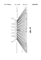
- FIG. 1 is a perspective view of one embodiment of the multi-track, bi-directional thin film tape head assembly of the present invention
- FIGS. 2a and 2b are views of alternative embodiments of a multi-element, thin film write head for use in the present invention.
- FIGS. 3a and 3b are views of alternative embodiments of a multi-element, thin film read head for use in the present invention.
- FIG. 1 is a perspective view of one embodiment of the multi-element, bi-directional thin film tape head assembly of the present invention, denoted generally by reference numeral 10.
- tape head assembly (10) is a three segment head comprising a first read head (12), a write head (14), and a second read head (16).
- write head (14) contains 16 thin film write elements (not shown) positioned symmetrically between read heads (12, 16), each containing 22 biased magneto-resistive (MR) read elements (not shown)
- MR magneto-resistive
- tape head assembly (10) is a read/write/read design. While preferred, such a read/write/read design is not required for the present invention.
- each read and write head (12, 14, 16) includes a magnetic gap (18).
- the spacing between gaps (18) of read head (12) and write head (14), as well as write head (14) and read head (16) is 60 mils to aid reducing the effect of azimuth on offtrack issues.
- the contour of tape head assembly (10) is shaped for bi-directional operation by using cylindrical surfaces and transverse air bleed slots (20).
- the read data elements are arranged in 4 groups of 4 or 2 groups of 8 to allow the servo tracks and readers to be positioned in between.
- the three head modules (12, 14, 16) are preferably fixed into an aluminum frame (not shown) with electrical connections preferably made by direct attached thermosonic bonding (not shown).
- the cables are preferably single layer shielded copper/Kapton based "flex" cables. It should be noted that this design may also include shields (not shown) or air ducts (not shown) between modules (12, 14, 16).
- the read/write/read configuration described above is preferred, but alternatives are possible. These include a write/read/write configuration, or an interleaved read/write two module arrangement.
- the separation of reads and writes via the three module head gives lower feedthrough and an easier thin film head manufacturing process.
- Each side can be independently optimized and the yield of one does not compromise the yield of the other.
- the thin film manufacturing process for the tape heads for use in such an assembly requires high precision and is very time-consuming. It is therefore desirable to design a tape head assembly that minimizes the complexity of the process. This is best accomplished by minimizing the number of tape head modules in the tape head assembly and by allowing for maximum tolerances in the assembly of the required modules.
- While assembly of a three module head is more complex than a two module head, the two module design involves interleaving the reads and writes in the thin film area, thereby increasing the process complexity, as well as the flex circuit and connector density.
- the cable and card (and crosstalk) complexity is much reduced as separation of the reads and writes is done in the head rather than in the cable or on the card.
- locating the servo readers in the read (only) gap provides low feedthrough from the write when writing. In contrast, using reads in the write gap has high feedthrough and complicates the thin film head manufacturing process.
- FIGS. 2 and 3 views of alternative embodiments of multi-element, thin film read and write heads for use in the present invention are shown.
- FIGS. 2a and 2b depict single and dual band embodiments of write head (14) of FIG. 1.
- FIGS. 3a and 3b depict single and dual band embodiments of read heads (12, 16) of FIG. 1.
- the dual band embodiments of read and write heads (12, 14, 16) of FIG. 1 are designed to decrease the affect of tape dimensional instability over time by subdividing the tape into two halves.
- write head (14) of FIG. 1 includes 16 write elements (21).
- Each write element (21) is a 5 or 6 turn inductive device with Cobalt-Zirconium-Tantalum poles constructed on an Aluminum-Titanium-Carbide or a Nickel-Zinc ferrite base.
- the pole width that defines the track width on tape is 36 ⁇ m wide and the gap length is approximately 0.60-0.75 ⁇ m.
- write elements (21) may be arranged as a single band of 4 groups of 4 write elements (21) to allow the servo tracks and readers to be positioned in between (FIG. 2a).
- write elements (21) may be arranged in 2 bands of 8 write elements (21) (FIG.
- each band has an approximately 0.25 inch span for two positions across a 0.5 inch tape.
- the tape head assembly of the present invention is designed for use in a 0.5 inch, two reel cassette (cartridge) .
- write head also includes lapping sensors (not shown) at each end thereof.
- read heads (12, 16) of FIG. 1 include 22 read elements (24a, 24b).
- Each read element (24a, 24b) is a coupled element (dual stripe) magneto-resistive (MR) element sandwiched between two Nickel-Zinc ferrite blocks that act as magnetic shields.
- the active element width is approximately 16-28 ⁇ m and the shield-to-shield spacing is approximately 0.4-0.55 ⁇ m.
- read elements (24a, 24b) may be arranged as a single band of 4 groups of 4 read elements (24a), with 6 servo tracks and read elements (24b) positioned in between (FIG. 3a).
- read elements (24a, 24b) may be arranged in dual bands of 2 groups of 8 data read elements (24a), with 6 servo tracks and read elements (24b) positioned in between (2-8-2-8-2 format) (FIG. 3b).
- this arrangement is designed to account for tape dimensional instability over time by subdividing the tape into two halves.
- the servo read elements for use in the present invention may be provided with different throat heights to allow for reading of lower density servo signals.
- the tape head assembly of the present invention uses 16 tracks at a time, with 12 active servo readers. It should be noted that the tape head assembly of the present invention utilizes a common ground for pairs of tracks (not shown), rather than a common ground for all tracks. In such a fashion, the tape head assembly of the present invention lessens ground loop problems. Moreover, this layout in pairs of tracks improves packing density.
- the three tape head modules, each with 16 active tracks, provides a unique format capability of up to 288 tracks on a 0.5 inch tape. Such high density creates the need for the servo reading capability and the three module tape head assemblies described above, particularly the read/write/read configuration of the preferred embodiment.
- tape head assembly of the present invention is designed for use with various features which are shown and described in U.S. patent application Ser. No. 08/943,361 entitled “Recording Head Element With Improved Coil Tap And Method For Manufacturing Same”; Ser. No. 08/909,533 entitled “High Density Thin Film Coupled Element Read Head And Method For Manufacturing Same”; Ser. No. 08/940,185 entitled “Transverse Slotted Magnetic Tape Head Assembly For High Speed, High Density Applications”; Ser. No. 08/943,722 entitled “Multitrack Coupled Element Read Head And Method For Manufacturing Same”; Ser. No. 08/850,039 entitled “Heat Exchangeable Thin-Film Recording Head Element And Method For Manufacturing Same”; Ser.
- the present invention provides an improved bi-directional, high speed, multi-gap, high density tape head assembly. More specifically, the present invention provides a multi-element, thin film tape head assembly for use in a tape drive that will use high coercivity half-inch wide tape media and a high recording density.
- the tape head assembly of the present invention will perform bi-directional read while write operations at a tape speed of 2-4 m/s, and will be moveable perpendicular to the direction of tape motion to allow multiple passes of the tape.
- the tape head assembly of the present invention includes 16 recording elements, provides active track following servo capability using 6 servo reading elements, and has alignment between read and write elements of better than 5 ⁇ m.
- the magnetic tape head assembly of the present invention is suitable for use with any number of read and/or write heads in any combination.
Abstract
Description
Claims (8)
Priority Applications (6)
| Application Number | Priority Date | Filing Date | Title |
|---|---|---|---|
| US08/975,645 US6038108A (en) | 1997-11-21 | 1997-11-21 | Magnetic tape head assembly having segmented heads |
| AU14558/99A AU738614B2 (en) | 1997-11-21 | 1998-11-12 | Multi-track, bi-directional, high speed thin film tape head assembly |
| PCT/US1998/024062 WO1999027528A1 (en) | 1997-11-21 | 1998-11-12 | Multi-track, bi-directional, high speed thin film tape head assembly |
| JP2000522587A JP2001524729A (en) | 1997-11-21 | 1998-11-12 | Multi-track bidirectional high-speed thin film tape / head assembly structure |
| EP98958533A EP1040469A1 (en) | 1997-11-21 | 1998-11-12 | Multi-track, bi-directional, high speed thin film tape head assembly |
| CA002307029A CA2307029A1 (en) | 1997-11-21 | 1998-11-12 | Multi-track, bi-directional, high speed thin film tape head assembly |
Applications Claiming Priority (1)
| Application Number | Priority Date | Filing Date | Title |
|---|---|---|---|
| US08/975,645 US6038108A (en) | 1997-11-21 | 1997-11-21 | Magnetic tape head assembly having segmented heads |
Publications (1)
| Publication Number | Publication Date |
|---|---|
| US6038108A true US6038108A (en) | 2000-03-14 |
Family
ID=25523244
Family Applications (1)
| Application Number | Title | Priority Date | Filing Date |
|---|---|---|---|
| US08/975,645 Expired - Lifetime US6038108A (en) | 1997-11-21 | 1997-11-21 | Magnetic tape head assembly having segmented heads |
Country Status (6)
| Country | Link |
|---|---|
| US (1) | US6038108A (en) |
| EP (1) | EP1040469A1 (en) |
| JP (1) | JP2001524729A (en) |
| AU (1) | AU738614B2 (en) |
| CA (1) | CA2307029A1 (en) |
| WO (1) | WO1999027528A1 (en) |
Cited By (37)
| Publication number | Priority date | Publication date | Assignee | Title |
|---|---|---|---|---|
| US6282055B1 (en) * | 1999-11-04 | 2001-08-28 | Storage Technology Corporation | Magnetic tape head with combination bleed and transverse slotted contour |
| US6433959B1 (en) | 2000-10-30 | 2002-08-13 | Storage Technology Corporation | Tape head contour utilizing enclosed through slots |
| US6456448B1 (en) * | 1998-11-09 | 2002-09-24 | Hitachi, Ltd. | Magnetic recording system including magnetic recording medium having three-dimensional random orientation of axis of easy magnetization |
| US6611398B1 (en) * | 1999-08-09 | 2003-08-26 | Quantum Corporation | Tape head with support bars |
| US20030218092A1 (en) * | 2000-08-21 | 2003-11-27 | Anderson James C. | Tape guide with wear resistant coating |
| US6690542B1 (en) | 2000-12-13 | 2004-02-10 | Seagate Removable Storage Solutions Llc | Dual module RWW tape head assembly |
| US6781792B2 (en) | 2001-08-23 | 2004-08-24 | International Business Machines Corporation | Method and apparatus for providing tape head assemblies having U-shaped support beams for very high density recording |
| US6819528B1 (en) | 2000-10-25 | 2004-11-16 | Storage Technology Corporation | Asymmetric servo reader placement in bi-directional tape head |
| US6830183B2 (en) * | 2003-05-01 | 2004-12-14 | Semtek Innovative Solutions, Inc. | Device for secure read, write and read/modify/write operation with divided track transducer head |
| US6842312B1 (en) * | 2002-06-25 | 2005-01-11 | Storage Technology Corporation | Dual stripe read head with magnetic support structures which provide a uniform magnetic field for stabilization during manufacture |
| US20050057882A1 (en) * | 2001-08-23 | 2005-03-17 | International Business Machines Corporation | Tape head module assembly system |
| US20050134989A1 (en) * | 2003-12-18 | 2005-06-23 | Carolyn Girvin | Multi-format thinfilm head and associated methods |
| US20050259353A1 (en) * | 2004-05-18 | 2005-11-24 | Exabyte Corporation | Multi-plane thin-film heads |
| US20070091505A1 (en) * | 2005-10-25 | 2007-04-26 | International Business Machines Corporation | Magnetic head having selectively defined reader gap thicknesses |
| US20090147395A1 (en) * | 2007-12-05 | 2009-06-11 | Sun Microsystems, Inc. | Tape head layout |
| US20090231756A1 (en) * | 2008-03-12 | 2009-09-17 | Koeppe Peter Vandersalm | Multi-channel tape head having asymmetric channel arrays |
| US20090231757A1 (en) * | 2008-03-12 | 2009-09-17 | Robert Glenn Biskeborn | Head for tape drive with transversely varying contour |
| US20110176237A1 (en) * | 2010-01-21 | 2011-07-21 | International Business Machines Corporation | Magnetic tape servo format allowing for increased linear tape density and systems thereof |
| US8373944B2 (en) | 2011-05-26 | 2013-02-12 | International Business Machines Corporation | Low friction tape head and system implementing same |
| US8407786B1 (en) | 2008-06-19 | 2013-03-26 | Mcafee, Inc. | System, method, and computer program product for displaying the rating on an electronic mail message in a user-configurable manner |
| US8655959B2 (en) | 2008-01-03 | 2014-02-18 | Mcafee, Inc. | System, method, and computer program product for providing a rating of an electronic message |
| US8679733B2 (en) | 2011-01-19 | 2014-03-25 | International Business Machines Corporation | Patterning process for small devices |
| US8797682B1 (en) | 2013-08-21 | 2014-08-05 | International Business Machines Corporation | Quasi-statically tilted magnetic tape head having backward compatibility |
| US8810957B1 (en) | 2013-09-05 | 2014-08-19 | International Business Machines Corporation | Quasi-statically tilted head having dilated transducer pitch |
| US8861132B2 (en) | 2010-07-06 | 2014-10-14 | International Business Machines Corporation | Low friction tape head and system implementing same |
| US9001462B2 (en) * | 2012-11-14 | 2015-04-07 | International Business Machines Corporation | Universal magnetic recording head chip |
| US9007712B1 (en) | 2013-12-16 | 2015-04-14 | International Business Machines Corporation | Backward compatible head for quasi-static tilted reading and/or recording |
| US9117470B1 (en) | 2014-07-17 | 2015-08-25 | International Business Machines Corporation | Write delay to de-skew data in read while write function for tape storage devices |
| US9129614B2 (en) | 2013-05-01 | 2015-09-08 | International Business Machines Corporation | Magnetic head having canted arrays |
| US9208809B2 (en) | 2013-05-01 | 2015-12-08 | International Business Machines Corporation | Magnetic head and system having offset arrays |
| US9214164B2 (en) | 2013-09-16 | 2015-12-15 | International Business Machines Corporation | Miniskirt tape head having quasi-statically tilted transducer arrays |
| US9218838B2 (en) | 2013-12-12 | 2015-12-22 | International Business Machines Corporation | Quasi-statically tilted head having offset reader/writer transducer pairs |
| US9449628B2 (en) | 2013-05-01 | 2016-09-20 | International Business Machines Corporation | Quasi-statically oriented, bi-directional tape recording head |
| US11514929B2 (en) | 2021-03-30 | 2022-11-29 | Western Digital Technologies, Inc. | Magnetic recording head having same-gap read-after-write |
| US11646053B2 (en) | 2021-06-23 | 2023-05-09 | Western Digital Technologies, Inc. | Tape head design having same gap verify capabilities |
| US11646054B2 (en) | 2021-08-06 | 2023-05-09 | Western Digital Technologies, Inc. | Tape head design having an antiferromagnetic coupling (AFC) null shield for same gap verify |
| US11682421B2 (en) | 2021-06-25 | 2023-06-20 | Western Digital Technologies, Inc. | Tape head design having a null shield for same gap verify |
Families Citing this family (1)
| Publication number | Priority date | Publication date | Assignee | Title |
|---|---|---|---|---|
| US7480117B2 (en) * | 2006-12-12 | 2009-01-20 | International Business Machines Corporation | High areal density tape head |
Citations (14)
| Publication number | Priority date | Publication date | Assignee | Title |
|---|---|---|---|---|
| US4375656A (en) * | 1980-10-09 | 1983-03-01 | International Business Machines Corporation | Magnetic head assembly with asymmetric slotted configuration |
| US4479158A (en) * | 1982-05-12 | 1984-10-23 | International Business Machines Corporation | Stationary magnetic head with a fluid operated tape lifter |
| US4589042A (en) * | 1983-06-27 | 1986-05-13 | International Business Machines Corporation | Composite thin film transducer head |
| US4685005A (en) * | 1983-07-18 | 1987-08-04 | International Business Machines Corporation | Two-module-read, read-after-write, bi-directional tape drive |
| US5034838A (en) * | 1990-05-08 | 1991-07-23 | Eastman Kodak Company | Bi-directional read while write magnetic head assembly having a wear avoidance contour |
| US5142768A (en) * | 1991-05-02 | 1992-09-01 | International Business Machines Corporation | Method for making magnetic head with enhanced poletip |
| US5203119A (en) * | 1991-03-22 | 1993-04-20 | Read-Rite Corporation | Automated system for lapping air bearing surface of magnetic heads |
| US5220473A (en) * | 1991-05-08 | 1993-06-15 | Eastman Kodak Company | Multitrack magnetic head assembly having a tape-engaging surface contoured for continuous in-contact recording |
| US5264981A (en) * | 1991-08-14 | 1993-11-23 | International Business Machines Corporation | Multilayered ferromagnetic film and magnetic head employing the same |
| US5293285A (en) * | 1992-06-01 | 1994-03-08 | Storage Technology Corporation | Apparatus and media for recording data on two sides of a magnetic tape |
| US5302461A (en) * | 1992-06-05 | 1994-04-12 | Hewlett-Packard Company | Dielectric films for use in magnetoresistive transducers |
| US5345341A (en) * | 1992-03-19 | 1994-09-06 | U.S. Philips Corporation | Method of manufacturing a replicated magnetic reproducing medium, such as a magnetic-tape cassette provided with a music recording, and magnetic replication head and replication arrangement for use in the method |
| US5602703A (en) * | 1994-12-27 | 1997-02-11 | Seagate Technology, Inc. | Recording head for recording track-centering servo signals on a multi-track recording medium |
| US5751527A (en) * | 1993-02-10 | 1998-05-12 | Storage Technology Corporation | Magnetic tape head contour with land widths to optimize flying height and a sufficient number of bleed slots to uniformly maintain the flying height of the tape |
-
1997
- 1997-11-21 US US08/975,645 patent/US6038108A/en not_active Expired - Lifetime
-
1998
- 1998-11-12 WO PCT/US1998/024062 patent/WO1999027528A1/en not_active Application Discontinuation
- 1998-11-12 CA CA002307029A patent/CA2307029A1/en not_active Abandoned
- 1998-11-12 AU AU14558/99A patent/AU738614B2/en not_active Ceased
- 1998-11-12 JP JP2000522587A patent/JP2001524729A/en active Pending
- 1998-11-12 EP EP98958533A patent/EP1040469A1/en not_active Withdrawn
Patent Citations (15)
| Publication number | Priority date | Publication date | Assignee | Title |
|---|---|---|---|---|
| US4375656A (en) * | 1980-10-09 | 1983-03-01 | International Business Machines Corporation | Magnetic head assembly with asymmetric slotted configuration |
| US4479158A (en) * | 1982-05-12 | 1984-10-23 | International Business Machines Corporation | Stationary magnetic head with a fluid operated tape lifter |
| US4589042A (en) * | 1983-06-27 | 1986-05-13 | International Business Machines Corporation | Composite thin film transducer head |
| US4685005A (en) * | 1983-07-18 | 1987-08-04 | International Business Machines Corporation | Two-module-read, read-after-write, bi-directional tape drive |
| US5034838A (en) * | 1990-05-08 | 1991-07-23 | Eastman Kodak Company | Bi-directional read while write magnetic head assembly having a wear avoidance contour |
| US5203119A (en) * | 1991-03-22 | 1993-04-20 | Read-Rite Corporation | Automated system for lapping air bearing surface of magnetic heads |
| US5142768A (en) * | 1991-05-02 | 1992-09-01 | International Business Machines Corporation | Method for making magnetic head with enhanced poletip |
| US5296993A (en) * | 1991-05-02 | 1994-03-22 | International Business Machines Corporation | Magnetic head with magnetic substrate and an enhanced poletip thereon |
| US5220473A (en) * | 1991-05-08 | 1993-06-15 | Eastman Kodak Company | Multitrack magnetic head assembly having a tape-engaging surface contoured for continuous in-contact recording |
| US5264981A (en) * | 1991-08-14 | 1993-11-23 | International Business Machines Corporation | Multilayered ferromagnetic film and magnetic head employing the same |
| US5345341A (en) * | 1992-03-19 | 1994-09-06 | U.S. Philips Corporation | Method of manufacturing a replicated magnetic reproducing medium, such as a magnetic-tape cassette provided with a music recording, and magnetic replication head and replication arrangement for use in the method |
| US5293285A (en) * | 1992-06-01 | 1994-03-08 | Storage Technology Corporation | Apparatus and media for recording data on two sides of a magnetic tape |
| US5302461A (en) * | 1992-06-05 | 1994-04-12 | Hewlett-Packard Company | Dielectric films for use in magnetoresistive transducers |
| US5751527A (en) * | 1993-02-10 | 1998-05-12 | Storage Technology Corporation | Magnetic tape head contour with land widths to optimize flying height and a sufficient number of bleed slots to uniformly maintain the flying height of the tape |
| US5602703A (en) * | 1994-12-27 | 1997-02-11 | Seagate Technology, Inc. | Recording head for recording track-centering servo signals on a multi-track recording medium |
Non-Patent Citations (16)
| Title |
|---|
| Brahim Lekmine, Recording Channel and Data Detection in Magnetic Tape Drives , Proceedings, SPIE The International Society for Optical Engineering, High Density Data Recording and Retrieval Technologies, 23 24 Oct. 1995, vol. 2604, pp. 176 191. * |
| Brahim Lekmine, Recording Channel and Data Detection in Magnetic Tape Drives, Proceedings, SPIE-The International Society for Optical Engineering, High Density Data Recording and Retrieval Technologies, 23-24 Oct. 1995, vol. 2604, pp. 176-191. |
| Eric Baugh et al., Head/tape interface , Proceedings, SPIE The International Society for Optical Engineering, High Density Data Recording and Retrieval Technologies, Oct. 23 24, 1995, vol. 2604, pp. 158 164. * |
| Eric Baugh et al., Head/tape interface, Proceedings, SPIE-The International Society for Optical Engineering, High Density Data Recording and Retrieval Technologies, Oct. 23-24, 1995, vol. 2604, pp. 158-164. |
| F. William Hahn, Jr., Historical Perspective of Tape Head Contours , IBM Corporation, Tucson, Arizona. * |
| F. William Hahn, Jr., Historical Perspective of Tape Head Contours, IBM Corporation, Tucson, Arizona. |
| James A. Bain, Recording heads: write heads for high density magnetic tape , SPIE The International Society for Optical Engineering, High Density Data Recording and Retrieval Technologies, Oct 23 24, 1995, vol. 2604, pp. 165 175. * |
| James A. Bain, Recording heads: write heads for high-density magnetic tape, SPIE-The International Society for Optical Engineering, High Density Data Recording and Retrieval Technologies, Oct 23-24, 1995, vol. 2604, pp. 165-175. |
| Jim Eaton, Magnetic tap trends and futures , Proceedings, SPIE The International Society for Optical Engineering, High Density Data Recording and Retrieval Technologies, Oct. 23 24, 1995, vol. 2604, pp. 146 157. * |
| Jim Eaton, Magnetic tap trends and futures, Proceedings, SPIE-The International Society for Optical Engineering, High-Density Data Recording and Retrieval Technologies, Oct. 23-24, 1995, vol. 2604, pp. 146-157. |
| Priyadarshee et al., Survey of digital transport servo systems , Proceedings, SPIE The International Society for Optical Engineering, High Density Data Recording and Retrieval Technologies, Oct. 23 24, 1995, vol. 2604, pp. 210 217. * |
| Priyadarshee et al., Survey of digital transport servo systems, Proceedings, SPIE-The International Society for Optical Engineering, High Density Data Recording and Retrieval Technologies, Oct. 23-24, 1995, vol. 2604, pp. 210-217. |
| Richard C. Schneider, Design Methodology for High Density Read Equalization , Proceedings, SPIE The International Society for Optical Engineering, High Density Date Recording and Retrieval Technologies, Oct. 23 24, 1995, vol. 2604, pp. 200 209. * |
| Richard C. Schneider, Design Methodology for High Density Read Equalization, Proceedings, SPIE-The International Society for Optical Engineering, High Density Date Recording and Retrieval Technologies, Oct. 23-24, 1995, vol. 2604, pp. 200-209. |
| Richard Dee and James Cates, Designing write heads for high density tape , Data Storage, pp. 43 48, Oct. 1996. * |
| Richard Dee and James Cates, Designing write heads for high-density tape, Data Storage, pp. 43-48, Oct. 1996. |
Cited By (69)
| Publication number | Priority date | Publication date | Assignee | Title |
|---|---|---|---|---|
| US6456448B1 (en) * | 1998-11-09 | 2002-09-24 | Hitachi, Ltd. | Magnetic recording system including magnetic recording medium having three-dimensional random orientation of axis of easy magnetization |
| US6671116B2 (en) | 1998-11-09 | 2003-12-30 | Hitachi, Ltd. | Magnetic recording system including magnetic recording medium having three-dimensional random orientation of axis of easy magnetization |
| US6611398B1 (en) * | 1999-08-09 | 2003-08-26 | Quantum Corporation | Tape head with support bars |
| US6282055B1 (en) * | 1999-11-04 | 2001-08-28 | Storage Technology Corporation | Magnetic tape head with combination bleed and transverse slotted contour |
| US20030218092A1 (en) * | 2000-08-21 | 2003-11-27 | Anderson James C. | Tape guide with wear resistant coating |
| US6819528B1 (en) | 2000-10-25 | 2004-11-16 | Storage Technology Corporation | Asymmetric servo reader placement in bi-directional tape head |
| US6433959B1 (en) | 2000-10-30 | 2002-08-13 | Storage Technology Corporation | Tape head contour utilizing enclosed through slots |
| US6690542B1 (en) | 2000-12-13 | 2004-02-10 | Seagate Removable Storage Solutions Llc | Dual module RWW tape head assembly |
| US6892445B2 (en) | 2001-08-23 | 2005-05-17 | International Business Machines Corporation | Tape head module assembly system |
| US6781792B2 (en) | 2001-08-23 | 2004-08-24 | International Business Machines Corporation | Method and apparatus for providing tape head assemblies having U-shaped support beams for very high density recording |
| US7171740B2 (en) | 2001-08-23 | 2007-02-06 | International Business Machines Corporation | Tape head module assembly method |
| US20050057882A1 (en) * | 2001-08-23 | 2005-03-17 | International Business Machines Corporation | Tape head module assembly system |
| US6842312B1 (en) * | 2002-06-25 | 2005-01-11 | Storage Technology Corporation | Dual stripe read head with magnetic support structures which provide a uniform magnetic field for stabilization during manufacture |
| US6830183B2 (en) * | 2003-05-01 | 2004-12-14 | Semtek Innovative Solutions, Inc. | Device for secure read, write and read/modify/write operation with divided track transducer head |
| US20050134989A1 (en) * | 2003-12-18 | 2005-06-23 | Carolyn Girvin | Multi-format thinfilm head and associated methods |
| US7154691B2 (en) * | 2003-12-18 | 2006-12-26 | Quantum Corporation | Multi-format thinfilm head and associated methods |
| US20050259353A1 (en) * | 2004-05-18 | 2005-11-24 | Exabyte Corporation | Multi-plane thin-film heads |
| US7760465B2 (en) | 2005-10-25 | 2010-07-20 | International Business Machines Corporation | Magnetic head having selectively defined reader gap thicknesses |
| US20070091505A1 (en) * | 2005-10-25 | 2007-04-26 | International Business Machines Corporation | Magnetic head having selectively defined reader gap thicknesses |
| US8051551B2 (en) | 2005-10-25 | 2011-11-08 | International Business Machines Corporation | Method for fabricating a magnetic head having selectively defined reader gap thicknesses |
| US20100227049A1 (en) * | 2005-10-25 | 2010-09-09 | International Business Machines Corporation | Magnetic head having selectively defined reader gap thicknesses |
| US8045290B2 (en) * | 2007-12-05 | 2011-10-25 | Oracle America, Inc. | Tape head layout having offset read and write element arrays |
| US20090147395A1 (en) * | 2007-12-05 | 2009-06-11 | Sun Microsystems, Inc. | Tape head layout |
| US8655959B2 (en) | 2008-01-03 | 2014-02-18 | Mcafee, Inc. | System, method, and computer program product for providing a rating of an electronic message |
| US8587905B2 (en) | 2008-03-12 | 2013-11-19 | International Busiess Machines Corporation | Multi-channel tape head having asymmetric channel arrays |
| US9263072B2 (en) | 2008-03-12 | 2016-02-16 | International Business Machines Corporation | Multi-channel tape head having asymmetric channel arrays |
| US8995095B2 (en) | 2008-03-12 | 2015-03-31 | International Business Machines Corporation | Multi-channel tape head having asymmetric channel arrays |
| US20090231756A1 (en) * | 2008-03-12 | 2009-09-17 | Koeppe Peter Vandersalm | Multi-channel tape head having asymmetric channel arrays |
| US8233246B2 (en) | 2008-03-12 | 2012-07-31 | International Business Machines Corporation | Multi-channel tape head having asymmetric channel arrays |
| US20090231757A1 (en) * | 2008-03-12 | 2009-09-17 | Robert Glenn Biskeborn | Head for tape drive with transversely varying contour |
| US8542460B2 (en) | 2008-03-12 | 2013-09-24 | International Business Machines Corporation | Head for tape drive with transversely varying contour |
| US8407786B1 (en) | 2008-06-19 | 2013-03-26 | Mcafee, Inc. | System, method, and computer program product for displaying the rating on an electronic mail message in a user-configurable manner |
| US8446684B2 (en) | 2010-01-21 | 2013-05-21 | International Business Machines Corporation | Magnetic tape servo format allowing for increased linear tape density and systems thereof |
| US20110176237A1 (en) * | 2010-01-21 | 2011-07-21 | International Business Machines Corporation | Magnetic tape servo format allowing for increased linear tape density and systems thereof |
| US9552841B2 (en) | 2010-01-21 | 2017-01-24 | International Business Machines Corporation | Magnetic tape servo format allowing for increased linear tape density and systems thereof |
| US9653109B2 (en) | 2010-07-06 | 2017-05-16 | International Business Machines Corporation | Low friction tape head |
| US9299368B2 (en) | 2010-07-06 | 2016-03-29 | International Business Machines Corporation | Low friction tape head |
| US8861132B2 (en) | 2010-07-06 | 2014-10-14 | International Business Machines Corporation | Low friction tape head and system implementing same |
| US8679733B2 (en) | 2011-01-19 | 2014-03-25 | International Business Machines Corporation | Patterning process for small devices |
| US8373944B2 (en) | 2011-05-26 | 2013-02-12 | International Business Machines Corporation | Low friction tape head and system implementing same |
| US9001462B2 (en) * | 2012-11-14 | 2015-04-07 | International Business Machines Corporation | Universal magnetic recording head chip |
| US9418682B2 (en) * | 2012-11-14 | 2016-08-16 | International Business Machines Corporation | Universal magnetic recording head chip |
| US9607639B2 (en) | 2013-05-01 | 2017-03-28 | International Business Machines Corporation | Magnetic head and system having offset arrays |
| US9129614B2 (en) | 2013-05-01 | 2015-09-08 | International Business Machines Corporation | Magnetic head having canted arrays |
| US9208809B2 (en) | 2013-05-01 | 2015-12-08 | International Business Machines Corporation | Magnetic head and system having offset arrays |
| US9595276B2 (en) | 2013-05-01 | 2017-03-14 | International Business Machines Corporation | Magnetic head and system having offset arrays |
| US9754616B2 (en) | 2013-05-01 | 2017-09-05 | International Business Machines Corporation | Magnetic head and system having offset arrays |
| US9449628B2 (en) | 2013-05-01 | 2016-09-20 | International Business Machines Corporation | Quasi-statically oriented, bi-directional tape recording head |
| US9721601B2 (en) | 2013-05-01 | 2017-08-01 | International Business Machines Corporation | Quasi-statically oriented, bi-directional tape recording head |
| US8797682B1 (en) | 2013-08-21 | 2014-08-05 | International Business Machines Corporation | Quasi-statically tilted magnetic tape head having backward compatibility |
| US9263087B2 (en) | 2013-09-05 | 2016-02-16 | International Business Machines Corporation | Quasi-statically tilted head having dilated transducer pitch |
| US8810957B1 (en) | 2013-09-05 | 2014-08-19 | International Business Machines Corporation | Quasi-statically tilted head having dilated transducer pitch |
| US8902528B1 (en) | 2013-09-05 | 2014-12-02 | International Business Machines Corporation | Quasi-statically tilted head having dilated transducer pitch |
| US9576596B2 (en) | 2013-09-16 | 2017-02-21 | International Business Machines Corporation | Miniskirt tape head having quasi-statically tilted transducer arrays |
| US9214164B2 (en) | 2013-09-16 | 2015-12-15 | International Business Machines Corporation | Miniskirt tape head having quasi-statically tilted transducer arrays |
| US9330686B2 (en) | 2013-09-16 | 2016-05-03 | International Business Machines Corporation | Miniskirt tape head having quasi-statically tilted transducer arrays |
| US9472210B2 (en) | 2013-09-16 | 2016-10-18 | International Business Machines Corporation | Miniskirt tape head having quasi-statically tilted transducer arrays |
| US9715886B2 (en) * | 2013-09-16 | 2017-07-25 | International Business Machines Corporation | Miniskirt tape head having quasi-statically tilted transducer arrays |
| US9299365B2 (en) * | 2013-09-16 | 2016-03-29 | International Business Machines Corporation | Miniskirt tape head having quasi-statically tilted transducer arrays |
| US9218838B2 (en) | 2013-12-12 | 2015-12-22 | International Business Machines Corporation | Quasi-statically tilted head having offset reader/writer transducer pairs |
| US9355665B2 (en) | 2013-12-12 | 2016-05-31 | International Business Machines Corporation | Quasi-statically tilted head having offset reader/writer transducer pairs |
| US9007712B1 (en) | 2013-12-16 | 2015-04-14 | International Business Machines Corporation | Backward compatible head for quasi-static tilted reading and/or recording |
| US9251825B2 (en) | 2013-12-16 | 2016-02-02 | Globalfoundries Inc. | Backward compatible head for quasi-static tilted reading and/or recording |
| US9117470B1 (en) | 2014-07-17 | 2015-08-25 | International Business Machines Corporation | Write delay to de-skew data in read while write function for tape storage devices |
| US9318138B2 (en) | 2014-07-17 | 2016-04-19 | International Business Machines Corporation | Write delay to de-skew data in read while write function for tape storage devices |
| US11514929B2 (en) | 2021-03-30 | 2022-11-29 | Western Digital Technologies, Inc. | Magnetic recording head having same-gap read-after-write |
| US11646053B2 (en) | 2021-06-23 | 2023-05-09 | Western Digital Technologies, Inc. | Tape head design having same gap verify capabilities |
| US11682421B2 (en) | 2021-06-25 | 2023-06-20 | Western Digital Technologies, Inc. | Tape head design having a null shield for same gap verify |
| US11646054B2 (en) | 2021-08-06 | 2023-05-09 | Western Digital Technologies, Inc. | Tape head design having an antiferromagnetic coupling (AFC) null shield for same gap verify |
Also Published As
| Publication number | Publication date |
|---|---|
| AU1455899A (en) | 1999-06-15 |
| WO1999027528A1 (en) | 1999-06-03 |
| CA2307029A1 (en) | 1999-06-03 |
| JP2001524729A (en) | 2001-12-04 |
| AU738614B2 (en) | 2001-09-20 |
| EP1040469A1 (en) | 2000-10-04 |
Similar Documents
| Publication | Publication Date | Title |
|---|---|---|
| US6038108A (en) | Magnetic tape head assembly having segmented heads | |
| US5331493A (en) | Bidirectional thin-film magnetoresistive tape head assembly | |
| US5963401A (en) | Magnetic tape head assembly including modules having a plurality of magneto-resistive head elements | |
| US7342748B2 (en) | System with matrix array of write heads and matrix array of magnetoresistive (MR) read heads | |
| US8760803B2 (en) | Low track pitch write module and bidirectional tape head | |
| US20010015870A1 (en) | Floating tape head having side wings for longitudinal and azimuth play back with minimized tape wrap angle | |
| US6646830B2 (en) | Monolithic magnetic read-while-write head apparatus and method of manufacture | |
| US20030099057A1 (en) | Hybrid servopositioning systems | |
| US11270722B2 (en) | Method of making magnetically-shielded write transducers | |
| US6760199B2 (en) | Read/write head assembly employing independent read/write shield-pairing and charge-clamped magnetoresistive sensors | |
| US20120327532A1 (en) | Tandem magnetic writer | |
| US20080198503A1 (en) | Auto-servo tape system and associated recording head | |
| JP3551099B2 (en) | Thin-film magnetic head for magnetic tape device | |
| US20150179191A1 (en) | Universal magnetic recording head chip | |
| US6781792B2 (en) | Method and apparatus for providing tape head assemblies having U-shaped support beams for very high density recording | |
| US4819107A (en) | Magnetic transducer head structure | |
| US4954921A (en) | Magnetic transducer head structure with reduced leakage between core circuits | |
| US20040223260A1 (en) | Method and apparatus for a side-by-side thin film head with minimal separation between the read and write structures | |
| Dee et al. | Advanced multi-track tape head for high performance tape recording application | |
| EP0746849B1 (en) | Magnetic head provided with write elements and read elements | |
| US20220415355A1 (en) | Tape Head Design Having Same Gap Verify Capabilities | |
| KR870000043B1 (en) | Multi-track complex head | |
| JPH11175937A (en) | Recording/reproducing device and method |
Legal Events
| Date | Code | Title | Description |
|---|---|---|---|
| AS | Assignment |
Owner name: STORAGE TECHNOLOGY CORPORATION, COLORADO Free format text: ASSIGNMENT OF ASSIGNORS INTEREST;ASSIGNORS:DEE, RICHARD H.;CATES, JAMES C.;REEL/FRAME:008892/0057 Effective date: 19971119 |
|
| STCF | Information on status: patent grant |
Free format text: PATENTED CASE |
|
| FEPP | Fee payment procedure |
Free format text: PAYOR NUMBER ASSIGNED (ORIGINAL EVENT CODE: ASPN); ENTITY STATUS OF PATENT OWNER: LARGE ENTITY |
|
| FPAY | Fee payment |
Year of fee payment: 4 |
|
| FPAY | Fee payment |
Year of fee payment: 8 |
|
| FPAY | Fee payment |
Year of fee payment: 12 |
|
| AS | Assignment |
Owner name: SUN MICROSYSTEMS, INC., CALIFORNIA Free format text: MERGER;ASSIGNOR:STORAGE TECHNOLOGY CORPORATION;REEL/FRAME:037695/0383 Effective date: 20061222 Owner name: ORACLE AMERICA, INC., CALIFORNIA Free format text: MERGER AND CHANGE OF NAME;ASSIGNORS:SUN MICROSYSTEMS, INC.;ORACLE USA, INC.;ORACLE AMERICA, INC.;REEL/FRAME:037695/0409 Effective date: 20100212 |