US5878959A - Nozzle for pump dispensers - Google Patents
Nozzle for pump dispensers Download PDFInfo
- Publication number
- US5878959A US5878959A US08/825,978 US82597897A US5878959A US 5878959 A US5878959 A US 5878959A US 82597897 A US82597897 A US 82597897A US 5878959 A US5878959 A US 5878959A
- Authority
- US
- United States
- Prior art keywords
- orifice
- liquid
- spray
- nozzle
- recess
- Prior art date
- Legal status (The legal status is an assumption and is not a legal conclusion. Google has not performed a legal analysis and makes no representation as to the accuracy of the status listed.)
- Expired - Lifetime
Links
Images


Classifications
-
- B—PERFORMING OPERATIONS; TRANSPORTING
- B05—SPRAYING OR ATOMISING IN GENERAL; APPLYING FLUENT MATERIALS TO SURFACES, IN GENERAL
- B05B—SPRAYING APPARATUS; ATOMISING APPARATUS; NOZZLES
- B05B1/00—Nozzles, spray heads or other outlets, with or without auxiliary devices such as valves, heating means
- B05B1/02—Nozzles, spray heads or other outlets, with or without auxiliary devices such as valves, heating means designed to produce a jet, spray, or other discharge of particular shape or nature, e.g. in single drops, or having an outlet of particular shape
- B05B1/04—Nozzles, spray heads or other outlets, with or without auxiliary devices such as valves, heating means designed to produce a jet, spray, or other discharge of particular shape or nature, e.g. in single drops, or having an outlet of particular shape in flat form, e.g. fan-like, sheet-like
- B05B1/042—Outlets having two planes of symmetry perpendicular to each other, one of them defining the plane of the jet
-
- B—PERFORMING OPERATIONS; TRANSPORTING
- B05—SPRAYING OR ATOMISING IN GENERAL; APPLYING FLUENT MATERIALS TO SURFACES, IN GENERAL
- B05B—SPRAYING APPARATUS; ATOMISING APPARATUS; NOZZLES
- B05B1/00—Nozzles, spray heads or other outlets, with or without auxiliary devices such as valves, heating means
- B05B1/14—Nozzles, spray heads or other outlets, with or without auxiliary devices such as valves, heating means with multiple outlet openings; with strainers in or outside the outlet opening
- B05B1/16—Nozzles, spray heads or other outlets, with or without auxiliary devices such as valves, heating means with multiple outlet openings; with strainers in or outside the outlet opening having selectively- effective outlets
- B05B1/1627—Nozzles, spray heads or other outlets, with or without auxiliary devices such as valves, heating means with multiple outlet openings; with strainers in or outside the outlet opening having selectively- effective outlets with a selecting mechanism comprising a gate valve, a sliding valve or a cock
- B05B1/1636—Nozzles, spray heads or other outlets, with or without auxiliary devices such as valves, heating means with multiple outlet openings; with strainers in or outside the outlet opening having selectively- effective outlets with a selecting mechanism comprising a gate valve, a sliding valve or a cock by relative rotative movement of the valve elements
- B05B1/1645—Nozzles, spray heads or other outlets, with or without auxiliary devices such as valves, heating means with multiple outlet openings; with strainers in or outside the outlet opening having selectively- effective outlets with a selecting mechanism comprising a gate valve, a sliding valve or a cock by relative rotative movement of the valve elements the outlets being rotated during selection
- B05B1/1654—Nozzles, spray heads or other outlets, with or without auxiliary devices such as valves, heating means with multiple outlet openings; with strainers in or outside the outlet opening having selectively- effective outlets with a selecting mechanism comprising a gate valve, a sliding valve or a cock by relative rotative movement of the valve elements the outlets being rotated during selection about an axis parallel to the liquid passage in the stationary valve element
-
- B—PERFORMING OPERATIONS; TRANSPORTING
- B05—SPRAYING OR ATOMISING IN GENERAL; APPLYING FLUENT MATERIALS TO SURFACES, IN GENERAL
- B05B—SPRAYING APPARATUS; ATOMISING APPARATUS; NOZZLES
- B05B1/00—Nozzles, spray heads or other outlets, with or without auxiliary devices such as valves, heating means
- B05B1/28—Nozzles, spray heads or other outlets, with or without auxiliary devices such as valves, heating means with integral means for shielding the discharged liquid or other fluent material, e.g. to limit area of spray; with integral means for catching drips or collecting surplus liquid or other fluent material
-
- B—PERFORMING OPERATIONS; TRANSPORTING
- B05—SPRAYING OR ATOMISING IN GENERAL; APPLYING FLUENT MATERIALS TO SURFACES, IN GENERAL
- B05B—SPRAYING APPARATUS; ATOMISING APPARATUS; NOZZLES
- B05B1/00—Nozzles, spray heads or other outlets, with or without auxiliary devices such as valves, heating means
- B05B1/34—Nozzles, spray heads or other outlets, with or without auxiliary devices such as valves, heating means designed to influence the nature of flow of the liquid or other fluent material, e.g. to produce swirl
- B05B1/3405—Nozzles, spray heads or other outlets, with or without auxiliary devices such as valves, heating means designed to influence the nature of flow of the liquid or other fluent material, e.g. to produce swirl to produce swirl
- B05B1/341—Nozzles, spray heads or other outlets, with or without auxiliary devices such as valves, heating means designed to influence the nature of flow of the liquid or other fluent material, e.g. to produce swirl to produce swirl before discharging the liquid or other fluent material, e.g. in a swirl chamber upstream the spray outlet
- B05B1/3421—Nozzles, spray heads or other outlets, with or without auxiliary devices such as valves, heating means designed to influence the nature of flow of the liquid or other fluent material, e.g. to produce swirl to produce swirl before discharging the liquid or other fluent material, e.g. in a swirl chamber upstream the spray outlet with channels emerging substantially tangentially in the swirl chamber
- B05B1/3431—Nozzles, spray heads or other outlets, with or without auxiliary devices such as valves, heating means designed to influence the nature of flow of the liquid or other fluent material, e.g. to produce swirl to produce swirl before discharging the liquid or other fluent material, e.g. in a swirl chamber upstream the spray outlet with channels emerging substantially tangentially in the swirl chamber the channels being formed at the interface of cooperating elements, e.g. by means of grooves
- B05B1/3436—Nozzles, spray heads or other outlets, with or without auxiliary devices such as valves, heating means designed to influence the nature of flow of the liquid or other fluent material, e.g. to produce swirl to produce swirl before discharging the liquid or other fluent material, e.g. in a swirl chamber upstream the spray outlet with channels emerging substantially tangentially in the swirl chamber the channels being formed at the interface of cooperating elements, e.g. by means of grooves the interface being a plane perpendicular to the outlet axis
-
- B—PERFORMING OPERATIONS; TRANSPORTING
- B05—SPRAYING OR ATOMISING IN GENERAL; APPLYING FLUENT MATERIALS TO SURFACES, IN GENERAL
- B05B—SPRAYING APPARATUS; ATOMISING APPARATUS; NOZZLES
- B05B11/00—Single-unit hand-held apparatus in which flow of contents is produced by the muscular force of the operator at the moment of use
- B05B11/0005—Components or details
-
- B—PERFORMING OPERATIONS; TRANSPORTING
- B05—SPRAYING OR ATOMISING IN GENERAL; APPLYING FLUENT MATERIALS TO SURFACES, IN GENERAL
- B05B—SPRAYING APPARATUS; ATOMISING APPARATUS; NOZZLES
- B05B11/00—Single-unit hand-held apparatus in which flow of contents is produced by the muscular force of the operator at the moment of use
- B05B11/01—Single-unit hand-held apparatus in which flow of contents is produced by the muscular force of the operator at the moment of use characterised by the means producing the flow
- B05B11/10—Pump arrangements for transferring the contents from the container to a pump chamber by a sucking effect and forcing the contents out through the dispensing nozzle
- B05B11/1042—Components or details
- B05B11/1052—Actuation means
- B05B11/1056—Actuation means comprising rotatable or articulated levers
- B05B11/1057—Triggers, i.e. actuation means consisting of a single lever having one end rotating or pivoting around an axis or a hinge fixedly attached to the container, and another end directly actuated by the user
Definitions
- This invention relates to a nozzle for a hand-held pump dispenser or the like. More specifically, it relates to a nozzle having a rotatable nozzle cap by which a selected orifice in the cap can be aligned with a swirl chamber mechanical breakup formed in the nozzle body to produce a desired form of discharge.
- the invention also relates to specific orifice shapes which may produce a conical spray pattern or a fan-type spray having narrow elongated spray landing pattern. The inventor also contemplates anti-drip means for discharge orifices.
- the invention therefore, comprises for a pump dispenser a nozzle body on which is rotatably disposed a nozzle cap having two orifices which selectively align with a swirl chamber formed in the body.
- the cap is formed about the orifices respectively with means to modify the spray discharge.
- the invention may be thought of as a discharge orifice formed with a surrounding cup-like structure to retain the last drop of liquid after discharge.
- the invention may further be thought of in terms of a discharge from a swirl chamber in which a pair of diagonal parallel ribs are formed on opposite sides of the orifice to effect an elongated narrow landing pattern for the spray.
- FIG. 1 is a side elevational view of a pump dispenser embodying the invention
- FIG. 2 is a greatly enlarged perspective exploded view of the nozzle body and cap of the dispenser of FIG. 1;
- FIG. 3 is a front view of the nozzle with the fan spray in operative position
- FIG. 4 is a view similar to FIG. 3 with the conical spray in operative position
- FIG. 5 is a fragmentary vertical sectional view on the axis of the nozzle
- FIG. 6 is a front view of the nozzle body with the cap removed
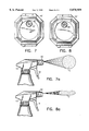
- FIG. 7 is a front view of the nozzle modified to present only the conical spray orifice
- FIG. 7a is a fragmentary side view of the dispenser having the orifice of FIG. 7 and showing the spray and landing pattern, the latter as viewed from a point perpendicular to the landing surface;
- FIG. 8 is a front view of the nozzle modified to present only the fan spray orifice
- FIG. 8a is a fragmentary side view of the dispenser using the orifice of FIG. 8 and showing the spray and landing pattern, the latter as viewed from a point perpendicular to the landing surface;
- FIG. 9 is a perspective view showing that the orifice may be formed in a separate part from the cap.
- FIG. 1 A pump dispenser embodying the invention is shown in FIG. 1 and generally designated 10. It comprises a screw top container 12 having held thereon by an apertured screw cap 14 a pump 16. The pump has a trigger-type actuator 18 and a nozzle 20, all generally conventional.
- the nozzle 20 comprises a body 22 which may be unitarily formed with the lower half of the pump 16.
- the body comprises a tubular section 24 having an enlarged cylindrical head 26.
- the pump means including the downstream check valve is not shown and is not part of this invention.
- the forward part of the head 26 is formed with a pair of opposed generally U-shaped bosses 28 and 30 (FIG. 2) straddling the central opening and spaced from each other by passages 31.
- the upper boss is formed with inward feed channels 32 from the opposite sides of the boss 28. Liquid thus flows from the central opening of the head 26 through passages 31 to the sides of the bosses, into the channels 32 and tangentially into a swirl chamber 34 which serves as a mechanical breakup MBU. Equally offset from the axis of the opening of the head is the outward nib or detent 36 on boss 30.
- the cap 40 completes the assembly.
- the cap 40 may be formed with a number of flat peripheral surfaces to make the cap easy to rotate with the fingers. It will be noted from FIG. 5 that internally the cap 40 is formed with an annular inward wall 42 having an inward annular retainer 44 presenting a forward-facing shoulder 46. When the cap is pushed on in assembly, the head 26 snaps past the lead-in and inward rib 44 and the rear edge of the head 26 engages the shoulder 46 to rotatably connect the cap and body 22.
- the cap 40 is formed also with an inner hub 48 peripherally reduced at 49 to permit communication of the product to the spaces 31 between the bosses 28 and 30.
- the front wall of the cap 40 is formed with a circular frontal recess 50 thus presenting a peripheral rib 52 which guards the structure in the recess.
- the end wall is also formed with diametrically opposite orifices, namely, the conical spray orifice 54 and the fan spray orifice 56 (FIG. 4), each having a chamfered entrance.
- the orifices 54 or 56 is aligned with the 5 swirl chamber 34.
- the other has its chamfer squarely receiving and centered on the detent 36 to hold the cap in proper radial orientation on the head 26.
- the front surface of the bosses 28 and 30 ride sealingly against the inner surface of the front wall of the cap 40.
- the fan spray orifice structure 60 is shown in FIGS. 2, 3 and 4 aligned with the swirl chamber; that is, at the upper portion of the nozzle.
- the structure essentially comprises a pair of parallel ribs 62 which are diagonally disposed and stationed on opposite sides of the orifice.
- these ribs 62 may be formed in a cup-shaped structure 64 surrounding the orifice. Such a cup will protect the ribs 62.
- the angle of the bars with respect to the horizontal has been empirically determined to be in the range of 150° to 350° when the bars extend 0.035 of an inch out from the end of the orifice 34 and are tangent to the orifice. More preferably, the angle is 25°.
- the bars may take other forms. They may be rounded. They may be disposed on a flush surface with the end of the orifice rather than in the cup 64 as shown.
- the anti-drip discharge 70 Shown in FIG. 4 aligned with the swirl chamber 34 is the anti-drip discharge 70.
- This discharge is a spray in the form of a cone having circular landing pattern C (FIG. 7a).
- the orifice structure is in the form of a generally hemispherical cup somewhat flattened adjacent the orifice 54. The axis of the cup is coincident with the axis of the orifice and is of a dimension giving it the capacity of approximately one drop of the liquid product.
- anti-drip structure will be apparent to those who use such a dispenser for dispensing bleach, even a drop of which can ruin a dress; or an oily product which could soil fabric.
- the cup-shaped structure 70 is formed with a widest diameter of 0.125 inch and a curving depth of 0.035", generally hemispherical but slightly flattened as shown.
- FIGS. 7 and 8 are front views of modifications of the nozzle cap in which only a single one of the structures 60, 70 are shown so that the caps 40' and 40" respectively do not selectively provide both the forms of sprays described above.
- the FIG. 7 version provides a cone type spray having a landing pattern shown in FIG. 7a while the FIG. 8 version provides a fan spray. This is assuming that the head 26 inside the cap 40' or 40" has the structure shown in FIGS. 2 and 5.
- FIG. 9 is of interest for its showing of a cap 40 in which the orifice structure 60' is in the form of an insert which fits into a recess 80 in the cap.
- the cap 40 of FIG. 9 may receive any of various inserts 60' to achieve the discharge spray pattern desired.
- the conical spray discharge orifice may be surrounded by a foaming sleeve, as is well known in the art, to provide a foam-type product.
Abstract
Description
Claims (3)
Priority Applications (1)
| Application Number | Priority Date | Filing Date | Title |
|---|---|---|---|
| US08/825,978 US5878959A (en) | 1995-08-16 | 1997-04-04 | Nozzle for pump dispensers |
Applications Claiming Priority (2)
| Application Number | Priority Date | Filing Date | Title |
|---|---|---|---|
| US08/515,881 US5664732A (en) | 1995-08-16 | 1995-08-16 | Nozzle for pump dispensers |
| US08/825,978 US5878959A (en) | 1995-08-16 | 1997-04-04 | Nozzle for pump dispensers |
Related Parent Applications (1)
| Application Number | Title | Priority Date | Filing Date |
|---|---|---|---|
| US08/515,881 Continuation US5664732A (en) | 1995-08-16 | 1995-08-16 | Nozzle for pump dispensers |
Publications (1)
| Publication Number | Publication Date |
|---|---|
| US5878959A true US5878959A (en) | 1999-03-09 |
Family
ID=24053163
Family Applications (2)
| Application Number | Title | Priority Date | Filing Date |
|---|---|---|---|
| US08/515,881 Expired - Fee Related US5664732A (en) | 1995-08-16 | 1995-08-16 | Nozzle for pump dispensers |
| US08/825,978 Expired - Lifetime US5878959A (en) | 1995-08-16 | 1997-04-04 | Nozzle for pump dispensers |
Family Applications Before (1)
| Application Number | Title | Priority Date | Filing Date |
|---|---|---|---|
| US08/515,881 Expired - Fee Related US5664732A (en) | 1995-08-16 | 1995-08-16 | Nozzle for pump dispensers |
Country Status (1)
| Country | Link |
|---|---|
| US (2) | US5664732A (en) |
Cited By (22)
| Publication number | Priority date | Publication date | Assignee | Title |
|---|---|---|---|---|
| USD418755S (en) * | 1998-09-23 | 2000-01-11 | Owens-Illinois Closure Inc. | Dispenser nozzle |
| US6126090A (en) * | 1999-01-12 | 2000-10-03 | Calmar Inc. | Nozzle cap for trigger sprayer |
| US6382527B1 (en) | 2001-01-03 | 2002-05-07 | Owens-Illinois Closure Inc. | Hand-activated dispensing pump having sprayer/foamer selector wheel |
| US6851625B1 (en) * | 2004-03-09 | 2005-02-08 | Roy Kuo | Atomizer with high spraying speeds |
| US7007867B1 (en) | 2005-03-31 | 2006-03-07 | Raoul East Drapeau | Trigger sprayer nozzle providing flow in various directions |
| EP1647333A1 (en) * | 2004-10-13 | 2006-04-19 | Bossini S.p.A. | Shower with fan-like jets |
| CN100344382C (en) * | 2004-03-11 | 2007-10-24 | 康华工业股份有限公司 | Push sprayer with liquid injecting speed-enhancing function |
| US20090032610A1 (en) * | 2007-07-30 | 2009-02-05 | Michael Scot Rosko | Anti-Drip fluid delivery device |
| US20090314856A1 (en) * | 2008-06-18 | 2009-12-24 | Polytop Corporation | Fan orifice dispensing closure |
| US20100237159A1 (en) * | 2009-03-19 | 2010-09-23 | Prater Rodney L | Nozzle assembly for liquid dispenser |
| USD650046S1 (en) | 2011-03-01 | 2011-12-06 | Smg Brands, Inc. | Sprayer |
| US20110303768A1 (en) * | 2010-06-14 | 2011-12-15 | Valois S.A.S. | Fluid dispenser head |
| USD670982S1 (en) | 2011-03-01 | 2012-11-20 | Smg Brands, Inc. | Applicator |
| USD681470S1 (en) | 2010-01-08 | 2013-05-07 | Oms Investments, Inc. | Dispensing container |
| US20130119157A1 (en) * | 2010-06-09 | 2013-05-16 | Guala Dispensing S.P.A. | Dispensing Device For A Liquid With Multifunction Nozzle |
| USD708301S1 (en) | 2013-03-15 | 2014-07-01 | Oms Investments, Inc. | Liquid sprayer |
| US8814010B2 (en) | 2008-06-18 | 2014-08-26 | Mwv Slatersville, Llc | Fan orifice dispensing closure |
| US9980430B2 (en) | 2011-03-01 | 2018-05-29 | Oms Investments, Inc. | Ready-to-use hose end sprayer |
| US10022742B2 (en) | 2011-03-01 | 2018-07-17 | Oms Investments, Inc. | Applicator with collapsible wand |
| US10155232B2 (en) | 2011-04-19 | 2018-12-18 | Dlhbowles, Inc. | Cup-shaped fluidic circuit, nozzle assembly and method |
| US10549289B2 (en) | 2008-06-18 | 2020-02-04 | Silgan Dispensing Systems Slatersville, Llc | Fan orifice dispensing closure |
| USD956175S1 (en) * | 2020-11-11 | 2022-06-28 | Precision Valve Corporation | Actuator orifice |
Families Citing this family (18)
| Publication number | Priority date | Publication date | Assignee | Title |
|---|---|---|---|---|
| WO2000012179A1 (en) * | 1998-08-27 | 2000-03-09 | Bowles Fluidics Corporation | Water bottle with drinking and spray modes |
| US6027042A (en) * | 1998-10-13 | 2000-02-22 | Summit Packaging Systems, Inc. | Actuator assembly with variable spray pattern |
| US7021571B1 (en) * | 1999-06-07 | 2006-04-04 | The Procter & Gamble Company | Spray device with flat fan nozzle |
| US6547166B1 (en) * | 2000-08-11 | 2003-04-15 | L.R. Nelson Corporation | Pattern adjustable flow nozzle |
| US6446882B1 (en) | 2001-02-02 | 2002-09-10 | Owens-Illinois Closure Inc. | Trigger sprayer having sprayer/foamer selector nozzle cap |
| US7036689B1 (en) | 2002-04-22 | 2006-05-02 | Continental Afa Dispensing Company | Child-resistant trigger sprayer |
| US6997397B1 (en) | 2003-04-08 | 2006-02-14 | Continental Afa Dispensing Company | Trigger sprayer nozzle |
| FR2858567B1 (en) * | 2003-08-04 | 2006-03-03 | Valois Sas | FLUID SPRAY HEAD |
| US9242256B2 (en) | 2007-07-17 | 2016-01-26 | S.C. Johnson & Son, Inc. | Aerosol dispenser assembly having VOC-free propellant and dispensing mechanism therefor |
| DE202008009601U1 (en) * | 2008-05-15 | 2009-09-24 | Seaquist Perfect Dispensing Gmbh | Spray head and device for dispensing a liquid |
| IT1397485B1 (en) | 2010-01-15 | 2013-01-16 | Guala Dispensing Spa | DISTRIBUTION DEVICE FOR A LIQUID WITH MULTIFUNCTIONAL NOZZLE |
| US20110180101A1 (en) * | 2010-01-25 | 2011-07-28 | The Dial Corporation | Multi-surface acidic bathroom cleaning system |
| US20110180100A1 (en) * | 2010-01-25 | 2011-07-28 | The Dial Corporation | Multi-surface kitchen cleaning system |
| PT3122852T (en) | 2014-03-28 | 2021-03-15 | Fater Spa | Cleaning system comprising a sprayer bottle and a cleaning composition |
| US10265708B2 (en) * | 2014-07-15 | 2019-04-23 | Lunatec, Inc. | Pressurizable fluid container and flexible dispenser |
| EP4292629A3 (en) * | 2014-09-04 | 2024-03-20 | Octet Medical, Inc. | Electrostatic fluid delivery system |
| USD749692S1 (en) * | 2014-10-08 | 2016-02-16 | PSI Pressure Systems Corp. | Nozzle |
| GB2542401B (en) * | 2015-09-18 | 2018-12-12 | Reckitt Benckiser Brands Ltd | Modified spray head |
Citations (6)
| Publication number | Priority date | Publication date | Assignee | Title |
|---|---|---|---|---|
| US3797749A (en) * | 1971-09-08 | 1974-03-19 | T Tada | Sprayer |
| US4220285A (en) * | 1976-10-18 | 1980-09-02 | Spray Plast S.r.1 | Hand sprayer for liquids |
| US4646969A (en) * | 1982-11-19 | 1987-03-03 | Ceskoslovenska Akademie Ved | Double acting mechanical pump liquid atomizer |
| US4883227A (en) * | 1986-01-10 | 1989-11-28 | Afa Products, Inc. | Foamer nozzle assembly with air passageway |
| JPH04322759A (en) * | 1991-04-24 | 1992-11-12 | Matsushita Electric Works Ltd | Spray nozzle |
| US5687877A (en) * | 1995-11-03 | 1997-11-18 | Owens-Illinois Closure Inc. | Pump dispenser having moveable outlet check valve element |
Family Cites Families (9)
| Publication number | Priority date | Publication date | Assignee | Title |
|---|---|---|---|---|
| US2172193A (en) * | 1936-10-15 | 1939-09-05 | Eclipse Air Brush Company Inc | Device for spraying paint and the like and nozzle therefor |
| US3054563A (en) * | 1959-07-29 | 1962-09-18 | William F Steinen | Flat spray atomizing nozzle |
| US3398899A (en) * | 1966-06-23 | 1968-08-27 | Ferro Corp | Nozzle applicator for dry process enamels |
| US3711029A (en) * | 1971-04-13 | 1973-01-16 | L Bartlett | Spray nozzle |
| CA1005404A (en) * | 1973-08-29 | 1977-02-15 | Thomas J. Smrt | Actuator for aerosol can valve |
| US4109869A (en) * | 1977-06-16 | 1978-08-29 | Dutton-Lainson Company | Oiler with adjustable spray nozzle |
| US4730775A (en) * | 1986-01-10 | 1988-03-15 | Afa Division Of Waynesboro Textiles, Inc. | Two piece foamer nozzle assembly |
| IT1243896B (en) * | 1990-11-06 | 1994-06-28 | Coster Tecnologie Speciali Spa | PUMP DEVICE FOR DOSING OR DISPENSING HAND-OPERATED FLUIDS. |
| JP3090338B2 (en) * | 1991-03-13 | 2000-09-18 | 松下電工株式会社 | Spray nozzle |
-
1995
- 1995-08-16 US US08/515,881 patent/US5664732A/en not_active Expired - Fee Related
-
1997
- 1997-04-04 US US08/825,978 patent/US5878959A/en not_active Expired - Lifetime
Patent Citations (6)
| Publication number | Priority date | Publication date | Assignee | Title |
|---|---|---|---|---|
| US3797749A (en) * | 1971-09-08 | 1974-03-19 | T Tada | Sprayer |
| US4220285A (en) * | 1976-10-18 | 1980-09-02 | Spray Plast S.r.1 | Hand sprayer for liquids |
| US4646969A (en) * | 1982-11-19 | 1987-03-03 | Ceskoslovenska Akademie Ved | Double acting mechanical pump liquid atomizer |
| US4883227A (en) * | 1986-01-10 | 1989-11-28 | Afa Products, Inc. | Foamer nozzle assembly with air passageway |
| JPH04322759A (en) * | 1991-04-24 | 1992-11-12 | Matsushita Electric Works Ltd | Spray nozzle |
| US5687877A (en) * | 1995-11-03 | 1997-11-18 | Owens-Illinois Closure Inc. | Pump dispenser having moveable outlet check valve element |
Cited By (38)
| Publication number | Priority date | Publication date | Assignee | Title |
|---|---|---|---|---|
| USD418755S (en) * | 1998-09-23 | 2000-01-11 | Owens-Illinois Closure Inc. | Dispenser nozzle |
| US6126090A (en) * | 1999-01-12 | 2000-10-03 | Calmar Inc. | Nozzle cap for trigger sprayer |
| US6382527B1 (en) | 2001-01-03 | 2002-05-07 | Owens-Illinois Closure Inc. | Hand-activated dispensing pump having sprayer/foamer selector wheel |
| US6536686B2 (en) * | 2001-01-03 | 2003-03-25 | Owens-Illinois Closure Inc. | Hand activated dispensing pump having sprayer/foamer selector wheel |
| US6851625B1 (en) * | 2004-03-09 | 2005-02-08 | Roy Kuo | Atomizer with high spraying speeds |
| CN100344382C (en) * | 2004-03-11 | 2007-10-24 | 康华工业股份有限公司 | Push sprayer with liquid injecting speed-enhancing function |
| EP1647333A1 (en) * | 2004-10-13 | 2006-04-19 | Bossini S.p.A. | Shower with fan-like jets |
| US7007867B1 (en) | 2005-03-31 | 2006-03-07 | Raoul East Drapeau | Trigger sprayer nozzle providing flow in various directions |
| US20090032610A1 (en) * | 2007-07-30 | 2009-02-05 | Michael Scot Rosko | Anti-Drip fluid delivery device |
| US20090314856A1 (en) * | 2008-06-18 | 2009-12-24 | Polytop Corporation | Fan orifice dispensing closure |
| US8469241B2 (en) | 2008-06-18 | 2013-06-25 | Mwv Slatersville, Llc | Fan orifice dispensing closure |
| US10940494B2 (en) | 2008-06-18 | 2021-03-09 | Silgan Dispensing Systems Slatersville Llc | Fan orifice dispensing closure |
| US9079198B2 (en) | 2008-06-18 | 2015-07-14 | Mwv Slatersville, Llc | Fan orifice dispensing closure |
| US10549289B2 (en) | 2008-06-18 | 2020-02-04 | Silgan Dispensing Systems Slatersville, Llc | Fan orifice dispensing closure |
| US8814010B2 (en) | 2008-06-18 | 2014-08-26 | Mwv Slatersville, Llc | Fan orifice dispensing closure |
| US10406536B2 (en) | 2008-06-18 | 2019-09-10 | Silgan Dispensing Systems Slatersville Llc | Fan orifice dispensing closure |
| US20100237159A1 (en) * | 2009-03-19 | 2010-09-23 | Prater Rodney L | Nozzle assembly for liquid dispenser |
| US8844841B2 (en) | 2009-03-19 | 2014-09-30 | S.C. Johnson & Son, Inc. | Nozzle assembly for liquid dispenser |
| USD681470S1 (en) | 2010-01-08 | 2013-05-07 | Oms Investments, Inc. | Dispensing container |
| US20130119157A1 (en) * | 2010-06-09 | 2013-05-16 | Guala Dispensing S.P.A. | Dispensing Device For A Liquid With Multifunction Nozzle |
| US9409194B2 (en) * | 2010-06-09 | 2016-08-09 | Guala Dispensing S.P.A. | Dispensing device for a liquid with multifunction nozzle |
| US8690081B2 (en) * | 2010-06-14 | 2014-04-08 | Aptar France Sas | Fluid dispenser head |
| US20110303768A1 (en) * | 2010-06-14 | 2011-12-15 | Valois S.A.S. | Fluid dispenser head |
| US10022742B2 (en) | 2011-03-01 | 2018-07-17 | Oms Investments, Inc. | Applicator with collapsible wand |
| USD650046S1 (en) | 2011-03-01 | 2011-12-06 | Smg Brands, Inc. | Sprayer |
| USD797529S1 (en) | 2011-03-01 | 2017-09-19 | Oms Investments, Inc. | Applicator |
| US9980430B2 (en) | 2011-03-01 | 2018-05-29 | Oms Investments, Inc. | Ready-to-use hose end sprayer |
| USD736577S1 (en) | 2011-03-01 | 2015-08-18 | Oms Investments, Inc. | Applicator |
| USD999033S1 (en) | 2011-03-01 | 2023-09-19 | Oms Investments, Inc. | Applicator |
| USD852593S1 (en) | 2011-03-01 | 2019-07-02 | Oms Investments, Inc. | Applicator |
| US11744171B2 (en) | 2011-03-01 | 2023-09-05 | Oms Investments, Inc. | Ready-to-use hose end sprayer |
| USD864679S1 (en) | 2011-03-01 | 2019-10-29 | Oms Investments, Inc. | Applicator |
| USD670982S1 (en) | 2011-03-01 | 2012-11-20 | Smg Brands, Inc. | Applicator |
| USD779898S1 (en) | 2011-03-01 | 2017-02-28 | Oms Investments, Inc. | Applicator |
| US11338313B2 (en) | 2011-03-01 | 2022-05-24 | Oms Investments, Inc. | Applicator with collapsible wand |
| US10155232B2 (en) | 2011-04-19 | 2018-12-18 | Dlhbowles, Inc. | Cup-shaped fluidic circuit, nozzle assembly and method |
| USD708301S1 (en) | 2013-03-15 | 2014-07-01 | Oms Investments, Inc. | Liquid sprayer |
| USD956175S1 (en) * | 2020-11-11 | 2022-06-28 | Precision Valve Corporation | Actuator orifice |
Also Published As
| Publication number | Publication date |
|---|---|
| US5664732A (en) | 1997-09-09 |
Similar Documents
| Publication | Publication Date | Title |
|---|---|---|
| US5878959A (en) | Nozzle for pump dispensers | |
| EP0436610B1 (en) | Foam nozzle assembly | |
| US6715698B2 (en) | Manually operable trigger sprayer with rearwardly located sprayer valve | |
| KR100504082B1 (en) | Manual Pump Sprayer | |
| JP3219362B2 (en) | Pump sprayer | |
| US5397060A (en) | Foam-spray-off trigger sprayer | |
| EP2181771B1 (en) | Dome pump spray assembly | |
| JPS62216659A (en) | Two-piece foaming nozzle assembly | |
| EP0505571B1 (en) | Foaming nozzle to be mounted to an atomizer | |
| EP1301404B1 (en) | Variable discharge dispensing head for a squeeze dispenser | |
| US4669665A (en) | Nozzle | |
| US5366160A (en) | Foamer nozzle with looped rib flow disrupters | |
| JP3449962B2 (en) | Container with dispenser head | |
| US6536686B2 (en) | Hand activated dispensing pump having sprayer/foamer selector wheel | |
| US3570770A (en) | Valve button | |
| US3838822A (en) | Valve button | |
| US3711031A (en) | Valve button | |
| JP3490562B2 (en) | Manual pump type foam discharger | |
| JP2520340B2 (en) | Fluid ejection device | |
| JP2008502475A (en) | Dispensing device | |
| JPH04363162A (en) | Forming nozzle for fitting atomizer | |
| AU625077C (en) | Foam-off nozzle assembly with barrel screen insert for use in a trigger sprayer | |
| JPH0335385Y2 (en) | ||
| MXPA97001437A (en) | Spray nozzle with pump to produce solid aspers unpatron | |
| MXPA95004420A (en) | Sprayer who has a variable spray pattern |
Legal Events
| Date | Code | Title | Description |
|---|---|---|---|
| STCF | Information on status: patent grant |
Free format text: PATENTED CASE |
|
| FPAY | Fee payment |
Year of fee payment: 4 |
|
| AS | Assignment |
Owner name: CONTINENTALAFA DISPENSING COMPANY, MISSOURI Free format text: CORRECTIV;ASSIGNOR:OWENS ILLINOIS CLOSURE, INC.;REEL/FRAME:015886/0892 Effective date: 20031107 |
|
| AS | Assignment |
Owner name: OAK HILL SECURITIES FUND, L.P., NEW YORK Free format text: ASSIGNMENT FOR SECURITY;ASSIGNORS:CONTINENTALAFA DISPENSING COMPANY;AFA PRODUCTS INC.;CONTINENTAL SPRAYERS INTERNATIONAL INC.;AND OTHERS;REEL/FRAME:014146/0907 Effective date: 20031112 Owner name: OAK HILL SECURITIES FUND, L.P.,NEW YORK Free format text: ASSIGNMENT FOR SECURITY;ASSIGNORS:CONTINENTALAFA DISPENSING COMPANY;AFA PRODUCTS INC.;CONTINENTAL SPRAYERS INTERNATIONAL INC.;AND OTHERS;REEL/FRAME:014146/0907 Effective date: 20031112 |
|
| AS | Assignment |
Owner name: CONTINENTALAFA DISPENSING COMPANY,MISSOURI Free format text: TERMINATION OF SECURITY INTEREST AND RELEASE OF CO;ASSIGNOR:OAK HILL SECURITIES FUND, L.P.;REEL/FRAME:019331/0617 Effective date: 20050715 Owner name: AFA PRODUCTS, INC., DELAWARE CORPORATION,NORTH CAR Free format text: TERMINATION OF SECURITY INTEREST AND RELEASE OF CO;ASSIGNOR:OAK HILL SECURITIES FUND, L.P.;REEL/FRAME:019331/0617 Effective date: 20050715 Owner name: AFA PRODUCTS, INC., DELAWARE CORPORATION, NORTH CA Free format text: TERMINATION OF SECURITY INTEREST AND RELEASE OF CO;ASSIGNOR:OAK HILL SECURITIES FUND, L.P.;REEL/FRAME:019331/0617 Effective date: 20050715 Owner name: CONTINENTAL SPRAYERS INTERNATIONAL, INC., A DELAWA Free format text: TERMINATION OF SECURITY INTEREST AND RELEASE OF CO;ASSIGNOR:OAK HILL SECURITIES FUND, L.P.;REEL/FRAME:019331/0617 Effective date: 20050715 Owner name: CONTINENTALAFA DISPENSING COMPANY, MISSOURI Free format text: TERMINATION OF SECURITY INTEREST AND RELEASE OF CO;ASSIGNOR:OAK HILL SECURITIES FUND, L.P.;REEL/FRAME:019331/0617 Effective date: 20050715 |
|
| AS | Assignment |
Owner name: THE CIT GROUP/BUSINESS CREDIT, INC. AS COLLATERAL Free format text: SECURITY AGREEMENT;ASSIGNOR:CONTINENTALAFA DISPENSING COMPANY;REEL/FRAME:016722/0012 Effective date: 20050715 |
|
| AS | Assignment |
Owner name: THE CIT GROUP/BUSINESS CREDIT, INC. AS COLLATERAL Free format text: SECURITY AGREEMENT;ASSIGNOR:CONTINENTALAFA DISPENSING COMPANY;REEL/FRAME:016722/0349 Effective date: 20050715 |
|
| AS | Assignment |
Owner name: OWENS-ILLINOIS CLOSURE INC., OHIO Free format text: ASSIGNMENT OF ASSIGNORS INTEREST;ASSIGNORS:CONTAXIS, III, WILLIAM;SMOLEN, JR., RICHARD J.;REEL/FRAME:016793/0397;SIGNING DATES FROM 19950630 TO 19950809 |
|
| FPAY | Fee payment |
Year of fee payment: 8 |
|
| AS | Assignment |
Owner name: CONTINENTALAFA DISPENSING COMPANY,MISSOURI Free format text: RELEASE OF SECURITY INTEREST IN PATENTS AS RECORDED ON 11/2/2005 AT REEL 016722, FRAME 0012 AND ON 11/3/2005 REEL 016722, FRAME 0349;ASSIGNOR:THE CIT GROUP/ BUSINESS CREDIT, INC;REEL/FRAME:019362/0565 Effective date: 20070515 Owner name: CONTINENTALAFA DISPENSING COMPANY, MISSOURI Free format text: RELEASE OF SECURITY INTEREST IN PATENTS AS RECORDED ON 11/2/2005 AT REEL 016722, FRAME 0012 AND ON 11/3/2005 REEL 016722, FRAME 0349;ASSIGNOR:THE CIT GROUP/ BUSINESS CREDIT, INC;REEL/FRAME:019362/0565 Effective date: 20070515 |
|
| AS | Assignment |
Owner name: WACHOVIA CAPITAL FINANCE CORPORATION (CENTRAL),ILL Free format text: SECURITY AGREEMENT;ASSIGNOR:CONTINENTALAFA DISPENSING COMPANY;REEL/FRAME:019399/0087 Effective date: 20070515 Owner name: WACHOVIA CAPITAL FINANCE CORPORATION (CENTRAL), IL Free format text: SECURITY AGREEMENT;ASSIGNOR:CONTINENTALAFA DISPENSING COMPANY;REEL/FRAME:019399/0087 Effective date: 20070515 |
|
| AS | Assignment |
Owner name: HARBINGER CAPITAL PARTNERS MASTER FUND I, LTD.,NEW Free format text: PATENT COLLATERAL ASSIGNMENT AND SECURITY AGREEMENT;ASSIGNOR:CONTINENTALAFA DISPENSING COMPANY;REEL/FRAME:019432/0235 Effective date: 20070515 Owner name: HARBINGER CAPITAL PARTNERS MASTER FUND I, LTD., NE Free format text: PATENT COLLATERAL ASSIGNMENT AND SECURITY AGREEMENT;ASSIGNOR:CONTINENTALAFA DISPENSING COMPANY;REEL/FRAME:019432/0235 Effective date: 20070515 |
|
| FPAY | Fee payment |
Year of fee payment: 12 |
|
| AS | Assignment |
Owner name: CONTINENTALAFA DISPENSING COMPANY, VIRGINIA Free format text: RELEASE BY SECURED PARTY;ASSIGNOR:WACHOVIA CAPITAL FINANCE CORPORATION (CENTRAL);REEL/FRAME:041511/0463 Effective date: 20081016 |
|
| AS | Assignment |
Owner name: CONTINENTALAFA DISPENSING COMPANY, VIRGINIA Free format text: RELEASE BY SECURED PARTY;ASSIGNOR:HARBINGER CAPITAL PARTNERS MASTER FUND I, LTD.;REEL/FRAME:041518/0304 Effective date: 20081015 |