US5808573A - Methods and structure for sampled-data timing recovery with reduced complexity and latency - Google Patents
Methods and structure for sampled-data timing recovery with reduced complexity and latency Download PDFInfo
- Publication number
- US5808573A US5808573A US08/695,327 US69532796A US5808573A US 5808573 A US5808573 A US 5808573A US 69532796 A US69532796 A US 69532796A US 5808573 A US5808573 A US 5808573A
- Authority
- US
- United States
- Prior art keywords
- signal
- input signal
- digital
- analog
- timing
- Prior art date
- Legal status (The legal status is an assumption and is not a legal conclusion. Google has not performed a legal analysis and makes no representation as to the accuracy of the status listed.)
- Expired - Lifetime
Links
Images


Classifications
-
- G—PHYSICS
- G11—INFORMATION STORAGE
- G11B—INFORMATION STORAGE BASED ON RELATIVE MOVEMENT BETWEEN RECORD CARRIER AND TRANSDUCER
- G11B20/00—Signal processing not specific to the method of recording or reproducing; Circuits therefor
- G11B20/10—Digital recording or reproducing
- G11B20/10009—Improvement or modification of read or write signals
- G11B20/10046—Improvement or modification of read or write signals filtering or equalising, e.g. setting the tap weights of an FIR filter
- G11B20/10055—Improvement or modification of read or write signals filtering or equalising, e.g. setting the tap weights of an FIR filter using partial response filtering when writing the signal to the medium or reading it therefrom
-
- G—PHYSICS
- G11—INFORMATION STORAGE
- G11B—INFORMATION STORAGE BASED ON RELATIVE MOVEMENT BETWEEN RECORD CARRIER AND TRANSDUCER
- G11B20/00—Signal processing not specific to the method of recording or reproducing; Circuits therefor
- G11B20/10—Digital recording or reproducing
- G11B20/14—Digital recording or reproducing using self-clocking codes
- G11B20/1403—Digital recording or reproducing using self-clocking codes characterised by the use of two levels
-
- H—ELECTRICITY
- H03—ELECTRONIC CIRCUITRY
- H03M—CODING; DECODING; CODE CONVERSION IN GENERAL
- H03M1/00—Analogue/digital conversion; Digital/analogue conversion
- H03M1/06—Continuously compensating for, or preventing, undesired influence of physical parameters
- H03M1/08—Continuously compensating for, or preventing, undesired influence of physical parameters of noise
- H03M1/0836—Continuously compensating for, or preventing, undesired influence of physical parameters of noise of phase error, e.g. jitter
-
- H—ELECTRICITY
- H03—ELECTRONIC CIRCUITRY
- H03M—CODING; DECODING; CODE CONVERSION IN GENERAL
- H03M1/00—Analogue/digital conversion; Digital/analogue conversion
- H03M1/12—Analogue/digital converters
-
- H—ELECTRICITY
- H04—ELECTRIC COMMUNICATION TECHNIQUE
- H04L—TRANSMISSION OF DIGITAL INFORMATION, e.g. TELEGRAPHIC COMMUNICATION
- H04L7/00—Arrangements for synchronising receiver with transmitter
- H04L7/04—Speed or phase control by synchronisation signals
- H04L7/041—Speed or phase control by synchronisation signals using special codes as synchronising signal
- H04L7/046—Speed or phase control by synchronisation signals using special codes as synchronising signal using a dotting sequence
Definitions
- This invention relates to methods and structure for recovering the sampling clock and controlling the gain of a sampled-data receiver from a signal. More specifically, this invention relates to methods and structure for partitioning output bits from an analog-to-digital converter (ADC) in a way that simplifies the phase error and the gain error calculations so as to reduce the complexity of the circuits needed to implement both the phase-locked-loop (PLL) that is used to recover the sampling clock and the automatic gain control (AGC) function.
- ADC analog-to-digital converter
- Digital magnetic and optical storage applications involve the recording of digital sequences onto the media and the retrieval of such sequences from an analog signal, sensed by a readback head and corrupted by noise, interference, and distortion.
- the fundamental design goal is to achieve the highest recording density per unit area while maintaining an acceptable probability of error between the recorded and the retrieved sequences.
- read/write channels use a combination of coding and equalization approaches. Each of these functions are reviewed below.
- Digital magnetic and optical storage devices use RLL codes to improve signal detectability or to insure frequent updates to the timing and gain loops, or both.
- the RLL codes are generally characterized by two parameters, d and k, which control, respectively, the minimum and the maximum number of symbol intervals between successive transitions in the binary input signal. For a given value of d, the RLL code insures that there are at least (d+1), and at most (k+1), symbol intervals between successive transitions.
- Commonly used codes in magnetic and optical storage products include codes with (d,k) constraints of (1,7) and (2,7). These codes are typically used with Peak Detection methods. Peak detection methods are asynchronous and involve the detection of single pulses.
- the k constraint insures that a non-zero channel output is produced with some minimum frequency to maintain robust operation of timing and gain loops.
- the d constraint helps signal detectability with peak detection.
- PRML Partial Response Maximum Likelihood
- ISI intersymbol interference
- the readback signal is first equalized to a prescribed Partial Response (PR) signal.
- PR signals have the feature that allows for controlled overlap (or interference) of responses in the output signal due to successive input symbols.
- the a priori knowledge of the controlled ISI after the equalizer results in a significant reduction in the complexity of the required detector relative to the detector required for the unequalized signal.
- readback signal 104 from head/media/preamp 102 is sent to equalizer 106.
- Equalizer 106 also known as the PRML receiver, equalizes readback signal 104 to create equalized signal 108 which is a suitable PR signal.
- This PR signal is commonly referred to as "Class IV PR" or modified duobinary signaling.
- Equalized signal 108 is then detected using a sequence detector such as Viterbi Detector 110, which is based on the Viterbi Algorithm.
- a sequence detector such as Viterbi Detector 110, which is based on the Viterbi Algorithm.
- PRML Partial Response Maximum-Likelihood
- the choice of the PR target signal is not unique, but dictated by the operating linear density.
- phase locked loop PLL
- ADC analog to digital converter
- phase error detector 210 When the phase of the input signal and the phase of the oscillator diverge (due to, for example, noise and/or variation of disk rotation speed), the phase error becomes non-zero.
- a non-zero phase error causes digital phase error detector 210 to send a signal to charge pump 215 which outputs a current proportional to the phase error.
- the current from charge pump 215 is converted to a voltage by loop filter 235.
- the voltage shifts the frequency of VCO 220 to match phase with the input signal.
- Timing recovery methods for synchronous data receivers have been investigated by K. H. Mueller and M. Muller, "Timing recovery in digital synchronous data receivers," IEEE Trans. Commun., vol. COM-24, pp. 516-530, May 1976 which is incorporated herein by reference.
- PRML it has been proposed by F. Dolivo, W. Schott, and G. Ungerboeck, "Fast timing recovery for partial response signaling systems," Int. Conf. Commun. '89, ICC'89, Boston, Mass., June 1989 (incorporated herein by reference) to update the timing-phase at time instant nT using the timing gradient:
- y n is the sampled value and x n is the ideal sample value that is closest to y n .
- x n is restricted to take the values +1, 0, or -1.
- a second order PLL is used to recover the sampling clock.
- the PLL operation is divided into two stages, acquisition and tracking. During acquisition, a sine wave with frequency equal to one quarter of the sampling frequency (i.e. having a period of 4T where T is the sampling interval) is used to provide the frequency and phase references for the PLL.
- the sine wave is written onto the disk, usually at the start of each track and is known as the preamble. Following the preamble on the disk is the user data which is sampled in tracking mode.
- Preamble 310 is read during the acquisition and data 320 is read during the tracking mode. Since the sampling clock should be at the ideal sampling frequency and phase after acquisition, the PLL bandwidth is lowered in the tracking mode to reduce timing jitter.
- VGA variable gain amplifier
- AGC automatic gain control
- Feedback loop 445 serves to control VGA 420 during analog acquisition.
- the equalized signal is digitized in analog-to-digital converter (ADC) 440.
- ADC analog-to-digital converter
- the digitized signal is sent to digital gain error detector 410.
- An appropriate signal is sent from digital gain error detector 410 to VGA 420 to update the gain of the signal.
- FIG. 4b shows a three stage AGC function which utilizes both analog acquisition mode 460 and digital acquisition mode 470 with preamble 455.
- Digital tracking mode 480 is engaged prior to the end of preamble 455 to ensure that data is properly tracked upon receipt.
- AGC functions for PRML channels have been proposed that update the VGA gain by using the gradient:
- y n is the sampled value
- x n is the ideal sample value that is closest to y n
- e n is the decision error.
- x n is either +1, -1 or 0 for PR4.
- EPRML channels have also been investigated previously. These invariably include an additional signal processing block after the conventional PR4 Viterbi detector to achieve the improved performance of EPRML without modifying the AGC loop.
- EPRML relaxes the need for significant equalization and the EPRML detector can generally tolerate poorer high frequency signal-to-noise ratio (SNR) from the recording channel. EPRML can therefore operate at higher linear densities than PRML. However, implementation of EPRML has been hindered by the added complexity of the circuitry that is required which leads to longer processing times and lower data throughput rates.
- SNR signal-to-noise ratio
- the invention relates to methods and structure for recovering the sampling clock and for controlling the gain of a sampled-data receiver.
- EPRML channel is by nature a synchronous detection channel and thus requires sampling of the read signal in proper amplitude, frequency and phase.
- a clock recovery algorithm is employed for an EPRML channel. Samples which are equalized to EPR4 are used to derive the timing gradient without going through PR4 as an intermediate step.
- the circuit architecture embeds the implementation of the phase error calculations in the analog-to-digital converter (ADC) to simplify the overall circuit implementation.
- the bit slices in the analog-to-digital converter (ADC) sample the data input signal, the data input signal being encoded into an ideal sample value closest to the data input signal and a decision error.
- the sampled reference output signals of the comparators are used to directly drive a phase error digital-to-analog converter without additional signal processing for the acquisition mode.
- phase error digital-to-analog converter provides a control signal to the timing circuit.
- Embodiments of this invention may be implemented in a number of technologies; for example, bipolar, CMOS or gallium arsenide technologies may be used in accordance with this invention.
- Samples are equalized to EPR4 to derive the gain error by utilizing a gain control algorithm for an EPRML channel without going through PR4 as an intermediate step.
- the circuit architecture embeds the implementation of the gain error calculations in the ADC to simplify the overall circuit implementation.
- An intermediate stage is introduced between the analog continuous-time acquisition mode and the digital discrete-time tracking mode.
- the intermediate digital discrete-time acquisition mode compensates for potential mismatches between the voltage reference of the analog acquisition loop and the voltage reference of the ADC during the digital tracking loop.
- Both the gain digital discrete-time acquisition mode and the gain digital discrete-time tracking mode use the input signal encoded into the ideal signal sample value and the decision error.
- the ideal signal sample value and the decision error in one embodiment are represented by three (3) bits each.
- Calculations for phase error and gain error performed in the circuit in one embodiment use the sign of the ideal signal sample value in place of the ideal sample signal value.
- the result of the phase error and the gain error is converted into a positive or negative current to drive the respective loop filters for the timing and gain circuits.
- the use of a current to control the timing and gain circuits is merely one embodiment and other control signals are possible.
- the present invention allows simplified circuitry and therefore assists in making a single chip implementation of EPRML feasible.
- the circuitry of this invention is also faster than prior art circuitry.
- FIG. 1 shows a typical PRML block diagram.
- FIG. 2 shows a typical phase lock loop block diagram.
- FIG. 3 shows the operation of a phase lock loop system.
- FIG. 4a shows a typical automatic gain control block diagram.
- FIG. 4b shows a three stage AGC function.
- FIG. 5 shows the acquisition timing and gain sample points for EPRML.
- FIG. 6 shows a combined phase lock loop and automatic gain control block diagram in accordance with an embodiment of this invention.
- FIG. 7 shows a simplified flash analog to digital converter.
- FIG. 8 shows the relationships of comparator values (CMP), analog to digital converter (ADC) thresholds and thermometer code levels.
- FIG. 9 shows the portion of the ADC used during acquisition in accordance with an embodiment of this invention.
- FIG. 10a shows the one-to-one mapping of the thermometer code levels to (x,e) format.
- FIG. 10b shows an embodiment of the one-to one mapping of the thermometer code levels to provide the e(0) bit of e using a wide OR gate.
- FIG. 10c shows an embodiment of the encoding of the thermometer code levels to provide the e(1) bit of e using a wide OR gate.
- FIG. 10d shows an embodiment of the encoding of the thermometer code levels to provide the e(2) bit of e using a wide OR gate.
- FIG. 10e shows an embodiment of the encoding of the thermometer code levels to provide the x(0) bit of x using a wide OR gate.
- FIG. 10f shows an embodiment of the encoding of the thermometer code levels to provide the x(1) bit of x using a wide OR gate.
- FIG. 10g shows an embodiment of the encoding of the thermometer code levels to provide the x(2) bit of x using a wide OR gate.
- FIG. 11a shows ADC slices 20-27 and Timing ACQ's P1-P8 for timing acquisition in accordance with an embodiment of this invention.
- FIG. 11b shows ADC slice 19 and Timing ACQ CO for timing acquisition in accordance with an embodiment of this invention.
- FIG. 11c shows ADC slices 11-18 and Timing ACQ's N1-N8 for timing acquisition in accordance with an embodiment of this invention.
- FIG. 12 shows the preamble and timing signals used during acquisition in accordance with an embodiment of this invention.
- FIG. 13 shows a timing tracking mode phase detector block diagram in accordance with an embodiment of this invention.
- FIG. 14 shows an analog acquisition mode gain detector block diagram in accordance with an embodiment of this invention.
- FIG. 15 shows a digital acquisition mode gain detector block diagram in accordance with an embodiment of this invention.
- FIG. 16 shows a digital tracking mode gain detector block diagram in accordance with an embodiment of this invention.
- phase-locked-loop PLL
- AGC automatic gain control
- An improved phase error calculation and an improved gain error calculation are described for the EPR4 target.
- a zero-phase restart is used to start the clock at a "0" crossing of the 4T sine wave preamble.
- the object of the timing loop during acquisition is to adjust the timing clock such that samples are taken at "0" crossings of the sine wave preamble.
- the timing gradient used for EPRML is:
- y n is the sampled value
- x n (which in EPRML can take one of 5 possible values: +2, +1, 0, -1, -2) is the ideal sample value that is closest to y n
- e n is the decision error
- sign x n ! function is defined by
- a three stage AGC operation as shown in FIG. 4b is used for compensating for circuit mismatches between the analog continuous-time acquisition mode and the digital discrete-time tracking mode. To ensure that data is properly tracked upon receipt, digital tracking begins during the preamble.
- the acquisition PLL timing and acquisition AGC modes are effectively decoupled from each other once the gain and phase are close to their ideal values since the acquisition PLL loop is dependent on the "0" crossings of the sine wave preamble while the acquisition AGC loop is dependent on the peaks of the sine wave preamble.
- the PLL circuit uses the "0" crossings t to provide timing information while the +-"2" peaks g are used by the AGC loop for gain information, thereby allowing time 2T for timing and gain signal processing during acquisition.
- orthogonality is maintained due to the locking of the PLL and every sample value is used in both the tracking AGC and PLL circuits. Therefore, the phase and gain recovery loops provide simultaneous tracking of correct system gain and clock.
- FIG. 6 is a block diagram of one embodiment of the combined ADC/timing and ADC/gain architecture.
- An analog read signal on lead 601 is applied to a variable gain amplifier (VGA) 605.
- VGA output signal on lead 606 is sent to ER (Equalized Receiver) filter block 610.
- ER filter block 610 Details on the optimal setting for ER filter block 610 are provided in the patent application "Method and Apparatus for Adaptively Processing the Readback Signal in a Read Channel Device for Digital Storage," incorporated herein by reference, filed on the same day as this application and assigned to the same assignee.
- Analog gain acquisition block 630 receives equalized signal on lead 612 and provides gain control current on lead 631 to gain loop filter 690.
- Gain loop filter 690 provides a control voltage to VGA 605 to adjust the gain of the sine wave preamble received by VGA 605.
- Sample and hold circuit (S/H) 615 samples equalized signal on lead 612 to provide stable signal on lead 616 for flash comparators 620.
- Digital output signal on lead 621 from flash comparators 620 goes to acquisition loop DAC 640.
- Digital output signals on leads 622 from flash comparators 620 go to digital timing tracking circuit 645, digital gain acquisition circuit 650 and digital gain tracking circuit 655.
- ADC flash comparators 620 and acquisition loop digital-to-analog converter (DAC) 640 are shown in more detail in FIGS. 11a-11c for one embodiment.
- Digital timing tracking circuit 645 includes an encoder and is shown in more detail in FIG. 13 for one embodiment.
- Digital timing tracking circuit 645, digital gain acquisition circuit 650 and digital gain tracking circuit 655 control DAC 660, DAC 665 and DAC 670, respectively.
- DAC 640 and DAC 660 each provide I up or I down currents.
- VCO voltage to drive voltage controlled oscillator
- the control voltage supplied to VCO 635 allows for frequency and phase adjustment of the clock signal (CK).
- Zero-phase restart 680 is used to start the clock at a "0" crossing of the sine wave preamble.
- loop filter values are chosen so that the filter bandwidth is, for example, 1% of the clock rate during acquisition with a reduction in bandwidth on the order of two to three for tracking mode.
- VCO 635 provides control signal DIR, control signal S2 and clock signal CK to the flash comparators 620.
- DAC 665 and DAC 670 provide current to adjust the gain of VGA 605 during acquisition and tracking, respectively.
- FIG. 7 A simplified 40 level flash ADC embodiment is shown in FIG. 7.
- Each level consists of a bit-slice, which contains a comparator 710 and several latches (not shown in FIG. 7).
- the comparator output signal, CMP K outputs a first logic state if VIN>VR K , or a second logic state if VIN ⁇ VR K .
- the embodiment of FIG. 7 uses logic high as the first logic state and logic low as the second logic state.
- thermometer codes are commonly referred to as thermometer codes.
- the thermometer code is decoded using the AND gates shown in FIG. 7 to produce a 40 bit thermometer level code, TC 0 to TC 39 .
- Only one of the TC's is at logic 1 for a given VIN, and all others are 0, thereby identifying the voltage level at which the output signals from the comparators transition from a "1" to a "0". In the case VR K+1 >VIN >VR K , only TC K becomes 1.
- the TC's are further encoded to form the final outputs of the ADC. Typically several clock cycles are required to form the final ADC encoded outputs which-go to Viterbi decoder 695.
- FIG. 8 summarizes the relationships of the thermometer codes, the CMP's and the TC's in accordance with an embodiment of this invention.
- Topmost row 810 in table 800 shows the ADC thresholds.
- Each CMP column represents the response of that CMP at different input signal levels.
- phase error information for EPRML during acquisition is contained in the "0" crossings.
- a phase error results in a large voltage change near "0" crossings and a small voltage change near peaks.
- Outputs of flash comparators 620 are used directly to drive phase error DAC 640 for acquisition without additional signal processing through an encoder. This reduces the circuitry as well as minimizing the computational delay. Minimizing the computational delay during acquisition is especially important because in acquisition mode the PLL is operating at a substantially higher bandwidth than when the PLL is operating in tracking mode.
- the preamble is a 4T sine wave where T is the sampling interval.
- the ADC should only produce “0", “2" and “-2” samples.
- the "0" samples of the sine wave contain the timing error information and the "0" samples are used to drive the timing loop to correct clock phase of VCO 635. Since the "0" samples (with noise) should excite only the middle portion of the ADC, using only the response around TC 9 and TC 20 shown in FIG. 8 would not materially degrade the PLL.
- the deviation from zero, seen by the CM's forms two triangles (shaded area in FIG. 8).
- the upper triangle corresponds to the deviation of a positive "0”, while the lower triangle corresponds to deviation of a negative "0". Therefore, the CMP output signals around the middle portion of the ADC are used as a "0" detector, with two output signals, I up and I down , going to the phase detector in the acquisition mode. I up and I down provide a measure of large the phase error is and of what sign the phase error is at a signal sample point.
- FIG. 9 shows a block diagram of the timing acquisition function using the flash comparator output signals (CMP's), according to one embodiment of this invention. Only the slices around the ADC center portion are used, because these slices detect the "0" samples as explained above.
- Each of the ADC slices drives a Timing ACQ slice, each slice generating I up , I down or no current at all.
- I up and I down provide a measure of the phase error between the VCO reference clock and the input signal.
- I up or I down in turn drive the PLL loop filter. Since the intermediate signals in flash comparators 620 are directly used to generate I up and I down , in DAC 640, the associated processing delay is much less than that of conventional methods, where fully encoded output signals are used to drive the DAC during acquisition.
- the circuit architecture in accordance with one embodiment of this invention embeds the implementation of the phase error calculations in the ADC to simplify the overall circuit implementation.
- the ADC's used in PRML channels are usually six (6) bits in resolution and 2's complement in output format.
- the timing Eqs. (5) and (6) suggest a new encoding method for the ADC output.
- the ADC output can be encoded in (x,e) format.
- a one-to-one mapping exists between the thermometer code levels and the (x,e) representation.
- the mapping of the thermometer code levels to the (x,e) representation is shown in FIG. 10a. In the representation, the higher order three (3) bits represent x and the lower order three (3) bits represent e.
- the number of OR gates used depends on whether the design choices made permit an OR gate having up to twenty-four (24) input terminals to be used.
- the number of input terminals required for each OR gate may be halved by using a three (3) OR gate combination for each OR gate shown in FIGS. 10b-10g.
- the (x,e) decoding method allows phase error calculations to be done using intermediate signals available in the ADC without going through the full decoding process. This simplifies the circuitry and the computational delay is minimized.
- Conventional methods typically require decoding the ADC values into y n and a further decoding step into x n and e n .
- FIGS. 11a-11c show one embodiment of a 1-bit slice of the ADC and also the three types of Timing ACQ slices which are used in accordance with this invention for the synchronous timing acquisition mode.
- FIG. 11a shows the ADC slices 20-27 with the accompanying Timing ACQ slices P1-P8;
- FIG. 11b shows the ADC slice 19 with the accompanying Timing ACQ slice CO;
- FIG. 11c shows the ADC slices 11-18 with the accompanying Timing ACQ slices N1-N8.
- the ADC slice in FIGS. 11a-11c is identical.
- ADC slices 0-10 and ADC slices 28-39 are similar to the ADC slices shown in FIGS. 11a-11c except for the lack of connection to a Timing ACQ and ADC slice 0 lacks connection to a slice below while ADC slice 39 lacks connection to a slice above.
- a V in and V ref voltage enter differential comparator 1105 which outputs a logic 1 or a logic 0 signal into latch 1110 depending on whether V in>V ref or V in ⁇ V ref , respectively.
- Latch enable input terminal E of latch 1110 receives clock signal (CK) to control latch timing.
- clock signal (CK) at latch enable input terminal E of latch 1110 is high, data output terminal Q of latch 1110 is coupled to data input terminal D of latch 1110.
- clock signal (CK) at latch enable input terminal E of latch 1110 is low, data output terminal Q of latch 1110 is decoupled from data input terminal D of latch 1110.
- Data output terminal Q maintains the value of data at data input terminal D just before the transition of clock signal (CK) from high to low at latch enable input terminal E.
- Control signal S2 at input terminal S of multiplexer 1115 determines whether multiplexer 1115 accepts data signal on lead N2 coupled to data input terminal I1 or takes data signal on lead N3 from data output terminal Q of latch 1120 coupled to data input terminal I0 of multiplexer 1115.
- the effect of control signal on lead S2 at input terminal S of multiplexer 1115 being low is to cause multiplexer 1115 to switch to data signal on lead N3 from data output terminal Q of latch 1120. Therefore, a low control signal on lead S2 prevents the gain sample information from passing through multiplexer 1115 and the remainder of the circuit.
- latch enable input terminal E of latch 1120 works on active low clocks
- data output terminal Q of latch 1120 is not coupled to data input terminal D of latch 1120 until the clock signal goes low corresponding to a falling edge of the clock signal (CK).
- clock signal is high
- data output terminal Q of latch 1120 maintains the value of data at input terminal D just before the transition of the clock signal from low to high at latch enable input terminal E of latch 1120.
- data signal on lead N3 travels to the upper adjoining slice as data signal on lead N6 and is inverted upon entering data input terminal A of AND gate 1150.
- Data signal on lead N5 is the signal on lead "N3" entering from the ADC slice immediately below and enters data input terminal B of AND gate 1150.
- the effect of this logic is to convert the CMP output signals to produce the 40 unique levels, TC 0 to TC 39 (see FIG. 7).
- Data signal on lead N4 is passed to data input terminal D of latch 1155.
- clock signal (CK) at latch enable input terminal E of latch 1155 is high, data output terminal Q of latch 1155 is coupled to data input terminal D of latch 1155.
- FIG. 11a shows Timing ACQ slices P1-P8 where data signal on lead N3 is fed into data input terminal A of AND gate 1125 and data input terminal D of AND gate 1130, respectively.
- Control signal lead DIR is inverted entering input terminal B of AND gate 1125 while input terminal C of AND gate 1130 receives control signal on lead DIR directly.
- Control signal on lead DIR originates from VCO 635 and controls the polarity to be applied to the current sample. If data signal on lead N3 at input terminal C of AND gate 1130 and control signal on lead DIR at input terminal D of AND gate 1130 are both high, switched current source 1165 is activated and a fixed amount of I down current is provided by Timing ACQ's P1-P8. Similarly, a fixed amount of I up current is supplied by Timing ACQ's P1-P8 if data signal on lead N3 is high at input terminal A of AND gate 1125 and if control signal on lead DIR is low at inverted input terminal B of AND gate 1125 so as to activate switched current source 1160.
- FIG. 11b shows ADC slice 19 with accompanying Timing ACQ C0.
- the ADC slice operates in the same manner as described above.
- Data signal on lead N3 is fed into input terminal A of XOR gate 1135 and control signal on lead DIR is fed into input terminal B of XOR gate 1135 of Timing ACQ C0.
- If the output terminal D of XOR gate 1135 is high, switched current source 1160 is activated and a fixed amount of I up current is supplied. If the output terminal D of XOR gate 1135 is low, a fixed amount of current I down is supplied since a low signal to input terminal C of invertor 1138 results in a high signal at output terminal E of invertor 1138 causing switched current source 1165 to be activated.
- I up or I down is always supplied from the Timing ACQ slice C0.
- the I up and I down current coming from the Timing ACQ C0 slice alternately advance and retard the phase (i.e. there is always a current being generated by the C0 Timing ACQ).
- FIG. 11c shows ADC slice: 11-18 with accompanying Timing ACQ's N1-N8.
- the ADC slices operate in the same manner as described above.
- Data signal on lead N3 is fed into inverted input terminal A of AND gate 1140 and into input terminal D of NOR gate 1145.
- Control signal on lead DIR is fed into input terminal B of AND gate 1140 and into input terminal C of NOR gate 1145. If both data signal on lead N3 and control signal on lead DIR are low, switched current source 1165 is activated and an I down current is generated. Because data signal on lead N3 feeding into AND gate 1140 at input terminal A is inverted, if data signal on lead N3 is low and control signal on lead DIR is high, switched current source 1160 is activated and an I up current is generated.
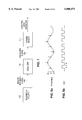
- FIG. 12 shows the temporal relationship of the various timing signals.
- VIN is the sine wave preamble used during timing acquisition mode.
- RST is the VCO reset signal which causes a zero-phase restart of the clock to be initiated.
- Zero-phase restart of the PLL is initiated at an expected "0" crossing of the sine wave preamble by the falling edge of the RST signal.
- CK is the clock signal for the PLL.
- Control signal S2 which transitions low at the locations of the sine wave peaks, is used to cause the ADC circuits for the PLL to ignore every other sample. In particular, the PLL only uses samples at or near a "0" crossing.
- Control signal DIR provides slope sign information at the point the preamble is sampled.
- Control signal DIR is delayed in phase by an amount T/2 to account for the delay of the signal in the ADC slice due to latches 1110 and 1120. Therefore, the appropriate DIR signal is input into the Timing ACQ's when the input signal has had sufficient time to propagate through latch 1110 and latch 1120 into the Timing ACQ.
- V out in FIG. 11a-11c passes into encoder 1310 from the ADC bit slices 1305 as shown in FIG. 13.
- Encoder 1310 implements the one-to-one mapping shown in FIG. 10a to generate x and e from the thermometer code level representation.
- An embodiment for encoding x and e from the representation is shown in FIGS. 10b-10g.
- the specific implementation is dictated by design choices and depends in part on how many inputs an OR gate may have for a specific design choice.
- the sign function (see Eq. (7)) is implemented in a standard manner in the sign function implementation block 1315. Reduction of x to sign(x) allows the implementation of simplified multiplier 1330 and multiplier 1335.
- the sign(x) signal is provided to multiplier 1335 prior to delay 1320 and provides the present sample value, sign(x n ), to multiplier 1335.
- the signal e is provided to multiplier 1335 through delay 1325. Delay 1325 delays signal e for one clock cycle, thereby providing the previous e sample value, e n-1 , to multiplier 1335 at time step n.
- Multiplier 1335 performs the operation e n-1 *sign x n !.
- the e signal is provided to multiplier 1330 without going through delay 1325, providing the present e sample value, e n , to multiplier 1330.
- the signal sign(x) passes through delay 1320.
- Delay 1320 delays signal sign(x) for one clock cycle, thereby feeding previous signal sign(x n-1 ) into multiplier 1330 at time step n.
- Multiplier 1330 performs the operation e n * sign x n-1 !.
- the signal from multiplier 1330 is inverted before being added in adder 1340 to the signal from multiplier 1335.
- the adder 1340 performs the calculation of Eq. (6) for the phase error.
- the digital phase error calculated in adder 1340 is converted to an analog signal in DAC 660 which in one embodiment may be a charge pump.
- An I up or I down current of appropriate magnitude is sent from DAC 660 to PLL loop filter 675 (see FIG. 6) to generate a control voltage for VCO 635.
- VCO 635 either retards or advances the timing phase in response to the applied control voltage.
- y n is the sampled value
- x n is the ideal sample value that is closest to y n
- e n is the decision error and the sign function is defined as in Eq. (7).
- the circuit architecture embeds the implementation of the gain error calculations in the ADC to simplify the overall circuit implementation.
- the ADC's used in PRML channels are usually 6 bits and 2's complement in output format. However, this is merely one embodiment and an ADC may be used consisting of n bits of output where n is an appropriate integer.
- the equation for gain error, Eq. (8) suggests a new encoding method for the ADC output.
- the ADC output can be encoded in the (x,e) format.
- a one-to-one mapping exists between the CMP output values and the (x,e) representation. The mapping of the CMP output values to the (x,e) is performed by standard combinational logic and the resulting representation is shown in FIG.
- An intermediate stage between the analog continuous-time acquisition mode and the digital discrete-time tracking mode consists of a high bandwidth digital discrete-time loop operating in acquisition mode.
- the intermediate stage compensates for potential mismatches between the voltage reference of the analog acquisition loop and the voltage reference of the ADC during the digital tracking loop.
- the acquisition mode is divided into two substages, analog continuous-time mode and digital discrete-time mode.
- the key difference between the acquisition digital mode and the tracking digital mode is that the acquisition mode has a higher closed loop bandwidth.
- the higher bandwidth of the digital discrete-time loop during acquisition allows mismatches between the voltage references of the analog acquisition loop and the voltage reference for the ADC to be compensated before data handling occurs.
- the voltage reference for the analog acquisition loop is made programmable so that its difference from the ADC voltage reference can be minimized by setting its value appropriately.
- the voltage reference will vary from chip to chip because it depends on the characteristics of the individual chip. Further the operating environment (i.e. temperature) of the chip will affect the voltage levels so the programmable voltage reference is not sufficient to overcome the potential mismatch in the AGC circuit.
- FIG. 14 shows one embodiment of the analog acquisition AGC loop.
- the signal being processed is the sine wave preamble in one embodiment.
- Sine wave preamble signal on lead 1406 enters variable gain amplifier (VGA) 605 where the gain of signal on lead 1406 is adjusted.
- VGA variable gain amplifier
- Gain adjusted signal on lead 1408 is filtered and equalized in ER filter block 610 (see also FIG. 6).
- Equalized signal on lead 1416 (FIG. 14) feeds into full wave rectifier 1420. A rectified signal is needed for adder 1425. Rectified signal on lead 1422 is inverted and summed with AGC reference signal on lead 1499 in adder 1425.
- Reference AGC signal on lead 1499 is generated in 7-bit digital-to-analog converter (DAC) 1440 which contains a programmable register for setting the desired level of the AGC reference signal on lead 1499.
- Output signal on lead 1428 is the difference between rectified acquisition signal on lead 1422 and AGC reference signal on lead 1499. Hence, difference signal on lead 1428 represents gain error.
- Difference signal on lead 1428 is sent into low pass filter (LPF) 1430 to remove the high frequency noise residing on difference signal on lead 1428.
- Voltage to current converter (Gm) 1435 converts filtered difference signal on lead 1432 from a voltage into a current with gain Gm. The filter serves to integrate the difference signal to smooth out rapid fluctuations.
- Gain loop filter 690 provides a control voltage to VGA 605 to increase or decrease the gain by an appropriate amount.
- the analog gain acquisition mode functions to provide approximately the correct gain during gain acquisition mode.
- the digital gain acquisition mode serves to fine tune the gain applied to the acquisition signal.
- One embodiment of the digital acquisition mode gain detector of is shown in FIG. 15. Only comparators CMP32-CMP39 and CMPOO-CMP07 are used for the digital gain acquisition mode. Gain information is processed every 2T during acquisition mode where T is the sample time.
- CMP32-CMP39 are the comparators corresponding to thresholds 1+5/8 to 2+3/8, respectively while CMPOO-CMP07 are the comparators corresponding to thresholds -2-3/8 to -1-4/8, respectively.
- Comparators CMP08-CMP31 are not used during the digital gain acquisition mode. The use of only 16 comparators during digital gain acquisition mode allows for less complex circuitry and a faster calculation of the gain error.
- Encoder 1510 converts the comparator outputs into x and e representation to allow calculation of the gain error according to Eq. (8).
- the conversion of the thermometer code levels in encoder 1510 to (x,e) format in one embodiment uses a combination of OR gates as shown in FIGS. 10b-10g.
- x and e are output from encoder 1510 with signal e going directly to multiplier 1530.
- the sign function (see Eq.(7)) is implemented in a simplified manner in sign function implementation block 1520 since output signal on lead 1525 of sign function implementation block 1520 will be either high or low.
- Signal on lead 1525 representing sign (x n ) enters simplified multiplier 1530. A full multiplier is not needed since multiplier 1530 performs the operation e n * sign(x n ) with the output being either e or inverted e.
- Signal on lead 1535 representing a measure of the gain error ⁇ n , enters DAC 665 which in one embodiment may be a charge pump. An appropriate current is sent from DAC 665 to gain loop filter 690.
- Gain loop filter 690 produces a control voltage for VGA 605 which operates to either increase or decrease the gain applied to preamble input signal on lead 1406 during digital gain acquisition mode.
- FIG. 16 One embodiment of the tracking mode gain detector is shown in FIG. 16.
- the input data signal is digitized in ADC 1305 and encoded into (x,e) representation by encoder 1610.
- x is the ideal sample value (+2, +1, 0, -1, -2 in EPRML) closest to signal sample value y.
- Signal e enters multiplier 1630 directly from encoder 1610.
- the sign function (see Eq. (7)) is implemented in a standard manner in sign function implementation block 1620.
- Signal x enters sign function implementation block 1620 with resulting output signal on lead 1625 from sign function implementation block 1620 being either high, low or zero signal.
- Signal on lead 1625 enters multiplier 1630 with the reduction of x to sign(x) allowing implementation of simplified multiplier 1630.
- Simplified multiplier 1630 performs the operation e n *sign(x n ) which results in e, inverted e or zero signal.
- Output signal on lead 1635 from simplified multiplier 1630, representing a measure of the gain error enters DAC 670.
- the digital gain error calculated by multiplier 1630 is converted to an analog signal in DAC 670 which in one embodiment may be a charge pump.
- An appropriate current is sent from DAC 670 to gain loop filter 690 (see FIG. 6).
- Gain loop filter 690 produces a control voltage for VGA 605 which operates to either increase or decrease the gain applied to data input signal on lead 601 during digital gain tracking mode.
- EPR4 family systems EPR4, E 3 PR4, E 5 PR4, etc.
Abstract
Description
.o slashed..sub.n error =-y.sub.n *x.sub.n-1 +y.sub.n-1 *x.sub.n (1)
e.sub.n =y.sub.n -x.sub.n (3)
gain error.sub.n =e.sub.n *x.sub.n (4)
e.sub.n =y.sub.n -x.sub.n (5)
.o slashed..sub.n =-e*sign x.sub.n-1 !+e.sub.n-1 *sign x.sub.n !(6)
sign x!=+1 if x=+2, +1
sign x!=0 if x=0
sign x!=-1 if x=-2, -1 (7)
.o slashed..sub.n error =-(x.sub.n +e.sub.n)*x.sub.n-1 +(x.sub.n-1 +e.sub.n-1)*x.sub.n
=-e.sub.n *x.sub.n-1 +e.sub.n-1 *x.sub.n
γ.sub.n =e.sub.n *sign x.sub.n ! (8)
and e.sub.n =y.sub.n -x.sub.n
Claims (14)
sign x!=+1 if x=+2, +1
sign x!=0 if x=0
sign x!=-1 if x=-2, -1.
Priority Applications (1)
| Application Number | Priority Date | Filing Date | Title |
|---|---|---|---|
| US08/695,327 US5808573A (en) | 1996-08-01 | 1996-08-01 | Methods and structure for sampled-data timing recovery with reduced complexity and latency |
Applications Claiming Priority (1)
| Application Number | Priority Date | Filing Date | Title |
|---|---|---|---|
| US08/695,327 US5808573A (en) | 1996-08-01 | 1996-08-01 | Methods and structure for sampled-data timing recovery with reduced complexity and latency |
Publications (1)
| Publication Number | Publication Date |
|---|---|
| US5808573A true US5808573A (en) | 1998-09-15 |
Family
ID=24792560
Family Applications (1)
| Application Number | Title | Priority Date | Filing Date |
|---|---|---|---|
| US08/695,327 Expired - Lifetime US5808573A (en) | 1996-08-01 | 1996-08-01 | Methods and structure for sampled-data timing recovery with reduced complexity and latency |
Country Status (1)
| Country | Link |
|---|---|
| US (1) | US5808573A (en) |
Cited By (17)
| Publication number | Priority date | Publication date | Assignee | Title |
|---|---|---|---|---|
| US6005507A (en) * | 1997-02-17 | 1999-12-21 | Matsushita Electric Industrial Co., Ltd. | Data decoding apparatus |
| US6037886A (en) * | 1998-04-01 | 2000-03-14 | Texas Instruments Incorporated | Method and apparatus for extracting band and error values from digital samples of an analog signal |
| US6151365A (en) * | 1997-02-25 | 2000-11-21 | Sony Corporation | Information detecting apparatus and method |
| US6160508A (en) * | 1997-12-29 | 2000-12-12 | Telefonaktiebolaget Lm Ericsson | Method and device for analogue to digital conversion |
| EP1111606A1 (en) * | 1999-12-20 | 2001-06-27 | Fujitsu Limited | Clock adjustment apparatus for a data reproduction system and an apparatus having a data reproduction system including such a clock adjustment apparatus |
| WO2001047110A2 (en) * | 1999-12-22 | 2001-06-28 | Burr-Brown Japan, Ltd. | Method and apparatus for changing characteristics of device |
| US6346905B1 (en) * | 1998-11-27 | 2002-02-12 | Stmicroelectronics S.R.L. | Analog-to-digital flash converter for generating a thermometric digital code |
| US6397237B1 (en) * | 1998-06-26 | 2002-05-28 | Hitachi America Ltd. | Methods and apparatus for implementing and using processors with sign function capability |
| US6522489B1 (en) | 1999-12-21 | 2003-02-18 | Texas Instruments Incorporated | Efficient analog-to-digital converter for digital systems |
| US6542101B1 (en) * | 2000-07-14 | 2003-04-01 | Lucent Technologies Inc. | Method and apparatus for performing analog-to-digital conversion using previous signal sample(s) |
| US6567489B1 (en) * | 1999-02-08 | 2003-05-20 | Texas Instruments Incorporated | Method and circuitry for acquiring a signal in a read channel |
| US20040090356A1 (en) * | 2002-11-11 | 2004-05-13 | Masaru Sekiguchi | Digital / analog converter |
| US6793938B2 (en) | 1998-07-17 | 2004-09-21 | Skye Pharma, Inc. | Biodegradable compositions for the controlled release of encapsulated substances |
| US20080219380A1 (en) * | 2007-03-08 | 2008-09-11 | Texas Instruments Incorporated | Data Encoding in a Clocked Data Interface |
| US7816959B1 (en) * | 2009-02-23 | 2010-10-19 | Integrated Device Technology, Inc. | Clock circuit for reducing long term jitter |
| US9337874B1 (en) * | 2014-12-18 | 2016-05-10 | Intel IP Corporation | High-speed digital signal processing systems |
| US9444480B1 (en) * | 2016-02-25 | 2016-09-13 | The Boeing Company | Radiation-hardened interleaved analog-to-digital converter circuits and methods of calibrating the same |
Citations (46)
| Publication number | Priority date | Publication date | Assignee | Title |
|---|---|---|---|---|
| US4015238A (en) * | 1975-11-24 | 1977-03-29 | Harris Corporation | Metric updater for maximum likelihood decoder |
| US4571734A (en) * | 1983-08-05 | 1986-02-18 | International Business Machines Corporation | Method and apparatus for decoding the output signal of a partial-response class-IV communication or recording-device channel |
| US4609907A (en) * | 1984-10-31 | 1986-09-02 | International Business Machines Corporation | Dual channel partial response system |
| US4644564A (en) * | 1983-08-05 | 1987-02-17 | International Business Machines Corporation | Decoding the output signal of a partial-response class-IV communication or recording device channel |
| US4829575A (en) * | 1985-11-12 | 1989-05-09 | National Research Development Corporation | Apparatus and methods for analyzing transitions in finite state machines |
| US4860012A (en) * | 1986-02-14 | 1989-08-22 | Microchip Technology Incorporated | Integrated analog-to-digital converter |
| US4870416A (en) * | 1986-05-16 | 1989-09-26 | Plessey Overseas Limited | Analogue to digital converters |
| US4910515A (en) * | 1987-02-25 | 1990-03-20 | Yamaha Corporation | Digital signal processing circuit |
| US5027374A (en) * | 1990-03-26 | 1991-06-25 | Motorola, Inc. | Bit serial Viterbi decoder add/compare/select array |
| US5196849A (en) * | 1992-01-31 | 1993-03-23 | International Business Machines Corporation | Method and apparatus for implementing PRML codes with maximum ones |
| US5208594A (en) * | 1991-05-02 | 1993-05-04 | Ricoh Company, Ltd. | Signal processor that uses a delta-sigma modulation |
| US5220466A (en) * | 1991-05-21 | 1993-06-15 | International Business Machines Corporation | Method and apparatus for digital filter control in a partial-response maximum-likelihood disk drive system |
| US5220294A (en) * | 1990-05-21 | 1993-06-15 | Nec Corporation | Phase-locked loop circuit |
| US5233482A (en) * | 1991-07-31 | 1993-08-03 | International Business Machines Corporation | Thermal asperity compensation for PRML data detection |
| US5241309A (en) * | 1989-08-16 | 1993-08-31 | International Business Machines Corporation | Data coding for fast start-up of prml receivers |
| US5258933A (en) * | 1992-08-27 | 1993-11-02 | Quantum Corporation | Timing control for PRML class IV sampling data detection channel |
| US5276408A (en) * | 1990-10-22 | 1994-01-04 | Nec Corporation | PLL frequency synthesizer capable of changing an output frequency at a high speed |
| US5291499A (en) * | 1992-03-16 | 1994-03-01 | Cirrus Logic, Inc. | Method and apparatus for reduced-complexity viterbi-type sequence detectors |
| US5341387A (en) * | 1992-08-27 | 1994-08-23 | Quantum Corporation | Viterbi detector having adjustable detection thresholds for PRML class IV sampling data detection |
| US5359631A (en) * | 1992-09-30 | 1994-10-25 | Cirrus Logic, Inc. | Timing recovery circuit for synchronous waveform sampling |
| US5375145A (en) * | 1992-08-27 | 1994-12-20 | Quantum Corporation | Multi-mode gain control loop for PRML class IV sampling data detection channel |
| US5408503A (en) * | 1992-07-03 | 1995-04-18 | U.S. Philips Corporation | Adaptive viterbi detector |
| US5408502A (en) * | 1992-07-13 | 1995-04-18 | General Instrument Corporation | Apparatus and method for communicating digital data using trellis coded QAM with punctured convolutional codes |
| US5410556A (en) * | 1993-10-29 | 1995-04-25 | Ampex Corporation | Pipelined viterbi decoder |
| US5412669A (en) * | 1993-12-09 | 1995-05-02 | Cirrus Logic, Inc. | Add, compare and select circuit |
| US5414738A (en) * | 1993-11-09 | 1995-05-09 | Motorola, Inc. | Maximum likelihood paths comparison decoder |
| US5418795A (en) * | 1991-09-13 | 1995-05-23 | Sony Corporation | Viterbi decoder with path metric comparisons for increased decoding rate and with normalization timing calculation |
| US5422760A (en) * | 1992-08-27 | 1995-06-06 | Quantum Corp. | Disk drive method using zoned data recording and PRML sampling data detection with digital adaptive equalization |
| US5430768A (en) * | 1994-09-21 | 1995-07-04 | Seagate Technology, Inc. | Maximum likelihood detector for a disc drive PRML read channel |
| US5432804A (en) * | 1993-11-16 | 1995-07-11 | At&T Corp. | Digital processor and viterbi decoder having shared memory |
| US5432820A (en) * | 1990-11-19 | 1995-07-11 | Fujitsu Limited | Maximum-likelihood decoding method and device |
| US5436932A (en) * | 1993-01-05 | 1995-07-25 | Yamaha Corporation | For performing amplitude-phase demodulation and viterbi decoding |
| US5438460A (en) * | 1992-08-13 | 1995-08-01 | International Business Machines Corporation | Asynchronous gain adjustment for PRML disk drive systems |
| US5444721A (en) * | 1991-11-27 | 1995-08-22 | Nec Corporation | Maximum likelihood sequence estimation apparatus |
| US5446746A (en) * | 1992-08-31 | 1995-08-29 | Samsung Electronics Co., Ltd. | Path memory apparatus of a viterbi decoder |
| US5450445A (en) * | 1991-10-31 | 1995-09-12 | Nec Corporation | Method and arrangement of estimating data sequences transmitted using viterbi algorithm |
| US5453997A (en) * | 1993-03-05 | 1995-09-26 | Motorola, Inc. | Decoder selection |
| US5459679A (en) * | 1994-07-18 | 1995-10-17 | Quantum Corporation | Real-time DC offset control and associated method |
| US5461644A (en) * | 1992-07-03 | 1995-10-24 | U.S. Philips Corporation | Adaptive viterbi detector |
| US5469452A (en) * | 1991-09-27 | 1995-11-21 | Qualcomm Incorporated | Viterbi decoder bit efficient chainback memory method and decoder incorporating same |
| US5502735A (en) * | 1991-07-16 | 1996-03-26 | Nokia Mobile Phones (U.K.) Limited | Maximum likelihood sequence detector |
| US5504984A (en) * | 1993-12-13 | 1996-04-09 | Sumitomo Electric Industries, Ltd. | Methods of manufacturing Nb3 Al superconducting wire and coil |
| US5509020A (en) * | 1993-05-27 | 1996-04-16 | Sony Corporation | Viterbi decoding apparatus and methods |
| US5508993A (en) * | 1994-02-01 | 1996-04-16 | Pioneer Electronic Corporation | Digital signal reproducing apparatus using a Viterbi decoder |
| US5521945A (en) * | 1995-06-30 | 1996-05-28 | Quantum Corporation | Reduced complexity EPR4 post-processor for sampled data detection |
| US5539780A (en) * | 1993-10-28 | 1996-07-23 | Motorola, Inc. | Computationally efficient data decoder and method used therein |
-
1996
- 1996-08-01 US US08/695,327 patent/US5808573A/en not_active Expired - Lifetime
Patent Citations (46)
| Publication number | Priority date | Publication date | Assignee | Title |
|---|---|---|---|---|
| US4015238A (en) * | 1975-11-24 | 1977-03-29 | Harris Corporation | Metric updater for maximum likelihood decoder |
| US4571734A (en) * | 1983-08-05 | 1986-02-18 | International Business Machines Corporation | Method and apparatus for decoding the output signal of a partial-response class-IV communication or recording-device channel |
| US4644564A (en) * | 1983-08-05 | 1987-02-17 | International Business Machines Corporation | Decoding the output signal of a partial-response class-IV communication or recording device channel |
| US4609907A (en) * | 1984-10-31 | 1986-09-02 | International Business Machines Corporation | Dual channel partial response system |
| US4829575A (en) * | 1985-11-12 | 1989-05-09 | National Research Development Corporation | Apparatus and methods for analyzing transitions in finite state machines |
| US4860012A (en) * | 1986-02-14 | 1989-08-22 | Microchip Technology Incorporated | Integrated analog-to-digital converter |
| US4870416A (en) * | 1986-05-16 | 1989-09-26 | Plessey Overseas Limited | Analogue to digital converters |
| US4910515A (en) * | 1987-02-25 | 1990-03-20 | Yamaha Corporation | Digital signal processing circuit |
| US5241309A (en) * | 1989-08-16 | 1993-08-31 | International Business Machines Corporation | Data coding for fast start-up of prml receivers |
| US5027374A (en) * | 1990-03-26 | 1991-06-25 | Motorola, Inc. | Bit serial Viterbi decoder add/compare/select array |
| US5220294A (en) * | 1990-05-21 | 1993-06-15 | Nec Corporation | Phase-locked loop circuit |
| US5276408A (en) * | 1990-10-22 | 1994-01-04 | Nec Corporation | PLL frequency synthesizer capable of changing an output frequency at a high speed |
| US5432820A (en) * | 1990-11-19 | 1995-07-11 | Fujitsu Limited | Maximum-likelihood decoding method and device |
| US5208594A (en) * | 1991-05-02 | 1993-05-04 | Ricoh Company, Ltd. | Signal processor that uses a delta-sigma modulation |
| US5220466A (en) * | 1991-05-21 | 1993-06-15 | International Business Machines Corporation | Method and apparatus for digital filter control in a partial-response maximum-likelihood disk drive system |
| US5502735A (en) * | 1991-07-16 | 1996-03-26 | Nokia Mobile Phones (U.K.) Limited | Maximum likelihood sequence detector |
| US5233482A (en) * | 1991-07-31 | 1993-08-03 | International Business Machines Corporation | Thermal asperity compensation for PRML data detection |
| US5418795A (en) * | 1991-09-13 | 1995-05-23 | Sony Corporation | Viterbi decoder with path metric comparisons for increased decoding rate and with normalization timing calculation |
| US5469452A (en) * | 1991-09-27 | 1995-11-21 | Qualcomm Incorporated | Viterbi decoder bit efficient chainback memory method and decoder incorporating same |
| US5450445A (en) * | 1991-10-31 | 1995-09-12 | Nec Corporation | Method and arrangement of estimating data sequences transmitted using viterbi algorithm |
| US5444721A (en) * | 1991-11-27 | 1995-08-22 | Nec Corporation | Maximum likelihood sequence estimation apparatus |
| US5196849A (en) * | 1992-01-31 | 1993-03-23 | International Business Machines Corporation | Method and apparatus for implementing PRML codes with maximum ones |
| US5291499A (en) * | 1992-03-16 | 1994-03-01 | Cirrus Logic, Inc. | Method and apparatus for reduced-complexity viterbi-type sequence detectors |
| US5461644A (en) * | 1992-07-03 | 1995-10-24 | U.S. Philips Corporation | Adaptive viterbi detector |
| US5408503A (en) * | 1992-07-03 | 1995-04-18 | U.S. Philips Corporation | Adaptive viterbi detector |
| US5408502A (en) * | 1992-07-13 | 1995-04-18 | General Instrument Corporation | Apparatus and method for communicating digital data using trellis coded QAM with punctured convolutional codes |
| US5438460A (en) * | 1992-08-13 | 1995-08-01 | International Business Machines Corporation | Asynchronous gain adjustment for PRML disk drive systems |
| US5341387A (en) * | 1992-08-27 | 1994-08-23 | Quantum Corporation | Viterbi detector having adjustable detection thresholds for PRML class IV sampling data detection |
| US5258933A (en) * | 1992-08-27 | 1993-11-02 | Quantum Corporation | Timing control for PRML class IV sampling data detection channel |
| US5422760A (en) * | 1992-08-27 | 1995-06-06 | Quantum Corp. | Disk drive method using zoned data recording and PRML sampling data detection with digital adaptive equalization |
| US5375145A (en) * | 1992-08-27 | 1994-12-20 | Quantum Corporation | Multi-mode gain control loop for PRML class IV sampling data detection channel |
| US5446746A (en) * | 1992-08-31 | 1995-08-29 | Samsung Electronics Co., Ltd. | Path memory apparatus of a viterbi decoder |
| US5359631A (en) * | 1992-09-30 | 1994-10-25 | Cirrus Logic, Inc. | Timing recovery circuit for synchronous waveform sampling |
| US5436932A (en) * | 1993-01-05 | 1995-07-25 | Yamaha Corporation | For performing amplitude-phase demodulation and viterbi decoding |
| US5453997A (en) * | 1993-03-05 | 1995-09-26 | Motorola, Inc. | Decoder selection |
| US5509020A (en) * | 1993-05-27 | 1996-04-16 | Sony Corporation | Viterbi decoding apparatus and methods |
| US5539780A (en) * | 1993-10-28 | 1996-07-23 | Motorola, Inc. | Computationally efficient data decoder and method used therein |
| US5410556A (en) * | 1993-10-29 | 1995-04-25 | Ampex Corporation | Pipelined viterbi decoder |
| US5414738A (en) * | 1993-11-09 | 1995-05-09 | Motorola, Inc. | Maximum likelihood paths comparison decoder |
| US5432804A (en) * | 1993-11-16 | 1995-07-11 | At&T Corp. | Digital processor and viterbi decoder having shared memory |
| US5412669A (en) * | 1993-12-09 | 1995-05-02 | Cirrus Logic, Inc. | Add, compare and select circuit |
| US5504984A (en) * | 1993-12-13 | 1996-04-09 | Sumitomo Electric Industries, Ltd. | Methods of manufacturing Nb3 Al superconducting wire and coil |
| US5508993A (en) * | 1994-02-01 | 1996-04-16 | Pioneer Electronic Corporation | Digital signal reproducing apparatus using a Viterbi decoder |
| US5459679A (en) * | 1994-07-18 | 1995-10-17 | Quantum Corporation | Real-time DC offset control and associated method |
| US5430768A (en) * | 1994-09-21 | 1995-07-04 | Seagate Technology, Inc. | Maximum likelihood detector for a disc drive PRML read channel |
| US5521945A (en) * | 1995-06-30 | 1996-05-28 | Quantum Corporation | Reduced complexity EPR4 post-processor for sampled data detection |
Non-Patent Citations (58)
| Title |
|---|
| "A 16MB/s PRML Read/Write Data Channel", Raymond A, Richetta et al., ISSCC95, Session 5, Disk and Arithmetic Signal Processor, Paper WP 5.1, pp. 78-79 and 58-59 (1995). |
| "A 3.0 V 40 Mb/s hard Disk Drive Read Channel IC", Geert A. De Veirman et al., IEEE Journal of Solid-State of Circuits, vol. 30, No. 7, pp. 788-799 (Jul. 1995). |
| "A Class of Partial Response Systems for Increasing Storage Density in Magnetic Recording", H.K. Thapar et al., IEEE Transactions on Magnetics, vol., Mzag. 23, No. 5, pp. 3666-3668 (Sep. 1987). |
| "A Digital Chip with Adaptive Equalizer for PRML Detection in Hard-Disk Drives", William L. Abbott et al., ISSC94, Session 17, Disk-Drive Electronics, Paper FA 17.5 pp. 284-285 (1984). |
| "A High Speed, Low Power PRML Read Channel Device", Jeff Sonntag et al., IEEE Transactions on Magnetics, vol. 31, No. 2, pp. 1186-1195 (Mar. 1995). |
| "A PRML System for Digital Magnetic Recording", Roy D. Cideciyan et al., IEEE Journal on Selected Areas in Communications, vol. 10, No. 1, pp. 38-56 (Jan. 1992). |
| "A Survey of Digital Phase-Locked Loops", William C. Lindsey et al., Proceedings of the IEEE, vol. 69, No. 4, pp. 410-431 (Apr. 1981). |
| "An Experimental 180 Mb/sec PRML Channel for Magnetic Recording", John Hong et al., IEEE Transactions on Magnetics, vol. 27, No. 6, pp. 4532-4537 (Nov. 1991). |
| "Analog Front-End Architectures for High-Speed PRML Magnetic Read Channels", Patrick K.D. Pai et al., IEEE Transactions on Magnetics, vol. 31, No. 2, (Mar. 1995). |
| "Design and Performance of a VLSI 120 Mb/s Trellis-Coded Partial Response Channel", J. W. Rae et al., IEEE Transactions on Magnetics, vol. 31, No. 2, pp. 1208-1214, (Mar. 1995). |
| "Error Rate Performance of Experimental Gigabit Per Square Inch Recording Components", Thomas D. Howell et al., IEEE Transactions on Magnetics, vol. 26, No. 5, pp. 2298-2302 (Sep. 1990). |
| "Exact Bounds for Viterbi Detector Path Metric Differences", Paul H. Seigel et al., pp. 1093-1096, (1991). |
| "Fast Timing Recovery for Partial-Response Signalling Systems", F. Dolivo, W. Schott and G. Ungerbock, IBM Research Division, Zurich Research Laboratory, pp. 0573-0577 (1989) IEEE. |
| "Fully Integrated Analog Filters Using Bipolar-JFET Technology", Khen-Sang Tan and Paul R. Gray, IEEE Journal of Solid-State Circuits, vol. SC-13, No. 6, December 1978 (1978). |
| "HD153061TF 130-Mbps PRNL Data Channel Processor", Hitachi Advance Information, pp. 1-3, 29-34, (Jul. 1995). |
| "Implementation of a Digital Read/Write channel with EEPR4 Detection", Dave Welland et al., IEEE Transactions on Magnetics, vol. 31, No. 2 (Mar. 1995). |
| "Implementation of PRML in a Rigid Disk/Drive", J.D. Coker et al., IEEE Transactions on Magnetics, vol. 27, No. 6, pp. 4538-4543, (Nov. 1993). |
| "Improving Performance of PRML/EPRML Through Noise Prediction", E. Eleftheriou and W. Hirt, IBM Research Division, (1996). |
| "Improving Performance of PRML/EPRML through Noise Prediction", Evangelos Eleftheriou et al., Presented at INTERMAG96 International Magnetics Conference, pp. 1-3 (1996). |
| "Integrating a Partial Response Maximum Likelihood Data Channel into the IBM 0681 Disk Drive", J.C. Coker et al., Presented at the Twenty-Fourth Asilomar Conference on Signals, Systems & Computers, pp. 674-677, (1990). |
| "Parallelism in Analog and Digital PRML Magnetic Disk Read Channel Equalizers", Gregory T. Uehara and Paul R. Gray, IEEE Transactions on Magnetics, vol. 31, No. 2, pp. 1174-1179 (Mar. 1995). |
| "PERD: Partial Error Response Detection", Takushi Nishiya et al., IEEE Transactions on Magnetics, vol. 31, No. 6, pp. 3042-3044 (Nov. 1995). |
| "PRML: A Practical Approach", Alexander Taratorin, Guzik Technical Enterprises, pp. 1-93 (1995). |
| "Realization of a 1-V Active Filter Using a Linearization Technique Employing Plurality of Emitter-Coupled Paris", Hiroshi Tanimoto et al., IEEE Solid-State Circuits, vol. SC-26, No. 7 pp. 937-945 (Jul. 1991). |
| "Reduced Complexity Viterbi Detector Architectures for Partial Response Signalling", Gerhard Fettweis et al., IBM Research Division, pp. 1-2,4,6,8,10,12,14,16,18,20,22,24,26,28,30 (1995). |
| "Reduced Complexity Viterbi Detector Architectures for Partial Response Signalling", Gerhard Fettweis et al., Paper presented at Globecom Conference '95, pp. 559-563 (1995). |
| "The Viterbi Algorithm", G. David Forney, Jr., Proceedings of the IEEE, vol. 61, No. 3, pp. 268-278 (1976). |
| "Timing Recovery in Digital Synchronous Data receivers", Kurt H. Mueller and Markus Muller, IEEE Transactions on Communications, vol. COM-24, No. 5, pp. 516-531 (May 1976). |
| "Turbo-PRML: A Compromise EPRML Detector", Roger Wood, IEEE Transactions on Magnetics, vol. 29. No. 6, pp. 4018-4020 (Nov. 1993). |
| A 16MB/s PRML Read/Write Data Channel , Raymond A, Richetta et al., ISSCC95, Session 5, Disk and Arithmetic Signal Processor, Paper WP 5.1, pp. 78 79 and 58 59 (1995). * |
| A 3.0 V 40 Mb/s hard Disk Drive Read Channel IC , Geert A. De Veirman et al., IEEE Journal of Solid State of Circuits, vol. 30, No. 7, pp. 788 799 (Jul. 1995). * |
| A Class of Partial Response Systems for Increasing Storage Density in Magnetic Recording , H.K. Thapar et al., IEEE Transactions on Magnetics, vol., Mzag. 23, No. 5, pp. 3666 3668 (Sep. 1987). * |
| A Digital Chip with Adaptive Equalizer for PRML Detection in Hard Disk Drives , William L. Abbott et al., ISSC94, Session 17, Disk Drive Electronics, Paper FA 17.5 pp. 284 285 (1984). * |
| A High Speed, Low Power PRML Read Channel Device , Jeff Sonntag et al., IEEE Transactions on Magnetics, vol. 31, No. 2, pp. 1186 1195 (Mar. 1995). * |
| A PRML System for Digital Magnetic Recording , Roy D. Cideciyan et al., IEEE Journal on Selected Areas in Communications, vol. 10, No. 1, pp. 38 56 (Jan. 1992). * |
| A Survey of Digital Phase Locked Loops , William C. Lindsey et al., Proceedings of the IEEE, vol. 69, No. 4, pp. 410 431 (Apr. 1981). * |
| An Experimental 180 Mb/sec PRML Channel for Magnetic Recording , John Hong et al., IEEE Transactions on Magnetics, vol. 27, No. 6, pp. 4532 4537 (Nov. 1991). * |
| Analog Front End Architectures for High Speed PRML Magnetic Read Channels , Patrick K.D. Pai et al., IEEE Transactions on Magnetics, vol. 31, No. 2, (Mar. 1995). * |
| Design and Performance of a VLSI 120 Mb/s Trellis Coded Partial Response Channel , J. W. Rae et al., IEEE Transactions on Magnetics, vol. 31, No. 2, pp. 1208 1214, (Mar. 1995). * |
| Error Rate Performance of Experimental Gigabit Per Square Inch Recording Components , Thomas D. Howell et al., IEEE Transactions on Magnetics, vol. 26, No. 5, pp. 2298 2302 (Sep. 1990). * |
| Exact Bounds for Viterbi Detector Path Metric Differences , Paul H. Seigel et al., pp. 1093 1096, (1991). * |
| Fast Timing Recovery for Partial Response Signalling Systems , F. Dolivo, W. Schott and G. Ungerbock, IBM Research Division, Zurich Research Laboratory, pp. 0573 0577 (1989) IEEE. * |
| Fully Integrated Analog Filters Using Bipolar JFET Technology , Khen Sang Tan and Paul R. Gray, IEEE Journal of Solid State Circuits, vol. SC 13, No. 6, December 1978 (1978). * |
| HD153061TF 130 Mbps PRNL Data Channel Processor , Hitachi Advance Information, pp. 1 3, 29 34, (Jul. 1995). * |
| Implementation of a Digital Read/Write channel with EEPR4 Detection , Dave Welland et al., IEEE Transactions on Magnetics, vol. 31, No. 2 (Mar. 1995). * |
| Implementation of PRML in a Rigid Disk/Drive , J.D. Coker et al., IEEE Transactions on Magnetics, vol. 27, No. 6, pp. 4538 4543, (Nov. 1993). * |
| Improving Performance of PRML/EPRML Through Noise Prediction , E. Eleftheriou and W. Hirt, IBM Research Division, (1996). * |
| Improving Performance of PRML/EPRML through Noise Prediction , Evangelos Eleftheriou et al., Presented at INTERMAG96 International Magnetics Conference, pp. 1 3 (1996). * |
| Integrating a Partial Response Maximum Likelihood Data Channel into the IBM 0681 Disk Drive , J.C. Coker et al., Presented at the Twenty Fourth Asilomar Conference on Signals, Systems & Computers, pp. 674 677, (1990). * |
| Parallelism in Analog and Digital PRML Magnetic Disk Read Channel Equalizers , Gregory T. Uehara and Paul R. Gray, IEEE Transactions on Magnetics, vol. 31, No. 2, pp. 1174 1179 (Mar. 1995). * |
| PERD: Partial Error Response Detection , Takushi Nishiya et al., IEEE Transactions on Magnetics, vol. 31, No. 6, pp. 3042 3044 (Nov. 1995). * |
| PRML: A Practical Approach , Alexander Taratorin, Guzik Technical Enterprises, pp. 1 93 (1995). * |
| Realization of a 1 V Active Filter Using a Linearization Technique Employing Plurality of Emitter Coupled Paris , Hiroshi Tanimoto et al., IEEE Solid State Circuits, vol. SC 26, No. 7 pp. 937 945 (Jul. 1991). * |
| Reduced Complexity Viterbi Detector Architectures for Partial Response Signalling , Gerhard Fettweis et al., IBM Research Division, pp. 1 2,4,6,8,10,12,14,16,18,20,22,24,26,28,30 (1995). * |
| Reduced Complexity Viterbi Detector Architectures for Partial Response Signalling , Gerhard Fettweis et al., Paper presented at Globecom Conference 95, pp. 559 563 (1995). * |
| The Viterbi Algorithm , G. David Forney, Jr., Proceedings of the IEEE, vol. 61, No. 3, pp. 268 278 (1976). * |
| Timing Recovery in Digital Synchronous Data receivers , Kurt H. Mueller and Markus M u ller, IEEE Transactions on Communications, vol. COM 24, No. 5, pp. 516 531 (May 1976). * |
| Turbo PRML: A Compromise EPRML Detector , Roger Wood, IEEE Transactions on Magnetics, vol. 29. No. 6, pp. 4018 4020 (Nov. 1993). * |
Cited By (22)
| Publication number | Priority date | Publication date | Assignee | Title |
|---|---|---|---|---|
| US6005507A (en) * | 1997-02-17 | 1999-12-21 | Matsushita Electric Industrial Co., Ltd. | Data decoding apparatus |
| US6151365A (en) * | 1997-02-25 | 2000-11-21 | Sony Corporation | Information detecting apparatus and method |
| US6160508A (en) * | 1997-12-29 | 2000-12-12 | Telefonaktiebolaget Lm Ericsson | Method and device for analogue to digital conversion |
| US6037886A (en) * | 1998-04-01 | 2000-03-14 | Texas Instruments Incorporated | Method and apparatus for extracting band and error values from digital samples of an analog signal |
| US6397237B1 (en) * | 1998-06-26 | 2002-05-28 | Hitachi America Ltd. | Methods and apparatus for implementing and using processors with sign function capability |
| US6793938B2 (en) | 1998-07-17 | 2004-09-21 | Skye Pharma, Inc. | Biodegradable compositions for the controlled release of encapsulated substances |
| US6346905B1 (en) * | 1998-11-27 | 2002-02-12 | Stmicroelectronics S.R.L. | Analog-to-digital flash converter for generating a thermometric digital code |
| US6567489B1 (en) * | 1999-02-08 | 2003-05-20 | Texas Instruments Incorporated | Method and circuitry for acquiring a signal in a read channel |
| EP1111606A1 (en) * | 1999-12-20 | 2001-06-27 | Fujitsu Limited | Clock adjustment apparatus for a data reproduction system and an apparatus having a data reproduction system including such a clock adjustment apparatus |
| US6977879B1 (en) | 1999-12-20 | 2005-12-20 | Fujitsu Limited | Apparatus for adjusting phase of clock signal based on phase error calculated from sampled values of readout signal |
| US6522489B1 (en) | 1999-12-21 | 2003-02-18 | Texas Instruments Incorporated | Efficient analog-to-digital converter for digital systems |
| WO2001047110A2 (en) * | 1999-12-22 | 2001-06-28 | Burr-Brown Japan, Ltd. | Method and apparatus for changing characteristics of device |
| US6724264B2 (en) | 1999-12-22 | 2004-04-20 | Texas Instruments Incorporated | Controller for a device with change in characteristics |
| WO2001047110A3 (en) * | 1999-12-22 | 2002-06-06 | Burr Brown Japan Ltd | Method and apparatus for changing characteristics of device |
| US6542101B1 (en) * | 2000-07-14 | 2003-04-01 | Lucent Technologies Inc. | Method and apparatus for performing analog-to-digital conversion using previous signal sample(s) |
| US20040090356A1 (en) * | 2002-11-11 | 2004-05-13 | Masaru Sekiguchi | Digital / analog converter |
| US6747587B2 (en) * | 2002-11-11 | 2004-06-08 | Oki Electric Industry Co., Ltd | Digital / analog converter |
| US20080219380A1 (en) * | 2007-03-08 | 2008-09-11 | Texas Instruments Incorporated | Data Encoding in a Clocked Data Interface |
| US7605737B2 (en) * | 2007-03-08 | 2009-10-20 | Texas Instruments Incorporated | Data encoding in a clocked data interface |
| US7816959B1 (en) * | 2009-02-23 | 2010-10-19 | Integrated Device Technology, Inc. | Clock circuit for reducing long term jitter |
| US9337874B1 (en) * | 2014-12-18 | 2016-05-10 | Intel IP Corporation | High-speed digital signal processing systems |
| US9444480B1 (en) * | 2016-02-25 | 2016-09-13 | The Boeing Company | Radiation-hardened interleaved analog-to-digital converter circuits and methods of calibrating the same |
Similar Documents
| Publication | Publication Date | Title |
|---|---|---|
| US5796358A (en) | Methods and structure for combined analog and digital automatic gain control in sampled-data receivers | |
| US5808573A (en) | Methods and structure for sampled-data timing recovery with reduced complexity and latency | |
| US5754352A (en) | Synchronous read channel employing an expected sample value generator for acquiring a preamble | |
| US6246723B1 (en) | Sampled amplitude read channel employing early-decisions from a trellis sequence detector for sampling value estimation | |
| US5521767A (en) | Optimized equalizer system for data recovery and timing extraction in partial response read channels | |
| US5786951A (en) | Sampled amplitude read channel employing a discrete time noise generator for calibration | |
| JP2000251417A (en) | Phase error predicting method and device related to phase detector | |
| WO1996010254A9 (en) | Improved timing recovery for synchronous partial response recording | |
| JP3923143B2 (en) | 16/17 ENDEC for decoding a 17-bit code word into a 16-bit data word and a method for decoding a 17-bit code word into a 16-bit data word | |
| US5465059A (en) | Method and apparatus for timing acquisition of partial response class IV signaling | |
| US5838738A (en) | Coding to improve timing recovery in a sampled amplitude read channel | |
| US6556633B2 (en) | Timing recovery for data sampling of a detector | |
| US5786950A (en) | PR4 sampled amplitude read channel employing an NRZI write modulator and a PR4/NRZI converter | |
| US6067198A (en) | Apparatus and method for processing a data signal from a magnetic-media reading head | |
| US5559840A (en) | Digital timing recovery method and apparatus for a coded data channel | |
| US6922384B2 (en) | Information reproducing apparatus | |
| US5991914A (en) | Clock recovery using maximum likelihood sequence estimation | |
| US5943368A (en) | Transmission, recording and reproduction of a digital information signal | |
| JP3428339B2 (en) | Phase synchronization control circuit | |
| US6118606A (en) | Apparatus for generating a signal whose phase is synchronized with an inputted digital signal | |
| Raghavan et al. | On feed-forward and feedback timing recovery for digital magnetic recording systems | |
| JP2000182335A (en) | Pll circuit and optical disk device provided therewith | |
| JP3498333B2 (en) | Timing signal reproduction circuit and digital video signal processing device in data transmission system | |
| US7010065B2 (en) | Method and apparatus for word synchronization with large coding distance and fault tolerance for PRML systems | |
| US6882604B2 (en) | Method and apparatus for utilizing modulation codes that produce maximized sample timing information |
Legal Events
| Date | Code | Title | Description |
|---|---|---|---|
| AS | Assignment |
Owner name: NEC ELECTRONICS INC., CALIFORNIA Free format text: ASSIGNMENT OF ASSIGNORS INTEREST;ASSIGNORS:SHIH, SHIH-MING;PAN, TZU-WANG;CHERN, JENN-GANG;REEL/FRAME:008262/0502 Effective date: 19961202 |
|
| STCF | Information on status: patent grant |
Free format text: PATENTED CASE |
|
| FPAY | Fee payment |
Year of fee payment: 4 |
|
| FPAY | Fee payment |
Year of fee payment: 8 |
|
| REMI | Maintenance fee reminder mailed | ||
| FPAY | Fee payment |
Year of fee payment: 12 |
|
| SULP | Surcharge for late payment |
Year of fee payment: 11 |
|
| AS | Assignment |
Owner name: NEC ELECTRONICS AMERICA, INC., CALIFORNIA Free format text: CHANGE OF NAME OF ASSIGNEE;ASSIGNOR:NEC ELECTRONICS, INC.;REEL/FRAME:026110/0316 Effective date: 20020924 |
|
| AS | Assignment |
Owner name: RENESAS ELECTRONICS AMERICA, INC., CALIFORNIA Free format text: MERGER;ASSIGNOR:NEC ELECTRONICS AMERICA, INC.;REEL/FRAME:026110/0643 Effective date: 20100401 |