US5727074A - Method and apparatus for digital filtering of audio signals - Google Patents
Method and apparatus for digital filtering of audio signals Download PDFInfo
- Publication number
- US5727074A US5727074A US08/621,534 US62153496A US5727074A US 5727074 A US5727074 A US 5727074A US 62153496 A US62153496 A US 62153496A US 5727074 A US5727074 A US 5727074A
- Authority
- US
- United States
- Prior art keywords
- filter
- signal
- digital
- frequency domain
- frequencies
- Prior art date
- Legal status (The legal status is an assumption and is not a legal conclusion. Google has not performed a legal analysis and makes no representation as to the accuracy of the status listed.)
- Expired - Lifetime
Links
Images


Classifications
-
- H—ELECTRICITY
- H03—ELECTRONIC CIRCUITRY
- H03G—CONTROL OF AMPLIFICATION
- H03G5/00—Tone control or bandwidth control in amplifiers
- H03G5/005—Tone control or bandwidth control in amplifiers of digital signals
-
- H—ELECTRICITY
- H04—ELECTRIC COMMUNICATION TECHNIQUE
- H04R—LOUDSPEAKERS, MICROPHONES, GRAMOPHONE PICK-UPS OR LIKE ACOUSTIC ELECTROMECHANICAL TRANSDUCERS; DEAF-AID SETS; PUBLIC ADDRESS SYSTEMS
- H04R3/00—Circuits for transducers, loudspeakers or microphones
- H04R3/04—Circuits for transducers, loudspeakers or microphones for correcting frequency response
-
- H—ELECTRICITY
- H04—ELECTRIC COMMUNICATION TECHNIQUE
- H04S—STEREOPHONIC SYSTEMS
- H04S7/00—Indicating arrangements; Control arrangements, e.g. balance control
- H04S7/30—Control circuits for electronic adaptation of the sound field
- H04S7/307—Frequency adjustment, e.g. tone control
Definitions
- This invention relates to an audio reproduction apparatus, called a digital time domain equalizer, which allows the reproduction of audio signals to be controlled in such a way as to correct for imperfections in speakers, listening spaces and other elements of an audio reproduction system, and allows additional desired spectral characteristics, to be inserted into the audio signal.
- a transfer function of an audio reproduction system generally should be uniformly flat in amplitude as a function of its frequency spectrum. Also, in general, the system should have no severe phase distortions over its frequency spectrum. Such characteristics are important in recording studios where a flat spectrum makes it easier for the artist or producer to hear all frequencies and timing elements of the sound. There are exceptions to these generalizations. First, it is important that a system transfer function have a low cut filter with a corner frequency, say at 40 Hz. This is required because speakers are not physically capable of generating frequencies below a certain (speaker dependent) frequency. Second, some systems are specifically designed to have a transfer function "colored" by slightly boosting or attenuating certain frequencies. Third, production studios often choose to hear their "mixes" on systems that mimic the sound inside of an automobile, or via a radio, or sound system, or television in a room. Such systems are significantly non-flat in their frequency response.
- Deviations from a desired amplitude spectrum are a major problem in an audio reproduction system.
- the biggest culprits are the speakers and listening spaces.
- the amplitude-frequency spectrum of a speaker is generally not flat, and the amplitude spectrum of a room or auditorium is also not flat. Deviations in the amplitude spectrum also change with location of the listener in a listening space. This is because the radiation pattern of a speaker causes amplitudes as a function of frequency to vary with angles (horizontal and vertical) from the centerline of the speaker.
- the effects of the listening space geometry cause frequencies to vary in intensity as a function of position. This causes narrow and broad variations in the frequency response that change as a function of the listener's location.
- a digital equalizer is a digital processor, typically a special purpose microprocessor which is programed to perform the operations of a digital filter for the purpose of compensating for errors in the transfer function of a system. Typically, such microprocessor is called a Digital Signal Processor or a DSP.
- a digital filter is one embodiment of a discrete- time filter.
- any linear network or system with input and output terminals can be characterized by describing its properties in terms of either the "frequency domain” or the "time domain".
- a ⁇ frequency domain ⁇ description of a system is one in which amplitude and phase of an output signal from the system are represented as a function of signal frequency. In the frequency domain, one does not deal explicitly with time functions but instead, for example, with Fourier or Laplace transforms and the like, which are functions of frequency.
- the "time domain” description is one in which the amplitude of the output signal of the system is represented purely as a function of time. Typically a time domain description is contained in the impulse response of the system to an input impulse which ideally is of infinitesimal duration and unit amplitude. It is recognized that the time domain and frequency domain systems are mathematically related, and typically one may be transformed into the other by known transformations. For example, in the frequency domain the transfer function of the network or system can be described as the Fourier transform of its impulse response.
- a digital filter!. . . operates in the time domain, and employs discrete-time filter means specially adaptable for equalizing the sound arriving at a listener's selected location.”
- the sound is sampled!. . . "in the time domain, a process which translates such samples into numerical values, and then the latter are convolved with a set of predetermined filter coefficients.
- a sampled and digitized signal of speech, music or any other time-varying quantity can be considered as a sequence of impulses of varying amplitude and polarity, the magnitude and polarity of any impulse corresponding to the magnitude and polarity of the original signal waveform at the exact time of sampling.
- a digital representation of the impulse response of a filter after the impulse response has been sampled and digitized, consists generally of a finite sequence of numbers, the numbers corresponding to amplitude during consecutive sampling periods, i.e. spaced equally apart in time. Each such number in the series bears a fixed proportional relation to the others. Any convenient numerical scale can be used to represent the filter impulse response, which is fully defined by this proportional relation.
- the absolute values of the numbers in the sequence are exactly proportional to the magnitude of the applied impulse, and it is common to assume in such descriptions that this magnitude has a numerical value of 1.0, with the impulse designated the unit impulse, S(n), although clearly one can arbitrarily scale the numbers of the sequence.
- Convolution of a digital filter impulse response and a sampled digitized signal will thus create a sequence of sums of scaled filter impulse response.
- the result of the convolution process is an output signal as described in the following exemplary way, simplified for purposes of exposition.
- the values of the filter impulse response need not correspond to the physical response of any existing analog filter or system, but can be simply any sequence of numbers designated a filter. It is therefore possible to create a digital filter which could be synthesized with analog filter components, such as a sparsely populated filter i.e. one in which a section of the filter impulse response is zero.
- the filter numbers are ordinarily referred to as ⁇ coefficients ⁇ .
- a conventional mathematical expression for the convolution process derives the final output signal values one at a time by summing the products of previous consecutive input signal values and the coefficients:
- x(n) is the input signal to the filter at discrete time n, m is the number of coefficients:
- c j are the filter coefficients, i.e., the numerical values of the coefficients m of the filter impulse response;
- j is an index from o to m
- y(n) is the output signal from the filter.
- equalizers Systems designed to correct for undesired deviations from a desired spectrum in audio reproduction systems are known as equalizers.
- the term equalizer refers to a system which compensates or corrects for undesired amplitude-frequency response of an audio reproduction system with respect to a given environment. More precisely, an equalizer is a device which alters the transfer function of one part of a system to compensate for errors in the transfer function of another part of that system; although the parts of the system may have non-uniform individual transfer functions, the overall performance of the system is thus improved.
- the first are multiband equalizers. (See U.S. Pat. No. 4,739,513, U.S. Pat. No. 5,384,856, U.S. Pat No. 5,195,141 and U.S. Pat. No. 5,210,806.) Because this invention does not relate to multiband equalizers, a discussion of their characteristics is not made here.
- equalizers are digital time domain equalizers (or simply "digital equalizers") which contain time domain filters or simply “digital filters” and are designed as a FIR (finite impulse response) or an IIR (infinite impulse response) filter for implementation in DSPs (digital signal processors).
- digital time domain equalizers or simply "digital equalizers" which contain time domain filters or simply “digital filters” and are designed as a FIR (finite impulse response) or an IIR (infinite impulse response) filter for implementation in DSPs (digital signal processors).
- Prior art methods and apparatus for FIR and IIR filter design for digital equalizers involve the playing (insertion or performance of) of a test signal into the audio system and recording the resulting sound signal on a calibration microphone. Such sound signal is then used as the input for the design of a digital filter.
- Filter design methods can be found by searching in the technical literature under the term "deconvolution”.
- prior art FIR and IIR filter design methods are known by such names as "Wiener filtering”, “least squares deconvolution”, “maximum likelihood estimation”, “maximum entropy spectral estimation”, “Prony Method”, “adaptive filter” and so on. Such methods often involve equations called the Yule-Walker equations or the "normal equations”.
- the amplitudes at frequencies from 500 to 1000 Hz are given as much attention in creating a flat amplitude vs. frequency characteristic, as the amplitudes at frequencies from 20,000 Hz to 20,500 Hz.
- a human ear works differently.
- the human ear assigns the same importance to sounds of all octaves in frequency. That is, the ear works logarithmically in frequency.
- the frequency range of 250 Hz to 500 Hz is a 250 Hz range. That range is subjectively as important as the frequency for 2,500 Hz to 5,000 Hz, a 2,500 Hz range. Consequently, the ear distinguishes with very high resolution in the frequency spectrum at very low frequencies, but with less resolution with increasing frequency.
- Multirate filtering refers to using two or more sample rates for filtering, those being the data sample rate (say, 44.1 kHz) and a lower sample rate, typically 1,000 Hz.
- a disadvantage of multirate sampling is that it requires a large number of computations to down-sample and up-sample the data, to provide crossover filters, and to filter two or more streams of data. Another failing is that the resulting frequency domain resolution, although improved in low frequencies, results in a stair-stepping of the frequency domain resolution, requiting overly-dense low frequency resolution just before a sudden change to a much less-dense high frequency resolution. To smooth this out requires even more multirate filters with more inefficient down-sampling and up-sampling, etc.
- a variation of multirate filtering is described by Genereux, "Adaptive Filters for Loudspeakers and Rooms", 93rd Convention of AES, 1992, October, which provides information on the only existing commercially available system, the AEC 1000.
- This system uses a 2,544 tap filter per channel at 44.1 KHz.
- the design of a filter is based on a multirate concepts and is described as: "High resolution is obtained at low frequencies by using a filter with a long impulse response. Then by selectively controlling the various segments of the filter's response, resolution can be made to decrease as frequency increases.”
- a primary object of this invention is therefore to provide an improved equalization system for an audio reproduction system.
- an important object of the invention is to provide an equalization system which has a digital filter which provides more resolution for low frequency signals than for high frequency signals.
- Another object of the present invention is to provide an efficient audio equalization system which avoids wasteful computations in prior art digital filter designs thereby providing the capability to incorporate a digital filter design into an inexpensive device used to accomplish digital audio equalization.
- Another object of this invention is to provide a new method for determining time domain filters implemented in the equalization system.
- step 2 Transforming the filter specified in step 2 into a new filter (always as an IIR filter) by inverse warping of the filter.
- a time domain filter (that is a digital filter) is produced that has high resolution at low frequencies and less resolution at higher frequencies. Because this resolution property is similar to the acuity of human heating, the ear perceives an equal qualitative improvement at all frequencies.
- the finite computational capacity of the system contributes a uniform perception of improvement to all frequencies with no computational waste. Therefore, such filter is efficient, allowing a single DSP chip to perform digital equalization on two or more channels of hi-fi audio data. In other words, fewer coefficients and delay taps are required to obtain improvements in the amplitude-frequency spectrum of the audio reproduction system.
- Warping of the frequency spectrum is accomplished by using the warping characteristics of a G(Z -1 ) transformation.
- the G(Z -1 ) transformation is used to map a plurality of amplitudes and phases at uniformly spaced frequencies into amplitudes and phases at new frequencies which are dense at low frequencies and less dense at high frequencies (or vice-a-versa).
- the final IIR filter has high resolution at low frequencies and less resolution at higher frequencies.
- step 2 The mathematical optimization performed in the filter design of step 2 (typically a least squared error formulation) honors all frequencies the same and has uniformly distributed resolution of amplitudes as a function of linear frequency. But in the "warped" frequency space of step 2, uniform ranges of frequency are equally important to the human ear. Hence a filter designed in step 2 is profoundly efficient, and generates no waste in computation. Also, because the forward warping transformation of step 1 and the inverse transformation of step 2 change only frequencies, not amplitudes or phases, then desirable properties of the filter design are preserved. Specifically, achieving a flat frequency response in step 2 results in a flat frequency response in the final filter created in step 3. Also, desirable phase attributes of the filters are preserved: minimum phase filters of step 2 become minimum phase in the final filter created in step 3. The final IIR filters have high resolution at low frequencies and less resolution at higher frequencies.
- the filter created by steps 1-3 are embodied in apparatus for modifying the audio response of an audio reproduction system, particularly in the form of an improved audio equalizer.
- An apparatus and method are provided for introduction of a test signal into the audio reproduction system.
- a microphone is used for detecting the acoustic output produced by the speaker of the audio reproduction system in response to the test signal at multiple locations in the listening space.
- a target transfer function is provided which has an arbitrary desired amplitude vs. frequency spectrum.
- the frequency response of the microphone is used in the system in a manner that removes the imperfections of the microphone from the equalizer.
- the coefficients and time slots of the digital filter produced are provided in a digital signal processor (DSP) circuit to physically realize the digital filter.
- DSP digital signal processor
- the processing efficiency of the system allows it to provide audio equalization with high resolution at low frequencies using a 1/20-th the number of coefficients of prior art systems with equivalent equalized response.
- This reduction in cost makes it economical to incorporate digital audio equalization in hi-fi systems, home theaters, automobiles, televisions, etc., thereby providing significantly improved sound quality and an overall cost reduction achieved by using less expensive speakers and fewer DSP circuits.
- FIG. 1 illustrates interconnections of a generalized audio reproduction apparatus during the calibration process
- FIG. 2 illustrates the interconnections of a generalized audio reproduction apparatus during normal operation
- FIG. 3 illustrates one embodiment of the invention, where a digital filter is produced and applied to an audio system or applied to apparatus for producing the filter on a ROM;
- FIG. 4 depicts a second embodiment of the invention where a digital filter that is stored on a ROM is used to program a DSP of an audio system for a car, a television, a home stereo unit, etc.;
- FIG. 5 illustrates a third embodiment where a personal computer is used to perform some of the operations depicted in FIG. 1;
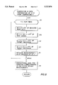
- FIG. 6 is a flowchart which illustrates a computer program used to design a filter for the DSPs of FIGS. 3, 4, and 5;
- FIG. 7 is a flowchart which illustrates a computer program used in the process of recording a test signal
- FIG. 8 is a flowchart which illustrates a computer program used in preparing measurement data for a filter production
- FIG. 9 is a flowchart which illustrates a computer program used in the process of creating a new filter from the measurement data.
- FIG. 10 is a graph which illustrates amplitude-frequency warping of an example Warp-Z transform.
- audio reproduction system is a broad term which refers to all elements of a signal path beginning with the source of the audio to the listener. Elements of the signal path include the reproduction equipment, the speakers, the listening environment (room, automobile, etc.) and the presence of the listener(s).
- apparatus by which an operator initiates the processing of audio data through the apparatus in such a way as the apparatus functions as a digital time domain equalizer.
- the operator may select among multiple filters.
- the filter coefficients of one or more filters are moved into the DSP and applied to the time-sampled sequence of points arriving from the digital input in such a way as to generate a time-sampled sequence of points passed to the digital output.
- an arrangement for outputting one or more filters via a serial port 26a to ROM reproduction equipment, 28.
- the purpose of this feature is apparent in the second embodiment of the invention illustrated in FIG. 4, where the DSP Section 10b is a stand-alone DSP (without connection to a CPU as in FIGS. 3, 5), and the filter coefficients are provided by a filter ROM 14b.
- the filter ROM 14b is produced by reproducing copies of a ROM created by ROM reproduction 28 (FIG. 3).
- FIG. 4 is appropriate where the invention is to be included in audio reproduction systems which are mass produced and have similar acoustic properties (e.g. automobiles, speaker systems, televisions, home theaters and computers for multi-media).
- the DSP Section 10c is connected to a personal computer 20c and to its CPU Section 21c via a serial link using Serial Ports 15c and 26c, respectively.
- This implementation is appropriate where the computer Section 20a of FIG. 3 is replaced by a personal computer 20c.
- This embodiment provides an inexpensive DSP Section 10c that can be purchased for home hi-fi use.
- H(z) when used to denote an IIR filter (or transfer function) has a z-domain representation given by ##EQU2##
- the notation FFT is used to denote the Fast Fourier Transform, as commonly found in the signal processing literature.
- the term FFT is used as a notational convenience, it being understood that the principles of the present invention can be carried out with similar means, such as using a standard Fourier Transform or a Cosine Transform.
- frequency domain data in the case of a digital or time sampled system, the "z" domain
- time domain data is computed by applying the inverse FFT to the frequency domain data.
- time domain data may be equivalently transformed in the form of a z transform, such as F(z), etc.
- the notation A ! is used to denoted an array of data values, such as a sequence of real time-sampled data or a sequence of complex FFT coefficients, depending on the context.
- FIGS. 1, 2, 3, 4, 5, 6, 7, 8 and 9 a digital time domain equalizer created by the methods of the present invention is shown in certain illustrative embodiments, for example in a single channel audio system, but the principles of the present invention are equally applicable to multichannel systems such as stereophonic systems. The principles of the present invention are equally applicable to more generalized equalizer systems, such as discussed in U.S. Pat. No. 4,683,590, incorporated herein by reference.
- FIG. 1 is a schematic illustration which depicts the arrangement of audio equipment which must be used during the process of acquiring measurements. It shows a mode of operation of the arrangements of FIGS. 3 and 5.
- Signals applied to the digital equalizer 10 are digital in form. Accordingly, continuous or analog signals are applied to an analog to digital (A/D) converter before they are input to the digital equalizer 60a. Signals output from digital equalizer are applied to a digital to analog (D/A) converter for application to an amplifier 61.
- the digital equalizer 10' of FIG. 2 is the object of invention as ultimately created using the arrangements of FIGS. 3 and 5.
- the digital filter so created is embodied in the DSP circuits and storage media for filter coefficient and taps of FIGS. 3, 4 and 5.
- An audio amplifier 61 is connected to the output of the digital equalizer 10 of FIG. 1.
- the connection between the digital equalizer 10 and the audio amplifier 61, the type of connectors, and the wiring arrangement can be any of several appropriate industry standards including EAS/EBU (digital), S/PDIF (digital), optical (digital), balanced line (analog) or unbalanced line (analog).
- the audio amplifier 61 is in turn attached to a speaker or speaker assembly 62 using a two wire speaker cable. During the measurements process, a test signal is emitted by the digital equalizer 10 and passes through the audio amplifier 61 to the speaker or speaker assembly 62. The resulting sound is detected by a microphone 63.
- the output of the microphone is attached to the input of the digital equalizer 10 where the type of connectors and wiring can be any of several appropriate industry standards including EAS/EBU (digital), S/PDIF (digital), optical (digital), balanced line (analog) or unbalanced line (analog).
- EAS/EBU digital
- S/PDIF digital
- optical digital
- balanced line analog
- unbalanced line analog
- FIG. 2 depicts the connection of audio equipment which is used during the equalization of audio signals.
- the digital equalizer 10' is a modified version of the digital equalizer 10 of FIG. 1 and is the object of the invention ultimately to be embodied in any of the DSP section of FIGS. 3, 4 and 5.
- the audio amplifier 61 and the speaker or speaker assembly 62 are connected together in the same way as described in relation to FIG. 1.
- the audio source 64 depicts a CD player, turntable, tuner, tape player, microphone, mixer output, television or any other source of audio data.
- the type of connectors and wiring between the Audio Source 64 and Digital Equalizer 60b can be any of several appropriate industry standards including EAS/EBU (digital), S/PDIF (digital), optical (digital), balanced line (analog) or unbalanced line (analog).
- FIG. 3 is a block diagram of an arrangement 100a including an equalizer section 10a for a producing a digital filter for embodiment in a DSP 12.
- the apparatus of FIG. 3 includes an equalizer section 10a and a CPU Section 20a.
- the equalizer section 10a includes Audio Digital In lead 11, an Audio Digital Out lead 13, Filter SRAM 14a, and a DSP 12.
- the DSP 12 is preferably a Motorola DSP 56002 chip.
- the CPU Section 20a includes a CPU 21a, a program ROM 22a, a Target Data ROM 23a, a Mic Data RAM/ROM 24a, a Test Signal ROM 25a, a serial port 26a, and a Scratch RAM 27a.
- CPU central processing unit
- DSP digital signal processor
- RAM random access memory
- SRAM static random access memory
- ROM read only memory
- Mic Mic
- the Digital Audio signal lead In 11 is so named because the flow of data from the Digital Audio In to the DSP 12 is digital serial data as conventionally applied to the SCI port of the DSP 12. Audio digital data is provided from connecting input sources from EAS/EBU (digital), S/PDIF (digital), optical (digital), balanced line (analog) or unbalanced line (analog) via a plurality conventional circuits.
- EAS/EBU digital
- S/PDIF digital
- optical digital
- balanced line analog
- unbalanced line analog
- the Audio Digital Signal Out lead 13 is so named because the flow of data from the DSP 12 lead 13 is digital serial data as conventionally used by, for example, a Motorola DSP56002 SCI port. Audio Digital Signal Out signal on lead 13 is applied to a plurality of circuits which provide a means of connecting outputs for EAS/EBU (digital), S/PDIF (digital), optical (digital), balanced line (analog) or unbalanced line (analog) outputs.
- EAS/EBU digital
- S/PDIF digital
- optical digital
- balanced line analog
- unbalanced line analog
- the circuits which provide Digital Audio signals In lead 11 and Audio Digital signals on Out lead 13 include conventional circuits for modulation/demodulation and flow control (as in the Motorola DSP56401), A/D and D/A conversion (as in the Crystal CS5389 and CS4328), common mode separation, anti-CMOS latch-up, balanced line drivers, unbalanced line drivers, impedance matching and transformer isolation.
- a DSP 12 is a device like the Motorola DSP56002 chip.
- the Filter SRAM 14a, the Filter ROM 14b of FIG. 4 are memory devices for storage of filter coefficients, and, depending on the DSP, a filter program.
- a CPU 21a of CPU Section 20a is a general purpose programmable micro-processor, such as a Motorola 68000.
- a Program ROM 22a stores a sequence of machine instructions executed by the CPU 21a. Flowcharts for such programs are illustrated below.
- a Target Data ROM 23a stores data which describes one or more target transfer functions, either as a time impulse response, or FFT coefficients.
- a Mic Data ROM/RAM 24a stores data which describes the microphone used to take the listening space measurements.
- the format can be either as a time impulse response, or FFT coefficients.
- a computer program in CPU 21a is provided where the operator can read the data values input from a mass storage device (not shown).
- a Test Signal ROM 25a stores a test signal used in the measurement process. Under control of CPU 21a, a test signal from Test Signal ROM 25a is applied to DSP 12 so that a test signal can be applied to amplifier 61 and speaker 62 as in FIG. 1.
- a Scratch RAM 27a is provided for temporary storage of intermediate values in the measurement and filter design production. Such scratch RAM 27a is used by CPU 21.
- the apparatus includes CPU 21a programmed to accomplish the process of collecting a measurement.
- a time-sampled sequence is generated, called the test signal, and which is routed through the DSP 12 to the digital output.
- Means are also provided for simultaneously routing data at the digital input (e.g., via AUDIO DIGITAL SIGNAL IN lead 11) (to which is connected a microphone) through the DSP 12, into the SCRATCH RAM 27a of the CPU 21a to be stored as a time-sampled sequence.
- Multiple occurrences of generation of the test signal are provided. Each such occurrence results in a new input time-sampled sequence to be summed with the previous time sampled sequences. All such multiple occurrences create a single time sampled sequence which is termed a "measurement".
- an operator When collecting multiple measurements, an operator places the microphone at different locations in the listening space and manually initiates the equipment in order to collect a new measurement.
- an input device 80 (such as a keyboard) is provided for the operator to start the generation of a filter.
- the operator specifies or inputs a description of the microphone that is used (in Mic Data RAM/ROM 24a) and specifies a target spectrum (in Target Data ROM 23a) that the apparatus is to use as an input to the filter design.
- the operator names the filter via input device 80.
- a means is provided such that the filter, consisting of coefficients to be applied to time delay taps on the input and output data, can be stored in SRAM 14a memory associated with DSP 12.
- FIG. 6 is a flowchart which depicts a computer program stored in Program ROM 22a to accomplish the process of collecting measurements, computing a filter and storing the filter to a desired destination.
- the flowchart of FIG. 6 provides an outline by which a computer programmer can readily prepare a computer program to control the operation of CPU 21a.
- An operator first connects the digital equalizer of 10a (FIG. 3) as indicated by FIG. 1 and places a microphone 63 in position for a measurement. The operator then initiates the program of FIG. 6.
- logic block 30 calls a subroutine which causes a measurement to be stored in Scratch RAM 27a.
- Control is next passed to the logic block 31, which causes the apparatus to query the operator (via a monitor not illustrated) as to whether another measurement should be recorded (provided sufficient Scratch RAM storage is available). The operator may then move the microphone to a different location and respond "Yes" via input device 80, and the sequence of recording a measurement is repeated. Otherwise, control is passed to the logic block 32.
- Logic block 32 calls a subroutine B which prepares data for the filter design.
- Logic block 33 calls subroutine C which causes a new filter to be generated and stored in Scratch RAM 27a of FIG. 3.
- Control is then passed to logic block 34 which causes the measurements to be erased from Scratch RAM 27a. Control is next passed to logic block 35 which causes the generated filter to be moved from Scratch RAM 14 to any of:
- FIG. 7 is a flowchart which enables a computer programmer to write code for causing a measurement to be stored in Scratch RAM 27a of FIG. 3.
- control passes to logic block 40 which initializes a block of memory, A !, to zero. Such memory is provided to store the summed data termed a measurement.
- Control then passes to logic block 41 which provides a loop of NTEST repetitions of playing a test signal. (NTEST had been a user input via an input device 80 e.g., a keyboard!.
- Control passes to logic block 42 which provides a loop of TEST -- LEN repetitions where the test signal is played and recorded, sample by sample, where TEST -- LEN is the number of samples in the test signal.
- the loops 41 and 42 cause blocks 43 and 44 to be repeated as indicated here.
- the test signal comprises TEST -- LEN different digital audio data samples.
- Logic block 43 causes the J-th test signal sample to be applied to DSP 12 which in turn passes it to the Audio Digital Signal output lead 13 for D/A conversion, amplification, broadcast via the speaker system and recording in CPU 21a.
- Logic block 44 provides a means of storing a time series sample which had just previously been received from microphone 63, via Audio Digital Signal Input 11 and through DSP 12 to CPU 21a. That sample is then summed into A J!, (the J-th sample of A !).
- the Scratch RAM 27a contains a single time sampled sequence stored in an array A !, which is termed a measurement.
- FIG. 8 is a flowchart which provides a computer programmer with an outline for production of code for data preparation required for filter generation.
- Many different kinds of filters may be generated. Consequently, there are a plurality of methods for data preparation as suggested by logic block 55.
- the sequence of operational steps shown in logic blocks 50, 51, 52, 53 and 54 illustrates a pre-processing of the measurement. Hence, the original measurement is, in effect, replaced by a new measurement.
- Such pre-processing is transparent to data preparation as required in block 55.
- Particular filter implementations may require different data preparation. For example, the Wiener-Levinson spiking deconvolution filter requires only that the average autocorrelation of the measurements be computed in the data preparation. With such knowledge as to the kind of filter to be generated, there may be more efficient ways to perform the steps of logic blocks 50, 51, 52, 53, 54 of FIG. 8.
- Logic block 50 of FIG. 8 causes a number NUM -- MEAS, repetitions of the enclosed code, of logic blocks 51-54, where NUM -- MEAS is the number of repetitions.
- Logic Block 51 causes the Fast Fourier Transform FFT of the I-th measurement to be moved into the array B ! where the work arrays, A !, B !, C !, D !, and E ! are physically located in Scratch RAM 27a of CPU Section 21a.
- Logic block 51a creates an array E ! by dividing the FFT of the test signal into the array B !.
- Logic block 52 creates an array C ! by dividing the FFT of the microphone response into the array E !. Such division causes the effects of imperfections in the frequency response of the microphone to be removed from the measurement data.
- Logic block 53 creates an array D ! by dividing the FFT of the target response stored in Target Data ROM 23a into the measurement, C !. This operation, in conjunction with the specific requirement that the filter which is generated flatten the amplitude-frequency response of the "apparent" system, causes the resulting filter to shape the processed audio output spectrum to be that of the target response.
- Logic block 54 causes the I-th measurement to be replaced with its pre-processed version, D !.
- Block 55 is the remainder of the data preparation as would be prescribed by whatever filter design technique is eventually implemented.
- One way for implementing logic block 54 is to compute the average autocorrelation of the measurements.
- FIG. 9 presents a flowchart which illustrates processing steps for filter generation as called for by logic block 33 of FIG. 6.
- logic block 71 is accomplished by any of a number of conventional FIR or IIR filter generating methods. Such methods are characterized in that variations in amplitude spectra occur (approximately) uniformly in frequency.
- the logic block 71 is preferred to be implemented by inverting and then smoothing (time windowing) the average power spectrum of the measurements and using the normal equations to produce the IIR filter ##EQU4## where F(z) is the solution to the normal equations.
- logic blocks 70 and 72 are such that the final filter which is produced is characterized by a frequency spectrum which has variations in amplitude with high resolution at low frequencies and less resolution at higher frequencies, a pattern very similar to the acuity of the human ear.
- the purpose of logic block 72 is to modify the conventionally designed filter produced in logic block 71 resulting in a final filter with the desired properties.
- the transform of logic block 70 is called the "Warp-Z” transform.
- the transform of logic block 72 is called the "inverse Warp-Z" transform.
- the inverse Warp-Z transform of logic block 72 transforms a conventionally designed FIR or IIR filter denoted by H(z) to a new IIR filter denoted H(Z).
- This mathematical transformation is defined as a mapping from the z-domain to the Z-domain given by
- the G(Z -1 ) transform is a symbolic algebraic substitution that transforms the filter H(z) to a new Z-domain filter denoted, H(Z).
- the G(Z -1 ) transform maps a plurality of amplitudes and phases at uniformly spaced frequencies of H(z) in the z domain to new frequencies of H(Z) in the Z domain which are dense at low frequencies and less dense at high frequencies. This "moving” or translating of amplitudes and phases from one set of frequencies to another is called “warping", and the G(Z -1 ) transform of logic block 72 is denoted as the "inverse Warp-Z" transform, because it un-does, or inverts, the effect of the forward transform in logic block 70.
- the inverse warp transform G(Z -1 ) has the following properties:
- the input, H(z) will be of the form of a FIR or an IIR filter.
- the output H(Z) will be an IIR filter.
- Values for L and ⁇ k of the G(Z -1 ) transform are chosen to satisfy the additional requirement that amplitudes and phases at uniformly spaced frequencies of H(z) map to new frequencies of H(Z) which are dense at low frequencies and less dense at high frequencies.
- the forward warping maps the z variables into Z variables where ⁇ and ⁇ are defined to be the frequency variables in the z-plane and the Z-plane, respectively, i.e.,
- the inverse Warp-Z transform acts to squeeze amplitude responses of given frequency of the H(z) transfer function into lower frequencies of the H(Z) transfer function.
- the filter H(Z) exhibits the property of high resolution at low frequencies and less resolution at higher frequencies.
- values for L and ⁇ k are chosen which give a form of G(Z -1 ) which is similar to the acuity of human hearing (high resolution at low frequencies).
- the principles of the present invention are equally applicable to other values of L and ⁇ k . That is, other values of L and ⁇ k can be chosen which provide high resolution at frequencies which are the most important for listening with a particular audio reproduction system.
- An example is where a speaker assembly has two speakers for low and high frequency reproduction which exhibit disturbances in the amplitude spectrum at frequencies near the crossover frequency of the speakers.
- the variables L and ⁇ k can be chosen which provide the highest perceived resolution at the problem crossover frequency.
- logic block 70 provides a means to stretch amplitudes and phases out of the low frequencies and into the high frequencies in an equal and opposite manner to that of the inverse Warp-Z transform, which acts to squeeze amplitudes and phases into lower frequencies.
- logic block 70 transforms the amplitude (and phase) at a frequency of 1447 Hz to 10,528 Hz.
- the conventional filter generator of logic block 71 produces a filter based upon data having the transformed frequencies.
- the logic block 72 performs the inverse Warp-Z transform to restore the original frequencies. For example, the filter amplitude at a frequency of 10,528 Hz is mapped back to a frequency of 1447 Hz.
- logic block 70 warps amplitudes and phases using the mapping depicted in FIG. 10, in order to effectively stretch amplitude (and phase) responses out of the low frequencies.
- Logic block 70 performs these operations on the FFT form of all time domain data that is used in the conventional filter design.
- the source code attached hereto at the end of this description under the heading "SOURCE CODE” presents a preferred embodiment of logic blocks 70, 71, and 72.
- the program language is c++. (Note, the source code uses equations where the sign of alpha is opposite that described above.)
Abstract
Description
z.sup.-1 =G(Z.sup.-1) (5)
z=e.sup.jθ and Z=e.sup.jω, then
e.sup.-jθ =|G(e.sup.-jω)|e.sup.jarg G(e.spsp.-jω.sup.)!(7)
|G(e.sup.-jω)|=1 (8)
θ=-arg G(e.sup.-jω)! (9)
Claims (10)
Priority Applications (1)
| Application Number | Priority Date | Filing Date | Title |
|---|---|---|---|
| US08/621,534 US5727074A (en) | 1996-03-25 | 1996-03-25 | Method and apparatus for digital filtering of audio signals |
Applications Claiming Priority (1)
| Application Number | Priority Date | Filing Date | Title |
|---|---|---|---|
| US08/621,534 US5727074A (en) | 1996-03-25 | 1996-03-25 | Method and apparatus for digital filtering of audio signals |
Publications (1)
| Publication Number | Publication Date |
|---|---|
| US5727074A true US5727074A (en) | 1998-03-10 |
Family
ID=24490556
Family Applications (1)
| Application Number | Title | Priority Date | Filing Date |
|---|---|---|---|
| US08/621,534 Expired - Lifetime US5727074A (en) | 1996-03-25 | 1996-03-25 | Method and apparatus for digital filtering of audio signals |
Country Status (1)
| Country | Link |
|---|---|
| US (1) | US5727074A (en) |
Cited By (54)
| Publication number | Priority date | Publication date | Assignee | Title |
|---|---|---|---|---|
| US6087736A (en) * | 1997-01-31 | 2000-07-11 | Honda Giken Kogyo Kabushiki Kaisha | Communication system for vehicle |
| US6195438B1 (en) * | 1995-01-09 | 2001-02-27 | Matsushita Electric Corporation Of America | Method and apparatus for leveling and equalizing the audio output of an audio or audio-visual system |
| US20030081804A1 (en) * | 2001-08-08 | 2003-05-01 | Gn Resound North America Corporation | Dynamic range compression using digital frequency warping |
| US20030128849A1 (en) * | 2002-01-07 | 2003-07-10 | Meyer Ronald L. | Acoustic anti-transient-masking transform system for compensating effects of undesired vibrations and a method for developing thereof |
| US20030195914A1 (en) * | 2002-04-12 | 2003-10-16 | Whikehart J. William | Sparse-coefficient functions for reducing computational requirements |
| US20030233229A1 (en) * | 2002-04-11 | 2003-12-18 | Wen-Long Tseng | Digital audio signal processing method with improved processing efficiency |
| US6765741B2 (en) | 2002-11-25 | 2004-07-20 | International Business Machines Corporation | Adjusting a read detection equalizer filter of a magnetic tape drive employing a recording format required control pattern |
| US6877116B1 (en) * | 1997-08-28 | 2005-04-05 | Seagate Technology Llc | Method and apparatus for determining bit error rate in a sampled data system without requiring read channel circuitry |
| US20050144534A1 (en) * | 2003-12-15 | 2005-06-30 | International Business Machines Corporation | Method, system, and program for real-time channel adaptation |
| US20050228646A1 (en) * | 2002-06-21 | 2005-10-13 | Carl Christensen | Broadcast router having a serial digital audio data stream decoder |
| US20060009970A1 (en) * | 2004-06-30 | 2006-01-12 | Harton Sara M | Method for detecting and attenuating inhalation noise in a communication system |
| US20060020451A1 (en) * | 2004-06-30 | 2006-01-26 | Kushner William M | Method and apparatus for equalizing a speech signal generated within a pressurized air delivery system |
| US6999826B1 (en) * | 1998-11-18 | 2006-02-14 | Zoran Corporation | Apparatus and method for improved PC audio quality |
| US20060153404A1 (en) * | 2005-01-07 | 2006-07-13 | Gardner William G | Parametric equalizer method and system |
| US7155388B2 (en) | 2004-06-30 | 2006-12-26 | Motorola, Inc. | Method and apparatus for characterizing inhalation noise and calculating parameters based on the characterization |
| US20070107585A1 (en) * | 2005-09-14 | 2007-05-17 | Daniel Leahy | Music production system |
| US7233268B1 (en) * | 2006-06-03 | 2007-06-19 | Rdw, Inc. | Multi-stage sample rate converter |
| US20070172079A1 (en) * | 2003-06-30 | 2007-07-26 | Markus Christoph | Handsfree communication system |
| US20080240467A1 (en) * | 2007-03-09 | 2008-10-02 | Srs Labs, Inc. | Frequency-warped audio equalizer |
| US20090017784A1 (en) * | 2006-02-21 | 2009-01-15 | Bonar Dickson | Method and Device for Low Delay Processing |
| US20100189282A1 (en) * | 2004-09-07 | 2010-07-29 | Audyssey Laboratories, Inc. | Phase equalization for multi-channel loudspeaker-room responses |
| US20140369521A1 (en) * | 2013-06-12 | 2014-12-18 | Anthony Bongiovi | System and method for narrow bandwidth digital signal processing |
| US20150117651A1 (en) * | 2013-10-31 | 2015-04-30 | Samsung Electronics Co., Ltd. | Audio output apparatus and method for audio correction |
| US9195433B2 (en) | 2006-02-07 | 2015-11-24 | Bongiovi Acoustics Llc | In-line signal processor |
| US9276542B2 (en) | 2004-08-10 | 2016-03-01 | Bongiovi Acoustics Llc. | System and method for digital signal processing |
| US9281794B1 (en) | 2004-08-10 | 2016-03-08 | Bongiovi Acoustics Llc. | System and method for digital signal processing |
| US9344828B2 (en) | 2012-12-21 | 2016-05-17 | Bongiovi Acoustics Llc. | System and method for digital signal processing |
| US9348904B2 (en) | 2006-02-07 | 2016-05-24 | Bongiovi Acoustics Llc. | System and method for digital signal processing |
| US9397629B2 (en) | 2013-10-22 | 2016-07-19 | Bongiovi Acoustics Llc | System and method for digital signal processing |
| US9398394B2 (en) | 2013-06-12 | 2016-07-19 | Bongiovi Acoustics Llc | System and method for stereo field enhancement in two-channel audio systems |
| US9413321B2 (en) | 2004-08-10 | 2016-08-09 | Bongiovi Acoustics Llc | System and method for digital signal processing |
| US9564146B2 (en) | 2014-08-01 | 2017-02-07 | Bongiovi Acoustics Llc | System and method for digital signal processing in deep diving environment |
| US9615189B2 (en) | 2014-08-08 | 2017-04-04 | Bongiovi Acoustics Llc | Artificial ear apparatus and associated methods for generating a head related audio transfer function |
| US9615813B2 (en) | 2014-04-16 | 2017-04-11 | Bongiovi Acoustics Llc. | Device for wide-band auscultation |
| US9621994B1 (en) | 2015-11-16 | 2017-04-11 | Bongiovi Acoustics Llc | Surface acoustic transducer |
| US9638672B2 (en) | 2015-03-06 | 2017-05-02 | Bongiovi Acoustics Llc | System and method for acquiring acoustic information from a resonating body |
| US20170346465A1 (en) * | 2014-12-03 | 2017-11-30 | Peter Graham Craven | Non linear filter with group delay at pre-response frequency for high res radio |
| US20170373656A1 (en) * | 2015-02-19 | 2017-12-28 | Dolby Laboratories Licensing Corporation | Loudspeaker-room equalization with perceptual correction of spectral dips |
| US9883318B2 (en) | 2013-06-12 | 2018-01-30 | Bongiovi Acoustics Llc | System and method for stereo field enhancement in two-channel audio systems |
| US9906858B2 (en) | 2013-10-22 | 2018-02-27 | Bongiovi Acoustics Llc | System and method for digital signal processing |
| US9906867B2 (en) | 2015-11-16 | 2018-02-27 | Bongiovi Acoustics Llc | Surface acoustic transducer |
| US20180199144A1 (en) * | 2012-02-21 | 2018-07-12 | Intertrust Technologies Corporation | Systems and methods for calibrating speakers |
| US10069471B2 (en) | 2006-02-07 | 2018-09-04 | Bongiovi Acoustics Llc | System and method for digital signal processing |
| US10158337B2 (en) | 2004-08-10 | 2018-12-18 | Bongiovi Acoustics Llc | System and method for digital signal processing |
| US10639000B2 (en) | 2014-04-16 | 2020-05-05 | Bongiovi Acoustics Llc | Device for wide-band auscultation |
| US10701505B2 (en) | 2006-02-07 | 2020-06-30 | Bongiovi Acoustics Llc. | System, method, and apparatus for generating and digitally processing a head related audio transfer function |
| US10820883B2 (en) | 2014-04-16 | 2020-11-03 | Bongiovi Acoustics Llc | Noise reduction assembly for auscultation of a body |
| US10848118B2 (en) | 2004-08-10 | 2020-11-24 | Bongiovi Acoustics Llc | System and method for digital signal processing |
| US10848867B2 (en) | 2006-02-07 | 2020-11-24 | Bongiovi Acoustics Llc | System and method for digital signal processing |
| US10959035B2 (en) | 2018-08-02 | 2021-03-23 | Bongiovi Acoustics Llc | System, method, and apparatus for generating and digitally processing a head related audio transfer function |
| CN113192525A (en) * | 2020-01-14 | 2021-07-30 | 瑞昱半导体股份有限公司 | Audio playing device and method with anti-noise mechanism |
| US11202161B2 (en) | 2006-02-07 | 2021-12-14 | Bongiovi Acoustics Llc | System, method, and apparatus for generating and digitally processing a head related audio transfer function |
| US11211043B2 (en) | 2018-04-11 | 2021-12-28 | Bongiovi Acoustics Llc | Audio enhanced hearing protection system |
| US11431312B2 (en) | 2004-08-10 | 2022-08-30 | Bongiovi Acoustics Llc | System and method for digital signal processing |
Citations (7)
| Publication number | Priority date | Publication date | Assignee | Title |
|---|---|---|---|---|
| US4458362A (en) * | 1982-05-13 | 1984-07-03 | Teledyne Industries, Inc. | Automatic time domain equalization of audio signals |
| US4683590A (en) * | 1985-03-18 | 1987-07-28 | Nippon Telegraph And Telphone Corporation | Inverse control system |
| US4739513A (en) * | 1984-05-31 | 1988-04-19 | Pioneer Electronic Corporation | Method and apparatus for measuring and correcting acoustic characteristic in sound field |
| US5195141A (en) * | 1990-08-09 | 1993-03-16 | Samsung Electronics Co., Ltd. | Digital audio equalizer |
| US5210806A (en) * | 1989-11-07 | 1993-05-11 | Pioneer Electronic Corporation | Digital audio signal processing apparatus |
| US5248845A (en) * | 1992-03-20 | 1993-09-28 | E-Mu Systems, Inc. | Digital sampling instrument |
| US5384856A (en) * | 1991-01-21 | 1995-01-24 | Mitsubishi Denki Kabushiki Kaisha | Acoustic system |
-
1996
- 1996-03-25 US US08/621,534 patent/US5727074A/en not_active Expired - Lifetime
Patent Citations (7)
| Publication number | Priority date | Publication date | Assignee | Title |
|---|---|---|---|---|
| US4458362A (en) * | 1982-05-13 | 1984-07-03 | Teledyne Industries, Inc. | Automatic time domain equalization of audio signals |
| US4739513A (en) * | 1984-05-31 | 1988-04-19 | Pioneer Electronic Corporation | Method and apparatus for measuring and correcting acoustic characteristic in sound field |
| US4683590A (en) * | 1985-03-18 | 1987-07-28 | Nippon Telegraph And Telphone Corporation | Inverse control system |
| US5210806A (en) * | 1989-11-07 | 1993-05-11 | Pioneer Electronic Corporation | Digital audio signal processing apparatus |
| US5195141A (en) * | 1990-08-09 | 1993-03-16 | Samsung Electronics Co., Ltd. | Digital audio equalizer |
| US5384856A (en) * | 1991-01-21 | 1995-01-24 | Mitsubishi Denki Kabushiki Kaisha | Acoustic system |
| US5248845A (en) * | 1992-03-20 | 1993-09-28 | E-Mu Systems, Inc. | Digital sampling instrument |
Non-Patent Citations (20)
| Title |
|---|
| "Digital Signal Processing Issues in the Context of Binaural and Transaural Stereophony" by Jean-Marc Jot, Veronique Larcher, Olivier Warusfel, Presented at the 98th Convention 1995 Feb. 25-28 Paris, AES, An Audio Engineering Society Preprint, pp. 1-36, plus drawings of Figs. 1-10b. |
| Craven & Gerzon, "Practical Adaptive Room and LoudspeakerEqualiser for Hi-Fi Use", AES 92th Convention, Mar. 1992. |
| Craven & Gerzon, Practical Adaptive Room and LoudspeakerEqualiser for Hi Fi Use , AES 92th Convention, Mar. 1992. * |
| Digital Signal Processing Issues in the Context of Binaural and Transaural Stereophony by Jean Marc Jot, Veronique Larcher, Olivier Warusfel, Presented at the 98th Convention 1995 Feb. 25 28 Paris, AES, An Audio Engineering Society Preprint, pp. 1 36, plus drawings of Figs. 1 10b. * |
| Elliott, et al., "Practical Implementation of Low-Frequency Equalization Using Adaptive Digital Filters", J. Audio Eng. Soc., vol. 42, No. 12, Dec. 1994. |
| Elliott, et al., Practical Implementation of Low Frequency Equalization Using Adaptive Digital Filters , J. Audio Eng. Soc., vol. 42, No. 12, Dec. 1994. * |
| Genereux, "Adaptive Filters for Loudspeakers and Rooms", 93rd Convention of AES, Oct. 1992. |
| Genereux, Adaptive Filters for Loudspeakers and Rooms , 93rd Convention of AES, Oct. 1992. * |
| Greenfield & Hawksford, "Efficient Filter Design for Loudspeaker Equalization", J. Audio Eng. Soc., vol. 39, No. 10, 1991 Oct. |
| Greenfield & Hawksford, Efficient Filter Design for Loudspeaker Equalization , J. Audio Eng. Soc., vol. 39, No. 10, 1991 Oct. * |
| Mourjopoulos, "Digital Equalization of Room Acoustics", J. Audio Eng. Soc., vol. 42, No. 11, 1994 Nov. |
| Mourjopoulos, Digital Equalization of Room Acoustics , J. Audio Eng. Soc., vol. 42, No. 11, 1994 Nov. * |
| Oppenheim and Schafer, "Digital Signal Processing", Prentice-Hall, Inc., pp. 226-230, 1975. |
| Oppenheim and Schafer, Digital Signal Processing , Prentice Hall, Inc., pp. 226 230, 1975. * |
| Salamouris, et al., "Digital System for Loudspeaker and Room Equalization", 98th AES convention, Feb. 1992. |
| Salamouris, et al., Digital System for Loudspeaker and Room Equalization , 98th AES convention, Feb. 1992. * |
| Smith, Julius Orion, III, "Techniques for Digital Filter Design and System Identification, with Application to the Violin", 1987, UMI Dissertation Information Service, Ann Arbor, Michigan. |
| Smith, Julius Orion, III, Techniques for Digital Filter Design and System Identification, with Application to the Violin , 1987, UMI Dissertation Information Service, Ann Arbor, Michigan. * |
| Wilson, "Filter Topologies", J. Audio Eng. Soc., vol. 41, No. 9, Sep. 1993. |
| Wilson, Filter Topologies , J. Audio Eng. Soc., vol. 41, No. 9, Sep. 1993. * |
Cited By (97)
| Publication number | Priority date | Publication date | Assignee | Title |
|---|---|---|---|---|
| US6195438B1 (en) * | 1995-01-09 | 2001-02-27 | Matsushita Electric Corporation Of America | Method and apparatus for leveling and equalizing the audio output of an audio or audio-visual system |
| US6087736A (en) * | 1997-01-31 | 2000-07-11 | Honda Giken Kogyo Kabushiki Kaisha | Communication system for vehicle |
| US6877116B1 (en) * | 1997-08-28 | 2005-04-05 | Seagate Technology Llc | Method and apparatus for determining bit error rate in a sampled data system without requiring read channel circuitry |
| US6999826B1 (en) * | 1998-11-18 | 2006-02-14 | Zoran Corporation | Apparatus and method for improved PC audio quality |
| EP2369858A3 (en) * | 2001-08-08 | 2012-02-22 | GN Resound A/S | Dynamic range compression using digital frequency warping |
| EP1433359A1 (en) * | 2001-08-08 | 2004-06-30 | GN ReSound A/S | Dynamic range compression using digital frequency warping |
| US20030081804A1 (en) * | 2001-08-08 | 2003-05-01 | Gn Resound North America Corporation | Dynamic range compression using digital frequency warping |
| EP1433359A4 (en) * | 2001-08-08 | 2008-12-17 | Gn Resound As | Dynamic range compression using digital frequency warping |
| US7343022B2 (en) | 2001-08-08 | 2008-03-11 | Gn Resound A/S | Spectral enhancement using digital frequency warping |
| US7277554B2 (en) | 2001-08-08 | 2007-10-02 | Gn Resound North America Corporation | Dynamic range compression using digital frequency warping |
| US20030128849A1 (en) * | 2002-01-07 | 2003-07-10 | Meyer Ronald L. | Acoustic anti-transient-masking transform system for compensating effects of undesired vibrations and a method for developing thereof |
| US20030233229A1 (en) * | 2002-04-11 | 2003-12-18 | Wen-Long Tseng | Digital audio signal processing method with improved processing efficiency |
| US20030195914A1 (en) * | 2002-04-12 | 2003-10-16 | Whikehart J. William | Sparse-coefficient functions for reducing computational requirements |
| US6993551B2 (en) | 2002-04-12 | 2006-01-31 | Visteon Global Technologies, Inc. | Sparse-coefficient functions for reducing computational requirements |
| CN1324557C (en) * | 2002-06-21 | 2007-07-04 | 汤姆森特许公司 | Broadcast router having a serial digital audio data stream decoder |
| CN101072078B (en) * | 2002-06-21 | 2011-08-24 | 汤姆森特许公司 | Bi-phase decoder for decoding aes-3 digital audio data stream |
| US7747447B2 (en) | 2002-06-21 | 2010-06-29 | Thomson Licensing | Broadcast router having a serial digital audio data stream decoder |
| US20050228646A1 (en) * | 2002-06-21 | 2005-10-13 | Carl Christensen | Broadcast router having a serial digital audio data stream decoder |
| US6765741B2 (en) | 2002-11-25 | 2004-07-20 | International Business Machines Corporation | Adjusting a read detection equalizer filter of a magnetic tape drive employing a recording format required control pattern |
| US20070172079A1 (en) * | 2003-06-30 | 2007-07-26 | Markus Christoph | Handsfree communication system |
| US8009841B2 (en) * | 2003-06-30 | 2011-08-30 | Nuance Communications, Inc. | Handsfree communication system |
| US7639444B2 (en) | 2003-12-15 | 2009-12-29 | International Business Machines Corporation | Real-time channel adaptation |
| US20050144534A1 (en) * | 2003-12-15 | 2005-06-30 | International Business Machines Corporation | Method, system, and program for real-time channel adaptation |
| US7254535B2 (en) | 2004-06-30 | 2007-08-07 | Motorola, Inc. | Method and apparatus for equalizing a speech signal generated within a pressurized air delivery system |
| US20060020451A1 (en) * | 2004-06-30 | 2006-01-26 | Kushner William M | Method and apparatus for equalizing a speech signal generated within a pressurized air delivery system |
| US20060009970A1 (en) * | 2004-06-30 | 2006-01-12 | Harton Sara M | Method for detecting and attenuating inhalation noise in a communication system |
| US7155388B2 (en) | 2004-06-30 | 2006-12-26 | Motorola, Inc. | Method and apparatus for characterizing inhalation noise and calculating parameters based on the characterization |
| US7139701B2 (en) | 2004-06-30 | 2006-11-21 | Motorola, Inc. | Method for detecting and attenuating inhalation noise in a communication system |
| US10666216B2 (en) | 2004-08-10 | 2020-05-26 | Bongiovi Acoustics Llc | System and method for digital signal processing |
| US10158337B2 (en) | 2004-08-10 | 2018-12-18 | Bongiovi Acoustics Llc | System and method for digital signal processing |
| US9413321B2 (en) | 2004-08-10 | 2016-08-09 | Bongiovi Acoustics Llc | System and method for digital signal processing |
| US10848118B2 (en) | 2004-08-10 | 2020-11-24 | Bongiovi Acoustics Llc | System and method for digital signal processing |
| US9276542B2 (en) | 2004-08-10 | 2016-03-01 | Bongiovi Acoustics Llc. | System and method for digital signal processing |
| US11431312B2 (en) | 2004-08-10 | 2022-08-30 | Bongiovi Acoustics Llc | System and method for digital signal processing |
| US9281794B1 (en) | 2004-08-10 | 2016-03-08 | Bongiovi Acoustics Llc. | System and method for digital signal processing |
| US20100189282A1 (en) * | 2004-09-07 | 2010-07-29 | Audyssey Laboratories, Inc. | Phase equalization for multi-channel loudspeaker-room responses |
| US8218789B2 (en) * | 2004-09-07 | 2012-07-10 | Audyssey Laboratories, Inc. | Phase equalization for multi-channel loudspeaker-room responses |
| US20060153404A1 (en) * | 2005-01-07 | 2006-07-13 | Gardner William G | Parametric equalizer method and system |
| US7563975B2 (en) | 2005-09-14 | 2009-07-21 | Mattel, Inc. | Music production system |
| US20070107585A1 (en) * | 2005-09-14 | 2007-05-17 | Daniel Leahy | Music production system |
| US9350309B2 (en) | 2006-02-07 | 2016-05-24 | Bongiovi Acoustics Llc. | System and method for digital signal processing |
| US9793872B2 (en) | 2006-02-07 | 2017-10-17 | Bongiovi Acoustics Llc | System and method for digital signal processing |
| US11425499B2 (en) | 2006-02-07 | 2022-08-23 | Bongiovi Acoustics Llc | System and method for digital signal processing |
| US9195433B2 (en) | 2006-02-07 | 2015-11-24 | Bongiovi Acoustics Llc | In-line signal processor |
| US11202161B2 (en) | 2006-02-07 | 2021-12-14 | Bongiovi Acoustics Llc | System, method, and apparatus for generating and digitally processing a head related audio transfer function |
| US10848867B2 (en) | 2006-02-07 | 2020-11-24 | Bongiovi Acoustics Llc | System and method for digital signal processing |
| US10701505B2 (en) | 2006-02-07 | 2020-06-30 | Bongiovi Acoustics Llc. | System, method, and apparatus for generating and digitally processing a head related audio transfer function |
| US9348904B2 (en) | 2006-02-07 | 2016-05-24 | Bongiovi Acoustics Llc. | System and method for digital signal processing |
| US10291195B2 (en) | 2006-02-07 | 2019-05-14 | Bongiovi Acoustics Llc | System and method for digital signal processing |
| US10069471B2 (en) | 2006-02-07 | 2018-09-04 | Bongiovi Acoustics Llc | System and method for digital signal processing |
| US20090017784A1 (en) * | 2006-02-21 | 2009-01-15 | Bonar Dickson | Method and Device for Low Delay Processing |
| US8385864B2 (en) * | 2006-02-21 | 2013-02-26 | Wolfson Dynamic Hearing Pty Ltd | Method and device for low delay processing |
| US7233268B1 (en) * | 2006-06-03 | 2007-06-19 | Rdw, Inc. | Multi-stage sample rate converter |
| US20080240467A1 (en) * | 2007-03-09 | 2008-10-02 | Srs Labs, Inc. | Frequency-warped audio equalizer |
| US8428276B2 (en) | 2007-03-09 | 2013-04-23 | Dts Llc | Frequency-warped audio equalizer |
| US20100266143A1 (en) * | 2007-03-09 | 2010-10-21 | Srs Labs, Inc. | Frequency-warped audio equalizer |
| US7764802B2 (en) * | 2007-03-09 | 2010-07-27 | Srs Labs, Inc. | Frequency-warped audio equalizer |
| US20180199144A1 (en) * | 2012-02-21 | 2018-07-12 | Intertrust Technologies Corporation | Systems and methods for calibrating speakers |
| US20230345194A1 (en) * | 2012-02-21 | 2023-10-26 | Intertrust Technologies Corporation | Systems and methods for calibrating speakers |
| US11729572B2 (en) | 2012-02-21 | 2023-08-15 | Intertrust Technologies Corporation | Systems and methods for calibrating speakers |
| US11350234B2 (en) | 2012-02-21 | 2022-05-31 | Intertrust Technologies Corporation | Systems and methods for calibrating speakers |
| US10827294B2 (en) | 2012-02-21 | 2020-11-03 | Intertrust Technologies Corporation | Systems and methods for calibrating speakers |
| US20190253824A1 (en) * | 2012-02-21 | 2019-08-15 | Intertrust Technologies Corporation | Systems and methods for calibrating speakers |
| US10244340B2 (en) * | 2012-02-21 | 2019-03-26 | Intertrust Technologies Corporation | Systems and methods for calibrating speakers |
| US9344828B2 (en) | 2012-12-21 | 2016-05-17 | Bongiovi Acoustics Llc. | System and method for digital signal processing |
| US9883318B2 (en) | 2013-06-12 | 2018-01-30 | Bongiovi Acoustics Llc | System and method for stereo field enhancement in two-channel audio systems |
| US10412533B2 (en) | 2013-06-12 | 2019-09-10 | Bongiovi Acoustics Llc | System and method for stereo field enhancement in two-channel audio systems |
| US9264004B2 (en) * | 2013-06-12 | 2016-02-16 | Bongiovi Acoustics Llc | System and method for narrow bandwidth digital signal processing |
| US10999695B2 (en) | 2013-06-12 | 2021-05-04 | Bongiovi Acoustics Llc | System and method for stereo field enhancement in two channel audio systems |
| US9398394B2 (en) | 2013-06-12 | 2016-07-19 | Bongiovi Acoustics Llc | System and method for stereo field enhancement in two-channel audio systems |
| CN104471879A (en) * | 2013-06-12 | 2015-03-25 | 鹏奇欧维声学有限公司 | System and method for narrow bandwidth digital signal processing |
| US20140369521A1 (en) * | 2013-06-12 | 2014-12-18 | Anthony Bongiovi | System and method for narrow bandwidth digital signal processing |
| KR20140145097A (en) * | 2013-06-12 | 2014-12-22 | 본지오비 어커스틱스 엘엘씨 | System and method for narrow bandwidth digital signal processing |
| US9741355B2 (en) | 2013-06-12 | 2017-08-22 | Bongiovi Acoustics Llc | System and method for narrow bandwidth digital signal processing |
| US10917722B2 (en) | 2013-10-22 | 2021-02-09 | Bongiovi Acoustics, Llc | System and method for digital signal processing |
| US9397629B2 (en) | 2013-10-22 | 2016-07-19 | Bongiovi Acoustics Llc | System and method for digital signal processing |
| US11418881B2 (en) | 2013-10-22 | 2022-08-16 | Bongiovi Acoustics Llc | System and method for digital signal processing |
| US10313791B2 (en) | 2013-10-22 | 2019-06-04 | Bongiovi Acoustics Llc | System and method for digital signal processing |
| US9906858B2 (en) | 2013-10-22 | 2018-02-27 | Bongiovi Acoustics Llc | System and method for digital signal processing |
| US9681239B2 (en) * | 2013-10-31 | 2017-06-13 | Samsung Electronics Co., Ltd. | Audio output apparatus and method for audio correction |
| US20150117651A1 (en) * | 2013-10-31 | 2015-04-30 | Samsung Electronics Co., Ltd. | Audio output apparatus and method for audio correction |
| US10820883B2 (en) | 2014-04-16 | 2020-11-03 | Bongiovi Acoustics Llc | Noise reduction assembly for auscultation of a body |
| US11284854B2 (en) | 2014-04-16 | 2022-03-29 | Bongiovi Acoustics Llc | Noise reduction assembly for auscultation of a body |
| US9615813B2 (en) | 2014-04-16 | 2017-04-11 | Bongiovi Acoustics Llc. | Device for wide-band auscultation |
| US10639000B2 (en) | 2014-04-16 | 2020-05-05 | Bongiovi Acoustics Llc | Device for wide-band auscultation |
| US9564146B2 (en) | 2014-08-01 | 2017-02-07 | Bongiovi Acoustics Llc | System and method for digital signal processing in deep diving environment |
| US9615189B2 (en) | 2014-08-08 | 2017-04-04 | Bongiovi Acoustics Llc | Artificial ear apparatus and associated methods for generating a head related audio transfer function |
| US20170346465A1 (en) * | 2014-12-03 | 2017-11-30 | Peter Graham Craven | Non linear filter with group delay at pre-response frequency for high res radio |
| US10763828B2 (en) * | 2014-12-03 | 2020-09-01 | Peter Graham Craven | Non linear filter with group delay at pre-response frequency for high res audio |
| US20170373656A1 (en) * | 2015-02-19 | 2017-12-28 | Dolby Laboratories Licensing Corporation | Loudspeaker-room equalization with perceptual correction of spectral dips |
| US9638672B2 (en) | 2015-03-06 | 2017-05-02 | Bongiovi Acoustics Llc | System and method for acquiring acoustic information from a resonating body |
| US9621994B1 (en) | 2015-11-16 | 2017-04-11 | Bongiovi Acoustics Llc | Surface acoustic transducer |
| US9906867B2 (en) | 2015-11-16 | 2018-02-27 | Bongiovi Acoustics Llc | Surface acoustic transducer |
| US9998832B2 (en) | 2015-11-16 | 2018-06-12 | Bongiovi Acoustics Llc | Surface acoustic transducer |
| US11211043B2 (en) | 2018-04-11 | 2021-12-28 | Bongiovi Acoustics Llc | Audio enhanced hearing protection system |
| US10959035B2 (en) | 2018-08-02 | 2021-03-23 | Bongiovi Acoustics Llc | System, method, and apparatus for generating and digitally processing a head related audio transfer function |
| CN113192525A (en) * | 2020-01-14 | 2021-07-30 | 瑞昱半导体股份有限公司 | Audio playing device and method with anti-noise mechanism |
Similar Documents
| Publication | Publication Date | Title |
|---|---|---|
| US5727074A (en) | Method and apparatus for digital filtering of audio signals | |
| CA2098190C (en) | Compensating filters | |
| US6760451B1 (en) | Compensating filters | |
| US4458362A (en) | Automatic time domain equalization of audio signals | |
| KR100897971B1 (en) | Audio tuning system | |
| EP0556867B1 (en) | Digital equalizer apparatus enabling separate phase and amplitude characteristic modification | |
| US8077880B2 (en) | Combined multirate-based and fir-based filtering technique for room acoustic equalization | |
| US8548614B2 (en) | Dynamic range control and equalization of digital audio using warped processing | |
| Ramos et al. | Filter design method for loudspeaker equalization based on IIR parametric filters | |
| US6091824A (en) | Reduced-memory early reflection and reverberation simulator and method | |
| US20180279062A1 (en) | Audio surround processing system | |
| EP2392149B1 (en) | Method for determining an inverse filter for a loudspeaker | |
| KR20090101209A (en) | System and method for digital signal processing | |
| Karjalainen et al. | Warped filters and their audio applications | |
| RU2145446C1 (en) | Method for optimal transmission of arbitrary messages, for example, method for optimal acoustic playback and device which implements said method; method for optimal three- dimensional active attenuation of level of arbitrary signals | |
| Wilson et al. | Application of digital filters to loudspeaker crossover networks | |
| Genereux | Signal processing considerations for acoustic environment correction | |
| Farina et al. | Spatial Equalization of sound systems in cars | |
| Sicard et al. | Automatic synthesis of boolean functions on xilinx and actel programmable devices | |
| Bank | Warped, kautz, and fixed-pole parallel filters: A review | |
| Siiskonen | Graphic equalization using frequency-warped digital filters | |
| JPH08102999A (en) | Stereophonic sound reproducing device | |
| Bharitkar et al. | Objective Function for Automatic Multi-Position Equalization and Bass Management Filter Selection | |
| Genereux | Adaptive filters for loudspeakers and rooms | |
| US10743126B2 (en) | Method and apparatus for controlling acoustic signals to be recorded and/or reproduced by an electro-acoustical sound system |
Legal Events
| Date | Code | Title | Description |
|---|---|---|---|
| AS | Assignment |
Owner name: ANTARES SYSTEMS, CALIFORNIA Free format text: ASSIGNMENT OF ASSIGNORS INTEREST;ASSIGNOR:HILDEBRAND, HAROLD A.;REEL/FRAME:007920/0837 Effective date: 19960318 |
|
| AS | Assignment |
Owner name: HILDEBRAND, HAROLD A., CALIFORNIA Free format text: ASSIGNMENT OF ASSIGNORS INTEREST;ASSIGNOR:ANTARES SYSTEMS;REEL/FRAME:008560/0795 Effective date: 19970328 |
|
| STCF | Information on status: patent grant |
Free format text: PATENTED CASE |
|
| AS | Assignment |
Owner name: AUBURN AUDIO TECHNOLOGIES, INC., CALIFORNIA Free format text: ASSIGNMENT OF ASSIGNORS INTEREST;ASSIGNOR:HILDEBRAND, HAROLD A.;REEL/FRAME:009525/0930 Effective date: 19981012 |
|
| FPAY | Fee payment |
Year of fee payment: 4 |
|
| FEPP | Fee payment procedure |
Free format text: PAYOR NUMBER ASSIGNED (ORIGINAL EVENT CODE: ASPN); ENTITY STATUS OF PATENT OWNER: SMALL ENTITY |
|
| FPAY | Fee payment |
Year of fee payment: 8 |
|
| FPAY | Fee payment |
Year of fee payment: 12 |
|
| FEPP | Fee payment procedure |
Free format text: PAYER NUMBER DE-ASSIGNED (ORIGINAL EVENT CODE: RMPN); ENTITY STATUS OF PATENT OWNER: SMALL ENTITY Free format text: PAYOR NUMBER ASSIGNED (ORIGINAL EVENT CODE: ASPN); ENTITY STATUS OF PATENT OWNER: SMALL ENTITY |
|
| AS | Assignment |
Owner name: CORBELL STRUCTURED EQUITY PARTNERS, L.P., AS ADMIN Free format text: SECURITY INTEREST;ASSIGNOR:ANTARES AUDIO TECHNOLOGIES LLC;REEL/FRAME:041183/0241 Effective date: 20161018 Owner name: ANTARES AUDIO TECHNOLOGIES, LLC, CALIFORNIA Free format text: ASSIGNMENT OF ASSIGNORS INTEREST;ASSIGNOR:AUBURN AUDIO TECHNOLOGIES, INC.;REEL/FRAME:041637/0830 Effective date: 20161018 |
|
| AS | Assignment |
Owner name: CORBEL STRUCTURED EQUITY PARTNERS, L.P., AS ADMINI Free format text: CORRECTIVE ASSIGNMENT TO CORRECT THE ASSIGNEE NAME PREVIOUSLY RECORDED AT REEL: 041183 FRAME: 0241. ASSIGNOR(S) HEREBY CONFIRMS THE SECURITY INTEREST;ASSIGNOR:ANTARES AUDIO TECHNOLOGIES, LLC;REEL/FRAME:041791/0780 Effective date: 20161018 |
|
| AS | Assignment |
Owner name: ANTARES AUDIO TECHNOLOGIES, LLC, CALIFORNIA Free format text: RELEASE BY SECURED PARTY;ASSIGNOR:CORBEL STRUCTURED EQUITY PARTNERS, L.P.;REEL/FRAME:049024/0695 Effective date: 20190426 |