US5710673A - Azimuth record head for minimizing and equalizing crosstalk between tracks of opposite azimuths - Google Patents
Azimuth record head for minimizing and equalizing crosstalk between tracks of opposite azimuths Download PDFInfo
- Publication number
- US5710673A US5710673A US08/660,355 US66035596A US5710673A US 5710673 A US5710673 A US 5710673A US 66035596 A US66035596 A US 66035596A US 5710673 A US5710673 A US 5710673A
- Authority
- US
- United States
- Prior art keywords
- head
- over
- core
- gap
- pole face
- Prior art date
- Legal status (The legal status is an assumption and is not a legal conclusion. Google has not performed a legal analysis and makes no representation as to the accuracy of the status listed.)
- Expired - Lifetime
Links
Images


Classifications
-
- G—PHYSICS
- G11—INFORMATION STORAGE
- G11B—INFORMATION STORAGE BASED ON RELATIVE MOVEMENT BETWEEN RECORD CARRIER AND TRANSDUCER
- G11B5/00—Recording by magnetisation or demagnetisation of a record carrier; Reproducing by magnetic means; Record carriers therefor
- G11B5/48—Disposition or mounting of heads or head supports relative to record carriers ; arrangements of heads, e.g. for scanning the record carrier to increase the relative speed
- G11B5/52—Disposition or mounting of heads or head supports relative to record carriers ; arrangements of heads, e.g. for scanning the record carrier to increase the relative speed with simultaneous movement of head and record carrier, e.g. rotation of head
- G11B5/53—Disposition or mounting of heads on rotating support
-
- G—PHYSICS
- G11—INFORMATION STORAGE
- G11B—INFORMATION STORAGE BASED ON RELATIVE MOVEMENT BETWEEN RECORD CARRIER AND TRANSDUCER
- G11B5/00—Recording by magnetisation or demagnetisation of a record carrier; Reproducing by magnetic means; Record carriers therefor
- G11B5/008—Recording on, or reproducing or erasing from, magnetic tapes, sheets, e.g. cards, or wires
- G11B5/00813—Recording on, or reproducing or erasing from, magnetic tapes, sheets, e.g. cards, or wires magnetic tapes
- G11B5/00847—Recording on, or reproducing or erasing from, magnetic tapes, sheets, e.g. cards, or wires magnetic tapes on transverse tracks
- G11B5/0086—Recording on, or reproducing or erasing from, magnetic tapes, sheets, e.g. cards, or wires magnetic tapes on transverse tracks using cyclically driven heads providing segmented tracks
-
- G—PHYSICS
- G11—INFORMATION STORAGE
- G11B—INFORMATION STORAGE BASED ON RELATIVE MOVEMENT BETWEEN RECORD CARRIER AND TRANSDUCER
- G11B5/00—Recording by magnetisation or demagnetisation of a record carrier; Reproducing by magnetic means; Record carriers therefor
- G11B5/02—Recording, reproducing, or erasing methods; Read, write or erase circuits therefor
-
- G—PHYSICS
- G11—INFORMATION STORAGE
- G11B—INFORMATION STORAGE BASED ON RELATIVE MOVEMENT BETWEEN RECORD CARRIER AND TRANSDUCER
- G11B5/00—Recording by magnetisation or demagnetisation of a record carrier; Reproducing by magnetic means; Record carriers therefor
- G11B5/127—Structure or manufacture of heads, e.g. inductive
- G11B5/187—Structure or manufacture of the surface of the head in physical contact with, or immediately adjacent to the recording medium; Pole pieces; Gap features
- G11B5/23—Gap features
Definitions
- the invention relates to record heads for an azimuth recording format and, more particularly, to a record head having an over-writing side configuration and a specific head orientation relative to the over-writing side and relative to the direction of record head movement during the recording process.
- the contours of constant magnetic field strength of a magnetic field generated above the surface of the head's transducing gap in a plane parallel to the magnetic media's surface must be dosed. It follows that the magnetic field at the outermost ends of the transducing gap bulge outwardly due to the lower reluctance, thereby defining curved contours of constant magnetic field strength at either end of the gap in the region of the adjacent media.
- the magnetic recording impressed in the media is determined by the magnetic field of a respective constant field strength contour. That is, the recording in the media is generated at a specific contour whose constant field strength equals the field required to switch the magnetic particles in an adjacent magnetic media.
- the contour of constant field strength which is equal to the field required to switch the magnetic media also bulges outwardly from the gap ends at the depth in the media where recording is occurring, to thereby define a curved constant field strength contour at the gap ends.
- the polarity of the field at the switching contour, along the straight trailing edge of the gap and the curved portions of the gap's ends remains as the magnetization in the media as the media passes the head.
- the respective ends of the recorded lines defining a recorded track correspond in shape to the field curvature at the switching contour of constant field strength, that is, similarly are curved at their ends when recorded in the media.
- an azimuth recording format complimentary pairs of record heads are oriented with their transducing gaps tilted at respective angles relative to the direction of head movement to provide tracks of recorded data with alternate azimuths, that is, recordings in azimuth A alternating with azimuth B.
- the read heads for playing back such an alternate azimuth recording format also are oriented at alternate azimuths A and B matching those of the record heads.
- Such an azimuth recording format allows successive adjacent tracks to be recorded and played back without need for track isolating guard bands between the tracks, which in turn increases data packing densities while circumventing crosstalk problems.
- the alternating azimuths define an angle of azimuth rejection between them, whereby a playback head of azimuth A readily reads a recording of azimuth A but rejects the recording of azimuth B due to the angle of azimuth rejection.
- the playback head of azimuth B relative to recordings of B and A azimuths.
- the B azimuth head generates a recording wherein the curvature at the end bends away from the azimuth direction recorded by the previous adjacent A azimuth head. This in turn increases the angle between the B to A track azimuths, that is, increases the angle of azimuth rejection thereby decreasing signal crosstalk.
- the A azimuth head generates a recording where the curvature at the end bends toward the azimuth direction of the recording made by the previous adjacent B azimuth head. This decreases the angle of azimuth rejection at the abutting ends of the A to B track azimuths thereby increasing the signal crosstalk.
- a subsequent adjacent record head of opposite azimuth overwrites the adjacent edge of the previous track, which thus erases the respective end curvatures of the previously recorded tracks.
- the gap ends of the track edges which overwrite the previous track edge also are curved, whereby the recorded tracks have azimuth ends which alternately bend towards and away from the respective adjacent azimuths.
- the track's end curvatures comprise a greater percentage of the recording whereby, for example, a B azimuth read head (which generally is slightly wider than the recorded track), will "see” the end curvature of the adjacent A azimuth track. Even if the read head is the same width as the recorded track, the tracking accuracy is such that the read head generally still will see the adjacent track ends.
- the crosstalk of the A channel into the B channel is higher than the crosstalk of the B channel into the A channel, whereby the B channel does not perform as well as the A channel. Accordingly, the error rates are higher when reproducing the B channel of data than when reproducing the A channel of data in digital recorder/reproducer apparatus employing azimuth recording formats.
- the present invention circumvents the problems of previous discussion by equalizing the crosstalk between A and B channels of an azimuth recording while minimizing crosstalk in general. This provides the further advantages of improved efficiency in recording and reproducing digital data not only in present apparatus, but also in future higher density apparatus employing very narrow heads and respective narrow tracks.
- the invention contemplates several embodiments each of which employs the basic concept that a recording contour of constant magnetic field strength generated by the trailing pole face of the over-writing side of the record head of the invention extends in a straight configuration laterally beyond the confronting leading pole face, regardless of the relative widths of the confronting pole faces.
- the invention employs a "single finger" record head, that is, a head whose gap is formed by a single narrow raised land or pole face in one core or pole piece confronting a relatively wider core pole face or pole piece.
- the record head is oriented such that, in this single finger embodiment, the narrower pole face defines the leading edge of the transducing gap while the opposite relatively wider pole face defines the trailing edge of the gap.
- the maximum constant magnetic field strength occurs along the face of the trailing core edge or pole face, particularly in the region of the over-writing portion of the trailing pole face. Since the trailing core edge is straight, the transitions recorded in the magnetic media by the trailing pole face likewise are straight.
- the recording impressed in the magnetic media no longer includes curved ends at the over-writing edges of each recorded track but defines instead essentially the straight ends of the recorded transitions. Not only is crosstalk between the A and B azimuth channels minimized, but any crosstalk between channels is equalized, whereby both channels A and B perform equally well.
- the extremity of the trailing core edge or pole face, at the side of the head opposite to the over-writing side, does not extend beyond the confronting leading core edge or pole face. That is, the edge of the trailing pole face at the opposite or non-over-writing side of the head may lie in register with, or may not extend laterally as far as, the confronting edge of the leading pole face. Accordingly, although the present invention generally is described initially herein with particular reference to a single finger head configuration, it is to be understood that head configurations resembling a dual finger structure and modified dual finger structure are equally contemplated as alternative configurations of the invention. The alternative embodiments also are fully described hereinbelow. As previously mentioned, a primary feature of the invention is that the recording magnetic contour generated by the trailing pole face on the over-writing side of the record head extends laterally in a straight line beyond the confronting leading pole face.
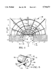
- FIG. 1 is a plan view of a tape bearing portion of a magnetic head illustrating the equipotentials, the flux lines and the contours of constant field strength generated in the transducing gap region of the head.
- FIG. 2A is a simplified top view depicting a gap portion of a typical dual finger record head, generating curved contours of constant magnetic field strength.
- FIG. 2B is a simplified view of a single magnetic recording made by the typical record head of FIG. 2A, depicting the curved ends impressed in the magnetic media at the edges of an associated track.
- FIG. 2C is a top view of a fragment of an azimuth recording format in a magnetic media generated by the typical record head of FIG. 2A and corresponding to the curved end recording of FIG. 2B, also depicting the overwriting of a previous track edge by the next track.
- FIG. 3A is a simplified top view depicting a gap portion of a single finger record head of the invention, generating straight contours of constant magnetic field strength at both sides of the head, and including the direction of head movement.
- FIG. 3B is a simplified view of a single magnetic recording made by the record head of FIG. 3A, depicting the lack of curved gap ends.
- FIG. 3C is a top view of a fragment of an azimuth recording format in a magnetic media generated by the invention record head of FIG. A and corresponding to the straight line recording of FIG. 3B.
- FIGS. 4A, 5A are simplified top views depicting gap portions of alternative embodiments of the record head of FIGS. 3A, 3C.
- FIGS. 4B, 5B are simplified views of a single magnetic recording made by the record heads of FIGS. 4A, 5A, respectively.
- FIG. 4C is a top view of a fragment of an azimuth recording format in a magnetic media generated by the invention record heads of FIGS. 4A or 5A.
- FIG. 6 is a simplified perspective view depicting a typical helical record/reproduce apparatus for moving a magnetic media relative to the magnetic head of, for example, FIGS. 3A, 4A or 5A.
- FIG. 1 is a plan view of a portion of a transducing gap 15 of a magnetic head 12 depicting the equipotentials (solid lines), flux lines (dashed lines) and contours of constant field strength (dotted lines) for conformal map solution to the finite gap head 12.
- the figure is taken from the publication "Theory of Magnetic Recording” by Neal Bertram, Cambridge University Press, chapter 3, page 69, which subject matter is specifically incorporated herein by reference.
- the associated graph illustrates the constant potentials V and flux lines U, as well as contours 14 of constant field strength at the surface of the head in the region of a magnetic media being transported past the gap 15 of the head.
- a fragment of a media 16 is illustrated with the head being moved in a direction 18 relative to the media.
- the left core edge is a trailing gap edge 20 and the right core edge is a leading gap edge 22.
- flux lines U that give the field direction do not coincide with the contours 14 of constant field strength.
- a field strength contour 14d is parallel with the x-axis while the field direction U is approximately at 60 degrees to the x-axis.
- the field contours 14 are generally circular and the field direction is along contours of constant strength.
- a contour 14a is the strongest and, along with other contours 14b, 14c most adjacent to the corners, define paths only in the regions of the respective gap edges 20,22. Contours progressively further from the gap edges decrease in constant field strength and, as depicted by contours 14d, 14e, 14f, etc., define paths which encompass both the trailing and leading edges 20,22 of the head.
- contour 14d extends further into the media (see point 24) at the gap edges than it does at the center of the gap length where, for example, the contour 14d dips towards the head surface.
- Contours 14f and the following contours however extend their furthest into the media in the region of the center or mid gap. Thus the region of maximum field follows along the gap edges to the ends of the gap, and past the ends of the gap the maximum field moves to the middle of the gap length.
- contours 14a-14c do not affect the magnetization in the media 16 since they do not penetrate into the media.
- contours 14c-14g are those most likely to be properly oriented, of sufficient depth and of a constant field strength equal to the field strength required to switch the magnetization in the media 16. These contours of switching strength extend across the transducing gap and past the facing edges or pole pieces to thereby encompass both the trailing and leading gap edges 20, 22.
- FIG. 2A is a top view of, for example, a portion of a conventional record head 26, including a pair of confronting magnetic material pole pieces or cores 28,30 which define therebetween a magnetic transducing gap 32.
- the gap includes a leading pole face 34 formed of a facing edge of the core 28 and a trailing pole face 36 formed of a facing edge of the core 30, corresponding to movement of the head in the direction shown by an arrow 34.
- the trailing edge of a record head provides the actual recording in a media.
- the facing pole faces of the cores or pole pieces are of equal narrow width and hereinafter may be alternatively termed "fingers".
- the head 26 is a "dual finger" record head.
- FIG. 2A further depicts several approximate contours 14 of constant magnetic field strength corresponding generally to the contours 14 of FIG. 1.
- the contours are generated by a typical record head at the recording surface of the head 26. It is assumed that the recording field at one of the depicted contours 14e-14g equals the field required to switch the magnetization in the adjacent magnetic media 16 (FIGS. 1 and 4). It may be seen that the path of the constant field strength contour in the media 16 where the record field is equal to the media switching field, follows an outwardly bulging curvature 38 at each end of the gap 32, that is, at the outside edges of the magnetic track. Referring in addition to FIG.
- a recording 40 defines a straight line 42 corresponding generally to the width of the gap, but further includes bent ends 44,46 whose curvatures correspond to the curvatures at points 48,50 respectively (FIG. 2A) of a contour 14e-14g generated by the trailing pole face 36 of the dual finger head 26.
- FIG. 2C illustrates a fragment of successive tracks A, B, A' recorded in a magnetic media in a conventional digital azimuth recording format.
- the tracks A, B are formed of successive recordings 40 with A, A' and B azimuth record heads (partially depicted at 52,54 respectively) recording the A and B tracks with alternate azimuths A and B.
- the A azimuth head leads the B azimuth head as they record in a direction 56, with the track A' subsequently following the track B on the next pass of the A azimuth head.
- the heads 52, 54 are wider than the width of the resulting recorded tracks and each subsequent pass of the record heads as they progress to the left of the page overwrites one edge of the previous adjacent track of the opposite azimuth in conventional fashion.
- the right side of the record head 26 is used to overlap, and thus over-write, a portion of the adjacent edge of the previous track.
- This side of the head thus is termed herein the "over-writing side" of the azimuth record head.
- This action erases the corresponding adjacent bent ends 44 of the previous recordings 40.
- the corresponding bent ends 46' and 46 of the head doing the overwriting remain recorded in the media.
- the resulting azimuth recording includes, for example, a track A whose right hand edge includes recordings with bent ends 46 and a track A' with recordings with bent ends 46. Note that the bent ends of tracks A and A' curve towards the direction of the B azimuth.
- the track B includes recordings with bent ends 46' which overwrite the bent ends 44 of the track A and which remain recorded in the magnetic media.
- the bent ends 46' of track B curve in a direction away from the direction of the A azimuth.
- the angle of azimuth rejection between the edge of the track B relative to the edge of the previous track A is greater than the angle of azimuth rejection between the track A or A' relative to the previous track B.
- the crosstalk of the A or A' channel into the B channel when the track B is read is greater than that of the B channel into the A channel when the track A or A' is read, which is an undesirable condition.
- the invention includes a "single finger" record head 58 including a pair of confronting magnetic material cores 60,62 which define therebetween, primarily due to the width of the core 60, a magnetic transducing gap 64.
- the orientation of the head and thus of the gap 64 relative to a direction 65 of head movement determines a gap leading pole face 66 formed of a facing edge of the core 60, and a gap trailing pole face 68 formed of a confronting portion of a facing edge of the core 62.
- the width of the facing pole face 66 of core 60 generally defines the width of the recorded tracks.
- the width of the facing edge of the core 62 is greater than the width of the facing edge of the core 60 and, in accordance with this embodiment of the invention, the head is oriented such that the trailing pole face 68 of the gap 64 corresponds to the wider core. Since the head of FIG. 3A has only one "finger” it is termed herein as a “single finger” record head.
- the overall width of the head 58 and thus of the core 62 may be about 100 to 125 micrometers ( ⁇ m) while the width of the core 60 may be about 40 ⁇ m.
- the gap length may be about 0.5 ⁇ m and the recorded track width may be about 20 m.
- the fabrication of the head is facilitated by making the core 62 the width of the head, since only the core 60 needs to be formed into the narrower finger configuration.
- the technique of this embodiment of the invention is satisfied equally well by a core 62 whose width is at least a gap length wider than the core 60.
- the core 62 is wider than core 60 by an amount greater than two gap lengths.
- FIG. 3A further depicts several approximate contours 14 of constant magnetic field strengths, which are the equivalent to the contours 14 of FIGS. 1, 2A, but which are generated by the record head 58 at the recording surface of the head and thus are modified in accordance with the invention.
- the recording field at one of the contours 14e-14g equals the field required to switch the magnetization in the adjacent magnetic media 16 (FIGS. 1, 6).
- the contour of constant field strength where it is equal to the media switching field, follows the trailing pole face 68 of the gap 64 and is therefore essentially straight.
- the switching contour of the invention record head 58 of FIG. 3A does not generate bent ends at the ends of an associated transition recording, particularly at the over-writing side of the record head.
- FIG. 3B depicts a transition recording 70 formed of a straight line 72 corresponding generally to the width of the core 58, that is, the width of the gap 64. Because gap 64. Because of the expanded facing dimension embodiment, the contour generated by the head 58 enters and exits the core 62 generally normal to the surface of the trailing pole face 68 of the core 62, and extends along a straight line corresponding to the trailing pole face 68. This head configuration forces the switching contour 14e-14g to have an expanded width relative to the width of the core 60 at the over-writing side of the head, whereby the gap's trailing edge, which performs the recording, likewise is widened at the over-writing side.
- FIG. 3C illustrates a fragment of successive tracks A, B recorded in a magnetic media in a digital azimuth recording format in accordance with the invention.
- the tracks A, B are formed of successive recordings 70 with A and B azimuth record heads (partially depicted at 76, 78 respectively) recording the A and B tracks with alternate azimuths A and B.
- the A azimuth head leads the B azimuth head as they record in the direction 77, with successive head passes proceeding to the left as in FIG. 2C.
- the extended trailing pole face 68 at the lagging side (the right side in this example) of the record head 58 provides the overlap of the previous adjacent track and comprises thus the overwriting side of the record head 58.
- the general media direction is illustrated via an arrow 80.
- FIG. 4A depicts a simplified structure of an alternative embodiment of the invention record head configuration of FIG. 3A.
- a record head 90 includes a pair of confronting magnetic material cores 92, 94 which define therebetween a magnetic transducing gap 96 when bonded together.
- the head is oriented so as to move in a direction 98 such that a pole face 100 of the core 92 forms a leading pole face and a pole face 102 of the core 94 forms a trailing pole face.
- the width of the core 92 generally defines the width of the gap and recorded tracks. If the successive passes of the head 90 proceed to the left, as depicted in FIGS. 2C, 3C, it follows that the right or lagging side of the head performs the function of over-writing new data over the adjacent edges of the previous track.
- the confronting cores 92, 94 of the head 90 of FIG. 4A are not symmetrically centered, but instead the trailing core 94 maintains an offset towards the over-writing side of the head 90 and the trailing core 94 is of relatively smaller width than the trailing core 62 of FIG. 3A. Since over-writing of the previous adjacent track is performed only by the over-writing side of the head, the relative configuration of the pole faces 100, 102 at the side of the head opposite the over-writing side, that is, the non-over-writing side, is not critical since any track curvatures generated by this corresponding non-over-writing edge of the track will be over-written and thus removed by the next pass of the head of alternate azimuth.
- the trailing pole face 102 need not extend laterally beyond the leading pole face 100 at the non-over-writing side as is necessary at the over-writing side of the head.
- the head 90 thus is depicted by way of example with the sides of the cores 92, 94 lying along a common plane 104, that is, generally are in register laterally.
- a condition to be met in such alternative embodiments employing trailing core widths that are only slightly wider, the same or even less than the leading core width, is that the width w of the transducing gap, that is, the recorded track width, is equal to or greater than the track pitch.
- Track pitch is the distance the head is moved laterally to record the next track, as shown in FIG. 4C.
- FIG. 4A further depicts several approximate contours 14 of constant magnetic field strengths which are equivalent to those of FIGS. 1, 2A, 3A.
- the contours in the region of the over-writing side of head 90 are similar to those of the invention as depicted in FIG. 3A, while the contours at the opposite side of the head are similar to those of the prior art head of FIG. 2A.
- the contour of constant field strength in the region of the over-writing side follows the straight trailing pole face 102 and likewise is straight with no bent ends in the corresponding transition recordings in the region of the over-writing side. This is shown in FIG.
- FIG. 4B which illustrates a transition recording 106 generated by the modified record head 90 and formed of a straight portion 108 with a straight end 110 in the region of the over-writing side, and a bent end 112 at the opposite non-over-writing side of the head 90.
- FIG. 4C wherein A and B azimuth tracks are formed of successive recordings 106, with A and B azimuth heads similar to the head of FIG. 4A, partially depicted at 114, 116, respectively, doing the recording.
- the straight ends 110 of the over-writing side of each head overlap the bent ends 112 of the previous adjacent track to produce straight transition recordings as depicted at 108 of the A track.
- the track pitch corresponding to the distance that the heads are moved laterally for each head scan is depicted at 120.
- the width w (FIG. 4A) of the transducing gap 96 should be equal to or greater than the track pitch 120.
- FIG. 5A illustrates a further modified structure of an alternative embodiment of the invention of FIGS. 3A, 4A.
- a modified record head 124 is depicted moving in a direction 125, wherein a trailing core 126 may be the same width, or may even be of narrower width, than a leading core 128.
- the trailing core 126 is arranged to maintain the offset laterally relative to the leading core 128 at the over-writing side of the record head 124, so that the transition recording generated by a trailing pole face 130 of core 126 extends laterally beyond a confronting leading pole face 132 of the core 128.
- a resulting transducing gap 134 is formed between the confronting portion of the faces 130, 132 to define a gap width w corresponding to the resulting recorded track width.
- the width w should be equal to or greater than the track pitch depicted in FIG. 4C.
- FIG. 5A depicts several approximate contours 14 of constant magnetic field strengths which are equivalent to those of FIGS. 1, 2A, 3A, 4A.
- the contours at the over-writing side of the record head 124 are similar to those of the invention of FIGS. 3A, 4A in that they follow the straight extended trailing pole face 130 to produce transition recordings 136 with a straight portion 138 and a straight end 140 at the over-writing side of the head 124 and thus at the over-writing end of the transition recording (FIG. 5B). Since the leading pole face 132 of core 128 extends beyond the trailing pole face 130 of core 126 at the non-over-writing side, the contours of constant magnetic field strengths are the inverse of the contours at the over-writing side of the head.
- FIG. 6 illustrates in simplified form by way of example only a helical scanning apparatus for generating a helically scanned azimuth recording format in a magnetic recording media 16.
- FIG. 6 depicts a pair of record heads 80, 82 similar to the single finger head 58 of FIG. 3A, or to the alternative record heads 90 or 124 of FIGS. 4A, 5A.
- the heads are mounted in an opposite azimuth configuration in a scanner head wheel 184 and are circumferentially spaced 180 degrees apart, with read heads 186, 188 spaced 90 degrees from the record heads.
- the record and read heads are precisely mounted in the scanner head wheel 184 by conventional head mounts which provide precision adjustments in the alignment of the heads as well as the rotation thereof to provide the several degrees of azimuth orientation.
- the magnetic media 16 is suitably wrapped about the head wheel 184 via a usual rotary scanner drum mechanism, shown in part at 190, whereby rotation of the head wheel 184 via a scanner motor 192 causes the record heads 180, 182 to record the tracks diagonally across the width of the magnetic media at a preselected angle relative to the length of the media.
- the single finger heads of FIG. 3A or the modified heads of FIGS. 4A, 5A are oriented relative to the direction of travel such that the trailing pole faces of the trailing cores on the over-writing side of the head, extend laterally beyond the respective leading pole faces of the leading cores.
- a capstan 194 is driven by a capstan motor (not shown) and provides the means for transporting the media relative to the drum mechanism 190 and head wheel 184. Although a media wrap angle of approximately 180 degrees is depicted in FIG. 6, other wrap angles or media orientation relative to the heads 180, 182, 186, 188 may be employed, as is well known in the art.
Abstract
Description
Claims (17)
Priority Applications (3)
| Application Number | Priority Date | Filing Date | Title |
|---|---|---|---|
| US08/660,355 US5710673A (en) | 1996-06-07 | 1996-06-07 | Azimuth record head for minimizing and equalizing crosstalk between tracks of opposite azimuths |
| EP97108964A EP0811965A3 (en) | 1996-06-07 | 1997-06-03 | An azimuth record head for minimizing and equalizing crosstalk between tracks of opposite azimuths |
| JP15142997A JP4080569B2 (en) | 1996-06-07 | 1997-06-09 | Azimuth recording head that minimizes or equalizes crosstalk between oppositely oriented tracks |
Applications Claiming Priority (1)
| Application Number | Priority Date | Filing Date | Title |
|---|---|---|---|
| US08/660,355 US5710673A (en) | 1996-06-07 | 1996-06-07 | Azimuth record head for minimizing and equalizing crosstalk between tracks of opposite azimuths |
Publications (1)
| Publication Number | Publication Date |
|---|---|
| US5710673A true US5710673A (en) | 1998-01-20 |
Family
ID=24649202
Family Applications (1)
| Application Number | Title | Priority Date | Filing Date |
|---|---|---|---|
| US08/660,355 Expired - Lifetime US5710673A (en) | 1996-06-07 | 1996-06-07 | Azimuth record head for minimizing and equalizing crosstalk between tracks of opposite azimuths |
Country Status (3)
| Country | Link |
|---|---|
| US (1) | US5710673A (en) |
| EP (1) | EP0811965A3 (en) |
| JP (1) | JP4080569B2 (en) |
Cited By (12)
| Publication number | Priority date | Publication date | Assignee | Title |
|---|---|---|---|---|
| US6947247B2 (en) | 2003-03-05 | 2005-09-20 | Advanced Research Corporation | Large angle azimuth recording and head configurations |
| US20090097155A1 (en) * | 1999-02-23 | 2009-04-16 | Advanced Research Corporation | Magnetic media having a servo track written with a patterned magnetic recording head |
| US20090262452A1 (en) * | 1999-12-30 | 2009-10-22 | Dugas Matthew P | Multichannel time based servo tape media |
| US20100027153A1 (en) * | 2008-03-28 | 2010-02-04 | Dugas Matthew P | Thin film planar arbitrary gap pattern magnetic head |
| US20100284105A1 (en) * | 2004-01-30 | 2010-11-11 | Dugas Matthew P | Apparatuses and methods for pre-erasing during manufacture of magnetic tape |
| US20100296192A1 (en) * | 1999-02-23 | 2010-11-25 | Advanced Research Corporation | Patterned magnetic recording head with termination pattern |
| US20100321824A1 (en) * | 2004-02-18 | 2010-12-23 | Dugas Matthew P | Magnetic recording head having secondary sub-gaps |
| US20110002065A1 (en) * | 2008-01-23 | 2011-01-06 | Dugas Matthew P | Recording heads with embedded tape guides and magnetic media made by such recording heads |
| US20110043940A1 (en) * | 2009-07-31 | 2011-02-24 | Gregory Lawrence Wagner | Erase drive system and methods of erasure for tape data cartridge |
| US20110141604A1 (en) * | 2004-05-04 | 2011-06-16 | Dugas Matthew P | Magnetic media formatted with an intergrated thin film subgap subpole structure for arbitrary gap pattern magnetic recording head |
| US8144424B2 (en) | 2003-12-19 | 2012-03-27 | Dugas Matthew P | Timing-based servo verify head and magnetic media made therewith |
| US9355679B1 (en) | 2013-11-08 | 2016-05-31 | Seagate Technology Llc | Transducer write field curvature characterization and compensation |
Citations (3)
| Publication number | Priority date | Publication date | Assignee | Title |
|---|---|---|---|---|
| US5296979A (en) * | 1988-09-20 | 1994-03-22 | Hitachi, Ltd. | Magnetic disc apparatus with thin film head suitable for high-density recording |
| US5442451A (en) * | 1982-02-22 | 1995-08-15 | Matsushita Electric Industrial Co., Ltd. | Helical scan recording/reproducing device for simultaneously helically recording/reproducing both video and audio signals |
| US5495375A (en) * | 1994-09-12 | 1996-02-27 | International Business Machines Corporation | Actuator arm assembly with self-locking arm |
Family Cites Families (5)
| Publication number | Priority date | Publication date | Assignee | Title |
|---|---|---|---|---|
| JPS5473615A (en) * | 1977-11-24 | 1979-06-13 | Sony Corp | Magnetic recording method |
| JPS62192905A (en) * | 1986-02-20 | 1987-08-24 | Victor Co Of Japan Ltd | Magnetic head |
| JPS63257904A (en) * | 1987-04-15 | 1988-10-25 | Pioneer Electronic Corp | Production of magnetic head |
| JPS6459610A (en) * | 1987-08-31 | 1989-03-07 | Fujitsu Ltd | Structure of magnetic head |
| JPH01124105A (en) * | 1987-11-10 | 1989-05-17 | Nec Corp | Magnetic head |
-
1996
- 1996-06-07 US US08/660,355 patent/US5710673A/en not_active Expired - Lifetime
-
1997
- 1997-06-03 EP EP97108964A patent/EP0811965A3/en not_active Withdrawn
- 1997-06-09 JP JP15142997A patent/JP4080569B2/en not_active Expired - Fee Related
Patent Citations (3)
| Publication number | Priority date | Publication date | Assignee | Title |
|---|---|---|---|---|
| US5442451A (en) * | 1982-02-22 | 1995-08-15 | Matsushita Electric Industrial Co., Ltd. | Helical scan recording/reproducing device for simultaneously helically recording/reproducing both video and audio signals |
| US5296979A (en) * | 1988-09-20 | 1994-03-22 | Hitachi, Ltd. | Magnetic disc apparatus with thin film head suitable for high-density recording |
| US5495375A (en) * | 1994-09-12 | 1996-02-27 | International Business Machines Corporation | Actuator arm assembly with self-locking arm |
Cited By (23)
| Publication number | Priority date | Publication date | Assignee | Title |
|---|---|---|---|---|
| US20090097155A1 (en) * | 1999-02-23 | 2009-04-16 | Advanced Research Corporation | Magnetic media having a servo track written with a patterned magnetic recording head |
| US20100296192A1 (en) * | 1999-02-23 | 2010-11-25 | Advanced Research Corporation | Patterned magnetic recording head with termination pattern |
| US7948705B2 (en) | 1999-12-30 | 2011-05-24 | Advanced Research Corporation | Method of making a multi-channel time based servo tape media |
| US20090262452A1 (en) * | 1999-12-30 | 2009-10-22 | Dugas Matthew P | Multichannel time based servo tape media |
| US20100002335A1 (en) * | 1999-12-30 | 2010-01-07 | Dugas Matthew P | Method of making a multi-channel time based servo tape media |
| US8542457B2 (en) | 1999-12-30 | 2013-09-24 | Advanced Research Corporation | Method of making a multi-channel time based servo tape media |
| US8437103B2 (en) | 1999-12-30 | 2013-05-07 | Advanced Research Corporation | Multichannel time based servo tape media |
| US8254052B2 (en) | 1999-12-30 | 2012-08-28 | Advanced Research Corporation | Method of making a multi-channel time based servo tape media |
| US6947247B2 (en) | 2003-03-05 | 2005-09-20 | Advanced Research Corporation | Large angle azimuth recording and head configurations |
| US8144424B2 (en) | 2003-12-19 | 2012-03-27 | Dugas Matthew P | Timing-based servo verify head and magnetic media made therewith |
| US20100284105A1 (en) * | 2004-01-30 | 2010-11-11 | Dugas Matthew P | Apparatuses and methods for pre-erasing during manufacture of magnetic tape |
| US20100321824A1 (en) * | 2004-02-18 | 2010-12-23 | Dugas Matthew P | Magnetic recording head having secondary sub-gaps |
| US8416525B2 (en) | 2004-05-04 | 2013-04-09 | Advanced Research Corporation | Magnetic media formatted with an intergrated thin film subgap subpole structure for arbitrary gap pattern magnetic recording head |
| US20110141604A1 (en) * | 2004-05-04 | 2011-06-16 | Dugas Matthew P | Magnetic media formatted with an intergrated thin film subgap subpole structure for arbitrary gap pattern magnetic recording head |
| US20110002065A1 (en) * | 2008-01-23 | 2011-01-06 | Dugas Matthew P | Recording heads with embedded tape guides and magnetic media made by such recording heads |
| US8068300B2 (en) | 2008-03-28 | 2011-11-29 | Advanced Research Corporation | Thin film planar arbitrary gap pattern magnetic head |
| US8068301B2 (en) | 2008-03-28 | 2011-11-29 | Advanced Research Corporation | Magnetic media formed by a thin film planar arbitrary gap pattern magnetic head |
| US8068302B2 (en) | 2008-03-28 | 2011-11-29 | Advanced Research Corporation | Method of formatting magnetic media using a thin film planar arbitrary gap pattern magnetic head |
| US20100027164A1 (en) * | 2008-03-28 | 2010-02-04 | Dugas Matthew P | Magnetic media formed by a thin planar arbitrary gap pattern magnetic head |
| US20100027153A1 (en) * | 2008-03-28 | 2010-02-04 | Dugas Matthew P | Thin film planar arbitrary gap pattern magnetic head |
| US20110043940A1 (en) * | 2009-07-31 | 2011-02-24 | Gregory Lawrence Wagner | Erase drive system and methods of erasure for tape data cartridge |
| US8767331B2 (en) | 2009-07-31 | 2014-07-01 | Advanced Research Corporation | Erase drive system and methods of erasure for tape data cartridge |
| US9355679B1 (en) | 2013-11-08 | 2016-05-31 | Seagate Technology Llc | Transducer write field curvature characterization and compensation |
Also Published As
| Publication number | Publication date |
|---|---|
| JP4080569B2 (en) | 2008-04-23 |
| EP0811965A2 (en) | 1997-12-10 |
| JPH10105903A (en) | 1998-04-24 |
| EP0811965A3 (en) | 1999-01-27 |
Similar Documents
| Publication | Publication Date | Title |
|---|---|---|
| US5535068A (en) | Helical scan method and apparatus for adjusting media speed to read non-native formats | |
| US5710673A (en) | Azimuth record head for minimizing and equalizing crosstalk between tracks of opposite azimuths | |
| US4390915A (en) | Helical scan type video tape recorder | |
| JPS623488B2 (en) | ||
| JPH10501091A (en) | Magnetic head and system for controlling position of magnetic head | |
| US4622614A (en) | Magnetic erasing head | |
| US3283085A (en) | Method and apparatus for recording and reproducing video and audio signal simultaneously on magnetic tape | |
| JPH10320720A (en) | Magnetic head for perpendicular recording | |
| US5227939A (en) | Scanning transducer having transverse information and control flux paths for reduced interference between fluxes | |
| US4691260A (en) | Tunnel erase magnetic head assembly | |
| EP0548503B1 (en) | Rotary head apparatus | |
| US6271990B2 (en) | Magnetic recording apparatus having a magnetic head for carrying out an overwrite operation | |
| JP2000132891A (en) | Rotary drum device, and magnetic recording and reproducing device | |
| US5864451A (en) | Magnetic tape head having longitudinal track width restriction grooves | |
| JP3265778B2 (en) | Magnetic disk drive | |
| KR870000043B1 (en) | Multi-track complex head | |
| JPH0546925A (en) | Magnetic head device | |
| US5067038A (en) | Rotary magnetic head device having two different kinds of heads | |
| JPH0326442B2 (en) | ||
| JP3532463B2 (en) | Magnetic recording / reproducing device | |
| JPH0744836A (en) | Rotary magnetic head and recording method for magnetic recording pattern | |
| JPH0132165Y2 (en) | ||
| JPS58164003A (en) | High density recording for wide band signal | |
| JPH0118494B2 (en) | ||
| JPH09245315A (en) | Magnetic head and magnetic recording and reproduing device |
Legal Events
| Date | Code | Title | Description |
|---|---|---|---|
| AS | Assignment |
Owner name: AMPEX CORPORATION, CALIFORNIA Free format text: ASSIGNMENT OF ASSIGNORS INTEREST;ASSIGNOR:VARIAN, GEORGE R.;REEL/FRAME:008025/0637 Effective date: 19960607 |
|
| FEPP | Fee payment procedure |
Free format text: PAYOR NUMBER ASSIGNED (ORIGINAL EVENT CODE: ASPN); ENTITY STATUS OF PATENT OWNER: LARGE ENTITY |
|
| STCF | Information on status: patent grant |
Free format text: PATENTED CASE |
|
| FPAY | Fee payment |
Year of fee payment: 4 |
|
| FEPP | Fee payment procedure |
Free format text: PAT HOLDER CLAIMS SMALL ENTITY STATUS, ENTITY STATUS SET TO SMALL (ORIGINAL EVENT CODE: LTOS); ENTITY STATUS OF PATENT OWNER: LARGE ENTITY |
|
| FEPP | Fee payment procedure |
Free format text: PAT HOLDER NO LONGER CLAIMS SMALL ENTITY STATUS, ENTITY STATUS SET TO UNDISCOUNTED (ORIGINAL EVENT CODE: STOL); ENTITY STATUS OF PATENT OWNER: LARGE ENTITY |
|
| REFU | Refund |
Free format text: REFUND - PAYMENT OF MAINTENANCE FEE, 8TH YR, SMALL ENTITY (ORIGINAL EVENT CODE: R2552); ENTITY STATUS OF PATENT OWNER: LARGE ENTITY |
|
| FPAY | Fee payment |
Year of fee payment: 8 |
|
| AS | Assignment |
Owner name: HILLSIDE CAPITAL INCORPORATED, NEW YORK Free format text: SECURITY AGREEMENT;ASSIGNOR:AMPEX CORPORATION;REEL/FRAME:021630/0230 Effective date: 20081003 |
|
| FPAY | Fee payment |
Year of fee payment: 12 |