US4890174A - Rotary voice coil micro-hard disk drive system - Google Patents
Rotary voice coil micro-hard disk drive system Download PDFInfo
- Publication number
- US4890174A US4890174A US07/029,056 US2905687A US4890174A US 4890174 A US4890174 A US 4890174A US 2905687 A US2905687 A US 2905687A US 4890174 A US4890174 A US 4890174A
- Authority
- US
- United States
- Prior art keywords
- drive system
- disk drive
- micro
- disk
- hard disks
- Prior art date
- Legal status (The legal status is an assumption and is not a legal conclusion. Google has not performed a legal analysis and makes no representation as to the accuracy of the status listed.)
- Expired - Lifetime
Links
Images


Classifications
-
- G—PHYSICS
- G11—INFORMATION STORAGE
- G11B—INFORMATION STORAGE BASED ON RELATIVE MOVEMENT BETWEEN RECORD CARRIER AND TRANSDUCER
- G11B5/00—Recording by magnetisation or demagnetisation of a record carrier; Reproducing by magnetic means; Record carriers therefor
- G11B5/012—Recording on, or reproducing or erasing from, magnetic disks
-
- G—PHYSICS
- G11—INFORMATION STORAGE
- G11B—INFORMATION STORAGE BASED ON RELATIVE MOVEMENT BETWEEN RECORD CARRIER AND TRANSDUCER
- G11B19/00—Driving, starting, stopping record carriers not specifically of filamentary or web form, or of supports therefor; Control thereof; Control of operating function ; Driving both disc and head
- G11B19/20—Driving; Starting; Stopping; Control thereof
-
- G—PHYSICS
- G11—INFORMATION STORAGE
- G11B—INFORMATION STORAGE BASED ON RELATIVE MOVEMENT BETWEEN RECORD CARRIER AND TRANSDUCER
- G11B25/00—Apparatus characterised by the shape of record carrier employed but not specific to the method of recording or reproducing, e.g. dictating apparatus; Combinations of such apparatus
- G11B25/04—Apparatus characterised by the shape of record carrier employed but not specific to the method of recording or reproducing, e.g. dictating apparatus; Combinations of such apparatus using flat record carriers, e.g. disc, card
- G11B25/043—Apparatus characterised by the shape of record carrier employed but not specific to the method of recording or reproducing, e.g. dictating apparatus; Combinations of such apparatus using flat record carriers, e.g. disc, card using rotating discs
-
- G—PHYSICS
- G11—INFORMATION STORAGE
- G11B—INFORMATION STORAGE BASED ON RELATIVE MOVEMENT BETWEEN RECORD CARRIER AND TRANSDUCER
- G11B5/00—Recording by magnetisation or demagnetisation of a record carrier; Reproducing by magnetic means; Record carriers therefor
- G11B5/48—Disposition or mounting of heads or head supports relative to record carriers ; arrangements of heads, e.g. for scanning the record carrier to increase the relative speed
- G11B5/54—Disposition or mounting of heads or head supports relative to record carriers ; arrangements of heads, e.g. for scanning the record carrier to increase the relative speed with provision for moving the head into or out of its operative position or across tracks
- G11B5/55—Track change, selection or acquisition by displacement of the head
- G11B5/5521—Track change, selection or acquisition by displacement of the head across disk tracks
Definitions
- the present invention relates to a hard disk drive system, in particular a micro-Winchester disk drive system.
- Winchester disk drives As replacements and enhancements to floppy disk drives for program storage.
- the Winchester disk drive in general provides higher capacities and faster speeds of operation, factors which are important for the effective use of personal computers running advanced software packages.
- Winchester disk drives that have developed in this regard were originally based on the use of hard disks of diameter of approximately 51/2 inch, also known as mini-Winchester disks, and this so called “51/4 inch” disk drive has generally developed as an "industry standard."
- Such a Winchester disk drive can store typically 5-30 Megabytes of information when designed around an open-loop positioning system using a stepper motor capable of supporting up to approximately 360 data tracks per inch.
- advances made by the assignee of the present invention have expanded the storage capacity of the typical 51/4 inch disk drive up to 600 tracks per inch using this same basic type of open-loop positioning system, a track density previously believed not to be obtainable with such a stepper motor technology.
- the assignee of the present invention has developed a 31/2 inch Winchester disk drive having 600 tracks per inch.
- closed-loop positioning systems have been developed for use with 51/4 Winchester disk drives. Such drives typically use a linear voice coil motor to provide motive force for the actuator for positioning the heads over the appropriate tracks. Such closed-loop positioning systems are capable of achieving much higher numbers of data tracks per inch.
- one such disk drive developed by the assignee of the present invention supports approximately 925 tracks per inch, with a resulting formatted storage capacity using a standard ST506/412 interface of approximately 5.3 Megabytes per disk surface. The positioning scheme of that disk drive is disclosed In the U.S. Pat. No. 4,638,384, issued Jan. 20, 1987.
- micro-Winchester disk drive As the software run on personal computers becomes more and more powerful and requires ever increasing amounts of media memory space, greater demand has been created for a micro-Winchester disk drive system having a large amount of data storage. Such disk drives are capable of storing such programs as well as providing fast access to the program and accompanying data for use by the central processing unit of the host microcomputer. At the same time, only a limited amount of physical space within the personal computer itself is required.
- a micro-Winchester disk drive typically measures 5.75" ⁇ 4.00" ⁇ 1.625" (1 ⁇ w ⁇ h). The larger the storage capacity and the smaller the access time of the disk drive, the more complex and more powerful the software that can be run on that drive and the faster that program and its data can be accessed by the host computer.
- Another object of the present invention is to provide an improved hard disk drive system in which the size, weight, sensitivity to vibrations, power consumption and heat dissipation are minimized without sacrificing high performance capabilities, thereby rendering the system particularly advantageous for use in portable computing systems.
- Still another object of the present invention is to provide a micro-Winchester disk drive with a closed-loop positioning system capable of providing performance parameters comparable to those of 51/4 inch Winchester disk drives and greater than those of existing 31/2" Winchester disk drives.
- a further object of the present invention is to provide a micro-Winchester disk drive system that affords storage capacity of at least approximately 9 megabytes per disk surface in its unformatted configuration and at least approximately 7 megabytes per disk surface in its formatted configuration.
- a still further object of the present invention is to provide a micro-Winchester disk drive system that is electrically compatible with 51/2 inch disk drives in its interface to host computer systems.
- a still further object of the present invention is to provide a micro-hard disk drive system in which the disk housing assembly is formed of two clamshell-shaped housing portions and in which the spindles which carry the positioning mechanism and the spindle motor are fixed thereto.
- Another object of the present invention is to provide a micro-Winchester disk drive system in which data is stored at a density of approximately 1040 tracks per inch.
- micro-Winchester disk drive system of the present invention was developed to provide a disk drive system particularly suited to meet the high storage demands of personal computer systems.
- the terminology, micro-Winchester disk refers to a Winchester disk of 85-100 mm in diameter, with the preferred embodiment being approximately 95 mm.
- a Winchester disk of this size is also referred to as a "31/2 inch” Winchester disk.
- the micro-Winchester disk drive system was developed to incorporate the 1040 tracks per inch closed-loop positioning capability. This new disk drive system, by virtue of its small size, high storage capacity, high positioner accuracy and vibration isolation, is ideally suited for use in personal computer systems, both desk top and portable.
- the disk drive system of the present invention is constructed for operating micro-Winchester computer disks.
- This disk drive system provides fast access data storage for use with small business computers, terminals and microprocessor-based systems, portable or otherwise, and in many other areas where compact, rugged and lightweight hard disk storage is required.
- the disk drive system of the present invention normally utilizes either two, three or four hard disks such as Winchester disks and provides data storage on each disk (except the servo disk) in excess of 14 megabytes, once the disks are formatted.
- the system is capable of storing in excess of 9 Megabytes per disk surface utilized with the disk unformatted.
- Each of the hard disks is mounted for rotation within the housing of the hard disk drive system of the present invention.
- each of those hard disks is 95 mm in diameter.
- a transducer which includes two read/write heads for each disk within the system, one head positioned on each side of the disk, writes digital information on and reads digital information from the hard disk.
- the transducer associated with that disk surface after the initial writing of the servo data during disk drive manufacture, is used only to read such servo data.
- the disk drive system of the present invention operates so that such information is stored on the disk at a density of approximately 1040 concentric tracks per inch.
- a positioning mechanism moves the transducer between the tracks on the computer disk for writing information on the disk and reading information from the disk.
- the positioning mechanism of the disk drive system of the present invention is arranged for moving the transducer along a path extending in an approximately radial direction with respect to the hard disk so that the transducer can move between the innermost and outermost tracks on the disk.
- the positioning mechanism moves the transducer along an arcuate path that extends in the radial direction with respect to the disk.
- the positioning mechanism of the disk drive system of the present invention also includes a voice coil motor and a rotary positioning mechanism connected thereto.
- a control signal is generated in a known manner, which causes such actuator to move the plurality of ganged heads from one track to the desired next track.
- One of the disk surfaces for example, in the preferred embodiment, the top surface of the top disk, is dedicated to storing servo signals for use with the closed-loop positioning system utilized by the disk drive system of the present invention.
- the head associated with such dedicated servo is normally enabled only to perform a read function, so as not to write over or erase the pre-recorded servo signals.
- a description of the servo signals and their use in operating the disk drive of the present invention is contained in concurrently filed U.S. patent application Ser. No. 854,825, entitled "Servo Positioning System For Disk Drive System, now U.S. Pat. No. 4,682,253 and” commonly assigned herewith. The disclosure of that application is incorporated herein.
- Each of the plurality of read/write heads of the transducer is arranged on one end of a flexure, which extends in a radial direction with respect to the disks.
- the other end of each flexure is arranged on one end of one of a plurality of fingers of a support arm.
- the support arm which includes the plurality of fingers, is pivotably attached to a spindle which is fixed to both of the clamshell-shaped pieces of the disk drive case. That arm spindle is located on one side of the support arm and is spaced away from the end of the arm which contains the fingers, flexures and heads.
- the support arm is designed to extend in a radial direction toward the disks.
- the flexures are attached to the support arm in a similar manner such that, when the support arm is in its fully counter-clockwise position, the heads are positioned over their respective disks.
- the rear portion of the support arm opposite the point of attachment of the flexures has attached thereto a rectangular coil which fits into the rotary voice coil assembly to provide a means of causing the support arm to pivot around its spindle so as to control the position of the heads. That pivoting of the support arm causes the heads to move back and forth over tracks of the disks.
- a solenoid operated lock is also provided for securing the positioning mechanism in its fully-clockwise position, with the heads at the extreme inside of the disks when the drive is powered-off. Thus, damage to the disk surfaces from head bounce or other causes when the drive is not in operation is prevented.
- the disk drive system of the present invention is contained in a housing in which the micro-hard disks, the transducers and the entire positioning mechanism are contained. That housing is constructed of two clamshell-shaped pieces, one top and one bottom piece. An air filtration system is utilized to maintain the "clean" nature of the Winchester hard-disk assembly (HDA). Shock and vibration reduction supports are also provided so as to minimize the transmission of shock and vibration from the host personal computer to the housing.
- a housing in which the micro-hard disks, the transducers and the entire positioning mechanism are contained. That housing is constructed of two clamshell-shaped pieces, one top and one bottom piece.
- An air filtration system is utilized to maintain the "clean" nature of the Winchester hard-disk assembly (HDA). Shock and vibration reduction supports are also provided so as to minimize the transmission of shock and vibration from the host personal computer to the housing.
- Each of the from two to four hard disks is rigidly mounted to the hub of a spindle drive motor.
- Ferrofluidic and labyrinth seals are fitted to the respective drive motor bearings in order to prevent contamination of the HDA.
- the entire spindle drive motor is contained within the HDA and is rigidly mounted to both clamshell-shaped housing pieces which contain the drive.
- the motor spindle by means of bearings which allow the hub to rotate around the spindle, is fixedly mounted to the drive housing, thus still allowing the motor to rotate.
- Such a mounting structure as well as the provision of mounting the rotary voice coil actuator to an actuator spindle fixedly secured at both sides of the clamshell-shaped housing members, provides an increased rigidity which enables the use of two clamshell-shaped sections for incorporating the HDA.
- the use of two clamshell-shaped sections for the housing provides for an ease of assembly and servicing heretofore unknown in the disk drive industry.
- the electronics of the micro-Winchester disk drive system of the present invention have been developed utilizing integrated circuits.
- the entire control circuit is arranged on a single printed circuit board.
- Providing electronic functions of the drive on a single printed circuit board whose dimensions do not exceed the overall dimensions of the drive permits the drive to be used in applications which in the past were limited to only the much larger mini or 51/4 Winchester disk drive systems.
- the electronic functions have been implemented using intergrated circuit chips of different types using surface mounting technology, on a six layer circuit board, with the objective of functioning with a minimum use of power.
- FIG. 1 is a side perspective view of the housing of the disk drive system of the present invention mounted within its frame assembly;
- FIG. 2 is a top perspective view of the disk drive system of the present invention with the top housing piece removed to disclose the contents of the drive;
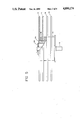
- FIG. 3 is a side view of the rotary voice coil positioning mechanism of the disk drive system of the present invention.
- FIG. 4 is a bottom view of the disk drive system of the present invention.
- FIG. 5 is a side view of the fixed spindle rotating hub drive motor, with disks attached, used in the disk drive system of the present invention.
- FIG. 6 is a functional block diagram of the control circuit for use with the disk drive system of the present invention.
- FIG. 1 A micro-Winchester disk drive system in accordance with the present invention is shown in FIG. 1.
- the disk drive system includes a housing 2 comprised of top and bottom clamshell-shaped pieces 2a and 2b, which is mounted in turn within a frame 4.
- Frame 4 is attached to a face plate, or facia, 6.
- Face plate 6, with housing 2 and frame 4 may be slid into a slot provided within the host computer for the disk drive system.
- a plurality of anti-vibration mounts 8 are provided in order to secure the housing 2 and hence the internal operating members of the disk drive system against vibrational forces.
- the disk drive system of FIG. 1 may readily be mounted in a standard 31/2 Winchester disk drive mounting space.
- micro-Winchester disk drive system of the present invention within a larger opening constructed for receiving a 51/2 inch disk drive system.
- FIG. 2 of commonly assigned U.S. Pat. No. 4,568,988, entitled “Micro-Hard Disk Drive System” the housing 2 with frame 4 is placed inside of a second frame.
- the second frame is attached to a larger face plate and to the first frame 4.
- a second series of anti-vibration mounts can be provided between first and second frames for further isolating the disk drive system against shock and vibrational forces in directions both parallel and orthogonal to the direction of isolation provided by the first set of anti-vibration mounts.
- the disk drive system in accordance with the preferred embodiment of the present invention is a microprocessor-based device which receives and transmits MFM (modified frequency modulation) data, seeking the appropriate track in response to step pulses across the disk control interface.
- MFM modified frequency modulation
- a typical format scheme with 256 data bytes per sector and 32 sectors per track can realize an efficiency of about 79% giving formatted capacities up to about 50 Megabytes.
- the microprocessor is responsible for the control of the voice coil motor used for head positioning. Fast seek times are achieved by the use of programmed velocity profiles.
- a three-phase brushless D.C. motor rotating at 3600 r.p.m. is used for driving the disks at a constant speed. Hall effect devices are used for commutation of the motor windings and for motor speed control.
- the motor may preferably be of a fixed spindle, rotating hub variety. Ferrofluidic and labryinth seals are fitted to the drive motor bearings in order to prevent contamination of the HDA.
- FIG. 2 A top perspective view of the disk drive system of the present invention is shown in FIG. 2.
- four micro-Winchester disks, 14, 16, 18 and 20 are arranged on the hub 22 of a D.C. motor 24 for rotation within the housing 2.
- Magnetic heads 26, 28, 30, 32, 34, 36, 38 and 40 are attached to flexures 42 which are attached to fingers 44 which are formed as a part of the support arm 46.
- That support arm forms part of the positioning mechanism 48 which is rotated about a fixed arm spindle 50 by means of a rectangular coil 52 attached thereto.
- the coil 52 is mounted in such a manner that it is driven by voice coil motor 54.
- a breather filter 56 is provided on the top half of the disk housing adjacent to the center of the top hub plate 60 of the D.C. spindle motor 24.
- a recirculating filter 62 is located inside the HDA chamber 64 in a suitable position to filter the flow of air resulting from the pumping effect of the rotating disks when the disk drive is in operation.
- the top casing 2a seals the enclosure by means of a continuous gasket 3 positioned between itself and the bottom casing 2b.
- An electronics board 66 is fixed to the bottom casing and covers the full area of this face of the disk drive.
- the D.C. motor 24 has its center spindle 12 fixed to the bottom half 2b of the disk drive unit by means of a press fit.
- the top of the spindle 12 is fixedly mounted to the upper casing half 2a by suitable means such as a screw 58.
- the positioning mechanism 48 is shown in greater detail in FIG. 3. That positioning mechanism 48 is mounted on the base of the lower housing 2b within chamber 64 of the disk drive system. Chamber 64 is formed by the lower housing 2b and upper housing 2a. A plurality of Winchester disks are mounted on the hub assembly 22 of the D.C. spindle motor 24 within chamber 64 so that they are rotated within the chamber by the D.C. motor.
- the arm spindle 50 about which the support arm 46 rotates, is fixedly connected to the upper housing 2a by a screw 59 and to the lower housing by a nut 86.
- the typical read/write magnetic head 26 is mounted on one end 42a of a flexure 42, which serves to support it over the disk surface.
- the other end 42b of flexure 42 is attached to a finger 44 of a support arm 46.
- the flexure 42 is a thin rectangular stainless steel foil.
- the positioning arm 46 is rotatably mounted to the steel spindle shaft 50 by means of grub screws (not shown) and rides on suitable bearings (not shown) thereon.
- the support arm 46 is angled towards the disk such that, together with an additional angle provided by the fingers 44 of the support arm 46, the heads are placed in their proper position. Such construction ensures that the heads are always over the disk surfaces, even at both extreme positions of travel of the positioning mechanism 48.
- a rectangularly-shaped rotary voice coil motor 54 is mounted to the lower casing 2b of the disk drive system adjacent to the end of the positioning arm 46 opposite the magnetic heads.
- the rectangular coil 52 attached to that end of the arm 46 is arranged to cut the magnetic force field created by the voice coil motor 54 such that it causes the positioning mechanism 48 to rotate about the fixed spindle shaft 50.
- the support arm assembly 46 is statically balanced about the actuator spindle 50. Positioning is accomplished by means of a closed-loop servo control system which uses information derived from a dedicated servo surface recorded on, in the preferred embodiment, the top surface of the upper-most disk.
- An electrical interface between the heads and the electronics board is provided by means of a flat flexi-circuit 74 which incorporates separate pre-amplifier circuits for the servo head and the data heads.
- the electronics circuit board contains all circuitry necessary to implement read/write and head selection, motor speed control, closed-loop positioner controller, host controller interface (ST 506/412) and microprocessor.
- the microprocessor which is provided with 4k bytes of memory storage, for example, by means of a ROM, provides a full automatic power-up sequence with diagnostics; motor speed control check to ⁇ 1% during power up and regular motor speed control checks to +10%, -5% after power-up; control of the output lines from the disk drive system and latching upon detected fault conditions; voice-coil positioner control, including mode select and velocity ramp generation and fault code indication by means of codes in a front panel LED 5.
- An index pulse is derived from information recorded on the dedicated servo surface once per revolution.
- the D.C. motor 24 which drives the disks is of the rotating hub, fixed shaft type and is of a brushless 3-phase design.
- the hub 22 and electromagnets rotate around the fixed shaft 12, riding upon a pair of bearings, one near the top and the other near the bottom of the shaft.
- a ferrofludic seal is provided on the outside of the bottom bearing and a labyrinth seal is provided on the outside of the upper bearing.
- a series of three Hall sensors are contained on a flexi-circuit mounted on the bottom casing 2b for commutation purposes.
- the bottom of the shaft 12 is fixedly attached to the bottom casing 2b of the drive, by a press fit in socket 84 in the preferred embodiment.
- the upper end of the shaft contains inner threads to which a screw 58 is secured, through the upper casing 2a.
- a solenoid-operated lock 25 is provided adjacent to the support arm portion 46 of the positioning mechanism 48.
- a pin support 78 is formed on the opposite side of the support arm 46 away from the disks, which has a pin 80 affixed thereto.
- a generally triangularly-shaped locking member 82 is pivotably attached to the solenoid locking assembly 76. It is also attached to the moving shaft of the solenoid, but is spring-loaded such that when power is applied to the solenoid, the solenoid shaft must work against the spring tension to remove the locking member from its locked position to its unlocked position. In its locked position, the heads are held at the inner radius of the disks, in order to prevent damage to the HDA.
- the electronic circuits were designed primarily as integrated circuits that are placed on a single printed circuit board 66.
- the use of only a single printed circuit board whose dimensions lie within the outline dimensions of the housing 2, is particularly beneficial in enabling the drive to be used in personal computers in which space is at a premium, for example, in portable computers, as well as providing an anti-vibration mounting arrangement to be utilized for mounting the micro-Winchester disk drive system. Consequently, an extremely rugged, low weight, hard disk drive system is provided for use in a portable computer.
- the development of the single printed circuit board electronic control circuit in the present micro-Winchester disk drive system has enabled the power consumption and dissipation to be significantly reduced.
- the electronic circuitry in the preferred embodiment provides heat dissipation at a rate of about 12 watts as compared to 25 watts typically dissipated by 51/4 inch Winchester disk drive systems.
- the micro-Winchester disk drive system of the present invention dissipates a relatively small amount of heat in the computer system. That enables a portable computer either to utilize a smaller fan or to eliminate the use of a fan for removing heat from the system.
- FIG. 5 A functional block diagram illustrating the functional operation of the disk drive of the present invention is shown in FIG. 5.
- the spindle motor 24 is provided with a source of 12 v D.C. power which causes the disk assembly attached to its hub 22 to rotate at 3600 r.p.m..
- the three Hall sensors used for commutation purposes are contained on a flexi-circuit 101 mounted to the bottom casing, as described previously. Those Hall sensors provide signals indicative of the motor speed and position to a motor speed controller 103 which applies the proper phases of signal at the proper rate to cause the motor to rotate at the desired speed.
- the solenoid shipping latch is actuated and unlatches the positioner mechanism.
- the servo head reads the pre-recorded servo signals from the dedicated servo disk and transmits them through a preamplifier on servo flexi circuit 102 and servo demodulator 120 to the servo controller 104 and, through the control logic ULA 106, to the microprocessor 108.
- the microprocessor provides the functions described previously, by means of firmware stored, for example, in a ROM 124.
- the firmware 124 contains a look-up table which generates the velocity profiles used during such operations, as well as routines for the power-up sequences and fault monitoring.
- the microprocessor also communicates with the drive interface 112 which is itself in communication with the host computer (not shown) through, for example, a standard ST 506/412 interface 114.
- That host interface 114 provides and receives data and control signals.
- the data signals pass through a data channel 116.
- the read data is pre-amplified in the circuity contained in the read/write flexi-circuit 118, which provides its output to the data channel 116.
- the data to be written on the disks is transmitted through the drive interface 112 directly to the read/write flexi-circuit 118 where it is written on the selected one of disks 100 by means of the appropriate enabled data head.
- the position of the heads on the disks is controlled by means of the microprocessor 108, through the control logic ULA 106 and the servo controller 104 connected to that control logic.
- the microprocessor 108 buffers step pulses from the drive interface 112 to the voice coil motor 54.
- the interface step rate determines the seek mode automatically.
- the microprocessor accelerates the voice coil motor such that an average access time of 30 ms is achieved
- the average access time is defined as the total time for all possible cylinder accesses divided by the number of all possible cylinder accesses.
Abstract
Description
______________________________________ GENERAL PERFORMANCE ______________________________________ Disks per2,3,4 drive 4,6,8 Unformatted capacity 27.26, 46.21, 63.59 (Megabytes) Formatted capacity (typical) Per drive (Megabytes) 21.43, 35.71, 50.00 Per track (bytes) 8192 Per sector (bytes) 256 Sectors per Heads track 32 Cylinders 672 Transfer rate (M bits/s) 5 Seek times (ms) (including settling) Track to track 7 Average 30Maximum 60 Average latency (ms) 8.3 Bit density (max) 15,072 bits per inch Track density (max) 1040 tracks per inch Rotational speed (r.p.m.) 3600 + 10%, -5% ______________________________________ SHOCK & VIBRATION ______________________________________ SHOCK Operating 10 g 10 ms duration peak acceleration Non-Operating 50g VIBRATION Operating 5 Hz to 500 Hz 1.0 g acceleration Non-operating 5 Hz to 500 Hz 2.0 g acceleration ______________________________________
Claims (14)
Priority Applications (1)
| Application Number | Priority Date | Filing Date | Title |
|---|---|---|---|
| US07/029,056 US4890174A (en) | 1986-04-23 | 1987-03-18 | Rotary voice coil micro-hard disk drive system |
Applications Claiming Priority (2)
| Application Number | Priority Date | Filing Date | Title |
|---|---|---|---|
| US85494986A | 1986-04-23 | 1986-04-23 | |
| US07/029,056 US4890174A (en) | 1986-04-23 | 1987-03-18 | Rotary voice coil micro-hard disk drive system |
Related Parent Applications (1)
| Application Number | Title | Priority Date | Filing Date |
|---|---|---|---|
| US85494986A Continuation | 1986-04-23 | 1986-04-23 |
Publications (1)
| Publication Number | Publication Date |
|---|---|
| US4890174A true US4890174A (en) | 1989-12-26 |
Family
ID=26704476
Family Applications (1)
| Application Number | Title | Priority Date | Filing Date |
|---|---|---|---|
| US07/029,056 Expired - Lifetime US4890174A (en) | 1986-04-23 | 1987-03-18 | Rotary voice coil micro-hard disk drive system |
Country Status (1)
| Country | Link |
|---|---|
| US (1) | US4890174A (en) |
Cited By (24)
| Publication number | Priority date | Publication date | Assignee | Title |
|---|---|---|---|---|
| WO1991002349A1 (en) * | 1989-07-31 | 1991-02-21 | Conner Peripherals, Inc. | Architecture for 2-1/2 inch diameter single disk drive |
| WO1991006947A1 (en) * | 1989-11-03 | 1991-05-16 | Conner Peripherals, Inc. | Multiple actuator disk drive |
| US5025335A (en) * | 1989-07-31 | 1991-06-18 | Conner Peripherals, Inc. | Architecture for 21/2 inch diameter single disk drive |
| WO1992001283A1 (en) * | 1990-07-06 | 1992-01-23 | Conner Peripherals, Inc. | Low height disk drive |
| WO1992009077A1 (en) * | 1990-11-09 | 1992-05-29 | Conner Peripherals, Inc. | Multiple actuator disk drive |
| WO1993010531A1 (en) * | 1991-11-22 | 1993-05-27 | Conner Peripherals, Inc. | Small size constant torque voice coil motor |
| US5235482A (en) * | 1989-11-09 | 1993-08-10 | Rodime Plc | Magnetic disk drive incorporating a mechanically damped base |
| US5245487A (en) * | 1989-01-27 | 1993-09-14 | International Business Machines Corporation | Transducer head for rigid disk drive |
| US5255136A (en) * | 1990-08-17 | 1993-10-19 | Quantum Corporation | High capacity submicro-winchester fixed disk drive |
| US5298839A (en) * | 1990-09-10 | 1994-03-29 | Fujitsu Limited | Electrical angle control system for a brushless DC motor in a magnetic disk apparatus |
| US5319622A (en) * | 1990-02-09 | 1994-06-07 | Ast Research, Inc. | Control and information disk for disk recording system |
| US5400196A (en) * | 1992-04-30 | 1995-03-21 | International Business Machines Corporation | DASD with spindle imbalance isolation and method for producing same |
| WO1995015552A1 (en) * | 1993-12-01 | 1995-06-08 | Maxtor Corporation | Disk drive employing adaptive read/write channel for optimizing head-media-channel performance |
| US5600514A (en) * | 1993-09-24 | 1997-02-04 | Fujitsu Limited | Magnetic disk drive including labyrinth seal and magnetic seal |
| US5600219A (en) * | 1994-03-14 | 1997-02-04 | Seagate Technology, Inc. | Sensorless closed-loop actuator unlatch |
| US5600517A (en) * | 1991-07-10 | 1997-02-04 | Seagate Technology, Inc. | Magnet/block assembly for disc drive systems |
| US5621582A (en) * | 1988-01-25 | 1997-04-15 | Conner Peripherals, Inc. | Disk drive including a baseplate well for the spin motor |
| US5841997A (en) * | 1995-09-29 | 1998-11-24 | Emc Corporation | Apparatus for effecting port switching of fibre channel loops |
| US5847896A (en) * | 1988-01-25 | 1998-12-08 | Conner Peripherals, Inc. | Disk drive including sloped base and cover |
| US6229676B1 (en) | 1998-11-13 | 2001-05-08 | International Business Machines Corporation | Ferrofluid seal for actuator bearing |
| US6429999B1 (en) | 1988-01-25 | 2002-08-06 | Seagate Technology Llc | Pre-assembled voice coil magnetic assembly and rotatable attachment structure/method to base plate for disc drive |
| US6999909B1 (en) | 1999-10-28 | 2006-02-14 | Seagate Technology Llc | Process for designing an optimal vibration isolation mount for a disc drive |
| US20060044748A1 (en) * | 2004-08-31 | 2006-03-02 | Connelly Donald M Jr | Apparatus, system, and method for reducing rotational vibration transmission within a data storage system |
| US20100296198A1 (en) * | 2009-05-20 | 2010-11-25 | Sae Magnetics (Hk) Ltd. | Sub-assembly for a hard disc drive |
Citations (11)
| Publication number | Priority date | Publication date | Assignee | Title |
|---|---|---|---|---|
| GB1342495A (en) * | 1971-03-13 | 1974-01-03 | Ibm | Transducer arms for magnetic disc recording and or reproducing apparatus |
| GB2073501A (en) * | 1980-02-29 | 1981-10-14 | Digital Equipment Corp | Rotary actuator assembly for disc drive head positioner |
| GB2100050A (en) * | 1981-05-22 | 1982-12-15 | Philips Nv | Carrying-arm arrangement for a magnetic-disc storage apparatus |
| GB2127610A (en) * | 1982-09-30 | 1984-04-11 | Kennedy Company | Magnetic disc transducer arm |
| US4535372A (en) * | 1983-06-29 | 1985-08-13 | Storage Technology Corporation | Position tracking servo control systems and methods |
| EP0151256A1 (en) * | 1984-02-07 | 1985-08-14 | Siemens Aktiengesellschaft | Housing for magnetic disc memory with two sided bearing for the disc stack |
| US4638383A (en) * | 1984-02-22 | 1987-01-20 | Mcginlay James G | Micro hard-disk drive system |
| US4639863A (en) * | 1985-06-04 | 1987-01-27 | Plus Development Corporation | Modular unitary disk file subsystem |
| US4669004A (en) * | 1986-02-27 | 1987-05-26 | Quantum Corporation | High capacity disk file with embedded sector servo |
| US4689703A (en) * | 1984-02-07 | 1987-08-25 | Siemens Aktiengesellschaft | Positioning device for a magnetic disk memory |
| US4712146A (en) * | 1985-06-04 | 1987-12-08 | Plus Development Corporation | Thin and compact micro-Winchester head and disk assembly |
-
1987
- 1987-03-18 US US07/029,056 patent/US4890174A/en not_active Expired - Lifetime
Patent Citations (14)
| Publication number | Priority date | Publication date | Assignee | Title |
|---|---|---|---|---|
| GB1342495A (en) * | 1971-03-13 | 1974-01-03 | Ibm | Transducer arms for magnetic disc recording and or reproducing apparatus |
| US3849800A (en) * | 1971-03-13 | 1974-11-19 | Ibm | Magnetic disc apparatus |
| GB2073501A (en) * | 1980-02-29 | 1981-10-14 | Digital Equipment Corp | Rotary actuator assembly for disc drive head positioner |
| GB2100050A (en) * | 1981-05-22 | 1982-12-15 | Philips Nv | Carrying-arm arrangement for a magnetic-disc storage apparatus |
| GB2127610A (en) * | 1982-09-30 | 1984-04-11 | Kennedy Company | Magnetic disc transducer arm |
| US4535372A (en) * | 1983-06-29 | 1985-08-13 | Storage Technology Corporation | Position tracking servo control systems and methods |
| EP0151256A1 (en) * | 1984-02-07 | 1985-08-14 | Siemens Aktiengesellschaft | Housing for magnetic disc memory with two sided bearing for the disc stack |
| US4689703A (en) * | 1984-02-07 | 1987-08-25 | Siemens Aktiengesellschaft | Positioning device for a magnetic disk memory |
| US4714972A (en) * | 1984-02-07 | 1987-12-22 | Siemens Aktiengesellschaft | Housing for a magnetic disk memory having a disk pack seat at opposite sides of the disk pack |
| US4638383A (en) * | 1984-02-22 | 1987-01-20 | Mcginlay James G | Micro hard-disk drive system |
| US4638383B1 (en) * | 1984-02-22 | 1988-11-29 | ||
| US4639863A (en) * | 1985-06-04 | 1987-01-27 | Plus Development Corporation | Modular unitary disk file subsystem |
| US4712146A (en) * | 1985-06-04 | 1987-12-08 | Plus Development Corporation | Thin and compact micro-Winchester head and disk assembly |
| US4669004A (en) * | 1986-02-27 | 1987-05-26 | Quantum Corporation | High capacity disk file with embedded sector servo |
Non-Patent Citations (9)
| Title |
|---|
| Electronic Engineering Times Winchester Disk Drives Clements, 2/25/85, Issue 318 pp. 53,56,58,59,60,62,63,65. * |
| Electronics International, vol. 56, No. 5, 3/10/83 pp. 139 142. * |
| Electronics International, vol. 56, No. 5, 3/10/83 pp. 139-142. |
| Hewlett Packard brochure for HP97501A, "31/2" 10 mbyte micro-Winchester Disc Drive", 11/1/84. |
| Hewlett Packard brochure for HP97501A, 3 10 mbyte micro Winchester Disc Drive , 11/1/84. * |
| IEEE Trans on Magnetics vol. mag. 17, No. 4, "Mechanical and Servo Design of a 10 inch Disk Drive" Mizoshita et al., 7/81, pp. 1387-1391. |
| IEEE Trans on Magnetics vol. mag. 17, No. 4, Mechanical and Servo Design of a 10 inch Disk Drive Mizoshita et al., 7/81, pp. 1387 1391. * |
| Plus, "Hardcard-the easy-to-use 10 Megabyte Hard Disk Drive On A Plug-in Card", 1985. |
| Plus, Hardcard the easy to use 10 Megabyte Hard Disk Drive On A Plug in Card , 1985. * |
Cited By (33)
| Publication number | Priority date | Publication date | Assignee | Title |
|---|---|---|---|---|
| US5621582A (en) * | 1988-01-25 | 1997-04-15 | Conner Peripherals, Inc. | Disk drive including a baseplate well for the spin motor |
| US6429999B1 (en) | 1988-01-25 | 2002-08-06 | Seagate Technology Llc | Pre-assembled voice coil magnetic assembly and rotatable attachment structure/method to base plate for disc drive |
| US5847896A (en) * | 1988-01-25 | 1998-12-08 | Conner Peripherals, Inc. | Disk drive including sloped base and cover |
| US5245487A (en) * | 1989-01-27 | 1993-09-14 | International Business Machines Corporation | Transducer head for rigid disk drive |
| US5808830A (en) * | 1989-07-31 | 1998-09-15 | Conner Peripherals. Inc. | Architecture for 2-1/2 inch diameter single disk drive |
| US5025335A (en) * | 1989-07-31 | 1991-06-18 | Conner Peripherals, Inc. | Architecture for 21/2 inch diameter single disk drive |
| WO1991002349A1 (en) * | 1989-07-31 | 1991-02-21 | Conner Peripherals, Inc. | Architecture for 2-1/2 inch diameter single disk drive |
| WO1991006947A1 (en) * | 1989-11-03 | 1991-05-16 | Conner Peripherals, Inc. | Multiple actuator disk drive |
| US5223993A (en) * | 1989-11-03 | 1993-06-29 | Conner Peripherals, Inc. | Multiple actuator disk drive |
| US5293282A (en) * | 1989-11-03 | 1994-03-08 | Conner Peripherals, Inc. | Multiple actuator disk drive |
| US5235482A (en) * | 1989-11-09 | 1993-08-10 | Rodime Plc | Magnetic disk drive incorporating a mechanically damped base |
| US5319622A (en) * | 1990-02-09 | 1994-06-07 | Ast Research, Inc. | Control and information disk for disk recording system |
| EP0903741A2 (en) * | 1990-07-06 | 1999-03-24 | Seagate Technology, Inc. | Low height disk drive |
| EP0903741A3 (en) * | 1990-07-06 | 1999-04-14 | Seagate Technology, Inc. | Low height disk drive |
| WO1992001283A1 (en) * | 1990-07-06 | 1992-01-23 | Conner Peripherals, Inc. | Low height disk drive |
| US5255136A (en) * | 1990-08-17 | 1993-10-19 | Quantum Corporation | High capacity submicro-winchester fixed disk drive |
| US5298839A (en) * | 1990-09-10 | 1994-03-29 | Fujitsu Limited | Electrical angle control system for a brushless DC motor in a magnetic disk apparatus |
| WO1992009077A1 (en) * | 1990-11-09 | 1992-05-29 | Conner Peripherals, Inc. | Multiple actuator disk drive |
| US5600517A (en) * | 1991-07-10 | 1997-02-04 | Seagate Technology, Inc. | Magnet/block assembly for disc drive systems |
| WO1993010531A1 (en) * | 1991-11-22 | 1993-05-27 | Conner Peripherals, Inc. | Small size constant torque voice coil motor |
| US5400196A (en) * | 1992-04-30 | 1995-03-21 | International Business Machines Corporation | DASD with spindle imbalance isolation and method for producing same |
| US5600514A (en) * | 1993-09-24 | 1997-02-04 | Fujitsu Limited | Magnetic disk drive including labyrinth seal and magnetic seal |
| US5995305A (en) * | 1993-12-01 | 1999-11-30 | Maxtor Corporation | Disk drive using off-track margin to obtain optimal performance parameters |
| US6404570B1 (en) | 1993-12-01 | 2002-06-11 | Maxtor Corporation | Disk drive with adaptive channel optimization |
| WO1995015552A1 (en) * | 1993-12-01 | 1995-06-08 | Maxtor Corporation | Disk drive employing adaptive read/write channel for optimizing head-media-channel performance |
| US5600219A (en) * | 1994-03-14 | 1997-02-04 | Seagate Technology, Inc. | Sensorless closed-loop actuator unlatch |
| US5841997A (en) * | 1995-09-29 | 1998-11-24 | Emc Corporation | Apparatus for effecting port switching of fibre channel loops |
| US6229676B1 (en) | 1998-11-13 | 2001-05-08 | International Business Machines Corporation | Ferrofluid seal for actuator bearing |
| US6999909B1 (en) | 1999-10-28 | 2006-02-14 | Seagate Technology Llc | Process for designing an optimal vibration isolation mount for a disc drive |
| US20060044748A1 (en) * | 2004-08-31 | 2006-03-02 | Connelly Donald M Jr | Apparatus, system, and method for reducing rotational vibration transmission within a data storage system |
| US7259966B2 (en) | 2004-08-31 | 2007-08-21 | International Business Machines Corporation | Apparatus, system, and method for reducing rotational vibration transmission within a data storage system |
| US20100296198A1 (en) * | 2009-05-20 | 2010-11-25 | Sae Magnetics (Hk) Ltd. | Sub-assembly for a hard disc drive |
| US8331059B2 (en) | 2009-05-20 | 2012-12-11 | Sae Magnetics (Hk) Ltd. | Sub-assembly for a hard disc drive |
Similar Documents
| Publication | Publication Date | Title |
|---|---|---|
| US4890174A (en) | Rotary voice coil micro-hard disk drive system | |
| US4568988A (en) | Micro hard-disk drive system | |
| US4638383A (en) | Micro hard-disk drive system | |
| US5293282A (en) | Multiple actuator disk drive | |
| US6594117B2 (en) | Disc drive magnetic latch mechanism | |
| US4772974A (en) | Compact head and disk assembly | |
| EP0556287B1 (en) | High performance disk drive architecture | |
| US5422767A (en) | Vibration damper for a multiple disk drive unit | |
| EP0560298A2 (en) | Micro miniature hard disk drive | |
| EP0614564A1 (en) | Microminiature hard disk drive | |
| EP0505363A1 (en) | Multiple actuator disk drive. | |
| US4757406A (en) | High capacity disk drive | |
| US5243479A (en) | Mounting structure for information recording and reproducing apparatus | |
| US5060095A (en) | Head-disk enclosure assembly for a magnetic disk storage device | |
| GB2190531A (en) | 3 <1>/2 inch Winchester disc drive | |
| US5995312A (en) | High capacity disk drive | |
| US7149052B2 (en) | Screw attachment from exterior of disk drive enclosure for motors with mount bracket screw bolt pattern diameter larger than the motor hub outside diameter | |
| JP3472394B2 (en) | Disk unit | |
| US6456454B1 (en) | Head disc assembly having low internal air pressure | |
| JP2753220B2 (en) | Information recording / reproducing device | |
| KR20010051052A (en) | Disk drive apparatus and hard disk drive | |
| EP0530217A4 (en) | Thin line micro hard disk architecture | |
| WO1994022133A1 (en) | High capacity two and one-half inch disk drive | |
| KR19990024491A (en) | Noise reduction method and device in hard disk drive |
Legal Events
| Date | Code | Title | Description |
|---|---|---|---|
| STCF | Information on status: patent grant |
Free format text: PATENTED CASE |
|
| AS | Assignment |
Owner name: BANK OF SCOTLAND Free format text: SECURITY INTEREST;ASSIGNOR:RODIME PLC;REEL/FRAME:005808/0907 Effective date: 19900928 |
|
| FEPP | Fee payment procedure |
Free format text: PAT HOLDER CLAIMS SMALL ENTITY STATUS - SMALL BUSINESS (ORIGINAL EVENT CODE: SM02); ENTITY STATUS OF PATENT OWNER: LARGE ENTITY |
|
| FEPP | Fee payment procedure |
Free format text: PAYOR NUMBER ASSIGNED (ORIGINAL EVENT CODE: ASPN); ENTITY STATUS OF PATENT OWNER: LARGE ENTITY |
|
| FEPP | Fee payment procedure |
Free format text: PAT HLDR NO LONGER CLAIMS SMALL ENT STAT AS SMALL BUSINESS (ORIGINAL EVENT CODE: LSM2); ENTITY STATUS OF PATENT OWNER: LARGE ENTITY |
|
| FPAY | Fee payment |
Year of fee payment: 4 |
|
| FPAY | Fee payment |
Year of fee payment: 8 |
|
| FPAY | Fee payment |
Year of fee payment: 12 |
|
| AS | Assignment |
Owner name: QED INTELLECTUAL PROPERTY SERVICES LIMITED, ENGLAN Free format text: ASSIGNMENT OF ASSIGNORS INTEREST;ASSIGNOR:SPORTECH PLC;REEL/FRAME:012333/0356 Effective date: 20010711 |
|
| AS | Assignment |
Owner name: SPORTECH PLC., UNITED KINGDOM Free format text: RELEASE OF SECURITY INTEREST;ASSIGNOR:BANK OF SCOTLAND;REEL/FRAME:013933/0259 Effective date: 20030407 Owner name: SPORTECH, PLC., UNITED KINGDOM Free format text: CHANGE OF NAME;ASSIGNOR:RODIME, PLC.;REEL/FRAME:013933/0257 Effective date: 20000915 Owner name: SPORTECH, PLC., UNITED KINGDOM Free format text: TERMINATION OF LICENSE AGREEMENT;ASSIGNOR:QED INTELLECTUAL PROPERTY LTD.;REEL/FRAME:013933/0266 Effective date: 20030404 |
|
| AS | Assignment |
Owner name: MAXTOR CORPORATION, CALIFORNIA Free format text: ASSIGNMENT OF ASSIGNORS INTEREST;ASSIGNOR:SPORTECH, PLC;REEL/FRAME:014242/0332 Effective date: 20030702 Owner name: RS PATENT HOLDING CORP., DELAWARE Free format text: ASSIGNMENT OF ASSIGNORS INTEREST;ASSIGNOR:SPORTECH, PLC;REEL/FRAME:014242/0332 Effective date: 20030702 |
|
| AS | Assignment |
Owner name: JPMORGAN CHASE BANK, N.A., AS ADMINISTRATIVE AGENT Free format text: SECURITY AGREEMENT;ASSIGNORS:MAXTOR CORPORATION;SEAGATE TECHNOLOGY LLC;SEAGATE TECHNOLOGY INTERNATIONAL;REEL/FRAME:022757/0017 Effective date: 20090507 Owner name: WELLS FARGO BANK, NATIONAL ASSOCIATION, AS COLLATE Free format text: SECURITY AGREEMENT;ASSIGNORS:MAXTOR CORPORATION;SEAGATE TECHNOLOGY LLC;SEAGATE TECHNOLOGY INTERNATIONAL;REEL/FRAME:022757/0017 Effective date: 20090507 |
|
| AS | Assignment |
Owner name: SEAGATE TECHNOLOGY HDD HOLDINGS, CALIFORNIA Free format text: RELEASE;ASSIGNOR:JPMORGAN CHASE BANK, N.A., AS ADMINISTRATIVE AGENT;REEL/FRAME:025662/0001 Effective date: 20110114 Owner name: SEAGATE TECHNOLOGY LLC, CALIFORNIA Free format text: RELEASE;ASSIGNOR:JPMORGAN CHASE BANK, N.A., AS ADMINISTRATIVE AGENT;REEL/FRAME:025662/0001 Effective date: 20110114 Owner name: MAXTOR CORPORATION, CALIFORNIA Free format text: RELEASE;ASSIGNOR:JPMORGAN CHASE BANK, N.A., AS ADMINISTRATIVE AGENT;REEL/FRAME:025662/0001 Effective date: 20110114 Owner name: SEAGATE TECHNOLOGY INTERNATIONAL, CALIFORNIA Free format text: RELEASE;ASSIGNOR:JPMORGAN CHASE BANK, N.A., AS ADMINISTRATIVE AGENT;REEL/FRAME:025662/0001 Effective date: 20110114 |
|
| AS | Assignment |
Owner name: SEAGATE TECHNOLOGY INTERNATIONAL, CAYMAN ISLANDS Free format text: TERMINATION AND RELEASE OF SECURITY INTEREST IN PATENT RIGHTS;ASSIGNOR:WELLS FARGO BANK, NATIONAL ASSOCIATION, AS COLLATERAL AGENT AND SECOND PRIORITY REPRESENTATIVE;REEL/FRAME:030833/0001 Effective date: 20130312 Owner name: SEAGATE TECHNOLOGY US HOLDINGS, INC., CALIFORNIA Free format text: TERMINATION AND RELEASE OF SECURITY INTEREST IN PATENT RIGHTS;ASSIGNOR:WELLS FARGO BANK, NATIONAL ASSOCIATION, AS COLLATERAL AGENT AND SECOND PRIORITY REPRESENTATIVE;REEL/FRAME:030833/0001 Effective date: 20130312 Owner name: EVAULT INC. (F/K/A I365 INC.), CALIFORNIA Free format text: TERMINATION AND RELEASE OF SECURITY INTEREST IN PATENT RIGHTS;ASSIGNOR:WELLS FARGO BANK, NATIONAL ASSOCIATION, AS COLLATERAL AGENT AND SECOND PRIORITY REPRESENTATIVE;REEL/FRAME:030833/0001 Effective date: 20130312 Owner name: SEAGATE TECHNOLOGY LLC, CALIFORNIA Free format text: TERMINATION AND RELEASE OF SECURITY INTEREST IN PATENT RIGHTS;ASSIGNOR:WELLS FARGO BANK, NATIONAL ASSOCIATION, AS COLLATERAL AGENT AND SECOND PRIORITY REPRESENTATIVE;REEL/FRAME:030833/0001 Effective date: 20130312 |