EP2717266A1 - Write pole tip with trailing edge recess - Google Patents
Write pole tip with trailing edge recess Download PDFInfo
- Publication number
- EP2717266A1 EP2717266A1 EP13187580.9A EP13187580A EP2717266A1 EP 2717266 A1 EP2717266 A1 EP 2717266A1 EP 13187580 A EP13187580 A EP 13187580A EP 2717266 A1 EP2717266 A1 EP 2717266A1
- Authority
- EP
- European Patent Office
- Prior art keywords
- data
- data writer
- recess
- trailing edge
- sloped surfaces
- Prior art date
- Legal status (The legal status is an assumption and is not a legal conclusion. Google has not performed a legal analysis and makes no representation as to the accuracy of the status listed.)
- Withdrawn
Links
Images


Classifications
-
- G—PHYSICS
- G11—INFORMATION STORAGE
- G11B—INFORMATION STORAGE BASED ON RELATIVE MOVEMENT BETWEEN RECORD CARRIER AND TRANSDUCER
- G11B5/00—Recording by magnetisation or demagnetisation of a record carrier; Reproducing by magnetic means; Record carriers therefor
- G11B5/008—Recording on, or reproducing or erasing from, magnetic tapes, sheets, e.g. cards, or wires
-
- G—PHYSICS
- G11—INFORMATION STORAGE
- G11B—INFORMATION STORAGE BASED ON RELATIVE MOVEMENT BETWEEN RECORD CARRIER AND TRANSDUCER
- G11B5/00—Recording by magnetisation or demagnetisation of a record carrier; Reproducing by magnetic means; Record carriers therefor
- G11B5/127—Structure or manufacture of heads, e.g. inductive
- G11B5/1278—Structure or manufacture of heads, e.g. inductive specially adapted for magnetisations perpendicular to the surface of the record carrier
-
- G—PHYSICS
- G11—INFORMATION STORAGE
- G11B—INFORMATION STORAGE BASED ON RELATIVE MOVEMENT BETWEEN RECORD CARRIER AND TRANSDUCER
- G11B5/00—Recording by magnetisation or demagnetisation of a record carrier; Reproducing by magnetic means; Record carriers therefor
- G11B5/127—Structure or manufacture of heads, e.g. inductive
- G11B5/187—Structure or manufacture of the surface of the head in physical contact with, or immediately adjacent to the recording medium; Pole pieces; Gap features
-
- G—PHYSICS
- G11—INFORMATION STORAGE
- G11B—INFORMATION STORAGE BASED ON RELATIVE MOVEMENT BETWEEN RECORD CARRIER AND TRANSDUCER
- G11B5/00—Recording by magnetisation or demagnetisation of a record carrier; Reproducing by magnetic means; Record carriers therefor
- G11B5/127—Structure or manufacture of heads, e.g. inductive
- G11B5/31—Structure or manufacture of heads, e.g. inductive using thin films
- G11B5/3109—Details
- G11B5/3116—Shaping of layers, poles or gaps for improving the form of the electrical signal transduced, e.g. for shielding, contour effect, equalizing, side flux fringing, cross talk reduction between heads or between heads and information tracks
Definitions
- Various embodiments of the present disclosure are generally directed to a data writer that is capable of data recording.
- a write pole tip may be configured with leading and trailing edges on opposite sides of a tip body.
- the trailing edge can be shaped by a recess that extends into the tip body towards the leading edge.
- a data writer comprising a write pole tip with leading and trailing edges on opposite sides of a tip body, the trailing edge shaped by a recess extending into the tip body towards the leading edge.
- the trailing edge is configured as a v-shape.
- the recess shapes at least two protrusions on the trailing edge.
- the recess provides a plurality of sloped surfaces.
- At least two of the plurality of sloped surfaces are angled with respect to the leading edge.
- At least two of the plurality of sloped surfaces meet at a midpoint of the tip body.
- At least two of the plurality of sloped surfaces connect via a median surface configured parallel to the leading edge.
- the recess is symmetrical about a central plane of the tip body.
- the recess is asymmetrical about a central plane of the tip body.
- the leading and trailing edges are respectively connected by side surfaces
- the recess may define a single continuously curvilinear surface along the trailing edge.
- the write pole tip is configured to program data to a bit patterned media.
- the tip body is sized to cover a plurality of adjacent data tracks present on a data storage media.
- the write pole tip is configured to conduct shingled data recording to the adjacent data tracks.
- a magnetic element comprising a write pole tip with leading and trailing edges on opposite sides of a tip body, the trailing edge shaped into two protrusions by a recess extending into the tip body towards the leading edge, the two protrusions defined by first and second sloped surfaces each extending at a common angle with respect to the leading edge towards a central plane of the tip body.
- the first and second sloped surfaces each extend beyond a width of the leading edge.
- the first and second sloped surfaces are continuously linear.
- first and second sloped surfaces are angled to half a predetermined skew angle with respect to the leading edge.
- an apparatus comprising: a write pole tip with leading and trailing edges on opposite sides of a tip body; and means for mitigating skew angle errors.
- the means for mitigating skew angle errors comprises a plurality of sloped surfaces angled with respect to the leading edge to form a recess extending into the tip body towards the leading edge.
- bit patterned media has emerged as providing increased areal bit density while maintaining data integrity.
- rotating bit patterned media can encounter difficulty in accommodating rotated transitions as patterned bit arrays do not self-assemble into skewed configurations.
- Such uniform patterned bit arrays can limit data bit writing times and reduce performance for data storage devices when data bits are being accessed from extreme skew angles.
- the data storage industry is motivated to provide a data storage device capable of maximizing data storage capacity and data transfer rates with bit patterned media, especially in high skew angle operation.
- a write pole tip may be configured with leading and trailing edges on opposite sides of a tip body where the trailing edge is shaped by a recess that extends into the tip body towards the leading edge.
- the shaped recess may allow the write pole tip to be better aligned with data bits at extreme regions of a data medium where the pole tip is skewed.
- the ability to tune the shape of the recess can provide pole tip configurations that increase the efficiency and reliability of programming data by accommodating for pole tip skew angle.
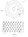
- FIG. 1 provides a top block representation of an example portion of a data storage device 100. It will be understood, however, that the various embodiments of this disclosure are not so limited by the environment shown in FIG. 1 and can be implemented to perform data access operations in a variety of data storage devices.
- the device 100 may be configured with one or more rotating data media 102 centrally attached and controlled by a spindle motor 104.
- User accessible data bits (not shown), and other non-user accessible data such as grey code, can be aligned along concentric data tracks 106 that are accessed individually or concurrently by an actuating assembly 108.
- the actuating assembly 108 is displayed in accordance with various embodiments to include a load beam 110 that rotates to position a slider 112 proximal to one or more data tracks 106.
- the rotation of the media 102 can generate an air bearing on which the slider 112 flies and positions a head gimbal assembly (HGA) to allow a transducing portion of the HGA to access one or more data bits.
- HGA head gimbal assembly
- the slider 112 and HGA can include one or more transducing elements, such as a magnetic writer and/or magnetically responsive reader, which operate to program and read data from the storage media 102, respectively.
- controlled motion of the actuating assembly 108 induces the transducers to align with the data tracks 106 to write, read, and rewrite data.
- Movement of the actuating assembly 108 to position the slider 112 proximal to selected data bits can tilt the orientation of the HGA with a "skew angle" that may affect the alignment of the transducing elements in relation to the data tracks 106.
- the skew angle can introduce angular offset between the magnetic field profile used to access data bits and the data bits themselves, which reduces the timing margin available for reading or writing data to/from the data bits.
- angular offset to a data storage device 100 can be particularly difficult to correct when the media 102 is configured as a bit patterned media where data bits are constructed as granular islands locked into predetermined positions on the media 102.
- the increase in data bit density and reduction in data track 106 width can further exacerbate the effects of skew angle on data bit access as the physical size of data writing elements are difficult to reduce and the timing margins face faster transfer rates per inch of media 102 space.
- shingled data recording can be employed to allow physically larger transducing elements to program multiple data bits from adjacent data tracks 106 concurrently.
- FIG. 2 displays a portion of an example data storage media 120 capable of being used in the data storage device 100 of FIG. 1 .
- the data storage media 120 is configured as a bit patterned media where columnar bits 122 are constructed into a recording layer of the media 120, as opposed to non-bit patterned media where data bits are programmed anywhere on a recording layer.
- a plurality of adjacent data bits 122 are grouped into data tracks (Track 1-6) that can be individually or concurrently read, but sequentially programmed with a data write pole that physically spans multiple tracks. That is, a write pole that is physically larger than a single data track can be used to program a multiple data tracks by sequentially programming multiple adjacent tracks in succession. As such, a write pole would program follow paths 1-3 in sequence to produce six distinctly programmed data tracks.
- FIG. 2 are shown to be linear, such configuration is not required or limited as various data track shapes, such as curvilinear, can be used.
- FIG. 3 generally shows a block representation of how skew angle can correspond to misalignment of a data write pole with bit patterned data bits 132.
- Data write pole tip 134 illustrates proper alignment of the trapezoidal shaped tip with data bits 132 from adjacent data tracks 136. Proper alignment of the pole tip 134 is defined as a trailing edge 140 that is substantially orthogonal to the data tracks, which allows for efficient and reliable switching of pole tip 134 magnetization in the area 135 between data bits 132.
- pole tips 142 and 144 In contrast to the aligned write pole tip 134, pole tips 142 and 144 have roughly a seven degree skew angle, either positive or negative, that induces a tilted pole tip trailing edge with respect to a plane perpendicular to the direction of movement for the pole tips.
- the tilted trailing edge of pole tips 142 and 144 show how a slight skew angle can reduce the amount of time in which the pole tips can switch magnetizations due to the trailing edge 140 being in contact with multiple data bits 132 for a longer amount of time than when no skew angle is present. That is, the tilt of write pole tips 142 and 144 respectively changes the time the write pole trailing edge is not engaging a data bit, which stresses magnetization switching time in the pole tip.
- skew angle of can be approximately fourteen degrees or more.
- Write pole tips 146 and 148 respectively show how such positive and negative skew angle can further change the extremity of trailing edge contact with data bits 132, which further reduces the timing available to program a magnetic domain.
- an increased skew angle corresponds to a tilted trailing edge that reduces the amount of time the trialing edge 140 can change magnetization without inadvertently programming an already accessed data bit 132.
- the write pole 160 shown in FIG. 4 can be constructed with a trailing edge tuned to mitigate the effects of skew angle.
- the example write pole 160 is merely illustrative of one possible configuration that mitigates skew angle difficulties and is by no means limiting or required.
- the write pole 160 is displayed from an air bearing and shows a write pole tip 162 disposed between a pair of side shields 164, a leading shield 166, and a trailing shield 168.
- the write pole tip 162 has leading and trailing edges 170 and 172 that are connected by side edges oriented at one or more predetermined angles ⁇ 1 with respect to the Y axis.
- the width 176 of the leading edge 170 and the angular orientation of the side edges 174 can provide a number of different shapes, such as trapezoids, rectangles, polygons, and rhomboids, that can be selectively used at will. Regardless of the shape of the leading and side edges 170 and 174, increased skew angle can reduce the time in which the trailing edge 172 is between data bits, as shown in FIG. 3 .
- the trailing edge 172 can be tuned to a predetermined shape defined by a recess that extends from the trailing edge 172 towards the leading edge 170.
- the recess can be shaped in a variety of different fabrication and design characteristics that provide multiple trailing edge protrusions 178 respectively adapted to mitigate extreme positive and negative skew angle tilt. While the protrusions 178 can be independently shaped with differing parameters, the recess shown in FIG. 4 is shaped substantially as a "V" where the protrusions 178 are each defined by a surface sloped at a predetermined angle ⁇ 2 with respect to the X axis.
- FIG. 5 provides a general illustration of how the trailing edge of an example write pole tip can be tuned to mitigate large skew angle data bit programming.
- a v-shaped trailing edge can be configured so that data bits 192 of multiple data tracks can be efficiently programmed at a zero skew angle despite have a slightly reduced overall pole tip length, as measured from the leading edge to the trailing edge.
- pole tip 190 is at large skew angles, such as pole tip 194 tilted at the extreme positive skew angle and pole tip 196 positioned at the extreme negative skew angle.
- the shaped recess of the trailing edge of each pole tip 194 and 196 provide protrusions angled in opposite directions to orient an outer portion of the trailing edge perpendicular with the data track for both positive and negative skew angles.
- the orientation of the sloped surfaces of the trailing edge allows the pole tips 194 and 196 to engage the data bits 192 with maximum time to switch magnetizations between data bits than if the trailing edge was not shaped, as shown in FIG. 3 .
- FIGS. 4 and 5 are not required or limited as various tuned trailing edge recess shapes can produce a variety of symmetrical and asymmetrical protrusions.
- FIGS. 6A-6C respectively show example write pole tips 192, 194, and 196 that have uniquely tuned trailing edges illustrative of the diverse tuning possibilities provided by a shaped trailing edge recess.
- recess 198 is shaped as an asymmetrical "V" defined by trailing surfaces 200 and 202 sloped at differing angles to a pinnacle 204 offset from a plane 206 positioned about the midpoint of the pole tip 192.
- the asymmetrical recess 198 can provide protrusions tuned to mitigate specific skew angles, data track widths, and data bit densities that may vary for different regions of a data storage media.
- FIG. 6B displays a recess 210 configured in a "V" shape symmetrical about a central plane 212.
- recess 210 is shaped to two sloped surfaces 214 and 216 joined by a median surface 218 that is substantially parallel to the leading surface 220 of the pole tip 194.
- the inclusion of the median surface 218 may increase data programming with little to no skew angle as a portion of the trailing surface matches the shape of the non-magnetic space between data bits when the pole tip is skewed.
- FIG. 6C shows another "V" shaped recess 230 symmetrical about a central plane 232.
- the recess 230 is formed by a continuously curvilinear surface 234 that can allow for simplified manufacturing while reducing the risk of magnetic shunting between the pole tip and adjacent magnetic shields, such as shield 168 of FIG. 4 .
- the shapes of the various recesses 198, 210, and 230 can be combined and modified, at will, to provide sloped surfaces adapted to mitigate skew angle misalignment between the trailing edge and data bits of adjacent data tracks.
- FIG. 7 provides an example data writer fabrication routine 240 performed in accordance with various embodiments.
- the routine 240 may begin by designing a trailing edge recess in step 242.
- the expected skew angle range, data bit density, and data track width can all be assessed to provide a trailing edge with multiple protrusions capable of mitigating skew angle effects for positive and negative skew angle write pole orientations.
- the trailing edge recess is designed to have protrusions angled at roughly half the largest encountered skew angle to allow for skew angle effect mitigation across a wide skew angle spectrum.
- step 244 forms a write pole with a pole body having leading and trailing edges.
- the pole body may have a general shape, like a trapezoid, where the leading edge has a narrow width that connects to the trailing edge via angled side surfaces.
- Various embodiments form a write pole body with an average width that is roughly twice the width of a data track.
- step 246 begins constructing the trailing edge recess by removing predetermined portions of the trailing edge, such as with etching.
- decision 248 evaluates if the trailing edge recess design of step 242 is present in the write pole tip and whether additional removal is necessary.
- an asymmetric trailing edge recess may correspond with more than one removal step in contrast to a continuously curvilinear recess that could be formed with only one removal step. If indeed more material is to be removed to form the designed trailing edge recess, step 250 proceeds to remove the additional portions.
- step 252 then forms magnetic shields about the write pole tip to construct a functional data writer, which can be implemented in a data transducing head that is suspended from a slider, such as slider 112 of FIG. 1 .
- a data writer can be constructed with a trailing edge tuned to mitigate skew angle effects.
- the routine 240 is not limiting as the steps and decisions shown in FIG. 7 can be omitted, changed, and added.
- a bit patterned media can be evaluated for data bit size, density, and data track width prior to step 242 to allow a trailing edge recess that precisely accommodates a data media.
- the various structural configurations of the trailing edge recess can allow a write pole tip to efficiently program data over a wide variety of skew angles without having to adjust data bit timing or media rotation speed. Additionally, the ability to tune the trailing edge recess provides the ability to shape the trailing edge to accommodate different skew angle, data bit density, and data track width environments. While the embodiments have been directed to magnetic recording, it will be appreciated that the claimed technology can readily be utilized in any number of other applications, such as 1707data sensing.
Abstract
Description
- Various embodiments of the present disclosure are generally directed to a data writer that is capable of data recording.
- In accordance with some embodiments, a write pole tip may be configured with leading and trailing edges on opposite sides of a tip body. The trailing edge can be shaped by a recess that extends into the tip body towards the leading edge.
- According to a first aspect of the present invention, there is provided a data writer comprising a write pole tip with leading and trailing edges on opposite sides of a tip body, the trailing edge shaped by a recess extending into the tip body towards the leading edge.
- Preferably, the trailing edge is configured as a v-shape.
- Preferably, the recess shapes at least two protrusions on the trailing edge.
- Preferably, the recess provides a plurality of sloped surfaces.
- In this case, it is also preferable that at least two of the plurality of sloped surfaces are angled with respect to the leading edge.
- It is also preferable that at least two of the plurality of sloped surfaces meet at a midpoint of the tip body.
- It is also preferably that at least two of the plurality of sloped surfaces connect via a median surface configured parallel to the leading edge.
- Preferably, the recess is symmetrical about a central plane of the tip body. Alternatively, the recess is asymmetrical about a central plane of the tip body. Preferably, the leading and trailing edges are respectively connected by side surfaces The recess may define a single continuously curvilinear surface along the trailing edge. Preferably, the write pole tip is configured to program data to a bit patterned media. Preferably, the tip body is sized to cover a plurality of adjacent data tracks present on a data storage media.
- In this case, it is preferred that the write pole tip is configured to conduct shingled data recording to the adjacent data tracks.
- According to another aspect of the present invention, there is provided a magnetic element comprising a write pole tip with leading and trailing edges on opposite sides of a tip body, the trailing edge shaped into two protrusions by a recess extending into the tip body towards the leading edge, the two protrusions defined by first and second sloped surfaces each extending at a common angle with respect to the leading edge towards a central plane of the tip body.
- Preferably, the first and second sloped surfaces each extend beyond a width of the leading edge.
- Preferably, the first and second sloped surfaces are continuously linear.
- In this case, it is preferred that the first and second sloped surfaces are angled to half a predetermined skew angle with respect to the leading edge.
- According to a yet further aspect of the present invention, there is provided an apparatus comprising: a write pole tip with leading and trailing edges on opposite sides of a tip body; and means for mitigating skew angle errors.
- Preferably, the means for mitigating skew angle errors comprises a plurality of sloped surfaces angled with respect to the leading edge to form a recess extending into the tip body towards the leading edge.
- Embodiments of the present invention will now be described by way of further example only and with reference to the accompanying drawings, in which:
-
FIG. 1 is a block representation of an example portion of a data storage device. -
FIG. 2 provides a top view block representation of a portion of the data storage device displayed inFIG. 1 . -
FIG. 3 shows an example block representation of a portion of an example data sensor capable of being used in the data storage device ofFIG. 1 . -
FIG. 4 displays a block representation of a portion of an example read sensor constructed in accordance with various embodiments. -
FIG. 5 illustrates an isometric view of a portion of an example magnetic element constructed in accordance with various embodiments. -
FIGS. 6A-6C show a top view of an example two dimensional data read sensor constructed capable of being used in the data storage device ofFIG. 1 . -
FIG. 7 provides a flowchart of a data writer fabrication routine conducted in accordance with various embodiments. - The data storage industry continues to strive for devices with higher data capacity and faster data access. As data bits and data tracks become smaller, bit patterned media has emerged as providing increased areal bit density while maintaining data integrity. However, rotating bit patterned media can encounter difficulty in accommodating rotated transitions as patterned bit arrays do not self-assemble into skewed configurations. Such uniform patterned bit arrays can limit data bit writing times and reduce performance for data storage devices when data bits are being accessed from extreme skew angles. Thus, the data storage industry is motivated to provide a data storage device capable of maximizing data storage capacity and data transfer rates with bit patterned media, especially in high skew angle operation.
- Accordingly, a write pole tip may be configured with leading and trailing edges on opposite sides of a tip body where the trailing edge is shaped by a recess that extends into the tip body towards the leading edge. The shaped recess may allow the write pole tip to be better aligned with data bits at extreme regions of a data medium where the pole tip is skewed. The ability to tune the shape of the recess can provide pole tip configurations that increase the efficiency and reliability of programming data by accommodating for pole tip skew angle.
-
FIG. 1 provides a top block representation of an example portion of adata storage device 100. It will be understood, however, that the various embodiments of this disclosure are not so limited by the environment shown inFIG. 1 and can be implemented to perform data access operations in a variety of data storage devices. - The
device 100 may be configured with one or morerotating data media 102 centrally attached and controlled by aspindle motor 104. User accessible data bits (not shown), and other non-user accessible data such as grey code, can be aligned alongconcentric data tracks 106 that are accessed individually or concurrently by anactuating assembly 108. Theactuating assembly 108 is displayed in accordance with various embodiments to include aload beam 110 that rotates to position aslider 112 proximal to one ormore data tracks 106. - In operation, the rotation of the
media 102 can generate an air bearing on which theslider 112 flies and positions a head gimbal assembly (HGA) to allow a transducing portion of the HGA to access one or more data bits. While not limiting, theslider 112 and HGA can include one or more transducing elements, such as a magnetic writer and/or magnetically responsive reader, which operate to program and read data from thestorage media 102, respectively. In this way, controlled motion of the actuatingassembly 108 induces the transducers to align with thedata tracks 106 to write, read, and rewrite data. - Movement of the actuating
assembly 108 to position theslider 112 proximal to selected data bits can tilt the orientation of the HGA with a "skew angle" that may affect the alignment of the transducing elements in relation to thedata tracks 106. As theactuating assembly 108 moves theslider 112 towards the inner (ID) or outer (OD) diameter of themedia 102, the skew angle can introduce angular offset between the magnetic field profile used to access data bits and the data bits themselves, which reduces the timing margin available for reading or writing data to/from the data bits. - The introduction of angular offset to a
data storage device 100 can be particularly difficult to correct when themedia 102 is configured as a bit patterned media where data bits are constructed as granular islands locked into predetermined positions on themedia 102. The increase in data bit density and reduction indata track 106 width can further exacerbate the effects of skew angle on data bit access as the physical size of data writing elements are difficult to reduce and the timing margins face faster transfer rates per inch ofmedia 102 space. Thus, shingled data recording can be employed to allow physically larger transducing elements to program multiple data bits fromadjacent data tracks 106 concurrently. -
FIG. 2 displays a portion of an exampledata storage media 120 capable of being used in thedata storage device 100 ofFIG. 1 . Thedata storage media 120 is configured as a bit patterned media wherecolumnar bits 122 are constructed into a recording layer of themedia 120, as opposed to non-bit patterned media where data bits are programmed anywhere on a recording layer. - With shingled recording, a plurality of
adjacent data bits 122 are grouped into data tracks (Track 1-6) that can be individually or concurrently read, but sequentially programmed with a data write pole that physically spans multiple tracks. That is, a write pole that is physically larger than a single data track can be used to program a multiple data tracks by sequentially programming multiple adjacent tracks in succession. As such, a write pole would program follow paths 1-3 in sequence to produce six distinctly programmed data tracks. It should be noted that while the data tracks ofFIG. 2 are shown to be linear, such configuration is not required or limited as various data track shapes, such as curvilinear, can be used. - While the use of shingled data recording can increase the density of data bits by decreasing data track width for a given write pole size, data bit densities are continually increasing towards smaller data tracks and write poles, which can accentuate the effect of skew angle on shingled data recording.
FIG. 3 generally shows a block representation of how skew angle can correspond to misalignment of a data write pole with bit patterneddata bits 132. - Data
write pole tip 134 illustrates proper alignment of the trapezoidal shaped tip withdata bits 132 fromadjacent data tracks 136. Proper alignment of thepole tip 134 is defined as atrailing edge 140 that is substantially orthogonal to the data tracks, which allows for efficient and reliable switching ofpole tip 134 magnetization in thearea 135 betweendata bits 132. - In contrast to the aligned
write pole tip 134,pole tips pole tips edge 140 being in contact withmultiple data bits 132 for a longer amount of time than when no skew angle is present. That is, the tilt ofwrite pole tips - At the inner and outer extremes of a data media, skew angle of can be approximately fourteen degrees or more.
Write pole tips data bits 132, which further reduces the timing available to program a magnetic domain. Thus, it can be appreciated that an increased skew angle corresponds to a tilted trailing edge that reduces the amount of time the trialingedge 140 can change magnetization without inadvertently programming an already accessed data bit 132. - Accordingly, the
write pole 160 shown inFIG. 4 can be constructed with a trailing edge tuned to mitigate the effects of skew angle. Theexample write pole 160 is merely illustrative of one possible configuration that mitigates skew angle difficulties and is by no means limiting or required. Thewrite pole 160 is displayed from an air bearing and shows awrite pole tip 162 disposed between a pair of side shields 164, a leadingshield 166, and a trailingshield 168. - The
write pole tip 162 has leading and trailingedges width 176 of theleading edge 170 and the angular orientation of the side edges 174 can provide a number of different shapes, such as trapezoids, rectangles, polygons, and rhomboids, that can be selectively used at will. Regardless of the shape of the leading andside edges 170 and 174, increased skew angle can reduce the time in which the trailingedge 172 is between data bits, as shown inFIG. 3 . - To increase the time the trailing
edge 172 can switch magnetization between data bits, the trailingedge 172 can be tuned to a predetermined shape defined by a recess that extends from the trailingedge 172 towards the leadingedge 170. The recess can be shaped in a variety of different fabrication and design characteristics that provide multiple trailingedge protrusions 178 respectively adapted to mitigate extreme positive and negative skew angle tilt. While theprotrusions 178 can be independently shaped with differing parameters, the recess shown inFIG. 4 is shaped substantially as a "V" where theprotrusions 178 are each defined by a surface sloped at a predetermined angle Θ 2 with respect to the X axis. - The predetermined angle of the sloped trailing edge surfaces produces extended
protrusions 178 that can be tuned to be significantly perpendicular to data tracks when positioned at extreme positive and negative skew angles, which can maximize the non-magnetic space between data bits to allow for more time for the pole tip 174 to switch magnetization.FIG. 5 provides a general illustration of how the trailing edge of an example write pole tip can be tuned to mitigate large skew angle data bit programming. As shown bypole tip 190, a v-shaped trailing edge can be configured so thatdata bits 192 of multiple data tracks can be efficiently programmed at a zero skew angle despite have a slightly reduced overall pole tip length, as measured from the leading edge to the trailing edge. - The optimization of the trailing edge protrusions becomes evident one the
pole tip 190 is at large skew angles, such aspole tip 194 tilted at the extreme positive skew angle andpole tip 196 positioned at the extreme negative skew angle. The shaped recess of the trailing edge of eachpole tip pole tips data bits 192 with maximum time to switch magnetizations between data bits than if the trailing edge was not shaped, as shown inFIG. 3 . - With the ability to shape the trailing edge of the pole tip, protrusions can be shaped to respectively mitigate skew angle effects at positive and negative skew angles. However, the v-shaped trailing edge recess shown in
FIGS. 4 and5 is not required or limited as various tuned trailing edge recess shapes can produce a variety of symmetrical and asymmetrical protrusions.FIGS. 6A-6C respectively show examplewrite pole tips - In
FIG. 6A ,recess 198 is shaped as an asymmetrical "V" defined by trailingsurfaces pinnacle 204 offset from a plane 206 positioned about the midpoint of thepole tip 192. Theasymmetrical recess 198 can provide protrusions tuned to mitigate specific skew angles, data track widths, and data bit densities that may vary for different regions of a data storage media. -
FIG. 6B displays arecess 210 configured in a "V" shape symmetrical about a central plane 212. As opposed to the dual trailing surfaces provided in the pole tips ofFIGS. 4 and5 ,recess 210 is shaped to two slopedsurfaces median surface 218 that is substantially parallel to the leadingsurface 220 of thepole tip 194. The inclusion of themedian surface 218 may increase data programming with little to no skew angle as a portion of the trailing surface matches the shape of the non-magnetic space between data bits when the pole tip is skewed. -
FIG. 6C shows another "V" shapedrecess 230 symmetrical about acentral plane 232. Therecess 230 is formed by a continuouslycurvilinear surface 234 that can allow for simplified manufacturing while reducing the risk of magnetic shunting between the pole tip and adjacent magnetic shields, such asshield 168 ofFIG. 4 . It should be noted that the shapes of thevarious recesses -
FIG. 7 provides an example datawriter fabrication routine 240 performed in accordance with various embodiments. The routine 240 may begin by designing a trailing edge recess instep 242. Among the unlimited variety of characteristics that can contribute to the design of the trailing edge recess for a magnetic write pole, the expected skew angle range, data bit density, and data track width can all be assessed to provide a trailing edge with multiple protrusions capable of mitigating skew angle effects for positive and negative skew angle write pole orientations. In some embodiments, the trailing edge recess is designed to have protrusions angled at roughly half the largest encountered skew angle to allow for skew angle effect mitigation across a wide skew angle spectrum. - With a trailing edge recess tuned to provide predetermined operational behavior, such as mitigating skew angle misalignment, step 244 forms a write pole with a pole body having leading and trailing edges. As shown in
FIG. 4 , the pole body may have a general shape, like a trapezoid, where the leading edge has a narrow width that connects to the trailing edge via angled side surfaces. Various embodiments form a write pole body with an average width that is roughly twice the width of a data track. Regardless of the shape and size of the write pole body,step 246 begins constructing the trailing edge recess by removing predetermined portions of the trailing edge, such as with etching. - While portions of the trailing edge have been removed in
step 246,decision 248 evaluates if the trailing edge recess design ofstep 242 is present in the write pole tip and whether additional removal is necessary. For example, an asymmetric trailing edge recess may correspond with more than one removal step in contrast to a continuously curvilinear recess that could be formed with only one removal step. If indeed more material is to be removed to form the designed trailing edge recess, step 250 proceeds to remove the additional portions. - At the conclusion of
step 250 or if no additional removal operations are to be conducted fromdecision 248, step 252 then forms magnetic shields about the write pole tip to construct a functional data writer, which can be implemented in a data transducing head that is suspended from a slider, such asslider 112 ofFIG. 1 . Through the various steps and decisions of routine 240, a data writer can be constructed with a trailing edge tuned to mitigate skew angle effects. However, the routine 240 is not limiting as the steps and decisions shown inFIG. 7 can be omitted, changed, and added. For example, a bit patterned media can be evaluated for data bit size, density, and data track width prior to step 242 to allow a trailing edge recess that precisely accommodates a data media. - The various structural configurations of the trailing edge recess can allow a write pole tip to efficiently program data over a wide variety of skew angles without having to adjust data bit timing or media rotation speed. Additionally, the ability to tune the trailing edge recess provides the ability to shape the trailing edge to accommodate different skew angle, data bit density, and data track width environments. While the embodiments have been directed to magnetic recording, it will be appreciated that the claimed technology can readily be utilized in any number of other applications, such as 1707data sensing.
- It is to be understood that even though numerous characteristics of various embodiments of the present disclosure have been set forth in the foregoing description, together with details of the structure and function of various embodiments, this detailed description is illustrative only, and changes may be made in detail, especially in matters of structure and arrangements of parts within the principles of the present disclosure to the full extent indicated by the broad general meaning of the terms in which the appended claims are expressed. For example, the particular elements may vary depending on the particular application without departing from the spirit and scope of the present technology.
Claims (18)
- A data writer comprising a write pole tip (160) with leading (170) and trailing (172) edges on opposite sides of a tip body, the trailing edge shaped by a recess extending into the tip body towards the leading edge.
- The data writer of claim 1, wherein the trailing edge (172) is configured as a v-shape.
- The data writer of claim 1 or claim 2, wherein the recess shapes at least two protrusions (178) on the trailing edge.
- The data writer of any one of the preceding claims, wherein the recess provides a plurality of sloped surfaces.
- The data writer of claim 4, wherein at least two of the plurality of sloped surfaces each extend beyond a width of the leading edge.
- The data writer of claim 4 or claim 5, wherein at least two of the plurality of sloped surfaces are angled with respect to the leading edge.
- The data writer of any one of claims 4 to 6, wherein at least two of the plurality of sloped surfaces meet at a midpoint of the tip body.
- The data writer of any one of claims 4 to 7, wherein at least two of the plurality of sloped surfaces are continuously linear.
- The data writer of any one of claims 4 to 8, the recess shaping two protrusions defined by first and second sloped surfaces each extending at a common angle with respect to the leading edge towards a central plane of the tip body.
- The data writer of any one of claims 4 to 9, the recess shaping two protrusions defined by first and second sloped surfaces, wherein the first and second sloped surfaces are angled to half a predetermined skew angle with respect to the leading edge.
- The data writer of any one of claims 4 to 10, wherein at least two of the plurality of sloped surfaces (214, 216) connect via a median surface (218) configured parallel to the leading edge.
- The data writer of any one of claims 1 to 3, wherein the recess defines a single continuously curvilinear surface along the trailing edge.
- The data writer of any one of the preceding claims, wherein the leading and trailing edges are respectively connected by side surfaces.
- The data writer of any one of the preceding claims, wherein the recess is symmetrical about a central plane of the tip body.
- The data writer of any one of claims 1 to 13, wherein the recess is asymmetrical about a central plane of the tip body.
- The data writer of any one of the preceding claims, wherein the write pole tip is configured to program data to a bit patterned media (120).
- The data writer of any one of the preceding claims, wherein the tip body is sized to cover a plurality of adjacent data tracks (136) present on a data storage media.
- The data writer of claim 17, wherein the write pole tip is configured to conduct shingled data recording to the adjacent data tracks.
Applications Claiming Priority (1)
| Application Number | Priority Date | Filing Date | Title |
|---|---|---|---|
| US13/647,217 US8824101B2 (en) | 2012-10-08 | 2012-10-08 | Write pole tip with trailing edge recess |
Publications (1)
| Publication Number | Publication Date |
|---|---|
| EP2717266A1 true EP2717266A1 (en) | 2014-04-09 |
Family
ID=49303844
Family Applications (1)
| Application Number | Title | Priority Date | Filing Date |
|---|---|---|---|
| EP13187580.9A Withdrawn EP2717266A1 (en) | 2012-10-08 | 2013-10-07 | Write pole tip with trailing edge recess |
Country Status (5)
| Country | Link |
|---|---|
| US (1) | US8824101B2 (en) |
| EP (1) | EP2717266A1 (en) |
| JP (1) | JP5886810B2 (en) |
| KR (1) | KR101502069B1 (en) |
| CN (1) | CN103714828B (en) |
Families Citing this family (3)
| Publication number | Priority date | Publication date | Assignee | Title |
|---|---|---|---|---|
| US9495996B2 (en) * | 2007-06-29 | 2016-11-15 | Seagate Technology, Llc | Writer with increased write field |
| JP6162660B2 (en) | 2014-07-30 | 2017-07-12 | 株式会社東芝 | Magnetic recording head and magnetic recording / reproducing apparatus |
| US9767831B1 (en) | 2015-12-01 | 2017-09-19 | Western Digital (Fremont), Llc | Magnetic writer having convex trailing surface pole and conformal write gap |
Citations (8)
| Publication number | Priority date | Publication date | Assignee | Title |
|---|---|---|---|---|
| US20020131204A1 (en) * | 2001-03-19 | 2002-09-19 | Masafumi Mochizuki | Magnetic head for perpendicular recording and magnetic disk storage apparatus mounting the head |
| US6950277B1 (en) * | 2002-10-25 | 2005-09-27 | Maxtor Corporation | Concave trailing edge write pole for perpendicular recording |
| US20050219764A1 (en) * | 2004-03-31 | 2005-10-06 | Alps Electric Co., Ltd. | Perpendicular magnetic recording head and method of manufacturing the same |
| US20070258167A1 (en) * | 2006-04-25 | 2007-11-08 | Hitachi Global Storage Technologies | Perpendicular magnetic write head having a magnetic write pole with a concave trailing edge |
| US7869160B1 (en) * | 2005-04-27 | 2011-01-11 | Western Digital (Fremont), Llc | Perpendicular recording head with shaped pole surfaces for higher linear data densities |
| US20110102942A1 (en) * | 2009-10-29 | 2011-05-05 | Headway Technologies, Inc. | Writer and reader arrangements for shingled writing |
| US20110249359A1 (en) * | 2010-04-08 | 2011-10-13 | Masafumi Mochizuki | Magnetic head having an asymmetrical shape and systems thereof |
| US20110310511A1 (en) * | 2010-06-21 | 2011-12-22 | Seagate Technology Llc | Apparatus including modified write pole tip |
Family Cites Families (15)
| Publication number | Priority date | Publication date | Assignee | Title |
|---|---|---|---|---|
| JPS5979416A (en) * | 1982-10-28 | 1984-05-08 | Seiko Epson Corp | Magnetic recorder |
| US5495379A (en) * | 1994-07-07 | 1996-02-27 | Maxtor Corporation | Erase bands for vertical recording |
| US6504675B1 (en) * | 2000-01-12 | 2003-01-07 | Seagate Technology Llc | Perpendicular magnetic recording heads with write pole shaped to reduce skew effects during writing |
| JP3827939B2 (en) * | 2000-10-31 | 2006-09-27 | 株式会社東芝 | Thermally assisted magnetic recording head and thermally assisted magnetic recording apparatus equipped with the same |
| US7120988B2 (en) * | 2003-09-26 | 2006-10-17 | Hitachi Global Storage Technologies Netherlands B.V. | Method for forming a write head having air bearing surface (ABS) |
| US7643235B2 (en) | 2006-09-28 | 2010-01-05 | Seagate Technology Llc | Synchronization for data communication |
| JP5113388B2 (en) * | 2007-01-09 | 2013-01-09 | エイチジーエスティーネザーランドビーブイ | Magnetic disk unit |
| US8339735B2 (en) * | 2007-06-29 | 2012-12-25 | Seagate Technology Llc | Magnetic writer for patterned stack with increased write field |
| US7864470B2 (en) * | 2007-10-11 | 2011-01-04 | Seagate Technology Llc | Patterned media with spacings adjusted by a skew function |
| JP2011008881A (en) | 2009-06-26 | 2011-01-13 | Toshiba Storage Device Corp | Magnetic recording device and magnetic recording medium |
| JP4869418B2 (en) | 2010-03-12 | 2012-02-08 | 株式会社東芝 | Magnetic recording apparatus and magnetic recording method |
| JP5560100B2 (en) | 2010-05-31 | 2014-07-23 | 株式会社日立製作所 | Magnetic head and magnetic disk drive used for single recording system |
| JP5023204B2 (en) | 2010-09-08 | 2012-09-12 | 株式会社東芝 | Magnetic recording device |
| US8432633B2 (en) | 2010-10-26 | 2013-04-30 | HGST Netherlands B.V. | System, method and apparatus for storage architecture for bit patterned media using both erase band and shingled magnetic recording |
| US8542463B2 (en) * | 2011-06-10 | 2013-09-24 | Headway Technologies, Inc. | Non-uniform write gap perpendicular writer for shingle writing |
-
2012
- 2012-10-08 US US13/647,217 patent/US8824101B2/en not_active Expired - Fee Related
-
2013
- 2013-09-30 CN CN201310607619.4A patent/CN103714828B/en not_active Expired - Fee Related
- 2013-10-04 KR KR1020130118572A patent/KR101502069B1/en active IP Right Grant
- 2013-10-07 JP JP2013210063A patent/JP5886810B2/en not_active Expired - Fee Related
- 2013-10-07 EP EP13187580.9A patent/EP2717266A1/en not_active Withdrawn
Patent Citations (8)
| Publication number | Priority date | Publication date | Assignee | Title |
|---|---|---|---|---|
| US20020131204A1 (en) * | 2001-03-19 | 2002-09-19 | Masafumi Mochizuki | Magnetic head for perpendicular recording and magnetic disk storage apparatus mounting the head |
| US6950277B1 (en) * | 2002-10-25 | 2005-09-27 | Maxtor Corporation | Concave trailing edge write pole for perpendicular recording |
| US20050219764A1 (en) * | 2004-03-31 | 2005-10-06 | Alps Electric Co., Ltd. | Perpendicular magnetic recording head and method of manufacturing the same |
| US7869160B1 (en) * | 2005-04-27 | 2011-01-11 | Western Digital (Fremont), Llc | Perpendicular recording head with shaped pole surfaces for higher linear data densities |
| US20070258167A1 (en) * | 2006-04-25 | 2007-11-08 | Hitachi Global Storage Technologies | Perpendicular magnetic write head having a magnetic write pole with a concave trailing edge |
| US20110102942A1 (en) * | 2009-10-29 | 2011-05-05 | Headway Technologies, Inc. | Writer and reader arrangements for shingled writing |
| US20110249359A1 (en) * | 2010-04-08 | 2011-10-13 | Masafumi Mochizuki | Magnetic head having an asymmetrical shape and systems thereof |
| US20110310511A1 (en) * | 2010-06-21 | 2011-12-22 | Seagate Technology Llc | Apparatus including modified write pole tip |
Also Published As
| Publication number | Publication date |
|---|---|
| US20140098442A1 (en) | 2014-04-10 |
| KR101502069B1 (en) | 2015-03-12 |
| KR20140045270A (en) | 2014-04-16 |
| CN103714828B (en) | 2018-01-26 |
| US8824101B2 (en) | 2014-09-02 |
| JP2014078311A (en) | 2014-05-01 |
| JP5886810B2 (en) | 2016-03-16 |
| CN103714828A (en) | 2014-04-09 |
Similar Documents
| Publication | Publication Date | Title |
|---|---|---|
| US9142232B2 (en) | Magnetic stack with separated contacts | |
| US8922947B2 (en) | Two dimensional magnetic sensor immune to skew angle misalignment | |
| US9666212B2 (en) | Writer with protruded section at trailing edge | |
| US8559140B2 (en) | Magnetic element with varying stripe heights | |
| CN101256780B (en) | Patterned magnetic recording medium and magnetic recording system incorporating the medium | |
| US8582247B2 (en) | Magnetic element with increased scissoring angle | |
| US9082424B2 (en) | Side shield biasing layer separated from an air bearing surface | |
| US8824101B2 (en) | Write pole tip with trailing edge recess | |
| US8804283B2 (en) | Chamfered magnetic write pole | |
| EP2743925A2 (en) | Side shield with variable anisotropy | |
| US9218825B2 (en) | T-shaped write pole | |
| US8896972B2 (en) | Magnetic read head with a read function feature | |
| US9697852B2 (en) | Single coil turn data writer | |
| US20070247745A1 (en) | Magnetic head and magnetic disk device | |
| US8416538B2 (en) | Shaped shield for a magnetoresistive head | |
| US7489462B2 (en) | Master medium and magnetic recording medium | |
| US9542965B2 (en) | Skewed shingled magnetic recording data reader |
Legal Events
| Date | Code | Title | Description |
|---|---|---|---|
| PUAI | Public reference made under article 153(3) epc to a published international application that has entered the european phase |
Free format text: ORIGINAL CODE: 0009012 |
|
| 17P | Request for examination filed |
Effective date: 20131106 |
|
| AK | Designated contracting states |
Kind code of ref document: A1 Designated state(s): AL AT BE BG CH CY CZ DE DK EE ES FI FR GB GR HR HU IE IS IT LI LT LU LV MC MK MT NL NO PL PT RO RS SE SI SK SM TR |
|
| AX | Request for extension of the european patent |
Extension state: BA ME |
|
| RBV | Designated contracting states (corrected) |
Designated state(s): AL AT BE BG CH CY CZ DE DK EE ES FI FR GB GR HR HU IE IS IT LI LT LU LV MC MK MT NL NO PL PT RO RS SE SI SK SM TR |
|
| 17Q | First examination report despatched |
Effective date: 20161006 |
|
| GRAP | Despatch of communication of intention to grant a patent |
Free format text: ORIGINAL CODE: EPIDOSNIGR1 |
|
| INTG | Intention to grant announced |
Effective date: 20180726 |
|
| STAA | Information on the status of an ep patent application or granted ep patent |
Free format text: STATUS: THE APPLICATION IS DEEMED TO BE WITHDRAWN |
|
| 18D | Application deemed to be withdrawn |
Effective date: 20181206 |