EP1366846A1 - Laser cutting machine with two y-axis drives - Google Patents
Laser cutting machine with two y-axis drives Download PDFInfo
- Publication number
- EP1366846A1 EP1366846A1 EP03012011A EP03012011A EP1366846A1 EP 1366846 A1 EP1366846 A1 EP 1366846A1 EP 03012011 A EP03012011 A EP 03012011A EP 03012011 A EP03012011 A EP 03012011A EP 1366846 A1 EP1366846 A1 EP 1366846A1
- Authority
- EP
- European Patent Office
- Prior art keywords
- axis
- machining tool
- mounting means
- tool mounting
- support
- Prior art date
- Legal status (The legal status is an assumption and is not a legal conclusion. Google has not performed a legal analysis and makes no representation as to the accuracy of the status listed.)
- Granted
Links
Images


Classifications
-
- B—PERFORMING OPERATIONS; TRANSPORTING
- B23—MACHINE TOOLS; METAL-WORKING NOT OTHERWISE PROVIDED FOR
- B23K—SOLDERING OR UNSOLDERING; WELDING; CLADDING OR PLATING BY SOLDERING OR WELDING; CUTTING BY APPLYING HEAT LOCALLY, e.g. FLAME CUTTING; WORKING BY LASER BEAM
- B23K26/00—Working by laser beam, e.g. welding, cutting or boring
- B23K26/08—Devices involving relative movement between laser beam and workpiece
- B23K26/0869—Devices involving movement of the laser head in at least one axial direction
- B23K26/0876—Devices involving movement of the laser head in at least one axial direction in at least two axial directions
- B23K26/0884—Devices involving movement of the laser head in at least one axial direction in at least two axial directions in at least in three axial directions, e.g. manipulators, robots
-
- B—PERFORMING OPERATIONS; TRANSPORTING
- B23—MACHINE TOOLS; METAL-WORKING NOT OTHERWISE PROVIDED FOR
- B23K—SOLDERING OR UNSOLDERING; WELDING; CLADDING OR PLATING BY SOLDERING OR WELDING; CUTTING BY APPLYING HEAT LOCALLY, e.g. FLAME CUTTING; WORKING BY LASER BEAM
- B23K26/00—Working by laser beam, e.g. welding, cutting or boring
- B23K26/36—Removing material
- B23K26/38—Removing material by boring or cutting
-
- B—PERFORMING OPERATIONS; TRANSPORTING
- B23—MACHINE TOOLS; METAL-WORKING NOT OTHERWISE PROVIDED FOR
- B23K—SOLDERING OR UNSOLDERING; WELDING; CLADDING OR PLATING BY SOLDERING OR WELDING; CUTTING BY APPLYING HEAT LOCALLY, e.g. FLAME CUTTING; WORKING BY LASER BEAM
- B23K37/00—Auxiliary devices or processes, not specially adapted to a procedure covered by only one of the preceding main groups
- B23K37/02—Carriages for supporting the welding or cutting element
- B23K37/0211—Carriages for supporting the welding or cutting element travelling on a guide member, e.g. rail, track
- B23K37/0235—Carriages for supporting the welding or cutting element travelling on a guide member, e.g. rail, track the guide member forming part of a portal
-
- B—PERFORMING OPERATIONS; TRANSPORTING
- B23—MACHINE TOOLS; METAL-WORKING NOT OTHERWISE PROVIDED FOR
- B23Q—DETAILS, COMPONENTS, OR ACCESSORIES FOR MACHINE TOOLS, e.g. ARRANGEMENTS FOR COPYING OR CONTROLLING; MACHINE TOOLS IN GENERAL CHARACTERISED BY THE CONSTRUCTION OF PARTICULAR DETAILS OR COMPONENTS; COMBINATIONS OR ASSOCIATIONS OF METAL-WORKING MACHINES, NOT DIRECTED TO A PARTICULAR RESULT
- B23Q1/00—Members which are comprised in the general build-up of a form of machine, particularly relatively large fixed members
- B23Q1/01—Frames, beds, pillars or like members; Arrangement of ways
- B23Q1/012—Portals
-
- B—PERFORMING OPERATIONS; TRANSPORTING
- B23—MACHINE TOOLS; METAL-WORKING NOT OTHERWISE PROVIDED FOR
- B23Q—DETAILS, COMPONENTS, OR ACCESSORIES FOR MACHINE TOOLS, e.g. ARRANGEMENTS FOR COPYING OR CONTROLLING; MACHINE TOOLS IN GENERAL CHARACTERISED BY THE CONSTRUCTION OF PARTICULAR DETAILS OR COMPONENTS; COMBINATIONS OR ASSOCIATIONS OF METAL-WORKING MACHINES, NOT DIRECTED TO A PARTICULAR RESULT
- B23Q1/00—Members which are comprised in the general build-up of a form of machine, particularly relatively large fixed members
- B23Q1/25—Movable or adjustable work or tool supports
- B23Q1/44—Movable or adjustable work or tool supports using particular mechanisms
- B23Q1/56—Movable or adjustable work or tool supports using particular mechanisms with sliding pairs only, the sliding pairs being the first two elements of the mechanism
- B23Q1/60—Movable or adjustable work or tool supports using particular mechanisms with sliding pairs only, the sliding pairs being the first two elements of the mechanism two sliding pairs only, the sliding pairs being the first two elements of the mechanism
- B23Q1/62—Movable or adjustable work or tool supports using particular mechanisms with sliding pairs only, the sliding pairs being the first two elements of the mechanism two sliding pairs only, the sliding pairs being the first two elements of the mechanism with perpendicular axes, e.g. cross-slides
- B23Q1/621—Movable or adjustable work or tool supports using particular mechanisms with sliding pairs only, the sliding pairs being the first two elements of the mechanism two sliding pairs only, the sliding pairs being the first two elements of the mechanism with perpendicular axes, e.g. cross-slides a single sliding pair followed perpendicularly by a single sliding pair
- B23Q1/626—Movable or adjustable work or tool supports using particular mechanisms with sliding pairs only, the sliding pairs being the first two elements of the mechanism two sliding pairs only, the sliding pairs being the first two elements of the mechanism with perpendicular axes, e.g. cross-slides a single sliding pair followed perpendicularly by a single sliding pair followed perpendicularly by a single sliding pair
Definitions
- the present invention relates to machine tools, and, more particularly, to machine tools in which the machining head is moved in multiple axes relative to the workpiece.
- the worktable In laser cutting installations and other machining operations involving large plate-like workpieces, it is common to support the workpiece on a worktable and to effect relative movement between the machining head and the workpiece.
- the worktable can be moved relative to the machining head
- mount the machining tool on a support located above the workpiece and to move the support with the machining head thereon relative to the workpiece in both X and Y axes under computer control.
- the support for the machining head is a bridge which extends between the side rails and on which it is movable relative to the workpiece on one axis.
- the machining head is generally supported on the bridge so that it is movable along the length of the bridge thus providing relative motion of the machining head in both X and Y directions.
- the bridge is a substantial structure with a relatively large mass so that motion of the bridge in the one axis requires substantial power to overcome the inertia and to effect the continued motion.
- the power for movement in the transverse direction is much less because the machining head is lighter and it moves along the length of the bridge.
- Another object is to provide such a machine tool which can be fabricated readily and which is relatively simple to operate.
- a machine tool for machining workpieces by motion of the machining tool relative to the workpiece comprising a worktable having X and Y axes and adapted to support a workpiece thereon, and a support extending transversely above the worktable in the X-axis and movable along the Y-axis of the worktable.
- First machining tool mounting means is movably mounted on the support for movement along the support in the X-axis
- second machining tool mounting means is movably mounted on the first machining tool mounting means for movement in the Y-axis relative to the support within a range of motion.
- the machining tool mounted in the second machining tool mounting means is provided.
- first drive means for the support to move the support in the Y-axis over the worktable
- second drive means for the first machining tool mounting means to move the first machining tool mounting means in the X-axis along the support
- third drive means for moving the second machining tool mounting means in the Y-axis relative to the first machining tool mounting means.
- a computer control is provided to effect operation of the first and second drive means to move the machining tool in X and Y axes to machine a workpiece supported on the worktable and to effect operation of the third drive means for rapid movement of the machining tool in the Y-axis.
- the support is a bridge member spaced above and extending transversely of the worktable, and the machining tool is supported on the second machining tool mounting means for vertical movement in a Z-axis.
- the machine tool includes fourth drive means for moving the machining tool in the Z-axis, and the computer control also effects operation of the fourth drive means.
- the computer control includes means for determining whether a desired length of movement in the Y-axis is within the range of motion of the second machining tool mounting means on the first machining tool mounting means so as to effect the desired movement by the third drive means in the Y-axis.
- the computer control also includes means for determining whether a desired length of movement in the Y-axis is beyond the range of motion of the second machining tool mounting means and for effecting the desired movement of the machining tool in the Y-axis by operation of the first drive means to move the support and by operation of the third drive means to move the second machining tool mounting means.
- the computer control desirably may include means for effecting a large displacement of the support in the Y-axis to reposition the machining tool relative to the workpiece and thereafter for effecting a smaller displacement of the second machining tool mounting means in the Y-axis to effect the machining of the workpiece in the Y-axis.
- the machining tool may be a laser cutting head, and the machine tool is desirably mounted in a housing providing the second machining tool mounting means and slidable on guides supported on a transverse axis housing providing the first machining tool mounting means and which is movable on the support in the X-axis.
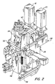
- a machining tool assembly embodying the present invention is generally designated by the numeral 10 and is mounted on the bridge 12 which is supported on side rails 14 (only one is shown) for movement over a workpiece support table or bed (not shown).
- the bridge 12 is moveable on the side rails 14 in the Y-axis direction by the motor 16.
- the machining tool assembly 10 is movable along the bridge 12 in the X-axis direction by motor 18.
- Two additional motors 20 and 22 effect movement of the machining tool (not shown) in the Y-axis and vertically in the Z-axis, as will be discussed more fully hereinafter.
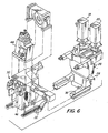
- the bridge 12 has a pair of guides 24 on which are seated the channel numbers 26 of the transverse axis housing 28 for movement of the housing 28 along the bridge 12 by operation of the motor 18.
- Mounted on the transverse axis housing 28 is the small axis housing generally designated by the number 30 which has racks 32 mounted thereon.
- the gear shaft 34 is driven by the motor 20 and has two pinions 36 engaged with the racks 32 to effect motion of the small axis housing 30 in the Y-axis direction. Motion of the housing 30 is guided by the linear slide assemblies 38.
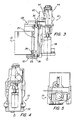
- a laser beam is transported to the cutting head along the bridge 12 by a beam delivery system including a bellows (not shown) in which it is shielded.
- the beam is directed by the bridge mirror 42 into a beam redirector generally designated by the 44 and which has a pair of mirrors (not shown) that initially direct the beam upwardly and then downwardly to a focussing lens (not shown) in the laser cutting head generally designated by the numeral 46.
- the bellows 47 shields the laser beam between the bridge mirror 42 on the transverse axis housing 28 and the laser cutting head 44 supported on the small axis housing 30.
- the laser cutting head 46 is movable vertically by the motor 22 to focus the laser beam on the workpiece.
- the computer control 60 is programmed to operate the drive motors to produce the desired motion of the laser cutting head 46 relative to the workpiece.
- the motor 16 moves the bridge 12 in the Y-axis direction
- the motor 18 moves the machining tool assembly in the X-axis direction.
- the motor 22 moves the cutting head 46 vertically (Z-axis) to focus the laser beam.
- the computer control 60 can also activate the drive motor 20 to move the small axis housing 30 in the Y-axis relative to the transverse axis housing 28.
- that motion may be effected by the relative movement of only the small axis housing 30, and that motion is faster due to the large inertia of the entire bridge 12.
- movement of the small axis housing 30 also tends to provide better quality cutting action for intricate contours. If a large displacement along the Y-axis is required to reposition the laser cutting head 46 relative to the workpiece, or if the length of the cut exceeds the range of motion of the small axis housing 30, the computer control 60 will activate the motor 16 to move the bridge 12. On occasion, both Y-axis drives may be operated simultaneously.
- FIG 8 therein illustrated is a workpiece 62 on which are laid out 23 cutout parts configurations which are identified by numerals 1-9 either individually or in groups as shown by dotted line.
- the arrows indicate the range of travel of the small axis housing, relative to the transverse axis housing 28.
- the cutouts of 1-5, 7 and 9 can be effected by using the Y-axis motion of only the small axis housing 30.
- the cutouts 6 and 8 exceed the length of travel of the small axis housing 30 and require use of the bridge drive motor 16 either for the entire motion in the Y-axis or to reposition the bridge 12 for further cutting by movement of the small axis housing 30.
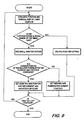
- a computer program to optimize the cutting action selects the appropriate Y-axis device action for the contours of the cuts to be made so as to maximize use of the motion provided by the small axis housing 30.
- the layout of the parts on the workpiece is done off-line using CAD software, and the layout program is then transferred to the machine tool computer.
- the entire machining tool assembly can be enclosed in a protective housing if so desired.
- the power supply cables for the several motors are generally supported on the bridge so that the machining tool assembly can move back and forth along the length of the bridge. The same is true with respect to tubing for supplying cutting or shielding gas to the laser cutting head.
- the bridge is typically a substantial structure requiring a relatively powerful motor to effect its motion along the length of the worktable.
- a small housing containing the laser cutting head can be relatively light and can be moved very quickly with relatively little inertia to be overcome.
- the laser cutting action afforded by movement of the small housing is more precise, particularly when there is change in direction.
- the computer control software can easily manage the cutting procedure and synchronize the motion in both X and Y-axes and the superposition of the two motions possible in the Z-axis in order to best process the workpiece.
- the range of motion of the small axis housing is 100 mm, but longer ranges may be readily provided.
- the software will normally evaluate all cuts within the numeric control program including absolute position, relative position to each other and overall size of each part.
- the overall size will determine which cuts will fit within the working range of the small axis motion; the relative position of the contours to each other will define how many consecutive parts can be cut with the small axis motion without moving the entire bridge, and the absolute position defines the base position for the bridge at the start of any given action.
- the machine control positions both axes during the movement to the next cut.
- the bridge will be placed so that the maximum possible numbers of cuts can be reached by the small axis motion without moving the bridge.
- the program determines that the contour of a part falls outside this envelope, the bridge moves to a new base position for the next series of cuts utilizing only the motion of the small axis housing.
- the software will optimize the process by minimizing the movements of the bridge and the cutting required by motion of the bridge and by concurrently maximizing the cutting which is accomplished by the motion of the small axis housing. If a contour is of a length which exceeds the working range of the motion for the small axis housing, there are several possibilities:
- the machine tool of the present invention is one which provides relatively rapid machining . action by minimizing the motion required of the large bridge on which the machining tool is supported. Moreover, since the machining tool can be moved very quickly in the one axis and relatively small mass is required to be moved, the cutting action can be more precise in the cutting of complex contours. The reduction in motion of the bridge also provides a longer-lived installation and reduces the cost of operation.
Abstract
Description
- The present invention relates to machine tools, and, more particularly, to machine tools in which the machining head is moved in multiple axes relative to the workpiece.
- In laser cutting installations and other machining operations involving large plate-like workpieces, it is common to support the workpiece on a worktable and to effect relative movement between the machining head and the workpiece. Although the worktable can be moved relative to the machining head, generally it is preferable to mount the machining tool on a support located above the workpiece and to move the support with the machining head thereon relative to the workpiece in both X and Y axes under computer control. Typically, the support for the machining head is a bridge which extends between the side rails and on which it is movable relative to the workpiece on one axis. Moreover, the machining head is generally supported on the bridge so that it is movable along the length of the bridge thus providing relative motion of the machining head in both X and Y directions.
- As will be readily appreciated, the bridge is a substantial structure with a relatively large mass so that motion of the bridge in the one axis requires substantial power to overcome the inertia and to effect the continued motion. The power for movement in the transverse direction is much less because the machining head is lighter and it moves along the length of the bridge.
- Because of the large mass and the need to start and stop the motion of the bridge, the cutting action of small intricate contours may not be as precise as is desirable, and the costs and wear of the drive system for the bridge can adversely effect the economics of the types of parts to be processed in a particular machine tool installation are small and of intricate configuration.
- Accordingly, it is an object of the present invention to provide a novel machine tool in which the motion required of a substantial bridge or like support may be substantially reduced.
- It is also an object to provide such a machine tool in which the quality of the machining of small intricate contours is improved.
- Another object is to provide such a machine tool which can be fabricated readily and which is relatively simple to operate.
- It has now been found that the foregoing and related objects may be readily attained a machine tool for machining workpieces by motion of the machining tool relative to the workpiece comprising a worktable having X and Y axes and adapted to support a workpiece thereon, and a support extending transversely above the worktable in the X-axis and movable along the Y-axis of the worktable. First machining tool mounting means is movably mounted on the support for movement along the support in the X-axis, and second machining tool mounting means is movably mounted on the first machining tool mounting means for movement in the Y-axis relative to the support within a range of motion. The machining tool mounted in the second machining tool mounting means.
- Also provided are first drive means for the support to move the support in the Y-axis over the worktable, second drive means for the first machining tool mounting means to move the first machining tool mounting means in the X-axis along the support, and third drive means for moving the second machining tool mounting means in the Y-axis relative to the first machining tool mounting means. A computer control is provided to effect operation of the first and second drive means to move the machining tool in X and Y axes to machine a workpiece supported on the worktable and to effect operation of the third drive means for rapid movement of the machining tool in the Y-axis.
- Generally, the support is a bridge member spaced above and extending transversely of the worktable, and the machining tool is supported on the second machining tool mounting means for vertical movement in a Z-axis. The machine tool includes fourth drive means for moving the machining tool in the Z-axis, and the computer control also effects operation of the fourth drive means.
- The computer control includes means for determining whether a desired length of movement in the Y-axis is within the range of motion of the second machining tool mounting means on the first machining tool mounting means so as to effect the desired movement by the third drive means in the Y-axis. Preferably, the computer control also includes means for determining whether a desired length of movement in the Y-axis is beyond the range of motion of the second machining tool mounting means and for effecting the desired movement of the machining tool in the Y-axis by operation of the first drive means to move the support and by operation of the third drive means to move the second machining tool mounting means. The computer control desirably may include means for effecting a large displacement of the support in the Y-axis to reposition the machining tool relative to the workpiece and thereafter for effecting a smaller displacement of the second machining tool mounting means in the Y-axis to effect the machining of the workpiece in the Y-axis.
- The machining tool may be a laser cutting head, and the machine tool is desirably mounted in a housing providing the second machining tool mounting means and slidable on guides supported on a transverse axis housing providing the first machining tool mounting means and which is movable on the support in the X-axis.
-
- Figure 1 is a fragmentary plan view of a laser cutting installation having a laser cutting assembly embodying the present invention mounted on the bridge;
- Figure 2 is a perspective view of the laser cutting assembly with the housing removed;
- Figure 3 is a side elevational view thereof as mounted on the bridge;
- Figure 4 is a front elevational view thereof;
- Figure 5 is a top view thereof;
- Figure 6 is a partially exploded view thereof showing the major subassemblies;
- Figure 7 is a diagrammatic view showing the several axes of motion;
- Figure 8 is an illustration of various parts laid out on a workpiece ad showing which can be cut by use of the small Y-axis motion; and
- Figure 9 is a flow chart of computer software which determines the Y-axis motions to be employed in machining parts from a workpiece.
-
- As seen in Figure 1, a machining tool assembly embodying the present invention is generally designated by the
numeral 10 and is mounted on thebridge 12 which is supported on side rails 14 (only one is shown) for movement over a workpiece support table or bed (not shown). Thebridge 12 is moveable on theside rails 14 in the Y-axis direction by themotor 16. Themachining tool assembly 10 is movable along thebridge 12 in the X-axis direction bymotor 18. Twoadditional motors - Turning next to Figures 2-6, the
bridge 12 has a pair ofguides 24 on which are seated thechannel numbers 26 of thetransverse axis housing 28 for movement of thehousing 28 along thebridge 12 by operation of themotor 18. Mounted on thetransverse axis housing 28 is the small axis housing generally designated by thenumber 30 which has racks 32 mounted thereon. Thegear shaft 34 is driven by themotor 20 and has twopinions 36 engaged with theracks 32 to effect motion of thesmall axis housing 30 in the Y-axis direction. Motion of thehousing 30 is guided by thelinear slide assemblies 38. - A laser beam is transported to the cutting head along the
bridge 12 by a beam delivery system including a bellows (not shown) in which it is shielded. The beam is directed by thebridge mirror 42 into a beam redirector generally designated by the 44 and which has a pair of mirrors (not shown) that initially direct the beam upwardly and then downwardly to a focussing lens (not shown) in the laser cutting head generally designated by thenumeral 46. Thebellows 47 shields the laser beam between thebridge mirror 42 on thetransverse axis housing 28 and thelaser cutting head 44 supported on thesmall axis housing 30. Thelaser cutting head 46 is movable vertically by themotor 22 to focus the laser beam on the workpiece. - In operation of the machine tool, the
computer control 60 is programmed to operate the drive motors to produce the desired motion of thelaser cutting head 46 relative to the workpiece. As in conventional, themotor 16 moves thebridge 12 in the Y-axis direction, and themotor 18 moves the machining tool assembly in the X-axis direction. Themotor 22 moves thecutting head 46 vertically (Z-axis) to focus the laser beam. - The
computer control 60 can also activate thedrive motor 20 to move thesmall axis housing 30 in the Y-axis relative to thetransverse axis housing 28. Thus, when only small Y-axis motion for the cutting action is required, that motion may be effected by the relative movement of only thesmall axis housing 30, and that motion is faster due to the large inertia of theentire bridge 12. Because there is less mass to be moved, movement of thesmall axis housing 30 also tends to provide better quality cutting action for intricate contours. If a large displacement along the Y-axis is required to reposition thelaser cutting head 46 relative to the workpiece, or if the length of the cut exceeds the range of motion of thesmall axis housing 30, thecomputer control 60 will activate themotor 16 to move thebridge 12. On occasion, both Y-axis drives may be operated simultaneously. - Turning now to Figure 8, therein illustrated is a
workpiece 62 on which are laid out 23 cutout parts configurations which are identified by numerals 1-9 either individually or in groups as shown by dotted line. The arrows indicate the range of travel of the small axis housing, relative to thetransverse axis housing 28. As can be seen, the cutouts of 1-5, 7 and 9 can be effected by using the Y-axis motion of only thesmall axis housing 30. Thecutouts 6 and 8 exceed the length of travel of thesmall axis housing 30 and require use of thebridge drive motor 16 either for the entire motion in the Y-axis or to reposition thebridge 12 for further cutting by movement of thesmall axis housing 30. - As seen in Figure 9, a computer program to optimize the cutting action selects the appropriate Y-axis device action for the contours of the cuts to be made so as to maximize use of the motion provided by the
small axis housing 30. Generally, the layout of the parts on the workpiece is done off-line using CAD software, and the layout program is then transferred to the machine tool computer. - As previously indicated, the entire machining tool assembly can be enclosed in a protective housing if so desired. The power supply cables for the several motors are generally supported on the bridge so that the machining tool assembly can move back and forth along the length of the bridge. The same is true with respect to tubing for supplying cutting or shielding gas to the laser cutting head.
- It will be readily appreciated that the addition of the second drive in the Y-axis affords significant advantages in time for operation, quality of cutting action and wear on the larger machine parts. The bridge is typically a substantial structure requiring a relatively powerful motor to effect its motion along the length of the worktable. In contrast, a small housing containing the laser cutting head can be relatively light and can be moved very quickly with relatively little inertia to be overcome. As a result, the laser cutting action afforded by movement of the small housing is more precise, particularly when there is change in direction. The computer control software can easily manage the cutting procedure and synchronize the motion in both X and Y-axes and the superposition of the two motions possible in the Z-axis in order to best process the workpiece.
- In a commercial embodiment of the present invention, the range of motion of the small axis housing is 100 mm, but longer ranges may be readily provided.
- The software will normally evaluate all cuts within the numeric control program including absolute position, relative position to each other and overall size of each part. The overall size will determine which cuts will fit within the working range of the small axis motion; the relative position of the contours to each other will define how many consecutive parts can be cut with the small axis motion without moving the entire bridge, and the absolute position defines the base position for the bridge at the start of any given action.
- With this information in hand, the machine control positions both axes during the movement to the next cut. The bridge will be placed so that the maximum possible numbers of cuts can be reached by the small axis motion without moving the bridge. When the program determines that the contour of a part falls outside this envelope, the bridge moves to a new base position for the next series of cuts utilizing only the motion of the small axis housing. Thus, the software will optimize the process by minimizing the movements of the bridge and the cutting required by motion of the bridge and by concurrently maximizing the cutting which is accomplished by the motion of the small axis housing. If a contour is of a length which exceeds the working range of the motion for the small axis housing, there are several possibilities:
- 1. The contour of the part can be cut completely by using the motion of the bridge.
- 2. The large contour can be split into several smaller segments which can be cut by use of the small axis motion with the bridge being periodically moved. Obviously another potential solution is to reorient the parts on the workpiece so that the length in the axis is within the range of motion of the small axis housing as indicated previously.
-
- Thus it can be seen from the foregoing detailed specification and attached drawings that the machine tool of the present invention is one which provides relatively rapid machining . action by minimizing the motion required of the large bridge on which the machining tool is supported. Moreover, since the machining tool can be moved very quickly in the one axis and relatively small mass is required to be moved, the cutting action can be more precise in the cutting of complex contours. The reduction in motion of the bridge also provides a longer-lived installation and reduces the cost of operation.
Claims (12)
- A machine tool for machining workpieces by motion of a machining tool relative to the workpiece comprising:(a) a worktable having X and Y axes and adapted to support a workpiece thereon;(b) a support extending transversely above said worktable in the X-axis and movable along the γ-axis of said worktable;(c) first machining tool mounting means movably mounted on said support for movement along said support in said X-axis;(d) second machining tool mounting means movably mounted on said first machining tool mounting means for movement in said Y-axis relative to said support within a range of;(e) a machining tool mounted said second machining tool mounting means;(f) first drive means for said support to move said support in said Y-axis over said worktable;(g) second drive means for said first machining tool mounting means to move said first machining tool mounting means in said X-axis along said support;(h) third drive means for moving said second machining tool mounting means in said Y-axis relative to said first machining tool mounting means; and(i) a computer control for effecting operation of said first and second drive means to move said machining tool in X and Y axes and for effecting operation of said third drive means for rapid movement of said machining tool in the Y-axis to machine a workpiece supported on said worktable.
- The machine tool in accordance with Claim 1 wherein said support is a bridge member spaced above and extending transversely of said worktable.
- The machine tool in accordance with Claim 1 wherein said machining tool is supported on said second machining tool mounting means for vertical movement in a Z-axis and said machine tool includes fourth drive means for moving said machining tool in said Z-axis, said computer control also effecting operation of said fourth drive means.
- The machine tool in accordance with Claim 1 wherein said computer control includes means for determining whether a desired length of movement in the Y-axis is within said range of motion of said second machining tool mounting means on said first machining tool mounting means in said Y-axis to effect the desired movement by said third drive means.
- The machine tool in accordance with Claim 1 wherein said computer control includes means for determining whether a desired length of movement in the Y-axis is beyond said range of motion of said second machining tool mounting means and for effecting the desired movement of the machining tool in the Y-axis by operation of said first drive means to move said support and by operation of said third drive means to move said second machining tool mounting means.
- The machine tool in accordance with Claim 1 wherein said computer control includes means for effecting a large displacement of said support in the Y-axis to reposition said machining tool relative to the workpiece and, thereafter for effecting a smaller displacement of said second machining tool mounting means in said Y-axis to effect machining on the workpiece in the Y-axis.
- The machine tool in accordance with Claim 1 wherein said machining tool is a laser cutting head.
- The machine tool in accordance with Claim 1 wherein said machining tool is mounted in a housing providing said second machining tool mounting means and slidable on guides supported on a transverse axis housing providing said first machining tool mounting means movable on said support in the Y-axis.
- A laser cutting machine tool for laser cutting of workpieces by motion of a laser cutting head relative to the workpiece comprising:(a) a worktable having X and Y axes and adapted to support a workpiece thereon;(b) a bridge member extending transversely above said worktable in the X-axis and movable along the Y-axis of said worktable;(c) first tool mounting means movably mounted on said bridge member for movement along said support in said X-axis;(d) second tool mounting means movably mounted on said first machining tool mounting means for movement in said Y-axis relative to said support within a range of;(e) a laser cutting head mounted said second tool mounting means;(f) first drive means for said bridge member to move said bridge member in said Y-axis over said worktable;(g) second drive means for said first tool mounting means to move said first machining tool mounting means in said X-axis along said bridge member;(h) third drive means for moving said second tool mounting means in said Y-axis relative to said first machining tool mounting means; and(i) a computer control for effecting operation of said first and second drive means to move said laser cutting head tool in X and Y axes and for effecting operation of said third drive means for rapid movement of said cutting head in the Y-axis. Said computer control including means for determining whether a desired length of movement in the Y-axis is within said range of motion of said second machining tool mounting means on said first machining tool mounting means in said Y-axis to effect the desired movement by said third drive means and also including means for determining whether a desired length of movement in the Y-axis is beyond said range of motion of said second tool mounting means and for effecting the desired movement of the laser cutting head in the Y-axis by operation of said first drive means to move said bridge and by operation of said third drive means to move said second mounting means.
- The laser cutting machine tool in accordance with Claim 9, wherein said computer control includes means for effecting a large displacement of said bridge member in the Y-axis to reposition said machining tool relative to the workpiece and, thereafter for effecting a smaller displacement of said second machining tool mounting means in said Y-axis to effect machining on the workpiece in the Y-axis.
- The laser cutting machine tool in accordance with Claim 9, wherein said laser cutting head is supported on said second machining tool mounting means for vertical movement in a Z-axis and said machine tool includes fourth drive means for moving said machining tool in said Z-axis, said computer control also effecting operation of said fourth drive means.
- The laser cutting machine tool in accordance with Claim 9, wherein said machining tool is mounted in a housing providing said second machining tool mounting means and slidable on guides supported on a transverse axis housing providing said first tool mounting means movable on said support in the Y-axis.
Applications Claiming Priority (2)
| Application Number | Priority Date | Filing Date | Title |
|---|---|---|---|
| US10/156,886 US6835912B2 (en) | 2002-05-28 | 2002-05-28 | Laser cutting machine with two Y-axis drives |
| US156886 | 2002-05-28 |
Publications (2)
| Publication Number | Publication Date |
|---|---|
| EP1366846A1 true EP1366846A1 (en) | 2003-12-03 |
| EP1366846B1 EP1366846B1 (en) | 2007-02-21 |
Family
ID=29419634
Family Applications (1)
| Application Number | Title | Priority Date | Filing Date |
|---|---|---|---|
| EP03012011A Expired - Lifetime EP1366846B1 (en) | 2002-05-28 | 2003-05-28 | Laser cutting machine with two y-axis drives |
Country Status (4)
| Country | Link |
|---|---|
| US (2) | US6835912B2 (en) |
| EP (1) | EP1366846B1 (en) |
| AT (1) | ATE354450T1 (en) |
| DE (1) | DE60311916T2 (en) |
Cited By (8)
| Publication number | Priority date | Publication date | Assignee | Title |
|---|---|---|---|---|
| EP1688807A1 (en) * | 2005-02-04 | 2006-08-09 | Trumpf Werkzeugmaschinen GmbH + Co. KG | Method to divide the relative movement between a workpiece and a tool of a machine tool |
| WO2009121335A1 (en) * | 2008-03-31 | 2009-10-08 | Trumpf Werkzeugmaschinen Gmbh + Co. Kg | Method for optimizing the occupancy of a pipe or several pipes with several pipe parts to be cut for a machining installation |
| EP2283963A1 (en) | 2009-07-27 | 2011-02-16 | SALVAGNINI ITALIA S.p.A. | Manipulator of low inertia for laser cutting machines for flat sheet metals |
| CN102156436A (en) * | 2011-05-18 | 2011-08-17 | 山西飞虹激光科技有限公司 | Multi-closed-loop feedback control system for laser cutter |
| US8260443B2 (en) | 2007-06-22 | 2012-09-04 | Trumpf Werkzeugmaschinen Gmbh + Co. Kg | Method for the optimized movement co-ordination of measuring machines or machine tools with redundant axles having a translatory action |
| CN103100812A (en) * | 2013-03-06 | 2013-05-15 | 海宁市钱江勘察机械有限公司 | Dual-gun welding machine |
| CN103801830A (en) * | 2014-03-05 | 2014-05-21 | 济南邦德数控设备有限公司 | Portable intermediate transmission way laser cutting bed cutter |
| EP4041489A4 (en) * | 2020-10-27 | 2023-06-21 | Baykal Makina Sanayi Ve Ticaret Anonim Sirketi | Bridge and body embodiment for laser cutting machine |
Families Citing this family (13)
| Publication number | Priority date | Publication date | Assignee | Title |
|---|---|---|---|---|
| US20050103764A1 (en) * | 2003-10-01 | 2005-05-19 | Trumpf, Inc. | Laser cutting machine with two X-axis drives |
| DE102007017899B4 (en) * | 2007-04-13 | 2017-02-16 | Innotech Ingenieursgesellschaft Mbh | Apparatus and method for cutting food material |
| US8458871B2 (en) * | 2008-06-26 | 2013-06-11 | Hg-Farley Laserlab Co. Pty Ltd | Secondary positioning device for workpiece machining |
| WO2012050191A1 (en) * | 2010-10-15 | 2012-04-19 | 三菱電機株式会社 | Laser processing machine and bellows device |
| JP5132838B2 (en) * | 2010-11-29 | 2013-01-30 | 三菱電機株式会社 | Optical path structure of laser processing machine |
| US20160059363A1 (en) * | 2014-06-25 | 2016-03-03 | Pittsburgh Portable Laser Company, Llc | Portable computer numerically controlled cutting machine with folding arm |
| EP3023190A1 (en) | 2014-11-24 | 2016-05-25 | Bystronic Laser AG | Cutting head device |
| CN104759753B (en) * | 2015-03-30 | 2016-08-31 | 江苏大学 | The co-ordination of multisystem automatization improves the method for induced with laser cavitation reinforcement |
| KR102540188B1 (en) | 2015-06-22 | 2023-06-07 | 일렉트로 싸이언티픽 인더스트리이즈 인코포레이티드 | Multi-axis machine tools and how to control them |
| CN108555439B (en) * | 2017-08-21 | 2019-10-18 | 泉州味盛食品有限公司 | A kind of efficient bridge construction device |
| US10744595B2 (en) | 2018-05-09 | 2020-08-18 | Trumpf Inc. | Transversal laser cutting machine |
| WO2020060981A1 (en) | 2018-09-19 | 2020-03-26 | Rendyr | Portable laser cutter |
| DE102018131781A1 (en) * | 2018-12-11 | 2020-06-18 | Trumpf Werkzeugmaschinen Gmbh + Co. Kg | Pipe processing machine for cutting pipes or profiles using a laser beam |
Citations (8)
| Publication number | Priority date | Publication date | Assignee | Title |
|---|---|---|---|---|
| US3258776A (en) * | 1963-01-09 | 1966-06-28 | Dobbie Mcinnes Electronics Ltd | Graph plotting mechanism |
| EP0021972A1 (en) * | 1979-06-15 | 1981-01-07 | SORMEL Société anonyme dite: | Precise manipulator at high cadence |
| DE3400017A1 (en) * | 1984-01-02 | 1985-08-08 | Held GmbH, 6056 Heusenstamm | Multiaxial material machining station |
| DE3502631A1 (en) * | 1984-04-13 | 1985-10-24 | VEB Kombinat Schiffbau, DDR 2500 Rostock | Welding robot for welding horizontal fillet seams in polygonal compartment constructions |
| US5637243A (en) * | 1993-09-27 | 1997-06-10 | Mitsubishi Denki Kabushiki Kaisha | Laser cutting machine |
| US5660748A (en) * | 1995-02-28 | 1997-08-26 | Mitsubishi Denki Kabushiki Kaisha | Laser beam machine with an optical fiber cable |
| US5910260A (en) * | 1995-04-19 | 1999-06-08 | Gerber Garment Technology, Inc. | Laser cutter and method for cutting sheet material |
| EP0927596A2 (en) * | 1997-12-31 | 1999-07-07 | PRIMA INDUSTRIE S.p.A. | An operative head for a laser machine |
Family Cites Families (17)
| Publication number | Priority date | Publication date | Assignee | Title |
|---|---|---|---|---|
| US571585A (en) * | 1896-11-17 | Office-indicator | ||
| US2717979A (en) | 1951-09-18 | 1955-09-13 | Boeing Co | Pattern controlled coarse-fine servomechanism |
| US3209121A (en) | 1962-09-04 | 1965-09-28 | Union Carbide Corp | Electrode proximity control |
| CH436751A (en) | 1966-05-31 | 1967-05-31 | Contraves Ag | Coordinatograph |
| US3886421A (en) * | 1973-09-10 | 1975-05-27 | Ibm | Precision tool and workpiece positioning apparatus with ringout detection |
| DE2847943C2 (en) | 1978-11-04 | 1980-07-10 | A. Ehrenreich Gmbh & Co Kg, 4000 Duesseldorf | CNC-controlled single-spindle precision lathe with a concave or convex tool path |
| US4561814A (en) * | 1981-07-09 | 1985-12-31 | Dahlgren Jr William V | Mechanical tool manipulating method and apparatus |
| DE3410913A1 (en) * | 1984-03-24 | 1985-10-03 | Trumpf GmbH & Co, 7257 Ditzingen | MACHINE TOOL FOR MECHANICAL AND LASER BEAM PROCESSING OF A WORKPIECE |
| US4659902A (en) * | 1985-04-22 | 1987-04-21 | Westinghouse Electric Corp. | Robot laser system |
| US5267478A (en) | 1988-07-08 | 1993-12-07 | Mytronic Ab | Device for a rapid positioning of a heavy carriage |
| DE4123323C2 (en) | 1991-07-13 | 1994-02-10 | Andreas Ehlerding | Tool carrier |
| JP3126216B2 (en) * | 1992-05-29 | 2001-01-22 | 株式会社アマダ | Laser processing machine |
| US5329457A (en) * | 1993-04-15 | 1994-07-12 | General Electric Company | Comprehensive three-dimensional rotary tool point compensation |
| JP2921727B2 (en) * | 1994-01-27 | 1999-07-19 | 株式会社アマダ | Laser processing equipment |
| US5751585A (en) | 1995-03-20 | 1998-05-12 | Electro Scientific Industries, Inc. | High speed, high accuracy multi-stage tool positioning system |
| US6392192B1 (en) * | 1999-09-15 | 2002-05-21 | W. A. Whitney Co. | Real time control of laser beam characteristics in a laser-equipped machine tool |
| US6706999B1 (en) * | 2003-02-24 | 2004-03-16 | Electro Scientific Industries, Inc. | Laser beam tertiary positioner apparatus and method |
-
2002
- 2002-05-28 US US10/156,886 patent/US6835912B2/en not_active Expired - Fee Related
-
2003
- 2003-05-28 DE DE60311916T patent/DE60311916T2/en not_active Expired - Lifetime
- 2003-05-28 EP EP03012011A patent/EP1366846B1/en not_active Expired - Lifetime
- 2003-05-28 AT AT03012011T patent/ATE354450T1/en active
-
2004
- 2004-01-12 US US10/755,738 patent/US6825439B2/en not_active Expired - Fee Related
Patent Citations (8)
| Publication number | Priority date | Publication date | Assignee | Title |
|---|---|---|---|---|
| US3258776A (en) * | 1963-01-09 | 1966-06-28 | Dobbie Mcinnes Electronics Ltd | Graph plotting mechanism |
| EP0021972A1 (en) * | 1979-06-15 | 1981-01-07 | SORMEL Société anonyme dite: | Precise manipulator at high cadence |
| DE3400017A1 (en) * | 1984-01-02 | 1985-08-08 | Held GmbH, 6056 Heusenstamm | Multiaxial material machining station |
| DE3502631A1 (en) * | 1984-04-13 | 1985-10-24 | VEB Kombinat Schiffbau, DDR 2500 Rostock | Welding robot for welding horizontal fillet seams in polygonal compartment constructions |
| US5637243A (en) * | 1993-09-27 | 1997-06-10 | Mitsubishi Denki Kabushiki Kaisha | Laser cutting machine |
| US5660748A (en) * | 1995-02-28 | 1997-08-26 | Mitsubishi Denki Kabushiki Kaisha | Laser beam machine with an optical fiber cable |
| US5910260A (en) * | 1995-04-19 | 1999-06-08 | Gerber Garment Technology, Inc. | Laser cutter and method for cutting sheet material |
| EP0927596A2 (en) * | 1997-12-31 | 1999-07-07 | PRIMA INDUSTRIE S.p.A. | An operative head for a laser machine |
Cited By (13)
| Publication number | Priority date | Publication date | Assignee | Title |
|---|---|---|---|---|
| US7482776B2 (en) | 2005-02-04 | 2009-01-27 | Trumpf Werkzeugmaschinen Gmbh + Co. Kg | Controlling relative movement between a workpiece and a tool of a machine tool |
| EP1688807A1 (en) * | 2005-02-04 | 2006-08-09 | Trumpf Werkzeugmaschinen GmbH + Co. KG | Method to divide the relative movement between a workpiece and a tool of a machine tool |
| US8260443B2 (en) | 2007-06-22 | 2012-09-04 | Trumpf Werkzeugmaschinen Gmbh + Co. Kg | Method for the optimized movement co-ordination of measuring machines or machine tools with redundant axles having a translatory action |
| CN102137734B (en) * | 2008-03-31 | 2014-09-17 | 通快机床两合公司 | Method for optimizing the occupancy of a pipe or several pipes with several pipe parts to be cut for a machining installation |
| WO2009121335A1 (en) * | 2008-03-31 | 2009-10-08 | Trumpf Werkzeugmaschinen Gmbh + Co. Kg | Method for optimizing the occupancy of a pipe or several pipes with several pipe parts to be cut for a machining installation |
| US9199336B2 (en) | 2008-03-31 | 2015-12-01 | Trumpf Werkzeugmaschinen Gmbh + Co. Kg | Method for allocation of one or more pipes with several pipe parts to be cut |
| EP2283963A1 (en) | 2009-07-27 | 2011-02-16 | SALVAGNINI ITALIA S.p.A. | Manipulator of low inertia for laser cutting machines for flat sheet metals |
| US8440932B2 (en) | 2009-07-27 | 2013-05-14 | Salvagnini Italia S.P.A. | Manipulator at low inertia for laser cutting machines for flat sheet metals |
| CN102156436A (en) * | 2011-05-18 | 2011-08-17 | 山西飞虹激光科技有限公司 | Multi-closed-loop feedback control system for laser cutter |
| CN103100812A (en) * | 2013-03-06 | 2013-05-15 | 海宁市钱江勘察机械有限公司 | Dual-gun welding machine |
| CN103100812B (en) * | 2013-03-06 | 2016-04-20 | 海宁市钱江勘察机械有限公司 | A kind of rush-harvesting and rush-planting welding machine |
| CN103801830A (en) * | 2014-03-05 | 2014-05-21 | 济南邦德数控设备有限公司 | Portable intermediate transmission way laser cutting bed cutter |
| EP4041489A4 (en) * | 2020-10-27 | 2023-06-21 | Baykal Makina Sanayi Ve Ticaret Anonim Sirketi | Bridge and body embodiment for laser cutting machine |
Also Published As
| Publication number | Publication date |
|---|---|
| DE60311916T2 (en) | 2007-10-31 |
| EP1366846B1 (en) | 2007-02-21 |
| US6825439B2 (en) | 2004-11-30 |
| US20030222065A1 (en) | 2003-12-04 |
| DE60311916D1 (en) | 2007-04-05 |
| US20040178181A1 (en) | 2004-09-16 |
| ATE354450T1 (en) | 2007-03-15 |
| US6835912B2 (en) | 2004-12-28 |
Similar Documents
| Publication | Publication Date | Title |
|---|---|---|
| US6835912B2 (en) | Laser cutting machine with two Y-axis drives | |
| EP2745959B1 (en) | Machine tool with lathe tool and scraping cutter | |
| EP2745958B1 (en) | Machine tool with lathe tool and milling cutter | |
| KR100652258B1 (en) | Automatic lathe | |
| US5525776A (en) | Compound machine tool | |
| EP2745968B1 (en) | Milling method for machining metallic member | |
| JP2008526521A (en) | Laser processing machine | |
| TWI505886B (en) | Method for making metallic member | |
| EP2687307B1 (en) | Method for machining curved surface using lathe | |
| TWI477334B (en) | Lathe | |
| CN114101898A (en) | Laser processing device | |
| US9718153B2 (en) | Method for machining metallic member using lathing and scraping | |
| EP0539633B1 (en) | Gantry-type machine tool | |
| EP3556509B1 (en) | Combined processing machine with a laser beam splitter | |
| US20050103764A1 (en) | Laser cutting machine with two X-axis drives | |
| JP4382426B2 (en) | lathe | |
| US9757824B2 (en) | Method for machining metallic member using lathing and scraping | |
| EP2745960B1 (en) | Method for machining metallic member using lathing and milling | |
| JP3126216B2 (en) | Laser processing machine | |
| JP2005153036A (en) | Laser cutting machine including two y-axis drivers | |
| KR100738390B1 (en) | Ultra narrow vertical machining center with column inside auto tool changer | |
| EP2745962B1 (en) | Method for machining metallic member using lathing and scraping | |
| CN113399767A (en) | Linear cutting machine | |
| KR19990030523A (en) | 2-DOF actuator for mold polishing | |
| JPS63248590A (en) | Laser beam machine |
Legal Events
| Date | Code | Title | Description |
|---|---|---|---|
| PUAI | Public reference made under article 153(3) epc to a published international application that has entered the european phase |
Free format text: ORIGINAL CODE: 0009012 |
|
| AK | Designated contracting states |
Kind code of ref document: A1 Designated state(s): AT BE BG CH CY CZ DE DK EE ES FI FR GB GR HU IE IT LI LU MC NL PT RO SE SI SK TR |
|
| AX | Request for extension of the european patent |
Extension state: AL LT LV MK |
|
| 17P | Request for examination filed |
Effective date: 20040514 |
|
| AKX | Designation fees paid |
Designated state(s): AT BE BG CH CY CZ DE DK EE ES FI FR GB GR HU IE IT LI LU MC NL PT RO SE SI SK TR |
|
| 17Q | First examination report despatched |
Effective date: 20050317 |
|
| GRAP | Despatch of communication of intention to grant a patent |
Free format text: ORIGINAL CODE: EPIDOSNIGR1 |
|
| GRAS | Grant fee paid |
Free format text: ORIGINAL CODE: EPIDOSNIGR3 |
|
| GRAA | (expected) grant |
Free format text: ORIGINAL CODE: 0009210 |
|
| AK | Designated contracting states |
Kind code of ref document: B1 Designated state(s): AT BE BG CH CY CZ DE DK EE ES FI FR GB GR HU IE IT LI LU MC NL PT RO SE SI SK TR |
|
| PG25 | Lapsed in a contracting state [announced via postgrant information from national office to epo] |
Ref country code: DK Free format text: LAPSE BECAUSE OF FAILURE TO SUBMIT A TRANSLATION OF THE DESCRIPTION OR TO PAY THE FEE WITHIN THE PRESCRIBED TIME-LIMIT Effective date: 20070221 Ref country code: NL Free format text: LAPSE BECAUSE OF FAILURE TO SUBMIT A TRANSLATION OF THE DESCRIPTION OR TO PAY THE FEE WITHIN THE PRESCRIBED TIME-LIMIT Effective date: 20070221 Ref country code: SI Free format text: LAPSE BECAUSE OF FAILURE TO SUBMIT A TRANSLATION OF THE DESCRIPTION OR TO PAY THE FEE WITHIN THE PRESCRIBED TIME-LIMIT Effective date: 20070221 Ref country code: FI Free format text: LAPSE BECAUSE OF FAILURE TO SUBMIT A TRANSLATION OF THE DESCRIPTION OR TO PAY THE FEE WITHIN THE PRESCRIBED TIME-LIMIT Effective date: 20070221 Ref country code: BE Free format text: LAPSE BECAUSE OF FAILURE TO SUBMIT A TRANSLATION OF THE DESCRIPTION OR TO PAY THE FEE WITHIN THE PRESCRIBED TIME-LIMIT Effective date: 20070221 |
|
| REG | Reference to a national code |
Ref country code: GB Ref legal event code: FG4D |
|
| REG | Reference to a national code |
Ref country code: CH Ref legal event code: EP |
|
| REG | Reference to a national code |
Ref country code: CH Ref legal event code: NV Representative=s name: BOVARD AG PATENTANWAELTE |
|
| REF | Corresponds to: |
Ref document number: 60311916 Country of ref document: DE Date of ref document: 20070405 Kind code of ref document: P |
|
| REG | Reference to a national code |
Ref country code: IE Ref legal event code: FG4D |
|
| PG25 | Lapsed in a contracting state [announced via postgrant information from national office to epo] |
Ref country code: SE Free format text: LAPSE BECAUSE OF FAILURE TO SUBMIT A TRANSLATION OF THE DESCRIPTION OR TO PAY THE FEE WITHIN THE PRESCRIBED TIME-LIMIT Effective date: 20070521 |
|
| PG25 | Lapsed in a contracting state [announced via postgrant information from national office to epo] |
Ref country code: BG Free format text: LAPSE BECAUSE OF EXPIRATION OF PROTECTION Effective date: 20070522 |
|
| PG25 | Lapsed in a contracting state [announced via postgrant information from national office to epo] |
Ref country code: ES Free format text: LAPSE BECAUSE OF FAILURE TO SUBMIT A TRANSLATION OF THE DESCRIPTION OR TO PAY THE FEE WITHIN THE PRESCRIBED TIME-LIMIT Effective date: 20070601 |
|
| PG25 | Lapsed in a contracting state [announced via postgrant information from national office to epo] |
Ref country code: PT Free format text: LAPSE BECAUSE OF FAILURE TO SUBMIT A TRANSLATION OF THE DESCRIPTION OR TO PAY THE FEE WITHIN THE PRESCRIBED TIME-LIMIT Effective date: 20070723 |
|
| NLV1 | Nl: lapsed or annulled due to failure to fulfill the requirements of art. 29p and 29m of the patents act | ||
| PG25 | Lapsed in a contracting state [announced via postgrant information from national office to epo] |
Ref country code: SK Free format text: LAPSE BECAUSE OF FAILURE TO SUBMIT A TRANSLATION OF THE DESCRIPTION OR TO PAY THE FEE WITHIN THE PRESCRIBED TIME-LIMIT Effective date: 20070221 |
|
| PLBE | No opposition filed within time limit |
Free format text: ORIGINAL CODE: 0009261 |
|
| STAA | Information on the status of an ep patent application or granted ep patent |
Free format text: STATUS: NO OPPOSITION FILED WITHIN TIME LIMIT |
|
| PG25 | Lapsed in a contracting state [announced via postgrant information from national office to epo] |
Ref country code: RO Free format text: LAPSE BECAUSE OF FAILURE TO SUBMIT A TRANSLATION OF THE DESCRIPTION OR TO PAY THE FEE WITHIN THE PRESCRIBED TIME-LIMIT Effective date: 20070221 Ref country code: CZ Free format text: LAPSE BECAUSE OF FAILURE TO SUBMIT A TRANSLATION OF THE DESCRIPTION OR TO PAY THE FEE WITHIN THE PRESCRIBED TIME-LIMIT Effective date: 20070221 |
|
| 26N | No opposition filed |
Effective date: 20071122 |
|
| PG25 | Lapsed in a contracting state [announced via postgrant information from national office to epo] |
Ref country code: MC Free format text: LAPSE BECAUSE OF NON-PAYMENT OF DUE FEES Effective date: 20070531 |
|
| PG25 | Lapsed in a contracting state [announced via postgrant information from national office to epo] |
Ref country code: GR Free format text: LAPSE BECAUSE OF FAILURE TO SUBMIT A TRANSLATION OF THE DESCRIPTION OR TO PAY THE FEE WITHIN THE PRESCRIBED TIME-LIMIT Effective date: 20070522 |
|
| PG25 | Lapsed in a contracting state [announced via postgrant information from national office to epo] |
Ref country code: IE Free format text: LAPSE BECAUSE OF NON-PAYMENT OF DUE FEES Effective date: 20070528 |
|
| PG25 | Lapsed in a contracting state [announced via postgrant information from national office to epo] |
Ref country code: EE Free format text: LAPSE BECAUSE OF FAILURE TO SUBMIT A TRANSLATION OF THE DESCRIPTION OR TO PAY THE FEE WITHIN THE PRESCRIBED TIME-LIMIT Effective date: 20070221 |
|
| PG25 | Lapsed in a contracting state [announced via postgrant information from national office to epo] |
Ref country code: CY Free format text: LAPSE BECAUSE OF FAILURE TO SUBMIT A TRANSLATION OF THE DESCRIPTION OR TO PAY THE FEE WITHIN THE PRESCRIBED TIME-LIMIT Effective date: 20070221 |
|
| PG25 | Lapsed in a contracting state [announced via postgrant information from national office to epo] |
Ref country code: LU Free format text: LAPSE BECAUSE OF NON-PAYMENT OF DUE FEES Effective date: 20070528 |
|
| PG25 | Lapsed in a contracting state [announced via postgrant information from national office to epo] |
Ref country code: HU Free format text: LAPSE BECAUSE OF FAILURE TO SUBMIT A TRANSLATION OF THE DESCRIPTION OR TO PAY THE FEE WITHIN THE PRESCRIBED TIME-LIMIT Effective date: 20070822 Ref country code: TR Free format text: LAPSE BECAUSE OF FAILURE TO SUBMIT A TRANSLATION OF THE DESCRIPTION OR TO PAY THE FEE WITHIN THE PRESCRIBED TIME-LIMIT Effective date: 20070221 |
|
| REG | Reference to a national code |
Ref country code: CH Ref legal event code: PFA Owner name: TRUMPF, INC. Free format text: TRUMPF, INC.#HYDE ROAD#FARMINGTON CONNECTICUT 06034 (US) -TRANSFER TO- TRUMPF, INC.#HYDE ROAD#FARMINGTON CONNECTICUT 06034 (US) |
|
| REG | Reference to a national code |
Ref country code: FR Ref legal event code: PLFP Year of fee payment: 14 |
|
| REG | Reference to a national code |
Ref country code: FR Ref legal event code: PLFP Year of fee payment: 15 |
|
| REG | Reference to a national code |
Ref country code: FR Ref legal event code: PLFP Year of fee payment: 16 |
|
| PGFP | Annual fee paid to national office [announced via postgrant information from national office to epo] |
Ref country code: FR Payment date: 20200522 Year of fee payment: 18 Ref country code: CH Payment date: 20200520 Year of fee payment: 18 |
|
| PGFP | Annual fee paid to national office [announced via postgrant information from national office to epo] |
Ref country code: GB Payment date: 20200527 Year of fee payment: 18 |
|
| PGFP | Annual fee paid to national office [announced via postgrant information from national office to epo] |
Ref country code: AT Payment date: 20200522 Year of fee payment: 18 |
|
| REG | Reference to a national code |
Ref country code: CH Ref legal event code: PL |
|
| REG | Reference to a national code |
Ref country code: AT Ref legal event code: MM01 Ref document number: 354450 Country of ref document: AT Kind code of ref document: T Effective date: 20210528 |
|
| GBPC | Gb: european patent ceased through non-payment of renewal fee |
Effective date: 20210528 |
|
| PG25 | Lapsed in a contracting state [announced via postgrant information from national office to epo] |
Ref country code: CH Free format text: LAPSE BECAUSE OF NON-PAYMENT OF DUE FEES Effective date: 20210531 Ref country code: AT Free format text: LAPSE BECAUSE OF NON-PAYMENT OF DUE FEES Effective date: 20210528 Ref country code: LI Free format text: LAPSE BECAUSE OF NON-PAYMENT OF DUE FEES Effective date: 20210531 |
|
| PG25 | Lapsed in a contracting state [announced via postgrant information from national office to epo] |
Ref country code: GB Free format text: LAPSE BECAUSE OF NON-PAYMENT OF DUE FEES Effective date: 20210528 |
|
| PG25 | Lapsed in a contracting state [announced via postgrant information from national office to epo] |
Ref country code: FR Free format text: LAPSE BECAUSE OF NON-PAYMENT OF DUE FEES Effective date: 20210531 |
|
| PGFP | Annual fee paid to national office [announced via postgrant information from national office to epo] |
Ref country code: IT Payment date: 20220524 Year of fee payment: 20 Ref country code: DE Payment date: 20220519 Year of fee payment: 20 |
|
| REG | Reference to a national code |
Ref country code: DE Ref legal event code: R071 Ref document number: 60311916 Country of ref document: DE |