EP1235217A1 - Apparatus and method for retaining different sizes of data cartridges in a storage magazine - Google Patents
Apparatus and method for retaining different sizes of data cartridges in a storage magazine Download PDFInfo
- Publication number
- EP1235217A1 EP1235217A1 EP01121586A EP01121586A EP1235217A1 EP 1235217 A1 EP1235217 A1 EP 1235217A1 EP 01121586 A EP01121586 A EP 01121586A EP 01121586 A EP01121586 A EP 01121586A EP 1235217 A1 EP1235217 A1 EP 1235217A1
- Authority
- EP
- European Patent Office
- Prior art keywords
- cartridge
- data
- chamber
- data cartridge
- storage magazine
- Prior art date
- Legal status (The legal status is an assumption and is not a legal conclusion. Google has not performed a legal analysis and makes no representation as to the accuracy of the status listed.)
- Withdrawn
Links
- 238000000034 method Methods 0.000 title claims abstract description 12
- 230000000717 retained effect Effects 0.000 description 7
- 238000005192 partition Methods 0.000 description 4
- 230000032258 transport Effects 0.000 description 3
- 238000003780 insertion Methods 0.000 description 2
- 230000037431 insertion Effects 0.000 description 2
- 239000000463 material Substances 0.000 description 2
- 238000010073 coating (rubber) Methods 0.000 description 1
- 239000006260 foam Substances 0.000 description 1
- 239000003292 glue Substances 0.000 description 1
- 238000004519 manufacturing process Methods 0.000 description 1
- 239000002184 metal Substances 0.000 description 1
- 239000012858 resilient material Substances 0.000 description 1
- 239000007787 solid Substances 0.000 description 1
- 229910001220 stainless steel Inorganic materials 0.000 description 1
- 239000010935 stainless steel Substances 0.000 description 1
Images


Classifications
-
- G—PHYSICS
- G11—INFORMATION STORAGE
- G11B—INFORMATION STORAGE BASED ON RELATIVE MOVEMENT BETWEEN RECORD CARRIER AND TRANSDUCER
- G11B17/00—Guiding record carriers not specifically of filamentary or web form, or of supports therefor
- G11B17/22—Guiding record carriers not specifically of filamentary or web form, or of supports therefor from random access magazine of disc records
-
- G—PHYSICS
- G11—INFORMATION STORAGE
- G11B—INFORMATION STORAGE BASED ON RELATIVE MOVEMENT BETWEEN RECORD CARRIER AND TRANSDUCER
- G11B15/00—Driving, starting or stopping record carriers of filamentary or web form; Driving both such record carriers and heads; Guiding such record carriers or containers therefor; Control thereof; Control of operating function
- G11B15/675—Guiding containers, e.g. loading, ejecting cassettes
- G11B15/68—Automatic cassette changing arrangements; automatic tape changing arrangements
Definitions
- the invention generally pertains to media storage systems for handling and storing data cartridges, and more specifically, to an apparatus and method for retaining at least two different sizes of data cartridges in a storage magazine of the media storage system.
- Autochangers or media storage systems are commonly used to store data cartridges and to retrieve desired data cartridges so that computer readable data may be written to and/or read from the data cartridges.
- large volumes of computer readable data can be stored on numerous data cartridges and accessed by a single computer or by multiple computers connected to the media storage system over a network.
- Such media storage systems are often referred to as "juke box” storage systems, and may include a storage magazine and a cartridge read/write device.
- the storage magazine serves as a storage location for the data cartridges.
- Multiple storage magazines are commonly arranged so that they form one or more vertical stacks.
- the media storage system also includes a cartridge engaging assembly or "picker" for moving among and accessing the data cartridges stored therein.
- the cartridge engaging assembly delivers the data cartridge to a storage magazine in the media storage system.
- the cartridge engaging assembly delivers the data cartridge to the read/write device, and may also return the data cartridge to the storage magazine after it has been accessed.
- Media storage systems are typically designed for use with data cartridges of a particular type (i.e., configuration or size).
- a data cartridge is the so-called digital linear tape (DLT) data cartridge.
- DLT digital linear tape
- LTO linear tape open
- the LTO data cartridge is approximately three millimeters narrower than the DLT data cartridge. Accordingly, a media storage system designed for use with an LTO data cartridge typically cannot accommodate the wider DLT data cartridges. Of course, this situation is disadvantageous in that it limits the media storage system to use with a single type of data cartridge.
- one type of storage magazine may be configured to receive the DLT type of data cartridges while another type of storage magazine may be configured to receive another data cartridge type (e.g., an LTO data cartridge).
- the media storage system can then be reconfigured to receive a different data cartridge type by replacing the storage magazines with the appropriate type.
- the storage magazine itself may be retrofitted with insertable fins or rib members.
- the storage magazine configured to receive the larger DLT data cartridges can be resized using the insertable fins to accommodate the smaller LTO data cartridges.
- this solution is effective from a functional standpoint, it suffers the disadvantage of requiring additional parts (i.e., the insertable fins) that may be misplaced or lost.
- the storage magazine can only be used with the one size data cartridge at a time (i.e., that which the storage magazine is configured, or reconfigured, to receive).
- Apparatus for retaining at least two different sizes of data cartridges in a storage magazine may comprise a frame assembly defining a chamber in the storage magazine.
- the chamber is dimensioned to receive the largest of the different sizes of data cartridges therein.
- a cartridge referencing member mounted to the frame assembly is resiliently displaceable within the chamber. The cartridge referencing member applies a biasing force to a data cartridge received therein to retain the received data cartridge in a registration position within the chamber.
- Also disclosed is a method for retaining data cartridges in a storage magazine that may comprise the following steps: inserting one of at least two different sizes of data cartridges into a chamber formed in the storage magazine; and applying a biasing force to the inserted data cartridge, thereby retaining the inserted data cartridge in a registration position in the chamber of the storage magazine.
- Apparatus 10 for retaining at least two different sizes of data cartridges 20 in a storage magazine 30, is shown and described herein as it could be used with a media storage system 15.
- media storage systems 15 are used to store large volumes of computer readable data.
- the computer readable data is typically stored on multiple data cartridges 20 that are arranged in the media storage system 15 in cartridge receiving devices (e.g., storage magazines 30, read/write device 60, a mail slot (not shown), etc.).
- the data cartridges 20 are available in various sizes.
- both LTO and DLT data cartridges 20 are commonly used with the media storage system 15, wherein a DLT data cartridge 21 has a width approximately three millimeters greater than that of an LTO data cartridge 22. It is therefore desirable to store different sizes of data cartridges 20 in the same storage magazine 30.
- the invention relates to a method and apparatus for retaining at least two different sizes of data cartridges 20 in the storage magazine 30.
- the media storage system 15 may include a cartridge engaging assembly 40.
- the cartridge engaging assembly 40 can be moved (e.g., in the direction of arrow 55) among the storage magazines 30 and positioned adjacent thereto for accessing and storing the data cartridges 20 therein.
- the storage magazine 30 may comprise a frame assembly 70 defining a chamber 80 therein. That is, the chamber 80 is formed by two opposing partitions or side walls 71 and 72, and may also include a top wall 73, a bottom wall 74, and a rear wall 75.
- the chamber 80 is dimensioned to receive at least two different sizes of data cartridges 20 therein (e.g., LTO and DLT).
- the chamber 80 is dimensioned to receive the largest size data cartridge 20 (e.g., DLT) for use with the media storage system 15.
- the larger size data cartridge 20 e.g., DLT
- each smaller size data cartridge 20 e.g., LTO
- a cartridge referencing member 90 is mounted or affixed to the frame assembly 70 (e.g., to side wall 72).
- the cartridge referencing member 90 is resiliently displaced therein to accommodate the width of the data cartridge 80, and urges the data cartridge 20 toward, and retains the data cartridge 20 in, a registration position.
- the cartridge referencing member 90 comprises an elongated arm 100 (e.g., a leaf spring) mounted at one end to the frame assembly 70 and having a cartridge biasing end opposite thereof.
- the cartridge referencing member 90 includes a buffer member on the tip portion 105 that is resiliently displaceable therewith.
- the tip portion 105 may be provided with a member 107 for slidingly engaging the data cartridge 20.
- the tip portion 105 may comprise a roller 110 for rollingly engaging the data cartridge 20.
- the data cartridge 20 contacts the tip portion 105 of the elongated arm 100 and is guided into the chamber 80 between the cartridge referencing member 90 and the opposing side wall 71 into a registration position therein.
- the cartridge referencing member 90 applies a biasing force to the data cartridge 20 to urge and hold the data cartridge 20 in a known registration position.
- the biasing force keeps the data cartridge 20 from floating into an unknown position within the wider interior of the chamber 80, where it could otherwise bind during insertion or removal, or fail to be picked by the cartridge engaging assembly 40.
- the cartridge referencing member 90 biases the data cartridge 20 against a reference surface of the chamber 80 (e.g., side wall 71, a fin member (not shown), etc.) so that the data cartridge 20 can be reliably engaged by the cartridge engaging assembly 40.
- a reference surface of the chamber 80 e.g., side wall 71, a fin member (not shown), etc.
- a system operator or the cartridge engaging assembly 40 may insert one of the different sizes of data cartridges 20 into the chamber 80 formed in the storage magazine 30.
- the cartridge referencing member 90 is resiliently displaced within the chamber 80 as the data cartridge 20 is received therein.
- the cartridge referencing member 90 engages the inserted data cartridge 20, and applies a biasing force to the data cartridge 20.
- the inserted data cartridge 20 is retained in the chamber 80 of the storage magazine 30 so that the data cartridge 20 does not float into an unknown position within the wider interior of the chamber 80 (i.e., it is urged and held in a known registration position).
- the storage magazines 30 may be uniformly molded to retain at least two different sizes of data cartridges 20.
- the chambers 80 need not be formed to a precise tolerance. That is, the size of the chambers 80 can vary to some extent from one to another and such variation is accommodated for by the cartridge referencing member 90.
- the invention reduces the cost of manufacture of the storage magazines 30.
- neither the media storage system nor the storage magazines 30 need to be retrofitted when different size data cartridges 20 are used therewith.
- the invention saves time and reduces the cost of operation of the media storage system 15.
- the apparatus 10 for retaining at least two different sizes of data cartridges 20 in a storage magazine 30 may comprise a media storage system 15 such as that shown in FIG. 1.
- the media storage system 15 includes data cartridges 20 stored in one or more storage magazines 30.
- a control system moves a cartridge engaging assembly 40 along a positioning rail 50 (in the directions of arrow 55) adjacent the data cartridges 20.
- the cartridge engaging assembly 40 is shown in positions 41, 42, and 43 in FIG. 1.
- the cartridge engaging assembly 40 is shown adjacent the data cartridge 20 contained in the storage magazine 30 at positions 41 and 43, and is shown adjacent the read/write device 60 at position 42.
- the cartridge engaging assembly 40 transports the data cartridge 20 about the media storage system 15, for example, between the read/write device 60 and the storage magazine 30.
- at least two different sizes of data cartridges 20 may be stored in the storage magazine 30 without having to retrofit either the media storage system 15 or the storage magazines 30.
- a data cartridge 20 to be stored in the media storage system 15 may be inserted in a mail slot (not shown). For example, a new data cartridge 20 may be added to the media storage system 15 or a data cartridge 20 that has been removed may be returned to the storage magazine 30.
- the control system moves the cartridge engaging assembly 40 along the positioning rail 50 adjacent the data cartridges 20. Where a data cartridge 20 has been added to the media storage system 15, the cartridge engaging assembly 40 retrieves the data cartridge 20 from the mail slot and delivers the data cartridge 20 to an available storage magazine 30. Similarly, the cartridge engaging assembly 40 may return the data cartridge 20 from the read/write device 60 to the storage magazine 30. For example, the cartridge engaging assembly 40 may transport the data cartridge 20 to the next available chamber 80 (see FIG.
- the cartridge engaging assembly 40 may transport the data cartridge 20 to a specific chamber 80 in one of the storage magazines 30 (e.g., based on originating department, inventoryschedule, data classification, etc.). According to the invention, at least two different sizes of data cartridges 20 can be delivered to any available chamber 80 in the storage magazine 30, for reasons explained in more detail below.
- the storage magazine 30 shown in FIG. 2 may comprise a frame assembly 70 that defines a cavity or chamber 80 sized to receive the data cartridge 20 therein. That is, the frame assembly 70 includes opposing partitions or side walls 71, 72, and may also include a top wall 73, a bottom wall 74, and a rear wall 75, that define one or more chambers 80 in the storage magazine 30.
- the chamber 80 is over-sized. That is, the chamber 80 is formed to receive the largest data cartridge 20 (e.g., DLT) therein. As such, each smaller size data cartridge 20 (e.g., LTO) can also be received therein.
- a cartridge referencing member 90 is mounted to the frame assembly 70 (e.g., on side wall 72).
- the cartridge referencing member 90 is resiliently displaceable within the chamber 80 as the data cartridge 20 is received therein. Thus, as the data cartridge 20 is received in the chamber 80, the cartridge referencing member 90 flexes to allow the data cartridge 20 to be received therein. In addition, the cartridge referencing member 90 applies a biasing force to the data cartridge 20 to align the data cartridge in the chamber 80 and to keep the narrower data cartridge 20 from floating into an unknown position within the wider interior of the chamber 80 (i.e., it is retained in a known registration position therein).
- the cartridge referencing member 90 may bias the data cartridge 20 against a reference surface of the chamber 80 (e.g., side wall 71). Thus, the data cartridge 20 is aligned against the reference surface so that different sizes of data cartridges 20 may be reliably engaged by the cartridge engaging assembly 40.
- the storage magazine 30 may take any suitable form.
- the storage magazine 30 need not be removable and may instead be integrally formed or permanently mounted therein, a series of partitions within the media storage system 15, etc.
- any number of chambers 80 can be formed therein.
- the side walls 71, 72, and indeed walls 73, 74 and 75 need not be solid partitions, any particular thickness or dimension, etc.
- the cartridge referencing member 90 may be mounted in any suitable position within the chamber 80.
- the cartridge referencing member 90 is mounted on the side wall 72 near the back wall 75 and the cartridge biasing end thus applies a biasing force to the front portion of the data cartridge 20 (i.e., near the opening of the chamber 80), as shown in FIG. 2.
- the cartridge referencing member 90 may be mounted, for example, to the side wall 72 near the opening of the chamber 80 and the cartridge biasing end thus applies the biasing force against the rear portion of the data cartridge 20 (i.e., near the back wall 75).
- the cartridge referencing member 90 may also be, or may be instead, mounted to the top wall 73 and/or to the bottom wall 74 to accommodate data cartridges 20 of various heights.
- a cartridge referencing member 90 may be mounted to the back wall 75 to accommodate data cartridges 20 of various depths.
- more than one cartridge referencing member 90 may be mounted to more than one of the walls 71-75 that form the chamber 80.
- a cartridge referencing member 90 may be mounted to both side walls 71 and 72, to a side wall 72 and the top wall 73, etc.
- the cartridge referencing member 90 is preferably mounted within the chamber 80 within a slot formed in the side wall 72, as shown in FIG. 2. As such, additional fasteners are not required to affix the cartridge referencing member 90 to the chamber 80.
- the cartridge referencing member 90 is preferably exposed for several inches along the side wall 72 within the chamber 80 and is flexible along the length thereof. A longer exposed span, as such, reduces the force applied to the data cartridge 20 so that it may be more readily picked by the cartridge engaging assembly 40.
- the cartridge referencing member 90 only applies sufficient force to retain the data cartridge 20 in the chamber 80 when the storage magazine 30 is being transported external to the media storage system 15, and does not unduly burden the cartridge engaging assembly 40 during the insertion and/or removal of data cartridges 20.
- the cartridge referencing member 90 may be mounted in any suitable manner within the chamber 80.
- the cartridge referencing member 90 may be mounted in one chamber 85 with the tip portion 105 extending through the side wall 72 and into another chamber 80.
- one end or mounting portion 102 of the elongated arm 100 may be mounted to one side 81 of the side wall 72 in one chamber 85 and extend substantially along the one side 81.
- An opening (not shown) may be formed in the side wall 72 between the first side 81 and a second side 82 to receive the tip portion 105 therethrough.
- the tip portion 105 extends through the side wall 72 to engage a data cartridge 20 that is inserted into the chamber 80.
- the opening formed in the side wall 72 may also be elongated so that a portion of the elongated arm 100 also extends therethrough and into the chamber 80.
- the cartridge referencing member 90 may be mounted to the frame assembly 70 of the storage magazine 30 using any suitable means.
- a mounting post (not shown) may be molded as part of the side wall 72 so that the elongated arm 100 may be fitted thereon at one end 102 (FIG. 3 and FIG. 4).
- a clip can also be slipped over the mounting post to further secure the elongated arm 100 thereto.
- the cartridge referencing member 90 may also be mounted using other suitable means such as a rivet, screw, glue, etc. Indeed the elongated arm 100 may even be molded as part of the chamber 80 (e.g., the side wall 72).
- the cartridge referencing member 90 may comprise an elongated arm 100 with a tip portion 105 mounted to the cartridge biasing end thereof.
- the elongated arm 100 may be, for example, a leaf spring attached at one end 102 to the side wall 72 (see FIG. 2).
- the tip portion 105 may be, for example, a ridge member 107 that slidingly engages the data cartridge 20 as it is inserted into the chamber 80 to guide the data cartridge 20 therein.
- the elongated arm 100 is preferably stainless steel, the elongated arm 100 can be constructed of any resilient material (e.g., plastic). In addition, although the elongated arm 100 is preferably four inches long, it may be any suitable length. The design of the elongated arm 100 will depend on design considerations, such as, but not limited to, the desired resiliency, elasticity, and durability thereof.
- FIG. 4 Another exemplary embodiment of the cartridge referencing member 90 is shown in FIG. 4, again comprising an elongated arm 100 mounted at one end 102 to the side wall 72 of the chamber 80, and a tip portion 105 mounted to the cartridge biasing end thereof.
- the tip portion 105 may be provided with a roller 110 rotatably mounted about an axis 109 between opposing support arms 112 thereof. As such, the tip portion 105 may rollingly engage the data cartridge 20 with the roller 110 as the data cartridge 20 is received within the chamber 80.
- the roller 110 may be manufactured of any suitable material, such as, but not limited to metal or plastic.
- the roller 110 may be cylindrical or spherical (e.g., a ball bearing).
- the roller 110 need not be supported between opposing support arms 112.
- the roller 112 may be attached to a single support arm 112.
- the roller 110 may be held in support similar to the ball point in a pen.
- a plurality of rollers 110 may be positioned adjacent one another, side-by-side, or along the length of the elongated arm 100.
- the tip portion 105 may be any suitable shape and may be manufactured of any suitable material and is optionally provided with member 107, 110.
- the member 107, 110 may be integrally formed as part of cartridge referencing member 90, or separately formed and mounted thereto.
- the member 107, 110 is a buffer member (e.g., a plastic tab, a foam cushion, a rubber coating, a roller, etc.). The buffer member contacts and engages the data cartridge 20 so that the data cartridge 20 does not directly contact the elongated arm 100.
- the buffer member provides protection against damage and wear to the data cartridge 20 as it is inserted and removed from the chamber 80.
- the member 107, 110 need not serve as a buffer and may instead serve as a guide, etc.
- cartridge referencing member 90 shown in FIG. 3 and FIG. 4 are merely illustrative of the invention. Other embodiments are also contemplated as being within the scope of the invention. Other embodiments may include, for example, a cartridge referencing member that is mounted in the center of the elongated arm 100 with a cartridge biasing end on each side thereof, etc.
- FIG. 5 is a simplified front plan view of the storage magazine 30 showing both a DLT data cartridge 21 and an LTO data cartridge 22 stored therein.
- the DLT data cartridge 21 is transported by the cartridge engaging assembly 40 adjacent an available chamber 80 in the storage magazine 30.
- the cartridge engaging assembly 40 then inserts the DLT data cartridge 21 into the chamber 80.
- the DLT data cartridge 21 contacts the tip portion 105 of the cartridge referencing member 90.
- the DLT data cartridge 21 may contact the ridge member 107 or the roller 110 on the tip portion 105 (FIG. 3 and FIG. 4, respectively).
- the DLT data cartridge 21 is engaged by the cartridge referencing member 90, which resiliently deflects to allow the DLT data cartridge 21 to be received in the chamber 80 of the storage magazine 30.
- the cartridge referencing member 90 i.e., the cartridge biasing end thereof
- the DLT data cartridge 21 is retained in the chamber 80 (e.g., against the reference surface 71) of the storage magazine 30.
- the cartridge engaging assembly 40 disengages from the DLT data cartridge 21 and is removed therefrom.
- the LTO data cartridge 22 can be similarly inserted into an available chamber 80 in the storage magazine 30 and aligned and retained therein via the biasing force applied thereto by the cartridge referencing member 90.
- various size data cartridges e.g., DLT data cartridge 21 and LTO data cartridge 22 are aligned and retained within the same storage magazine 30 and can be reliably removed by the cartridge engaging assembly 40.
- the apparatus and method of the present invention is illustrated using a particular media storage system 15, the teachings of the invention may be utilized in any of a wide range of media storage systems now known in the art or that may be developed in the future for storing one or more data cartridges 20. Accordingly, the present invention should not be regarded as limited to the particular media storage system 15 shown and described herein. It should also be noted that while the invention is shown and described herein as it could be used to store and retrieve LTO and DLT data cartridges 20 having standard sizes and configurations, it is not limited to any particular type or style of data cartridge. Consequently, the present invention should not be regarded as limited to use with the media storage system 15 for the LTO and DLT data cartridges 20 shown and described herein.
Abstract
An apparatus (10) and method for retaining at least two different sizes
of data cartridges (20) in a storage magazine (30). A frame assembly (70)
defines a chamber (80) in the storage magazine. The chamber is dimensioned
to receive the largest of the two different sizes of data cartridges therein. A
cartridge referencing member (90) is mounted to the frame assembly and is
resiliently displaceable within the chamber. The cartridge referencing member
applies a biasing force to a data cartridge received therein to retain the received
data cartridge in a registration position within the chamber to keep it from
floating into an unknown position within the interior of the chamber.
Description
- The invention generally pertains to media storage systems for handling and storing data cartridges, and more specifically, to an apparatus and method for retaining at least two different sizes of data cartridges in a storage magazine of the media storage system.
- Autochangers or media storage systems are commonly used to store data cartridges and to retrieve desired data cartridges so that computer readable data may be written to and/or read from the data cartridges. As such, large volumes of computer readable data can be stored on numerous data cartridges and accessed by a single computer or by multiple computers connected to the media storage system over a network. Such media storage systems are often referred to as "juke box" storage systems, and may include a storage magazine and a cartridge read/write device. The storage magazine serves as a storage location for the data cartridges. Multiple storage magazines are commonly arranged so that they form one or more vertical stacks. The media storage system also includes a cartridge engaging assembly or "picker" for moving among and accessing the data cartridges stored therein. For example, when a new data cartridge is added to the media storage system (i.e., at a mail slot), the cartridge engaging assembly delivers the data cartridge to a storage magazine in the media storage system. Or for example, when a data cartridge is accessed for use (e.g., to read and/or write data thereto), the cartridge engaging assembly delivers the data cartridge to the read/write device, and may also return the data cartridge to the storage magazine after it has been accessed.
- Media storage systems are typically designed for use with data cartridges of a particular type (i.e., configuration or size). For example, one type of data cartridge is the so-called digital linear tape (DLT) data cartridge. Another type of data cartridge is the linear tape open (LTO) data cartridge. The LTO data cartridge is approximately three millimeters narrower than the DLT data cartridge. Accordingly, a media storage system designed for use with an LTO data cartridge typically cannot accommodate the wider DLT data cartridges. Of course, this situation is disadvantageous in that it limits the media storage system to use with a single type of data cartridge.
- Partly in an effort to address the foregoing problem of media compatibility, media storage systems have been developed that utilize removable cartridge storage magazines. Thus, one type of storage magazine may be configured to receive the DLT type of data cartridges while another type of storage magazine may be configured to receive another data cartridge type (e.g., an LTO data cartridge). The media storage system can then be reconfigured to receive a different data cartridge type by replacing the storage magazines with the appropriate type.
- While the foregoing solution is effective from a functional standpoint, in that it allows the media storage system to be used with another data cartridge type, it suffers the disadvantage of requiring different types of storage magazines for each type of data cartridge.
- In another effort to address the foregoing problem of media compatibility, the storage magazine itself may be retrofitted with insertable fins or rib members. Thus, the storage magazine configured to receive the larger DLT data cartridges can be resized using the insertable fins to accommodate the smaller LTO data cartridges. Again, while this solution is effective from a functional standpoint, it suffers the disadvantage of requiring additional parts (i.e., the insertable fins) that may be misplaced or lost. In addition, the storage magazine can only be used with the one size data cartridge at a time (i.e., that which the storage magazine is configured, or reconfigured, to receive).
- Apparatus for retaining at least two different sizes of data cartridges in a storage magazine, may comprise a frame assembly defining a chamber in the storage magazine. The chamber is dimensioned to receive the largest of the different sizes of data cartridges therein. A cartridge referencing member mounted to the frame assembly is resiliently displaceable within the chamber. The cartridge referencing member applies a biasing force to a data cartridge received therein to retain the received data cartridge in a registration position within the chamber.
- Also disclosed is a method for retaining data cartridges in a storage magazine, that may comprise the following steps: inserting one of at least two different sizes of data cartridges into a chamber formed in the storage magazine; and applying a biasing force to the inserted data cartridge, thereby retaining the inserted data cartridge in a registration position in the chamber of the storage magazine.
- Illustrative and presently preferred embodiments of the invention are illustrated in the drawings in which:
- FIG. 1 is a plan view of a media storage system that utilizes the apparatus and method for retaining at least two different sizes of data cartridges in a storage magazine thereof;
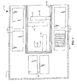
- FIG. 2 is a perspective view of an exemplary storage magazine for use with the media storage system, showing a cartridge referencing member mounted within each chamber;
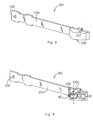
- FIG. 3 is a perspective view of an exemplary cartridge referencing member;
- FIG. 4 is a perspective view of another exemplary cartridge referencing member; and
- FIG. 5 is a simplified, front plan view of the storage magazine showing different sizes of data cartridges stored therein.
-
-
Apparatus 10 for retaining at least two different sizes ofdata cartridges 20 in astorage magazine 30, is shown and described herein as it could be used with amedia storage system 15. Briefly,media storage systems 15 are used to store large volumes of computer readable data. The computer readable data is typically stored onmultiple data cartridges 20 that are arranged in themedia storage system 15 in cartridge receiving devices (e.g.,storage magazines 30, read/writedevice 60, a mail slot (not shown), etc.). Thedata cartridges 20 are available in various sizes. For example, both LTO andDLT data cartridges 20 are commonly used with themedia storage system 15, wherein a DLT data cartridge 21 has a width approximately three millimeters greater than that of anLTO data cartridge 22. It is therefore desirable to store different sizes ofdata cartridges 20 in thesame storage magazine 30. The invention relates to a method and apparatus for retaining at least two different sizes ofdata cartridges 20 in thestorage magazine 30. - According to the teachings of the invention, the
media storage system 15 may include acartridge engaging assembly 40. The cartridgeengaging assembly 40 can be moved (e.g., in the direction of arrow 55) among thestorage magazines 30 and positioned adjacent thereto for accessing and storing thedata cartridges 20 therein. Thestorage magazine 30 may comprise aframe assembly 70 defining achamber 80 therein. That is, thechamber 80 is formed by two opposing partitions orside walls top wall 73, abottom wall 74, and arear wall 75. According to the invention, thechamber 80 is dimensioned to receive at least two different sizes ofdata cartridges 20 therein (e.g., LTO and DLT). Preferably, thechamber 80 is dimensioned to receive the largest size data cartridge 20 (e.g., DLT) for use with themedia storage system 15. As such, the larger size data cartridge 20 (e.g., DLT) and each smaller size data cartridge 20 (e.g., LTO) can be retained in thestorage magazine 30, as described in more detail below. Acartridge referencing member 90 is mounted or affixed to the frame assembly 70 (e.g., to side wall 72). As one of the different sizes ofdata cartridges 20 is inserted and received within thechamber 80, thecartridge referencing member 90 is resiliently displaced therein to accommodate the width of thedata cartridge 80, and urges thedata cartridge 20 toward, and retains thedata cartridge 20 in, a registration position. Also preferably, thecartridge referencing member 90 comprises an elongated arm 100 (e.g., a leaf spring) mounted at one end to theframe assembly 70 and having a cartridge biasing end opposite thereof. Preferably thecartridge referencing member 90 includes a buffer member on thetip portion 105 that is resiliently displaceable therewith. In one embodiment, thetip portion 105 may be provided with amember 107 for slidingly engaging thedata cartridge 20. In another embodiment, thetip portion 105 may comprise a roller 110 for rollingly engaging thedata cartridge 20. In either embodiment, thedata cartridge 20 contacts thetip portion 105 of theelongated arm 100 and is guided into thechamber 80 between thecartridge referencing member 90 and theopposing side wall 71 into a registration position therein. That is, as thedata cartridge 20 is received in thechamber 80, thecartridge referencing member 90 applies a biasing force to thedata cartridge 20 to urge and hold thedata cartridge 20 in a known registration position. As such, the biasing force keeps thedata cartridge 20 from floating into an unknown position within the wider interior of thechamber 80, where it could otherwise bind during insertion or removal, or fail to be picked by thecartridge engaging assembly 40. Preferably, thecartridge referencing member 90 biases thedata cartridge 20 against a reference surface of the chamber 80 (e.g.,side wall 71, a fin member (not shown), etc.) so that thedata cartridge 20 can be reliably engaged by thecartridge engaging assembly 40. Thus according to the invention, different sizes ofdata cartridges 20 are properly aligned and retained in thechamber 80. - In use, a system operator or the
cartridge engaging assembly 40 may insert one of the different sizes ofdata cartridges 20 into thechamber 80 formed in thestorage magazine 30. Preferably, thecartridge referencing member 90 is resiliently displaced within thechamber 80 as thedata cartridge 20 is received therein. As thedata cartridge 20 is received in thechamber 80, thecartridge referencing member 90 engages the inserteddata cartridge 20, and applies a biasing force to thedata cartridge 20. As such, the inserteddata cartridge 20 is retained in thechamber 80 of thestorage magazine 30 so that thedata cartridge 20 does not float into an unknown position within the wider interior of the chamber 80 (i.e., it is urged and held in a known registration position). - It is also important to recognize that according to the teachings of the invention, the
storage magazines 30 may be uniformly molded to retain at least two different sizes ofdata cartridges 20. In addition, thechambers 80 need not be formed to a precise tolerance. That is, the size of thechambers 80 can vary to some extent from one to another and such variation is accommodated for by thecartridge referencing member 90. As such, the invention reduces the cost of manufacture of thestorage magazines 30. In addition, neither the media storage system nor thestorage magazines 30 need to be retrofitted when differentsize data cartridges 20 are used therewith. Thus, the invention saves time and reduces the cost of operation of themedia storage system 15. - Having generally described an apparatus and method for retaining at least two different sizes of
data cartridges 20 in astorage magazine 30, and several advantages thereof, the apparatus and method will now be described in further detail. - The
apparatus 10 for retaining at least two different sizes ofdata cartridges 20 in astorage magazine 30 may comprise amedia storage system 15 such as that shown in FIG. 1. Themedia storage system 15 includesdata cartridges 20 stored in one ormore storage magazines 30. In use, a control system (not shown) moves acartridge engaging assembly 40 along a positioning rail 50 (in the directions of arrow 55) adjacent thedata cartridges 20. For purposes of illustration, thecartridge engaging assembly 40 is shown inpositions cartridge engaging assembly 40 is shown adjacent thedata cartridge 20 contained in thestorage magazine 30 atpositions write device 60 atposition 42. Thecartridge engaging assembly 40 transports thedata cartridge 20 about themedia storage system 15, for example, between the read/write device 60 and thestorage magazine 30. According to the invention, at least two different sizes ofdata cartridges 20 may be stored in thestorage magazine 30 without having to retrofit either themedia storage system 15 or thestorage magazines 30. - In use, a
data cartridge 20 to be stored in themedia storage system 15 may be inserted in a mail slot (not shown). For example, anew data cartridge 20 may be added to themedia storage system 15 or adata cartridge 20 that has been removed may be returned to thestorage magazine 30. In response, the control system moves thecartridge engaging assembly 40 along thepositioning rail 50 adjacent thedata cartridges 20. Where adata cartridge 20 has been added to themedia storage system 15, thecartridge engaging assembly 40 retrieves thedata cartridge 20 from the mail slot and delivers thedata cartridge 20 to anavailable storage magazine 30. Similarly, thecartridge engaging assembly 40 may return thedata cartridge 20 from the read/write device 60 to thestorage magazine 30. For example, thecartridge engaging assembly 40 may transport thedata cartridge 20 to the next available chamber 80 (see FIG. 2) in one of thestorage magazines 30. Or for example, thecartridge engaging assembly 40 may transport thedata cartridge 20 to aspecific chamber 80 in one of the storage magazines 30 (e.g., based on originating department, inventoryschedule, data classification, etc.). According to the invention, at least two different sizes ofdata cartridges 20 can be delivered to anyavailable chamber 80 in thestorage magazine 30, for reasons explained in more detail below. - The
storage magazine 30 shown in FIG. 2 may comprise aframe assembly 70 that defines a cavity orchamber 80 sized to receive thedata cartridge 20 therein. That is, theframe assembly 70 includes opposing partitions orside walls top wall 73, abottom wall 74, and arear wall 75, that define one ormore chambers 80 in thestorage magazine 30. Preferably, thechamber 80 is over-sized. That is, thechamber 80 is formed to receive the largest data cartridge 20 (e.g., DLT) therein. As such, each smaller size data cartridge 20 (e.g., LTO) can also be received therein. Acartridge referencing member 90 is mounted to the frame assembly 70 (e.g., on side wall 72). Thecartridge referencing member 90 is resiliently displaceable within thechamber 80 as thedata cartridge 20 is received therein. Thus, as thedata cartridge 20 is received in thechamber 80, thecartridge referencing member 90 flexes to allow thedata cartridge 20 to be received therein. In addition, thecartridge referencing member 90 applies a biasing force to thedata cartridge 20 to align the data cartridge in thechamber 80 and to keep thenarrower data cartridge 20 from floating into an unknown position within the wider interior of the chamber 80 (i.e., it is retained in a known registration position therein). Thecartridge referencing member 90 may bias thedata cartridge 20 against a reference surface of the chamber 80 (e.g., side wall 71). Thus, thedata cartridge 20 is aligned against the reference surface so that different sizes ofdata cartridges 20 may be reliably engaged by thecartridge engaging assembly 40. - It is understood that the
storage magazine 30 may take any suitable form. For example, thestorage magazine 30 need not be removable and may instead be integrally formed or permanently mounted therein, a series of partitions within themedia storage system 15, etc. In addition, any number ofchambers 80 can be formed therein. Also for example, theside walls walls - It is also understood that the
cartridge referencing member 90 may be mounted in any suitable position within thechamber 80. Preferably, thecartridge referencing member 90 is mounted on theside wall 72 near theback wall 75 and the cartridge biasing end thus applies a biasing force to the front portion of the data cartridge 20 (i.e., near the opening of the chamber 80), as shown in FIG. 2. However, thecartridge referencing member 90 may be mounted, for example, to theside wall 72 near the opening of thechamber 80 and the cartridge biasing end thus applies the biasing force against the rear portion of the data cartridge 20 (i.e., near the back wall 75). In another embodiment, thecartridge referencing member 90 may also be, or may be instead, mounted to thetop wall 73 and/or to thebottom wall 74 to accommodatedata cartridges 20 of various heights. In yet another embodiment, acartridge referencing member 90 may be mounted to theback wall 75 to accommodatedata cartridges 20 of various depths. In addition, it is further understood that more than onecartridge referencing member 90 may be mounted to more than one of the walls 71-75 that form thechamber 80. For example, acartridge referencing member 90 may be mounted to bothside walls side wall 72 and thetop wall 73, etc. - The
cartridge referencing member 90 is preferably mounted within thechamber 80 within a slot formed in theside wall 72, as shown in FIG. 2. As such, additional fasteners are not required to affix thecartridge referencing member 90 to thechamber 80. In addition, thecartridge referencing member 90 is preferably exposed for several inches along theside wall 72 within thechamber 80 and is flexible along the length thereof. A longer exposed span, as such, reduces the force applied to thedata cartridge 20 so that it may be more readily picked by thecartridge engaging assembly 40. Preferably, thecartridge referencing member 90 only applies sufficient force to retain thedata cartridge 20 in thechamber 80 when thestorage magazine 30 is being transported external to themedia storage system 15, and does not unduly burden thecartridge engaging assembly 40 during the insertion and/or removal ofdata cartridges 20. - It is understood that the
cartridge referencing member 90 may be mounted in any suitable manner within thechamber 80. For example, in another embodiment, thecartridge referencing member 90 may be mounted in onechamber 85 with thetip portion 105 extending through theside wall 72 and into anotherchamber 80. For example, one end or mountingportion 102 of theelongated arm 100 may be mounted to oneside 81 of theside wall 72 in onechamber 85 and extend substantially along the oneside 81. An opening (not shown) may be formed in theside wall 72 between thefirst side 81 and asecond side 82 to receive thetip portion 105 therethrough. As such, thetip portion 105 extends through theside wall 72 to engage adata cartridge 20 that is inserted into thechamber 80. The opening formed in theside wall 72 may also be elongated so that a portion of theelongated arm 100 also extends therethrough and into thechamber 80. - It is also understood that the
cartridge referencing member 90 may be mounted to theframe assembly 70 of thestorage magazine 30 using any suitable means. For example, a mounting post (not shown) may be molded as part of theside wall 72 so that theelongated arm 100 may be fitted thereon at one end 102 (FIG. 3 and FIG. 4). A clip can also be slipped over the mounting post to further secure theelongated arm 100 thereto. Thecartridge referencing member 90 may also be mounted using other suitable means such as a rivet, screw, glue, etc. Indeed theelongated arm 100 may even be molded as part of the chamber 80 (e.g., the side wall 72). - An exemplary embodiment of the
cartridge referencing member 90 is shown in more detail in FIG. 3. Thecartridge referencing member 90 may comprise anelongated arm 100 with atip portion 105 mounted to the cartridge biasing end thereof. Theelongated arm 100 may be, for example, a leaf spring attached at oneend 102 to the side wall 72 (see FIG. 2). Thetip portion 105 may be, for example, aridge member 107 that slidingly engages thedata cartridge 20 as it is inserted into thechamber 80 to guide thedata cartridge 20 therein. - It is understood that although the
elongated arm 100 is preferably stainless steel, theelongated arm 100 can be constructed of any resilient material (e.g., plastic). In addition, although theelongated arm 100 is preferably four inches long, it may be any suitable length. The design of theelongated arm 100 will depend on design considerations, such as, but not limited to, the desired resiliency, elasticity, and durability thereof. - Another exemplary embodiment of the
cartridge referencing member 90 is shown in FIG. 4, again comprising anelongated arm 100 mounted at oneend 102 to theside wall 72 of thechamber 80, and atip portion 105 mounted to the cartridge biasing end thereof. In the embodiment shown in FIG. 4, thetip portion 105 may be provided with a roller 110 rotatably mounted about anaxis 109 between opposingsupport arms 112 thereof. As such, thetip portion 105 may rollingly engage thedata cartridge 20 with the roller 110 as thedata cartridge 20 is received within thechamber 80. - It is understood that the roller 110 may be manufactured of any suitable material, such as, but not limited to metal or plastic. In addition, the roller 110 may be cylindrical or spherical (e.g., a ball bearing). Similarly, the roller 110 need not be supported between opposing
support arms 112. For example, theroller 112 may be attached to asingle support arm 112. Or for example, where the roller 110 is spherical, the roller may be held in support similar to the ball point in a pen. It is also understood that a plurality of rollers 110 may be positioned adjacent one another, side-by-side, or along the length of theelongated arm 100. - It is understood that the
tip portion 105 may be any suitable shape and may be manufactured of any suitable material and is optionally provided withmember 107, 110. In addition, where provided, themember 107, 110 may be integrally formed as part ofcartridge referencing member 90, or separately formed and mounted thereto. Preferably, themember 107, 110 is a buffer member (e.g., a plastic tab, a foam cushion, a rubber coating, a roller, etc.). The buffer member contacts and engages thedata cartridge 20 so that thedata cartridge 20 does not directly contact theelongated arm 100. As such, the buffer member provides protection against damage and wear to thedata cartridge 20 as it is inserted and removed from thechamber 80. However in other embodiments, themember 107, 110 need not serve as a buffer and may instead serve as a guide, etc. - It is further understood that the embodiments of the
cartridge referencing member 90 shown in FIG. 3 and FIG. 4 are merely illustrative of the invention. Other embodiments are also contemplated as being within the scope of the invention. Other embodiments may include, for example, a cartridge referencing member that is mounted in the center of theelongated arm 100 with a cartridge biasing end on each side thereof, etc. - FIG. 5 is a simplified front plan view of the
storage magazine 30 showing both a DLT data cartridge 21 and anLTO data cartridge 22 stored therein. The DLT data cartridge 21 is transported by thecartridge engaging assembly 40 adjacent anavailable chamber 80 in thestorage magazine 30. Thecartridge engaging assembly 40 then inserts the DLT data cartridge 21 into thechamber 80. As the DLT data cartridge 21 is received in thechamber 80, the DLT data cartridge 21 contacts thetip portion 105 of thecartridge referencing member 90. For example, the DLT data cartridge 21 may contact theridge member 107 or the roller 110 on the tip portion 105 (FIG. 3 and FIG. 4, respectively). In any event, the DLT data cartridge 21 is engaged by thecartridge referencing member 90, which resiliently deflects to allow the DLT data cartridge 21 to be received in thechamber 80 of thestorage magazine 30. As the DLT data cartridge 21 is received in thechamber 80, the cartridge referencing member 90 (i.e., the cartridge biasing end thereof) applies a biasing force against the DLT data cartridge 21 to bias it in a registration position (e.g., against the opposing side wall 71) to keep thedata cartridge 20 from floating into an unknown position within the interior of thechamber 80. As such, the DLT data cartridge 21 is retained in the chamber 80 (e.g., against the reference surface 71) of thestorage magazine 30. Once inserted into thechamber 80, thecartridge engaging assembly 40 disengages from the DLT data cartridge 21 and is removed therefrom. TheLTO data cartridge 22 can be similarly inserted into anavailable chamber 80 in thestorage magazine 30 and aligned and retained therein via the biasing force applied thereto by thecartridge referencing member 90. Thus, various size data cartridges (e.g., DLT data cartridge 21 and LTO data cartridge 22) are aligned and retained within thesame storage magazine 30 and can be reliably removed by thecartridge engaging assembly 40. - It should be noted that although the apparatus and method of the present invention is illustrated using a particular
media storage system 15, the teachings of the invention may be utilized in any of a wide range of media storage systems now known in the art or that may be developed in the future for storing one ormore data cartridges 20. Accordingly, the present invention should not be regarded as limited to the particularmedia storage system 15 shown and described herein. It should also be noted that while the invention is shown and described herein as it could be used to store and retrieve LTO andDLT data cartridges 20 having standard sizes and configurations, it is not limited to any particular type or style of data cartridge. Consequently, the present invention should not be regarded as limited to use with themedia storage system 15 for the LTO andDLT data cartridges 20 shown and described herein. - While illustrative and presently preferred embodiments of the invention have been described in detail herein, it is to be understood that the inventive concepts may be otherwise variously embodied and employed, and that the appended claims are intended to be construed to include such variations, except as limited by the prior art.
Claims (10)
- An apparatus (10) for retaining data cartridges (20) in a storage magazine (30), comprising:a frame assembly (70) defining a chamber (80) in the storage magazine, said chamber dimensioned to receive the largest of at least two different sizes of data cartridges therein;a cartridge referencing member (90) mounted to said frame assembly, said cartridge referencing member resiliently displaceable within the chamber, said cartridge referencing member applying a biasing force to a data cartridge received therein to retain said received data cartridge in a registration position within said chamber.
- The apparatus (10) of claim 1, wherein said cartridge referencing member (90) comprises an elongated arm (100) mounted to said frame assembly.
- The apparatus (10) of claim 1, wherein said cartridge referencing member (90) comprises an elongated arm (100) having a mounting portion (102) and a tip portion (105), the mounting portion of said elongated arm being mounted to said frame assembly (70) and the tip portion contacting said received data cartridge (20).
- The apparatus of (10) claim 3, further comprises a buffer member mounted to the tip portion (105) of said elongated arm (100) so that said buffer member contacts said received data cartridge.
- The apparatus (10) of claim 3, further comprising a ridge member (107) mounted to the tip portion (105) of said elongated arm (100) so that said ridge member contacts said received data cartridge (20).
- The apparatus (10) of claim 3, further comprising a roller (110) mounted to the tip portion (105) of said elongated arm (100) so that said roller contacts said received data cartridge (20).
- The apparatus of claim 1, wherein said received data cartridge (20) is biased against a reference surface.
- A method for retaining data cartridges (20) in a storage magazine (30), comprising:inserting one of at least two different sizes of data cartridges into a chamber (80) formed in said storage magazine; andapplying a biasing force to said inserted data cartridge, thereby retaining said inserted data cartridge in a registration position in the chamber of the storage magazine.
- The method of claim 8, wherein applying said biasing force retains said inserted data cartridge (20) against an opposing side wall (71) of the chamber (80).
- The method of claim 8, further comprising resiliently displacing a cartridge referencing member (90) within the chamber (80) as said one of the at least two different sizes of data cartridges (20) is inserted therein, said biasing force applied to said inserted data cartridge within said chamber by said cartridge referencing member (100).
Applications Claiming Priority (2)
| Application Number | Priority Date | Filing Date | Title |
|---|---|---|---|
| US791107 | 2001-02-22 | ||
| US09/791,107 US6621654B2 (en) | 2001-02-22 | 2001-02-22 | Apparatus and method for retaining different sizes of data cartridges in a storage magazine |
Publications (1)
| Publication Number | Publication Date |
|---|---|
| EP1235217A1 true EP1235217A1 (en) | 2002-08-28 |
Family
ID=25152709
Family Applications (1)
| Application Number | Title | Priority Date | Filing Date |
|---|---|---|---|
| EP01121586A Withdrawn EP1235217A1 (en) | 2001-02-22 | 2001-09-10 | Apparatus and method for retaining different sizes of data cartridges in a storage magazine |
Country Status (3)
| Country | Link |
|---|---|
| US (1) | US6621654B2 (en) |
| EP (1) | EP1235217A1 (en) |
| JP (1) | JP2002251812A (en) |
Cited By (2)
| Publication number | Priority date | Publication date | Assignee | Title |
|---|---|---|---|---|
| WO2003071542A1 (en) * | 2002-02-21 | 2003-08-28 | International Business Machines Corporation | Data-cartridge case adapted for dual-format applications |
| EP1713073A1 (en) * | 2005-04-13 | 2006-10-18 | Quantum Corporation | Universal housing for holding storage devices |
Families Citing this family (5)
| Publication number | Priority date | Publication date | Assignee | Title |
|---|---|---|---|---|
| US6985328B2 (en) * | 2002-07-09 | 2006-01-10 | Quantum Corporation | One and three quarters inch form factor tape cartridge autoloader |
| US7508621B2 (en) * | 2003-06-26 | 2009-03-24 | Spectra Logic Corporation | Magazine-based data cartridge library |
| JP4095048B2 (en) * | 2004-07-28 | 2008-06-04 | 富士通株式会社 | Library device |
| JP2007080392A (en) * | 2005-09-14 | 2007-03-29 | Mitsumi Electric Co Ltd | Tape cartridge autoloader |
| US11475922B2 (en) * | 2021-02-09 | 2022-10-18 | Quantum Corporation | Storage apparatus for shuffling removable storage media |
Citations (5)
| Publication number | Priority date | Publication date | Assignee | Title |
|---|---|---|---|---|
| EP0288165A2 (en) * | 1987-03-26 | 1988-10-26 | Matsushita Electric Industrial Co., Ltd. | Automatic exchanging system of tape cassettes |
| EP0566351A2 (en) * | 1992-04-13 | 1993-10-20 | Sony Corporation | Automatic cassette changer |
| US5652682A (en) * | 1994-11-11 | 1997-07-29 | M4 Data Limited | Apparatus for loading and unloading cartridges |
| US5739978A (en) * | 1996-05-17 | 1998-04-14 | Exabyte Corporation | Cartridge handling system with moving I/O drive |
| GB2352865A (en) * | 1999-05-17 | 2001-02-07 | Hewlett Packard Co | Picker indexing and multimedia cartridge referencing spring |
Family Cites Families (14)
| Publication number | Priority date | Publication date | Assignee | Title |
|---|---|---|---|---|
| US3643962A (en) | 1969-03-18 | 1972-02-22 | Qatron Corp | Magnetic tape playing and changing apparatus |
| US3730535A (en) | 1971-04-23 | 1973-05-01 | Motorola Inc | Cartridge locking mechanism |
| US3735989A (en) | 1972-05-12 | 1973-05-29 | Motorola Inc | Cartridge locking mechanism with adjustable tension |
| FR2280952A1 (en) | 1974-07-30 | 1976-02-27 | Staar Sa | CASSETTE LOADING DEVICE FOR MAGNETIC TAPE RECORDING AND READING DEVICES |
| JPS6361482A (en) | 1986-09-01 | 1988-03-17 | Fujitsu Ltd | Cartridge magazine |
| JPH01118259A (en) | 1987-10-30 | 1989-05-10 | Sankyo Seiki Mfg Co Ltd | Tape cartridge positioning mechanism |
| US5021902A (en) | 1988-02-17 | 1991-06-04 | Hitachi, Ltd. | Tape changer for loading and unloading a magazine of magnetic tape cartridges |
| DE68917620T2 (en) * | 1988-03-23 | 1995-04-20 | Sony Corp | Automatic video cassette changer. |
| JP3374422B2 (en) * | 1992-11-09 | 2003-02-04 | ソニー株式会社 | Cassette autochanger |
| US5596556A (en) | 1993-02-18 | 1997-01-21 | Hewlett-Packard Company | Linear displacement and support apparatus for use in a cartridge handling system |
| JP2798059B2 (en) | 1996-06-27 | 1998-09-17 | 日本電気株式会社 | Disk cartridge storage device |
| DE69814233T2 (en) | 1997-06-10 | 2003-11-20 | Alps Electric Co Ltd | A magnetic recording / reproducing apparatus, |
| US6160786A (en) | 1998-03-20 | 2000-12-12 | Hewlett-Packard Company | Cartridge engaging assembly with rack drive thumb actuator system |
| US6025972A (en) | 1998-03-20 | 2000-02-15 | Hewlett-Packard Company | Multi-plane translating cartridge handling system |
-
2001
- 2001-02-22 US US09/791,107 patent/US6621654B2/en not_active Expired - Fee Related
- 2001-09-10 EP EP01121586A patent/EP1235217A1/en not_active Withdrawn
-
2002
- 2002-02-15 JP JP2002038048A patent/JP2002251812A/en active Pending
Patent Citations (5)
| Publication number | Priority date | Publication date | Assignee | Title |
|---|---|---|---|---|
| EP0288165A2 (en) * | 1987-03-26 | 1988-10-26 | Matsushita Electric Industrial Co., Ltd. | Automatic exchanging system of tape cassettes |
| EP0566351A2 (en) * | 1992-04-13 | 1993-10-20 | Sony Corporation | Automatic cassette changer |
| US5652682A (en) * | 1994-11-11 | 1997-07-29 | M4 Data Limited | Apparatus for loading and unloading cartridges |
| US5739978A (en) * | 1996-05-17 | 1998-04-14 | Exabyte Corporation | Cartridge handling system with moving I/O drive |
| GB2352865A (en) * | 1999-05-17 | 2001-02-07 | Hewlett Packard Co | Picker indexing and multimedia cartridge referencing spring |
Cited By (4)
| Publication number | Priority date | Publication date | Assignee | Title |
|---|---|---|---|---|
| WO2003071542A1 (en) * | 2002-02-21 | 2003-08-28 | International Business Machines Corporation | Data-cartridge case adapted for dual-format applications |
| US6900964B2 (en) | 2002-02-21 | 2005-05-31 | International Business Machines Corporation | Data-cartridge case adapted for dual-format applications |
| EP1713073A1 (en) * | 2005-04-13 | 2006-10-18 | Quantum Corporation | Universal housing for holding storage devices |
| US7486473B2 (en) | 2005-04-13 | 2009-02-03 | Quantum Corporation | Universal housing for holding storage devices |
Also Published As
| Publication number | Publication date |
|---|---|
| JP2002251812A (en) | 2002-09-06 |
| US6621654B2 (en) | 2003-09-16 |
| US20020114103A1 (en) | 2002-08-22 |
Similar Documents
| Publication | Publication Date | Title |
|---|---|---|
| US7474497B2 (en) | Deep slot magazine storage library | |
| EP0709849A2 (en) | Disk cartridge magazines | |
| US20070230036A1 (en) | Deep storage slot with a constant spring force | |
| US6621654B2 (en) | Apparatus and method for retaining different sizes of data cartridges in a storage magazine | |
| US20020006030A1 (en) | Universal media module | |
| CA1254174A (en) | System for storing and dispensing magnetic tape cartridges | |
| US6042205A (en) | Media holding device incorporating a media locking mechanism | |
| US6259579B1 (en) | Picker indexing and multimedia cartridge referencing spring | |
| US4651882A (en) | System for storing and dispensing magnetic tape cartridges | |
| US7019940B2 (en) | Universal cartridge magazine system and method | |
| US7312947B2 (en) | Magnetic tape cartridge storage apparatus with lock and release device | |
| JP2007213811A (en) | Medium-detection system and method for identifying type of data cartridge | |
| JP3658446B2 (en) | cartridge | |
| US6244677B1 (en) | Array and method for standardizing cartridge location within storage cells of a data storage library | |
| US7788683B2 (en) | Data storage cartridge and system including non-tape storage medium | |
| US6669431B1 (en) | Robotic docking apparatus for a cartridge library system having a cartridge storage array | |
| US10510372B1 (en) | Mechanical retention and retrieval for tape storage cartridge | |
| US6233215B1 (en) | Door assembly for a cartridge handling device | |
| US6480443B1 (en) | Method and system for restraining a cartridge within an insertable magazine | |
| JP2004014097A (en) | Storage magazine with little overhead | |
| US8139315B2 (en) | Storage slot for data storage cartridges of differing dimensions | |
| US6676070B2 (en) | Backward compatible tape support | |
| US6392835B1 (en) | Information recording medium library apparatus in which the position of the drive is fixed in the sub body of the apparatus | |
| US8116028B2 (en) | Cartridge loading devices | |
| US20170301374A1 (en) | Positive latching of tape cartridges in tape library magazines |
Legal Events
| Date | Code | Title | Description |
|---|---|---|---|
| PUAI | Public reference made under article 153(3) epc to a published international application that has entered the european phase |
Free format text: ORIGINAL CODE: 0009012 |
|
| AK | Designated contracting states |
Kind code of ref document: A1 Designated state(s): AT BE CH CY DE DK ES FI FR GB GR IE IT LI LU MC NL PT SE TR |
|
| AX | Request for extension of the european patent |
Free format text: AL;LT;LV;MK;RO;SI |
|
| 17P | Request for examination filed |
Effective date: 20020822 |
|
| 17Q | First examination report despatched |
Effective date: 20030325 |
|
| AKX | Designation fees paid |
Designated state(s): DE FR GB |
|
| STAA | Information on the status of an ep patent application or granted ep patent |
Free format text: STATUS: THE APPLICATION HAS BEEN WITHDRAWN |
|
| 18W | Application withdrawn |
Effective date: 20040401 |