EP1225577A2 - Apparatus and method for retrieving data related to a data cartridge - Google Patents
Apparatus and method for retrieving data related to a data cartridge Download PDFInfo
- Publication number
- EP1225577A2 EP1225577A2 EP01306367A EP01306367A EP1225577A2 EP 1225577 A2 EP1225577 A2 EP 1225577A2 EP 01306367 A EP01306367 A EP 01306367A EP 01306367 A EP01306367 A EP 01306367A EP 1225577 A2 EP1225577 A2 EP 1225577A2
- Authority
- EP
- European Patent Office
- Prior art keywords
- data
- cartridge
- transponder
- reader
- access device
- Prior art date
- Legal status (The legal status is an assumption and is not a legal conclusion. Google has not performed a legal analysis and makes no representation as to the accuracy of the status listed.)
- Granted
Links
- 238000000034 method Methods 0.000 title claims abstract description 13
- 230000007246 mechanism Effects 0.000 claims abstract description 29
- 210000003813 thumb Anatomy 0.000 claims description 4
- 230000003213 activating effect Effects 0.000 claims description 3
- 238000012545 processing Methods 0.000 claims description 3
- 230000005540 biological transmission Effects 0.000 description 12
- 230000004044 response Effects 0.000 description 6
- 238000013461 design Methods 0.000 description 4
- 238000013500 data storage Methods 0.000 description 3
- 238000005516 engineering process Methods 0.000 description 3
- 230000006870 function Effects 0.000 description 3
- 238000001514 detection method Methods 0.000 description 2
- 210000003811 finger Anatomy 0.000 description 2
- 239000000758 substrate Substances 0.000 description 2
- 230000001133 acceleration Effects 0.000 description 1
- 230000004913 activation Effects 0.000 description 1
- 239000000853 adhesive Substances 0.000 description 1
- 230000001070 adhesive effect Effects 0.000 description 1
- 239000000872 buffer Substances 0.000 description 1
- 230000008859 change Effects 0.000 description 1
- 238000004891 communication Methods 0.000 description 1
- 230000003750 conditioning effect Effects 0.000 description 1
- 238000012937 correction Methods 0.000 description 1
- 230000005684 electric field Effects 0.000 description 1
- 230000001939 inductive effect Effects 0.000 description 1
- 230000003287 optical effect Effects 0.000 description 1
- 230000000717 retained effect Effects 0.000 description 1
- 238000012546 transfer Methods 0.000 description 1
Images


Classifications
-
- G—PHYSICS
- G11—INFORMATION STORAGE
- G11B—INFORMATION STORAGE BASED ON RELATIVE MOVEMENT BETWEEN RECORD CARRIER AND TRANSDUCER
- G11B23/00—Record carriers not specific to the method of recording or reproducing; Accessories, e.g. containers, specially adapted for co-operation with the recording or reproducing apparatus ; Intermediate mediums; Apparatus or processes specially adapted for their manufacture
- G11B23/02—Containers; Storing means both adapted to cooperate with the recording or reproducing means
- G11B23/03—Containers for flat record carriers
- G11B23/0301—Details
- G11B23/0302—Auxiliary features
- G11B23/0305—Semiconductor memories
-
- G—PHYSICS
- G11—INFORMATION STORAGE
- G11B—INFORMATION STORAGE BASED ON RELATIVE MOVEMENT BETWEEN RECORD CARRIER AND TRANSDUCER
- G11B15/00—Driving, starting or stopping record carriers of filamentary or web form; Driving both such record carriers and heads; Guiding such record carriers or containers therefor; Control thereof; Control of operating function
- G11B15/02—Control of operating function, e.g. switching from recording to reproducing
- G11B15/05—Control of operating function, e.g. switching from recording to reproducing by sensing features present on or derived from record carrier or container
- G11B15/06—Control of operating function, e.g. switching from recording to reproducing by sensing features present on or derived from record carrier or container by sensing auxiliary features on record carriers or containers, e.g. to stop machine near the end of a tape
- G11B15/07—Control of operating function, e.g. switching from recording to reproducing by sensing features present on or derived from record carrier or container by sensing auxiliary features on record carriers or containers, e.g. to stop machine near the end of a tape on containers
-
- G—PHYSICS
- G11—INFORMATION STORAGE
- G11B—INFORMATION STORAGE BASED ON RELATIVE MOVEMENT BETWEEN RECORD CARRIER AND TRANSDUCER
- G11B15/00—Driving, starting or stopping record carriers of filamentary or web form; Driving both such record carriers and heads; Guiding such record carriers or containers therefor; Control thereof; Control of operating function
- G11B15/675—Guiding containers, e.g. loading, ejecting cassettes
- G11B15/68—Automatic cassette changing arrangements; automatic tape changing arrangements
- G11B15/682—Automatic cassette changing arrangements; automatic tape changing arrangements with fixed magazines having fixed cassette storage cells, e.g. in racks
- G11B15/6835—Automatic cassette changing arrangements; automatic tape changing arrangements with fixed magazines having fixed cassette storage cells, e.g. in racks the cassettes being transferred to a fixed recorder or player using a moving carriage
-
- G—PHYSICS
- G11—INFORMATION STORAGE
- G11B—INFORMATION STORAGE BASED ON RELATIVE MOVEMENT BETWEEN RECORD CARRIER AND TRANSDUCER
- G11B17/00—Guiding record carriers not specifically of filamentary or web form, or of supports therefor
- G11B17/22—Guiding record carriers not specifically of filamentary or web form, or of supports therefor from random access magazine of disc records
- G11B17/225—Guiding record carriers not specifically of filamentary or web form, or of supports therefor from random access magazine of disc records wherein the disks are transferred from a fixed magazine to a fixed playing unit using a moving carriage
Definitions
- the present invention pertains to retrieving data related to a data cartridge in a media storage system, for example for retrieving the related data from a transponder attached to the data cartridge using a reader attached to a cartridge access device of the media storage system.
- Media storage systems are commonly used to store data cartridges and to retrieve desired data cartridges so that computer readable data may be written to or read from the data cartridges. As such, large volumes of computer readable data can be stored on numerous data cartridges and accessed by a single computer or by multiple computers connected to the media storage system over a network.
- Such media storage systems are often referred to as "juke box” storage systems, and may include a cartridge storage rack or "magazine” and a cartridge read/write device.
- the cartridge storage rack serves as a storage location for the data cartridges. Multiple storage racks are commonly arranged so that they form one or more vertical stacks.
- the media storage system also includes a cartridge access device for moving among and accessing the data cartridges stored therein.
- a control system moves the cartridge access device among the storage racks until the cartridge access device is positioned adjacent the requested data cartridge. The cartridge access device then removes the data cartridge from the storage rack and delivers it to the read/write device for the computer to access the computer readable data stored thereon.
- the control system must be able to locate or otherwise recognise the requested data cartridge in the storage rack.
- One solution is to maintain a "map" indicating the identity and position of each data cartridge in the storage rack.
- the map must be periodically updated to ensure that the map contains accurate data. Events that will usually indicate a need to update the map include, but are not limited to, adding or removing a data cartridge from the system, operating a cartridge "mail slot" or a system power cycle (that is, if the data storage system is turned off).
- the map when the computer readable data contained on an existing data cartridge in the storage rack is changed, the map must be updated to reflect the changed content of the data cartridge at that position.
- Other examples where the map must be updated include, moving a data cartridge to another position in the storage rack, adding another storage rack to the media storage system, or otherwise changing the configuration of the system.
- One solution to maintaining the map is to manually inventory the media storage system each time a change occurs. However, this is time consuming and prone to human error.
- Another solution for maintaining the map is to label each data cartridge stored in the media storage system with a machine-readable code, such as a bar code label and to read the bar code label with a scanner attached to the cartridge access device.
- the data cartridges may be positioned in the storage rack in close proximity to one another. Therefore, the cartridge access device and the data cartridge must be carefully aligned to correctly scan the bar code.
- the bar code only contains limited information (for example, an identification number), and cannot be rewritten. Any further information must be stored separately (for example, in a "look-up" table or other suitable database). For example, a "look-up" table may associate the identification number contained on the bar code with a date, data format, data type, and so on.
- the present invention seeks to provide improved data retrieval.
- the present invention can provide a system to store the cartridge identification and other data related to the data cartridge.
- the system can store the cartridge identification and other data without the need for separate "lookup" tables.
- Apparatus 10 for retrieving data related to a data cartridge 20 is shown and described herein as it could be used with a data or media storage system 15.
- media storage systems 15 are used to store large volumes of computer readable data.
- the computer readable data is typically stored on multiple data cartridges 20 that are arranged in the media storage system 15 on cartridge storage racks 30. It is therefore desirable to identify individual data cartridges 20 and the data stored thereon with as much information that is possible without having physically to remove the data cartridge 20 from the cartridge storage rack 30.
- the described system provides a method and apparatus for reading data related to the data cartridge 20.
- the media storage system 15 may include a cartridge access device 40.
- the cartridge access device 40 can be moved among the cartridge storage racks 30 and positioned adjacent a data cartridge 20 to access the data cartridges 20 stored therein.
- a reader 140 is mounted to the cartridge access device 40 and data related to the data cartridge 20 (for example, cartridge ID, user, data origin, date, data format, load count, and so on) is stored in a transponder 150 mounted thereon.
- data related data can be read from each data cartridge 20 as the cartridge access device 40 is moved among the storage racks 30 and each cartridge stored therein can be automatically inventoried.
- the related data for example, cartridge ID, data format, date, and so on
- the related data can be read from each data cartridge 20 as the cartridge access device 40 is moved among the storage racks 30 and the related data displayed or stored in a database for later use.
- the requested data cartridge 20 is readily recognised, removed from the storage rack 30, and delivered to the read/write device 60 for access to the computer readable data stored thereon.
- a data cartridge 20 is placed in a mail slot (that is, a drop-off point, not shown) in the media storage system 15
- the related data is read to identify the data cartridge 20 so that the data cartridge 20 is returned or entered at the appropriate position in the storage rack 30.
- the user may search for a data cartridge 20 as the cartridge access device 40 is moved among the storage racks 30 and the related data is read from the data cartridge 20 and transmitted to the user.
- the method preferably includes positioning the cartridge access device 40, and hence the reader 140, adjacent the data cartridge 20 and activating the transponder 150.
- the activated transponder 150 transmits a data signal containing the data related to the data cartridge 20, which is received at the reader and processed by the controller 147.
- the related data may be displayed for a user browsing the media storage system 15, used to create an inventory for immediate or later use, used to identify a requested data cartridge 20, and so on.
- the data cartridges 20 may be closely packed in the storage rack 30. Therefore, the likelihood exists for interference with transponders 150 on nearby data cartridges 20.
- the system addresses this concern by preferably mounting the reader 140 to a cartridge plunge mechanism 90 movable between extended and retracted positions within the cartridge access device 40.
- the reader 140 can be extended toward the data cartridge 20 or retracted therefrom for more accurate positioning.
- mounting the reader 140 to the movable cartridge plunge mechanism 90 allows the reader 140 to be positioned near the data cartridge 20 without the reader 140 physically contacting the transponder 150. As such, the reader 140 and the transponder 150 are protected against physical wear.
- the mechanical tolerances may vary from one media storage system 15 to another. Indeed, the mechanical tolerances may vary within a single media storage system 15 between one storage rack 30 and another or even between one data cartridge 20 and another. Therefore, in media storage systems 15 where mechanical tolerances vary, the reader 140 may not be sufficiently close to the transponder 150 in some instances.
- the system addresses this concern by individually adjusting the position of the reader 140 at each data cartridge 20 using the cartridge plunge mechanism 90. That is, the cartridge plunge mechanism 90, and hence the reader 140 mounted thereto, can be extended or retracted to maintain the desired distance between the reader 140 and the transponder 150 at each data cartridge 20, regardless of the variability in the mechanical tolerances of the media storage system 15.
- the apparatus 10 for reading data related to the data cartridges 20 may comprise a media storage system 15 such as that shown in Figure 1.
- the media storage system 15 includes data cartridges 20 stored in one or more storage racks 30.
- a control system (not shown) moves a cartridge access device 40 along a positioning rail 50 adjacent the data cartridges 20.
- data related to a data cartridge 20 can be read (that is, using standard protocols) when the cartridge access device 40 is positioned adjacent the data cartridge 20.
- the cartridge access device 40 is shown in positions 41, 42, and 43 in Figure 1.
- the cartridge access device 40 is shown adjacent the data cartridge 20 contained in the storage rack 30 at positions 41 and 43, and is shown adjacent the read/write device 60 at position 42.
- a computer linked to the media storage system 15 (for example, via a direct connection, remote connection, network connection, and so on) may issue a request to access a data cartridge 20 or to inventory the data cartridges 20 stored in the media storage system 15.
- the control system moves the cartridge access device 40 along the positioning rail 50 adjacent the data cartridges 20.
- the control system positions the cartridge access device 40 adjacent the requested data cartridge 20, and signals the cartridge access device 40 to withdraw the data cartridge 20 from the storage rack 30 and to carry it to the read/write device 60 where the linked computer can access the computer readable data stored thereon.
- the requested data cartridge 20 can be readily identified from the data related to the data cartridge 20 and read at the cartridge access device 40, as explained in more detail below.
- the related data is read from each data cartridge 20 as the access device 40 is moved about the media storage device 15. It is understood that the system can provide both reading the related data from each data cartridge 20 by stopping the cartridge access device 40 adjacent each data cartridge 20 and/or "on the fly" as the cartridge access device 40 is moving along the positioning rail 50.
- the cartridge access device 40 shown in Figure 2 may include a frame assembly 70 that defines a chamber or cavity 80 sized to receive the data cartridge 20 therein (for example, for carrying it to the read/write device 60).
- a cartridge plunge mechanism 90 is slidably mounted to the frame assembly 70 so that the cartridge plunge mechanism 90 may be moved toward (that is, extended) and away (that is, retracted) from the cartridge access end 75 of the frame assembly 70, generally in the directions indicated by arrows 93 and 97, respectively.
- the reader 140 can be mounted to the cartridge plunge mechanism 90 and thus be further positioned near the data cartridge 20 by moving the cartridge plunge mechanism 90 between the extended and retracted positions.
- the cartridge plunge mechanism 90 may also be provided with a finger assembly 100 configured to engage the data cartridge 20.
- the finger assembly 100 allows the cartridge plunge mechanism 90 to engage and withdraw the data cartridge 20 from the storage rack 30 and the read/write device 60 when so requested.
- An optional encoder system may provide an output signal from which information may be derived about the position of the cartridge plunge mechanism 90 within the frame assembly 70 (for example, along the path indicated by arrows 93, 97).
- the encoder system can thus be used to determine the position of the reader 140 on the cartridge plunge mechanism 90 for positioning the reader 140 adjacent the data cartridge 20.
- the encoder system may include an elongate linear reference member having a plurality of index marks thereon.
- a detector assembly mounted to the cartridge plunge mechanism 90 detects the index marks on the elongate linear reference member and produces an output signal indicative of the presence or absence of an index mark.
- a picker control system (not shown) connected to the detector assembly may derive information relating to the position, velocity, and acceleration of the cartridge plunge mechanism 90 based on the output signal produced by the detector assembly.
- the picker control system may use such information to control the operation and movement of the cartridge plunge mechanism 90 in the directions of arrows 93 and 97.
- a reader 140 is mounted to the cartridge access device 40, preferably on a thumb portion 130 of the cartridge plunge mechanism 90, as shown in Figure 2 and Figure 3.
- a transponder 150 containing data related to the cartridge 20 is mounted to each cartridge 20 in the media storage system 15, as shown in Figure 3.
- the cartridge access device 40 is positioned adjacent the cartridge 20 (for example, as in position 41 or 43 shown in Figure 1) so that the reader 140 is within the transmission range 160 ( Figure 3) of the transponder 150 (for example, forming an air interface therebetween).
- the reader 140 activates the transponder 150 and triggers a response (that is, a data signal containing the related data) from the transponder 150, as described in more detail below.
- the reader 140 is preferably mounted or attached to the thumb portion 130 of the cartridge plunge mechanism 90 50 that the reader 140 can be extended toward the data cartridge 20 or retracted therefrom by moving the cartridge plunge mechanism 90 generally in the directions of arrows 93 and 97, respectively (for example, using the encoder system discussed above).
- the reader 140 can be positioned close to the transponder 150, preferably within about three millimetres of one another.
- the reader 140 may receive a signal not only from the queried data cartridge 20, but also from the transponders 150 on other nearby data cartridges 20.
- the reader 140 is mounted to the cartridge plunge mechanism 90, the reader 140 can be positioned immediately adjacent to the queried transponder 150 (as shown in Figure 3), thus reducing the likelihood that transponders 150 on other nearby data cartridges 20 detect the query.
- mounting the reader 140 to the cartridge plunge mechanism 90 also permits the reader 140 to be adjusted at each data cartridge 20 to be within the required transmission range 160 of the transponder 150 regardless of the variability in the mechanical tolerances of the media storage system 15.
- the cartridge plunge mechanism 90 is extended beyond the cartridge access end 75 of the frame assembly 70 about seventeen millimetres, thus defining a transmission range 160 of about three millimetres.
- the cartridge plunge mechanism is extended beyond the cartridge access end 75 of the frame assembly 70 about twenty-two millimetres, once again defining a transmission range 160 of about three millimetres.
- transponder 150 and/or the reader 140 can be embedded in the data cartridge 20 and the cartridge plunge mechanism 90, respectively, or attached using any other suitable means (for example, adhesive, integrally formed therein, and so on).
- the preferred transmission range 160 of about three millimetres also serves to reduce or eliminate physical wear that may occur were the reader 140 and the transponder 150 to be in repeated contact with one another.
- the invention is not to be limited to the preferred transmission range 160 of three millimetres.
- the reader 140 can come into contact with the transponder 150.
- the transmission range 160 can be greater than three millimetres.
- the transmission range 160 may vary and may depend on design considerations such as the transmission and receiving capabilities of the reader 140 and the transponder 150, the likelihood of interference or cross-talk, and so on. Other design considerations may include the respective power requirements of the reader 140 and the transponder 150, the signal detection capability of the reader 140, the transmission frequencies, the rate of transmission, and so on.
- the exemplary reader 140 shown in Figure 4 includes an antenna 143 (for example, numerous turns of a fine wire to form a coil) etched on a flexible printed circuit substrate 145.
- the reader 140 is operatively associated with a controller 147. That is, the controller 147 is linked (via a direct or remote connection) with the reader 140 for communicating therebetween, For example, where the reader 140 is an inductive reader, the controller 147 may cause an electrical current to pass through the antenna 143, thus generating an energy field for activating the transponder 150. Once the transponder 150 is activated, the controller may transmit an interrogation signal through the antenna 143 querying the transponder 150.
- the reader 140 receives a response or a data signal from the transponder 150
- the data signal is delivered to the controller 147 for further processing.
- the controller may convert the data signal into user-readable data for output at a computer, generate or update an inventory database with the data relating to the data cartridge 20 contained in the data signal, and so on
- the controller 147 is shown separate from the circuit board 145, the reader 140 and the controller 147 can be fabricated together on a single circuit board (for example, as an integrated circuit).
- controller 147 and the reader 140 include any required circuitry and software or firmware for performing the functions described herein. The design of such controllers and readers is well known in the art.
- the controller 147 and the reader 140 can be used to perform any suitable functions, such as but not limited to, signal conditioning, parity error checking, correction, and so on.
- the controller 147 may instruct the transponder 150, through the reader 140, to cease transmitting.
- the controller 147 and reader 140 can also include circuitry to perform the necessary data modulation/demodulation and data transfer.
- the exemplary transponder 150 shown in Figure 5 preferably includes a low powered integrated circuit (IC) 157 and an antenna 153 (for example, numerous turns of a fine wire to form a coil) etched on a flexible printed circuit substrate 155.
- the IC 157 preferably includes a processor (or processing logic) and at least one memory.
- the processor receives the query signal from the reader 140 at the antenna 153.
- the processor retrieves data stored on the memory and generates a response or data signal containing the data requested by the query.
- the data signal is transmitted via the antenna 153 on the transponder 150 (for example, via radio frequency) and received at the antenna 143 on the reader 140. While the transponder 150 is shown fabricated as a single printed circuit board, the transponder can comprise separate components linked to one another.
- the transponder 150 can include any suitable memory.
- the memory may include Read Only Memory (ROM) for security data and operating system instructions, which in conjunction with the processor, controls internal functions (for example, response delay timing, data flow control, and power supply switching).
- ROM Read Only Memory
- RAM Random Access Memory
- the memory may also include non-volatile programmable memory (for example, Electrically Erasable Programmable Read Only Memory or EEPROM) to store data related to the data cartridge 20 that is retained therein when the transponder 150 is deactivated or in a power-saving mode.
- the memory may also include write-once/read many (WORM) memory, wherein the reader 140 and/or controller 147 could be configured (or a separate writing device provided) to write data to the transponder 150 (for example, an indication of when or how often the data cartridge 20 is accessed).
- WORM write-once/read many
- data buffers may be used to hold temporarily incoming data following demodulation and outgoing data for modulation and interface with the reader 140.
- data stored in memory on the transponder 150 can be conventionally organised using data identifiers and error detection bits (that is, source encoding).
- the transponder 150 preferably stores up to four kilobytes of data related to the data cartridge 20.
- the related data can be partitioned.
- the related data may include device common information (for example, remaining capacity, maximum capacity, tape alert flags, and so on), medium common attributes (for example, manufacturer, serial number, and so on), and host common attributes (for example, vendor, version, date last written, and so on).
- the transponder may include permanent data and rewritable data.
- the quantity of data stored on the transponder 150 can vary depending on the design characteristics of the transponder 150, the type of data stored thereon, and so on It is also understood that the type of data that is stored on the transponder 150 is immaterial to the scope of the present invention.
- a user identification or pass code can be stored on the transponder 150 and suitable software can be provided to manage access to the data cartridge 20 based on the user identification and/or pass code.
- suitable software can be readily developed by one skilled in the art.
- the reader 140 and the transponder 150 preferably use radio frequency identification (RFID) technology.
- RFID transponders have small power requirements (for example, in the microwatt to milliwatt range), and can be passive, active, or a combination thereof. That is, a passive RFID transponder derives power from a magnetic or electric field generated by the reader, while an active RFID transponder is self-powered by an internal battery. A combination passive/active RFID transponder is powered by an internal battery, but only draws power from the battery after being passed through a high energy activation field.
- RFID technology is well understood in the art. However, it is understood that the reader 140 and the transponder 150 are not limited to RFID technology and can include other storage and communication systems now known or later developed for storing and reading data related to the data cartridge 20.
- cartridge access device 40 is shown and described herein as it could be used to store and retrieve a linear tape open (LTO) data cartridge 20 having a standard size and configuration, it is not limited to any particular type or style of data cartridge. Indeed, the cartridge access device 40 could be used with any type of media storage system comprising any type of storage medium (for example, magnetic disk or tape, optical disk, and so on). Consequently, the present invention should not be regarded as limited to use with the media storage system 15 for the LTO data cartridge 20 shown and described herein.
- LTO linear tape open
Abstract
Description
- The present invention pertains to retrieving data related to a data cartridge in a media storage system, for example for retrieving the related data from a transponder attached to the data cartridge using a reader attached to a cartridge access device of the media storage system.
- Media storage systems are commonly used to store data cartridges and to retrieve desired data cartridges so that computer readable data may be written to or read from the data cartridges. As such, large volumes of computer readable data can be stored on numerous data cartridges and accessed by a single computer or by multiple computers connected to the media storage system over a network. Such media storage systems are often referred to as "juke box" storage systems, and may include a cartridge storage rack or "magazine" and a cartridge read/write device. The cartridge storage rack serves as a storage location for the data cartridges. Multiple storage racks are commonly arranged so that they form one or more vertical stacks. The media storage system also includes a cartridge access device for moving among and accessing the data cartridges stored therein.
- When a computer connected to the media storage system issues a request to access a data cartridge to read and/or write data thereto, a control system moves the cartridge access device among the storage racks until the cartridge access device is positioned adjacent the requested data cartridge. The cartridge access device then removes the data cartridge from the storage rack and delivers it to the read/write device for the computer to access the computer readable data stored thereon.
- Once a request to access a data cartridge is received, the control system must be able to locate or otherwise recognise the requested data cartridge in the storage rack. One solution is to maintain a "map" indicating the identity and position of each data cartridge in the storage rack. However, the map must be periodically updated to ensure that the map contains accurate data. Events that will usually indicate a need to update the map include, but are not limited to, adding or removing a data cartridge from the system, operating a cartridge "mail slot" or a system power cycle (that is, if the data storage system is turned off). Likewise, when the computer readable data contained on an existing data cartridge in the storage rack is changed, the map must be updated to reflect the changed content of the data cartridge at that position. Other examples where the map must be updated include, moving a data cartridge to another position in the storage rack, adding another storage rack to the media storage system, or otherwise changing the configuration of the system.
- One solution to maintaining the map is to manually inventory the media storage system each time a change occurs. However, this is time consuming and prone to human error. Another solution for maintaining the map is to label each data cartridge stored in the media storage system with a machine-readable code, such as a bar code label and to read the bar code label with a scanner attached to the cartridge access device. However, the data cartridges may be positioned in the storage rack in close proximity to one another. Therefore, the cartridge access device and the data cartridge must be carefully aligned to correctly scan the bar code. Furthermore, the bar code only contains limited information (for example, an identification number), and cannot be rewritten. Any further information must be stored separately (for example, in a "look-up" table or other suitable database). For example, a "look-up" table may associate the identification number contained on the bar code with a date, data format, data type, and so on.
- The present invention seeks to provide improved data retrieval.
- According to an aspect of the present invention, there is provided apparatus for retrieving data related to a data cartridge as specified in claim 1.
- According to another aspect of the present invention, there is provided a method of retrieving data related to a data cartridge as specified in claim 6.
- The present invention can provide a system to store the cartridge identification and other data related to the data cartridge. In the preferred embodiment, the system can store the cartridge identification and other data without the need for separate "lookup" tables.
- An embodiment of the present invention is described below, by way of example only, with reference to the accompanying drawings, in which:
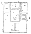
- Figure 1 is a plan view of a storage system that utilises the apparatus for retrieving data according to one embodiment of the invention;
- Figure 2 is a perspective view of a cartridge access device associated with the data storage system with a side member removed to show a reader attached to a moveable cartridge plunge mechanism mounted within the cartridge access device;
- Figure 3 is a simplified cross-sectional view of the cartridge access device with the cartridge plunge mechanism shown in the extended position so that the reader is positioned in close proximity to a transponder mounted to a data cartridge contained in the media storage system;
- Figure 4 is a plan view of the reader; and
- Figure 5 is a plan view of the transponder.
-
-
Apparatus 10 for retrieving data related to adata cartridge 20 is shown and described herein as it could be used with a data ormedia storage system 15. Briefly,media storage systems 15 are used to store large volumes of computer readable data. The computer readable data is typically stored onmultiple data cartridges 20 that are arranged in themedia storage system 15 oncartridge storage racks 30. It is therefore desirable to identifyindividual data cartridges 20 and the data stored thereon with as much information that is possible without having physically to remove thedata cartridge 20 from thecartridge storage rack 30. The described system provides a method and apparatus for reading data related to thedata cartridge 20. - The
media storage system 15 may include acartridge access device 40. Thecartridge access device 40 can be moved among thecartridge storage racks 30 and positioned adjacent adata cartridge 20 to access thedata cartridges 20 stored therein. Areader 140 is mounted to thecartridge access device 40 and data related to the data cartridge 20 (for example, cartridge ID, user, data origin, date, data format, load count, and so on) is stored in atransponder 150 mounted thereon. As such, the related data can be read from eachdata cartridge 20 as thecartridge access device 40 is moved among thestorage racks 30 and each cartridge stored therein can be automatically inventoried. That is, where a user makes a request to inventory thedata cartridges 20 stored in themedia storage system 15, the related data (for example, cartridge ID, data format, date, and so on) can be read from eachdata cartridge 20 as thecartridge access device 40 is moved among thestorage racks 30 and the related data displayed or stored in a database for later use. Thus, when a request is made to read and/or write data to adata cartridge 20, the requesteddata cartridge 20 is readily recognised, removed from thestorage rack 30, and delivered to the read/writedevice 60 for access to the computer readable data stored thereon. Likewise, where adata cartridge 20 is placed in a mail slot (that is, a drop-off point, not shown) in themedia storage system 15, the related data is read to identify thedata cartridge 20 so that thedata cartridge 20 is returned or entered at the appropriate position in thestorage rack 30. Furthermore, the user may search for adata cartridge 20 as thecartridge access device 40 is moved among thestorage racks 30 and the related data is read from thedata cartridge 20 and transmitted to the user. - The method preferably includes positioning the
cartridge access device 40, and hence thereader 140, adjacent thedata cartridge 20 and activating thetransponder 150. The activatedtransponder 150 transmits a data signal containing the data related to thedata cartridge 20, which is received at the reader and processed by thecontroller 147. For example, the related data may be displayed for a user browsing themedia storage system 15, used to create an inventory for immediate or later use, used to identify a requesteddata cartridge 20, and so on. - It is important to recognise that the
data cartridges 20 may be closely packed in thestorage rack 30. Therefore, the likelihood exists for interference withtransponders 150 onnearby data cartridges 20. The system addresses this concern by preferably mounting thereader 140 to acartridge plunge mechanism 90 movable between extended and retracted positions within thecartridge access device 40. Thus, thereader 140 can be extended toward thedata cartridge 20 or retracted therefrom for more accurate positioning. In addition, mounting thereader 140 to the movablecartridge plunge mechanism 90 allows thereader 140 to be positioned near thedata cartridge 20 without thereader 140 physically contacting thetransponder 150. As such, thereader 140 and thetransponder 150 are protected against physical wear. - It is also important to recognise that the mechanical tolerances (that is, the distance between the
data cartridge 20 and the cartridge access device 40) may vary from onemedia storage system 15 to another. Indeed, the mechanical tolerances may vary within a singlemedia storage system 15 between onestorage rack 30 and another or even between onedata cartridge 20 and another. Therefore, inmedia storage systems 15 where mechanical tolerances vary, thereader 140 may not be sufficiently close to thetransponder 150 in some instances. The system addresses this concern by individually adjusting the position of thereader 140 at eachdata cartridge 20 using thecartridge plunge mechanism 90. That is, thecartridge plunge mechanism 90, and hence thereader 140 mounted thereto, can be extended or retracted to maintain the desired distance between thereader 140 and thetransponder 150 at eachdata cartridge 20, regardless of the variability in the mechanical tolerances of themedia storage system 15. - Having generally described methods and apparatus for retrieving data related to a
data cartridge 20 in amedia storage system 15 and several advantages thereof, the methods and apparatus will now be described in further detail. - The
apparatus 10 for reading data related to thedata cartridges 20 may comprise amedia storage system 15 such as that shown in Figure 1. Themedia storage system 15 includesdata cartridges 20 stored in one or more storage racks 30. In use, a control system (not shown) moves acartridge access device 40 along apositioning rail 50 adjacent thedata cartridges 20. Hence, data related to adata cartridge 20 can be read (that is, using standard protocols) when thecartridge access device 40 is positioned adjacent thedata cartridge 20. For purposes of illustration, thecartridge access device 40 is shown inpositions cartridge access device 40 is shown adjacent thedata cartridge 20 contained in thestorage rack 30 atpositions write device 60 atposition 42. - In use, a computer (not shown) linked to the media storage system 15 (for example, via a direct connection, remote connection, network connection, and so on) may issue a request to access a
data cartridge 20 or to inventory thedata cartridges 20 stored in themedia storage system 15. In response, the control system moves thecartridge access device 40 along thepositioning rail 50 adjacent thedata cartridges 20. Where access to adata cartridge 20 is requested, the control system positions thecartridge access device 40 adjacent the requesteddata cartridge 20, and signals thecartridge access device 40 to withdraw thedata cartridge 20 from thestorage rack 30 and to carry it to the read/write device 60 where the linked computer can access the computer readable data stored thereon. The requesteddata cartridge 20 can be readily identified from the data related to thedata cartridge 20 and read at thecartridge access device 40, as explained in more detail below. Where thedata cartridges 20 are to be inventoried, the related data is read from eachdata cartridge 20 as theaccess device 40 is moved about themedia storage device 15. It is understood that the system can provide both reading the related data from eachdata cartridge 20 by stopping thecartridge access device 40 adjacent eachdata cartridge 20 and/or "on the fly" as thecartridge access device 40 is moving along thepositioning rail 50. - The
cartridge access device 40 shown in Figure 2 may include aframe assembly 70 that defines a chamber orcavity 80 sized to receive thedata cartridge 20 therein (for example, for carrying it to the read/write device 60). Acartridge plunge mechanism 90 is slidably mounted to theframe assembly 70 so that thecartridge plunge mechanism 90 may be moved toward (that is, extended) and away (that is, retracted) from the cartridge access end 75 of theframe assembly 70, generally in the directions indicated byarrows reader 140 can be mounted to thecartridge plunge mechanism 90 and thus be further positioned near thedata cartridge 20 by moving thecartridge plunge mechanism 90 between the extended and retracted positions. Thecartridge plunge mechanism 90 may also be provided with afinger assembly 100 configured to engage thedata cartridge 20. Thefinger assembly 100 allows thecartridge plunge mechanism 90 to engage and withdraw thedata cartridge 20 from thestorage rack 30 and the read/write device 60 when so requested. - An optional encoder system (not shown) may provide an output signal from which information may be derived about the position of the
cartridge plunge mechanism 90 within the frame assembly 70 (for example, along the path indicated byarrows 93, 97). The encoder system can thus be used to determine the position of thereader 140 on thecartridge plunge mechanism 90 for positioning thereader 140 adjacent thedata cartridge 20. In one embodiment, the encoder system may include an elongate linear reference member having a plurality of index marks thereon. A detector assembly (not shown) mounted to thecartridge plunge mechanism 90 detects the index marks on the elongate linear reference member and produces an output signal indicative of the presence or absence of an index mark. A picker control system (not shown) connected to the detector assembly may derive information relating to the position, velocity, and acceleration of thecartridge plunge mechanism 90 based on the output signal produced by the detector assembly. The picker control system may use such information to control the operation and movement of thecartridge plunge mechanism 90 in the directions ofarrows - A
reader 140 is mounted to thecartridge access device 40, preferably on athumb portion 130 of thecartridge plunge mechanism 90, as shown in Figure 2 and Figure 3. In addition, atransponder 150 containing data related to thecartridge 20 is mounted to eachcartridge 20 in themedia storage system 15, as shown in Figure 3. In use, thecartridge access device 40 is positioned adjacent the cartridge 20 (for example, as inposition reader 140 is within the transmission range 160 (Figure 3) of the transponder 150 (for example, forming an air interface therebetween). Once thereader 140 is within thetransmission range 160 of thetransponder 150, thereader 140 activates thetransponder 150 and triggers a response (that is, a data signal containing the related data) from thetransponder 150, as described in more detail below. - The
reader 140 is preferably mounted or attached to thethumb portion 130 of thecartridge plunge mechanism 90 50 that thereader 140 can be extended toward thedata cartridge 20 or retracted therefrom by moving thecartridge plunge mechanism 90 generally in the directions ofarrows reader 140 can be positioned close to thetransponder 150, preferably within about three millimetres of one another. As an example, where thereader 140 is mounted to the cartridge access end 75 of theframe assembly 70, thereader 140 may receive a signal not only from the querieddata cartridge 20, but also from thetransponders 150 on othernearby data cartridges 20. Where, however, thereader 140 is mounted to thecartridge plunge mechanism 90, thereader 140 can be positioned immediately adjacent to the queried transponder 150 (as shown in Figure 3), thus reducing the likelihood thattransponders 150 on othernearby data cartridges 20 detect the query. - In addition, mounting the
reader 140 to thecartridge plunge mechanism 90 also permits thereader 140 to be adjusted at eachdata cartridge 20 to be within the requiredtransmission range 160 of thetransponder 150 regardless of the variability in the mechanical tolerances of themedia storage system 15. As an example, where thecartridge access device 40 is twenty millimetres from anadjacent data cartridge 20, thecartridge plunge mechanism 90 is extended beyond the cartridge access end 75 of theframe assembly 70 about seventeen millimetres, thus defining atransmission range 160 of about three millimetres. When thecartridge access device 40 is then moved adjacent anotherdata cartridge 20 stored in themedia storage system 15 where the cartridge access device is now twenty-five millimetres from thedata cartridge 20, the cartridge plunge mechanism is extended beyond the cartridge access end 75 of theframe assembly 70 about twenty-two millimetres, once again defining atransmission range 160 of about three millimetres. - It is understood, however, that the
transponder 150 and/or thereader 140 can be embedded in thedata cartridge 20 and thecartridge plunge mechanism 90, respectively, or attached using any other suitable means (for example, adhesive, integrally formed therein, and so on). - The
preferred transmission range 160 of about three millimetres also serves to reduce or eliminate physical wear that may occur were thereader 140 and thetransponder 150 to be in repeated contact with one another. However, the invention is not to be limited to thepreferred transmission range 160 of three millimetres. In other embodiments, thereader 140 can come into contact with thetransponder 150. Likewise, thetransmission range 160 can be greater than three millimetres. Thetransmission range 160 may vary and may depend on design considerations such as the transmission and receiving capabilities of thereader 140 and thetransponder 150, the likelihood of interference or cross-talk, and so on. Other design considerations may include the respective power requirements of thereader 140 and thetransponder 150, the signal detection capability of thereader 140, the transmission frequencies, the rate of transmission, and so on. - The
exemplary reader 140 shown in Figure 4 includes an antenna 143 (for example, numerous turns of a fine wire to form a coil) etched on a flexible printedcircuit substrate 145. Thereader 140 is operatively associated with acontroller 147. That is, thecontroller 147 is linked (via a direct or remote connection) with thereader 140 for communicating therebetween, For example, where thereader 140 is an inductive reader, thecontroller 147 may cause an electrical current to pass through theantenna 143, thus generating an energy field for activating thetransponder 150. Once thetransponder 150 is activated, the controller may transmit an interrogation signal through theantenna 143 querying thetransponder 150. Likewise, when thereader 140 receives a response or a data signal from thetransponder 150, the data signal is delivered to thecontroller 147 for further processing. For example, the controller may convert the data signal into user-readable data for output at a computer, generate or update an inventory database with the data relating to thedata cartridge 20 contained in the data signal, and so on Although thecontroller 147 is shown separate from thecircuit board 145, thereader 140 and thecontroller 147 can be fabricated together on a single circuit board (for example, as an integrated circuit). - It is understood that the
controller 147 and thereader 140 include any required circuitry and software or firmware for performing the functions described herein. The design of such controllers and readers is well known in the art. In addition, thecontroller 147 and thereader 140 can be used to perform any suitable functions, such as but not limited to, signal conditioning, parity error checking, correction, and so on. Likewise, once the data signal is correctly received at thereader 140 from thetransponder 150 and decoded at thecontroller 147, thecontroller 147 may instruct thetransponder 150, through thereader 140, to cease transmitting. Where thetransponder 150 is programmable, thecontroller 147 andreader 140 can also include circuitry to perform the necessary data modulation/demodulation and data transfer. - The
exemplary transponder 150 shown in Figure 5 preferably includes a low powered integrated circuit (IC) 157 and an antenna 153 (for example, numerous turns of a fine wire to form a coil) etched on a flexible printedcircuit substrate 155. TheIC 157 preferably includes a processor (or processing logic) and at least one memory. The processor receives the query signal from thereader 140 at theantenna 153. The processor retrieves data stored on the memory and generates a response or data signal containing the data requested by the query. The data signal is transmitted via theantenna 153 on the transponder 150 (for example, via radio frequency) and received at theantenna 143 on thereader 140. While thetransponder 150 is shown fabricated as a single printed circuit board, the transponder can comprise separate components linked to one another. - The
transponder 150 can include any suitable memory. The memory may include Read Only Memory (ROM) for security data and operating system instructions, which in conjunction with the processor, controls internal functions (for example, response delay timing, data flow control, and power supply switching). The memory may also include Random Access Memory (RAM) to facilitate temporary data storage during query and response. The memory may also include non-volatile programmable memory (for example, Electrically Erasable Programmable Read Only Memory or EEPROM) to store data related to thedata cartridge 20 that is retained therein when thetransponder 150 is deactivated or in a power-saving mode. The memory may also include write-once/read many (WORM) memory, wherein thereader 140 and/orcontroller 147 could be configured (or a separate writing device provided) to write data to the transponder 150 (for example, an indication of when or how often thedata cartridge 20 is accessed). Likewise, data buffers may be used to hold temporarily incoming data following demodulation and outgoing data for modulation and interface with thereader 140. In addition, data stored in memory on thetransponder 150 can be conventionally organised using data identifiers and error detection bits (that is, source encoding). - The
transponder 150 preferably stores up to four kilobytes of data related to thedata cartridge 20. In one embodiment, the related data can be partitioned. For example, the related data may include device common information (for example, remaining capacity, maximum capacity, tape alert flags, and so on), medium common attributes (for example, manufacturer, serial number, and so on), and host common attributes (for example, vendor, version, date last written, and so on). Likewise, the transponder may include permanent data and rewritable data. However, it is understood that the quantity of data stored on thetransponder 150 can vary depending on the design characteristics of thetransponder 150, the type of data stored thereon, and so on It is also understood that the type of data that is stored on thetransponder 150 is immaterial to the scope of the present invention. For example, a user identification or pass code can be stored on thetransponder 150 and suitable software can be provided to manage access to thedata cartridge 20 based on the user identification and/or pass code. Such software can be readily developed by one skilled in the art. - The
reader 140 and thetransponder 150 preferably use radio frequency identification (RFID) technology. Generally, RFID transponders have small power requirements (for example, in the microwatt to milliwatt range), and can be passive, active, or a combination thereof. That is, a passive RFID transponder derives power from a magnetic or electric field generated by the reader, while an active RFID transponder is self-powered by an internal battery. A combination passive/active RFID transponder is powered by an internal battery, but only draws power from the battery after being passed through a high energy activation field. RFID technology is well understood in the art. However, it is understood that thereader 140 and thetransponder 150 are not limited to RFID technology and can include other storage and communication systems now known or later developed for storing and reading data related to thedata cartridge 20. - It should be noted that although the preferred embodiment is illustrated using a particular
media storage system 15, the teachings herein may be utilised in any of a wide range of media storage systems now known in the art or that may be developed in the future for accessing or taking inventory of one ormore data cartridges 20. Accordingly, the present invention should not be regarded as limited to the particularmedia storage system 15 shown and described herein. - It should also be noted that while the
cartridge access device 40 is shown and described herein as it could be used to store and retrieve a linear tape open (LTO)data cartridge 20 having a standard size and configuration, it is not limited to any particular type or style of data cartridge. Indeed, thecartridge access device 40 could be used with any type of media storage system comprising any type of storage medium (for example, magnetic disk or tape, optical disk, and so on). Consequently, the present invention should not be regarded as limited to use with themedia storage system 15 for theLTO data cartridge 20 shown and described herein. - The disclosures in United States patent application no. 09/754,955, from which this application claims priority, and in the abstract accompanying this application are incorporated herein by reference.
Claims (10)
- Apparatus for retrieving data related to a data cartridge contained in a media storage system, including:a cartridge access device (40) operatively associated with the media storage system, said cartridge access device being operable to retrieve and transport the data cartridge within the media storage system;a transponder (150) mounted to said data cartridge, said transponder being operable to transmit a data signal containing said data related to the data cartridge;a reader (140) mounted to said cartridge access device, said reader being operable to receive said transmitted data signal from said transponder; anda controller (147) operatively associated with said reader, said controller in use operating said reader to activate and query said transponder to transmit said data signal, said control system being responsive to said transmitted data signal.
- Apparatus as in claim 1, wherein said cartridge access device (40) includes a cartridge plunge mechanism (90) moveable between a retracted position and an extended position and wherein said reader (140) is mounted to said cartridge plunge mechanism.
- Apparatus as in claim 2, wherein said cartridge plunge mechanism (40) includes a thumb portion (130), said reader (140) being attached to said thumb portion.
- Apparatus as in any preceding claim, wherein said controller (147) is designed to operate said reader (140) to activate and query said transponder (1500 when said cartridge access device (40) is positioned adjacent the data cartridge (20) to be queried.
- Apparatus as in any preceding claim, wherein said transponder (150) is a radio frequency identification (RFID) transponder.
- A method of retrieving data related to a data cartridge in a media storage system, including the steps of:positioning a cartridge access device (40) adjacent said data cartridge;transmitting a data signal containing said data related to the data cartridge from a transponder (150) attached to said data cartridge; andreceiving said transmitted data signal at a reader (140) attached to said cartridge access device.
- A method as in claim 6, including the step of writing at least a portion of said data related to the data cartridge to said transponder (150).
- A method as in claim 6 or 7, including the step of activating said transponder (150).
- A method as in claim 6, 7 or 8, including the step of querying said transponder (150) to transmit said data.
- A method as in any one of claims 6 to 9, including the step of processing said transmitted data signal at a controller (147) operatively associated with said reader (140).
Applications Claiming Priority (2)
| Application Number | Priority Date | Filing Date | Title |
|---|---|---|---|
| US754955 | 1985-07-15 | ||
| US09/754,955 US6870797B2 (en) | 2001-01-04 | 2001-01-04 | Media storage system using a transponder for transmitting data signal |
Publications (3)
| Publication Number | Publication Date |
|---|---|
| EP1225577A2 true EP1225577A2 (en) | 2002-07-24 |
| EP1225577A3 EP1225577A3 (en) | 2002-08-07 |
| EP1225577B1 EP1225577B1 (en) | 2004-11-03 |
Family
ID=25037098
Family Applications (1)
| Application Number | Title | Priority Date | Filing Date |
|---|---|---|---|
| EP01306367A Expired - Lifetime EP1225577B1 (en) | 2001-01-04 | 2001-07-25 | Apparatus and method for retrieving data related to a data cartridge |
Country Status (4)
| Country | Link |
|---|---|
| US (3) | US6870797B2 (en) |
| EP (1) | EP1225577B1 (en) |
| JP (1) | JP2002230873A (en) |
| DE (1) | DE60106858T2 (en) |
Cited By (3)
| Publication number | Priority date | Publication date | Assignee | Title |
|---|---|---|---|---|
| US7660812B2 (en) | 2005-09-02 | 2010-02-09 | Imation Corp. | Tracking physical inventory of data storage media |
| US7953433B2 (en) | 2007-04-24 | 2011-05-31 | Imation Corp. | Data storage device and data storage device tracing system |
| US8131421B2 (en) | 2007-05-29 | 2012-03-06 | Fujifilm Recording Media U.S.A., Inc. | System and method for tracking media |
Families Citing this family (101)
| Publication number | Priority date | Publication date | Assignee | Title |
|---|---|---|---|---|
| US6870797B2 (en) * | 2001-01-04 | 2005-03-22 | Hewlett-Packard Development Company, L.P. | Media storage system using a transponder for transmitting data signal |
| US6968463B2 (en) | 2001-01-17 | 2005-11-22 | Hewlett-Packard Development Company, L.P. | System for controlling access to resources in a storage area network |
| ATE368351T1 (en) | 2001-05-14 | 2007-08-15 | Innovision Res & Tech Plc | PORTABLE COMMUNICATIONS DEVICE FOR USE IN A SALES SYSTEM |
| US6915397B2 (en) | 2001-06-01 | 2005-07-05 | Hewlett-Packard Development Company, L.P. | System and method for generating point in time storage copy |
| JP2003006963A (en) * | 2001-06-26 | 2003-01-10 | Sony Corp | Recording/reproducing device |
| US6931487B2 (en) * | 2001-10-22 | 2005-08-16 | Hewlett-Packard Development Company L.P. | High performance multi-controller processing |
| US7032131B2 (en) | 2002-03-26 | 2006-04-18 | Hewlett-Packard Development Company, L.P. | System and method for ensuring merge completion in a storage area network |
| US7007042B2 (en) | 2002-03-28 | 2006-02-28 | Hewlett-Packard Development Company, L.P. | System and method for automatic site failover in a storage area network |
| US6924777B2 (en) * | 2003-03-17 | 2005-08-02 | Hewlett-Packard Development Company, L.P. | Enhanced antenna using flexible circuitry |
| CA2430242A1 (en) * | 2003-06-06 | 2004-12-06 | Kimihiko Ernst Sato | Large array of radio frequency id transponders deployed in an array by use of deploying rows of transponders that unwind from long spools of high strength fiber or tape with passive rfid transponders separated by fixed lengths |
| US9646451B2 (en) * | 2003-06-11 | 2017-05-09 | Ncr Corporation | Automated business system and method of vending and returning a consumer product |
| US20050036408A1 (en) * | 2003-08-15 | 2005-02-17 | Quantum Corporation | Automated storage library cartridge gripper with cartridge detector |
| JP4040564B2 (en) * | 2003-10-14 | 2008-01-30 | キヤノン株式会社 | Disk-shaped recording medium alignment device |
| KR100571964B1 (en) * | 2004-02-28 | 2006-04-17 | 삼성전자주식회사 | Image forming apparatus |
| TWI290272B (en) * | 2004-03-12 | 2007-11-21 | Murata Machinery Ltd | Moving body system |
| KR20050104652A (en) * | 2004-04-29 | 2005-11-03 | 삼성에스디아이 주식회사 | Electron emission display device and driving method thereof |
| US7333293B2 (en) * | 2004-06-29 | 2008-02-19 | Hewlett-Packard Development Company, L.P. | Storage system having a reader with a light sensing portion inclined with respect to an axis of a label of a storage medium |
| JP2006082397A (en) * | 2004-09-16 | 2006-03-30 | Fuji Photo Film Co Ltd | Printer, image output device, and method for guiding insertion port of recording medium |
| US7307924B2 (en) * | 2004-10-27 | 2007-12-11 | Hewlett-Packard Development Company, L.P. | Systems and methods for cartridge identification |
| US7551081B2 (en) * | 2004-11-10 | 2009-06-23 | Rockwell Automation Technologies, Inc. | Systems and methods that integrate radio frequency identification (RFID) technology with agent-based control systems |
| US7339476B2 (en) * | 2004-11-10 | 2008-03-04 | Rockwell Automation Technologies, Inc. | Systems and methods that integrate radio frequency identification (RFID) technology with industrial controllers |
| US8127088B2 (en) | 2005-01-27 | 2012-02-28 | Hewlett-Packard Development Company, L.P. | Intelligent cache management |
| US7301718B2 (en) | 2005-01-31 | 2007-11-27 | Hewlett-Packard Development Company, L.P. | Recording errors in tape drives |
| US7530515B2 (en) * | 2005-02-15 | 2009-05-12 | Imation Corp. | Data storage tape cartridge and system having a radio frequency write medium |
| WO2006105582A1 (en) * | 2005-04-06 | 2006-10-12 | Opdicom Pty Ltd | Disc storage device and optical disc |
| US7916615B2 (en) | 2005-06-09 | 2011-03-29 | The Invention Science Fund I, Llc | Method and system for rotational control of data storage devices |
| US8159925B2 (en) | 2005-08-05 | 2012-04-17 | The Invention Science Fund I, Llc | Limited use memory device with associated information |
| US7512959B2 (en) | 2005-05-09 | 2009-03-31 | Searete Llc | Rotation responsive disk activation and deactivation mechanisms |
| US7916592B2 (en) | 2005-05-09 | 2011-03-29 | The Invention Science Fund I, Llc | Fluid mediated disk activation and deactivation mechanisms |
| US7748012B2 (en) | 2005-05-09 | 2010-06-29 | Searete Llc | Method of manufacturing a limited use data storing device |
| US8099608B2 (en) | 2005-05-09 | 2012-01-17 | The Invention Science Fund I, Llc | Limited use data storing device |
| US7668068B2 (en) | 2005-06-09 | 2010-02-23 | Searete Llc | Rotation responsive disk activation and deactivation mechanisms |
| KR101381331B1 (en) | 2005-05-09 | 2014-04-04 | 테라노스, 인코포레이티드 | Point-of-care fluidic systems and uses thereof |
| US8121016B2 (en) | 2005-05-09 | 2012-02-21 | The Invention Science Fund I, Llc | Rotation responsive disk activation and deactivation mechanisms |
| US7770028B2 (en) * | 2005-09-09 | 2010-08-03 | Invention Science Fund 1, Llc | Limited use data storing device |
| US7694316B2 (en) | 2005-05-09 | 2010-04-06 | The Invention Science Fund I, Llc | Fluid mediated disk activation and deactivation mechanisms |
| US8220014B2 (en) | 2005-05-09 | 2012-07-10 | The Invention Science Fund I, Llc | Modifiable memory devices having limited expected lifetime |
| US7907486B2 (en) | 2006-06-20 | 2011-03-15 | The Invention Science Fund I, Llc | Rotation responsive disk activation and deactivation mechanisms |
| US7596073B2 (en) | 2005-05-09 | 2009-09-29 | Searete Llc | Method and system for fluid mediated disk activation and deactivation |
| US9396752B2 (en) | 2005-08-05 | 2016-07-19 | Searete Llc | Memory device activation and deactivation |
| US7519980B2 (en) | 2005-05-09 | 2009-04-14 | Searete Llc | Fluid mediated disk activation and deactivation mechanisms |
| US7565596B2 (en) | 2005-09-09 | 2009-07-21 | Searete Llc | Data recovery systems |
| US8462605B2 (en) | 2005-05-09 | 2013-06-11 | The Invention Science Fund I, Llc | Method of manufacturing a limited use data storing device |
| US8218262B2 (en) | 2005-05-09 | 2012-07-10 | The Invention Science Fund I, Llc | Method of manufacturing a limited use data storing device including structured data and primary and secondary read-support information |
| US8140745B2 (en) | 2005-09-09 | 2012-03-20 | The Invention Science Fund I, Llc | Data retrieval methods |
| US7668069B2 (en) | 2005-05-09 | 2010-02-23 | Searete Llc | Limited use memory device with associated information |
| US7616117B2 (en) * | 2005-07-19 | 2009-11-10 | Rockwell Automation Technologies, Inc. | Reconciliation mechanism using RFID and sensors |
| US7388491B2 (en) | 2005-07-20 | 2008-06-17 | Rockwell Automation Technologies, Inc. | Mobile RFID reader with integrated location awareness for material tracking and management |
| US7779218B2 (en) * | 2005-07-22 | 2010-08-17 | Hewlett-Packard Development Company, L.P. | Data synchronization management |
| US7764191B2 (en) * | 2005-07-26 | 2010-07-27 | Rockwell Automation Technologies, Inc. | RFID tag data affecting automation controller with internal database |
| US7206156B2 (en) | 2005-07-27 | 2007-04-17 | Hewlett-Packard Development Company, L.P. | Tape drive error management |
| US8260948B2 (en) * | 2005-08-10 | 2012-09-04 | Rockwell Automation Technologies, Inc. | Enhanced controller utilizing RFID technology |
| US8311663B2 (en) | 2005-08-31 | 2012-11-13 | International Business Machines Corporation | Apparatus and method to store information |
| US20070052540A1 (en) * | 2005-09-06 | 2007-03-08 | Rockwell Automation Technologies, Inc. | Sensor fusion for RFID accuracy |
| US7510110B2 (en) | 2005-09-08 | 2009-03-31 | Rockwell Automation Technologies, Inc. | RFID architecture in an industrial controller environment |
| US7931197B2 (en) * | 2005-09-20 | 2011-04-26 | Rockwell Automation Technologies, Inc. | RFID-based product manufacturing and lifecycle management |
| US7446662B1 (en) | 2005-09-26 | 2008-11-04 | Rockwell Automation Technologies, Inc. | Intelligent RFID tag for magnetic field mapping |
| US20070075832A1 (en) * | 2005-09-30 | 2007-04-05 | Rockwell Automation Technologies, Inc. | RFID reader with programmable I/O control |
| US8025227B2 (en) * | 2005-09-30 | 2011-09-27 | Rockwell Automation Technologies, Inc. | Access to distributed databases via pointer stored in RFID tag |
| US7325078B2 (en) | 2005-10-06 | 2008-01-29 | Hewlett-Packard Development Company, L.P. | Secure data scrubbing |
| US7721053B2 (en) | 2005-10-24 | 2010-05-18 | Hewlett-Packard Development Company, L.P. | Intelligent logical unit provisioning |
| US7436615B2 (en) * | 2005-12-08 | 2008-10-14 | International Business Machines Corporation | Using a measured error to determine coefficients to provide to an equalizer to use to equalize an input signal |
| US7642907B2 (en) * | 2005-12-21 | 2010-01-05 | Lear Corporation | Wireless buckle-up detection using RF technology |
| US20070180207A1 (en) * | 2006-01-18 | 2007-08-02 | International Business Machines Corporation | Secure RFID backup/restore for computing/pervasive devices |
| US11287421B2 (en) | 2006-03-24 | 2022-03-29 | Labrador Diagnostics Llc | Systems and methods of sample processing and fluid control in a fluidic system |
| US8741230B2 (en) | 2006-03-24 | 2014-06-03 | Theranos, Inc. | Systems and methods of sample processing and fluid control in a fluidic system |
| US7467268B2 (en) | 2006-04-14 | 2008-12-16 | Hewlett-Packard Development Company, L.P. | Concurrent data restore and background copy operations in storage networks |
| BRPI0710289A2 (en) * | 2006-04-24 | 2011-08-09 | Richard Fuisz | body fluid analyzer, body inclusion system and method for programming |
| US8007999B2 (en) | 2006-05-10 | 2011-08-30 | Theranos, Inc. | Real-time detection of influenza virus |
| US8264928B2 (en) | 2006-06-19 | 2012-09-11 | The Invention Science Fund I, Llc | Method and system for fluid mediated disk activation and deactivation |
| US8432777B2 (en) * | 2006-06-19 | 2013-04-30 | The Invention Science Fund I, Llc | Method and system for fluid mediated disk activation and deactivation |
| US7784690B1 (en) * | 2006-08-31 | 2010-08-31 | Symantec Operating Corporation | Mobile device application for managing media and media devices |
| US20080061979A1 (en) * | 2006-09-13 | 2008-03-13 | Hause Curtis B | Traceable RFID enable data storage device |
| US20080122623A1 (en) * | 2006-09-13 | 2008-05-29 | Hause Curtis B | System and method for tracing data storage devices |
| US20080065676A1 (en) * | 2006-09-13 | 2008-03-13 | Hause Curtis B | System and method for tracing data storage devices |
| EP2062138A2 (en) * | 2006-09-13 | 2009-05-27 | Imation Corp. | System and method for tracing data storage devices |
| US20080113391A1 (en) | 2006-11-14 | 2008-05-15 | Ian Gibbons | Detection and quantification of analytes in bodily fluids |
| US8131263B2 (en) * | 2006-12-06 | 2012-03-06 | Microsoft Corporation | Backup media with wireless identifications tags |
| US7934027B2 (en) | 2007-01-19 | 2011-04-26 | Hewlett-Packard Development Company, L.P. | Critical resource management |
| US20080186187A1 (en) * | 2007-02-06 | 2008-08-07 | Christopher Alan Adkins | Ink tank having integrated rfid tag |
| US20080198022A1 (en) * | 2007-02-21 | 2008-08-21 | Imation Corp. | Inkjet printable RFID label and method of printing an inkjet printable RFID label |
| US7861031B2 (en) | 2007-03-01 | 2010-12-28 | Hewlett-Packard Development Company, L.P. | Access control management |
| US8024514B2 (en) | 2007-03-01 | 2011-09-20 | Hewlett-Packard Development Company, L.P. | Access control management |
| US7694079B2 (en) | 2007-04-04 | 2010-04-06 | Hewlett-Packard Development Company, L.P. | Tagged sequential read operations |
| US8337133B2 (en) | 2007-06-25 | 2012-12-25 | International Business Machines Corporation | Segregating wafer carrier types in semiconductor storage devices |
| CN103323610B (en) | 2007-10-02 | 2016-12-28 | 赛拉诺斯股份有限公司 | Modular point-of-care devices and application thereof |
| US8016194B2 (en) | 2008-03-06 | 2011-09-13 | Imation Corp. | Mobile data storage device reader having both radiofrequency and barcode scanners |
| US8862448B2 (en) | 2009-10-19 | 2014-10-14 | Theranos, Inc. | Integrated health data capture and analysis system |
| CN106323876B (en) | 2011-01-21 | 2020-02-14 | 西拉诺斯知识产权有限责任公司 | System and method for maximizing sample usage |
| US9632102B2 (en) | 2011-09-25 | 2017-04-25 | Theranos, Inc. | Systems and methods for multi-purpose analysis |
| US9619627B2 (en) | 2011-09-25 | 2017-04-11 | Theranos, Inc. | Systems and methods for collecting and transmitting assay results |
| US9664702B2 (en) | 2011-09-25 | 2017-05-30 | Theranos, Inc. | Fluid handling apparatus and configurations |
| US20140170735A1 (en) | 2011-09-25 | 2014-06-19 | Elizabeth A. Holmes | Systems and methods for multi-analysis |
| US9268915B2 (en) | 2011-09-25 | 2016-02-23 | Theranos, Inc. | Systems and methods for diagnosis or treatment |
| US8475739B2 (en) | 2011-09-25 | 2013-07-02 | Theranos, Inc. | Systems and methods for fluid handling |
| US8840838B2 (en) | 2011-09-25 | 2014-09-23 | Theranos, Inc. | Centrifuge configurations |
| US9250229B2 (en) | 2011-09-25 | 2016-02-02 | Theranos, Inc. | Systems and methods for multi-analysis |
| US9810704B2 (en) | 2013-02-18 | 2017-11-07 | Theranos, Inc. | Systems and methods for multi-analysis |
| US10012664B2 (en) | 2011-09-25 | 2018-07-03 | Theranos Ip Company, Llc | Systems and methods for fluid and component handling |
| JP2016110686A (en) * | 2014-12-02 | 2016-06-20 | パナソニックIpマネジメント株式会社 | Optical disc library device, optical disc, and optical disc library system |
| US9666223B2 (en) * | 2015-10-02 | 2017-05-30 | International Business Machines Corporation | Enhanced tape library cataloging |
Citations (2)
| Publication number | Priority date | Publication date | Assignee | Title |
|---|---|---|---|---|
| US5870245A (en) * | 1995-11-09 | 1999-02-09 | Overland Data, Inc. | Modular cabinet for data storage media and drives |
| EP1039410A1 (en) * | 1999-03-24 | 2000-09-27 | Hewlett-Packard Company | Intelligent media reader and label printer |
Family Cites Families (27)
| Publication number | Priority date | Publication date | Assignee | Title |
|---|---|---|---|---|
| US4839875A (en) * | 1986-05-19 | 1989-06-13 | Anritsu Corporation | Technique for automatic tracking of cassette rentals and managing of information related thereto |
| US5034904A (en) | 1988-01-27 | 1991-07-23 | Storage Technology Corporation | Vision system illumination calibration apparatus |
| US5880443A (en) * | 1990-01-24 | 1999-03-09 | Automated Healthcare | Automated system for selecting packages from a cylindrical storage area |
| JPH04157690A (en) | 1990-10-19 | 1992-05-29 | Victor Co Of Japan Ltd | Multiple loading cassette recording/reproduction device |
| JPH05128675A (en) * | 1991-11-05 | 1993-05-25 | Sony Corp | Automatic cassette changer |
| US5303214A (en) * | 1992-01-03 | 1994-04-12 | International Business Machines Corporation | Multi-media-type automatic libraries |
| JPH0652657A (en) | 1992-07-30 | 1994-02-25 | Hitachi Electron Eng Co Ltd | Bar code reading system of magnetic tape |
| US5455409A (en) * | 1993-08-16 | 1995-10-03 | Texas Digital Systems, Inc. | Apparatus and method for monitoring a plurality of coded articles and for identifying the location of selected articles |
| JPH07210971A (en) | 1994-01-20 | 1995-08-11 | Hitachi Electron Eng Co Ltd | Recording medium cartridge library device |
| US5729464A (en) * | 1995-09-29 | 1998-03-17 | International Business Machines Corporation | Media identification in an automated data library |
| US5971281A (en) * | 1996-08-26 | 1999-10-26 | Storage Technology Corporation | Method for storing multiple logical data volumes on a single physical volume utilizing writable labels and physical volume produced thereby |
| JPH10228753A (en) * | 1996-12-13 | 1998-08-25 | Sony Corp | Recording medium cartridge, recording/reproducing device using the same and information management device |
| US5963134A (en) * | 1997-07-24 | 1999-10-05 | Checkpoint Systems, Inc. | Inventory system using articles with RFID tags |
| US6100788A (en) * | 1997-12-29 | 2000-08-08 | Storage Technology Corporation | Multifunctional electromagnetic transponder device and method for performing same |
| US6160786A (en) | 1998-03-20 | 2000-12-12 | Hewlett-Packard Company | Cartridge engaging assembly with rack drive thumb actuator system |
| US6262863B1 (en) * | 1998-07-01 | 2001-07-17 | Storage Technology Corporation | Automated storage library with rail mechanism providing flexible robot access |
| US6138909A (en) * | 1998-07-22 | 2000-10-31 | Advanced Digital Information Corporation | Media handling system and method |
| US6231391B1 (en) * | 1999-08-12 | 2001-05-15 | Robinson Nugent, Inc. | Connector apparatus |
| US6175539B1 (en) | 1998-08-28 | 2001-01-16 | Hewlett-Packard Co. | System and method for providing wireless control signals to cartridge access device in a cartridge storage system |
| US6201474B1 (en) * | 1998-10-21 | 2001-03-13 | Intermec Ip Corp. | Magnetic tape storage media having RFID transponders |
| US6231291B1 (en) * | 1999-03-18 | 2001-05-15 | Hewlett-Packard Company | Method and apparatus for exchanging data cartridges in a jukebox data storage system |
| JP2000285658A (en) | 1999-03-31 | 2000-10-13 | Hitachi Ltd | Disk, ic attachment sheet, and disk device |
| US6155766A (en) | 1999-09-07 | 2000-12-05 | Storage Technology Corporation | Small library robotics guidance mechanism |
| US6327113B1 (en) | 1999-12-08 | 2001-12-04 | Hewlett-Packard Company | Rotatable cartridge engaging assembly |
| US6618348B1 (en) * | 2000-12-05 | 2003-09-09 | Hewlett-Packard Development Company, L.P. | Rear-facing autochanger bar code reader |
| US6870797B2 (en) * | 2001-01-04 | 2005-03-22 | Hewlett-Packard Development Company, L.P. | Media storage system using a transponder for transmitting data signal |
| US6523749B2 (en) * | 2001-03-06 | 2003-02-25 | Hewlett-Packard Company | Apparatus and method for retrieving data cartridge information external to a media storage system |
-
2001
- 2001-01-04 US US09/754,955 patent/US6870797B2/en not_active Expired - Fee Related
- 2001-02-22 US US09/790,754 patent/US6663003B2/en not_active Expired - Lifetime
- 2001-07-25 DE DE60106858T patent/DE60106858T2/en not_active Expired - Fee Related
- 2001-07-25 EP EP01306367A patent/EP1225577B1/en not_active Expired - Lifetime
- 2001-12-26 JP JP2001393811A patent/JP2002230873A/en active Pending
-
2003
- 2003-08-13 US US10/640,708 patent/US7440360B2/en not_active Expired - Lifetime
Patent Citations (2)
| Publication number | Priority date | Publication date | Assignee | Title |
|---|---|---|---|---|
| US5870245A (en) * | 1995-11-09 | 1999-02-09 | Overland Data, Inc. | Modular cabinet for data storage media and drives |
| EP1039410A1 (en) * | 1999-03-24 | 2000-09-27 | Hewlett-Packard Company | Intelligent media reader and label printer |
Cited By (3)
| Publication number | Priority date | Publication date | Assignee | Title |
|---|---|---|---|---|
| US7660812B2 (en) | 2005-09-02 | 2010-02-09 | Imation Corp. | Tracking physical inventory of data storage media |
| US7953433B2 (en) | 2007-04-24 | 2011-05-31 | Imation Corp. | Data storage device and data storage device tracing system |
| US8131421B2 (en) | 2007-05-29 | 2012-03-06 | Fujifilm Recording Media U.S.A., Inc. | System and method for tracking media |
Also Published As
| Publication number | Publication date |
|---|---|
| US20040047247A1 (en) | 2004-03-11 |
| US7440360B2 (en) | 2008-10-21 |
| DE60106858T2 (en) | 2005-11-03 |
| US6663003B2 (en) | 2003-12-16 |
| US20040202061A1 (en) | 2004-10-14 |
| US6870797B2 (en) | 2005-03-22 |
| EP1225577B1 (en) | 2004-11-03 |
| US20020084324A1 (en) | 2002-07-04 |
| JP2002230873A (en) | 2002-08-16 |
| EP1225577A3 (en) | 2002-08-07 |
| DE60106858D1 (en) | 2004-12-09 |
Similar Documents
| Publication | Publication Date | Title |
|---|---|---|
| EP1225577B1 (en) | Apparatus and method for retrieving data related to a data cartridge | |
| EP1239479B1 (en) | Apparatus and method for retrieving data from information cartridge | |
| US6081857A (en) | System and method for identifying and managing data storage volumes using electromagnetic transducers | |
| US6924777B2 (en) | Enhanced antenna using flexible circuitry | |
| US6100788A (en) | Multifunctional electromagnetic transponder device and method for performing same | |
| US7520424B2 (en) | Identification storage medium arrangement, a read apparatus and an identification system | |
| US7227721B1 (en) | Multi-directional cartridge memory antenna designs | |
| US20020114096A1 (en) | Apparatus and method for retrieving data cartridge information in a cartridge receiving device | |
| EP1315160A1 (en) | Apparatus for and method of retrieving data | |
| US7694884B2 (en) | Removable cartridge identification system | |
| EP1207490B1 (en) | Dual bar code reading system for a data storage system | |
| EP1235218B1 (en) | Apparatus and method for retrieving data related to a data cartridge in a media storage system | |
| US7251092B2 (en) | Data transfer apparatus and method for transferring data | |
| US20020105749A1 (en) | Communications device for non-contact semiconductor memories | |
| JPH1173219A (en) | Beer barrel management and beer server | |
| US20050185316A1 (en) | Data storage method and apparatus employing a tape cartridge having a cartridge memory | |
| JPH1173461A (en) | Beer barrel management system | |
| US20030016464A1 (en) | Apparatus and method to expedite data access from a portable data storage cartridge |
Legal Events
| Date | Code | Title | Description |
|---|---|---|---|
| PUAI | Public reference made under article 153(3) epc to a published international application that has entered the european phase |
Free format text: ORIGINAL CODE: 0009012 |
|
| PUAL | Search report despatched |
Free format text: ORIGINAL CODE: 0009013 |
|
| AK | Designated contracting states |
Kind code of ref document: A2 Designated state(s): AT BE CH CY DE DK ES FI FR GB GR IE IT LI LU MC NL PT SE TR |
|
| AX | Request for extension of the european patent |
Free format text: AL;LT;LV;MK;RO;SI |
|
| AK | Designated contracting states |
Kind code of ref document: A3 Designated state(s): AT BE CH CY DE DK ES FI FR GB GR IE IT LI LU MC NL PT SE TR |
|
| AX | Request for extension of the european patent |
Free format text: AL;LT;LV;MK;RO;SI |
|
| 17P | Request for examination filed |
Effective date: 20021209 |
|
| AKX | Designation fees paid |
Designated state(s): DE FR GB |
|
| 17Q | First examination report despatched |
Effective date: 20030627 |
|
| GRAP | Despatch of communication of intention to grant a patent |
Free format text: ORIGINAL CODE: EPIDOSNIGR1 |
|
| GRAS | Grant fee paid |
Free format text: ORIGINAL CODE: EPIDOSNIGR3 |
|
| GRAA | (expected) grant |
Free format text: ORIGINAL CODE: 0009210 |
|
| AK | Designated contracting states |
Kind code of ref document: B1 Designated state(s): DE FR GB |
|
| REG | Reference to a national code |
Ref country code: GB Ref legal event code: FG4D |
|
| REF | Corresponds to: |
Ref document number: 60106858 Country of ref document: DE Date of ref document: 20041209 Kind code of ref document: P |
|
| REG | Reference to a national code |
Ref country code: IE Ref legal event code: FG4D |
|
| PGFP | Annual fee paid to national office [announced via postgrant information from national office to epo] |
Ref country code: FR Payment date: 20050718 Year of fee payment: 5 |
|
| PGFP | Annual fee paid to national office [announced via postgrant information from national office to epo] |
Ref country code: GB Payment date: 20050720 Year of fee payment: 5 |
|
| ET | Fr: translation filed | ||
| PLBE | No opposition filed within time limit |
Free format text: ORIGINAL CODE: 0009261 |
|
| STAA | Information on the status of an ep patent application or granted ep patent |
Free format text: STATUS: NO OPPOSITION FILED WITHIN TIME LIMIT |
|
| 26N | No opposition filed |
Effective date: 20050804 |
|
| PG25 | Lapsed in a contracting state [announced via postgrant information from national office to epo] |
Ref country code: GB Free format text: LAPSE BECAUSE OF NON-PAYMENT OF DUE FEES Effective date: 20060725 |
|
| GBPC | Gb: european patent ceased through non-payment of renewal fee |
Effective date: 20060725 |
|
| REG | Reference to a national code |
Ref country code: FR Ref legal event code: ST Effective date: 20070330 |
|
| PG25 | Lapsed in a contracting state [announced via postgrant information from national office to epo] |
Ref country code: FR Free format text: LAPSE BECAUSE OF NON-PAYMENT OF DUE FEES Effective date: 20060731 |
|
| PGFP | Annual fee paid to national office [announced via postgrant information from national office to epo] |
Ref country code: DE Payment date: 20080829 Year of fee payment: 8 |
|
| PG25 | Lapsed in a contracting state [announced via postgrant information from national office to epo] |
Ref country code: DE Free format text: LAPSE BECAUSE OF NON-PAYMENT OF DUE FEES Effective date: 20100202 |