EP0924689A2 - Control apparatus and method - Google Patents
Control apparatus and method Download PDFInfo
- Publication number
- EP0924689A2 EP0924689A2 EP98310075A EP98310075A EP0924689A2 EP 0924689 A2 EP0924689 A2 EP 0924689A2 EP 98310075 A EP98310075 A EP 98310075A EP 98310075 A EP98310075 A EP 98310075A EP 0924689 A2 EP0924689 A2 EP 0924689A2
- Authority
- EP
- European Patent Office
- Prior art keywords
- actuator
- microactuator
- control signal
- read
- write head
- Prior art date
- Legal status (The legal status is an assumption and is not a legal conclusion. Google has not performed a legal analysis and makes no representation as to the accuracy of the status listed.)
- Granted
Links
Images


Classifications
-
- G—PHYSICS
- G11—INFORMATION STORAGE
- G11B—INFORMATION STORAGE BASED ON RELATIVE MOVEMENT BETWEEN RECORD CARRIER AND TRANSDUCER
- G11B5/00—Recording by magnetisation or demagnetisation of a record carrier; Reproducing by magnetic means; Record carriers therefor
- G11B5/48—Disposition or mounting of heads or head supports relative to record carriers ; arrangements of heads, e.g. for scanning the record carrier to increase the relative speed
- G11B5/58—Disposition or mounting of heads or head supports relative to record carriers ; arrangements of heads, e.g. for scanning the record carrier to increase the relative speed with provision for moving the head for the purpose of maintaining alignment of the head relative to the record carrier during transducing operation, e.g. to compensate for surface irregularities of the latter or for track following
- G11B5/596—Disposition or mounting of heads or head supports relative to record carriers ; arrangements of heads, e.g. for scanning the record carrier to increase the relative speed with provision for moving the head for the purpose of maintaining alignment of the head relative to the record carrier during transducing operation, e.g. to compensate for surface irregularities of the latter or for track following for track following on disks
-
- G—PHYSICS
- G11—INFORMATION STORAGE
- G11B—INFORMATION STORAGE BASED ON RELATIVE MOVEMENT BETWEEN RECORD CARRIER AND TRANSDUCER
- G11B5/00—Recording by magnetisation or demagnetisation of a record carrier; Reproducing by magnetic means; Record carriers therefor
- G11B5/48—Disposition or mounting of heads or head supports relative to record carriers ; arrangements of heads, e.g. for scanning the record carrier to increase the relative speed
- G11B5/54—Disposition or mounting of heads or head supports relative to record carriers ; arrangements of heads, e.g. for scanning the record carrier to increase the relative speed with provision for moving the head into or out of its operative position or across tracks
- G11B5/55—Track change, selection or acquisition by displacement of the head
- G11B5/5521—Track change, selection or acquisition by displacement of the head across disk tracks
- G11B5/5552—Track change, selection or acquisition by displacement of the head across disk tracks using fine positioning means for track acquisition separate from the coarse (e.g. track changing) positioning means
Definitions
- This invention relates in general to a control apparatus and, more particularly but not exclusively, to a method and apparatus for positioning a read/write head relative to a hard disk using a voice coil motor and a microactuator.
- a hard disk drive typically includes a rotating magnetic disk and a read/write head supported adjacent one side of the disk for approximately radial movement relative to the disk.
- Data on the disk is organized in the form of a plurality of concentric tracks, each track being subdivided into a plurality of arcuate sectors that are circumferentially distributed.
- Each track also includes servo information which can be read by the read/write head, which identifies the particular track, and which also indicates the extent to which the read/write head is or is not accurately radially aligned with that track.
- the read/write head is typically supported on a movable support arm, and an actuator such as a voice coil motor is provided in order to effect movement of the support arm.
- an actuator such as a voice coil motor
- the read/write head thereon is moved in a direction approximately radially of the disk.
- a control system is responsive to the servo information read from the disk by the read/write head for controlling the voice coil motor so as to position the support arm in a manner that radially aligns the read/write head with a selected track on the disk.
- the capacity of hard disk drives is progressively increasing, due in part to a progressive increase in the number of concentric tracks provided on a given hard disk.
- the radial widths of the tracks decrease as the number of tracks is increased.
- a further consideration is that, as central processing units become progressively faster, there is an associated increase in the need for hard disk drives with faster seek and access times.
- Microactuators are miniature actuators or motors, which may be fabricated on silicon using semiconductor fabrication techniques, and which are sometimes referred to as micro-electro-mechanical systems (MEMS).
- MEMS micro-electro-mechanical systems
- a microactuator is capable of effecting rapid and accurate movement of the read/write head relative to the support arm, in a direction almost radially of the disk, but within a relatively small range of movement.
- the voice coil motor is thus used to move the support arm to effect coarse positioning of the read/write head, and the microactuator is used to effect fine positioning of the read/write head.
- the servo information read from the disk by the read/write head identifies only the position of the read/write head relative to the disk.
- the read/write head is fixedly supported on the support arm, and thus the position of the support arm is directly related to the position of the read/write head.
- the microactuator facilitates movement of the read/write head relative to the support arm.
- a method and apparatus involve: providing a first actuator to move a second part relative to a member; providing a second actuator to effect movement of the member relative to a first part, the first and second actuators each effecting relative movement of the first and second parts; receiving an input signal that specifies a target position of the second part relative to the first part; generating a first actuator control signal as a function of the input signal and without sensing an actual position of the member, the first actuator control signal causing the first actuator to move the second part toward the target position with respect to the first part; and generating a second actuator control signal as a function of the first actuator control signal and without sensing an actual position of the member, the second actuator control signal causing the second actuator to move the member in a manner so that the second part moves toward the target position with respect to the first part.
- a control apparatus for controlling a system which includes a first part, a movable member, a first actuator supporting a second part on the member for movement relative to the member, and a second actuator operative to effect movement of the member, the first and second actuators each effecting relative movement of the first and second parts, wherein said control apparatus comprises:
- the first actuator is a microactuator which effects relative movement of the first and second parts substantially faster than the second actuator effects relative movement of the first and second parts.
- the first actuator is a microactuator; and the apparatus is such that wherein a range of relative movement of the first and second parts effected by the second actuator is substantially greater than a range of relative movement of the first and second parts effected by the microactuator.
- the apparatus may include a position detection arrangement operative to detect an actual position of the second part relative to the first part; said first control portion being responsive to the position detection arrangement and being operative to generate the first actuator control signal as a function of the input signal and the actual position detected by the position detection arrangement.
- the first actuator is a microactuator which has an initial state in which the second part is in a predetermined position with respect to the member; and wherein the microactuator is responsive to the first actuator control signal for moving the second part away from the predetermined position by a distance which is proportional to a magnitude of the first actuator control signal.
- the first actuator is a microactuator which has an initial state in which the second part is in a predetermined position with respect to the member; wherein the microactuator is responsive to the first actuator control signal for moving the second part away from the predetermined position by a distance which is proportional to a magnitude of the first actuator control signal; and including a third control portion which is responsive to the first actuator control signal and which outputs a control signal obtained by subjecting the first actuator control signal to integration and a gain, said input of said second control portion receiving the control signal from said third control portion.
- the first actuator is a microactuator which has an initial state in which the second part is in a predetermined position with respect to the member; wherein the microactuator is operative to move the second part away from the predetermined position in either of first and second directions which are opposite in response to the first actuator control signal respectively having positive and negative polarities; and wherein the microactuator includes a resilient arrangement responsive to movement of the second part away from the predetermined position in either of the first and second directions for urging movement of the second part toward the predetermined position.
- a force with which the resilient arrangement urges the sccond part toward the predetermined position increases as a distance of the second part from the predetermined position increases.
- the first actuator is a microactuator which includes a resilient arrangement responsive to movement of the second part away from a predetermined position in either of two opposite directions relative to the member for urging movement of the second part toward the predetermined position, said first and second control portions respectively outputting first and second signals that respectively represent a position of the second part and a position of the member; and including a third control portion responsive to the first and second signals for generating a signal representing a force which the resilient arrangement is expected to be exerting between the second part and the member; said first and second control portions each being responsive to the signal from said third control portion.
- a disk drive apparatus comprising:
- the control system may include a first portion responsive to the input signal for generating a microactuator control signal which is coupled to said microactuator, and a second portion that has an input and generates an actuator control signal which is coupled to said actuator, said microactuator having an initial state in which said read/write head is in a predetermined position with respect to said member, and being responsive to the microactuator control signal for moving said read/write head away from the predetermined position by distance which is proportional to a magnitude of the microactuator control signal.
- a third control portion may be provided which is responsive to the microactuator control signal and which outputs a control signal obtained by subjecting the microactuator control signal to integration and a gain, said input of said second control portion being coupled to the control signal from said third control portion.
- said microactuator may have an initial state in which said second part is in a predetermined position with respect to said member, said microactuator being operative to move said second part away from the predetermined position in either of first and second directions which are opposite in response to the microactuator control signal respectively having positive and negative polarities.
- said microactuator may include a resilient portion responsive to movement of said second part away from the predetermined position in either of the first and second directions for urging movement of said second part toward the predetermined position.
- a method for controlling a system which includes a first part, a movable member. a first actuator supporting a second part on the member for movement relative to the member, and a second actuator operative to effect movement of the member, the first and second actuators each effecting relative movement of the first and second parts, comprising the steps of:
- the method may be modified to include the step of causing the first actuator to respond to the first actuator control signal by moving the second part away from an initial position relative to the first part by a displacement which is proportional to the magnitude of the first actuator control signal and in a direction which corresponds to the polarity of the first actuator control signal; and wherein said step of generating the second actuator control signal includes the steps of subjecting the first actuator control signal to integration and a gain in order to obtain a modified signal, and then effecting feedback control of the position of the member by using the modified signal as a position error signal.
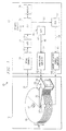
- FIGURE 1 is a diagrammatic view of a hard disk drive system 10 that depicts only the portions of the system 10 which are pertinent to an understanding of the teachings disclosed herein.
- the system 10 includes a disk/head assembly 12, and a control circuit 13.
- the disk/head assembly 12 includes a plurality of spaced and parallel disks 16, which are each fixedly supported on a spindle 17.
- the spindle 17 and the disks 16 together define a stack 18.
- the spindle 17 and the disks 16 thereon are rotatably driven by a (not-illustrated) spindle motor.
- the disks 16 each have on both sides thereof a magnetic coating, which stores information.
- the stored information on each side of each disk is organized in the form of a plurality of concentric tracks (not illustrated).
- Each track is broken into a plurality of arcuate and circumferentially distributed sectors.
- Each sector of each track includes servo information.
- the servo information provides position information, so that a read/write head may be properly positioned relative to the particular track on the particular disk 16.
- the disk/head assembly 12 further includes an actuator which is a voice coil motor (VCM) 21, and includes a plurality of support arms 22.
- the support arms 22 are pivotally supported on a stationary axle 23 that is substantially parallel to the spindle 17.
- the voice coil motor 21 urges simultaneous pivotal movement of the arms 22 about the axle 23.
- Each of the arms 22 has at the end thereof remote from the axle 23 a microactuator, one of which is shown at 26.
- the microactuator 26 is described in more detail later.
- Each microactuator supports a respective read/write head, one such read/write head being shown at 27.
- Each read/write head is disposed adjacent a respective side of a respective disk 16 of the stack 18.
- the voice coil motor 21 pivots the axle 23 and all of the support arms 22, the read/write heads 27 each move approximately radially with respect to the adjacent disk 16 in the stack 18.
- each microactuator 26 can effect a small amount of movement of the read/write head 27 thereon relative to the associated support arm 22, in a direction which causes the read/write head 27 to move approximately radially with respect to the adjacent disk 16 in the stack 18.
- Each read/write head 27 can read data from or write data to the associated disk 16, and can read the servo information from the disk 16. In general, just one read/write head 27 is active to read or write information at any given point in time.
- Servo information read from a disk 16 by a read/write head 27 is supplied at 31 as an analog servo information signal to a servo channel circuit 32, which is a part of the control circuit 13.
- the servo channel circuit 32 processes the analog servo information signal so as to generate an analog position signal, which is supplied at 33 to an analog-to-digital (A/D) converter circuit 34.
- the A/D converter circuit 34 converts the analog position signal 33 to a digital position signal, and supplies it at 35 to a digital signal processor (DSP) 36.
- DSP 36 is operatively coupled to a memory 38, which stores program instructions and data for the DSP 36.
- the DSP 36 receives at 41 a digital signal identifying a desired or target track, or in other words a track on one of the disks 16 with which the associated read/write head 27 is to be radially aligned.
- the desired or target track signal 41 may originate from a location external to the hard disk drive system 10, for example from a computer to which the hard disk drive system 10 is operationally coupled.
- the DSP 36 outputs at 46 a digital voice coil motor control signal, which is received by a digital-to-analog (D/A) converter circuit 47.
- the D/A circuit 47 converts the digital signal 46 to an analog signal, which is supplied at 48 to a voice coil motor power amplifier 51, which amplifies the analog voice coil motor control signal.
- the amplified signal from the output of the amplifier 51 is supplied at 52 to the voice coil motor 21.
- the voice coil motor 21 is responsive to the signal 52 to urge pivotal movement of the arms 22 about axle 23.
- the DSP 36 outputs at 56 a digital microactuator control signal, which is received by a further digital-to-analog (D/A) converter circuit 57.
- the D/A converter circuit 57 converts the digital microactuator control signal 56 to an analog signal, which is supplied at 58 to a microactuator power amplifier 61.
- the analog microactuator control signal is amplified by the amplifier 61, and then supplied to each of the microactuators 26, as shown diagrammatically at 62.
- the D/A converter circuit 57 and the amplifier 61 control all of the microactuators in the disclosed embodiment, it will be recognized that it would be possible to provide a separate D/A converter and amplifier for each microactuator, so that the DSP 41 could control the microactuators individually.
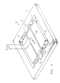
- FIGURE 2 is a diagrammatic perspective view of the microactuator 26.
- the microactuator 26 includes a base portion 71, and a member or platform 72 which is capable of a limited amount of movement relative to the base portion 71, in directions parallel to the arrows 73.
- the microactuator 26 has spring portions 76 and 77, which are disposed on opposite sides of the platform 72 and which urge movement of the platform 72 toward a central or equilibrium position. In the equilibrium position, the spring portions 76 and 77 do not exert any forces on the platform 72.
- the microactuator 26 further includes two permanent magnets 78 and 79, which are fixedly mounted on the base portion 71 on opposite sides of the platform 72.
- the magnets 78 and 79 are oriented to have inverse polarities.
- permanent magnets 78 and 79 are used in the disclosed embodiment, it will be recognized by one skilled in the art that a number of alternatives exist, for example, small coils could alternatively be used to generate electromagnetic fields.
- a coil 80 is fixedly mounted on the platform 72, so that opposite sides of the coil are disposed beneath the magnets 78 and 79. When a current is passed through the coil 80, a small electromagnetic field is generated and urges the platform 72 to move away from its equilibrium position in a direction determined by the polarity of the current.
- the platform will be urged in the same direction in the region of both magnets 78 and 79.
- the force exerted on the platform 72 in response to the coil current is a positioning force, and moves the platform 72 against the urging of the spring portions 76 and 77.
- the distance which the platform 72 moves away from the equilibrium position is directionally proportional to the magnitude of the current supplied to the coil 80. Because of the small size of the microactuator 26, and the small range of movement of the platform 72 relative to base portion 71, the speed with which the platform 72 can move relative to the base portion 71 is substantially faster than the speed with which the voice coil motor 21 (FIGURE 1) can pivot the arms 22.
- the base portion 71 of the microactuator 26 is fixedly secured on a support arm 22, with an orientation so that the direction indicated by arrows 73 is oriented approximately radially of the disks 16 in the platter stack 18.
- the associated read/write head 27 is fixedly supported on the platform 72.
- the read/write head 27 is moved approximately radially of the adjacent disk 16 in response to pivotal movement of the arms 22, or in response to movement of the associated actuator platform 72 in the direction of arrows 73.
- the spring portions 76 and 77 not only resist movement of the platform 72 and the read/write head 27 thereon away from the center or equilibrium position, but also provide support and alignment for the read/write head 27.
- the range of movement of the platform 72 in either direction away from its equilibrium position relative to the base portion 71 corresponds to movement of the associated read/write head 27 by approximately four or five tracks in either direction away from a track with which the read/write head is currently aligned.
- the microactuator 26 can effect movement of the platform 72 relative to base portion 71 much faster than the voice coil motor 21 can effect an equal amount of movement of the read/write head 27 by pivoting the arms 22. Therefore, primary control for positioning the read/write head 27 may be directed to the microactuator 26, and secondary control may be directed to the voice coil motor 21.
- the arms 22 will ideally be positioned so that there is no current flowing through the coil 80 of the microactuator, and thus the platform 72 will be in its equilibrium position.
- the read/write head 27 shifts slightly radially relative to the track, a small amount of current will be supplied to the coil 80 in order to rapidly move the platform 72 of the microactuator 26 until the read/write head 27 is again in radial alignment with that track. Then, the arms 22 would be pivoted slightly while decreasing the current flowing through the coil 80 to zero, so that the read/write head 27 remains in radial alignment with the track as the platform 72 moves to its equilibrium position. As another example, essentially the same approach would be used where the read/write head 27 is to be moved to a different track which is less than four or five tracks away from the current track, or in other words within the range of movement of the platform 72 of the microactuator 26.
- Still another example is a situation where the read/write head 27 is to be moved into radial alignment with a different track which is more than four or five tracks away from the current track, or in other words beyond the range of movement of the platform 72 relative to base portion 71.
- the target track might be ten tracks away from the current track.
- the primary control would attempt to use the microactuator 26 to rapidly position the read/write head 27 at the target track, but the platform 72 would reach the end of its range of travel after the read/write head moved four or five tracks and before the read/write head reached the target track. Further movement of the read/write head 27 toward the target track would then be effected through pivotal movement of the arms 22 by the voice coil motor 21.
- the current through the coil 80 would be progressively decreased as the arms 22 slowed to a stop, until the platform 72 reached its equilibrium position with the arms 22 positioned so that the read/write head 27 was in radial alignment with the target track.
- a system without a microactuator may limit the speed of pivotal movement of the arms 22 in order to avoid or minimize overshoot of the arms past their target position, because excessive overshoot and the resulting need for a corrective return movement could result in a longer seek time than simply moving the arms at a lower velocity.
- the arms 22 can be pivoted at a higher rate of speed than in a system without a microactuator, and can be allowed to overshoot their target position so long as the overshoot is less than four or five tracks.
- the microactuator 26 can keep the read/write head 27 in alignment with the target track while the arms 22 are carrying out the overshoot and the necessary corrective return.
- the current through the coil 80 of the microactuator 26 would be decreased to zero as the arms 22 moved to their target position, and then would be progressively increased with a reversed polarity as the arms 22 overshot their target position, so as to keep the read/write head in alignment with the target track. Thereafter, the reversed polarity current would be progressively decreased to zero during the corrective return of the arms 22 to their target position. If the arms 22 carried out a small amount of damped oscillation around their target position, the polarity of the current through the coil 80 of the microactuator might be changed several times in order to keep the read/write head 27 in accurate alignment with the target track during the oscillation.
- FIGURE 3 is a graph showing a situation where the read/write head 27 is moved to a new track which is only two tracks away from the current track, where the vertical axis represents tracks and the horizontal axis represents time. More specifically, the displacement of the microactuator platform 72 is shown at 86. It will be noted that there is an initial spike at 87 representing an initial displacement of the microactuator platform that effects rapid movement of the read/write head by a distance of approximately 1.75 tracks, which is most of the two-track displacement required for the read/write head to reach its new position. The movement of the outer end of the support arm 22 is indicated at 88. By the time the microactuator 26 has moved the read/write head through a distance of 1.75 tracks, the support arm 22 is just starting to move. The position of the read/write head 27 is represented by the curve 89. Since the movement of the read/write head 27 is the sum of the movements caused by the microactuator and the actuator arms 22, the curve 89 is the sum of the curves 86 and 88.
- the displacement of the microactuator platform 72 is gradually decreased until the microactuator platform is back in its equilibrium position, while the support arm 22 moves toward a new position in which it is displaced by a distance of two tracks from its original position. It will be noted that it takes the support arm between 0.004 and 0.005 seconds to reach its new position. Thus, if the microactuator was not present, it could take this long before the read/write head was aligned with the new track and could read or write information. In contrast, because of the provision of the microactuator, the read/write head reaches a position of steady alignment with the new track in less than 0.001 seconds, or in other words at least five times faster than in a system without a microactuator.
- FIGURE 4 is a graph depicting a situation where the read/write head is being moved to a target track which is ten tracks away from its current track.
- the displacement of the platform 72 of the microactuator is shown at 96, and includes an initial spike 97 that effects rapid movement of the read/write head 27 through a displacement of five tracks toward the new track. Since the range of movement of the microactuator platform is limited to about five tracks, further movement of the read/write head 27 toward the new track is effected by pivotal movement of the support arm 22.
- the movement of the read/write head 27 is the sum of the displacements of the microactuator platform and the support arm, and thus the curve 99 representing this movement is a sum of the curves 96 and 98.
- the current through the coil 80 is progressively reduced, so that the microactuator platform 72 is moved back toward its equilibrium position as the support arm 22 moves through the last five tracks of a ten-track displacement.
- the microactuator platform 72 reaches its equilibrium position at 103.
- the support arm 22 overshoots its target position at 101, and the microactuator is controlled after 103 so as to displace the platform 72 in a direction opposite its original displacement and by an amount sufficient to compensate for the overshoot of the support arm 22.
- the corrective movement of the support arm 22 does not bring the support arm 22 back to its target position until more than 0.01 seconds have elapsed from the start of movement. Nevertheless, because of the provision of the microactuator, the read/write head reaches its target position in approximately 0.0006 seconds after the start of movement, and is thereafter maintained in accurate alignment with the target track through appropriate control of the microactuator so as to compensate for the overshoot of the support arm 22.
- the position of the support arm 22 which differs from the position of the read/write head 27 by an amount equal to the displacement of the actuator platform 72 relative to the base portion 71. It would be possible to determine the actual position of the support arm 22 through the provision of a sensor, which directly sensed the position of the support arm 22, or which sensed the displacement of the actuator platform 72 relative to the base portion 71.
- the disclosed embodiment avoids the need to provide such a sensor, through the use of microactuator 26 which, as mentioned above, has a displacement that is proportional to the magnitude of the current supplied to the coil 80. That is, the direction and magnitude of the displacement of the platform 72 corresponds to the polarity and magnitude of the microactuator current.
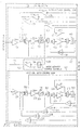
- FIGURE 5 includes a block diagram of a control system 106 which is implemented in the DSP 36 of FIGURE 1 in order to effect appropriate control of the microactuator 26 and the voice coil motor 21.
- Components in FIGURE which also appear in FIGURE 1 are designated in FIGURE 5 with the same reference numerals as in FIGURE 1.
- the movement of the support arms 22 by the voice coil motor 21 is shown diagrammatically at 109 in FIGURE 5.
- the forces which the spring portions 76 and 77 can exert on the read/write head 27 are shown diagrammatically at 111 and 112, and the positioning forces exerted on the read/write head 27 in response to a microactuator current through coil 80 are shown diagrammatically at 114.
- the control system 106 of FIGURE 5 includes a microactuator control loop 121, a voice coil motor control loop 122, a microactuator control technique 123, and a microactuator spring effect adjustment block 124.
- the microactuator control loop 121 is responsive to the desired or target position signal 41, and the digital position signal 35 from the A/D converter circuit 34.
- the microactuator control loop 121 is also responsive to the output of the microactuator spring effect adjustment block 124.
- the microactuator control loop 121 generates the digital microactuator control signal 56, which is supplied to the D/A converter circuit 57.
- the disclosed embodiment positions the read/write head 27 using the microactuator 26 for primary control and the voice coil motor 21 for secondary control.
- the voice coil motor 21 is controlled primarily as a slave or follower to the microactuator 26.
- the desired or target position signal 41 is supplied to the microactuator control loop 121, but not to the voice coil motor control loop 122.
- an output signal 128 from the microactuator control loop 121 is supplied to the microactuator control technique 123, which in turn outputs a signal 129 to the voice coil motor control loop 122.
- the microactuator control loop 121 thus effects the primary response to the desired or target position signal 41 through appropriate control of the microactuator 26, whereas the voice coil motor control loop 122 carries out a slave or follower function.
- the microactuator spring effect adjustment block 124 is responsive to signals 136 and 137 from the microactuator control loop 121 and the voice coil motor control loop 122, respectively.
- the signals 136 and 137 are indicative of the control implemented by the control loops 121 and 122.
- the microactuator spring effect adjustment block 124 outputs a signal 138, which is supplied to each of the control loops 121 and 122, and which is representative of at least one characteristic of the spring portions 76 and 77 of the microactuator 26.
- the microactuator control loop 121 includes a proportional gain element 151 which receives and scales the desired or target position signal 41 by a constant K1 ma .
- the output of the gain element 151 is coupled to a positive input of a junction 152, the output of which is coupled to an input of an amplifier 153 with a gain of K dma .
- the output of the amplifier 153 is coupled to a limit block 156 which applies a limit to the output signal from amplifier 153.
- the blocks 153 and 156 correspond functionally to the microactuator power amplifier 61, which operates with a five volt supply and thus cannot produce an output signal in excess of five volts.
- the output of the limit block 156 is coupled to a positive input of a junction 157, the output of which is coupled to the positive input of a junction 158.
- the output of the junction 158 is coupled to the input of a gain element 161.
- the gain of the element 161 is 1/Lma, where Lma represents an inductance which corresponds functionally to the inductance of the coil 80 of the microactuator 26.
- the output of the element 161 is coupled to a positive input of a junction 162, the output of which is coupled to an integrator 163.
- the integration function is designated symbolically by the LaPlace operator 1/s, which is normally associated with analog control loops, but it will be recognized that the integration function it represents may be implemented in the DSP 36 using an appropriate digital technique.
- the output of the integrator 163 is coupled to the input of a gain element 166, gain element 166 having a gain K tma that represents a motor force constant.
- the output of the gain element 166 is coupled to a positive input of a a junction 167, the output of which is coupled to an input of a gain element 168 having a gain of 1/J ma .
- J ma represents the combined mass of the microactuator platform 72 and the read/write head 27.
- the input to the gain element 168 is a force, and the output of the gain element 168 represents an acceleration.
- the output of element 168 is coupled to a positive input of a junction 171, the output of which is coupled to a further integrator 172.
- integrator 172 Since the input of integrator 172 is an acceleration, the output of integrator 172 represents velocity or speed.
- the output of integrator 172 is coupled to a positive input of a junction 173, the output of which is coupled to another integrator 176. Since the input to integrator 176 is a velocity or speed, the output of integrator 176 represents position, and in particular the estimated position of the platform 72 and thus the estimated position of the read/write head 27.
- the output of integrator 176 is coupled to a negative input of a junction 177.
- the actual position signal 35 from the A/D converter 34 is supplied to a positive input of the junction 177.
- the output of a the junction 177 thus represents a position error between the actual position of the read/write head, which is determined from the servo information read by the read/write head from the spinning disk, and the estimated position that the control loop 121 calculates the read/write head is theoretically expected to have in response to the control signals being output from the control system 106.
- the output of the junction 177 is coupled to the inputs of three gain elements 181-183, which have outputs respectively coupled to positive inputs of the junctions 162, 171 and 173, respectively.
- the gain elements 181-183 have respective gains of Lm3, Lm2 and Lm1, which are estimation gains that cause the elements 181-183 to function as state adjustors. That is, the elements 181-183 generate state adjustment values based on the position error from junction 177, and inject these values into the control loop through junctions 162, 171 and 173.
- the outputs of the elements 176, 172 and 168, which respectively represent position, velocity and acceleration, are coupled to inputs of respective gain elements 186-188, which have respective proportional gains of K1ma, K2ma and K3ma.
- the outputs of the gain elements 186-188 are coupled to respective negative inputs of the junction 152, and the elements 186-188 thus define respective feedback paths.
- the output of the element 172 is similarly coupled to the input of a further gain element 191, which has a gain Kbma representing the back emf of the coil 80 of the microactuator.
- the output of the element 191 is coupled to a negative input of the junction 157, thus defining a further feedback path.
- the output of the element 163 is coupled to the input of a gain element 164 having a gain Rma, which is representative of a resistance of the coil 80 of the microactuator.
- the output of the element 164 is coupled to a negative input of the junction 158, and the element 164 is thus part of another feedback path.
- the output of the junction 152 serves as the microactuator control signal 56, which is supplied through D/A converter circuit 57 to the microactuator power amplifier 61.
- the output of the limit element 156 serves as the signal 128 to the microactuator control technique 123.
- the signal 128 is representative of the direction and magnitude of the displacement of the platform 72 of the microactuator 26. Since a goal in controlling the voice coil motor 21 is to cause it to position the arm 22 so that the platform 72 is at its equilibrium position, or in other words has a displacement of zero, the signal 128 may be viewed as an error signal for purposes of controlling the voice coil motor 21. Accordingly, the input signal 129 to the voice coil motor control loop 122 is derived from the signal 128 through the control technique 123, for purposes of causing the control loop 122 to appropriately control the positioning arms 22.
- the microactuator control technique 123 includes an integrator 196 which receives and integrates the signal 128, the output of the integrator 196 being coupled to the input of a gain element 197.
- the gain element 197 has a gain Kct which is a constant.
- the output of the gain element 197 serves as the signal 129 supplied to the input of the voice coil motor control loop 122.
- the voice coil motor control loop 122 includes a gain element 201 which receives the signal 129, scales it by a proportional gain K1, and supplies the result to a positive input of a junction 202.
- the output of the junction 202 is coupled to an amplifier 203 having a gain of K drvr
- the output of the amplifier 203 is coupled to a limit element 206.
- the elements 203 and 206 together correspond functionally to the voice coil motor power amplifier 51, which works with a 12 volt supply and cannot produce an output signal in excess of 12 volts.
- the limit element 206 limits the magnitude of the output signal from the amplifier 203 to an appropriate range.
- the output of the limit element 206 is coupled to a positive input of a junction 207, the output of the junction 207 being coupled to the positive input of further junction 208.
- the output of junction 208 is coupled to the input of a gain element 211 which has a gain 1/Lm, where Lm is an inductance of a coil of the voice coil motor 21.
- the output of the gain element 211 is coupled to a positive input of a junction 212, the output of which is coupled to the input of an integrator 213.
- the output of the integrator 213 is coupled to the input of a gain element 216 having a gain Kt, where Kt is a torque constant for the coil of the voice coil motor 21.
- the output of the gain element 216 is coupled to the positive input of a junction 217, the output of which is coupled to the input of a gain element 218.
- the gain element 218 has a gain 1/Jm, where Jm represents the mass of the parts moved by the voice coil motor 21.
- the input to the element 218 represents a force, and the output represents acceleration.
- the output of the element 218 is coupled to the positive input of a junction 221, the output of which is coupled to the input of an integrator 222. Since the input to the integrator 222 represents acceleration, the output of the integrator 222 represents velocity, and is coupled to the positive input of a junction 223.
- the output of the junction 223 is coupled to the input of a further integrator 226, the output of which represents position.
- the output of the integrator 226 is coupled to the input of a gain element 227.
- the gain element 227 has a gain R, which represents the radial distance from the axle 23 (FIGURE 1) to the read/write head 27.
- the output of the gain element 227 represents position, and in particular the position of the support arms 22 rather than the position of the read/write head.
- the output of the gain element 227 is coupled to a negative input of a junction 228, the positive input to which is the actual position signal from line 35.
- the output of the junction 228 is thus an error signal representing the difference between the actual position of the read/write head indicated by the position signal 35, and the position which the control loop 122 calculates that the read/write head is theoretically expected to have in response to the control signals output from the control system 106.
- the error signal from junction 228 is supplied to the inputs of three gain elements 231-233.
- the gain elements 231-233 have respective gains of Lv3, Lv2 and Lv1, which are estimation gains that cause the gain elements to function as estimators.
- the outputs of the gain elements 231-233 are each coupled to a positive input of a respective one of the junctions 212, 221 and 223, in order to inject into the control loop respective estimator values developed from the error signal output by the junction 228.
- the outputs of the elements 226, 222, and 218 respectively represent position, velocity and acceleration.
- the outputs of the elements 226, 222, and 218 are coupled to the inputs of respective proportional gain elements 236-238, which have respective gains K1, K2 and K3.
- the outputs of the elements 236-238 are each coupled to a respective negative input of the junction 202, and the gain elements 236-238 are thus parts of respective feedback paths.
- the output of the element 222 is also coupled to the input of a further gain element 241.
- the gain element 241 has a gain Kb representing the back emf of the coil in the voice coil motor 21.
- the output of the gain element 241 is coupled to a negative input of the junction 207.
- the gain element 241 is thus part of a further feedback path.
- the output of the element 213 is coupled to the input of another gain element 242, which has a gain Rm representing a resistance of a coil in the voice coil motor 21.
- the output of the element 242 is coupled to a negative input of junction 208, and the element 242 thus is part of yet another feedback path.
- the microactuator spring effect adjustment block 124 includes a junction 246 with positive and negative inputs.
- the output of element 176 serves as the signal 136 which is coupled to the positive input of the junction 246, and the output of the element 227 serves as the signal 137 which is coupled to the negative input of the junction 246.
- the output of the junction 246 is coupled to an input of a gain element having a gain Kma, which is representative of a spring constant for the two spring portions 76 and 77 of the microactuator.
- the output of the element 247 is the signal 138, which is representative of the net force resulting from the opposed forces of the microactuator spring portions 76 and 77.
- the signal 138 is coupled to a negative input of the junction 167 and, through a gain element 249, to a positive input of the junction 217.
- the gain element 249 has a gain R, which is the same as the gain R of the element 227.
- the output of the junction 202 serves as the voice coil motor control signal supplied at 46 to the D/A converter 47.
- the microactuator control loop 121 takes the desired or target position signal 41 received through the gain element 151 and generates, with some feedback injected at the junction 152, an appropriate control signal 156 for the microactuator.
- the remaining elements of the microactuator control loop 121 combine the control signal 56 with real world characteristics of the electromechanical structure controlled by the signal 56, in order to derive at the output of the element 176 an expected or theoretical position of the read/write head 27. This theoretical or expected position is compared at 177 to the actual position of the read/write head indicated by signal 35, in order to develop an error signal that is fed back to the control loop through the estimator gain elements 181-183.
- the gain elements 186-188 respectively scale signals corresponding to the position, velocity and acceleration of the read/write head, and effect the feedback control through junction 152.
- the elements 164 and 191 provide feedback paths corresponding to respective characteristics of the microactuator coil. namely back emf and resistance.
- the effect of the microactuator springs, represented by the signal 138 from the microactuator spring effect adjustment block 124, is taken into account in the control loop 121 through the junction 167.
- the voice coil motor control loop 122 operates in a generally similar manner, except that the input signal 129 is based on the magnitude and direction of the displacement of the actuator platform from its equilibrium position. Thus, the control loop 122 controls the voice coil motor 21 as a slave or follower to the microactuator 26. Since the operation of the control loop 122 is generally similar to that of the control loop 121, a detailed explanation of the operation of the control loop 122 is believed unnecessary.
- the microactuator spring effect block 124 of FIGURE 6 models the primary characteristic of the microactuator spring portions 76 and 77, namely the net resilient force which they exert between the platform 72 and the base portion 71. However, there are secondary characteristics of the microactuator and the spring portions which may optionally be taken into account, including a damping characteristic and a stroke limit.
- FIGURE 7 shows a microactuator spring effect adjustment block 256 which is an alternative embodiment of and which may be substituted for the block 124 in FIGURE 6.
- the block 256 includes a junction 246 and a gain element 247, which are equivalent to those depicted in FIGURE 6 and are therefore identified with the same reference numerals.
- the output of the gain element 247 is coupled to a positive input of a junction 257, the output of which is a signal 138' that is functionally similar to the signal 138 of FIGURE 6.
- the output of the junction 246, which represents a position, is also coupled to the input of a differentiating element 259. Differentiation of a position yields a rate or velocity.
- the output of the differentiating element 259 is coupled to the input of a proportional gain element 261 which has a gain Dma, where Dma represents a damping characteristic of the microactuator spring portions 76 and 77.
- the output of the gain element 261 is coupled to a positive input of the junction 257.
- the block 256 also includes a stroke limit block 262 which receives the output signal from the junction 246.
- the stroke limit block 262 limits the magnitude of the signal from block 246 to a predefined range, in order to reflect the fact that the platform 72 of the microactuator 26 has a range of movement relative to the hase portion 71 which is physically limited.
- the output of the stroke limit block 262 is coupled to a proportional gain element 263 having a gain Kma1, where Kma1 is a scaling factor for the output of the stroke limit block 262.
- the output of the gain element 263 is coupled to a positive input of the junction 257.
- One such technical advantage of the disclosed apparatus is that a microactuator can be utilized in a hard disk drive, while avoiding the need to provide a position sensor to determine the actual position of the support member on which the microactuator movably supports the read/write head. This reduces the cost of the system, while achieving more efficient control through use of the dual actuator arrangement. In particular, seek times and thus access times are reduced.
- a further technical advantage is increased reliability, due to elimination of the need for a sensor and its associated support circuitry.
- the disclosed embodiment utilizes a digital signal processor to control the position of the read/write head, but it will be recognized that the position of the read/write head could also be controlled by an analog control circuit.
- a suitable control loop for the microactuator and a suitable control loop for the voice coil motor have been disclosed, but it will be recognized that there are many variations and modifications of these specific control loops which lie within the scope of the teachings disclosed herein.
Abstract
Description
- This invention relates in general to a control apparatus and, more particularly but not exclusively, to a method and apparatus for positioning a read/write head relative to a hard disk using a voice coil motor and a microactuator.
- A hard disk drive typically includes a rotating magnetic disk and a read/write head supported adjacent one side of the disk for approximately radial movement relative to the disk. Data on the disk is organized in the form of a plurality of concentric tracks, each track being subdivided into a plurality of arcuate sectors that are circumferentially distributed. Each track also includes servo information which can be read by the read/write head, which identifies the particular track, and which also indicates the extent to which the read/write head is or is not accurately radially aligned with that track.
- The read/write head is typically supported on a movable support arm, and an actuator such as a voice coil motor is provided in order to effect movement of the support arm. When the support arm is moved, the read/write head thereon is moved in a direction approximately radially of the disk. A control system is responsive to the servo information read from the disk by the read/write head for controlling the voice coil motor so as to position the support arm in a manner that radially aligns the read/write head with a selected track on the disk.
- The capacity of hard disk drives is progressively increasing, due in part to a progressive increase in the number of concentric tracks provided on a given hard disk. Of course, the radial widths of the tracks decrease as the number of tracks is increased. As a result, there has been an increase in the precision and resolution needed for controlling the radial position of the read/write head in order to keep it aligned with a particular track. A further consideration is that, as central processing units become progressively faster, there is an associated increase in the need for hard disk drives with faster seek and access times.
- One proposed approach for achieving greater precision and resolution while reducing seek and access times involves the use of a microactuator to movably support the read/write head on the support arm. Microactuators are miniature actuators or motors, which may be fabricated on silicon using semiconductor fabrication techniques, and which are sometimes referred to as micro-electro-mechanical systems (MEMS). A microactuator is capable of effecting rapid and accurate movement of the read/write head relative to the support arm, in a direction almost radially of the disk, but within a relatively small range of movement. The voice coil motor is thus used to move the support arm to effect coarse positioning of the read/write head, and the microactuator is used to effect fine positioning of the read/write head.
- The servo information read from the disk by the read/write head identifies only the position of the read/write head relative to the disk. In a typical hard disk drive system without a microactuator, the read/write head is fixedly supported on the support arm, and thus the position of the support arm is directly related to the position of the read/write head. ()n the other hand, when a microactuator is provided between the support arm and the read/write head, the microactuator facilitates movement of the read/write head relative to the support arm. Thus, knowledge of the actual position of the read/write head based on the servo information read from the disk provides no information at all regarding the actual position of the support arm.
- Accordingly, it has been considered necessary to supplement the position information from the read/write head with a sensor that determines the actual position of the support arm, either by directly sensing the position of the support arm, or by sensing the amount of relative movement effected by the microactuator between the support arm and read/write head. However, the need to provide such a sensor decreases the reliability of the system, while increasing its costs. In this regard, as storage capacity increases and the number of tracks increases, the actual position of the support arm must be determined with progressively increasing resolution and precision, which in turn involves increased cost and complexity for the sensor and associated circuitry that are provided to detect the actual position of the support arm. Consequently, while existing hard disk drives which use microactuators have been generally adequate for their intended purposes, they have not been satisfactory in all respects. due in part to the need to provide a sensor and supplementary circuitry.
- Particular and preferred aspects of the invention are set out in the accompanying independent and dependent claims. Features of the dependent claims may be combined with those of the independent claims as appropriate and in combinations other than those explicitly set out in the claims.
- According to first and second aspects of the invention, a method and apparatus are disclosed and involve: providing a first actuator to move a second part relative to a member; providing a second actuator to effect movement of the member relative to a first part, the first and second actuators each effecting relative movement of the first and second parts; receiving an input signal that specifies a target position of the second part relative to the first part; generating a first actuator control signal as a function of the input signal and without sensing an actual position of the member, the first actuator control signal causing the first actuator to move the second part toward the target position with respect to the first part; and generating a second actuator control signal as a function of the first actuator control signal and without sensing an actual position of the member, the second actuator control signal causing the second actuator to move the member in a manner so that the second part moves toward the target position with respect to the first part.
- According to a third aspect of the invention there is provided a control apparatus for controlling a system which includes a first part, a movable member, a first actuator supporting a second part on the member for movement relative to the member, and a second actuator operative to effect movement of the member, the first and second actuators each effecting relative movement of the first and second parts, wherein said control apparatus comprises:
- a first control portion having an input which receives an input signal that specifies a target position of the second part relative to the first part, said first control portion being operative to output a first actuator control signal for causing the first actuator to move the second part toward the target position with respect to the first part; and
- a second control portion having an input coupled to the first actuator control signal, said second control portion being operative to output a second actuator control signal to cause the second actuator to move the member in a manner so that the second part moves toward the target position with respect to the first part;
- wherein said apparatus is free of a sensor for sensing a position of said member.
-
- In an embodiment of the third aspect, the first actuator is a microactuator which effects relative movement of the first and second parts substantially faster than the second actuator effects relative movement of the first and second parts.
- In a further embodiment of the third aspect, the first actuator is a microactuator; and the apparatus is such that wherein a range of relative movement of the first and second parts effected by the second actuator is substantially greater than a range of relative movement of the first and second parts effected by the microactuator.
- The apparatus may include a position detection arrangement operative to detect an actual position of the second part relative to the first part; said first control portion being responsive to the position detection arrangement and being operative to generate the first actuator control signal as a function of the input signal and the actual position detected by the position detection arrangement.
- In a still further embodiment of the third aspect, the first actuator is a microactuator which has an initial state in which the second part is in a predetermined position with respect to the member; and wherein the microactuator is responsive to the first actuator control signal for moving the second part away from the predetermined position by a distance which is proportional to a magnitude of the first actuator control signal.
- In yet another embodiment of the third aspect, the first actuator is a microactuator which has an initial state in which the second part is in a predetermined position with respect to the member; wherein the microactuator is responsive to the first actuator control signal for moving the second part away from the predetermined position by a distance which is proportional to a magnitude of the first actuator control signal; and including a third control portion which is responsive to the first actuator control signal and which outputs a control signal obtained by subjecting the first actuator control signal to integration and a gain, said input of said second control portion receiving the control signal from said third control portion.
- In a still further embodiment of the third aspect, the first actuator is a microactuator which has an initial state in which the second part is in a predetermined position with respect to the member; wherein the microactuator is operative to move the second part away from the predetermined position in either of first and second directions which are opposite in response to the first actuator control signal respectively having positive and negative polarities; and wherein the microactuator includes a resilient arrangement responsive to movement of the second part away from the predetermined position in either of the first and second directions for urging movement of the second part toward the predetermined position.
- Moreover, there may be provided a force with which the resilient arrangement urges the sccond part toward the predetermined position increases as a distance of the second part from the predetermined position increases.
- In another embodiment of the third aspect, the first actuator is a microactuator which includes a resilient arrangement responsive to movement of the second part away from a predetermined position in either of two opposite directions relative to the member for urging movement of the second part toward the predetermined position, said first and second control portions respectively outputting first and second signals that respectively represent a position of the second part and a position of the member; and including a third control portion responsive to the first and second signals for generating a signal representing a force which the resilient arrangement is expected to be exerting between the second part and the member; said first and second control portions each being responsive to the signal from said third control portion.
- According to a fourth aspect of the invention there is provided a disk drive apparatus, comprising:
- a disk supported for rotation about an axis, and having thereon a magnetic surface;
- a member supported for movement relative to said disk;
- an actuator which is operative to effect movement of said member;
- a microactuator provided on said member;
- a read/write head supported by said microactuator for movement relative to said member, wherein movement of said member by said actuator corresponds to movement of said read/write head adjacent to and in a direction approximately radially of said surface of said disk, and wherein movement of said read/write head by said microactuator corresponds to movement of said read/write head adjacent to and in a direction approximately radially of said surface of said disk;
- a position detecting arrangement operative to generate a position signal representative of a position of said read/write head relative to said disk, said apparatus being free of an arrangement for sensing an actual position of said member; and
- a control system responsive to the position signal, and responsive to an input signal specifying a target position of said read/write head relative to said disk, said control system being operative to control said actuator and said microactuator so as to position said read/write head at the target position with respect to said disk.
-
- The control system may include a first portion responsive to the input signal for generating a microactuator control signal which is coupled to said microactuator, and a second portion that has an input and generates an actuator control signal which is coupled to said actuator, said microactuator having an initial state in which said read/write head is in a predetermined position with respect to said member, and being responsive to the microactuator control signal for moving said read/write head away from the predetermined position by distance which is proportional to a magnitude of the microactuator control signal. Moreover, a third control portion may be provided which is responsive to the microactuator control signal and which outputs a control signal obtained by subjecting the microactuator control signal to integration and a gain, said input of said second control portion being coupled to the control signal from said third control portion.
- Moreover, said microactuator may have an initial state in which said second part is in a predetermined position with respect to said member, said microactuator being operative to move said second part away from the predetermined position in either of first and second directions which are opposite in response to the microactuator control signal respectively having positive and negative polarities. Further, said microactuator may include a resilient portion responsive to movement of said second part away from the predetermined position in either of the first and second directions for urging movement of said second part toward the predetermined position.
- According to a fifth aspect of the invention there is provided a method for controlling a system which includes a first part, a movable member. a first actuator supporting a second part on the member for movement relative to the member, and a second actuator operative to effect movement of the member, the first and second actuators each effecting relative movement of the first and second parts, comprising the steps of:
- receiving an input signal that specifies a target position of the second part relative to the first part;
- generating a first actuator control signal as a function of the input signal and without sensing an actual position of the member, the first actuator control signal causing the first actuator to move the second part toward the target position with respect to the first part; and
- generating a second actuator control signal as a function of the first actuator control signal and without sensing an actual position of the member, the second actuator control signal causing the second actuator to move the member in a manner so that the second part moves toward the target position with respect to the first part.
-
- The method may be modified to include the step of causing the first actuator to respond to the first actuator control signal by moving the second part away from an initial position relative to the first part by a displacement which is proportional to the magnitude of the first actuator control signal and in a direction which corresponds to the polarity of the first actuator control signal; and wherein said step of generating the second actuator control signal includes the steps of subjecting the first actuator control signal to integration and a gain in order to obtain a modified signal, and then effecting feedback control of the position of the member by using the modified signal as a position error signal.
- It is thus possible to provide a method and apparatus for controlling a dual actuator system with just a single source of position information.
- A more complete understanding of the present invention will be realized from the detailed description which follows, taken in conjunction with the accompanying drawings, in which:
- FIGURE 1 is a block diagram of a hard disk drive system;
- FIGURE 2 is a diagrammatic perspective view of a microactuator which is a component of the hard disk drive system of FIGURE 1;
- FIGURES 3 and 4 are graphs showing operational characteristics of the hard disk drive system of FIGURE 1;
- FIGURE 5 is a block diagram of the hard disk drive system of FIGURE 1, showing in more detail a control system which is part of the hard disk drive system;
- FIGURES 6A and 6B, which are collectively referred to hereinafter as FIGURE 6, are respective portions of a block diagram showing in detail the control system of FIGURE 5; and
- FIGURE 7 is a block diagram of an alternative embodiment of a microactuator spring effect block that is a component of the control system of FIGURE 6.
-
- FIGURE 1 is a diagrammatic view of a hard
disk drive system 10 that depicts only the portions of thesystem 10 which are pertinent to an understanding of the teachings disclosed herein. Thesystem 10 includes a disk/head assembly 12, and acontrol circuit 13. - The disk/
head assembly 12 includes a plurality of spaced andparallel disks 16, which are each fixedly supported on aspindle 17. Thespindle 17 and thedisks 16 together define astack 18. Thespindle 17 and thedisks 16 thereon are rotatably driven by a (not-illustrated) spindle motor. Thedisks 16 each have on both sides thereof a magnetic coating, which stores information. The stored information on each side of each disk is organized in the form of a plurality of concentric tracks (not illustrated). Each track is broken into a plurality of arcuate and circumferentially distributed sectors. Each sector of each track includes servo information. The servo information provides position information, so that a read/write head may be properly positioned relative to the particular track on theparticular disk 16. - The disk/
head assembly 12 further includes an actuator which is a voice coil motor (VCM) 21, and includes a plurality ofsupport arms 22. Thesupport arms 22 are pivotally supported on astationary axle 23 that is substantially parallel to thespindle 17. Thevoice coil motor 21 urges simultaneous pivotal movement of thearms 22 about theaxle 23. Each of thearms 22 has at the end thereof remote from the axle 23 a microactuator, one of which is shown at 26. Themicroactuator 26 is described in more detail later. Each microactuator supports a respective read/write head, one such read/write head being shown at 27. - Each read/write head is disposed adjacent a respective side of a
respective disk 16 of thestack 18. When thevoice coil motor 21 pivots theaxle 23 and all of thesupport arms 22, the read/write heads 27 each move approximately radially with respect to theadjacent disk 16 in thestack 18. In addition, each microactuator 26 can effect a small amount of movement of the read/write head 27 thereon relative to the associatedsupport arm 22, in a direction which causes the read/write head 27 to move approximately radially with respect to theadjacent disk 16 in thestack 18. Each read/write head 27 can read data from or write data to the associateddisk 16, and can read the servo information from thedisk 16. In general, just one read/write head 27 is active to read or write information at any given point in time. - Servo information read from a
disk 16 by a read/write head 27 is supplied at 31 as an analog servo information signal to aservo channel circuit 32, which is a part of thecontrol circuit 13. Theservo channel circuit 32 processes the analog servo information signal so as to generate an analog position signal, which is supplied at 33 to an analog-to-digital (A/D)converter circuit 34. The A/D converter circuit 34 converts theanalog position signal 33 to a digital position signal, and supplies it at 35 to a digital signal processor (DSP) 36. TheDSP 36 is operatively coupled to amemory 38, which stores program instructions and data for theDSP 36. TheDSP 36 receives at 41 a digital signal identifying a desired or target track, or in other words a track on one of thedisks 16 with which the associated read/write head 27 is to be radially aligned. The desired ortarget track signal 41 may originate from a location external to the harddisk drive system 10, for example from a computer to which the harddisk drive system 10 is operationally coupled. - The
DSP 36 outputs at 46 a digital voice coil motor control signal, which is received by a digital-to-analog (D/A)converter circuit 47. The D/A circuit 47 converts thedigital signal 46 to an analog signal, which is supplied at 48 to a voice coilmotor power amplifier 51, which amplifies the analog voice coil motor control signal. The amplified signal from the output of theamplifier 51 is supplied at 52 to thevoice coil motor 21. Thevoice coil motor 21 is responsive to thesignal 52 to urge pivotal movement of thearms 22 aboutaxle 23. - The
DSP 36 outputs at 56 a digital microactuator control signal, which is received by a further digital-to-analog (D/A)converter circuit 57. The D/A converter circuit 57 converts the digitalmicroactuator control signal 56 to an analog signal, which is supplied at 58 to amicroactuator power amplifier 61. The analog microactuator control signal is amplified by theamplifier 61, and then supplied to each of themicroactuators 26, as shown diagrammatically at 62. Although the D/A converter circuit 57 and theamplifier 61 control all of the microactuators in the disclosed embodiment, it will be recognized that it would be possible to provide a separate D/A converter and amplifier for each microactuator, so that theDSP 41 could control the microactuators individually. - The
microactuator 26 will be briefly described in order to facilitate a better understanding of the exemplary embodiment. Themicroactuator 26 is a small actuator or motor fabricated in silicon for the purpose of moving a load through a small range of travel. FIGURE 2 is a diagrammatic perspective view of themicroactuator 26. Themicroactuator 26 includes abase portion 71, and a member orplatform 72 which is capable of a limited amount of movement relative to thebase portion 71, in directions parallel to thearrows 73. Themicroactuator 26 hasspring portions platform 72 and which urge movement of theplatform 72 toward a central or equilibrium position. In the equilibrium position, thespring portions platform 72. If theplatform 72 moves away from the equilibrium position in one direction parallel toarrows 73, twospring portions 76 are resiliently compressed and the twospring portions 77 are resiliently expanded, whereas if theplatform 72 is moved away from the equilibrium position in the opposite direction, the twospring portions 77 are resiliently compressed and the twospring portions 76 are resiliently expanded. - The
microactuator 26 further includes twopermanent magnets base portion 71 on opposite sides of theplatform 72. Themagnets permanent magnets coil 80 is fixedly mounted on theplatform 72, so that opposite sides of the coil are disposed beneath themagnets coil 80, a small electromagnetic field is generated and urges theplatform 72 to move away from its equilibrium position in a direction determined by the polarity of the current. Since themagnets coil 80 adjacent the magnets have respective current flows which are opposite, the platform will be urged in the same direction in the region of bothmagnets platform 72 in response to the coil current is a positioning force, and moves theplatform 72 against the urging of thespring portions - In
microactuator 26, the distance which theplatform 72 moves away from the equilibrium position is directionally proportional to the magnitude of the current supplied to thecoil 80. Because of the small size of themicroactuator 26, and the small range of movement of theplatform 72 relative tobase portion 71, the speed with which theplatform 72 can move relative to thebase portion 71 is substantially faster than the speed with which the voice coil motor 21 (FIGURE 1) can pivot thearms 22. - The
base portion 71 of themicroactuator 26 is fixedly secured on asupport arm 22, with an orientation so that the direction indicated byarrows 73 is oriented approximately radially of thedisks 16 in theplatter stack 18. The associated read/write head 27 is fixedly supported on theplatform 72. Thus, the read/write head 27 is moved approximately radially of theadjacent disk 16 in response to pivotal movement of thearms 22, or in response to movement of the associatedactuator platform 72 in the direction ofarrows 73. Thespring portions platform 72 and the read/write head 27 thereon away from the center or equilibrium position, but also provide support and alignment for the read/write head 27. In the disclosed embodiment, the range of movement of theplatform 72 in either direction away from its equilibrium position relative to thebase portion 71 corresponds to movement of the associated read/write head 27 by approximately four or five tracks in either direction away from a track with which the read/write head is currently aligned. Within this range of movement, themicroactuator 26 can effect movement of theplatform 72 relative tobase portion 71 much faster than thevoice coil motor 21 can effect an equal amount of movement of the read/write head 27 by pivoting thearms 22. Therefore, primary control for positioning the read/write head 27 may be directed to themicroactuator 26, and secondary control may be directed to thevoice coil motor 21. - In general, this means that a necessary positioning movement of the read/write head is first effected by using the
microactuator 26 to move the read/write head 27 toward the new position, while directing thevoice coil motor 21 to move thearms 22 until theplatform 72 of themicroactuator 26 has returned to its equilibrium position with the read/write head 27 aligned with a new track. For example, if the read/write head 27 is being maintained in radial alignment with a particular concentric track on the associateddisk 16, thearms 22 will ideally be positioned so that there is no current flowing through thecoil 80 of the microactuator, and thus theplatform 72 will be in its equilibrium position. If the read/write head 27 shifts slightly radially relative to the track, a small amount of current will be supplied to thecoil 80 in order to rapidly move theplatform 72 of themicroactuator 26 until the read/write head 27 is again in radial alignment with that track. Then, thearms 22 would be pivoted slightly while decreasing the current flowing through thecoil 80 to zero, so that the read/write head 27 remains in radial alignment with the track as theplatform 72 moves to its equilibrium position. As another example, essentially the same approach would be used where the read/write head 27 is to be moved to a different track which is less than four or five tracks away from the current track, or in other words within the range of movement of theplatform 72 of themicroactuator 26. - Still another example is a situation where the read/
write head 27 is to be moved into radial alignment with a different track which is more than four or five tracks away from the current track, or in other words beyond the range of movement of theplatform 72 relative tobase portion 71. For example, the target track might be ten tracks away from the current track. In this situation, the primary control would attempt to use themicroactuator 26 to rapidly position the read/write head 27 at the target track, but theplatform 72 would reach the end of its range of travel after the read/write head moved four or five tracks and before the read/write head reached the target track. Further movement of the read/write head 27 toward the target track would then be effected through pivotal movement of thearms 22 by thevoice coil motor 21. When the read/write head 27 reached the target track, the current through thecoil 80 would be progressively decreased as thearms 22 slowed to a stop, until theplatform 72 reached its equilibrium position with thearms 22 positioned so that the read/write head 27 was in radial alignment with the target track. - In this particular type of situation, a system without a microactuator may limit the speed of pivotal movement of the
arms 22 in order to avoid or minimize overshoot of the arms past their target position, because excessive overshoot and the resulting need for a corrective return movement could result in a longer seek time than simply moving the arms at a lower velocity. On the other hand, through the provision of themicroactuator 26, thearms 22 can be pivoted at a higher rate of speed than in a system without a microactuator, and can be allowed to overshoot their target position so long as the overshoot is less than four or five tracks. In particular, if the read/write head 27 is within four or five tracks of the target track, themicroactuator 26 can keep the read/write head 27 in alignment with the target track while thearms 22 are carrying out the overshoot and the necessary corrective return. - More specifically, as the read/
write head 27 reached the target track in this situation, the current through thecoil 80 of themicroactuator 26 would be decreased to zero as thearms 22 moved to their target position, and then would be progressively increased with a reversed polarity as thearms 22 overshot their target position, so as to keep the read/write head in alignment with the target track. Thereafter, the reversed polarity current would be progressively decreased to zero during the corrective return of thearms 22 to their target position. If thearms 22 carried out a small amount of damped oscillation around their target position, the polarity of the current through thecoil 80 of the microactuator might be changed several times in order to keep the read/write head 27 in accurate alignment with the target track during the oscillation. - FIGURE 3 is a graph showing a situation where the read/
write head 27 is moved to a new track which is only two tracks away from the current track, where the vertical axis represents tracks and the horizontal axis represents time. More specifically, the displacement of themicroactuator platform 72 is shown at 86. It will be noted that there is an initial spike at 87 representing an initial displacement of the microactuator platform that effects rapid movement of the read/write head by a distance of approximately 1.75 tracks, which is most of the two-track displacement required for the read/write head to reach its new position. The movement of the outer end of thesupport arm 22 is indicated at 88. By the time themicroactuator 26 has moved the read/write head through a distance of 1.75 tracks, thesupport arm 22 is just starting to move. The position of the read/write head 27 is represented by the curve 89. Since the movement of the read/write head 27 is the sum of the movements caused by the microactuator and theactuator arms 22, the curve 89 is the sum of thecurves 86 and 88. - Following the initial spike 87, the displacement of the
microactuator platform 72 is gradually decreased until the microactuator platform is back in its equilibrium position, while thesupport arm 22 moves toward a new position in which it is displaced by a distance of two tracks from its original position. It will be noted that it takes the support arm between 0.004 and 0.005 seconds to reach its new position. Thus, if the microactuator was not present, it could take this long before the read/write head was aligned with the new track and could read or write information. In contrast, because of the provision of the microactuator, the read/write head reaches a position of steady alignment with the new track in less than 0.001 seconds, or in other words at least five times faster than in a system without a microactuator. - FIGURE 4 is a graph depicting a situation where the read/write head is being moved to a target track which is ten tracks away from its current track. The displacement of the
platform 72 of the microactuator is shown at 96, and includes aninitial spike 97 that effects rapid movement of the read/write head 27 through a displacement of five tracks toward the new track. Since the range of movement of the microactuator platform is limited to about five tracks, further movement of the read/write head 27 toward the new track is effected by pivotal movement of thesupport arm 22. The movement of the read/write head 27 is the sum of the displacements of the microactuator platform and the support arm, and thus thecurve 99 representing this movement is a sum of thecurves - After the initial spike at 97, the current through the
coil 80 is progressively reduced, so that themicroactuator platform 72 is moved back toward its equilibrium position as thesupport arm 22 moves through the last five tracks of a ten-track displacement. As thesupport arm 22 reaches its target position, themicroactuator platform 72 reaches its equilibrium position at 103. However, thesupport arm 22 overshoots its target position at 101, and the microactuator is controlled after 103 so as to displace theplatform 72 in a direction opposite its original displacement and by an amount sufficient to compensate for the overshoot of thesupport arm 22. - As evident from FIGURE 4, the corrective movement of the
support arm 22 does not bring thesupport arm 22 back to its target position until more than 0.01 seconds have elapsed from the start of movement. Nevertheless, because of the provision of the microactuator, the read/write head reaches its target position in approximately 0.0006 seconds after the start of movement, and is thereafter maintained in accurate alignment with the target track through appropriate control of the microactuator so as to compensate for the overshoot of thesupport arm 22. - With reference to FIGURE 2, it will be recognized that, if the
support arm 22 and themicroactuator base portion 71 thereon are moved, the inertia of theplatform 72 and read/write head on the platform will tend to urge theplatform 72 to move relative to thebase portion 71. Thespring portions coil 80 in order to urge movement of theplatform 72, inertia of the read/write head 27 and theplatform 72 will initially cause thebase portion 71 and thesupport arm 22 to be urged in a direction opposite the direction of movement of theplatform 72. Again, thespring portions - In order to effect proper control of the position of the read/
write head 27, it is important to know the position of thesupport arm 22, which differs from the position of the read/write head 27 by an amount equal to the displacement of theactuator platform 72 relative to thebase portion 71. It would be possible to determine the actual position of thesupport arm 22 through the provision of a sensor, which directly sensed the position of thesupport arm 22, or which sensed the displacement of theactuator platform 72 relative to thebase portion 71. However, the disclosed embodiment avoids the need to provide such a sensor, through the use ofmicroactuator 26 which, as mentioned above, has a displacement that is proportional to the magnitude of the current supplied to thecoil 80. That is, the direction and magnitude of the displacement of theplatform 72 corresponds to the polarity and magnitude of the microactuator current. - FIGURE 5 includes a block diagram of a
control system 106 which is implemented in theDSP 36 of FIGURE 1 in order to effect appropriate control of themicroactuator 26 and thevoice coil motor 21. Components in FIGURE which also appear in FIGURE 1 are designated in FIGURE 5 with the same reference numerals as in FIGURE 1. - The movement of the
support arms 22 by thevoice coil motor 21 is shown diagrammatically at 109 in FIGURE 5. The forces which thespring portions write head 27 are shown diagrammatically at 111 and 112, and the positioning forces exerted on the read/write head 27 in response to a microactuator current throughcoil 80 are shown diagrammatically at 114. - The
control system 106 of FIGURE 5 includes amicroactuator control loop 121, a voice coilmotor control loop 122, amicroactuator control technique 123, and a microactuator springeffect adjustment block 124. Themicroactuator control loop 121 is responsive to the desired ortarget position signal 41, and the digital position signal 35 from the A/D converter circuit 34. Themicroactuator control loop 121 is also responsive to the output of the microactuator springeffect adjustment block 124. Themicroactuator control loop 121 generates the digitalmicroactuator control signal 56, which is supplied to the D/A converter circuit 57. - As previously mentioned, the disclosed embodiment positions the read/
write head 27 using themicroactuator 26 for primary control and thevoice coil motor 21 for secondary control. Stated differently, thevoice coil motor 21 is controlled primarily as a slave or follower to themicroactuator 26. Thus, in the disclosed embodiment, the desired ortarget position signal 41 is supplied to themicroactuator control loop 121, but not to the voice coilmotor control loop 122. Instead, anoutput signal 128 from themicroactuator control loop 121 is supplied to themicroactuator control technique 123, which in turn outputs asignal 129 to the voice coilmotor control loop 122. Themicroactuator control loop 121 thus effects the primary response to the desired ortarget position signal 41 through appropriate control of themicroactuator 26, whereas the voice coilmotor control loop 122 carries out a slave or follower function. - The microactuator spring
effect adjustment block 124 is responsive tosignals microactuator control loop 121 and the voice coilmotor control loop 122, respectively. Thesignals control loops effect adjustment block 124 outputs asignal 138, which is supplied to each of thecontrol loops spring portions microactuator 26. - The
control system 106 of FIGURE 5 is shown in more detail in FIGURE 6. With reference to FIGURE 6, themicroactuator control loop 121 includes aproportional gain element 151 which receives and scales the desired ortarget position signal 41 by a constant K1ma. The output of thegain element 151 is coupled to a positive input of ajunction 152, the output of which is coupled to an input of anamplifier 153 with a gain of Kdma. The output of theamplifier 153 is coupled to alimit block 156 which applies a limit to the output signal fromamplifier 153. Theblocks microactuator power amplifier 61, which operates with a five volt supply and thus cannot produce an output signal in excess of five volts. - The output of the
limit block 156 is coupled to a positive input of ajunction 157, the output of which is coupled to the positive input of ajunction 158. The output of thejunction 158 is coupled to the input of again element 161. The gain of theelement 161 is 1/Lma, where Lma represents an inductance which corresponds functionally to the inductance of thecoil 80 of themicroactuator 26. The output of theelement 161 is coupled to a positive input of ajunction 162, the output of which is coupled to anintegrator 163. The integration function is designated symbolically by theLaPlace operator 1/s, which is normally associated with analog control loops, but it will be recognized that the integration function it represents may be implemented in theDSP 36 using an appropriate digital technique. - The output of the
integrator 163 is coupled to the input of again element 166,gain element 166 having a gain Ktma that represents a motor force constant. The output of thegain element 166 is coupled to a positive input of a ajunction 167, the output of which is coupled to an input of again element 168 having a gain of 1/Jma. The term Jma represents the combined mass of themicroactuator platform 72 and the read/write head 27. The input to thegain element 168 is a force, and the output of thegain element 168 represents an acceleration. The output ofelement 168 is coupled to a positive input of ajunction 171, the output of which is coupled to afurther integrator 172. Since the input ofintegrator 172 is an acceleration, the output ofintegrator 172 represents velocity or speed. The output ofintegrator 172 is coupled to a positive input of ajunction 173, the output of which is coupled to anotherintegrator 176. Since the input tointegrator 176 is a velocity or speed, the output ofintegrator 176 represents position, and in particular the estimated position of theplatform 72 and thus the estimated position of the read/write head 27. - The output of
integrator 176 is coupled to a negative input of a junction 177. The actual position signal 35 from the A/D converter 34 is supplied to a positive input of the junction 177. The output of a the junction 177 thus represents a position error between the actual position of the read/write head, which is determined from the servo information read by the read/write head from the spinning disk, and the estimated position that thecontrol loop 121 calculates the read/write head is theoretically expected to have in response to the control signals being output from thecontrol system 106. The output of the junction 177 is coupled to the inputs of three gain elements 181-183, which have outputs respectively coupled to positive inputs of thejunctions junctions elements junction 152, and the elements 186-188 thus define respective feedback paths. The output of theelement 172 is similarly coupled to the input of afurther gain element 191, which has a gain Kbma representing the back emf of thecoil 80 of the microactuator. The output of theelement 191 is coupled to a negative input of thejunction 157, thus defining a further feedback path. The output of theelement 163 is coupled to the input of again element 164 having a gain Rma, which is representative of a resistance of thecoil 80 of the microactuator. The output of theelement 164 is coupled to a negative input of thejunction 158, and theelement 164 is thus part of another feedback path. - The output of the
junction 152 serves as themicroactuator control signal 56, which is supplied through D/A converter circuit 57 to themicroactuator power amplifier 61. The output of thelimit element 156 serves as thesignal 128 to themicroactuator control technique 123. Thesignal 128 is representative of the direction and magnitude of the displacement of theplatform 72 of themicroactuator 26. Since a goal in controlling thevoice coil motor 21 is to cause it to position thearm 22 so that theplatform 72 is at its equilibrium position, or in other words has a displacement of zero, thesignal 128 may be viewed as an error signal for purposes of controlling thevoice coil motor 21. Accordingly, theinput signal 129 to the voice coilmotor control loop 122 is derived from thesignal 128 through thecontrol technique 123, for purposes of causing thecontrol loop 122 to appropriately control the positioningarms 22. - More specifically, the
microactuator control technique 123 includes anintegrator 196 which receives and integrates thesignal 128, the output of theintegrator 196 being coupled to the input of again element 197. Thegain element 197 has a gain Kct which is a constant. The output of thegain element 197 serves as thesignal 129 supplied to the input of the voice coilmotor control loop 122. - The voice coil
motor control loop 122 includes again element 201 which receives thesignal 129, scales it by a proportional gain K1, and supplies the result to a positive input of ajunction 202. The output of thejunction 202 is coupled to anamplifier 203 having a gain of Kdrvr, and the output of theamplifier 203 is coupled to alimit element 206. Theelements motor power amplifier 51, which works with a 12 volt supply and cannot produce an output signal in excess of 12 volts. Thus, thelimit element 206 limits the magnitude of the output signal from theamplifier 203 to an appropriate range. - The output of the
limit element 206 is coupled to a positive input of ajunction 207, the output of thejunction 207 being coupled to the positive input offurther junction 208. The output ofjunction 208 is coupled to the input of again element 211 which has again 1/Lm, where Lm is an inductance of a coil of thevoice coil motor 21. The output of thegain element 211 is coupled to a positive input of ajunction 212, the output of which is coupled to the input of anintegrator 213. The output of theintegrator 213 is coupled to the input of again element 216 having a gain Kt, where Kt is a torque constant for the coil of thevoice coil motor 21. The output of thegain element 216 is coupled to the positive input of ajunction 217, the output of which is coupled to the input of again element 218. Thegain element 218 has again 1/Jm, where Jm represents the mass of the parts moved by thevoice coil motor 21. - The input to the
element 218 represents a force, and the output represents acceleration. The output of theelement 218 is coupled to the positive input of ajunction 221, the output of which is coupled to the input of anintegrator 222. Since the input to theintegrator 222 represents acceleration, the output of theintegrator 222 represents velocity, and is coupled to the positive input of ajunction 223. The output of thejunction 223 is coupled to the input of afurther integrator 226, the output of which represents position. The output of theintegrator 226 is coupled to the input of again element 227. Thegain element 227 has a gain R, which represents the radial distance from the axle 23 (FIGURE 1) to the read/write head 27. The output of thegain element 227 represents position, and in particular the position of thesupport arms 22 rather than the position of the read/write head. - The output of the
gain element 227 is coupled to a negative input of ajunction 228, the positive input to which is the actual position signal fromline 35. The output of thejunction 228 is thus an error signal representing the difference between the actual position of the read/write head indicated by theposition signal 35, and the position which thecontrol loop 122 calculates that the read/write head is theoretically expected to have in response to the control signals output from thecontrol system 106. - The error signal from
junction 228 is supplied to the inputs of three gain elements 231-233. The gain elements 231-233 have respective gains of Lv3, Lv2 and Lv1, which are estimation gains that cause the gain elements to function as estimators. The outputs of the gain elements 231-233 are each coupled to a positive input of a respective one of thejunctions junction 228. - As explained above, the outputs of the
elements elements junction 202, and the gain elements 236-238 are thus parts of respective feedback paths. - The output of the
element 222 is also coupled to the input of afurther gain element 241. Thegain element 241 has a gain Kb representing the back emf of the coil in thevoice coil motor 21. The output of thegain element 241 is coupled to a negative input of thejunction 207. Thegain element 241 is thus part of a further feedback path. The output of theelement 213 is coupled to the input of anothergain element 242, which has a gain Rm representing a resistance of a coil in thevoice coil motor 21. The output of theelement 242 is coupled to a negative input ofjunction 208, and theelement 242 thus is part of yet another feedback path. - The microactuator spring
effect adjustment block 124 includes ajunction 246 with positive and negative inputs. The output ofelement 176 serves as thesignal 136 which is coupled to the positive input of thejunction 246, and the output of theelement 227 serves as thesignal 137 which is coupled to the negative input of thejunction 246. The output of thejunction 246 is coupled to an input of a gain element having a gain Kma, which is representative of a spring constant for the twospring portions element 247 is thesignal 138, which is representative of the net force resulting from the opposed forces of themicroactuator spring portions signal 138 is coupled to a negative input of thejunction 167 and, through again element 249, to a positive input of thejunction 217. Thegain element 249 has a gain R, which is the same as the gain R of theelement 227. The output of thejunction 202 serves as the voice coil motor control signal supplied at 46 to the D/A converter 47. - In general terms. the
microactuator control loop 121 takes the desired ortarget position signal 41 received through thegain element 151 and generates, with some feedback injected at thejunction 152, anappropriate control signal 156 for the microactuator. The remaining elements of themicroactuator control loop 121 combine thecontrol signal 56 with real world characteristics of the electromechanical structure controlled by thesignal 56, in order to derive at the output of theelement 176 an expected or theoretical position of the read/write head 27. This theoretical or expected position is compared at 177 to the actual position of the read/write head indicated bysignal 35, in order to develop an error signal that is fed back to the control loop through the estimator gain elements 181-183. - The gain elements 186-188 respectively scale signals corresponding to the position, velocity and acceleration of the read/write head, and effect the feedback control through
junction 152. Theelements signal 138 from the microactuator springeffect adjustment block 124, is taken into account in thecontrol loop 121 through thejunction 167. - The voice coil
motor control loop 122 operates in a generally similar manner, except that theinput signal 129 is based on the magnitude and direction of the displacement of the actuator platform from its equilibrium position. Thus, thecontrol loop 122 controls thevoice coil motor 21 as a slave or follower to themicroactuator 26. Since the operation of thecontrol loop 122 is generally similar to that of thecontrol loop 121, a detailed explanation of the operation of thecontrol loop 122 is believed unnecessary. - The microactuator spring effect block 124 of FIGURE 6 models the primary characteristic of the
microactuator spring portions platform 72 and thebase portion 71. However, there are secondary characteristics of the microactuator and the spring portions which may optionally be taken into account, including a damping characteristic and a stroke limit. - More specifically, FIGURE 7 shows a microactuator spring
effect adjustment block 256 which is an alternative embodiment of and which may be substituted for theblock 124 in FIGURE 6. With reference to FIGURE 7, theblock 256 includes ajunction 246 and again element 247, which are equivalent to those depicted in FIGURE 6 and are therefore identified with the same reference numerals. The output of thegain element 247 is coupled to a positive input of ajunction 257, the output of which is a signal 138' that is functionally similar to thesignal 138 of FIGURE 6. - The output of the
junction 246, which represents a position, is also coupled to the input of a differentiatingelement 259. Differentiation of a position yields a rate or velocity. The output of the differentiatingelement 259 is coupled to the input of aproportional gain element 261 which has a gain Dma, where Dma represents a damping characteristic of themicroactuator spring portions gain element 261 is coupled to a positive input of thejunction 257. Theblock 256 also includes astroke limit block 262 which receives the output signal from thejunction 246. Thestroke limit block 262 limits the magnitude of the signal fromblock 246 to a predefined range, in order to reflect the fact that theplatform 72 of themicroactuator 26 has a range of movement relative to thehase portion 71 which is physically limited. The output of thestroke limit block 262 is coupled to aproportional gain element 263 having a gain Kma1, where Kma1 is a scaling factor for the output of thestroke limit block 262. The output of thegain element 263 is coupled to a positive input of thejunction 257. - One such technical advantage of the disclosed apparatus is that a microactuator can be utilized in a hard disk drive, while avoiding the need to provide a position sensor to determine the actual position of the support member on which the microactuator movably supports the read/write head. This reduces the cost of the system, while achieving more efficient control through use of the dual actuator arrangement. In particular, seek times and thus access times are reduced. A further technical advantage is increased reliability, due to elimination of the need for a sensor and its associated support circuitry.
- Although one embodiment has been illustrated and described in detail, it should be understood that various changes, substitutions and alterations can be made therein without departing from the scope of the teachings disclosed herein. For example, the disclosed embodiment utilizes a digital signal processor to control the position of the read/write head, but it will be recognized that the position of the read/write head could also be controlled by an analog control circuit. Moreover, a suitable control loop for the microactuator and a suitable control loop for the voice coil motor have been disclosed, but it will be recognized that there are many variations and modifications of these specific control loops which lie within the scope of the teachings disclosed herein. In this regard, it will be recognized that direct connections disclosed herein could be altered, such that two disclosed components or elements are coupled to one another through an intermediate device or devices without being directly connected, while still realizing the apparatus disclosed herein. Other changes, substitutions and alterations are also possible without departing from the spirit and scope of the disclosed teachings.
Claims (26)
- Control apparatus comprising:a first control portion having an input for receiving an input signal that specifies a target position of a second part relative to a first part, said first control portion being operative to output a first actuator control signal for causing a first actuator to move the second part toward the target position with respect to the first part; anda second control portion having an input for receiving the first actuator control signal and operative to output a second actuator control signal for causing a second actuator to move a member in a manner such that the second part moves toward the target position with respect to the first part; andwherein the first actuator is mounted on the member such that movement thereof causes movement of the second part relative to the member.
- Apparatus according to claim 1, wherein the first actuator is configured to effect relative movement of the first and second parts at speeds substantially faster than those at which the second actuator is configured to effect relative movement of the first and second parts.
- Apparatus according to claim 1 or claim 2, wherein a range of relative movement of the first and second parts effected by the second actuator is substantially greater than a range of relative movement of the first and second parts effected by the first actuator.
- Apparatus according to any preceding claim further comprising:
a position detection arrangement operative to detect an actual position of the second part relative to the first part; said first control portion being responsive to the position detection arrangement and operative to generate the first actuator control signal as a function of the input signal and the actual position detected by the position detection arrangement. - Apparatus according to any preceding claim, wherein the first actuator has an initial state in which the second part is in a predetermined position with respect to the member; and wherein the first actuator is responsive to the first actuator control signal for moving the second part away from the predetermined position by a distance which is proportional to a magnitude of the first actuator control signal.
- Apparatus according to any preceding claim, further comprising:
a third control portion which is responsive to the first actuator control signal and which outputs a control signal obtained by subjecting the first actuator control signal to an integration function and a gain function, said input of said second control portion receiving the control signal from said third control portion. - Apparatus according to any preceding claim, wherein the lirst actuator is operative to move the second part away from the predetermined position in either of first and second directions which are opposite in response to the first actuator control signal respectively having positive and negative polarities.
- Apparatus according to claim 7, wherein the first actuator comprises a resilient arrangement responsive to movement of the second part away from the predetermined position in either of the first and second directions for urging movement of the second part toward the predetermined position.
- Apparatus according to claim 8, wherein a force with which the resilient arrangement urges the second part toward the predetermined position increases as a distance of the second part from the predetermined position increases.
- Apparatus according to any preceding claim, wherein said first and second control portions respectively are arranged for outputting first and second signals that respectively represent a position of the second part and a position of the member.
- Apparatus according to claim 10, wherein said third control portion is responsive to the first and second signals for generating a signal representing a force which the resilient arrangement is expected to be exerting between the second part and the member; said first and second control portions each being responsive to the signal from said third control portion.
- A disk drive apparatus, comprising:a disk supported for rotation about an axis;an actuator operative to effect movement of a member relative to said disk;a microactuator provided on said member;a read/write head supported by said microactuator for movement relative to said member, wherein movement of said member by said actuator corresponds to movement of said read/write head adjacent to and in a direction approximately radially of a surface of said disk, and wherein movement of said read/write head by said microactuator corresponds to movement of said read/write head adjacent to and in a direction approximately radially of said surface of said disk;a position detecting arrangement operative to generate a position signal representative of a position of said read/write head relative to said disk; andcontrol means responsive to the position signal, and responsive to an input signal specifying a target position of said read/write head relative to said disk, said control means being operative to control said actuator and said microactuator so as to position said read/write head at the target position with respect to said disk.
- Apparatus according to claim 12, wherein said microactuator effects relative movement of said read/write head and said disk at a speed which is substantially faster than a speed at which said actuator effects relative movement of said read/write head and said disk.
- Apparatus according to claim 12 or claim 13, wherein said actuator effects a range of relative movement of said read/write head and said disk which is substantially greater than a range of relative movement thereof effected by said microactuator.
- Apparatus according to any one of claims 12 to 14, wherein said control means comprises a first portion responsive to the input signal for generating a microactuator control signal which is coupled to said microactuator, and a second portion responsive to the microactuator control signal for generating an actuator control signal which is coupled to said actuator.
- Apparatus according to any one of claims 12 to 15, wherein said microactuator has an initial state in which said read/write head is in a predetermined position with respect to the member; and wherein said microactuator is responsive to the microactuator control signal for moving said read/write head away from the predetermined position by a distance which is proportional to a magnitude of the microactuator control signal.
- Apparatus according to any one of claims 12 to 16, wherein said control system comprises a first portion responsive to the input signal for generating a microactuator control signal which is coupled to said microactuator and a second portion that has an input and is arranged for generating an actuator control signal which is coupled to said actuator.
- Apparatus according to any one of claims 12 to 17, further comprising:
a third control portion which is responsive to the microactuator control signal and which outputs a control signal obtained by subjecting the microactuator control signal to an integration function and a gain function, said input of said second control portion being coupled to the control signal from said third control portion. - Apparatus according to any one of claims 12 to 18, wherein said microactuator is operative to move said second part away from the predetermined position in either of first and second directions which are opposite in response to the microactuator control signal respectively having positive and negative polarities.
- Apparatus according to claim 19, wherein said microactuator comprises a resilient portion responsive to movement of said second part away from the predetermined position in either of the first and second directions for urging movement of said second part toward the predetermined position.
- Apparatus according to any one of claims 12 to 20, wherein the disk is a magnetic disk having a magnetic surface for cooperating with the read/write head.
- A method for controlling movement of a second part relative to a first part, which method comprises:wherein said first actuator is mounted on the member such that movement thereof causes movement of the second part relative to the member.receiving an input signal that specifies a target position of a second part relative to a first part;generating a first actuator control signal as a function of the input signal for causing the first actuator to move the second part toward the target position with respect to the first part;generating a second actuator control signal as a function of the first actuator control signal for causing the second actuator to move the member in a manner so that the second part moves toward the target position with respect to the first part; and
- The method according to claim 22 further comprising:
detecting an actual position of the second part relative to the first part; and wherein said step of generating the first actuator control signal is carried out by generating the first actuator control signal as a function of the input signal and the detected position of the second part relative to the first part. - The method according to claim 22 or claim 23 further comprising:
causing the first actuator to respond to the first actuator control signal by moving the second part away from an initial position relative to the first part by a displacement which is proportional to the magnitude of the first actuator control signal. - The method according to claim 24 further comprising:
causing the first actuator to respond to the first actuator control signal by moving the second part away from an initial position relative to the first part in a direction which corresponds to the polarity of the lirst actuator control signal; and wherein said step of generating the second actuator control signal comprises subjecting the first actuator control signal to an integration function and a gain function in order to obtain a modified signal, and then effecting feedback control of the position of the member by using the modified signal as a position error signal. - An apparatus according to any one of claims 1 to 11, or a method according to any one of claims 22 to 25, wherein the or each actuator is a microactuator.
Applications Claiming Priority (2)
| Application Number | Priority Date | Filing Date | Title |
|---|---|---|---|
| US08/992,598 US6424486B2 (en) | 1997-12-17 | 1997-12-17 | Method and apparatus for positioning a read/write head of a hard disk drive |
| US992598 | 1997-12-17 |
Publications (3)
| Publication Number | Publication Date |
|---|---|
| EP0924689A2 true EP0924689A2 (en) | 1999-06-23 |
| EP0924689A3 EP0924689A3 (en) | 1999-08-25 |
| EP0924689B1 EP0924689B1 (en) | 2012-09-19 |
Family
ID=25538512
Family Applications (1)
| Application Number | Title | Priority Date | Filing Date |
|---|---|---|---|
| EP98310075A Expired - Lifetime EP0924689B1 (en) | 1997-12-17 | 1998-12-09 | Control apparatus and method |
Country Status (6)
| Country | Link |
|---|---|
| US (1) | US6424486B2 (en) |
| EP (1) | EP0924689B1 (en) |
| JP (1) | JPH11260006A (en) |
| KR (1) | KR19990063112A (en) |
| SG (1) | SG74101A1 (en) |
| TW (1) | TW408318B (en) |
Cited By (6)
| Publication number | Priority date | Publication date | Assignee | Title |
|---|---|---|---|---|
| WO2000063894A2 (en) * | 1999-04-21 | 2000-10-26 | Seagate Technology Llc | Dual stage servo controller |
| WO2001022409A1 (en) * | 1999-09-23 | 2001-03-29 | Seagate Technology Llc | Method and control scheme for compensating the coarse actuators undesired transients in dual stage control systems |
| WO2001031643A1 (en) * | 1999-10-28 | 2001-05-03 | Seagate Technology Llc | Microactuator-induced reactive forces for fine positioning a sensor |
| US6563665B1 (en) | 1999-07-23 | 2003-05-13 | Seagate Technology Llc | PQ enhanced observer based dual stage servo controller |
| US6590734B1 (en) | 1999-08-25 | 2003-07-08 | Seagate Technology Llc | Observer based dual stage servo controller with gain boost to accomodate rotational vibration |
| US6674605B1 (en) | 1999-04-21 | 2004-01-06 | Seagate Technology Llc | PQ enhanced dual stage servo controller |
Families Citing this family (19)
| Publication number | Priority date | Publication date | Assignee | Title |
|---|---|---|---|---|
| KR100611963B1 (en) * | 1999-11-25 | 2006-08-11 | 삼성전자주식회사 | Dual-stage servo system using feedforward learning control input |
| US20030076121A1 (en) * | 2001-10-23 | 2003-04-24 | Wei Guo | Peizoelectric microactuator and sensor failure detection in disk drives |
| TWI254927B (en) * | 2001-11-23 | 2006-05-11 | Via Tech Inc | Method and apparatus for long seeking control of pickup head |
| JP4010400B2 (en) | 2002-06-14 | 2007-11-21 | シャープ株式会社 | Semiconductor memory device and data write control method |
| US7096378B2 (en) * | 2002-08-29 | 2006-08-22 | Freescale Semiconductor, Inc. | Data storage system having a non-volatile IC based memory for storing user data |
| US6646948B1 (en) * | 2002-08-29 | 2003-11-11 | Motorola, Inc. | Data storage system utilizing a non-volatile IC based memory for reduction of data retrieval time |
| US7170706B2 (en) * | 2002-08-29 | 2007-01-30 | Freescale Semiconductor, Inc. | Hard disk system with non-volatile IC based memory for storing data |
| US7006318B2 (en) | 2002-08-29 | 2006-02-28 | Freescale Semiconductor, Inc. | Removable media storage system with memory for storing operational data |
| KR100494387B1 (en) | 2002-11-19 | 2005-06-13 | 삼성전자주식회사 | Disk writer and writing method thereof |
| US6975482B1 (en) * | 2003-03-06 | 2005-12-13 | Maxtor Corporation | Settle control systems and methods for the second stage of a dual stage actuator |
| US7136257B2 (en) * | 2003-05-16 | 2006-11-14 | Seagate Technology Llc | Apparatus and method for maintaining stability in a disc drive servo loop |
| US7127549B2 (en) * | 2004-02-04 | 2006-10-24 | Sandisk Corporation | Disk acceleration using first and second storage devices |
| US7136973B2 (en) * | 2004-02-04 | 2006-11-14 | Sandisk Corporation | Dual media storage device |
| US9104315B2 (en) | 2005-02-04 | 2015-08-11 | Sandisk Technologies Inc. | Systems and methods for a mass data storage system having a file-based interface to a host and a non-file-based interface to secondary storage |
| US7627733B2 (en) | 2005-08-03 | 2009-12-01 | Sandisk Corporation | Method and system for dual mode access for storage devices |
| US7793068B2 (en) | 2005-12-21 | 2010-09-07 | Sandisk Corporation | Dual mode access for non-volatile storage devices |
| US7747837B2 (en) | 2005-12-21 | 2010-06-29 | Sandisk Corporation | Method and system for accessing non-volatile storage devices |
| US7769978B2 (en) * | 2005-12-21 | 2010-08-03 | Sandisk Corporation | Method and system for accessing non-volatile storage devices |
| JP5953004B2 (en) * | 2011-02-08 | 2016-07-13 | 日本発條株式会社 | Magnetic disk unit |
Citations (8)
| Publication number | Priority date | Publication date | Assignee | Title |
|---|---|---|---|---|
| US3924268A (en) * | 1974-08-05 | 1975-12-02 | Ibm | High density track follower control system for magnetic disk file |
| US4858040A (en) * | 1987-08-25 | 1989-08-15 | Ampex Corporation | Bimorph actuator for a disk drive |
| US5177652A (en) * | 1989-04-07 | 1993-01-05 | Hitachi, Ltd. | Dual-actuator transducer position control apparatus for seeking and following track on rotary disk |
| US5189578A (en) * | 1989-06-28 | 1993-02-23 | Hitachi, Ltd. | Disk system with sub-actuators for fine head displacement |
| US5216559A (en) * | 1990-06-01 | 1993-06-01 | Iomega Corporation | Carrier structure for read/write heads |
| US5452275A (en) * | 1991-07-04 | 1995-09-19 | Mitsubishi Denki Kabushiki Kaisha | Two-stage actuator control device |
| EP0763881A2 (en) * | 1995-09-13 | 1997-03-19 | Hewlett-Packard Company | Magnetic micro-mover |
| JPH09180382A (en) * | 1995-12-26 | 1997-07-11 | Tdk Corp | Magnetic disk device |
Family Cites Families (2)
| Publication number | Priority date | Publication date | Assignee | Title |
|---|---|---|---|---|
| US5920441A (en) * | 1995-09-22 | 1999-07-06 | International Business Machines Corporation | Method and apparatus for controlling a multiple-stage actuator for a disk drive |
| US5901010A (en) * | 1997-02-07 | 1999-05-04 | Cirrus Logic, Inc. | Magnetic disc recording system employing two stage actuators for simultaneous accesses through multiple recording heads |
-
1997
- 1997-12-17 US US08/992,598 patent/US6424486B2/en not_active Expired - Lifetime
-
1998
- 1998-12-02 SG SG1998005134A patent/SG74101A1/en unknown
- 1998-12-09 EP EP98310075A patent/EP0924689B1/en not_active Expired - Lifetime
- 1998-12-15 TW TW087120783A patent/TW408318B/en not_active IP Right Cessation
- 1998-12-16 KR KR1019980055413A patent/KR19990063112A/en not_active Application Discontinuation
- 1998-12-17 JP JP10359573A patent/JPH11260006A/en active Pending
Patent Citations (8)
| Publication number | Priority date | Publication date | Assignee | Title |
|---|---|---|---|---|
| US3924268A (en) * | 1974-08-05 | 1975-12-02 | Ibm | High density track follower control system for magnetic disk file |
| US4858040A (en) * | 1987-08-25 | 1989-08-15 | Ampex Corporation | Bimorph actuator for a disk drive |
| US5177652A (en) * | 1989-04-07 | 1993-01-05 | Hitachi, Ltd. | Dual-actuator transducer position control apparatus for seeking and following track on rotary disk |
| US5189578A (en) * | 1989-06-28 | 1993-02-23 | Hitachi, Ltd. | Disk system with sub-actuators for fine head displacement |
| US5216559A (en) * | 1990-06-01 | 1993-06-01 | Iomega Corporation | Carrier structure for read/write heads |
| US5452275A (en) * | 1991-07-04 | 1995-09-19 | Mitsubishi Denki Kabushiki Kaisha | Two-stage actuator control device |
| EP0763881A2 (en) * | 1995-09-13 | 1997-03-19 | Hewlett-Packard Company | Magnetic micro-mover |
| JPH09180382A (en) * | 1995-12-26 | 1997-07-11 | Tdk Corp | Magnetic disk device |
Non-Patent Citations (1)
| Title |
|---|
| PATENT ABSTRACTS OF JAPAN vol. 97, no. 11, 28 November 1997 & JP 09 180382 A (TDK CORP), 11 July 1997 * |
Cited By (12)
| Publication number | Priority date | Publication date | Assignee | Title |
|---|---|---|---|---|
| WO2000063894A2 (en) * | 1999-04-21 | 2000-10-26 | Seagate Technology Llc | Dual stage servo controller |
| WO2000063894A3 (en) * | 1999-04-21 | 2001-01-04 | Seagate Technology Llc | Dual stage servo controller |
| GB2363248A (en) * | 1999-04-21 | 2001-12-12 | Seagate Technology Llc | PQ enhanced dual stage servo controller |
| US6674605B1 (en) | 1999-04-21 | 2004-01-06 | Seagate Technology Llc | PQ enhanced dual stage servo controller |
| US6563665B1 (en) | 1999-07-23 | 2003-05-13 | Seagate Technology Llc | PQ enhanced observer based dual stage servo controller |
| US6590734B1 (en) | 1999-08-25 | 2003-07-08 | Seagate Technology Llc | Observer based dual stage servo controller with gain boost to accomodate rotational vibration |
| WO2001022409A1 (en) * | 1999-09-23 | 2001-03-29 | Seagate Technology Llc | Method and control scheme for compensating the coarse actuators undesired transients in dual stage control systems |
| US6985327B2 (en) | 1999-09-23 | 2006-01-10 | Seagate Technology Llc | Method and control scheme for compensating the coarse actuators undesired transients in dual stage control systems |
| WO2001031643A1 (en) * | 1999-10-28 | 2001-05-03 | Seagate Technology Llc | Microactuator-induced reactive forces for fine positioning a sensor |
| GB2364595A (en) * | 1999-10-28 | 2002-01-30 | Seagate Technology Llc | Microactuator-induced reactive forces for fine positioning a sensor |
| US6542326B1 (en) | 1999-10-28 | 2003-04-01 | Seagate Technology Llc | Microactuator-induced reactive forces for fine positioning a sensor |
| GB2364595B (en) * | 1999-10-28 | 2004-03-03 | Seagate Technology Llc | Microactuator-induced reactive forces for fine positioning a sensor |
Also Published As
| Publication number | Publication date |
|---|---|
| JPH11260006A (en) | 1999-09-24 |
| EP0924689A3 (en) | 1999-08-25 |
| US6424486B2 (en) | 2002-07-23 |
| EP0924689B1 (en) | 2012-09-19 |
| US20010040754A1 (en) | 2001-11-15 |
| KR19990063112A (en) | 1999-07-26 |
| SG74101A1 (en) | 2000-07-18 |
| TW408318B (en) | 2000-10-11 |
Similar Documents
| Publication | Publication Date | Title |
|---|---|---|
| EP0924689B1 (en) | Control apparatus and method | |
| EP0572789B1 (en) | Apparatus and method for shock attenuation in a disk recording and/or reproduction system | |
| JP3263954B2 (en) | Method and apparatus for controlling motion of actuator arm assembly in disk drive mechanism | |
| JP3089709B2 (en) | Access servo mechanism for magnetic disk drive | |
| JP4947666B2 (en) | Sliding mode control of magnetoresistive read head for magnetic recording | |
| US5267110A (en) | Rotary actuator for a direct access storage device | |
| US6768610B1 (en) | Microactuator servo system in a disc drive | |
| WO1998020486A1 (en) | Actuator arm integrated piezoelectric microactuator | |
| KR20020013583A (en) | Microactuator-induced reactive forces for fine positioning a sensor | |
| KR100648747B1 (en) | Self tuning model reference controller in a disc drive | |
| EP0420696B1 (en) | Tracking control circuitry for an optical disk unit | |
| US6574070B2 (en) | Model reference generator for a disc drive | |
| US6490119B1 (en) | Method and apparatus for maintaining servo stability during actuator saturation | |
| JP2002538568A (en) | Closed-loop scaling for discrete time servo controllers in disk drives | |
| US6636375B1 (en) | Seek in a disc drive with nonlinear pivot friction | |
| JP2003503806A (en) | Active damping in actuator bearing translation mode | |
| US6469863B1 (en) | Active magnetic bearing system for improved servo control | |
| US6211638B1 (en) | Method and apparatus for linearizing control of a reluctance force motor | |
| US6169641B1 (en) | Methods and devices for controlling a head position actuator of a disk drive | |
| US6778350B2 (en) | Feed forward control of voice coil motor induced microactuator disturbance | |
| US6538840B1 (en) | Automatic method for optimizing throughput in a disc drive | |
| WO1998048412A2 (en) | Microactuator servo system in a disc drive | |
| JPH06150596A (en) | Magnetic disk device | |
| JPH05174517A (en) | Access servo mechanism for magnetic disc unit | |
| Chilumbu et al. | A novel suspension arm with 2-dimensional actuation, for flying height control and high-bandwidth track following in advanced hard disk drives |
Legal Events
| Date | Code | Title | Description |
|---|---|---|---|
| PUAI | Public reference made under article 153(3) epc to a published international application that has entered the european phase |
Free format text: ORIGINAL CODE: 0009012 |
|
| AK | Designated contracting states |
Kind code of ref document: A2 Designated state(s): DE FR GB IT NL |
|
| AX | Request for extension of the european patent |
Free format text: AL;LT;LV;MK;RO;SI |
|
| PUAL | Search report despatched |
Free format text: ORIGINAL CODE: 0009013 |
|
| AK | Designated contracting states |
Kind code of ref document: A3 Designated state(s): AT BE CH CY DE DK ES FI FR GB GR IE IT LI LU MC NL PT SE |
|
| AX | Request for extension of the european patent |
Free format text: AL;LT;LV;MK;RO;SI |
|
| 17P | Request for examination filed |
Effective date: 20000204 |
|
| AKX | Designation fees paid |
Free format text: DE FR GB IT NL |
|
| 17Q | First examination report despatched |
Effective date: 20030814 |
|
| GRAP | Despatch of communication of intention to grant a patent |
Free format text: ORIGINAL CODE: EPIDOSNIGR1 |
|
| GRAS | Grant fee paid |
Free format text: ORIGINAL CODE: EPIDOSNIGR3 |
|
| GRAA | (expected) grant |
Free format text: ORIGINAL CODE: 0009210 |
|
| AK | Designated contracting states |
Kind code of ref document: B1 Designated state(s): DE FR GB IT NL |
|
| REG | Reference to a national code |
Ref country code: GB Ref legal event code: FG4D |
|
| REG | Reference to a national code |
Ref country code: DE Ref legal event code: R096 Ref document number: 69842850 Country of ref document: DE Effective date: 20121115 |
|
| REG | Reference to a national code |
Ref country code: NL Ref legal event code: VDEP Effective date: 20120919 |
|
| PG25 | Lapsed in a contracting state [announced via postgrant information from national office to epo] |
Ref country code: NL Free format text: LAPSE BECAUSE OF FAILURE TO SUBMIT A TRANSLATION OF THE DESCRIPTION OR TO PAY THE FEE WITHIN THE PRESCRIBED TIME-LIMIT Effective date: 20120919 |
|
| PLBE | No opposition filed within time limit |
Free format text: ORIGINAL CODE: 0009261 |
|
| STAA | Information on the status of an ep patent application or granted ep patent |
Free format text: STATUS: NO OPPOSITION FILED WITHIN TIME LIMIT |
|
| 26N | No opposition filed |
Effective date: 20130620 |
|
| PG25 | Lapsed in a contracting state [announced via postgrant information from national office to epo] |
Ref country code: IT Free format text: LAPSE BECAUSE OF FAILURE TO SUBMIT A TRANSLATION OF THE DESCRIPTION OR TO PAY THE FEE WITHIN THE PRESCRIBED TIME-LIMIT Effective date: 20120919 |
|
| REG | Reference to a national code |
Ref country code: DE Ref legal event code: R097 Ref document number: 69842850 Country of ref document: DE Effective date: 20130620 |
|
| PGFP | Annual fee paid to national office [announced via postgrant information from national office to epo] |
Ref country code: GB Payment date: 20131126 Year of fee payment: 16 |
|
| PGFP | Annual fee paid to national office [announced via postgrant information from national office to epo] |
Ref country code: FR Payment date: 20131126 Year of fee payment: 16 |
|
| PGFP | Annual fee paid to national office [announced via postgrant information from national office to epo] |
Ref country code: DE Payment date: 20131230 Year of fee payment: 16 |
|
| REG | Reference to a national code |
Ref country code: DE Ref legal event code: R119 Ref document number: 69842850 Country of ref document: DE |
|
| GBPC | Gb: european patent ceased through non-payment of renewal fee |
Effective date: 20141209 |
|
| REG | Reference to a national code |
Ref country code: FR Ref legal event code: ST Effective date: 20150831 |
|
| PG25 | Lapsed in a contracting state [announced via postgrant information from national office to epo] |
Ref country code: DE Free format text: LAPSE BECAUSE OF NON-PAYMENT OF DUE FEES Effective date: 20150701 Ref country code: GB Free format text: LAPSE BECAUSE OF NON-PAYMENT OF DUE FEES Effective date: 20141209 |
|
| PG25 | Lapsed in a contracting state [announced via postgrant information from national office to epo] |
Ref country code: FR Free format text: LAPSE BECAUSE OF NON-PAYMENT OF DUE FEES Effective date: 20141231 |