EP0805439A1 - Compensation for radial and vertical runout of an optical disc - Google Patents
Compensation for radial and vertical runout of an optical disc Download PDFInfo
- Publication number
- EP0805439A1 EP0805439A1 EP97201160A EP97201160A EP0805439A1 EP 0805439 A1 EP0805439 A1 EP 0805439A1 EP 97201160 A EP97201160 A EP 97201160A EP 97201160 A EP97201160 A EP 97201160A EP 0805439 A1 EP0805439 A1 EP 0805439A1
- Authority
- EP
- European Patent Office
- Prior art keywords
- tracking
- actuator
- lens
- current
- optical disc
- Prior art date
- Legal status (The legal status is an assumption and is not a legal conclusion. Google has not performed a legal analysis and makes no representation as to the accuracy of the status listed.)
- Granted
Links
Images


Classifications
-
- G—PHYSICS
- G11—INFORMATION STORAGE
- G11B—INFORMATION STORAGE BASED ON RELATIVE MOVEMENT BETWEEN RECORD CARRIER AND TRANSDUCER
- G11B7/00—Recording or reproducing by optical means, e.g. recording using a thermal beam of optical radiation by modifying optical properties or the physical structure, reproducing using an optical beam at lower power by sensing optical properties; Record carriers therefor
- G11B7/08—Disposition or mounting of heads or light sources relatively to record carriers
- G11B7/09—Disposition or mounting of heads or light sources relatively to record carriers with provision for moving the light beam or focus plane for the purpose of maintaining alignment of the light beam relative to the record carrier during transducing operation, e.g. to compensate for surface irregularities of the latter or for track following
- G11B7/095—Disposition or mounting of heads or light sources relatively to record carriers with provision for moving the light beam or focus plane for the purpose of maintaining alignment of the light beam relative to the record carrier during transducing operation, e.g. to compensate for surface irregularities of the latter or for track following specially adapted for discs, e.g. for compensation of eccentricity or wobble
- G11B7/0956—Disposition or mounting of heads or light sources relatively to record carriers with provision for moving the light beam or focus plane for the purpose of maintaining alignment of the light beam relative to the record carrier during transducing operation, e.g. to compensate for surface irregularities of the latter or for track following specially adapted for discs, e.g. for compensation of eccentricity or wobble to compensate for tilt, skew, warp or inclination of the disc, i.e. maintain the optical axis at right angles to the disc
-
- G—PHYSICS
- G11—INFORMATION STORAGE
- G11B—INFORMATION STORAGE BASED ON RELATIVE MOVEMENT BETWEEN RECORD CARRIER AND TRANSDUCER
- G11B7/00—Recording or reproducing by optical means, e.g. recording using a thermal beam of optical radiation by modifying optical properties or the physical structure, reproducing using an optical beam at lower power by sensing optical properties; Record carriers therefor
- G11B7/08—Disposition or mounting of heads or light sources relatively to record carriers
- G11B7/09—Disposition or mounting of heads or light sources relatively to record carriers with provision for moving the light beam or focus plane for the purpose of maintaining alignment of the light beam relative to the record carrier during transducing operation, e.g. to compensate for surface irregularities of the latter or for track following
- G11B7/095—Disposition or mounting of heads or light sources relatively to record carriers with provision for moving the light beam or focus plane for the purpose of maintaining alignment of the light beam relative to the record carrier during transducing operation, e.g. to compensate for surface irregularities of the latter or for track following specially adapted for discs, e.g. for compensation of eccentricity or wobble
- G11B7/0953—Disposition or mounting of heads or light sources relatively to record carriers with provision for moving the light beam or focus plane for the purpose of maintaining alignment of the light beam relative to the record carrier during transducing operation, e.g. to compensate for surface irregularities of the latter or for track following specially adapted for discs, e.g. for compensation of eccentricity or wobble to compensate for eccentricity of the disc or disc tracks
Definitions
- the present invention relates to an apparatus for compensating radial and vertical runout of an optical disc.
- an optical source typically a laser or laser diode, generates an incident write or read signal in the form of a radiation beam.
- the beam is applied to an optical medium through a focusing lens to record or read data thereon.
- focusing and tracking servos are used to control vertical and radial positions of the lens by means of an actuator.
- a focusing servo maintains a focused spot of less than 2 ⁇ m on the surface of the medium while a tracking servo maintains the focused spot within preformatted spiral or concentric tracks spaced by less than 5 ⁇ m.
- CDR compact disc recordable
- a performed spiral tracking structure typically referred to as a groove or pregroove having a width of 0.4 ⁇ m and spaced by 1.6 ⁇ m. Due to changes or tolerances of the manufacturing conditions of optical discs, for example changes in the press force, the disc surface might be distorted (e.g., saddle shape) and the tracks might not be perfectly concentric or spiral. Furthermore, the center hole of the medium, into which the center spindle of the apparatus is inserted, may not be completely concentric, or the shaft of the motor for spinning the medium may not be coaxial with the medium. In addition, disc loading and clamping mechanisms might cause further distortion of the disc shape.
- runout compensation techniques consist of storing focus and tracking lens actuator current signals as a function of rotation of the disc.
- the focus and tracking current signals correspond to vertical excursions of the disc surface and radial eccentricities of the tracks, respectively.
- Runout correction signals for both focusing and tracking are derived from the actuator current signals and added to the output of the focusing and tracking servos.
- a runout signal has a frequency which is the same as the fundamental frequency of the rotation of the disc. It is desirable that the runout signal contains additional frequency components. However, due to the nature of the servo response, the current signal is not optimum for determining which additional frequency components to include.
- LPS lens position signal
- an apparatus for compensating for radial and vertical runout of an optical disc using an actuator having a lens for focus of a laser beam and wherein the focus and tracking currents control the position of the lens in the vertical and radial directions comprising:
- the lens position signals are used to determine the frequency components required for feedforward compensation.
- low frequency radial and vertical deviations of optical media challenge the capability of the focusing and tracking servos.
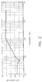
- radial track deviation on an optical disc measured at three locations in FIG. 1, that is at the inner, middle, and outer radius using a Radial Lens Position Sensor (RLPS) while the tracking servo is closed.
- RLPS Radial Lens Position Sensor
- FIG. 1 there are three polar plots of optical discs with different radii, where R is the radius in mm; std is the standard deviation in ⁇ m , and pp is the peak-to-peak dimension in ⁇ m.
- FIG. 2 shows the "disturbance rejection" of a typical tracking servo versus frequency. Given the rotation of the disc and the track shape shown in FIG. 1 at the outer radius, the disturbance tracking frequency is about 100 Hz.
- the rejection of the tracking servo is about 40 dB.
- the tracking servo will reduce the excursion at this frequency by a factor of 100.
- Using a feedforward signal at this frequency can help the tracking servo to better maintain the spot in the center of the track.
- the objective here is to provide a correction signal in anticipation of a disturbance. The anticipation is made possible by the repetitive nature of the runout from one revolution to the next.
- the fundamental principles in using a feedforward for runout compensation are substantially the same for the focus, fine tracking, and radial (coarse) tracking servos.
- the driving signal usually a current signal
- This driving signal is sampled and filtered to extract the repeatable frequency components of interest.
- the filtered drive signal is applied to the target actuator.
- the result of this procedure is the application of a band-limited and repetitive (with each revolution of the media) driving signal to the actuator. In this way, the servo is only required to correct for non-repeatable disturbances to the system.
- many methods of frequency-selective filtering can be applied, including low-, high-, and band-pass filters, and special techniques such as extraction of frequency components via transform methods such as a Fourier transform.
- FIG. 3 is a block diagram of apparatus 10 in accordance with the present invention which provides for tracking and (fine) focusing servo.
- the apparatus 10 includes a focus actuator 12 shown in schematic form.
- the focus actuator 12 has an objective lens 14 which focuses an optical spot onto a surface of an optical disc 16.
- a tracking actuator 13 which, as is well known in the art, positions the objective lens 14 along the track of the disc.
- the focus actuator 12 includes a standard vertical lens position sensor 18 and a standard radial lens position sensor 20. These position sensors are well known in the art and are adapted to produce signals representing the vertical and radial runout of the optical disc 16.
- the actuators 12 and 13 have their own coils for respectively positioning the objective lens 14 in the vertical position and in the radial or tracking position.
- the vertical and radial lens position sensors 18 and 20 are used to determine the position of the objective lens 14 relative to its frame of reference (the locations of the motive force on the actuator).
- the most significant drive signal frequencies to the actuator are determined and used.
- a filtering method is adapted to the frequency content of the runout and a reduced amount of computation is performed. This technique is equally applicable to the focus actuator 12 and the tracking actuator 13. In order to simplify the discussion of the present invention, tracking runout will now be discussed.
- the tracking loop is closed with a carriage 42 at a fixed position.
- the carriage 42 is only shown in block form, but it will be understood to include support rails, bearings, magnets, and coils. Holding the carriage 42 at one position during this procedure (that is, not adjusting its position based on the measured track runout) will result in a large and easily measurable position error signal. This is accomplished by controlling the carriage 42 to a specific radius (using an external carriage position sensor or encoder). Another method is to simply leave the carriage control off, and rely on the inertia of the carriage 42 to effectively "hold” at a radius. This is effective because of the short period of time required to measure the runout.
- the radial lens position sensor 20 is used to obtain a high accuracy measure of the track runout.
- the tracking servo 24 produces the drive current for the tracking actuator 13.
- the radial lens position sensor 20 signal is sampled, and a Fourier series representation is calculated by either a microprocessor or dedicated hardware shown as logic and control unit 26. Either a simple Fourier series or an FFT technique can be used in accordance with the present invention. Although a Fourier transform is preferred, other types of frequency transforms can, of course, be used as will be understood by those skilled in the art. This Fourier series describes the tracking runout in terms of its spatial frequency in multiples of once per revolution.
- the actuator drive signal is stored in a signal processing and storage unit 28.
- the high sampling rate must still be utilized to avoid aliasing effects, but the previously obtained information identifies which harmonics of the once per revolution runout are most significant.
- the selected terms of a Fourier series representation of the actuator drive signal are calculated by the signal processing and storage unit 28.
- a feedforward drive signal is produced by the signal processing and storage unit 28 by performing a reverse Fourier on the selected terms.
- An adder 30 adds the feedforward signal to the tracking actuator current produced by the tracking servo 24.
- the resulting signal is then applied to the actuator tracking coil for controlling the lens in the tracking position.
- the feedforward signal can be further refined by periodically re-measuring the actuator drive signal, finding the selected terms of the Fourier series representation, and averaging them with previous iterations Fourier series representations.
- the feedforward driving signal to the tracking actuator 13 can also be re-synthesized to drive the carriage 42.
- the partition between the carriage 42 and the tracking actuator 13 must be known (that is, how much of the runout to remove with carriage motion, and how much to remove with the tracking actuator).
- the radial lens position sensor's 20 output no longer contains the full information about the track runout (the driving signal to both actuators must now be interrogated).
- Vertical runout is also achieved in a similar fashion to radial runout.
- the vertical position signal produced by vertical lens position sensor 18 is provided to a dedicated logic and control unit 36, which provides the same function as the logic and control unit 26, but on the vertical position signal.
- the signal processing unit 38 which provides the same function as the signal processing and storage unit 28, provides its output signal to an adder 40 which then produces a signal which is applied to the vertical coil of the focus actuator 12 to control the position of the objective lens 14 in the focus position.
- a mathematical model of the actuator can be stored within the signal processing unit. It is used to determine the feedforward drive signal to the actuator from the lens position signal.
- a simple mathematical model of an actuator is generally quite accurate, especially in the frequency range where repeatable runout occurs. This technique is applicable to focus, tracking, and the radial access actuator as described below.
- the tracking loop is closed with the carriage 42 which mounts the focus and tracking actuators 13 and objective lens 14 at a fixed position. This is achieved by the same means as in the first embodiment.
- the radial lens position sensor 20 is used to obtain a high accuracy measure of the track runout.
- the position sensor signal is sampled, and a Fourier series representation is calculated (by either a simple fouries series or an FFT technique).
- a feedforward drive signal transform is developed by dividing the position sensor signal transform by the actuator's open-loop frequency response (calculated or measured). The feed forward signal is then found by performing a reverse transformation on the feed forward drive signal transform.
- the same lens position data used to calculate the feedforward driving signal to the tracking actuator 13 can also be reused to calculate the feedforward drive signal to the carriage 42.
- the designer must be cautious in partitioning between the carriage 42 and the tracking actuator. Since the actuation of the carriage 42 in the same frequency range as the tracking actuator with completely correlated feed forwards dramatically modifies the open-loop transfer function of the tracking actuator. Also note that once the carriage is driven with a feedforward, the position sensor's output no longer contains the full information about the track runout.
Abstract
Description
- The present invention relates to an apparatus for compensating radial and vertical runout of an optical disc.
- In optical data recording, an optical source, typically a laser or laser diode, generates an incident write or read signal in the form of a radiation beam. The beam is applied to an optical medium through a focusing lens to record or read data thereon. To facilitate proper application of the beam to the medium (typically a disc), focusing and tracking servos are used to control vertical and radial positions of the lens by means of an actuator. A focusing servo maintains a focused spot of less than 2 µm on the surface of the medium while a tracking servo maintains the focused spot within preformatted spiral or concentric tracks spaced by less than 5 µm. Certain types of media, such as compact disc recordable (CDR) media, include a performed spiral tracking structure typically referred to as a groove or pregroove having a width of 0.4 µm and spaced by 1.6 µm. Due to changes or tolerances of the manufacturing conditions of optical discs, for example changes in the press force, the disc surface might be distorted (e.g., saddle shape) and the tracks might not be perfectly concentric or spiral. Furthermore, the center hole of the medium, into which the center spindle of the apparatus is inserted, may not be completely concentric, or the shaft of the motor for spinning the medium may not be coaxial with the medium. In addition, disc loading and clamping mechanisms might cause further distortion of the disc shape. Due to such deformations of the disc, well known closed loop focusing and tracking servos become severely challenged, and in some instances may be unable to properly maintain a focused spot in the center of a desired track. As a result, vertical and radial runout sinewave compensation techniques have been described in the literature (see U.S. Patent Nos. US-A-5,121,374 and US-A-4,764,914).
- Known runout compensation techniques consist of storing focus and tracking lens actuator current signals as a function of rotation of the disc. The focus and tracking current signals correspond to vertical excursions of the disc surface and radial eccentricities of the tracks, respectively. Runout correction signals for both focusing and tracking are derived from the actuator current signals and added to the output of the focusing and tracking servos. Typically, a runout signal has a frequency which is the same as the fundamental frequency of the rotation of the disc. It is desirable that the runout signal contains additional frequency components. However, due to the nature of the servo response, the current signal is not optimum for determining which additional frequency components to include.
- It is therefore the object of the present invention to provide an improved runout signal by using a lens position signal (LPS) representing vertical and radial position of the lens.
- It is therefore the object of the present invention to compensate for runout caused by an optical disc or drive.
- This object is achieved in an apparatus for compensating for radial and vertical runout of an optical disc using an actuator having a lens for focus of a laser beam and wherein the focus and tracking currents control the position of the lens in the vertical and radial directions, comprising:
- a) means for focusing the actuator lens along at least one revolution of a track on an optical disc and producing lens position signals;
- b) means responsive to the lens position signals to produce the frequency content of surface height and track deviations of the optical disc using a frequency transform technique;
- c) means for storing such surface height and track deviations frequency content;
- d) means for storing a signal representing the focusing and tracking actuator currents; and
- e) means responsive to the focusing and tracking actuator current signals and the stored surface height and track deviation frequencies to control the lens position and thereby reduce focusing and tracking errors.
- It is a feature of the present invention to provide an effective structure for runout compensation by using vertical and radial lens position sensors representing vertical excursions and radial eccentricities. The lens position signals are used to determine the frequency components required for feedforward compensation.
- FIG. 1 depicts track deviations of polar plots of an optical disc at three different radii;
- FIG. 2 depicts a typical disturbance rejection of a tracking servo without a compensation technique; and
- FIG. 3 is a block diagram of an apparatus in accordance with the present invention.
- As mentioned above, low frequency radial and vertical deviations of optical media (below 500 Hz) challenge the capability of the focusing and tracking servos. Consider, for example, radial track deviation on an optical disc measured at three locations in FIG. 1, that is at the inner, middle, and outer radius using a Radial Lens Position Sensor (RLPS) while the tracking servo is closed. As shown in FIG. 1 there are three polar plots of optical discs with different radii, where R is the radius in mm; std is the standard deviation in µm , and pp is the peak-to-peak dimension in µm. An increase in track distortion is observed across the disc from the inner to the outer radius which is also reflected by the peak-to-peak (pp) and standard deviation (std) of the track deviation from circularity in µm (to the right of the polar plot). The track distortion appears to be largest at the outer diameter with a maximum excursion of 7.3 µm and a dominant frequency that is three times that of the rotation frequency. The tracking servo will insure that the optical spot follows the track, however, due to its finite gain, a residual tracking error will appear, that is, the spot is offset from the center of the track.
- FIG. 2 shows the "disturbance rejection" of a typical tracking servo versus frequency. Given the rotation of the disc and the track shape shown in FIG. 1 at the outer radius, the disturbance tracking frequency is about 100 Hz.
- In FIG. 2, the rejection of the tracking servo is about 40 dB. The tracking servo will reduce the excursion at this frequency by a factor of 100. When the peak-to-peak of the track excursion at the outer diameter is 7 µm, the tracking error is 7/100=0.07 µm or 70 nm, i.e., the optical spot will deviate from the center of the track by 70 nm which is a considerable track offset that might degrade the performance of the overall system. Using a feedforward signal at this frequency can help the tracking servo to better maintain the spot in the center of the track. As with any feedforward application, the objective here is to provide a correction signal in anticipation of a disturbance. The anticipation is made possible by the repetitive nature of the runout from one revolution to the next.
- The fundamental principles in using a feedforward for runout compensation are substantially the same for the focus, fine tracking, and radial (coarse) tracking servos. While the servo system is actively regulating to the desired position, the driving signal (usually a current signal) to the actuator is measured as of function of time (or, equivalently, angular position of the writing surface). This driving signal is sampled and filtered to extract the repeatable frequency components of interest. Finally, the filtered drive signal is applied to the target actuator. The result of this procedure is the application of a band-limited and repetitive (with each revolution of the media) driving signal to the actuator. In this way, the servo is only required to correct for non-repeatable disturbances to the system. Note that many methods of frequency-selective filtering can be applied, including low-, high-, and band-pass filters, and special techniques such as extraction of frequency components via transform methods such as a Fourier transform.
- The common approach to extracting the feed forward drive signal to the actuator is to sample the servo's drive signal directly. However, due to fundamentals of servo design, this signal is substantially wider bandwidth than the repeatable portion of the runout, and therefore is a noisy representation of the actuator drive signal. It is also prone to aliasing effects, unless it is sampled at an exceedingly high rate relative to the repetitive runout. Consequently, a large amount of data must be taken and manipulated to develop the feed forward signals.
- FIG. 3 is a block diagram of
apparatus 10 in accordance with the present invention which provides for tracking and (fine) focusing servo. Theapparatus 10 includes a focus actuator 12 shown in schematic form. As is well understood by those in the art, the focus actuator 12 has anobjective lens 14 which focuses an optical spot onto a surface of anoptical disc 16. In addition, there is atracking actuator 13 which, as is well known in the art, positions theobjective lens 14 along the track of the disc. The focus actuator 12 includes a standard verticallens position sensor 18 and a standard radiallens position sensor 20. These position sensors are well known in the art and are adapted to produce signals representing the vertical and radial runout of theoptical disc 16. Theactuators 12 and 13, of course, have their own coils for respectively positioning theobjective lens 14 in the vertical position and in the radial or tracking position. The actuator currents for the focus and trackingactuators 12 and 13, respectively, control the position of theobjective lens 14. These currents are provided by a focusingcontrol servo 22 and atracking servo 24, respectively. These servos are well known in the art. (See U.S. Patent Nos. US-A-4,866,688 and US-A-4,439,848). - The vertical and radial
lens position sensors objective lens 14 relative to its frame of reference (the locations of the motive force on the actuator). In accordance with this invention, the most significant drive signal frequencies to the actuator are determined and used. Preferably, a filtering method is adapted to the frequency content of the runout and a reduced amount of computation is performed. This technique is equally applicable to the focus actuator 12 and the trackingactuator 13. In order to simplify the discussion of the present invention, tracking runout will now be discussed. - First, during an
optical disc 16 initialization phase, the tracking loop is closed with acarriage 42 at a fixed position. Thecarriage 42 is only shown in block form, but it will be understood to include support rails, bearings, magnets, and coils. Holding thecarriage 42 at one position during this procedure (that is, not adjusting its position based on the measured track runout) will result in a large and easily measurable position error signal. This is accomplished by controlling thecarriage 42 to a specific radius (using an external carriage position sensor or encoder). Another method is to simply leave the carriage control off, and rely on the inertia of thecarriage 42 to effectively "hold" at a radius. This is effective because of the short period of time required to measure the runout. As the trackingservo 24 follows the track (with thecarriage 42 at a fixed position), the radiallens position sensor 20 is used to obtain a high accuracy measure of the track runout. The trackingservo 24 produces the drive current for the trackingactuator 13. The radiallens position sensor 20 signal is sampled, and a Fourier series representation is calculated by either a microprocessor or dedicated hardware shown as logic andcontrol unit 26. Either a simple Fourier series or an FFT technique can be used in accordance with the present invention. Although a Fourier transform is preferred, other types of frequency transforms can, of course, be used as will be understood by those skilled in the art. This Fourier series describes the tracking runout in terms of its spatial frequency in multiples of once per revolution. By inspecting the Fourier series, the largest and therefore most significant harmonics are identified. A subset of harmonics are thereby chosen to be represented in the feed forward signal based on their relative amplitudes. This process can be repeated by the logic andcontrol unit 26 at a plurality of radii, if the media is capable of exhibiting a different runout characteristic as a function of radius. - While the tracking
actuator 13 is in normal operation, and the trackingservo 24 and optionally thecarriage 42 following servo are on, the actuator drive signal is stored in a signal processing andstorage unit 28. The high sampling rate must still be utilized to avoid aliasing effects, but the previously obtained information identifies which harmonics of the once per revolution runout are most significant. Using this information, the selected terms of a Fourier series representation of the actuator drive signal, are calculated by the signal processing andstorage unit 28. Then a feedforward drive signal is produced by the signal processing andstorage unit 28 by performing a reverse Fourier on the selected terms. Anadder 30 adds the feedforward signal to the tracking actuator current produced by the trackingservo 24. The resulting signal is then applied to the actuator tracking coil for controlling the lens in the tracking position. The feedforward signal can be further refined by periodically re-measuring the actuator drive signal, finding the selected terms of the Fourier series representation, and averaging them with previous iterations Fourier series representations. - Note that the feedforward driving signal to the tracking
actuator 13 can also be re-synthesized to drive thecarriage 42. However, the partition between thecarriage 42 and the trackingactuator 13 must be known (that is, how much of the runout to remove with carriage motion, and how much to remove with the tracking actuator). Also note that once thecarriage 42 is driven with a feedforward, the radial lens position sensor's 20 output no longer contains the full information about the track runout (the driving signal to both actuators must now be interrogated). - Vertical runout is also achieved in a similar fashion to radial runout. For example, the vertical position signal produced by vertical
lens position sensor 18 is provided to a dedicated logic andcontrol unit 36, which provides the same function as the logic andcontrol unit 26, but on the vertical position signal. Thesignal processing unit 38, which provides the same function as the signal processing andstorage unit 28, provides its output signal to anadder 40 which then produces a signal which is applied to the vertical coil of the focus actuator 12 to control the position of theobjective lens 14 in the focus position. - Although radial and vertical runout can be separately provided, it is highly advantageous to use the present invention with both focus and tracking control.
- In another embodiment, a mathematical model of the actuator can be stored within the signal processing unit. It is used to determine the feedforward drive signal to the actuator from the lens position signal. A simple mathematical model of an actuator is generally quite accurate, especially in the frequency range where repeatable runout occurs. This technique is applicable to focus, tracking, and the radial access actuator as described below.
- The tracking loop is closed with the
carriage 42 which mounts the focus and trackingactuators 13 andobjective lens 14 at a fixed position. This is achieved by the same means as in the first embodiment. As the trackingactuator 13 follows the track (with thecarriage 42 at a fixed position), the radiallens position sensor 20 is used to obtain a high accuracy measure of the track runout. The position sensor signal is sampled, and a Fourier series representation is calculated (by either a simple fouries series or an FFT technique). A feedforward drive signal transform is developed by dividing the position sensor signal transform by the actuator's open-loop frequency response (calculated or measured). The feed forward signal is then found by performing a reverse transformation on the feed forward drive signal transform. - Similar to the first embodiment, the same lens position data used to calculate the feedforward driving signal to the tracking
actuator 13 can also be reused to calculate the feedforward drive signal to thecarriage 42. However, the designer must be cautious in partitioning between thecarriage 42 and the tracking actuator. Since the actuation of thecarriage 42 in the same frequency range as the tracking actuator with completely correlated feed forwards dramatically modifies the open-loop transfer function of the tracking actuator. Also note that once the carriage is driven with a feedforward, the position sensor's output no longer contains the full information about the track runout.
Claims (9)
- Apparatus for compensating for radial and vertical runout of an optical disc using an actuator having a lens for focus of a laser beam and wherein the focus and tracking currents control the position of the lens in the vertical and radial directions, respectively, comprising:a) means for focusing the actuator lens along at least one revolution of a track on an optical disc and producing lens position signals;b) means responsive to the lens position signals to produce the frequency content of surface height and track deviations of the optical disc using a frequency transform technique;c) means for storing such surface height and track deviations frequency content;d) means for storing a signal representing the focusing and tracking actuator currents; ande) means responsive to the focusing and tracking actuator current signals and the stored surface height and track deviation frequencies to control the lens position and thereby reduce focusing and tracking errors.
- Apparatus for compensating for vertical runout of an optical disc using an actuator having a lens for focus of a laser beam and wherein the focus current controls the position of the actuator lens in a focus direction, comprising:a) means for focusing the actuator lens along at least one revolution of a track on an optical disc and for producing a vertical lens position signal;b) means responsive to the vertical lens position signal to produce the frequency content of surface height deviations of the optical disc;c) means for storing such surface height frequency content;d) means for storing a signal representing the focusing actuator current;e) means responsive to the focusing actuator current signal and the stored surface height frequency components to produce a feedforward current; andf) means for adding the feedforward current to the focusing actuator current to control the focusing actuator thereby reducing focusing error.
- Apparatus as set forth in claim 2 wherein tracking current controls the position of the lens in a tracking direction and including a radial tracking actuator and including:g) means for tracking the actuator lens along at least one revolution of a track on an optical disc and for producing a radial lens position signal;h) means responsive to the radial lens position signal to produce the frequency content of track deviations of the optical disc;i) means for storing such tracking deviation frequency content;j) means for storing a signal representing the actuator tracking current;k) means responsive to the tracking actuator current signal and to the stored track deviation frequency components to produce a feedforward current; andl) means for adding the feedforward current to the tracking actuator current to control the tracking actuator thereby reducing tracking error.
- Apparatus for compensating for vertical runout of an optical disc using an actuator having a lens for focus of a laser beam and wherein the focus current controls the position of the actuator lens in a focus direction, comprising:a) means for focusing the actuator lens along at least one revolution of a track on an optical disc and for producing a vertical lens position signal;b) means responsive to the vertical lens position signal to produce the frequency content of surface height deviations of the optical disc;c) means for storing such surface height frequency content; andd) means responsive to a stored open-loop focusing-actuator frequency response and the stored surface height frequency components to produce a feedforward current.
- Apparatus as set forth in claim 4 wherein tracking current controls the position of the lens in a tracking direction and including a radial tracking actuator and including:e) means for tracking the actuator lens along at least one revolution of a track on an optical disc and for producing a radial lens position signal;f) means responsive to the radial lens position signal to produce the frequency content of track deviations of the optical disc;g) means for storing such tracking deviation frequency content;h) means responsive to a stored open-loop tracking-actuator frequency response and the stored track deviation frequency components to produce a feedforward current.
- Apparatus for compensating for radial runout of an optical disc using an actuator having a lens for focus of a laser beam, comprising:a) means for tracking the actuator lens along at least one revolution of a track on an optical disc and for producing a radial lens position signal;b) means responsive to the radial lens position signal to produce frequency content of track deviations of the optical disc;c) means for storing such tracking deviation frequency content;d) means for storing a signal representing the actuator tracking current;e) means responsive to the tracking actuator current signal and to the stored track deviation frequency components to produce a feedforward current; andf) means for adding the feedforward current to the tracking actuator current to control the tracking actuator thereby reducing error.
- The apparatus as set forth in claim 6 wherein the actuator tracking current signal is provided by a stored model of actuator tracking current.
- Apparatus as set forth in claim 6 wherein tracking current controls the position of the lens in a tracking direction and including a radial tracking actuator and including:g) means for tracking the actuator lens along at least one revolution of a track on an optical disc and for producing a radial lens position signal;h) means responsive to the radial lens position signal to produce the frequency content of track deviations of the optical disc;i) means for storing such tracking deviation frequency content;j) means for storing a signal representing the carriage current;k) means responsive to the carriage current signal and to the stored track deviation frequency components to produce a feedforward current; andl) means for adding the feedforward current to the carriage current to control the carriage thereby reducing tracking error.
- The apparatus as set forth in claim 1 wherein tracking current controls the position of the lens in a tracking direction and including a radial tracking actuator.
Applications Claiming Priority (2)
| Application Number | Priority Date | Filing Date | Title |
|---|---|---|---|
| US642385 | 1996-05-03 | ||
| US08/642,385 US5742573A (en) | 1996-05-03 | 1996-05-03 | Compensation apparatus for radial and vertical runout of an optical disc |
Publications (2)
| Publication Number | Publication Date |
|---|---|
| EP0805439A1 true EP0805439A1 (en) | 1997-11-05 |
| EP0805439B1 EP0805439B1 (en) | 2002-01-30 |
Family
ID=24576328
Family Applications (1)
| Application Number | Title | Priority Date | Filing Date |
|---|---|---|---|
| EP97201160A Expired - Lifetime EP0805439B1 (en) | 1996-05-03 | 1997-04-21 | Compensation for radial and vertical runout of an optical disc |
Country Status (4)
| Country | Link |
|---|---|
| US (1) | US5742573A (en) |
| EP (1) | EP0805439B1 (en) |
| JP (1) | JPH1031831A (en) |
| DE (1) | DE69710119T2 (en) |
Cited By (5)
| Publication number | Priority date | Publication date | Assignee | Title |
|---|---|---|---|---|
| SG79960A1 (en) * | 1998-02-02 | 2001-04-17 | Texas Instr Singapore Pte Ltd | Using radial runout to calibrate radial actuator frequency response in a cd/dvd pickup |
| SG79958A1 (en) * | 1998-02-02 | 2001-04-17 | Texas Instr Singapore Pte Ltd | Cd/dvd radial runout calibration |
| EP1253587A2 (en) * | 2001-04-24 | 2002-10-30 | Kabushiki Kaisha Toshiba | Optical disk apparatus and optical disk processing method |
| KR20050027031A (en) * | 2003-09-12 | 2005-03-17 | 휴렛-팩커드 디벨롭먼트 컴퍼니, 엘 피 | Optical disk drive focusing apparatus |
| WO2005034106A2 (en) * | 2003-09-12 | 2005-04-14 | Hewlett-Packard Development Company, L.P. | Optical disk drive focusing apparatus |
Families Citing this family (5)
| Publication number | Priority date | Publication date | Assignee | Title |
|---|---|---|---|---|
| JPH10208418A (en) * | 1997-01-17 | 1998-08-07 | Alps Electric Co Ltd | Apparatus for controlling track-tracking |
| US6590843B1 (en) * | 1998-06-02 | 2003-07-08 | Texas Instruments Incorporated | DVD radial runout cancellation with self-calibration |
| US6728178B2 (en) * | 2000-10-27 | 2004-04-27 | Matsushita Electric Industrial Co., Ltd. | Semiconductor laser control method and semiconductor laser control device |
| JP2003030867A (en) * | 2001-07-13 | 2003-01-31 | Hitachi Ltd | Focus control method, focus controller and master disk exposure device using this controller |
| US20080049571A1 (en) * | 2006-08-25 | 2008-02-28 | Mediatek, Inc. | Method and apparatus for compensating periodic signal |
Citations (6)
| Publication number | Priority date | Publication date | Assignee | Title |
|---|---|---|---|---|
| US4616276A (en) * | 1985-07-16 | 1986-10-07 | International Business Machines Corporation | Disk file servo control system with fast reduction of repeatable head position error |
| US4628379A (en) * | 1984-09-25 | 1986-12-09 | Amcodyne Incorporated | Disk runout compensator |
| JPS6371608A (en) * | 1986-09-12 | 1988-04-01 | Seiko Epson Corp | Eccentricity measuring instrument |
| US4764914A (en) * | 1987-09-11 | 1988-08-16 | Eastman Kodak Company | Least squares method and apparatus for determining track eccentricity of a disk |
| US5121374A (en) * | 1989-10-25 | 1992-06-09 | Eastman Kodak Company | Method for automatically compensating for the eccentricity in an optical head positioning servo-mechanism |
| JPH06349078A (en) * | 1993-06-07 | 1994-12-22 | Ricoh Co Ltd | Tracking servo system for optical disk driving device |
Family Cites Families (5)
| Publication number | Priority date | Publication date | Assignee | Title |
|---|---|---|---|---|
| US3881184A (en) * | 1974-05-28 | 1975-04-29 | Ibm | Adaptive digital servo system |
| US4439848A (en) * | 1978-03-27 | 1984-03-27 | Discovision Associates | Focusing system for video disc player |
| US4866688A (en) * | 1985-12-20 | 1989-09-12 | Hitachi, Ltd. | Composite tracking servo system for optical disc apparatus with track offset correction |
| JPH0721868B2 (en) * | 1989-08-04 | 1995-03-08 | キヤノン株式会社 | Optical information processing device |
| WO1993006595A1 (en) * | 1991-09-25 | 1993-04-01 | Integral Peripherals, Inc. | Adaptive runout compensation for miniature disk drives |
-
1996
- 1996-05-03 US US08/642,385 patent/US5742573A/en not_active Expired - Fee Related
-
1997
- 1997-04-15 JP JP9097438A patent/JPH1031831A/en active Pending
- 1997-04-21 EP EP97201160A patent/EP0805439B1/en not_active Expired - Lifetime
- 1997-04-21 DE DE69710119T patent/DE69710119T2/en not_active Expired - Lifetime
Patent Citations (6)
| Publication number | Priority date | Publication date | Assignee | Title |
|---|---|---|---|---|
| US4628379A (en) * | 1984-09-25 | 1986-12-09 | Amcodyne Incorporated | Disk runout compensator |
| US4616276A (en) * | 1985-07-16 | 1986-10-07 | International Business Machines Corporation | Disk file servo control system with fast reduction of repeatable head position error |
| JPS6371608A (en) * | 1986-09-12 | 1988-04-01 | Seiko Epson Corp | Eccentricity measuring instrument |
| US4764914A (en) * | 1987-09-11 | 1988-08-16 | Eastman Kodak Company | Least squares method and apparatus for determining track eccentricity of a disk |
| US5121374A (en) * | 1989-10-25 | 1992-06-09 | Eastman Kodak Company | Method for automatically compensating for the eccentricity in an optical head positioning servo-mechanism |
| JPH06349078A (en) * | 1993-06-07 | 1994-12-22 | Ricoh Co Ltd | Tracking servo system for optical disk driving device |
Non-Patent Citations (3)
| Title |
|---|
| "runout compensator for disk file", IBM TDB, vol. 31, no. 8, January 1989 (1989-01-01), ARMONK, NY, USA, pages 453 - 454, XP000023970 * |
| PATENT ABSTRACTS OF JAPAN vol. 012, no. 298 (P - 744) 15 August 1988 (1988-08-15) * |
| PATENT ABSTRACTS OF JAPAN vol. 095, no. 003 28 April 1995 (1995-04-28) * |
Cited By (12)
| Publication number | Priority date | Publication date | Assignee | Title |
|---|---|---|---|---|
| SG79960A1 (en) * | 1998-02-02 | 2001-04-17 | Texas Instr Singapore Pte Ltd | Using radial runout to calibrate radial actuator frequency response in a cd/dvd pickup |
| SG79958A1 (en) * | 1998-02-02 | 2001-04-17 | Texas Instr Singapore Pte Ltd | Cd/dvd radial runout calibration |
| EP1253587A2 (en) * | 2001-04-24 | 2002-10-30 | Kabushiki Kaisha Toshiba | Optical disk apparatus and optical disk processing method |
| US6829203B2 (en) | 2001-04-24 | 2004-12-07 | Kabushiki Kaisha Toshiba | Optical disk apparatus and optical disk processing method |
| EP1253587A3 (en) * | 2001-04-24 | 2004-12-15 | Kabushiki Kaisha Toshiba | Optical disk apparatus and optical disk processing method |
| US7133343B2 (en) | 2001-04-24 | 2006-11-07 | Kabushiki Kaisha Toshiba | Optical disk apparatus and optical disk processing method |
| KR20050027031A (en) * | 2003-09-12 | 2005-03-17 | 휴렛-팩커드 디벨롭먼트 컴퍼니, 엘 피 | Optical disk drive focusing apparatus |
| EP1517314A2 (en) | 2003-09-12 | 2005-03-23 | Hewlett-Packard Development Company, L.P. | Optical disk drive focusing apparatus |
| WO2005034106A2 (en) * | 2003-09-12 | 2005-04-14 | Hewlett-Packard Development Company, L.P. | Optical disk drive focusing apparatus |
| WO2005034106A3 (en) * | 2003-09-12 | 2005-06-16 | Hewlett Packard Development Co | Optical disk drive focusing apparatus |
| US7177246B2 (en) | 2003-09-12 | 2007-02-13 | Hewlett-Packard Development Company, L.P. | Optical disk drive focusing apparatus using sum signal |
| EP1517314A3 (en) * | 2003-09-12 | 2007-10-03 | Hewlett-Packard Development Company, L.P. | Optical disk drive focusing apparatus |
Also Published As
| Publication number | Publication date |
|---|---|
| DE69710119T2 (en) | 2002-09-19 |
| US5742573A (en) | 1998-04-21 |
| JPH1031831A (en) | 1998-02-03 |
| DE69710119D1 (en) | 2002-03-14 |
| EP0805439B1 (en) | 2002-01-30 |
Similar Documents
| Publication | Publication Date | Title |
|---|---|---|
| US5479388A (en) | Servo control system for head recording and/or reproducing information on and/or from recording medium | |
| US6310742B1 (en) | Repeatable runout cancellation in sectored servo disk drive positioning system | |
| KR0178510B1 (en) | Single stage track seek method and lens assembly control circuit | |
| EP0805439B1 (en) | Compensation for radial and vertical runout of an optical disc | |
| JP3834786B2 (en) | Servo control and coarse actuator | |
| JP3559209B2 (en) | Storage device | |
| US4918680A (en) | Focus-servo correction utilizing storage of detected focus errors | |
| US5210732A (en) | Optical disk apparatus | |
| US20070274166A1 (en) | Optical disc drive | |
| US5742568A (en) | Tracking controller and seek controller for optical recording device | |
| JPH0877589A (en) | Optical disk device | |
| JP3642720B2 (en) | Storage device, tracking control method and tracking control device thereof | |
| US5260923A (en) | Optical information processing apparatus in which an optical head is moved in accordance with a lens positional signal eliminating an eccentric component therefrom | |
| JP4550764B2 (en) | SEEK CONTROL METHOD, SEEK CONTROL DEVICE, AND DISC DEVICE | |
| KR20070044044A (en) | Method and device for tilt compensation in an optical storage system | |
| US6970321B2 (en) | Automatic model regulation in a disc drive servo system using model reference inverse | |
| US4718051A (en) | Optical beam tracking system for use in optical information recording and/or reproducing apparatus | |
| KR20010042394A (en) | Optical scanning device with parallel-controlled actuators | |
| US20080316877A1 (en) | Control Method for an Optical Drive with Different Bandwidths | |
| US6414815B1 (en) | Apparatus and method for controlling on-track operation of an actuator in a hard disk drive | |
| JP2774295B2 (en) | Optical information recording / reproducing device | |
| JP2002358678A (en) | Track servo control method, track servo controller, and optical storage device | |
| KR100728012B1 (en) | Tilt compensation method and tilt compensation apparatus | |
| JPH08321047A (en) | Track access device | |
| JP2000173081A (en) | Disk apparatus and driving method for head of disk apparatus |
Legal Events
| Date | Code | Title | Description |
|---|---|---|---|
| PUAI | Public reference made under article 153(3) epc to a published international application that has entered the european phase |
Free format text: ORIGINAL CODE: 0009012 |
|
| AK | Designated contracting states |
Kind code of ref document: A1 Designated state(s): DE FR GB |
|
| 17P | Request for examination filed |
Effective date: 19980504 |
|
| 17Q | First examination report despatched |
Effective date: 19981230 |
|
| GRAG | Despatch of communication of intention to grant |
Free format text: ORIGINAL CODE: EPIDOS AGRA |
|
| GRAG | Despatch of communication of intention to grant |
Free format text: ORIGINAL CODE: EPIDOS AGRA |
|
| GRAH | Despatch of communication of intention to grant a patent |
Free format text: ORIGINAL CODE: EPIDOS IGRA |
|
| GRAH | Despatch of communication of intention to grant a patent |
Free format text: ORIGINAL CODE: EPIDOS IGRA |
|
| GRAA | (expected) grant |
Free format text: ORIGINAL CODE: 0009210 |
|
| REG | Reference to a national code |
Ref country code: GB Ref legal event code: IF02 |
|
| AK | Designated contracting states |
Kind code of ref document: B1 Designated state(s): DE FR GB |
|
| REF | Corresponds to: |
Ref document number: 69710119 Country of ref document: DE Date of ref document: 20020314 |
|
| ET | Fr: translation filed | ||
| PLBE | No opposition filed within time limit |
Free format text: ORIGINAL CODE: 0009261 |
|
| STAA | Information on the status of an ep patent application or granted ep patent |
Free format text: STATUS: NO OPPOSITION FILED WITHIN TIME LIMIT |
|
| 26N | No opposition filed | ||
| PGFP | Annual fee paid to national office [announced via postgrant information from national office to epo] |
Ref country code: GB Payment date: 20050314 Year of fee payment: 9 |
|
| PGFP | Annual fee paid to national office [announced via postgrant information from national office to epo] |
Ref country code: FR Payment date: 20050401 Year of fee payment: 9 |
|
| PGFP | Annual fee paid to national office [announced via postgrant information from national office to epo] |
Ref country code: DE Payment date: 20050429 Year of fee payment: 9 |
|
| PG25 | Lapsed in a contracting state [announced via postgrant information from national office to epo] |
Ref country code: DE Free format text: LAPSE BECAUSE OF THE APPLICANT RENOUNCES Effective date: 20060221 |
|
| PG25 | Lapsed in a contracting state [announced via postgrant information from national office to epo] |
Ref country code: GB Free format text: LAPSE BECAUSE OF NON-PAYMENT OF DUE FEES Effective date: 20060421 |
|
| GBPC | Gb: european patent ceased through non-payment of renewal fee |
Effective date: 20060421 |
|
| REG | Reference to a national code |
Ref country code: FR Ref legal event code: ST Effective date: 20061230 |
|
| PG25 | Lapsed in a contracting state [announced via postgrant information from national office to epo] |
Ref country code: FR Free format text: LAPSE BECAUSE OF NON-PAYMENT OF DUE FEES Effective date: 20060502 |