EP0798704A1 - Sliding mode control of an optical disc drive actuator - Google Patents
Sliding mode control of an optical disc drive actuator Download PDFInfo
- Publication number
- EP0798704A1 EP0798704A1 EP97301834A EP97301834A EP0798704A1 EP 0798704 A1 EP0798704 A1 EP 0798704A1 EP 97301834 A EP97301834 A EP 97301834A EP 97301834 A EP97301834 A EP 97301834A EP 0798704 A1 EP0798704 A1 EP 0798704A1
- Authority
- EP
- European Patent Office
- Prior art keywords
- phase state
- signal
- phase
- optical disc
- state signal
- Prior art date
- Legal status (The legal status is an assumption and is not a legal conclusion. Google has not performed a legal analysis and makes no representation as to the accuracy of the status listed.)
- Withdrawn
Links
- 230000003287 optical effect Effects 0.000 title claims abstract description 104
- 230000001133 acceleration Effects 0.000 claims description 21
- 230000004044 response Effects 0.000 claims description 20
- 238000000034 method Methods 0.000 claims description 8
- 230000008859 change Effects 0.000 claims description 6
- 230000000694 effects Effects 0.000 claims description 4
- 230000001052 transient effect Effects 0.000 abstract description 6
- 230000006870 function Effects 0.000 description 10
- 230000002441 reversible effect Effects 0.000 description 10
- 238000010586 diagram Methods 0.000 description 5
- 230000003044 adaptive effect Effects 0.000 description 4
- 230000004048 modification Effects 0.000 description 3
- 238000012986 modification Methods 0.000 description 3
- 230000010287 polarization Effects 0.000 description 3
- 230000009471 action Effects 0.000 description 2
- 230000008878 coupling Effects 0.000 description 2
- 238000010168 coupling process Methods 0.000 description 2
- 238000005859 coupling reaction Methods 0.000 description 2
- 230000003247 decreasing effect Effects 0.000 description 2
- 238000001914 filtration Methods 0.000 description 2
- 238000009499 grossing Methods 0.000 description 2
- 230000010354 integration Effects 0.000 description 2
- 230000008569 process Effects 0.000 description 2
- 230000009467 reduction Effects 0.000 description 2
- 230000002829 reductive effect Effects 0.000 description 2
- 230000007704 transition Effects 0.000 description 2
- 230000002238 attenuated effect Effects 0.000 description 1
- 238000004883 computer application Methods 0.000 description 1
- 238000011109 contamination Methods 0.000 description 1
- 238000013016 damping Methods 0.000 description 1
- 230000007423 decrease Effects 0.000 description 1
- 238000009795 derivation Methods 0.000 description 1
- 238000001514 detection method Methods 0.000 description 1
- 230000006872 improvement Effects 0.000 description 1
- 230000000670 limiting effect Effects 0.000 description 1
- 230000010355 oscillation Effects 0.000 description 1
- 230000035945 sensitivity Effects 0.000 description 1
- 238000004088 simulation Methods 0.000 description 1
Images


Classifications
-
- G—PHYSICS
- G11—INFORMATION STORAGE
- G11B—INFORMATION STORAGE BASED ON RELATIVE MOVEMENT BETWEEN RECORD CARRIER AND TRANSDUCER
- G11B7/00—Recording or reproducing by optical means, e.g. recording using a thermal beam of optical radiation by modifying optical properties or the physical structure, reproducing using an optical beam at lower power by sensing optical properties; Record carriers therefor
- G11B7/08—Disposition or mounting of heads or light sources relatively to record carriers
- G11B7/09—Disposition or mounting of heads or light sources relatively to record carriers with provision for moving the light beam or focus plane for the purpose of maintaining alignment of the light beam relative to the record carrier during transducing operation, e.g. to compensate for surface irregularities of the latter or for track following
- G11B7/0946—Disposition or mounting of heads or light sources relatively to record carriers with provision for moving the light beam or focus plane for the purpose of maintaining alignment of the light beam relative to the record carrier during transducing operation, e.g. to compensate for surface irregularities of the latter or for track following specially adapted for operation during external perturbations not related to the carrier or servo beam, e.g. vibration
-
- G—PHYSICS
- G05—CONTROLLING; REGULATING
- G05B—CONTROL OR REGULATING SYSTEMS IN GENERAL; FUNCTIONAL ELEMENTS OF SUCH SYSTEMS; MONITORING OR TESTING ARRANGEMENTS FOR SUCH SYSTEMS OR ELEMENTS
- G05B13/00—Adaptive control systems, i.e. systems automatically adjusting themselves to have a performance which is optimum according to some preassigned criterion
- G05B13/02—Adaptive control systems, i.e. systems automatically adjusting themselves to have a performance which is optimum according to some preassigned criterion electric
- G05B13/0205—Adaptive control systems, i.e. systems automatically adjusting themselves to have a performance which is optimum according to some preassigned criterion electric not using a model or a simulator of the controlled system
- G05B13/0255—Adaptive control systems, i.e. systems automatically adjusting themselves to have a performance which is optimum according to some preassigned criterion electric not using a model or a simulator of the controlled system the criterion being a time-optimal performance criterion
-
- G—PHYSICS
- G11—INFORMATION STORAGE
- G11B—INFORMATION STORAGE BASED ON RELATIVE MOVEMENT BETWEEN RECORD CARRIER AND TRANSDUCER
- G11B7/00—Recording or reproducing by optical means, e.g. recording using a thermal beam of optical radiation by modifying optical properties or the physical structure, reproducing using an optical beam at lower power by sensing optical properties; Record carriers therefor
- G11B7/08—Disposition or mounting of heads or light sources relatively to record carriers
- G11B7/085—Disposition or mounting of heads or light sources relatively to record carriers with provision for moving the light beam into, or out of, its operative position or across tracks, otherwise than during the transducing operation, e.g. for adjustment or preliminary positioning or track change or selection
- G11B7/08505—Methods for track change, selection or preliminary positioning by moving the head
- G11B7/08529—Methods and circuits to control the velocity of the head as it traverses the tracks
-
- G—PHYSICS
- G11—INFORMATION STORAGE
- G11B—INFORMATION STORAGE BASED ON RELATIVE MOVEMENT BETWEEN RECORD CARRIER AND TRANSDUCER
- G11B7/00—Recording or reproducing by optical means, e.g. recording using a thermal beam of optical radiation by modifying optical properties or the physical structure, reproducing using an optical beam at lower power by sensing optical properties; Record carriers therefor
- G11B7/08—Disposition or mounting of heads or light sources relatively to record carriers
- G11B7/09—Disposition or mounting of heads or light sources relatively to record carriers with provision for moving the light beam or focus plane for the purpose of maintaining alignment of the light beam relative to the record carrier during transducing operation, e.g. to compensate for surface irregularities of the latter or for track following
- G11B7/0908—Disposition or mounting of heads or light sources relatively to record carriers with provision for moving the light beam or focus plane for the purpose of maintaining alignment of the light beam relative to the record carrier during transducing operation, e.g. to compensate for surface irregularities of the latter or for track following for focusing only
Definitions
- the present invention relates to optical storage systems, particularly to controlling the read head actuator in an optical disc drive.
- Optical disc drives such as CD-ROMs, are commonly used for storing large amounts of digital data on a single disc for use in audio/video or computer applications, and the like.
- the data on an optical disc is typically recorded as a series of "pits" arranged in tracks, where the length of the pit determines the presence of a digital "0" bit or a "1" bit.
- a servo system focuses a laser beam onto the surface of the disc such that the characteristics of the reflected beam allow detection of the data pits.
- the servo system performs four operations: (1) a capture operation to "pull-in" the initial focus position, (2) a seek operation to move the beam to a desired track, (3) a centerline tracking operation to maintain the beam over the centerline of the selected track while reading the recorded data, and (4) a focus tracking operation to maintain proper focus as the disc spins over the beam.
- FIG. 1A illustrates a typical three beam optical head assembly, the operation of which is well known by those skilled in the art.
- a laser diode 1 produces a light beam which passes through a diffraction grating (not shown) splitting the main beam into three separate beams 2 (a center beam and two side beams); the three beams 2 then pass through a polarization beam splitter 3 and a collimator lens (not shown).
- the light beams 2 are then reflected by a prism 4 , through an object lens (OL) 5 , and onto the surface of the optical disc (not shown).
- OL object lens
- the beams 2 reflect off the optical disc, again pass through the OL 5 , and then reflect off the prism 4 back toward the polarization prism 3 .
- the polarization prism 3 deflects the center beam onto a quadrant photodetector 6 , and deflects the two side beams onto two tracking photodiodes ( 7A,7B ).
- the quadrant photodetector 6 generates a focus error signal (FES) for focusing the OL 5 , and it generates an RF read signal for reading the recorded data.
- the tracking photodiodes ( 7A,7B ) generate a tracking error signal (TES) used to maintain the position of the OL 5 over the centerline of a selected track while reading data from the disc.
- TES tracking error signal
- the entire sled assembly 8 slides radially along a lead screw 9 underneath the optical disc until the read head is positioned near the desired track.
- This coarse positioning is accomplished by rotating the lead screw 9 in a clockwise or counterclockwise direction.
- OL voice coil motors VCMs
- 10A,10B rotate an OL carriage unit 11 about a plastic hinge 12 in a "fine seeking" operation until the OL 5 is positioned directly over the desired track.
- the OL VCMs ( 10A,10B ) perform fine adjustments in a "tracking" operation in order to maintain the position of the OL 5 over the centerline of the selected track as information is read from the disc.
- the OL VCMs ( 10A,10B ) can rotate the OL carriage unit 11 , and thereby the OL 5 , about the plastic hinge 12 in a range that spans approximately 200 tracks on either side of its center position.
- the OL carriage unit 11 can perform the entire seek operation without needing to slide the sled assembly 8 along the lead screw 9 .
- the lead screw 9 slowly slides the sled assembly 8 toward the selected track until the OL carriage unit 11 is again in its center position.
- the OL VCMs ( 10A,10B ) also move the OL carriage unit 11 up and down in the direction shown in order to "capture" and "track” the OL 5 focus position.
- the quadrant photodetector 6 For focus capture and focus tracking the quadrant photodetector 6 generates an astigmatic focus error signal indicative of the distance between the OL 5 and the optical disc.
- the OL carriage unit 1 is initially positioned sufficiently away from the disc so that it is out-of-focus. Then the OL VCMs ( 10A,10B ) slowly move the OL carriage unit 11 toward the disc with the focus servo loop open until the quadrant photodetector 6 indicates that the OL 5 is within its focus pull-in range.
- the focus servo loop is closed and the initial focus point is captured. Thereafter, the OL VCMs ( 10A,10B ) track the in-focus position in response to the astigmatic focus error signal (FES) as the read head seeks to selected tracks and reads data from the disc.
- FES astigmatic focus error signal
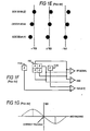
- FIG. 1B illustrates how the changing image on the quadrant photodetector 6 generates the focus error signal (FES).
- FES focus error signal
- FIG. 1C is a plot of the focus error signal (FES) versus the distance between the OL 5 and the optical disc, where the linear region defines the focus "pull-in" range for the focus capture operation.
- FIG. 1E shows how the tracking photodiodes ( 7A,7B ) generate the tracking error signal (TES) according to the intensity of the side beams.
- the tracking error signal When positioned perfectly over the track's centerline, the tracking error signal is zero.
- the tracking error signal (TES) is positive or negative, respectively.
- the tracking error signal (TES) is generated as (E-F) as illustrated by FIG. 1F.
- FIG. 1G is a plot of the tracking error signal (TES) versus the mistracking, where the linear region indicates the pull-in region for the tracking operation.
- Still another problem is maintaining focus during seek operations which presents a significant external disturbance to the focus servo loop. If the focus is lost during a seek, the storage system must pause to perform a focus capture operation which can significantly increase the seek time.
- Conventional servo systems found in optical storage systems typically implement a linear controller using Proportional-Integral-Derivative (PID) feedback and/or state estimators.
- PID Proportional-Integral-Derivative
- Conventional adaptive linear controllers overcome this sensitivity problem by executing complex calibration routines or by continuously re-programming the controller to compensate for the parameter variations and load disturbances.
- adaptive linear controllers are complex and may require notch filters for filtering out mechanical resonances.
- conventional linear controllers are not adept to the above described problems inherent in controlling an actuator for an optical disc drive.
- An optical disc storage system comprises a sliding mode controller for actuating an optical read head assembly over an optical disc during focus capture, focus tracking, track seeking and centerline tracking.
- the sliding mode controller is a nonlinear control system which operates by switching between positive and negative feedback in order to force certain phase states (such as the read head's position error and velocity) to follow a predetermined phase state trajectory.
- phase states such as the read head's position error and velocity
- the positive and negative feedback gains need only be within a predetermined range, thereby allowing gain values of 2 n which significantly reduces the complexity and cost of the gain multipliers.
- the resulting servo control system overcomes many of the inherent difficulties in actuating an optical read head, and at a much lower cost than conventional adaptive linear controllers. Specifically, it provides robust compensation for parametric variations that can occur due to such factors as temperature and voltage drift and parametric variations that occur between individual disc drives. Furthermore, sliding mode control better compensates for transients caused by external load disturbances as well as the transient associated with closing the servo loop during focus capture. Still further, sliding mode control provides a less complex solution to the above mentioned optical coupling between the focus tracking and centerline tracking servo loops.
- the invention provides an optical disc drive storage system for recording digital data, comprising:
- the phase state generator may comprise a state estimator.
- the sliding mode controller may operate in a seek mode to move the read head from a current track to a selected track; in a tracking mode to maintain the read head over a centerline of a selected track; and in a focus mode to maintain the read head in a focus position over the disc.
- the optical disc drive storage system comprises at least two phase states; the sliding mode controller switches between a first and a second structure; the first structure causes the two phase states to change relative to a phase plane to follow a first phase trajectory; the second structure causes the two phase states to change relative to the phase plane to follow a second phase trajectory; the first and second phase trajectories intercept in opposite directions in at least part of the phase plane; and by switching between the first and second structures the sliding mode controller causes the two phase states to change relative to the phase plane to substantially follow a predetermined third phase trajectory.
- the optical disc drive storage system may further comprise switching logic, responsive to the at least one phase state signal, for controlling the switching between the first and second structures.
- the invention also provides a method for controlling the motion of an optical read head positioned over a rotating optical disc storage medium, the optical disc comprises a plurality of data tracks recorded thereon, a motor actuates the read head over the optical disk, the method comprising the steps of:
- the invention provides an optical disc drive storage system for recording digital data, comprising:
- the first phase state trajectory comprises a first and second trajectory segment; and the first and second gains are programmably adjusted to different values corresponding to the first and second trajectory segments.
- the sliding mode controller operates in a forward and reverse seek modes to move the read head from a current track to a selected track; and the first and second gains are programmably adjusted to different values corresponding to the forward seek mode and the reverse seek mode.
- an optical disc drive storage system for recording digital data comprising:
- the invention provides an optical disc drive storage system for recording digital data, comprising:
- the first phase state trajectory comprises a first and second trajectory segment; and the first and second gains are programmably adjusted to different values corresponding to the first and second trajectory segments.
- the sliding mode controller operates in a forward and reverse seek modes to move the read head from a current track to a selected track, and in a tracking mode to keep the read head substantially aligned over a centerline of the selected track; and the first and second gains are programmably adjusted to different values corresponding to the forward seek mode and the reverse is seek mode.
- the first phase state trajectory has a predetermined boundary layer; and the first predetermined relationship ⁇ is computed relative to the boundary layer.
- the boundary layer may converge to an origin of a phase plane as the first phase state signal converges to the origin of the phase plane.
- the boundary layer may be a predetermined constant added to the phase state trajectory.
- the boundary layer may be computed using the phase state signal.
- the invention provides a sliding mode controller for positioning a read head over a rotating disc storage medium, comprising:
- FIG. 1A is a block diagram of a conventional three beam optical read head assembly including the servo optical sensing circuits used for focus capture, focus tracking and centerline tracking.
- FIG. 1B shows the various patterns which may be generated on a quadrant photodetector based on the focus condition of the laser beam.
- FIG. 1C illustrates how to generate a focus error signal (FES) and an RF read signal from the quadrant photodetector.
- FES focus error signal
- FIG. 1D is a plot of the focus error signal (FES) versus the position of the objective lens relative to the disc's surface.
- FIG. 1E shows various tracking conditions which can exist for the three beam system.
- FIG. 1F illustrates how a three beam system generates the centerline tracking error signal (TES).
- FIG. 1H is a plot of the tracking error signal(TES) versus the mistracking position of the objective lens relative to the centerline of a selected track.
- FIG. 2A and 2B are exemplary block diagrams of the disc drive control systems embodying the present invention.
- FIG. 3A is a block diagram of a second order system controlled by an example sliding mode controller.
- FIG. 3B are the phase plane plots for the position error and error velocity phase states for the positive and negative feedback modes of the control system shown in FIG. 3A.
- FIG. 3C illustrates the operation of the sliding mode controller in driving the phase states toward a predetermine linear phase trajectory during a forward seek to a new track.
- FIG. 3D illustrates the effect of changing the slope of the linear phase trajectory in FIG. 3C in order to extend the sliding mode.
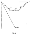
- FIG. 3E illustrates a phase plane trajectory which covers the whole region of excursion thereby eliminating any linear mode of operation that may be sensitive to parameter variations.
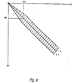
- FIG. 4 illustrates the preferred phase plane trajectory of the present invention.
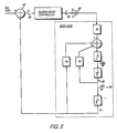
- FIG. 5 shows a typical servo actuator modeled as a second order system having a position error and position error velocity phase state.
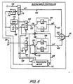
- FIG. 6 is a detailed diagram of the disc drive control system of the present invention wherein the sliding mode controller is responsive to a position error and a position error velocity phase state.
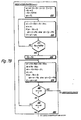
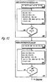
- FIG. 7A, 7B, and 7C are flow charts that describe the operation of the sliding mode controller of FIG. 6.
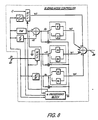
- FIG. 8 is a detailed block diagram of an alternative embodiment of the present invention where the sliding mode controller is responsive to an actuator position error, velocity error, and acceleration phase states.
- FIG. 9 illustrates a converging boundary layer around the sliding mode phase state trajectory.
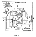
- FIG. 10 shows an integrator for integrating sgn( ⁇ ) in order to smooth the motor control signal.
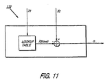
- FIG. 11 shows a preferred lookup table embodiment of the ⁇ processing block in the sliding mode controller.
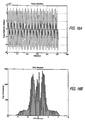
- FIG. 12A and 12B illustrate a simulated frequency and phase response of a typical focus servo loop in an optical disc drive.
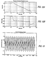
- FIG. 13 shows a nominal focus reference which was injected into the simulated focus servo loop of FIG. 12 for demonstrating performance of sliding mode control embodying the present invention as compared to conventional linear control.
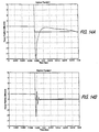
- FIG. 14A shows, for the nominal reference of FIG. 13, the response of a conventional linear controller to the focus capture transient.
- FIG. 14B shows, for the nominal reference of FIG. 13, the response of the sliding mode controller embodying the present invention to the focus capture transient.
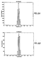
- FIG. 15A is a resulting histogram of the focus error signal during focus tracking when simulating the focus servo loop using the nominal reference signal of FIG. 13 and a conventional linear controller.
- FIG. 15B is a resulting histogram of the focus error signal during focus tracking when simulating the focus servo loop using the nominal reference signal of FIG. 13 and the sliding mode controller embodying the present invention.
- FIG. 16A is a worst case focus reference signal injected into the simulated focus servo loop of FIG. 12.
- FIG. 16B is a resulting histogram of the focus error signal during focus tracking when simulating the focus servo loop using the worst case reference signal of FIG. 16A and the sliding mode controller embodying the present invention.
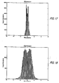
- FIG. 17 shows, for sliding mode control, a histogram of the focus error during focus tracking when the force constant is increased by 25%.
- FIG. 18 shows, for sliding mode control, a histogram of the focus error during focus tracking when the force constant is decreased by 50%.
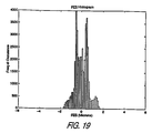
- FIG. 19 shows, for sliding mode control, a histogram of the focus error during focus tracking when the resonant peak at 10 kHz is increased by 10 dB.
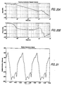
- FIG.s 20A and 20B show the frequency and phase response of a typical centerline servo tracking system in an optical disc drive used to simulate operation of embodiments of the present invention.
- FIG. 21 shows a nominal radial reference which was injected into the simulated centerline servo tracking system of FIG. 20 for demonstrating the performance of sliding mode control embodying the present invention as compared to conventional linear control.
- FIG. 22A is a resulting histogram of the tracking error signal during centerline tracking when simulating the tracking servo loop using the nominal reference signal of FIG. 21 and a conventional linear controller.
- FIG. 22B is a resulting histogram of the tracking error signal during centerline tracking when simulating the tracking servo loop using the nominal reference signal of FIG. 21 and the sliding mode controller embodying the present invention.
- FIG. 2A is an overview of the optical disc drive servo control system embodying the present invention which implements the coarse seeking operation.
- a spin motor 13 spins an optical disc 14 with computer data recorded thereon over an optical read head assembly 8 .
- the read head assembly 8 as described above with reference to FIG. 1A, comprises an objective lens (OL) 5 for focusing a laser beam onto the disc.
- OL objective lens
- a DC motor (DCM) 15 rotates the lead screw 9 in order to effectuate the coarse seek operation.
- a track counter 16 connected to receive an RF read signal 17 from the read head 8 , detects track crossings and generates an estimated read head track position 18A .
- Other well known methods for detecting the read head track position such as shaft encoders or Hall sensors, may be used in place of the track counter 16 .
- a state estimator 19 processes the estimated track position 18A and the DCM motor control signal 24 to generate a more accurate estimated position (Est. POS) 18B .
- the Est. POS 18B is subtracted from a reference position (Ref. POS) 20 and the OL carriage unit VCM control signal 26 (after low pass filtering 25 ) at adder 21 to generate a position error signal X1 22 .
- the reference position (Ref. POS) 20 indicates the selected track from which data is to be read.
- a sliding mode controller 23 responsive to the position error X1 22 , computes a motor control signal U 24 applied to the DCM 15 , thereby sliding the read head 8 to the selected track.
- Track counters 16 for use in optical disc storage systems are well known by those skilled in the art, an example of such is disclosed in U.S. Patent No. 5,406,535 the disclosure of which is hereby incorporated by reference.
- the state estimator 19 filters out errors in the track position information caused by noise in the recording channel and errors generated by the track position transducer (track counter 16 ). In the embodiment of the sliding mode controller shown in FIG. 6, the state estimator 19 can also replace the differentiator 102 in order to generate the position error velocity phase state X2.
- State estimators are well known by those skilled in the art, with one example described in U.S. Patent No. 4,679,103, the disclosure of which is hereby incorporated by reference. In addition to state estimators, other well known techniques may be used for generating the actuator phase states without departing from the scope of the present invention.
- the read head assembly 8 comprises an objective lens (OL) 5 for focusing a laser beam onto the disc 14 , a quadrant photodetector 6 for generating an RF read signal 17 and astigmatic focus error signals 27 , and two photo diodes ( 7A,7B ) for generating tracking error signals ( 28A,28B ).
- a FES generator 29 responsive to the focus error signals 27 from the quadrant photodetector 6 , generates a focus error signal 30 applied to a sliding mode controller 31 which generates a motor control signal 32 applied to the OL VCMs ( 10A,10B ).
- the RF read signal is computed as (A+B+C+D) and the focus error signal (FES) 30 is computed as (A+C)-(B+D).
- a TES generator 33 responsive to the tracking error signals ( 28A,28B ), generates a centerline tracking error signal (TES) 34 which, as described above, is computed as (F-E).
- the sliding mode controller 31 is de-activated (i.e., the focus servo loop is opened) and the OL VCMs ( 10A,10B ) move the OL carriage unit 11 away from the disc 14 until it is out of focus. Then, with the loop still open, the OL VCMs ( 10A,10B ) slowly move the OL 5 toward the disc until the FES 30 indicates that the OL 5 is within its pull-in range as defined by the linear region of FIG. 1D. The focus servo loop is then closed, and the sliding mode controller 31 begins tracking the in-focus position.
- the OL carriage unit 11 can perform the entire seek without having to move the entire sled assembly 8 .
- the track counter 16 and state estimator 19 operate the same as in a coarse seek operation, and the position error X1 35 is generated by subtracting the Est. POS 18B and the TES 34 from the reference position (Ref. POS) 20 at adder 36 .
- a sliding mode controller 37 responsive to the position error X1 35 , generates a motor control signal 26 applied to the OL VCMs ( 10A,10B ) in order to rotate the OL carriage unit 11 in the direction of the selected track.
- the OL VCM control signal 26 is applied to the sled servo control system of FIG. 2A at adder 21 , thereby moving the sled assembly 8 toward the selected track until the OL carriage unit 11 is again in its center position.
- FIG. 3A Operation of a sliding mode controller is understood with reference to FIG. 3A. Shown is an example second order system 44 controlled by an example sliding mode controller 45 that switches 46 between a positive gain 47 and negative gain 48 not necessarily equal in magnitude.
- a position error X1 49 is generated at the output of adder 50 by subtracting an estimated position 51 of the controlled system from a desired position reference position 52 .
- the position error X1 49 is multiplied by the positive gain 47 or the negative gain 48 depending on the state of switch 46 to generate an acceleration command 53 as the input to the controlled system 44 .
- the output of integrator 54 is the velocity of the controlled system 44 which is also the negative of the position error velocity -X2 55 .
- switch 46 selects the positive gain 47 , it is a negative feedback system, and when switch 46 selects the negative gain 48 , it is a positive feedback system.
- the system In their individual structures the system is unstable. However, the system can be made stable by repeatedly switching between the two structures.
- Equation (1) Asin(Kt + ⁇ )
- X2 ⁇ K ⁇ Acos(Kt + ⁇ )
- X1 2 A 2 + X2 2 KA 2 1
- the phase plane plot of equation (4) is a set of ellipses with eccentricities A and ⁇ K ⁇ A as illustrated in FIG. 3B.
- the state space equation in positive feedback is:
- the phase plane plot of equation (7) is a set of hyperbolas with two asymptotes as shown in FIG. 3B.
- the switching operation is understood with reference to FIG. 3C where the predetermined third phase trajectory is shown as a linear segment 60 .
- the initial head position error is at point A, and the control system is initially switched to select the positive gain (i.e., negative feedback).
- the phase states follow the arc trajectory 64 of the negative feedback mode.
- the sliding mode controller switches to the negative gain and the phase states begin to follow the hyperbola trajectory 66 of the positive feedback mode.
- the controller switches back to the positive gain to drive the phase states along arc 68 back toward the third phase trajectory 60 .
- phase states slide along the linear segment 60 toward the origin of the phase plane.
- the system switches to a tracking mode where the sliding mode controller repeatedly switches between positive and negative feedback in order to keep the phase states near the origin of the phase plane, thereby keeping the read head 8 aligned over the centerline of the selected track.
- Equation (8) is the average response of the system along the sliding line and it is substantially unaffected by variations in the parameter K or by external load disturbances. Consequently, it is not necessary to know the exact parameters of the system in order to determine the value for K. Equation (8), together with the existence Equation (11) below, prove that the system is globally stable within the sliding mode region.
- the sliding mode controller determines when to switch between the positive and negative gains by observing the phase state values.
- the sliding mode controller switches to the positive gain when ⁇ •X1>0 and to the negative gain when ⁇ •X1 ⁇ 0 in order to drive the phase states toward the linear trajectory.
- Equation (11) is known as the existence equation and it is used to determine values for the positive and negative gains.
- the linear sliding mode trajectory 60 of FIG. 3C has the disadvantage in that it initially operates in a linear feedback mode, and the initial arc trajectory 64 may drift due to parameter variation and external load disturbance. This problem is reduced by extending the sliding mode region of operation.
- a phase trajectory adjustor can continuously adjust the slope of the linear segment as shown in FIG. 3D. After the phase states reach the first sliding line 65 and follow it for a predetermined amount of time, the phase trajectory adjustor increases the slope to sliding line 67 by increasing the constant C.
- the system operates in a linear mode (non-sliding mode) only during the inter-segment transitions. Eventually, the slope is increased to a predetermine maximum at sliding line 69 at which point the phase states slide along line 69 toward the origin of the phase plane.
- phase trajectory to cover the entire region of excursion. This is illustrated in FIG. 3E where the phase trajectory is comprised of three linear segments ⁇ 1 72 , ⁇ 2 74 , and ⁇ 3 76 :
- C2 is constrained to 0 ⁇ C2 ⁇ K ⁇ , but all three segments are also constrained by the maximum acceleration, constant velocity, and deceleration limits of the actuator.
- This trajectory comprises a substantially parabolic acceleration segment ⁇ 1 80 , a linear constant velocity segment ⁇ 2 82 , a second substantially parabolic deceleration segment ⁇ 3 84 , and a linear deceleration segment ⁇ 4 86 :
- ⁇ 1 C1•X2 2 + X1 - X1I;
- ⁇ 3 -C2•X2 2 + X1;
- ⁇ 4 X2 + C3•X1;
- FIG. 5 shows the optical disc servo control systems modeled as second order plants.
- the output of the sliding mode controller U 60 is amplified 62 and input into the DCM 15 or VCMs (10A,10B) for actuating the lead screw 9 or OL carriage unit 11 , respectively.
- the parameters of the DCM/VCM are:
- the position error phase state X1 66 is observed at the output of adder 68 , and the position error velocity phase state X2 is observed as the negative of the DCM/VCM velocity 92 .
- the disc drive control system of the present invention operates optimum with the position error velocity X2 as the only control signal during a seek since the position error X1 is initially much larger than the position error velocity X2. Removing the position error X1 from the feedback loop during seeks reduces the amount of switching noise. When the phase states reach a predetermined point on the phase trajectory, the system switches the position error X1 phase state back into the control loop.
- FIG. 6 shows one embodiment for the sliding mode controllers of the present invention.
- the position error X1 22 is input into the sliding mode controller, and a differentiator 102 differentiates the position error X1 22 to generate the position error velocity signal X2 100 .
- the state estimator 19 generates the position error velocity X2 100 .
- Two switching gain circuits 104 and 106 multiply the position error ⁇ X1 130 and error velocity ⁇ X2 132 control signals, respectively.
- Multipliers 108 and 110 responsive to the phase states ⁇ X1 and X2 and the current trajectory segment ⁇ i, control the switching operation of the gain circuits.
- a ⁇ processing block 112 responsive to the phase states X1 and X2, implements the trajectory segment switching logic to determine which segment ⁇ i of the phase trajectory the phase states are to follow.
- the operation of the ⁇ processing block 112 , the integrator 116 , the reference error velocity generator 114 , and multiplexors 118 , 120 , and 122 are discussed in detail bellow.
- the gain values ⁇ i, ⁇ i, ⁇ i and ⁇ i in switching gain blocks 104 and 106 are programmably set to appropriate values according to the current trajectory segment being followed by the phase states. Also, the gain values are programmed to predetermined values depending on whether the controller is executing a forward or reverse seek. Using the existence equation (11) and the phase trajectory equations (13), (14), (15) and (16), appropriate constraints for the gain values for each segment of the phase trajectory shown in FIG. 4 can now be computed to ensure sliding mode.
- FIG. 6 Operation of the sliding mode controller shown in FIG. 6 will now be further explained in the context of a coarse seek operation with reference to FIG. 2A and centerline tracking with reference to FIG. 2B. It is noted, however, that the following description applies also to the focus servo loop; that is, flow charts of FIG. 7A, 7B, and 7C describe the operation of sliding mode controllers 23 , 31 and 37 of FIG. 2A and FIG. 2B.
- the read head 8 tracks 204 the currently selected track until a seek forward or seek reverse command is received.
- SEEK? 206 is YES and the head reference position, Ref. POS 20 , is updated to a newly selected track.
- the initial head position error X1 22 at the output of adder 21 of FIG. 2A is the difference between the current track 18B output from state estimator 19 and the newly selected track (i.e., Ref. POS 20 ).
- the sliding mode controller 23 initializes various parameters 210 .
- the position error phase state X1 22 is switched out of the sliding mode control.
- the ⁇ processing block 112 selects, over line 126 , the ground plane as the output of multiplexor 122 .
- ⁇ X1 130 is set to zero in order to disable the switching action of multiplier 110 and to remove the contribution of ⁇ 1 from the computation of the motor command U 24 at the output of adder 103 .
- the velocity phase state ⁇ X2 132 is initialized to a predetermined value to ensure the actuator begins moving in the desired direction (i.e., moving in reverse toward the selected track).
- the ⁇ processing block 112 selects, over line 124 , X2Ref 114 as the output of multiplexor 120 .
- the ⁇ processing block 112 also selects, over line 126 , the predetermined constant C 134 as the output of multiplexor 118 (the third input ⁇ 3 109 to adder 103 ).
- the function of the predetermined constant C 134 and the integrator 116 are discussed in further detail bellow.
- the sliding mode controller 23 continuously computes and outputs the motor command signal U 24 at the output of adder 103 .
- ⁇ 1 is updated according to equation (13) and ⁇ i 128 is assigned to ⁇ 1.
- Multiplier 108 (which can be implemented as a simple XOR of the operand sign bits) multiplies ⁇ i by X2 and switches gain block 104 to ⁇ i if the result is positive and to ⁇ i if the result is negative.
- Gain block 104 multiplies ⁇ X2 132 (X2Ref 114 ) by the selected gain to generate ⁇ 2.
- Adder 103 adds ⁇ 1, ⁇ 2, and ⁇ 3 to generate the motor command U 24 . Since ⁇ 1 is zero during acceleration and ⁇ 3 is insignificantly small, the motor command signal U 24 is predominately equal to ⁇ 2.
- the track counter 16 updates the current track position.
- the state estimator 19 processes the track count 18A and the current motor command 24 to update the estimated position signal 18B .
- Adder 21 outputs the new position error X1 22 , and differentiator 102 computes the new velocity phase state X2 100 as X1(N) - X1(N-1).
- the sliding mode controller 23 generates the motor command signal U 24 in flow chart 218 as a function of the velocity phase state X2 100 .
- the ⁇ processing block 112 updates ⁇ 1, ⁇ 2, and ⁇ 3 according to equations (13), (14), and (15), respectively.
- the output ⁇ i 128 of ⁇ processing block 112 is assigned to ⁇ 1.
- multiplier 108 sets the state of switching gain block 104 in order to drive X1 and X2 toward the ⁇ 1 80 phase trajectory of FIG. 4.
- the next command U 24 is generated and the read head 8 continues to move toward the selected track.
- the ⁇ processing block 112 continuously checks the location of the phase states with respect to the acceleration trajectory ⁇ 1 80 to determine when to switch to the next trajectory segment.
- the next trajectory segment will either be the constant velocity segment ⁇ 2 82 or, if the seek distance is sufficiently short, the deceleration segment ⁇ 3 84 .
- the ⁇ processing block 112 determines when to switch to the next trajectory. If ⁇ 1 ⁇ ⁇ 3? 220 is YES, then the ⁇ processing block 112 switches to the deceleration trajectory ⁇ 3 84 . Else if ⁇ 1 ⁇ ⁇ 2? 222 is YES, then the ⁇ processing block 112 switches to the constant velocity trajectory ⁇ 2 82 . If both 220 and 222 are NO, then the sliding mode controller 23 loops around and computes the next motor command U 24 according to flow chart 218 ⁇
- the gain constants for switching gain blocks 104 and 106 are updated 228 to values corresponding to the constant velocity trajectory ⁇ 2 82 of FIG. 4.
- the ⁇ processing block 112 updates ⁇ 2 and ⁇ 3 according to equations (14) and (15), respectively.
- the output ⁇ i 128 of ⁇ processing block 112 is assigned to ⁇ 2.
- multiplier 108 sets the state of switching gain block 104 in order to drive X1 and X2 toward the ⁇ 2 82 phase trajectory.
- the next command U 24 is generated and the read head 8 continues to move toward the selected track.
- the ⁇ processing block 112 continuously checks the location of the phase states with respect to the constant velocity trajectory ⁇ 2 82 to determine when to switch to the deceleration trajectory segment ⁇ 3 84 . If ⁇ 2 ⁇ ⁇ 3? 232 is YES, then the ⁇ processing block 112 switches to the deceleration trajectory ⁇ 3 84 . Otherwise, the sliding mode controller 23 loops around and computes the next command U 24 according to flow chart 230 .
- the ⁇ processing block 112 updates ⁇ 3 and ⁇ 4 according to equations (15) and (16), respectively.
- the output ⁇ i 128 of ⁇ processing block 112 is assigned to ⁇ 3.
- multiplier 108 sets the state of switching gain block 104 in order to drive X1 and X2 toward the ⁇ 3 84 phase trajectory.
- the next command U 24 is generated to decelerate the read head 8 toward the selected track.
- the ⁇ processing block 112 continuously checks the location of the phase states with respect to the deceleration trajectory ⁇ 3 84 to determine when to switch to the tracking trajectory segment ⁇ 4 86 . If ⁇ 4 ⁇ ⁇ 3? 240 is YES, then the ⁇ processing block 112 switches to the tracking trajectory ⁇ 4 86 . Otherwise, the sliding mode controller 23 loops around and computes the next command U 24 according to flow chart 238 .
- the tracking trajectory ⁇ 4 86 of FIG. 4 is executed by sliding mode controller 23 of FIG. 2A to keep the read head assembly 8 positioned over the desired track, and it is also executed by sliding mode controller 37 of FIG. 2B to keep the OL carriage unit 11 aligned over the centerline of the selected track.
- the sliding mode controller 37 of FIG. 2B rotates the OL carriage unit 11 according to the phase state trajectories of FIG. 4 to effectuate the entire seek instead of sliding the read head assembly 8 along the lead screw 9 .
- the gain constants for switching gain blocks 104 and 106 are updated 202 to values corresponding to the tracking trajectory ⁇ 4 86 of FIG. 4.
- the ⁇ processing block 112 selects via line 126 the output of integrator 116 as the output of multiplexor 118 (i.e., ⁇ 3).
- the ⁇ processing block 112 also switches the position error phase state X1 22 back into the sliding mode computation, by selecting via line 126 , as the output of multiplexor 122 , the position error phase state X1 22 as the input to multiplier 110 . Again, the position error phase state X1 22 is not used during seeks in order to reduce switching noise.
- the ⁇ processing block 112 updates ⁇ 4 according to equations (16).
- the output ⁇ i 128 of ⁇ processing block 112 is assigned to ⁇ 4.
- multipliers 108 and 110 set the state of switching gain blocks 104 and 108 , respectively, in order to drive X1 and X2 toward the ⁇ 4 86 phase trajectory.
- the next command U 26 is generated and applied to the OL VCMs ( 10A,10B ) to continue tracking the centerline of the selected track.
- biasing forces can cause the OL carriage unit 11 to have a steady state DC offset from the centerline.
- Typical biasing forces include the radial component of the windage caused by the rotating discs, tilt of the disc stack, biases in the flexible cables, and electrical offsets.
- an integrator 116 integrates the position error phase state X1 22 and its output 109 is summed 103 into the output 26 of the sliding mode controller 37 .
- the biasing forces do not vary with time, however, they do vary with the radial position of the OL carriage unit 11 . Therefore, the steady state integration value 109 corresponding to the biasing forces for each track is stored in memory.
- the integrator 116 is disabled and the steady state integration value stored in memory corresponding to the selected new track is added 103 as a constant 134 to the control signal 26 .
- the integrator 116 is re-enabled and its output added 103 back into the control signal 26 .
- the sliding mode controller ( 23,37 ) operates as described in the flow charts of FIG.s 7A, 7B, and 7C except that the inequalities are reversed.
- the ⁇ processing block 112 can also adjust the slope of the linear phase trajectory segment as shown in FIG. 3D.
- An alternative embodiment of the ⁇ processing block 112 would be to compare the position error and velocity phase states to values stored in a look up table where the stored values represent the phase plane trajectory shown in FIG. 4.
- FIG. 8 An alternative embodiment for the sliding mode controller of the present invention is shown in FIG. 8.
- a reference velocity Vref is generated as a function of the position error X1 corresponding to the velocity profiles ⁇ 1 80 and ⁇ 3 84 shown in FIG. 4.
- the reference velocity generator can be implemented with a lookup table or with polynomial equations.
- An actuator velocity error phase state Xv is generated by subtracting an estimated actuator velocity -X2 from the reference velocity Vref.
- An actuator acceleration phase state X ⁇ is generated by taking the second derivative of the position error X1.
- Phase states Xv and X ⁇ are multiplied by respective switching gain blocks to generate control signals ⁇ 2 and ⁇ 4. As discussed with reference to FIG. 6 and 7, control signal ⁇ 1 is disabled during seeks and ⁇ 3 is insignificantly small.
- the motor control signal U is a function of ⁇ 2 and ⁇ 4 during seek accelerate and seek decelerate.
- the sliding mode controller of FIG. 8 operates as described in FIG. 6 and 7 during seek at constant velocity and tracking.
- trajectory segments ⁇ i used by the ⁇ processing block of FIG. 8 are defined as:
- the sliding mode controller embodying the present invention provides further improvements in chatter reduction by defining a boundary layer around the sliding trajectory ⁇ . This is illustrated in FIG. 9 which shows a linear segment for the sliding trajectory ⁇ having a boundary layer defined as an offset ⁇ added to ⁇ .
- the boundary layer reduces chatter by reducing the amount of switching in the system. Without the boundary layer, the switching gain blocks 104 and 106 of FIG. 6 will switch every time the phase states cross the sliding line (i.e., every time ⁇ changes sign). The boundary layer results in hysteresis which causes the gain blocks to switch only after the phase states cross over the boundary line.
- the boundary layer offset ⁇ added to the sliding line ⁇ is a predetermined constant until the phase states reach a predetermined value (X1 c ,X2 c ) at which time the offset ⁇ is computed as the sum of the phase states X1 and X2 so that the boundary layer converges to the origin of the phase plane, as shown in FIG. 9, in order to prevent oscillations around the origin.
- the sliding mode controller embodying the present invention achieves still better chatter reduction by generating the control signal U proportional to an integral of sgn( ⁇ ).
- the control signal is smoothed to attenuate the high frequency components that can generate electromagnetic and/or acoustic emissions.
- ⁇ i from ⁇ processing block 112 is input into an integrating block 101 which computes the following function: sat [ ⁇ K•sgn( ⁇ i)dt]; where: The output 128 of the integrating block 101 controls the state of switching gain blocks ( 104,106 ) and is also input into an absolute value function 111 .
- the control signal at the output of adder 103 is then attenuated by the absolute value of the integrated sgn( ⁇ i) through a multiplier 113 to generate the smoothed control signal U.
- the ⁇ processing block 112 of the present embodiment can be implemented using a lookup table rather than switching between trajectory segments.
- the phase states can be used as an index into a lookup table in order to implement the phase state trajectory ⁇ .
- the phase state trajectory is redefined according to the following derivation:
- the various gain values in switching gain blocks 104 and 106 of FIG. 6 are programmably set to appropriate values according to the trajectory segment being followed by the phase states and whether the controller is executing a forward or reverse seek.
- appropriate ranges for the gain values for each segment of the phase state trajectory shown in FIG. 4 were determined.
- the sliding mode controllers for focus, seeking and tracking are implemented using binary coefficients. That is, the various gain values in switching gain blocks 104 and 106 are selected from the set 2 n , where n is a positive or negative integer.
- Binary coefficients may be used for the switching gains because the gains need only be within a predetermined range as discussed above. Consequently, the memory requirements for storing the coefficients is reduced and complex hardware multipliers are obviated; that is, multiplying by binary coefficients can be accomplished using only shift registers.
- FIG. 14B illustrates the response of the sliding mode controller of the present invention to the capture transient which is much better than for a typical linear controller as shown in FIG. 14A.
- FIG. 15B shows a histogram of the focus error signal (FES) during focus tracking and, as compared to the conventional linear controller of FIG. 15A, sliding mode control operates within the required 5 micron deviation. Further, however, sliding mode control better compensates for parametric variations and external load disturbances. Even under a worst case focus reference condition as shown in FIG. 16A, an optical disc drive system employing the present invention remained in focus as shown in FIG. 16B without plant modifications; whereas a system employing conventional linear control could not maintain the required 5 micron deviation.
- FES focus error signal
- FIG. 17 shows the steady state focus histogram when the focus actuator force constant (Kt in FIG. 5) is increased by 25%.
- FIG. 18 shows the steady state focus histogram when the force constant is decreased by 50%.
- FIG. 19 shows the steady state focus histogram when the resonance peak 10 kHz is increased by 10 dB.
- the mechanical transfer function was characterized with the frequency and phase response shown in FIG. 20A and 20B.
- the tracking aspect of the present invention was simulated with a nominal tracking reference shown in FIG. 21.
- the resulting histogram for centerline tracking error (TES) using sliding mode control is shown in FIG. 22B.
- TES centerline tracking error
- sliding mode control maintains the tracking error within a 0.2 micron deviation while better compensating for parametric variations and external load disturbances.
- the sliding mode controller may be implemented in hardware or software and in continuous or discrete time, and higher order phase states could be used in place of, or in addition to, the particular phase states disclosed.
Abstract
An optical disc storage system comprises a sliding mode controller for actuating an optical read head assembly over an optical disc during focus capture, focus tracking, track seeking and centerline tracking. The sliding mode controller is a non-linear control system which operates by switching between positive and negative feedback in order to force certain phase states (such as the read head's position error and velocity) to follow a predetermined phase state trajectory. Sliding mode control provides improved compensation to parametric variations, external load disturbances and other transients such as, for example, the focus capture transient. Furthermore, the sliding mode positive and negative feedback gains need only be within a predetermined range, thereby allowing gain values of 2n which significantly reduces the complexity and cost of the gain multipliers.
Description
- The present invention relates to optical storage systems, particularly to controlling the read head actuator in an optical disc drive.
- Optical disc drives, such as CD-ROMs, are commonly used for storing large amounts of digital data on a single disc for use in audio/video or computer applications, and the like. The data on an optical disc is typically recorded as a series of "pits" arranged in tracks, where the length of the pit determines the presence of a digital "0" bit or a "1" bit. To read this recorded data, a servo system focuses a laser beam onto the surface of the disc such that the characteristics of the reflected beam allow detection of the data pits.
- To this end, the servo system performs four operations: (1) a capture operation to "pull-in" the initial focus position, (2) a seek operation to move the beam to a desired track, (3) a centerline tracking operation to maintain the beam over the centerline of the selected track while reading the recorded data, and (4) a focus tracking operation to maintain proper focus as the disc spins over the beam.
- Conventional optical disc drives use a head assembly comprised of a laser diode for generating the laser beam which is focused onto the surface of the optical disc through an objective lens. FIG. 1A illustrates a typical three beam optical head assembly, the operation of which is well known by those skilled in the art. A
laser diode 1 produces a light beam which passes through a diffraction grating (not shown) splitting the main beam into three separate beams 2 (a center beam and two side beams); the threebeams 2 then pass through apolarization beam splitter 3 and a collimator lens (not shown). Thelight beams 2 are then reflected by aprism 4, through an object lens (OL) 5, and onto the surface of the optical disc (not shown). Thebeams 2 reflect off the optical disc, again pass through theOL 5, and then reflect off theprism 4 back toward thepolarization prism 3. Thepolarization prism 3 deflects the center beam onto aquadrant photodetector 6, and deflects the two side beams onto two tracking photodiodes (7A,7B). Thequadrant photodetector 6 generates a focus error signal (FES) for focusing theOL 5, and it generates an RF read signal for reading the recorded data. The tracking photodiodes (7A,7B) generate a tracking error signal (TES) used to maintain the position of theOL 5 over the centerline of a selected track while reading data from the disc. - In order to position the read head over a selected track during a seek operation, the
entire sled assembly 8 slides radially along alead screw 9 underneath the optical disc until the read head is positioned near the desired track. This coarse positioning (or coarse seeking) is accomplished by rotating thelead screw 9 in a clockwise or counterclockwise direction. Once near the selected track, OL voice coil motors (VCMs) (10A,10B) rotate anOL carriage unit 11 about a plastic hinge 12 in a "fine seeking" operation until theOL 5 is positioned directly over the desired track. Then, as the disc rotates and the track passes under the read head, the OL VCMs (10A,10B) perform fine adjustments in a "tracking" operation in order to maintain the position of theOL 5 over the centerline of the selected track as information is read from the disc. - The OL VCMs (10A,10B) can rotate the
OL carriage unit 11, and thereby theOL 5, about the plastic hinge 12 in a range that spans approximately 200 tracks on either side of its center position. Thus, if during a seek operation the selected track is within 200 tracks of the current track, theOL carriage unit 11 can perform the entire seek operation without needing to slide thesled assembly 8 along thelead screw 9. At the end of a short seek operation and while tracking the centerline of the selected track, thelead screw 9 slowly slides thesled assembly 8 toward the selected track until theOL carriage unit 11 is again in its center position. - The OL VCMs (10A,10B) also move the
OL carriage unit 11 up and down in the direction shown in order to "capture" and "track" theOL 5 focus position. For focus capture and focus tracking thequadrant photodetector 6 generates an astigmatic focus error signal indicative of the distance between theOL 5 and the optical disc. At the beginning of a capture operation, theOL carriage unit 1 is initially positioned sufficiently away from the disc so that it is out-of-focus. Then the OL VCMs (10A,10B) slowly move theOL carriage unit 11 toward the disc with the focus servo loop open until thequadrant photodetector 6 indicates that theOL 5 is within its focus pull-in range. Once within the pull-in range, the focus servo loop is closed and the initial focus point is captured. Thereafter, the OL VCMs (10A,10B) track the in-focus position in response to the astigmatic focus error signal (FES) as the read head seeks to selected tracks and reads data from the disc. - FIG. 1B illustrates how the changing image on the
quadrant photodetector 6 generates the focus error signal (FES). When the disc surface lies precisely at the focal point of theOL 5, a circular spot strikes the center of thequadrant photodetector 6. When the distance between the disc and theOL 5 decreases, the reflected image becomes elliptical. Similarly, when the distance between the disc and theOL 5 increases, an elliptical pattern again results, only rotated 90 degrees from the first elliptical pattern. Thus, as shown in FIG. 1C, thequadrant photodetector 6 generates the focus error signal (FES) according to (A+C)-(B+D), and it generates the RF read signal according to (A+B+C+D). FIG. 1D is a plot of the focus error signal (FES) versus the distance between theOL 5 and the optical disc, where the linear region defines the focus "pull-in" range for the focus capture operation. - Similar to the
quadrant photodetector 6, the tracking photodiodes (7A,7B) generate a tracking error signal (TES) used by the servo control system to maintain theOL 5 over the centerline of the selected track as the disc spins over the beam. FIG. 1E shows how the tracking photodiodes (7A,7B) generate the tracking error signal (TES) according to the intensity of the side beams. When positioned perfectly over the track's centerline, the tracking error signal is zero. When positioned to the left or right of the centerline, the tracking error signal (TES) is positive or negative, respectively. Thus, the tracking error signal (TES) is generated as (E-F) as illustrated by FIG. 1F. FIG. 1G is a plot of the tracking error signal (TES) versus the mistracking, where the linear region indicates the pull-in region for the tracking operation. - There are many difficulties inherent in controlling the read head actuator of an optical disc drive relative to focus capture, focus tracking, track seeking and centerline tracking. One significant aspect is the wide range of parametric variations that can occur due to internal factors, such as temperature and volt drift, as well as parametric variations in the servo system between disc drives. The servo system must be able to compensate for these parametric variations in order to perform adequately at the ever increasing data rates and densities.
- Yet another problem is that the above described capture operation does not always end successfully; rather it can fail due to over shooting the pull-in range as defined by the linear region of the focus error signal (FES) shown in FIG. 1D. That is, there is a significant capture transient associated with closing the focus servo loop (see FIG. 14A) that varies with such factors as the relative disk/head velocity variation, surface contaminations and the driving force of the focus VCMs. For this reason, optical storage devices are generally designed to repeat the capture operation several times.
- Still another problem is maintaining focus during seek operations which presents a significant external disturbance to the focus servo loop. If the focus is lost during a seek, the storage system must pause to perform a focus capture operation which can significantly increase the seek time.
- Yet another problem associated with optical disc servo systems is the optical coupling or feedthrough phenomena that occurs between the focus tracking and centerline tracking loops. U.S. patent no. 5,367,513 discloses one solution to the optical feedthrough problem, but it has disadvantages which are overcome by the present invention mainly, cost of implementation.
- Conventional servo systems found in optical storage systems typically implement a linear controller using Proportional-Integral-Derivative (PID) feedback and/or state estimators. The problem with conventional linear controllers, however, is they are sensitive to parametric variations in the servo system and to external load disturbances. Conventional adaptive linear controllers overcome this sensitivity problem by executing complex calibration routines or by continuously re-programming the controller to compensate for the parameter variations and load disturbances. However, adaptive linear controllers are complex and may require notch filters for filtering out mechanical resonances. Furthermore, conventional linear controllers are not adept to the above described problems inherent in controlling an actuator for an optical disc drive.
- There is, therefore, a need for an optical disc drive servo control system that is less sensitive to parametric variations, provides better control of transients, and avoids the implementation cost of a complex, adaptive linear controller.
- An optical disc storage system comprises a sliding mode controller for actuating an optical read head assembly over an optical disc during focus capture, focus tracking, track seeking and centerline tracking. The sliding mode controller is a nonlinear control system which operates by switching between positive and negative feedback in order to force certain phase states (such as the read head's position error and velocity) to follow a predetermined phase state trajectory. The positive and negative feedback gains need only be within a predetermined range, thereby allowing gain values of 2n which significantly reduces the complexity and cost of the gain multipliers.
- The resulting servo control system overcomes many of the inherent difficulties in actuating an optical read head, and at a much lower cost than conventional adaptive linear controllers. Specifically, it provides robust compensation for parametric variations that can occur due to such factors as temperature and voltage drift and parametric variations that occur between individual disc drives. Furthermore, sliding mode control better compensates for transients caused by external load disturbances as well as the transient associated with closing the servo loop during focus capture. Still further, sliding mode control provides a less complex solution to the above mentioned optical coupling between the focus tracking and centerline tracking servo loops.
- The invention provides an optical disc drive storage system for recording digital data, comprising:
- (a) at least one rotating optical disc comprising a plurality of data tracks recorded thereon;
- (b) an optical read head positioned over the optical disc for reading the digital data from the optical disc;
- (c) an actuator connected to the read head for positioning the read head over the optical disc;
- (d) a motor connected to the actuator comprising an input for receiving a motor control signal, the motor for controlling the motion of the actuator;
- (e) a phase state generator for generating at least one phase state signal; and
- (f) a sliding mode controller, responsive to the at least one phase state signal, for generating the motor control signal.
- The phase state generator may comprise a state estimator.
- The sliding mode controller may operate in a seek mode to move the read head from a current track to a selected track; in a tracking mode to maintain the read head over a centerline of a selected track; and in a focus mode to maintain the read head in a focus position over the disc.
- Preferably, the optical disc drive storage system comprises at least two phase states; the sliding mode controller switches between a first and a second structure; the first structure causes the two phase states to change relative to a phase plane to follow a first phase trajectory; the second structure causes the two phase states to change relative to the phase plane to follow a second phase trajectory; the first and second phase trajectories intercept in opposite directions in at least part of the phase plane; and by switching between the first and second structures the sliding mode controller causes the two phase states to change relative to the phase plane to substantially follow a predetermined third phase trajectory.
- Then the optical disc drive storage system may further comprise switching logic, responsive to the at least one phase state signal, for controlling the switching between the first and second structures.
- The invention also provides a method for controlling the motion of an optical read head positioned over a rotating optical disc storage medium, the optical disc comprises a plurality of data tracks recorded thereon, a motor actuates the read head over the optical disk, the method comprising the steps of:
- (a) generating at least one phase state signal representing a phase state of the motor;
- (b) comparing the phase state signal to a phase state value relative to a predetermined phase trajectory;
- (c) generating a motor control signal by multiplying the phase state signal by a first gain value in response to a first result of the comparison in step (b) and by multiplying the phase state signal by a second gain value in response to a second result of the comparison in step (b); and
- (d) applying the motor control signal to the motor to actuate the read head over the disc.
- In another aspect, the invention provides an optical disc drive storage system for recording digital data, comprising:
- (a) at least one rotating optical disc comprising a plurality of data tracks recorded thereon;
- (b) an optical read head positioned over the optical disc for reading the digital data from the optical disc;
- (c) an actuator connected to the read head for positioning the read head over the optical disk;
- (d) a motor connected to the actuator comprising an input for receiving a motor control signal, the motor for controlling the motion of the actuator;
- (e) a phase state generator for generating at least one phase state signal; and
- (f) a sliding mode controller, responsive to the at least one phase state signal, for generating the motor control signal, comprising:
- (a) a first input connected to receive an actuator position error signal X1 indicative of a difference between an estimated actuator position and a desired actuator position;
- (b) a first switching gain block for selectively multiplying a first phase state signal, proportional to the actuator position error signal X1, by a first gain or by a second gain according to a first predetermined relationship between the first phase state signal and a first phase state trajectory to generate a first proportional phase state signal;
- (c) an integrator, responsive to the actuator position error signal X1, for generating an integrated phase state signal; and
- (d) an adder for adding the first proportional phase state signal with the integrated phase state signal to generate a motor control signal applied to the motor.
- Preferably, the first phase state trajectory comprises a first and second trajectory segment; and the first and second gains are programmably adjusted to different values corresponding to the first and second trajectory segments.
- Preferably also, the sliding mode controller operates in a forward and reverse seek modes to move the read head from a current track to a selected track; and the first and second gains are programmably adjusted to different values corresponding to the forward seek mode and the reverse seek mode.
- In a further aspect, the invention provides, an optical disc drive storage system for recording digital data, comprising:
- (a) at least one rotating optical disc comprising a plurality of data tracks recorded thereon;
- (b) an optical read head positioned over the optical disc for reading the digital data from the optical disc;
- (c) an actuator connected to the read head for positioning the read head over the optical disk;
- (d) a motor connected to the actuator comprising an input for receiving a motor control signal, the motor for controlling the motion of the actuator;
- (e) a phase state generator for generating at least one phase state signal; and
- (f) a sliding mode controller, responsive to the at least one phase state signal, for generating the motor control signal, comprising:
- (a) a first switching gain block having a first and second gain value connected to receive a first actuator phase state signal;
- (b) a second switching gain block having a third and fourth gain value connected to receive an actuator position error signal X1; and
- (c) a means for attenuating the effect of the second switching gain block during at least part of the seek mode.
- In a still further aspect, the invention provides an optical disc drive storage system for recording digital data, comprising:
- (a) at least one rotating optical disc comprising a plurality of data tracks recorded thereon;
- (b) an optical read head positioned over the optical disc for reading the digital data from the optical disc;
- (c) an actuator connected to the read head for positioning the read head over the optical disk;
- (d) a motor connected to the actuator comprising an input for receiving a motor control signal, the motor for controlling the motion of the actuator;
- (e) a phase state generator for generating at least one phase state signal; and
- (f) a sliding mode controller, responsive to the at least one phase state signal, for generating the motor control signal, comprising:
- (a) a first input connected to receive an actuator position error signal X1, indicative of a difference between an estimated actuator position and a desired actuator position;
- (b) a first switching gain block for selectively multiplying a first phase state signal, responsive to the actuator position error signal X1, by a first gain or by a second gain according to a first predetermined relationship σ between the first phase state signal and a first phase state trajectory, to generate a first proportional phase state signal; and
- (c) a multiplier for multiplying a computed control signal, responsive to the first proportional phase state signal, by a phase state trajectory signal, responsive to the first predetermined relationship σ, to generate a motor control signal applied to the motor.
- Preferably, the first phase state trajectory comprises a first and second trajectory segment; and the first and second gains are programmably adjusted to different values corresponding to the first and second trajectory segments.
- Preferably also, the sliding mode controller operates in a forward and reverse seek modes to move the read head from a current track to a selected track, and in a tracking mode to keep the read head substantially aligned over a centerline of the selected track; and the first and second gains are programmably adjusted to different values corresponding to the forward seek mode and the reverse is seek mode.
- Conveniently, the first phase state trajectory has a predetermined boundary layer; and the first predetermined relationship σ is computed relative to the boundary layer.
- Then, the boundary layer may converge to an origin of a phase plane as the first phase state signal converges to the origin of the phase plane. The boundary layer may be a predetermined constant added to the phase state trajectory. The boundary layer may be computed using the phase state signal.
- In a yet further aspect, the invention provides a sliding mode controller for positioning a read head over a rotating disc storage medium, comprising:
- (a) an input connected to receive a phase state;
- (b) a switching multiplier for multiplying the phase state by a first gain value and by a second gain value according to a predetermined relationship between the phase state and a phase state trajectory, the first and second gain values selected from the
set 2n where n is an integer; and - (c) an output for outputting an actuator control signal from the switching multiplier to control the position of the read head.
- Examples of the present invention will now be described in conjunction with the drawings, wherein:
- FIG. 1A is a block diagram of a conventional three beam optical read head assembly including the servo optical sensing circuits used for focus capture, focus tracking and centerline tracking.
- FIG. 1B shows the various patterns which may be generated on a quadrant photodetector based on the focus condition of the laser beam.
- FIG. 1C illustrates how to generate a focus error signal (FES) and an RF read signal from the quadrant photodetector.
- FIG. 1D is a plot of the focus error signal (FES) versus the position of the objective lens relative to the disc's surface.
- FIG. 1E shows various tracking conditions which can exist for the three beam system.
- FIG. 1F illustrates how a three beam system generates the centerline tracking error signal (TES).
- FIG. 1H is a plot of the tracking error signal(TES) versus the mistracking position of the objective lens relative to the centerline of a selected track.
- FIG. 2A and 2B are exemplary block diagrams of the disc drive control systems embodying the present invention.
- FIG. 3A is a block diagram of a second order system controlled by an example sliding mode controller.
- FIG. 3B are the phase plane plots for the position error and error velocity phase states for the positive and negative feedback modes of the control system shown in FIG. 3A.
- FIG. 3C illustrates the operation of the sliding mode controller in driving the phase states toward a predetermine linear phase trajectory during a forward seek to a new track.
- FIG. 3D illustrates the effect of changing the slope of the linear phase trajectory in FIG. 3C in order to extend the sliding mode.
- FIG. 3E illustrates a phase plane trajectory which covers the whole region of excursion thereby eliminating any linear mode of operation that may be sensitive to parameter variations.
- FIG. 4 illustrates the preferred phase plane trajectory of the present invention.
- FIG. 5 shows a typical servo actuator modeled as a second order system having a position error and position error velocity phase state.
- FIG. 6 is a detailed diagram of the disc drive control system of the present invention wherein the sliding mode controller is responsive to a position error and a position error velocity phase state.
- FIG. 7A, 7B, and 7C are flow charts that describe the operation of the sliding mode controller of FIG. 6.
- FIG. 8 is a detailed block diagram of an alternative embodiment of the present invention where the sliding mode controller is responsive to an actuator position error, velocity error, and acceleration phase states.
- FIG. 9 illustrates a converging boundary layer around the sliding mode phase state trajectory.
- FIG. 10 shows an integrator for integrating sgn(σ) in order to smooth the motor control signal.
- FIG. 11 shows a preferred lookup table embodiment of the σ processing block in the sliding mode controller.
- FIG. 12A and 12B illustrate a simulated frequency and phase response of a typical focus servo loop in an optical disc drive.
- FIG. 13 shows a nominal focus reference which was injected into the simulated focus servo loop of FIG. 12 for demonstrating performance of sliding mode control embodying the present invention as compared to conventional linear control.
- FIG. 14A shows, for the nominal reference of FIG. 13, the response of a conventional linear controller to the focus capture transient.
- FIG. 14B shows, for the nominal reference of FIG. 13, the response of the sliding mode controller embodying the present invention to the focus capture transient.
- FIG. 15A is a resulting histogram of the focus error signal during focus tracking when simulating the focus servo loop using the nominal reference signal of FIG. 13 and a conventional linear controller.
- FIG. 15B is a resulting histogram of the focus error signal during focus tracking when simulating the focus servo loop using the nominal reference signal of FIG. 13 and the sliding mode controller embodying the present invention.
- FIG. 16A is a worst case focus reference signal injected into the simulated focus servo loop of FIG. 12.
- FIG. 16B is a resulting histogram of the focus error signal during focus tracking when simulating the focus servo loop using the worst case reference signal of FIG. 16A and the sliding mode controller embodying the present invention.
- FIG. 17 shows, for sliding mode control, a histogram of the focus error during focus tracking when the force constant is increased by 25%.
- FIG. 18 shows, for sliding mode control, a histogram of the focus error during focus tracking when the force constant is decreased by 50%.
- FIG. 19 shows, for sliding mode control, a histogram of the focus error during focus tracking when the resonant peak at 10 kHz is increased by 10 dB.
- FIG.s 20A and 20B show the frequency and phase response of a typical centerline servo tracking system in an optical disc drive used to simulate operation of embodiments of the present invention.
- FIG. 21 shows a nominal radial reference which was injected into the simulated centerline servo tracking system of FIG. 20 for demonstrating the performance of sliding mode control embodying the present invention as compared to conventional linear control.
- FIG. 22A is a resulting histogram of the tracking error signal during centerline tracking when simulating the tracking servo loop using the nominal reference signal of FIG. 21 and a conventional linear controller.
- FIG. 22B is a resulting histogram of the tracking error signal during centerline tracking when simulating the tracking servo loop using the nominal reference signal of FIG. 21 and the sliding mode controller embodying the present invention.
- FIG. 2A is an overview of the optical disc drive servo control system embodying the present invention which implements the coarse seeking operation. A
spin motor 13 spins anoptical disc 14 with computer data recorded thereon over an opticalread head assembly 8. The readhead assembly 8, as described above with reference to FIG. 1A, comprises an objective lens (OL) 5 for focusing a laser beam onto the disc. During a coarse seek operation, the readhead assembly 8 slides radially under thedisc 14 along alead screw 9 until positioned under a selected track. A DC motor (DCM) 15 rotates thelead screw 9 in order to effectuate the coarse seek operation. Atrack counter 16, connected to receive an RF readsignal 17 from the readhead 8, detects track crossings and generates an estimated readhead track position 18A. Other well known methods for detecting the read head track position, such as shaft encoders or Hall sensors, may be used in place of thetrack counter 16. Astate estimator 19 processes the estimatedtrack position 18A and the DCMmotor control signal 24 to generate a more accurate estimated position (Est. POS) 18B. The Est.POS 18B is subtracted from a reference position (Ref. POS) 20 and the OL carriage unit VCM control signal 26 (after low pass filtering 25) atadder 21 to generate a positionerror signal X1 22. The reference position (Ref. POS) 20 indicates the selected track from which data is to be read. A slidingmode controller 23, responsive to theposition error X1 22, computes a motorcontrol signal U 24 applied to theDCM 15, thereby sliding theread head 8 to the selected track. - Track counters 16 for use in optical disc storage systems are well known by those skilled in the art, an example of such is disclosed in U.S. Patent No. 5,406,535 the disclosure of which is hereby incorporated by reference.
- The
state estimator 19 filters out errors in the track position information caused by noise in the recording channel and errors generated by the track position transducer (track counter 16). In the embodiment of the sliding mode controller shown in FIG. 6, thestate estimator 19 can also replace thedifferentiator 102 in order to generate the position error velocity phase state X2. State estimators are well known by those skilled in the art, with one example described in U.S. Patent No. 4,679,103, the disclosure of which is hereby incorporated by reference. In addition to state estimators, other well known techniques may be used for generating the actuator phase states without departing from the scope of the present invention. - Referring now to FIG. 2B, shown is a sliding mode control system of the present invention used for focus capture, focus tracking, fine seeking and centerline tracking. As discussed above with reference to FIG. 1A, the read
head assembly 8 comprises an objective lens (OL) 5 for focusing a laser beam onto thedisc 14, aquadrant photodetector 6 for generating an RF readsignal 17 and astigmatic focus error signals 27, and two photo diodes (7A,7B) for generating tracking error signals (28A,28B). - A
FES generator 29, responsive to the focus error signals 27 from thequadrant photodetector 6, generates afocus error signal 30 applied to a slidingmode controller 31 which generates amotor control signal 32 applied to the OL VCMs (10A,10B). As described above, the RF read signal is computed as (A+B+C+D) and the focus error signal (FES) 30 is computed as (A+C)-(B+D). ATES generator 33, responsive to the tracking error signals (28A,28B), generates a centerline tracking error signal (TES) 34 which, as described above, is computed as (F-E). - To capture the initial focus position, the sliding
mode controller 31 is de-activated (i.e., the focus servo loop is opened) and the OL VCMs (10A,10B) move theOL carriage unit 11 away from thedisc 14 until it is out of focus. Then, with the loop still open, the OL VCMs (10A,10B) slowly move theOL 5 toward the disc until theFES 30 indicates that theOL 5 is within its pull-in range as defined by the linear region of FIG. 1D. The focus servo loop is then closed, and the slidingmode controller 31 begins tracking the in-focus position. - For fine seeking operations, where the seek distance is less than 50 tracks, the
OL carriage unit 11 can perform the entire seek without having to move theentire sled assembly 8. Thetrack counter 16 andstate estimator 19 operate the same as in a coarse seek operation, and theposition error X1 35 is generated by subtracting the Est.POS 18B and theTES 34 from the reference position (Ref. POS) 20 atadder 36. A slidingmode controller 37, responsive to theposition error X1 35, generates amotor control signal 26 applied to the OL VCMs (10A,10B) in order to rotate theOL carriage unit 11 in the direction of the selected track. At the end of a fine seek operation, the OLVCM control signal 26 is applied to the sled servo control system of FIG. 2A atadder 21, thereby moving thesled assembly 8 toward the selected track until theOL carriage unit 11 is again in its center position. - Operation of a sliding mode controller is understood with reference to FIG. 3A. Shown is an example
second order system 44 controlled by an example slidingmode controller 45 that switches 46 between apositive gain 47 andnegative gain 48 not necessarily equal in magnitude. Aposition error X1 49 is generated at the output ofadder 50 by subtracting an estimated position 51 of the controlled system from a desiredposition reference position 52. Theposition error X1 49 is multiplied by thepositive gain 47 or thenegative gain 48 depending on the state ofswitch 46 to generate an acceleration command 53 as the input to the controlledsystem 44. The output ofintegrator 54 is the velocity of the controlledsystem 44 which is also the negative of the position error velocity -X2 55. Whenswitch 46 selects thepositive gain 47, it is a negative feedback system, and whenswitch 46 selects thenegative gain 48, it is a positive feedback system. In their individual structures the system is unstable. However, the system can be made stable by repeatedly switching between the two structures. - The state space equation in negative feedback is:


- The state space equation in positive feedback is:


- The two individual phase plane trajectories of equations (4) and (7) result in an unstable system since the phase states never reach the origin. It is possible, however, to reach the origin by driving the phase states along a third phase trajectory defined at the intersection of the negative and positive feedback trajectories. This is achieved by switching between the positive and negative gains in response to the current phase state values so that the phase states follow the predetermined third phase trajectory.
- The switching operation is understood with reference to FIG. 3C where the predetermined third phase trajectory is shown as a
linear segment 60. When a new track is selected, the initial head position error is at point A, and the control system is initially switched to select the positive gain (i.e., negative feedback). As the head begins to accelerate toward the selected track; the phase states follow thearc trajectory 64 of the negative feedback mode. When the phase states reach the beginning of thethird phase trajectory 60 at the intersection point B, the sliding mode controller switches to the negative gain and the phase states begin to follow thehyperbola trajectory 66 of the positive feedback mode. When the phase states cross thethird phase trajectory 60 at point C, the controller switches back to the positive gain to drive the phase states alongarc 68 back toward thethird phase trajectory 60. This switching action is repeated so that the phase states slide along thelinear segment 60 toward the origin of the phase plane. When the phase states are within a predetermined minimum distance from the origin of the phase plane, the system switches to a tracking mode where the sliding mode controller repeatedly switches between positive and negative feedback in order to keep the phase states near the origin of the phase plane, thereby keeping the readhead 8 aligned over the centerline of the selected track. - The time domain response of the control system when the phase states follow the sliding line of FIG. 3C is:

- The sliding mode controller determines when to switch between the positive and negative gains by observing the phase state values. The linear phase trajectory of FIG. 3C is defined by:

linear segment 60. By observing the phase states, the sliding mode controller switches the gains so that:
- The overall response of the system is made faster by increasing the slope of the sliding line (i.e., increasing C). However, an important limitation in sliding mode control is that the third phase trajectory must be constrained to a region in the phase plane where the positive and negative feedback phase trajectories intersect in opposite directions. From FIG. 3C it follows that the slope of the sliding line must be constrained to 0<C<√


- The linear sliding
mode trajectory 60 of FIG. 3C has the disadvantage in that it initially operates in a linear feedback mode, and theinitial arc trajectory 64 may drift due to parameter variation and external load disturbance. This problem is reduced by extending the sliding mode region of operation. For instance, a phase trajectory adjustor can continuously adjust the slope of the linear segment as shown in FIG. 3D. After the phase states reach the first slidingline 65 and follow it for a predetermined amount of time, the phase trajectory adjustor increases the slope to slidingline 67 by increasing the constant C. The system operates in a linear mode (non-sliding mode) only during the inter-segment transitions. Eventually, the slope is increased to a predetermine maximum at sliding line 69 at which point the phase states slide along line 69 toward the origin of the phase plane. - A more robust implementation is to define a phase trajectory to cover the entire region of excursion. This is illustrated in FIG. 3E where the phase trajectory is comprised of three linear segments σ1 72, σ2 74, and σ3 76:

- X1 = the actuator position error phase state;
- X2 = the actuator position error velocity phase state;
- C1 = the slope of the first segment;
- C2 = the slope of the third segment;
- XI = an initial actuator position error; and
- X2I = a predetermined constant position error velocity.
- As described above, C2 is constrained to 0<C2<√

- The optimum phase plane trajectory, and the preferred embodiment of the present invention, is illustrated in FIG. 4. This trajectory comprises a substantially parabolic
acceleration segment σ1 80, a linear constantvelocity segment σ2 82, a second substantially parabolic deceleration segment σ3 84, and a linear deceleration segment σ4 86:


- X1 = the actuator position error phase state;
- X2 = the actuator position error velocity phase state;
- C1 = a predetermined acceleration constant;
- X1I = an initial actuator position error;
- X2I = a predetermined constant position error velocity;
- C2 = a predetermined deceleration constant; and
- C3 = a predetermined slope of the linear deceleration segment.
- FIG. 5 shows the optical disc servo control systems modeled as second order plants. The output of the sliding
mode controller U 60 is amplified 62 and input into theDCM 15 or VCMs (10A,10B) for actuating thelead screw 9 orOL carriage unit 11, respectively. The parameters of the DCM/VCM are: - Kt = Torque Constant;
- Kv = Coefficient of Viscous Damping;
- Ks = Coefficient of Coulomb Friction; and
- J = Inertia.
- The position error
phase state X1 66 is observed at the output ofadder 68, and the position error velocity phase state X2 is observed as the negative of the DCM/VCM velocity 92. Alternatively, the position error velocity phase state X2 can be generated by differentiating the positionerror signal X1 66 or generated by thestate estimator 19. From FIG. 5, the phase state equations can be written as:
- Although the position error X1 alone is sufficient to implement sliding mode, further control is attained when the position error velocity X2 is added to the feedback loop. In fact, the disc drive control system of the present invention operates optimum with the position error velocity X2 as the only control signal during a seek since the position error X1 is initially much larger than the position error velocity X2. Removing the position error X1 from the feedback loop during seeks reduces the amount of switching noise. When the phase states reach a predetermined point on the phase trajectory, the system switches the position error X1 phase state back into the control loop.
- FIG. 6 shows one embodiment for the sliding mode controllers of the present invention. The
position error X1 22 is input into the sliding mode controller, and adifferentiator 102 differentiates theposition error X1 22 to generate the position errorvelocity signal X2 100. In an alternative embodiment not shown, thestate estimator 19 generates the positionerror velocity X2 100. Two switchinggain circuits error ∼X1 130 and errorvelocity ∼X2 132 control signals, respectively.Multipliers σ processing block 112, responsive to the phase states X1 and X2, implements the trajectory segment switching logic to determine which segment σi of the phase trajectory the phase states are to follow. The operation of theσ processing block 112, theintegrator 116, the referenceerror velocity generator 114, andmultiplexors - The gain values αi,βi,γi and ζi in switching gain blocks 104 and 106 are programmably set to appropriate values according to the current trajectory segment being followed by the phase states. Also, the gain values are programmed to predetermined values depending on whether the controller is executing a forward or reverse seek. Using the existence equation (11) and the phase trajectory equations (13), (14), (15) and (16), appropriate constraints for the gain values for each segment of the phase trajectory shown in FIG. 4 can now be computed to ensure sliding mode.
- For σ = σ1 (seek accelerate), differentiating equation (13) with respect to time and multiplying by equation (13) obtains:


term 


- For σ = σ2 (seek at constant velocity), differentiating equation (14) with respect to time and multiplying by equation (14) obtains:


- For σ = σ3 (seek decelerate), differentiating equation (15) with respect to time and multiplying by equation (15) obtains:


term 


- For σ = σ4 (tracking), differentiating equation (16) with respect to time and multiplying by equation (16) obtains:


- Operation of the sliding mode controller shown in FIG. 6 will now be further explained in the context of a coarse seek operation with reference to FIG. 2A and centerline tracking with reference to FIG. 2B. It is noted, however, that the following description applies also to the focus servo loop; that is, flow charts of FIG. 7A, 7B, and 7C describe the operation of sliding
mode controllers - Assuming the servo control system is initially in the
tracking mode 200 of FIG. 7A, theread head 8tracks 204 the currently selected track until a seek forward or seek reverse command is received. When a forward seek is initiated, SEEK? 206 is YES and the head reference position, Ref.POS 20, is updated to a newly selected track. The initial headposition error X1 22 at the output ofadder 21 of FIG. 2A is the difference between thecurrent track 18B output fromstate estimator 19 and the newly selected track (i.e., Ref. POS 20). This initial position error is also shown in FIG. 4 as the beginning of trajectory segment σ =σ1 80 at X1I. Segment σ =σ1 80 is a parabolic trajectory that defines the desired acceleration of the readhead 8 toward the selected track. - Referring now to FIG. 7B, at the beginning of SEEK ACCELERATE (σ = σ1) 208 the sliding
mode controller 23 initializesvarious parameters 210 . The gain constants inblocks σ1 80. In order to reduce switching noise during a seek operation, the position errorphase state X1 22 is switched out of the sliding mode control. Theσ processing block 112 selects, overline 126, the ground plane as the output ofmultiplexor 122. As a result, ∼X1 130 is set to zero in order to disable the switching action ofmultiplier 110 and to remove the contribution of ψ1 from the computation of themotor command U 24 at the output ofadder 103. Because the position error phasestate ∼X1 130 is disabled, the velocity phasestate ∼X2 132 is initialized to a predetermined value to ensure the actuator begins moving in the desired direction (i.e., moving in reverse toward the selected track). To accomplish this, theσ processing block 112 selects, overline 124,X2Ref 114 as the output ofmultiplexor 120. Theσ processing block 112 also selects, overline 126, the predeterminedconstant C 134 as the output of multiplexor 118 (thethird input ψ3 109 to adder 103). The function of the predeterminedconstant C 134 and theintegrator 116 are discussed in further detail bellow. - After the control parameters have been initialized for the acceleration trajectory σ =
σ1 80, the slidingmode controller 23 continuously computes and outputs the motorcommand signal U 24 at the output ofadder 103. Referring toflow chart 212 , σ1 is updated according to equation (13) andσi 128 is assigned to σ1. Multiplier 108 (which can be implemented as a simple XOR of the operand sign bits) multiplies σi by X2 and switches gain block 104 to γi if the result is positive and to ζi if the result is negative.Gain block 104 multiplies ∼X2 132 (X2Ref 114) by the selected gain to generate ψ2.Adder 103 adds ψ1, ψ2, and ψ3 to generate themotor command U 24. Since ψ1 is zero during acceleration and ψ3 is insignificantly small, the motorcommand signal U 24 is predominately equal to ψ2. - As the read
head 8 begins to accelerate in reverse toward the selected track, thetrack counter 16 updates the current track position. Thestate estimator 19 processes thetrack count 18A and thecurrent motor command 24 to update the estimated position signal 18B.Adder 21 outputs the newposition error X1 22, anddifferentiator 102 computes the new velocityphase state X2 100 as X1(N) - X1(N-1). - The
σ processing block 112 continuously checks to determine when the velocity of the read head reaches a predetermined value. If X2 ≤ X2Ref? 214 is NO, then the sliding mode controller loops around and computes the nextmotor command U 24 according toflow chart 212 . If X2 ≤ X2Ref? 214 is YES, then theσ processing block 112 selects, overline 124,X2 100 as the output of multiplexor 120 (setting ∼X2 = X2 216 ). In other words, once the velocity of the read head 8 (X2 100) reaches a predetermined speed (X2Ref 114), the slidingmode controller 23 generates the motorcommand signal U 24 inflow chart 218 as a function of the velocityphase state X2 100. - Continuing now to flow
chart 218 shown in FIG. 7B, theσ processing block 112 updates σ1, σ2, and σ3 according to equations (13), (14), and (15), respectively. Theoutput σi 128 ofσ processing block 112 is assigned to σ1. In response to σi and X2,multiplier 108 sets the state of switchinggain block 104 in order to drive X1 and X2 toward theσ1 80 phase trajectory of FIG. 4. Thenext command U 24 is generated and the readhead 8 continues to move toward the selected track. - The
σ processing block 112 continuously checks the location of the phase states with respect to the acceleration trajectory σ1 80 to determine when to switch to the next trajectory segment. The next trajectory segment will either be the constantvelocity segment σ2 82 or, if the seek distance is sufficiently short, the deceleration segment σ3 84. By comparing the σ values, theσ processing block 112 determines when to switch to the next trajectory. If σ1 ≤ σ3? 220 is YES, then theσ processing block 112 switches to the deceleration trajectory σ3 84. Else if σ1 ≤ σ2? 222 is YES, then theσ processing block 112 switches to the constantvelocity trajectory σ2 82. If both 220 and 222 are NO, then the slidingmode controller 23 loops around and computes the nextmotor command U 24 according toflow chart 218 · - Referring now to the constant
velocity flow chart 226 shown in FIG. 7C, first the gain constants for switching gain blocks 104 and 106 are updated 228 to values corresponding to the constantvelocity trajectory σ2 82 of FIG. 4. Then, inflow chart 230 , theσ processing block 112 updates σ2 and σ3 according to equations (14) and (15), respectively. Theoutput σi 128 ofσ processing block 112 is assigned to σ2. Again, in response to σi and X2,multiplier 108 sets the state of switchinggain block 104 in order to drive X1 and X2 toward theσ2 82 phase trajectory. Thenext command U 24 is generated and the readhead 8 continues to move toward the selected track. - The
σ processing block 112 continuously checks the location of the phase states with respect to the constantvelocity trajectory σ2 82 to determine when to switch to the deceleration trajectory segment σ3 84. If σ2 ≤ σ3? 232 is YES, then theσ processing block 112 switches to the deceleration trajectory σ3 84. Otherwise, the slidingmode controller 23 loops around and computes thenext command U 24 according toflow chart 230 . - Continuing now to the
deceleration flow chart 234 , first the gain constants for switching gain blocks 104 and 106 are updated 236 to values corresponding to the deceleration trajectory σ3 84 of FIG. 4. Then, inflow chart 238 , theσ processing block 112 updates σ3 and σ4 according to equations (15) and (16), respectively. Theoutput σi 128 ofσ processing block 112 is assigned to σ3. Again, in response to σi and X2,multiplier 108 sets the state of switchinggain block 104 in order to drive X1 and X2 toward the σ3 84 phase trajectory. Thenext command U 24 is generated to decelerate the readhead 8 toward the selected track. - The
σ processing block 112 continuously checks the location of the phase states with respect to the deceleration trajectory σ3 84 to determine when to switch to the trackingtrajectory segment σ4 86. If σ4 ≤ σ3? 240 is YES, then theσ processing block 112 switches to thetracking trajectory σ4 86. Otherwise, the slidingmode controller 23 loops around and computes thenext command U 24 according toflow chart 238 . - The tracking
trajectory σ4 86 of FIG. 4 is executed by slidingmode controller 23 of FIG. 2A to keep the readhead assembly 8 positioned over the desired track, and it is also executed by slidingmode controller 37 of FIG. 2B to keep theOL carriage unit 11 aligned over the centerline of the selected track. For short seeks (fine seeking), the slidingmode controller 37 of FIG. 2B rotates theOL carriage unit 11 according to the phase state trajectories of FIG. 4 to effectuate the entire seek instead of sliding the readhead assembly 8 along thelead screw 9. - Referring again to
flow chart 200 of FIG. 7A, at the beginning of a tracking operation the gain constants for switching gain blocks 104 and 106 are updated 202 to values corresponding to thetracking trajectory σ4 86 of FIG. 4. Theσ processing block 112 selects vialine 126 the output ofintegrator 116 as the output of multiplexor 118 (i.e., ψ3). Theσ processing block 112 also switches the position errorphase state X1 22 back into the sliding mode computation, by selecting vialine 126, as the output ofmultiplexor 122, the position errorphase state X1 22 as the input tomultiplier 110. Again, the position errorphase state X1 22 is not used during seeks in order to reduce switching noise. - Referring now to
flow chart 204 , theσ processing block 112 updates σ4 according to equations (16). Theoutput σi 128 ofσ processing block 112 is assigned to σ4. In response to σi, X1, and X2,multipliers σ4 86 phase trajectory. Thenext command U 26 is generated and applied to the OL VCMs (10A,10B) to continue tracking the centerline of the selected track. - After reaching the selected track, several biasing forces can cause the
OL carriage unit 11 to have a steady state DC offset from the centerline. Typical biasing forces include the radial component of the windage caused by the rotating discs, tilt of the disc stack, biases in the flexible cables, and electrical offsets. To compensate for these biasing forces and drive the steady state position error to zero, anintegrator 116 integrates the position errorphase state X1 22 and itsoutput 109 is summed 103 into theoutput 26 of the slidingmode controller 37. - The biasing forces do not vary with time, however, they do vary with the radial position of the
OL carriage unit 11. Therefore, the steadystate integration value 109 corresponding to the biasing forces for each track is stored in memory. When seeking a selected new track, theintegrator 116 is disabled and the steady state integration value stored in memory corresponding to the selected new track is added 103 as a constant 134 to thecontrol signal 26. When theOL carriage unit 11 reaches the selected new track and the head has settled sufficiently, theintegrator 116 is re-enabled and its output added 103 back into thecontrol signal 26. - For reverse seeks, the sliding mode controller (23,37) operates as described in the flow charts of FIG.s 7A, 7B, and 7C except that the inequalities are reversed. The
σ processing block 112 can also adjust the slope of the linear phase trajectory segment as shown in FIG. 3D. An alternative embodiment of theσ processing block 112 would be to compare the position error and velocity phase states to values stored in a look up table where the stored values represent the phase plane trajectory shown in FIG. 4. - An alternative embodiment for the sliding mode controller of the present invention is shown in FIG. 8. The sliding mode operation is the same as that of FIG. 6 during the constant velocity seek mode (σ = σ2) and the tracking mode (σ = σ4). During seek accelerate (σ = σ1) and seek decelerate (σ = σ3), however, the state space is defined in the plane (Xv, Xα), where Xv is an actuator velocity error phase state and Xα is an actuator acceleration phase state.
- During seek accelerate and seek decelerate, a reference velocity Vref is generated as a function of the position error X1 corresponding to the velocity profiles σ1 80 and σ3 84 shown in FIG. 4. The reference velocity generator can be implemented with a lookup table or with polynomial equations. An actuator velocity error phase state Xv is generated by subtracting an estimated actuator velocity -X2 from the reference velocity Vref. An actuator acceleration phase state Xα is generated by taking the second derivative of the position error X1. Phase states Xv and Xα are multiplied by respective switching gain blocks to generate control signals ψ2 and ψ4. As discussed with reference to FIG. 6 and 7, control signal ψ1 is disabled during seeks and ψ3 is insignificantly small. Therefore, the motor control signal U is a function of ψ2 and ψ4 during seek accelerate and seek decelerate. During seek at constant velocity (σ = σ2) and tracking (σ = σ4), Vref is set to zero such that Xv = X2, and ψ4 is disabled by setting the gains δ and θ in the switching gain block to zero. In this manner, the sliding mode controller of FIG. 8 operates as described in FIG. 6 and 7 during seek at constant velocity and tracking.
- The trajectory segments σi used by the σ processing block of FIG. 8 are defined as:
- σ1 = [Xv - C1•Xα];
- σ2 = X2 - X2I;
- σ3 = -[Xv - C2•Xα];
- σ4 = X2 + C3•X1; where
- C1 = a predetermined acceleration constant;
- X1I = an initial actuator position error;
- X2I = a predetermined constant position error velocity;
- C2 = a predetermined deceleration constant; and
- C3 = a predetermined slope of the linear deceleration segment.
- σ1 to σ2 when |X2| > X2I;
- σ2 to σ3 when |Vref(k)| < |Vref(k-1)|;
- σ3 to σ4 when |X1| < predetermined track acquire threshold; and
- σ1 to σ3 when (X1 * Xv < 0) and (|X2| ≤ |V2I|).
- The sliding mode controller embodying the present invention provides further improvements in chatter reduction by defining a boundary layer around the sliding trajectory σ. This is illustrated in FIG. 9 which shows a linear segment for the sliding trajectory σ having a boundary layer defined as an offset ±ε added to σ. The boundary layer reduces chatter by reducing the amount of switching in the system. Without the boundary layer, the switching gain blocks 104 and 106 of FIG. 6 will switch every time the phase states cross the sliding line (i.e., every time σ changes sign). The boundary layer results in hysteresis which causes the gain blocks to switch only after the phase states cross over the boundary line.
- The boundary layer offset ±ε added to the sliding line σ is a predetermined constant until the phase states reach a predetermined value (X1c,X2c) at which time the offset ±ε is computed as the sum of the phase states X1 and X2 so that the boundary layer converges to the origin of the phase plane, as shown in FIG. 9, in order to prevent oscillations around the origin. The
σ processing block 112 of FIG. 6 computes σi as follows:
if switching gain blocks (104,106) are set to select gains (γi,αi) then

- σ = X2 + C•X1;
- ε = constant for X1 > X1c and X2 > X2c; and
- ε = |X1| + |X2| for X1 ≤ X1c and X2 ≤ X2c.
- The sliding mode controller embodying the present invention achieves still better chatter reduction by generating the control signal U proportional to an integral of sgn(σ). In effect, the control signal is smoothed to attenuate the high frequency components that can generate electromagnetic and/or acoustic emissions.
- In an embodiment of the present invention, as shown in FIG. 10, σi from
σ processing block 112 is input into an integratingblock 101 which computes the following function:

output 128 of the integratingblock 101 controls the state of switching gain blocks (104,106) and is also input into anabsolute value function 111. The control signal at the output ofadder 103 is then attenuated by the absolute value of the integrated sgn(σi) through amultiplier 113 to generate the smoothed control signal U. - Although the smoothing function of the present invention has been described as a modification to the controller of FIG. 6, the same modification is equally applicable to the controller of FIG. 8.
- The
σ processing block 112 of the present embodiment can be implemented using a lookup table rather than switching between trajectory segments. As mentioned previously, the phase states can be used as an index into a lookup table in order to implement the phase state trajectory σ. To reduce the size of the table, the phase state trajectory is redefined according to the following derivation:
- X1I = an initial actuator position error;
- Acc = a predetermined acceleration/deceleration constant; and
- t = time.
- As described in detail above, the various gain values in switching gain blocks 104 and 106 of FIG. 6 are programmably set to appropriate values according to the trajectory segment being followed by the phase states and whether the controller is executing a forward or reverse seek. Using the existence equation (11) and the phase state trajectory equations (13), (14), (15) and (16), appropriate ranges for the gain values for each segment of the phase state trajectory shown in FIG. 4 were determined.
- In an alternative embodiment of the present invention, the sliding mode controllers for focus, seeking and tracking are implemented using binary coefficients. That is, the various gain values in switching gain blocks 104 and 106 are selected from the
set 2n, where n is a positive or negative integer. Binary coefficients may be used for the switching gains because the gains need only be within a predetermined range as discussed above. Consequently, the memory requirements for storing the coefficients is reduced and complex hardware multipliers are obviated; that is, multiplying by binary coefficients can be accomplished using only shift registers. - In order to verify operability, the present embodiment was simulated according to a computer generated model of the optical disc drive and sliding mode controller. For the focus aspect, the optical transport mechanical transfer function was characterized with the frequency and phase response shown in FIG. 12A and 12B. The focus control loop was then simulated with a nominal focus reference shown in FIG. 13. FIG. 14B illustrates the response of the sliding mode controller of the present invention to the capture transient which is much better than for a typical linear controller as shown in FIG. 14A. Also, FIG. 15B shows a histogram of the focus error signal (FES) during focus tracking and, as compared to the conventional linear controller of FIG. 15A, sliding mode control operates within the required 5 micron deviation. Further, however, sliding mode control better compensates for parametric variations and external load disturbances. Even under a worst case focus reference condition as shown in FIG. 16A, an optical disc drive system employing the present invention remained in focus as shown in FIG. 16B without plant modifications; whereas a system employing conventional linear control could not maintain the required 5 micron deviation.
- Additional simulations, using the same control gains as above, were performed using mechanics with non-nominal characteristics. FIG. 17 shows the steady state focus histogram when the focus actuator force constant (Kt in FIG. 5) is increased by 25%. FIG. 18 shows the steady state focus histogram when the force constant is decreased by 50%. FIG. 19 shows the steady state focus histogram when the
resonance peak 10 kHz is increased by 10 dB. As shown by these figures, even with the binary coefficients the present invention operates acceptably with a variety of parametric variations and references. - For centerline tracking, the mechanical transfer function was characterized with the frequency and phase response shown in FIG. 20A and 20B. The tracking aspect of the present invention was simulated with a nominal tracking reference shown in FIG. 21. The resulting histogram for centerline tracking error (TES) using sliding mode control is shown in FIG. 22B. Again, as compared to the histogram for a conventional linear control system shown in FIG. 22A, sliding mode control maintains the tracking error within a 0.2 micron deviation while better compensating for parametric variations and external load disturbances.
- Many changes in form and detail could be made without departing from the scope of the present invention; the particular embodiments disclosed are not intended to be limiting. For instance, the sliding mode controller may be implemented in hardware or software and in continuous or discrete time, and higher order phase states could be used in place of, or in addition to, the particular phase states disclosed.
Claims (24)
- An optical disc drive storage system for recording digital data, comprising:(a) at least one rotating optical disc comprising a plurality of data tracks recorded thereon;(b) an optical read head positioned over the optical disc for reading the digital data from the optical disc;(c) an actuator connected to the read head for positioning the read head over the optical disc;(d) a motor connected to the actuator comprising an input for receiving a motor control signal, the motor for controlling the motion of the actuator;(e) a phase state generator for generating at least one phase state signal; and(f) a sliding mode controller, responsive to the at least one phase state signal, for generating the motor control signal. The phase state generator may comprise a state estimator.
- The optical disc drive storage system as recited-in Claim 1, wherein the sliding mode controller operates in a seek mode to move the read head from a current track to a selected track.
- The optical disc drive storage system as recited in Claim 1 or Claim 2, wherein the sliding mode controller operates in a focus mode to maintain the read head in a focus position over the disc.
- The optical disc drive storage system as recited in any preceding claim, wherein the at least one phase state signal comprises an actuator position error signal proportional to a difference between a desired actuator position and an estimated actuator position.
- The optical disc drive storage system as recited in any of Claims 1 to 3, wherein the at least one phase state signal comprises an actuator position error velocity signal proportional to a derivative of an actuator position error.
- The optical disc drive storage system as recited in any of Claims 1 to 3, wherein the at least one phase state signal comprises an actuator velocity error signal proportional to a difference between a reference actuator velocity and an estimated actuator velocity.
- The optical disc drive storage system as recited in any of Claims 1 to 3, wherein the at least one phase state signal comprises an actuator acceleration signal proportional to a derivative of an actuator velocity.
- The optical disc drive storage system as recited in any preceding claim, wherein:(a) the optical disc drive storage system comprises at least two phase states;(b) the sliding mode controller switches between a first and a second structure;(c) the first structure causes the two phase states to change relative to a phase plane to follow a first phase trajectory;(d) the second structure causes the two phase states to change relative to the phase plane to follow a second phase trajectory;(e) the first and second phase trajectories intersect in opposite directions in at least part of the phase plane; and(f) by switching between the first and second structures the sliding mode controller causes the two phase states to change relative to the phase plane to substantially follow a predetermined third phase trajectory.
- The optical disc drive storage system as recited in Claim 8, wherein:(a) the first structure comprises a first multiplier for multiplying a positive gain term by the at least one phase state signal; and(b) the second structure comprises a second multiplier for multiplying a negative gain term by the at least one phase state signal.
- The optical disc drive storage system as recited in Claim 9, wherein the positive gain term and the negative gain term are selected from the set consisting of 2n where n is an integer.
- The optical disc drive storage system as recited in Claim 8, wherein:(a) the third phase trajectory comprises a first substantially parabolic segment having an originating end and a terminating end connected to an originating end of a first substantially linear segment;(b) the first substantially linear segment having a terminating end connected to an originating end of a second substantially parabolic segment;(c) the second substantially parabolic segment having a terminating end connected to an originating end of a second substantially linear segment; and(d) a part of the second substantially linear segment is near the origin of the phase plane.
- The optical disc drive storage system as recited in Claim 11, wherein:(a) the servo controller operates in a seek mode to move the read head from a current track to a selected track and in a tracking mode to keep the read head substantially aligned over a centerline of the selected track while reading the data recorded on the disc;(b) when the servo controller switches to seek mode in order to move the read head to the selected track, the sliding mode controller switches between the first and second structure repeatedly according to a first switching algorithm so that the two phase states follow the first substantially parabolic segment, thereby accelerating the read head toward the selected track;(c) when the two phase states substantially reach the originating end of the first substantially linear segment, the sliding mode controller switches between the first and second structures repeatedly according to a second switching algorithm so that the two phase states follow the first substantially linear segment, thereby moving the read head toward the selected track at a substantially constant velocity;(d) when the two phase states substantially reach the originating end of the second substantially parabolic segment, the sliding mode controller switches between the first and second structures repeatedly according to a third switching algorithm so that the two phase states follow the second substantially parabolic segment, thereby decelerating the read head toward the selected track;(e) when the two phase states substantially reach the originating end of the second substantially linear segment, the sliding mode controller switches between the first and second structures repeatedly according to a fourth switching algorithm so that the two phase states follow the second substantially linear segment, thereby decelerating the read head toward the selected track; and(f) when the two phase states are within a predetermined minimum distance from the part of the second substantially linear segment near the origin of the phase plane, the servo controller switches to the tracking mode and the sliding mode controller continues switching between the two structures repeatedly in order to keep the two phase states near the origin of the phase plane, thereby keeping the read head near the centerline of the selected track.
- An optical disc drive storage system as recited in Claim 1, wherein said sliding mode controller comprises:(a) a first input connected to receive an actuator position error signal X1 indicative of a difference between an estimated actuator position and a desired actuator position;(b) a first switching gain block for selectively multiplying a first phase state signal, proportional to the actuator position error signal X1, by a first gain or by a second gain according to a first predetermined relationship between the first phase state signal and a first phase state trajectory to generate a first proportional phase state signal;(c) an integrator, responsive to the actuator position error signal X1, for generating an integrated phase state signal; and(d) an adder for adding the first proportional phase state signal with the integrated phase state signal to generate a motor control signal applied to the motor.
- The optical disc drive storage system as recited in Claim 11, the sliding mode controller further comprising:(a) a second input connected to receive an actuator position error velocity signal X2; and(b) a second switching gain block for selectively multiplying a second phase state signal, proportional to the actuator position error velocity signal X2, by a third gain or by a fourth gain according to a second predetermined relationship between the second phase state signal and the first phase state trajectory to generate a second proportional phase state signal added with the first proportional phase state signal and the integrated phase state signal to generate the motor control signal.
- The optical disc drive storage system as recited in Claim 11, the sliding mode controller further comprising:(a) a second input connected to receive an actuator velocity error signal Xv;(b) a second switching gain block for selectively multiplying a second phase state signal, proportional to the actuator velocity error signal Xv, by a third gain or by a fourth gain according to a second predetermined relationship between the second phase state signal and a second phase state trajectory to generate a second proportional phase state signal;(c) a third input connected to receive an actuator acceleration signal Xα; and(d) a third switching gain block for selectively multiplying a third phase state signal, proportional to the actuator acceleration signal xα, by a fifth gain or by a sixth gain according to a third predetermined relationship between the third phase state signal and the second phase state trajectory to generate a third proportional phase state signal added with the first proportional phase state signal, the second proportional phase state signal, and the integrated phase state signal to generate the motor control signal.
- An optical disc drive storage system as recited in Claim 1, wherein said sliding mode controller comprises:(a) a first switching gain block having a first and second gain value connected to receive a first actuator phase state signal;(b) a second switching gain block having a third and fourth gain value connected to receive an actuator position error signal X1; and(c) a means for attenuating the effect of the second switching gain block during at least part of the seek mode.
- An optical disc drive storage system as recited in Claim 1, wherein said sliding mode controller comprises:(a) a first input connected to receive an actuator position error signal X1, indicative of a difference between an estimated position and a desired actuator position;(b) a first switching gain block for selectively multiplying a first phase state signal, responsive to the actuator position error signal X1, by a first gain or by a second gain according to a first predetermined relationship σ between the first phase state signal and a first phase state trajectory, to generate a first proportional phase state signal; and(c) a multiplier for multiplying a computed control signal, responsive to the first proportinal phase state signal, by a phase state trajectory signal, responsive to the first predetermined relationship σ, to generate a motor control signal applied to the motor.
- The optical disc drive storage system as recited in Claim 17, wherein a sign of the predetermined relationship σ is integrated to generate the phase state trajectory signal.
- The optical disc drive storage system as recited in Claim 17, the sliding mode controller further comprising:(a) a second input connected to receive an actuatory position error velocity signal X2;(b) a second switching gain block for selectively multiplying a second phase state signal, proportional to the actuator position error velocity signal X2, by a third gain or by a fourth gain according to a second predetermined relationship σ between the second phase state signal and the first phase state trajectory, to generate a second proportional phase state signal; and(c) an adder for adding the first proportional phase state signal to the second proportional phase state signal to generate the computer control signal.
- The optical disc drive storage system as recited in Claim 17, the sliding mode controller further comprising:(a) a second input connected to receive an actuator velocity error signal Xv;(b) a second switching gain block for selectively multiplying a second phase state signal, proportional to the actuator velocity error signal Xv, by a third gain or by a fourth gain according to a second predetermined relationship σ between the second phase state signal and a second phase state trajectory to generate a second proportional phase state signal;(c) a third input connected to receive an actuator acceleration signal Xa; and(d) a third switching gain block for selectively multiplying a third phase state signal, proportional to the actuator acceleration signal Xα, by a fifth gain or by a sixth gain according to a third predetermined relationship σ between the third phase state signal and the second phase state trajectory to generate a third proportional phase state signal added with the first proportional phase state signal and the second proportional phase state signal to generate the computed control signal.
- The optical disc drive storage system as recited in Claim 17, the sliding mode controller further comprising an integrator for integrating the actuator position error signal X1 to generate an integrated signal added to the first proportional phase state signal to generate the computer control signal.
- The optical disc drive storage system as recited in Claim 17, wherein:(a) the first phase state trajectory has a predetermined boundary layer; and(b) the first predetermined relationship σ is computed relative to the boundary layer.
- The optical disc drive storage system as recited in Claim 1, wherein said sliding mode controller comprises:(a) an input connected to receive a phase state;(b) a switching multiplier for multiplying the phase state by a first gain value and by a second gain value according to a predetermined relationship between the phase state and a phase state trajectory, the first and second gain values selected from the set 2n where n is an integer; and(c) an output for outputting an actuator control signal from the switching multiplier to control the position of the read head.
- A method for controlling the motion of an optical read head positioned over a rotating optical disc storage medium, the optical disc comprises a plurality of data tracks recorded thereon, a motor actuates the read head over the optical dic, the method comprising the steps of:(a) generating at least one phase state signal representing a phase state of the motor;(b) comparing the phase state signal to a phase state value relative to a predetermined phase trajectory;(c) generating a motor control signal by multiplying the phase state signal by a first gain value in response to a first result of the coparison in step (b) and by multiplying the phase state signal by a second gain value in response to a second result of the comparison in step (b); and(d) applying the motor control signal to the motor to actuate the read head over the disc.
Applications Claiming Priority (2)
| Application Number | Priority Date | Filing Date | Title |
|---|---|---|---|
| US625462 | 1996-03-29 | ||
| US08/625,462 US5982721A (en) | 1996-03-29 | 1996-03-29 | Optical disc drive comprising switching gains for forcing phase states to follow a sliding line trajectory in a servo system |
Publications (1)
| Publication Number | Publication Date |
|---|---|
| EP0798704A1 true EP0798704A1 (en) | 1997-10-01 |
Family
ID=24506197
Family Applications (1)
| Application Number | Title | Priority Date | Filing Date |
|---|---|---|---|
| EP97301834A Withdrawn EP0798704A1 (en) | 1996-03-29 | 1997-03-19 | Sliding mode control of an optical disc drive actuator |
Country Status (3)
| Country | Link |
|---|---|
| US (1) | US5982721A (en) |
| EP (1) | EP0798704A1 (en) |
| JP (3) | JPH1021557A (en) |
Cited By (6)
| Publication number | Priority date | Publication date | Assignee | Title |
|---|---|---|---|---|
| WO1999060571A1 (en) * | 1998-05-21 | 1999-11-25 | Seagate Technology Llc | Method and apparatus utilizing field ratioing demodulation techniques for a null-type servo pattern |
| US6181505B1 (en) | 1998-06-26 | 2001-01-30 | Seagate Technology Llc | Synchronous digital demodulator with integrated read and servo channels |
| US6377413B1 (en) | 1999-03-26 | 2002-04-23 | Seagate Technology Llc | Method and apparatus for encoding identification information on a magnetic disc |
| US6426845B1 (en) | 1998-05-21 | 2002-07-30 | Seagate Technology Llc | Asynchronous analog demodulator and method for a null-type servo pattern |
| US6490117B1 (en) | 1999-03-26 | 2002-12-03 | Seagate Technology Llc | Method of thermally printing servo patterns on magnetic media |
| WO2004057584A2 (en) * | 2002-12-19 | 2004-07-08 | Koninklijke Philips Electronics N.V. | Disc drive with improved resistance against mechanical shocks |
Families Citing this family (20)
| Publication number | Priority date | Publication date | Assignee | Title |
|---|---|---|---|---|
| TW386228B (en) * | 1998-02-27 | 2000-04-01 | Mediatek Inc | Tracking device for an optical pickup head |
| US7509403B1 (en) | 2000-09-28 | 2009-03-24 | Alcatel-Lucent Usa Inc. | Method and apparatus for SONET/SDH ring load balancing |
| US7079459B2 (en) * | 2001-01-25 | 2006-07-18 | Dphi Acquisitions, Inc. | System and method for performing a spin motor startup operation |
| US7522480B2 (en) | 2001-01-25 | 2009-04-21 | Dphi Acquisitions, Inc. | Digital tracking servo system with multi-track seek with an acceleration clamp |
| US6898170B2 (en) | 2001-01-25 | 2005-05-24 | Dphi Acquisitions, Inc. | PMAD/PSA digital feedback system |
| US6901040B2 (en) * | 2001-01-25 | 2005-05-31 | Dphi Acquisitions, Inc. | Kp and Ki lookup system and method |
| US6876609B2 (en) | 2001-01-25 | 2005-04-05 | Dphi Acquisitions, Inc. | System and method for controlling a spin motor |
| KR100686167B1 (en) * | 2001-04-13 | 2007-02-23 | 엘지전자 주식회사 | Method and apparatus for track jumping in optical record medium |
| JP4549569B2 (en) * | 2001-05-14 | 2010-09-22 | 本田技研工業株式会社 | Plant control equipment |
| US6490237B1 (en) | 2001-05-14 | 2002-12-03 | Cirrus Logic, Inc. | Fuzzy inference system and method for optical disc discrimination |
| US20030218947A1 (en) * | 2002-05-21 | 2003-11-27 | Oak Technology, Inc. | Transducer for converting digital AV content to optical compatible signals and associated operating method |
| TW200514049A (en) * | 2003-10-15 | 2005-04-16 | Ali Corp | Method for detecting an unbalance disc |
| WO2005041177A1 (en) * | 2003-10-28 | 2005-05-06 | Koninklijke Philips Electronics N.V. | Disc drive apparatus |
| US7133235B2 (en) * | 2004-02-25 | 2006-11-07 | Hitachi Global Storage Technologies Netherlands, B.V. | System and method for correcting for head tilt in HDD |
| US7190140B2 (en) * | 2004-04-05 | 2007-03-13 | Sodick Co., Ltd. | Sliding mode controller position control device |
| KR20070106730A (en) * | 2005-01-21 | 2007-11-05 | 코닌클리케 필립스 일렉트로닉스 엔.브이. | Disc drive apparatus with non-linear observer |
| US20070076552A1 (en) * | 2005-10-04 | 2007-04-05 | Ming-Yang Chao | Parameter updating methods and systems for optical disc accessing |
| EP3171235B1 (en) * | 2015-11-19 | 2020-04-29 | Omron Corporation | Control device, control method, information processing program, and recording medium |
| JP6531682B2 (en) * | 2016-03-11 | 2019-06-19 | オムロン株式会社 | Motor control device, motor control method, program, and recording medium |
| CN111131117B (en) * | 2019-12-23 | 2022-07-15 | 西安烽火电子科技有限责任公司 | Spread spectrum signal multi-period capture fast demodulation method and de-spread receiver |
Citations (5)
| Publication number | Priority date | Publication date | Assignee | Title |
|---|---|---|---|---|
| US4713596A (en) * | 1985-07-10 | 1987-12-15 | General Electric Company | Induction motor drive system |
| EP0494500A1 (en) * | 1990-12-08 | 1992-07-15 | Trinova Limited | Sliding mode control system |
| EP0549282A2 (en) * | 1991-12-25 | 1993-06-30 | International Business Machines Corporation | Optical disk drive |
| WO1996027875A1 (en) * | 1995-03-07 | 1996-09-12 | Cirrus Logic, Inc. | Sliding mode control of a disk drive actuator |
| WO1997005604A1 (en) * | 1995-07-26 | 1997-02-13 | Cirrus Logic, Inc. | Improved chatter reduction in sliding mode control of a disk drive actuator |
Family Cites Families (23)
| Publication number | Priority date | Publication date | Assignee | Title |
|---|---|---|---|---|
| GB2039078B (en) * | 1978-12-27 | 1982-11-24 | Ibm | Sampled data servo positioning system |
| JPH0276128A (en) * | 1988-09-13 | 1990-03-15 | Pioneer Electron Corp | Method for pulling-in focus servo |
| JPH0721868B2 (en) * | 1989-08-04 | 1995-03-08 | キヤノン株式会社 | Optical information processing device |
| JPH03118618A (en) * | 1989-09-30 | 1991-05-21 | Fanuc Ltd | Control system applying sliding mode control having damping effect |
| US5351224A (en) * | 1990-03-08 | 1994-09-27 | Oki Electric Industry Co., Ltd. | Adjustment of tracking servo and focusing servo in optical data recording/reproducing apparatus |
| US5345348A (en) * | 1990-06-29 | 1994-09-06 | Kabushiki Kaisha Toshiba | Controlling the moving speed of a magnetic head by varying the gain in response to the sign of the error signal |
| JPH04106733A (en) * | 1990-08-27 | 1992-04-08 | Matsushita Electric Ind Co Ltd | Phase comparator and focus error detector |
| JP2531847B2 (en) * | 1990-09-27 | 1996-09-04 | インターナシヨナル・ビジネス・マシーンズ・コーポレーシヨン | Optical disk drive |
| JP2646825B2 (en) * | 1990-10-01 | 1997-08-27 | 三菱電機株式会社 | Optical disk drive |
| US5412636A (en) * | 1991-03-22 | 1995-05-02 | Olympus Optical Co., Ltd. | Apparatus for servo-controlling objective lens in recording and/or reproducing apparatus using optical record medium |
| US5233585A (en) * | 1991-09-11 | 1993-08-03 | International Business Machines Corporation | Acquiring focus in an optical disk system using a time and shape modified focus error signal |
| JP2716610B2 (en) * | 1991-10-16 | 1998-02-18 | 三菱電機株式会社 | Focus control device |
| US5416756A (en) * | 1991-11-07 | 1995-05-16 | Mitsubishi Denki Kabushiki Kaisha | Lens actuating system with improved frequency response for optical disk drive |
| JP3074877B2 (en) * | 1991-11-22 | 2000-08-07 | ソニー株式会社 | Optical disk player |
| JPH05216504A (en) * | 1992-02-06 | 1993-08-27 | Fanuc Ltd | Adaptive sliding mode control system for control object including spring system |
| JPH05274695A (en) * | 1992-03-26 | 1993-10-22 | Toshiba Corp | Head movement controller |
| JPH06232746A (en) * | 1993-02-05 | 1994-08-19 | Sansei Denshi Japan Kk | Digital servo circuit |
| JP3313175B2 (en) * | 1993-02-19 | 2002-08-12 | 富士通株式会社 | Apparatus and method for detecting servo position of disk drive |
| US5432763A (en) * | 1993-03-15 | 1995-07-11 | Hewlett-Packard Company | Subminiature rotary actuator optical head |
| JPH06301984A (en) * | 1993-04-12 | 1994-10-28 | Olympus Optical Co Ltd | Optical information recording and/or reproducing apparatus |
| KR100230228B1 (en) * | 1993-07-31 | 1999-11-15 | 윤종용 | Focusing control device of optical disc system |
| US5459624A (en) * | 1993-10-26 | 1995-10-17 | International Business Machines Corporation | Activator control method and apparatus for positioning a transducer using a phase plane trajectory trough function for a direct access storage device with estimated velocity and position states |
| US5367513A (en) * | 1993-11-05 | 1994-11-22 | International Business Machines Corporation | Focus and tracking servo decoupling system |
-
1996
- 1996-03-29 US US08/625,462 patent/US5982721A/en not_active Expired - Lifetime
-
1997
- 1997-03-19 EP EP97301834A patent/EP0798704A1/en not_active Withdrawn
- 1997-03-24 JP JP9070193A patent/JPH1021557A/en active Pending
-
2006
- 2006-11-13 JP JP2006307240A patent/JP2007035278A/en not_active Withdrawn
-
2008
- 2008-10-01 JP JP2008256797A patent/JP2009004095A/en not_active Withdrawn
Patent Citations (5)
| Publication number | Priority date | Publication date | Assignee | Title |
|---|---|---|---|---|
| US4713596A (en) * | 1985-07-10 | 1987-12-15 | General Electric Company | Induction motor drive system |
| EP0494500A1 (en) * | 1990-12-08 | 1992-07-15 | Trinova Limited | Sliding mode control system |
| EP0549282A2 (en) * | 1991-12-25 | 1993-06-30 | International Business Machines Corporation | Optical disk drive |
| WO1996027875A1 (en) * | 1995-03-07 | 1996-09-12 | Cirrus Logic, Inc. | Sliding mode control of a disk drive actuator |
| WO1997005604A1 (en) * | 1995-07-26 | 1997-02-13 | Cirrus Logic, Inc. | Improved chatter reduction in sliding mode control of a disk drive actuator |
Non-Patent Citations (2)
| Title |
|---|
| MASAHARU OGAWA ET AL: "ROBUST SERVO SYSTEM OF OPTICAL DISK DRIVE", JAPANESE JOURNAL OF APPLIED PHYSICS, vol. 31, no. 2B, 1 February 1992 (1992-02-01), pages 643 - 647, XP000323492 * |
| ORLOV YU V: "SLIDING MODE - MODEL REFRENCE ADAPTIVE CONTROL OF DISTRIBUTED PARAMETER SYSTEMS", PROCEEDINGS OF THE CONFERENCE ON DECISION AND CONTROL, SAN ANTONIO, DEC. 15 - 17, 1993, vol. 3 OF 4, 15 December 1993 (1993-12-15), INSTITUTE OF ELECTRICAL AND ELECTRONICS ENGINEERS, pages 2438 - 2445, XP000439033 * |
Cited By (13)
| Publication number | Priority date | Publication date | Assignee | Title |
|---|---|---|---|---|
| US6426845B1 (en) | 1998-05-21 | 2002-07-30 | Seagate Technology Llc | Asynchronous analog demodulator and method for a null-type servo pattern |
| US6195220B1 (en) | 1998-05-21 | 2001-02-27 | Seagate Technology Llc | Method and apparatus utilizing field ratioing demodulation techniques for a null-type servo pattern |
| GB2354628A (en) * | 1998-05-21 | 2001-03-28 | Seagate Technology Llc | Method and apparatus utilizing field ratioing demodulation techniques for a null-type servo pattern |
| GB2354628B (en) * | 1998-05-21 | 2002-06-12 | Seagate Technology Llc | Method and apparatus utilizing field ratioing demodulation techniques for a null-type servo pattern |
| WO1999060571A1 (en) * | 1998-05-21 | 1999-11-25 | Seagate Technology Llc | Method and apparatus utilizing field ratioing demodulation techniques for a null-type servo pattern |
| US6469849B1 (en) | 1998-05-21 | 2002-10-22 | Seagate Technology Llc | Field ratioing demodulation circuit for a null-type servo pattern |
| US6181505B1 (en) | 1998-06-26 | 2001-01-30 | Seagate Technology Llc | Synchronous digital demodulator with integrated read and servo channels |
| US6377413B1 (en) | 1999-03-26 | 2002-04-23 | Seagate Technology Llc | Method and apparatus for encoding identification information on a magnetic disc |
| US6490117B1 (en) | 1999-03-26 | 2002-12-03 | Seagate Technology Llc | Method of thermally printing servo patterns on magnetic media |
| WO2004057584A2 (en) * | 2002-12-19 | 2004-07-08 | Koninklijke Philips Electronics N.V. | Disc drive with improved resistance against mechanical shocks |
| WO2004057583A2 (en) * | 2002-12-19 | 2004-07-08 | Koninklijke Philips Electronics N.V. | Disc drive with improved resistance against mechanical shocks |
| WO2004057583A3 (en) * | 2002-12-19 | 2004-08-26 | Koninkl Philips Electronics Nv | Disc drive with improved resistance against mechanical shocks |
| WO2004057584A3 (en) * | 2002-12-19 | 2004-09-10 | Koninkl Philips Electronics Nv | Disc drive with improved resistance against mechanical shocks |
Also Published As
| Publication number | Publication date |
|---|---|
| JPH1021557A (en) | 1998-01-23 |
| US5982721A (en) | 1999-11-09 |
| JP2009004095A (en) | 2009-01-08 |
| JP2007035278A (en) | 2007-02-08 |
Similar Documents
| Publication | Publication Date | Title |
|---|---|---|
| EP0798704A1 (en) | Sliding mode control of an optical disc drive actuator | |
| US5847895A (en) | Chatter reduction in sliding mode control of a disk drive actuator | |
| JP4947666B2 (en) | Sliding mode control of magnetoresistive read head for magnetic recording | |
| US5699207A (en) | Chatter reduction in sliding mode control of a disk drive actuator | |
| US5585976A (en) | Digital sector servo incorporating repeatable run out tracking | |
| JP3089709B2 (en) | Access servo mechanism for magnetic disk drive | |
| US5459624A (en) | Activator control method and apparatus for positioning a transducer using a phase plane trajectory trough function for a direct access storage device with estimated velocity and position states | |
| US5825582A (en) | Sliding mode control of a disk drive actuator for positioning a read/write head over a selected track during seeking and tracking operations | |
| JP2002501652A (en) | Object localization using discrete sliding mode control with variable parameters | |
| JP2000155954A (en) | Focus jump device | |
| US6798611B1 (en) | Disk storage system employing a discrete-time sliding mode controller for servo control | |
| EP0598594B1 (en) | Disk drive system controller | |
| US6490120B1 (en) | Servo gain optimization using a variable convergence factor | |
| US5768228A (en) | Method and sytem for cancelling optical servo crosstalk in optical disk drives | |
| US5875162A (en) | Optical information recording and/or reproducing apparatus improved in servo characteristics | |
| JP2007220302A (en) | Improved chatter reduction in sliding mode control of disk drive actuator | |
| EP1615209B1 (en) | Optical disk apparatus | |
| US6771455B1 (en) | Control system and control method for positioning a head above a desired position on disk | |
| KR100475775B1 (en) | Optical Disc Drive Storage System and Sliding Mode Controller | |
| KR100467490B1 (en) | Method for controlling focusing of disk drive | |
| US6606282B2 (en) | Long seek control system and method in an optical storage device | |
| US20090290465A1 (en) | Gap pull-in method for near-field optical disk driver and optical disk driving apparatus using the method | |
| Takaishi et al. | Seek control and settling control taming actuator resonance of hard disk drives | |
| KR950003829B1 (en) | Track access device and method of disk driver | |
| Liu et al. | Active runout cancellation for fine‐seeking control in optical disk drives |
Legal Events
| Date | Code | Title | Description |
|---|---|---|---|
| PUAI | Public reference made under article 153(3) epc to a published international application that has entered the european phase |
Free format text: ORIGINAL CODE: 0009012 |
|
| AK | Designated contracting states |
Kind code of ref document: A1 Designated state(s): BE DE DK ES FR GB IE IT NL |
|
| 17P | Request for examination filed |
Effective date: 19980323 |
|
| STAA | Information on the status of an ep patent application or granted ep patent |
Free format text: STATUS: THE APPLICATION IS DEEMED TO BE WITHDRAWN |
|
| 18D | Application deemed to be withdrawn |
Effective date: 20011002 |