EP0722604B1 - Tape write servo - Google Patents
Tape write servo Download PDFInfo
- Publication number
- EP0722604B1 EP0722604B1 EP95926704A EP95926704A EP0722604B1 EP 0722604 B1 EP0722604 B1 EP 0722604B1 EP 95926704 A EP95926704 A EP 95926704A EP 95926704 A EP95926704 A EP 95926704A EP 0722604 B1 EP0722604 B1 EP 0722604B1
- Authority
- EP
- European Patent Office
- Prior art keywords
- track
- writing
- longitudinal
- lateral
- servo
- Prior art date
- Legal status (The legal status is an assumption and is not a legal conclusion. Google has not performed a legal analysis and makes no representation as to the accuracy of the status listed.)
- Expired - Lifetime
Links
Images


Classifications
-
- G—PHYSICS
- G11—INFORMATION STORAGE
- G11B—INFORMATION STORAGE BASED ON RELATIVE MOVEMENT BETWEEN RECORD CARRIER AND TRANSDUCER
- G11B5/00—Recording by magnetisation or demagnetisation of a record carrier; Reproducing by magnetic means; Record carriers therefor
- G11B5/48—Disposition or mounting of heads or head supports relative to record carriers ; arrangements of heads, e.g. for scanning the record carrier to increase the relative speed
- G11B5/58—Disposition or mounting of heads or head supports relative to record carriers ; arrangements of heads, e.g. for scanning the record carrier to increase the relative speed with provision for moving the head for the purpose of maintaining alignment of the head relative to the record carrier during transducing operation, e.g. to compensate for surface irregularities of the latter or for track following
- G11B5/584—Disposition or mounting of heads or head supports relative to record carriers ; arrangements of heads, e.g. for scanning the record carrier to increase the relative speed with provision for moving the head for the purpose of maintaining alignment of the head relative to the record carrier during transducing operation, e.g. to compensate for surface irregularities of the latter or for track following for track following on tapes
-
- G—PHYSICS
- G11—INFORMATION STORAGE
- G11B—INFORMATION STORAGE BASED ON RELATIVE MOVEMENT BETWEEN RECORD CARRIER AND TRANSDUCER
- G11B15/00—Driving, starting or stopping record carriers of filamentary or web form; Driving both such record carriers and heads; Guiding such record carriers or containers therefor; Control thereof; Control of operating function
- G11B15/02—Control of operating function, e.g. switching from recording to reproducing
- G11B15/04—Preventing, inhibiting, or warning against accidental erasing or double recording
-
- G—PHYSICS
- G11—INFORMATION STORAGE
- G11B—INFORMATION STORAGE BASED ON RELATIVE MOVEMENT BETWEEN RECORD CARRIER AND TRANSDUCER
- G11B5/00—Recording by magnetisation or demagnetisation of a record carrier; Reproducing by magnetic means; Record carriers therefor
- G11B5/008—Recording on, or reproducing or erasing from, magnetic tapes, sheets, e.g. cards, or wires
- G11B5/00813—Recording on, or reproducing or erasing from, magnetic tapes, sheets, e.g. cards, or wires magnetic tapes
- G11B5/00817—Recording on, or reproducing or erasing from, magnetic tapes, sheets, e.g. cards, or wires magnetic tapes on longitudinal tracks only, e.g. for serpentine format recording
-
- G—PHYSICS
- G11—INFORMATION STORAGE
- G11B—INFORMATION STORAGE BASED ON RELATIVE MOVEMENT BETWEEN RECORD CARRIER AND TRANSDUCER
- G11B15/00—Driving, starting or stopping record carriers of filamentary or web form; Driving both such record carriers and heads; Guiding such record carriers or containers therefor; Control thereof; Control of operating function
- G11B15/02—Control of operating function, e.g. switching from recording to reproducing
- G11B15/026—Control of operating function, e.g. switching from recording to reproducing by using processor, e.g. microcomputer
-
- G—PHYSICS
- G11—INFORMATION STORAGE
- G11B—INFORMATION STORAGE BASED ON RELATIVE MOVEMENT BETWEEN RECORD CARRIER AND TRANSDUCER
- G11B15/00—Driving, starting or stopping record carriers of filamentary or web form; Driving both such record carriers and heads; Guiding such record carriers or containers therefor; Control thereof; Control of operating function
- G11B15/02—Control of operating function, e.g. switching from recording to reproducing
- G11B15/05—Control of operating function, e.g. switching from recording to reproducing by sensing features present on or derived from record carrier or container
- G11B15/087—Control of operating function, e.g. switching from recording to reproducing by sensing features present on or derived from record carrier or container by sensing recorded signals
Definitions
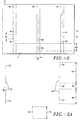
- the write heads 46 and 52 include gaps 66 and 68 respectively, separating the write head 46 into a lower write head 70 and an upper write head 72, and likewise separating the write head 52 into a lower write head 74 and an upper write head 76.
- the write head 46 may be manufactured by methods known in the art as a single core having a gap 66; alternatively, it may be manufactured as two separate cores 70 and 72.
- the write head 52 may be similarly manufactured.
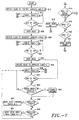
- servo blocks 140 previously recorded in track 136 reside in the path of the write head 46.
- the lateral position of the lower edges 156 of the servo .blocks 140 depend on the lateral position at which the previous track 148 was written.
- writing is disabled (B42).
- the lower edge 156 of the servo block 140 was laterally positioned during the writing of track 148.
- servo information could be alternately be provided in the headers of data blocks written on the tape.
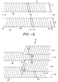
- the head 22 can be stepped 2.5 millinches (63.5 mm) between tracks 136 and 148, while the head 22 is stepped 1.5 millinches (38.1 mm) between all successive tracks.
Description
Claims (9)
- A method of writing information on a magnetic medium (12) comprising the steps of:writing (B12) alternate data (38) and servo (40) information in a first longitudinal track (136) on the magnetic medium at a first azimuth angle (+), the first longitudinal track including a longitudinal gap (142) such that the first longitudinal track comprises a first lateral portion (144) and a second lateral portion (146); andwriting (B30) alternate data and servo information in a second longitudinal track (148) on the magnetic medium at a second azimuth angle (-), the second longitudinal track including a longitudinal gap (150), such that the second longitudinal track comprises a first lateral portion (152) and a second lateral portion (154), the second track being written over the first track such that the first lateral portion (144) of the first track (136) remains on the tape, the longitudinal gap (150) in the second track (148) being positioned such that the alternate data (38) and servo (40) information written in the second lateral portion (146) of the first track (136) is exposed by the longitudinal gap (150) in the second track (148).
- The method of claim 1 further comprising the steps of:writing (B38) alternate data (38) and servo (40) information in a third longitudinal track (160) on the magnetic medium at the first azimuth angle (+), the third longitudinal track including a longitudinal gap such that the third longitudinal track comprises a first lateral portion and a second lateral portion, the third track being written over the second track (148) such that part of the first lateral portion (152) of the second track remains on the tape, and such that the lower portion of the third track (160) is written at a lateral position overlapping the second lateral portion (154) of the first track;interrupting writing (B42) at a position coinciding with servo information (140) from the first track (136);reading the amplitude of servo information;supplying a reference amplitude indicating a predetermined lateral relationship between tracks;comparing (B44, B48) the amplitude of servo information with the reference amplitude; andadjusting (B46, B50) the lateral position of writing in the third track in response to the comparison when said comparison falls outside a tolerance differential (ε) about the reference amplitude to bring the third track (160) into the predetermined lateral relationship with the second track (148).
- The method of claim 2 wherein the step of adjusting (B46, B50) adjusts the lateral position of writing in the third track (160) to bring the third track into an abutting relationship with the second track (148).
- Apparatus for writing information on a magnetic medium (12) comprising:means (22,66) for writing alternate data (38) and servo (40) information in a first longitudinal track (136) on the magnetic medium at a first azimuth angle (+), the first longitudinal track including a longitudinal gap (142) such that the first longitudinal track comprises a first lateral portion (144) and a second lateral portion (146); andmeans (22,66) for writing alternate data and servo information in a second longitudinal track (148) on the magnetic medium at a second azimuth angle (-), the second longitudinal track including a longitudinal gap (150) such that the second longitudinal track comprises a first lateral portion (152) and a second lateral portion (154), the second track being written over the first track such that the first lateral portion (144) of the first track (136) remains on the tape, the longitudinal gap (150) in the second track (148) being positioned such that the alternate data (38) and servo (40) information written in the second lateral portion (146) of the first track (136) is exposed by the longitudinal gap (150) in the second track (148).
- The apparatus of claim 4 further comprising:means for writing alternate data (38) and servo (40) information in a third longitudinal track (160) on the magnetic medium at the first azimuth angle (+), the third longitudinal track including a longitudinal gap such that the third longitudinal track comprises a first lateral portion and a second lateral portion, the third track being written over the second track (148) such that part of the first lateral portion (152) of the second track remains on the tape, and such that the lower portion of the third track (160) is written at a lateral position overlapping the second lateral portion of the first track;means (110,112) for interrupting writing (B42) at a position coinciding with servo information (140) from the first track (136);means (114,118) for reading the amplitude of servo information;means for supplying a reference amplitude indicating a predetermined lateral relationship between tracks;means for comparing the amplitude of servo information with the reference amplitude; andmeans (120,68) for adjusting the lateral position of writing in the third track in response to the comparison when said comparison falls outside a tolerance differential ε about the reference amplitude to bring the third track (160) into the predetermined lateral relationship with the second track (148).
- The apparatus of claim 5 wherein the means (120,68) for adjusting adjusts the lateral position of writing in the third track (160) to bring the third track into an abutting relationship with the second track (148).
- The apparatus of claim 4 further including:means (58,60) for reading following the means for writing, the means for reading laterally positioned to overlap part of the longitudinal track;means (120,68) for adjusting the lateral position of the means for writing in a first lateral direction when the means for reading reads data having a signal strength greater than a reference signal strength plus a tolerance value; andmeans (120,68) for adjusting the lateral position of the means for writing in the opposite lateral direction when the means for reading reads data having a signal strength less than a reference signal strength plus a tolerance value.
- The apparatus of claim 7 wherein the means for writing is a write head (50,52) on a magnetic head 22, and wherein the means for reading is a read head (58,60) on the magnetic head (22), the read head being positioned on the magnetic head such that the read head is laterally spaced from the write head and the length of the read head partially overlaps the length of the write head.
- The method of claim 1 further comprising:immediately following the of writing of alternate data and servo information, laterally positioning a read head to overlap part of the written longitudinal track;adjusting (B46) the lateral position of a means for writing said longitudinal tracks in a first lateral direction when the read head reads data having a signal strength greater than a reference signal strength plus a tolerance value; andadjusting (B50) the lateral position of the means for writing said longitudinal tracks in the opposite lateral direction when the read head reads data having a signal strength less than a reference signal strength plus a tolerance value.
Applications Claiming Priority (3)
| Application Number | Priority Date | Filing Date | Title |
|---|---|---|---|
| US26547694A | 1994-06-24 | 1994-06-24 | |
| US265476 | 1994-06-24 | ||
| PCT/US1995/008910 WO1996000442A1 (en) | 1994-06-24 | 1995-06-23 | Tape write servo |
Publications (3)
| Publication Number | Publication Date |
|---|---|
| EP0722604A1 EP0722604A1 (en) | 1996-07-24 |
| EP0722604A4 EP0722604A4 (en) | 1997-02-12 |
| EP0722604B1 true EP0722604B1 (en) | 2001-12-05 |
Family
ID=23010597
Family Applications (1)
| Application Number | Title | Priority Date | Filing Date |
|---|---|---|---|
| EP95926704A Expired - Lifetime EP0722604B1 (en) | 1994-06-24 | 1995-06-23 | Tape write servo |
Country Status (5)
| Country | Link |
|---|---|
| EP (1) | EP0722604B1 (en) |
| JP (1) | JPH09502563A (en) |
| KR (1) | KR960704314A (en) |
| DE (1) | DE69524375T2 (en) |
| WO (1) | WO1996000442A1 (en) |
Cited By (1)
| Publication number | Priority date | Publication date | Assignee | Title |
|---|---|---|---|---|
| CN110910907A (en) * | 2018-09-18 | 2020-03-24 | 株式会社东芝 | Magnetic disk apparatus and control method thereof |
Families Citing this family (2)
| Publication number | Priority date | Publication date | Assignee | Title |
|---|---|---|---|---|
| US6108159A (en) * | 1997-07-14 | 2000-08-22 | Quantum Corporation | Data track edge follower servo method and apparatus |
| JP5315399B2 (en) * | 2011-11-14 | 2013-10-16 | 日立マクセル株式会社 | Magnetic tape |
Citations (1)
| Publication number | Priority date | Publication date | Assignee | Title |
|---|---|---|---|---|
| US5257148A (en) * | 1989-05-30 | 1993-10-26 | Tandberg Data As | Method and apparatus for positioning a magnetic head in a magnetic layer memory system using tracking by reading a spaced pair of corresponding subtracks |
Family Cites Families (4)
| Publication number | Priority date | Publication date | Assignee | Title |
|---|---|---|---|---|
| US4472750A (en) * | 1981-07-02 | 1984-09-18 | Irwin Magnetic Systems, Inc. | Data record with pre-recorded transducer positioning signals, and system for utilizing same |
| JPS58203620A (en) * | 1982-05-21 | 1983-11-28 | Fujitsu Ltd | Data surface servo system |
| US5055951A (en) * | 1989-03-10 | 1991-10-08 | Irwin Magnetic Systems, Inc. | Method and apparatus for servo-positioning movable transducer heads |
| US5132861A (en) * | 1989-10-02 | 1992-07-21 | Behr Michael I | Systems using superimposed, orthogonal buried servo signals |
-
1995
- 1995-06-23 KR KR1019960700920A patent/KR960704314A/en not_active Application Discontinuation
- 1995-06-23 WO PCT/US1995/008910 patent/WO1996000442A1/en active IP Right Grant
- 1995-06-23 JP JP8503505A patent/JPH09502563A/en active Pending
- 1995-06-23 DE DE69524375T patent/DE69524375T2/en not_active Expired - Fee Related
- 1995-06-23 EP EP95926704A patent/EP0722604B1/en not_active Expired - Lifetime
Patent Citations (1)
| Publication number | Priority date | Publication date | Assignee | Title |
|---|---|---|---|---|
| US5257148A (en) * | 1989-05-30 | 1993-10-26 | Tandberg Data As | Method and apparatus for positioning a magnetic head in a magnetic layer memory system using tracking by reading a spaced pair of corresponding subtracks |
Cited By (1)
| Publication number | Priority date | Publication date | Assignee | Title |
|---|---|---|---|---|
| CN110910907A (en) * | 2018-09-18 | 2020-03-24 | 株式会社东芝 | Magnetic disk apparatus and control method thereof |
Also Published As
| Publication number | Publication date |
|---|---|
| DE69524375T2 (en) | 2002-08-14 |
| JPH09502563A (en) | 1997-03-11 |
| KR960704314A (en) | 1996-08-31 |
| DE69524375D1 (en) | 2002-01-17 |
| WO1996000442A1 (en) | 1996-01-04 |
| EP0722604A1 (en) | 1996-07-24 |
| EP0722604A4 (en) | 1997-02-12 |
Similar Documents
| Publication | Publication Date | Title |
|---|---|---|
| EP0715758B1 (en) | Tape servo using azimuth servo blocks | |
| US5307217A (en) | Magnetic head for very high track density magnetic recording | |
| US5371638A (en) | Servo method and apparatus for very high track density magnetic recording by adjusting head position based on servo information read from adjacent track | |
| US5949604A (en) | Method of writing and reading servo on tracks having a longitudinal gap | |
| EP0702823B1 (en) | Apparatus and method for distorted track data recovery | |
| US5488525A (en) | Decoupled magnetic head assembly for quarter-inch tape | |
| US6141174A (en) | Method of reading recorded information from a magnetic tape that compensates for track pitch changes | |
| US6108159A (en) | Data track edge follower servo method and apparatus | |
| EP0500760B1 (en) | Servo tracking for helical scan recorder | |
| EP0428325B1 (en) | Positioning separate read and write heads in a disk file | |
| US6545837B1 (en) | Method and apparatus for servo controlled azimuth data recording | |
| US5426543A (en) | Servo positioning system for magnetic recording media | |
| US6043951A (en) | Method, apparatus, and magnetic disk for optimizing off-track position of a magnetoresistive head | |
| US5276566A (en) | Recording/reading high density data tracks with backward compatibility | |
| EP1526514A1 (en) | Methods and systems for magnetic recording | |
| US5680269A (en) | Method and apparatus for controlling media linear speed in a helical scan recorder by reading servo information just after writing the servo information | |
| US7564637B2 (en) | Storage media having areas for storing data for correcting servo information errors | |
| US6134072A (en) | Tracking of non-native stripes in helical scan tape drive | |
| US7092187B2 (en) | Magnetic recording and reproducing apparatus and method and thin film magnetic head used therein | |
| US6101060A (en) | Method and apparatus for reducing data loss errors in a magnetic tape device | |
| EP0722604B1 (en) | Tape write servo | |
| JP2524319B2 (en) | Magnetic recording method with extremely high track density | |
| US5739973A (en) | Apparatus for recording a mixed video and tracking signal on a magnetic recording medium | |
| US6031682A (en) | Track trimming and orthogonal recording for cartridge tape | |
| JP2956349B2 (en) | Magnetic recording / reproducing device |
Legal Events
| Date | Code | Title | Description |
|---|---|---|---|
| PUAI | Public reference made under article 153(3) epc to a published international application that has entered the european phase |
Free format text: ORIGINAL CODE: 0009012 |
|
| AK | Designated contracting states |
Kind code of ref document: A1 Designated state(s): DE FR GB NL |
|
| 17P | Request for examination filed |
Effective date: 19960702 |
|
| A4 | Supplementary search report drawn up and despatched |
Effective date: 19961220 |
|
| AK | Designated contracting states |
Kind code of ref document: A4 Designated state(s): DE FR GB NL |
|
| 17Q | First examination report despatched |
Effective date: 19990601 |
|
| GRAG | Despatch of communication of intention to grant |
Free format text: ORIGINAL CODE: EPIDOS AGRA |
|
| GRAG | Despatch of communication of intention to grant |
Free format text: ORIGINAL CODE: EPIDOS AGRA |
|
| GRAH | Despatch of communication of intention to grant a patent |
Free format text: ORIGINAL CODE: EPIDOS IGRA |
|
| GRAH | Despatch of communication of intention to grant a patent |
Free format text: ORIGINAL CODE: EPIDOS IGRA |
|
| RAP1 | Party data changed (applicant data changed or rights of an application transferred) |
Owner name: QUANTUM CORPORATION |
|
| GRAA | (expected) grant |
Free format text: ORIGINAL CODE: 0009210 |
|
| AK | Designated contracting states |
Kind code of ref document: B1 Designated state(s): DE FR GB NL |
|
| PG25 | Lapsed in a contracting state [announced via postgrant information from national office to epo] |
Ref country code: NL Free format text: LAPSE BECAUSE OF FAILURE TO SUBMIT A TRANSLATION OF THE DESCRIPTION OR TO PAY THE FEE WITHIN THE PRESCRIBED TIME-LIMIT Effective date: 20011205 |
|
| REG | Reference to a national code |
Ref country code: GB Ref legal event code: IF02 |
|
| REF | Corresponds to: |
Ref document number: 69524375 Country of ref document: DE Date of ref document: 20020117 |
|
| NLV1 | Nl: lapsed or annulled due to failure to fulfill the requirements of art. 29p and 29m of the patents act | ||
| PLBE | No opposition filed within time limit |
Free format text: ORIGINAL CODE: 0009261 |
|
| STAA | Information on the status of an ep patent application or granted ep patent |
Free format text: STATUS: NO OPPOSITION FILED WITHIN TIME LIMIT |
|
| 26N | No opposition filed | ||
| PG25 | Lapsed in a contracting state [announced via postgrant information from national office to epo] |
Ref country code: FR Free format text: LAPSE BECAUSE OF NON-PAYMENT OF DUE FEES Effective date: 20030228 |
|
| REG | Reference to a national code |
Ref country code: FR Ref legal event code: ST |
|
| PGFP | Annual fee paid to national office [announced via postgrant information from national office to epo] |
Ref country code: DE Payment date: 20080630 Year of fee payment: 14 |
|
| PGFP | Annual fee paid to national office [announced via postgrant information from national office to epo] |
Ref country code: GB Payment date: 20080506 Year of fee payment: 14 |
|
| GBPC | Gb: european patent ceased through non-payment of renewal fee |
Effective date: 20090623 |
|
| PG25 | Lapsed in a contracting state [announced via postgrant information from national office to epo] |
Ref country code: GB Free format text: LAPSE BECAUSE OF NON-PAYMENT OF DUE FEES Effective date: 20090623 |
|
| PG25 | Lapsed in a contracting state [announced via postgrant information from national office to epo] |
Ref country code: DE Free format text: LAPSE BECAUSE OF NON-PAYMENT OF DUE FEES Effective date: 20100101 |