EP0267771A2 - Dual track servo system - Google Patents
Dual track servo system Download PDFInfo
- Publication number
- EP0267771A2 EP0267771A2 EP87309902A EP87309902A EP0267771A2 EP 0267771 A2 EP0267771 A2 EP 0267771A2 EP 87309902 A EP87309902 A EP 87309902A EP 87309902 A EP87309902 A EP 87309902A EP 0267771 A2 EP0267771 A2 EP 0267771A2
- Authority
- EP
- European Patent Office
- Prior art keywords
- head
- heads
- track
- data
- transducers
- Prior art date
- Legal status (The legal status is an assumption and is not a legal conclusion. Google has not performed a legal analysis and makes no representation as to the accuracy of the status listed.)
- Withdrawn
Links
- 230000009977 dual effect Effects 0.000 title 1
- 238000012937 correction Methods 0.000 claims abstract description 17
- 238000013500 data storage Methods 0.000 claims description 2
- 230000000712 assembly Effects 0.000 claims 1
- 238000000429 assembly Methods 0.000 claims 1
- 230000002457 bidirectional effect Effects 0.000 claims 1
- 230000000875 corresponding effect Effects 0.000 description 7
- 238000004364 calculation method Methods 0.000 description 3
- 238000000034 method Methods 0.000 description 3
- 230000004075 alteration Effects 0.000 description 1
- 230000001276 controlling effect Effects 0.000 description 1
- 238000010586 diagram Methods 0.000 description 1
- 238000006073 displacement reaction Methods 0.000 description 1
- 230000000694 effects Effects 0.000 description 1
- 238000012986 modification Methods 0.000 description 1
- 230000004048 modification Effects 0.000 description 1
Images
Classifications
-
- G—PHYSICS
- G11—INFORMATION STORAGE
- G11B—INFORMATION STORAGE BASED ON RELATIVE MOVEMENT BETWEEN RECORD CARRIER AND TRANSDUCER
- G11B21/00—Head arrangements not specific to the method of recording or reproducing
- G11B21/02—Driving or moving of heads
- G11B21/10—Track finding or aligning by moving the head ; Provisions for maintaining alignment of the head relative to the track during transducing operation, i.e. track following
-
- G—PHYSICS
- G11—INFORMATION STORAGE
- G11B—INFORMATION STORAGE BASED ON RELATIVE MOVEMENT BETWEEN RECORD CARRIER AND TRANSDUCER
- G11B5/00—Recording by magnetisation or demagnetisation of a record carrier; Reproducing by magnetic means; Record carriers therefor
- G11B5/48—Disposition or mounting of heads or head supports relative to record carriers ; arrangements of heads, e.g. for scanning the record carrier to increase the relative speed
- G11B5/54—Disposition or mounting of heads or head supports relative to record carriers ; arrangements of heads, e.g. for scanning the record carrier to increase the relative speed with provision for moving the head into or out of its operative position or across tracks
- G11B5/55—Track change, selection or acquisition by displacement of the head
- G11B5/5521—Track change, selection or acquisition by displacement of the head across disk tracks
- G11B5/5526—Control therefor; circuits, track configurations or relative disposition of servo-information transducers and servo-information tracks for control thereof
- G11B5/553—Details
- G11B5/5547—"Seek" control and circuits therefor
Definitions
- This invention relates to control systems and methods for translating a transducer relative to a disc, and more particularly to methods and apparatus for moving a transducers relative to a rotating disc and achieving more accurate registration between the transducer and the disc in a structure wherein a plurality of heads are being aligned with tracks on a stack of discs.
- the information is recorded in serial digital form on each face of a disc along a plurality of concentric circular tracks laid down in the circular band between the outer edge of the disc and a central circular area.
- the tracks may be subdivided into sectors, so that it is possible to select a single segment of track as a storage area for recording or reading.
- transducer elements are positioned over vertically aligned tracks on the stack of discs.
- Rapid reading of the information sought is limited by the availability of means for rapid, accurate positioning of the magnetic transducer relative to the vertically aligned tracks on the stacks of discs that contain the information.
- read/write transducers are mounted facing one another on a pair of arms movable in a radial direction with respect to the disc and disposed in the form of a fork so as to operate on both sides of the disc.
- a plurality of such pairs of recording heads are provided, operating on and facing opposite sides of a stack of discs.
- Each transducer must be accurately positioned, both in a normal direction with respect to the surface of the disc and in a radial direction with respect to the axis of the disc.
- FIG 1 schematically depicts a group of discs and a corresponding group of data heads such as are typically used in a high capacity disc drive. If the gaps of the recording heads are arranged on a line designated as HB-HT, they would record information or data on the discs which would ideally form another line DB-DT. The two lines should be coincident with each other.
- the disc drive unit receives from the computer an indication of the track in which the information sought is located.
- the disc drive unit must be able to execute the order of the computer by positioning the transducers over the track addressed, and thereafter be able to perform the function of reading or writing (or possibly erasure) which the processor transmits to it.
- the recorded data can become displaced from the data heads.
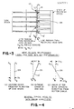
- FIG 2. The error is emphasized the higher the stack of discs, and the closer the tracks are aligned radially on the disc.
- the resulting displacement of the recorded data and the head which is trying to read the data represents an error.
- the maximum error is known as ⁇ E in the subject figure.
- Disc drives often use a servo head to measure the error of the type exemplified in FIG 2 and then correcting for it by moving the heads a corresponding amount.
- a single servo head is used located at the middle or at one extreme of the disc stack. This solution works well if the error is uniform from one end to the other of the disc stack as shown in FIG 2A.
- FIGs 2B and 2C When a tilting, or non-parallel condition exists, as shown in FIGs 2B and 2C, errors still occur, even after the servo head applies its correction. For example, assume the servo head was at the bottom of the disc stack and the condition shown in FIG 2B occurred. No error would be detected by the servo head and no correction would be applied. However, a significant error would exist at the top of the disc stack, resulting in reading or writing data from a track that differed dramatically from that actually addressed.
- One objective of this invention is to provide a novel apparatus for positioning a data transducer relative to a rotating data storage medium.
- Another objective is to provide an improved servo control system for accurately aligning a stack of transducer heads with vertically aligned tracks on a stack of discs.
- Yet another objective is to provide an accurate servo control system especially useful in aligning a stack of transducer heads with discs having data recorded at high data track densities.
- Another objective herein is to provide a unique method an apparatus for driving a transducer carriage to rapidly move a stack of transducer heads radially across data tracks during track seeking operations and aligning the stack of heads with the tracks for reading and writing operations.
- Another objective is to provide a unique servo control system which adjusts for relative tilt between a stack of transducer read/write heads and the vertically aligned tracks with which they are to be aligned for reading and writing operations, so that the error between any single head and the track with which it is to cooperate can be effectively eliminated.
- Yet another objective of this invention is to adjust the positioning of a stack of read/write heads relative to a vertical set of data tracks so that the error is relatively proportioned from the top to the bottom of the stack, whereby the error is at a minimum at the center of the stack, and varies to a maximum at the top and bottom of the stack so that in every case, the error at the extreme ends of the transducer stack is minimized.
- a plurality of discs in a stack are accessed using a vertical head array including two servo heads, one located at each end of the disc stack.
- two servo heads are provided, one located at each end of the disc stack.
- the error distance of the given head relative to the track can be determined by combining proportions of the two servo head signals from the top and bottom servo heads, their proportions being based on the vertical distance of each of the servo heads from the given head which is to be exactly centered over a track.
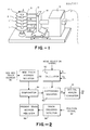
- FIG 1 is a perspective view schematically illustrating a mechanical portion of the typical magnetic disc storage apparatus accessing multiple discs with a plurality of magnetic heads.
- reference numbers 11 indicate a plurality of magnetic discs.
- the top and bottom discs may be servo discs.
- the stack of discs is fixed on a rotating shaft 12 rotated in the direction of arrow A.
- the shaft is rotated by an electric motor, not shown, at a constant high speed.
- the numbers 13 and 13 ⁇ indicate transducers, the number 13 ⁇ especially indicating a servo transducer which cooperates electromagnetically with the servo discs.
- the transducers 13 and 13 ⁇ are supported by a carriage 14 by means of corresponding arms 15 and are moved by the carriage 14 forward and backward in the directions of arrows B and B ⁇ . Accordinglyly, the transducers 13 and 13 ⁇ can travel in a radial direction relative to and slightly above or below the corresponding magnetic discs 11 and 11 ⁇ .
- a great amount of data stored is in a plurality of circular tracks (not shown) which are arranged concentrically on the disc.
- a control unit commands the readout of data from a particular track of a particular disc 11, or the writing of some data onto a particular track of a particular disc 11, the corresponding transducer 13 is moved to the desired track. Thereafter, transducer 13 can read out data from the desired track or write data onto the desired track.
- the above-mentioned movement of the transducers is accomplished by a linear motor 16 via the carriage 14 and arms 15.
- the fine positioning of the corresponding transducer to the desired track on the desired disc is made under control of servo information stored in tracks on the servo discs 11 ⁇ wherein servo information is read out by the servo transducer 13 ⁇ .
- the storage of servo data on separate discs or on sectors on data discs is well known, and will not be described in detail herein. It is sufficient to note for the purposes of this application wherein it is desired to compensate for potential tilt of a data transducer 11 located intermediate the top and bottom of vertical array of transducers 13, both the top and bottom discs contain servo information, and servo transducers are provided adjacent both these top and bottom surfaces of the disc stack.
- the servo information thus read out can be supplied to a controlling circuit and the control circuit controls the linear motor 16 so as to locate and hold the corresponding transducer on the desired track.
- the number 17 indicates a tachometer which detects the moving speed of the transducer, the detected moving speed being supplied to the control circuit to move the transducers with predetermined controlled speed.
- FIG 2 shows the essential elements of a control circuit that can be used to move a transducer to a desired disc track, in accordance with technology which is also well known in this art.
- a desired track address 30 is provided to a new track address register 32.
- This new track address is compared at comparator 34 with the present track address as stored in register 36.
- the present track address register 36 can be continually updated by a position signal 37 which comprises a signal received back from a detector coupled to the actuator motor 16 to provide a track crossing signal via track crossing detector 38.
- the resulting difference between the present track address from register 36 and the new track address from register 32 provides a signal to difference register 40, which can be converted 41 to a signal 42 to drive the actuator motor.
- the objective of this invention is to provide fine positioning to any data head in the vertical array of data heads relative to a track on any disc surface.
- the line HB-HT passing through the recording head gap should to inside with a line DB-DT which passes through vertically aligned data tracks on all of the discs.
- the head 13R is in fact exactly correctly located. However, the servo head would be located closer to one end or the other of the disc stack, with the result that some error would be perceived to be present, and a correction movement would occur, misaligning head 13R.
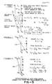
- a circuit 50 has been added to the position control electronics of FIG 2 to perform the calculations shown in FIG 5.
- the data error for any head can be calculated by providing two servo heads S1 and S2 preferably at the top and bottom of the stack of transducer heads, although for engineering reasons, they might be moved in slightly towards the center of the stack. If the selected data head 13R which is to be centered exactly over the track suffers from an error E c , this error can be broken down into two components.
- Equation 1 in FIG 5A provides for a calculation of the error at a given reading heads 13 so that it may be exactly centered over a desired reading track.
Abstract
Description
- This invention relates to control systems and methods for translating a transducer relative to a disc, and more particularly to methods and apparatus for moving a transducers relative to a rotating disc and achieving more accurate registration between the transducer and the disc in a structure wherein a plurality of heads are being aligned with tracks on a stack of discs.
- Owing to the capacity of modern electronic processors for processing large masses of information, large capacity stores for data and instructions must be provided. In other words, the need is clearly established for external stores, the capacity of which can be increased at will and in which searching and reading are rapid. These requirements are met by magnetic disc storage units, which typically in large mass storage situations include a cylindrical package of vertically stacked discs.
- In magnetic discs, the information is recorded in serial digital form on each face of a disc along a plurality of concentric circular tracks laid down in the circular band between the outer edge of the disc and a central circular area. The tracks may be subdivided into sectors, so that it is possible to select a single segment of track as a storage area for recording or reading. To accomplish this reading and recording, transducer elements are positioned over vertically aligned tracks on the stack of discs.
- Rapid reading of the information sought is limited by the availability of means for rapid, accurate positioning of the magnetic transducer relative to the vertically aligned tracks on the stacks of discs that contain the information.
- Normally, read/write transducers are mounted facing one another on a pair of arms movable in a radial direction with respect to the disc and disposed in the form of a fork so as to operate on both sides of the disc. In high capacity disc drives, a plurality of such pairs of recording heads are provided, operating on and facing opposite sides of a stack of discs. Each transducer must be accurately positioned, both in a normal direction with respect to the surface of the disc and in a radial direction with respect to the axis of the disc.
- The positioning of the transducer is generally carried out by electromechanical systems. It is obvious that the closer the tracks are brought to one another and the smaller the tolerance in the radial distance between two tracks (with a consequent greater amount of information recordable on the surface of the disc), the greater the problems that arise with the positioning mechanism. The mechanism must not only achieve a low time of access to the information sought, but must also effect precise positioning of the transducer over the desired track. FIG 1 schematically depicts a group of discs and a corresponding group of data heads such as are typically used in a high capacity disc drive. If the gaps of the recording heads are arranged on a line designated as HB-HT, they would record information or data on the discs which would ideally form another line DB-DT. The two lines should be coincident with each other.
- To position the transducers over the desired tracks, the disc drive unit receives from the computer an indication of the track in which the information sought is located. The disc drive unit must be able to execute the order of the computer by positioning the transducers over the track addressed, and thereafter be able to perform the function of reading or writing (or possibly erasure) which the processor transmits to it.
- However, due to dynamic and thermal disturbances which occur in disc drives, the recorded data can become displaced from the data heads. Several typical examples are diagrammed in FIG 2. The error is emphasized the higher the stack of discs, and the closer the tracks are aligned radially on the disc. The resulting displacement of the recorded data and the head which is trying to read the data represents an error. The maximum error is known as ΔE in the subject figure.
- Disc drives often use a servo head to measure the error of the type exemplified in FIG 2 and then correcting for it by moving the heads a corresponding amount. In known systems, a single servo head is used located at the middle or at one extreme of the disc stack. This solution works well if the error is uniform from one end to the other of the disc stack as shown in FIG 2A. When a tilting, or non-parallel condition exists, as shown in FIGs 2B and 2C, errors still occur, even after the servo head applies its correction. For example, assume the servo head was at the bottom of the disc stack and the condition shown in FIG 2B occurred. No error would be detected by the servo head and no correction would be applied. However, a significant error would exist at the top of the disc stack, resulting in reading or writing data from a track that differed dramatically from that actually addressed.
- One objective of this invention is to provide a novel apparatus for positioning a data transducer relative to a rotating data storage medium.
- Another objective is to provide an improved servo control system for accurately aligning a stack of transducer heads with vertically aligned tracks on a stack of discs.
- Yet another objective is to provide an accurate servo control system especially useful in aligning a stack of transducer heads with discs having data recorded at high data track densities.
- Another objective herein is to provide a unique method an apparatus for driving a transducer carriage to rapidly move a stack of transducer heads radially across data tracks during track seeking operations and aligning the stack of heads with the tracks for reading and writing operations.
- Another objective is to provide a unique servo control system which adjusts for relative tilt between a stack of transducer read/write heads and the vertically aligned tracks with which they are to be aligned for reading and writing operations, so that the error between any single head and the track with which it is to cooperate can be effectively eliminated.
- Yet another objective of this invention is to adjust the positioning of a stack of read/write heads relative to a vertical set of data tracks so that the error is relatively proportioned from the top to the bottom of the stack, whereby the error is at a minimum at the center of the stack, and varies to a maximum at the top and bottom of the stack so that in every case, the error at the extreme ends of the transducer stack is minimized.
- These and other objectives of this invention are achieved in a system wherein a plurality of discs in a stack are accessed using a vertical head array including two servo heads, one located at each end of the disc stack. In order to eliminate error due to relative tilting of the head stack relative to the discs, two servo heads are provided, one located at each end of the disc stack. In order to exactly center any given head over a desired track location in the disc stack, the error distance of the given head relative to the track can be determined by combining proportions of the two servo head signals from the top and bottom servo heads, their proportions being based on the vertical distance of each of the servo heads from the given head which is to be exactly centered over a track. If the servo distance is represented by S1 and S2, and the vertical distances from the head to the center of the servo heads is represented by Y1, Y2, then the general formula for calculating the error correction for centering the typical data head is Ec=1/Y1+Y2 × (S2Y1+S1Y2).
- The objectives and advantages of this invention can be best understood by reference to the following detailed description of the drawings wherein
- FIG 1 is a representation of the physical elements of the disc drive which the present system is meant to control;
- FIG 2 is a block diagram of a simple form of track seeking electronic circuitry;
- FIG 3 is an expanded schematic view of the head-to-data track relationship;
- FIG 4 illustrates several typical head-to-data track error condition situations; and
- FIG 5 illustrates a general case and two specific examples of the determination of data head error correction using two servo head schemes of this invention.
- FIG 1 is a perspective view schematically illustrating a mechanical portion of the typical magnetic disc storage apparatus accessing multiple discs with a plurality of magnetic heads. In FIG 1,
reference numbers 11 indicate a plurality of magnetic discs. In this figure, the top and bottom discs may be servo discs. The stack of discs is fixed on a rotatingshaft 12 rotated in the direction of arrow A. The shaft is rotated by an electric motor, not shown, at a constant high speed. Thenumbers 13 and 13ʹ indicate transducers, the number 13ʹ especially indicating a servo transducer which cooperates electromagnetically with the servo discs. Thetransducers 13 and 13ʹ are supported by acarriage 14 by means ofcorresponding arms 15 and are moved by thecarriage 14 forward and backward in the directions of arrows B and Bʹ. Accordingly, thetransducers 13 and 13ʹ can travel in a radial direction relative to and slightly above or below the correspondingmagnetic discs 11 and 11ʹ. - On each of the
discs 11, a great amount of data stored is in a plurality of circular tracks (not shown) which are arranged concentrically on the disc. When a control unit commands the readout of data from a particular track of aparticular disc 11, or the writing of some data onto a particular track of aparticular disc 11, thecorresponding transducer 13 is moved to the desired track. Thereafter,transducer 13 can read out data from the desired track or write data onto the desired track. The above-mentioned movement of the transducers is accomplished by alinear motor 16 via thecarriage 14 andarms 15. - The fine positioning of the corresponding transducer to the desired track on the desired disc is made under control of servo information stored in tracks on the servo discs 11ʹ wherein servo information is read out by the servo transducer 13ʹ. The storage of servo data on separate discs or on sectors on data discs is well known, and will not be described in detail herein. It is sufficient to note for the purposes of this application wherein it is desired to compensate for potential tilt of a
data transducer 11 located intermediate the top and bottom of vertical array oftransducers 13, both the top and bottom discs contain servo information, and servo transducers are provided adjacent both these top and bottom surfaces of the disc stack. The servo information thus read out can be supplied to a controlling circuit and the control circuit controls thelinear motor 16 so as to locate and hold the corresponding transducer on the desired track. The number 17 indicates a tachometer which detects the moving speed of the transducer, the detected moving speed being supplied to the control circuit to move the transducers with predetermined controlled speed. - FIG 2 shows the essential elements of a control circuit that can be used to move a transducer to a desired disc track, in accordance with technology which is also well known in this art. Basically, a desired
track address 30 is provided to a newtrack address register 32. This new track address is compared atcomparator 34 with the present track address as stored inregister 36. The present track address register 36 can be continually updated by aposition signal 37 which comprises a signal received back from a detector coupled to theactuator motor 16 to provide a track crossing signal viatrack crossing detector 38. The resulting difference between the present track address fromregister 36 and the new track address fromregister 32 provides a signal to difference register 40, which can be converted 41 to asignal 42 to drive the actuator motor. - The objective of this invention is to provide fine positioning to any data head in the vertical array of data heads relative to a track on any disc surface. Thus, referring to FIG 3, it can be seen that in the ideal situation the line HB-HT passing through the recording head gap should to inside with a line DB-DT which passes through vertically aligned data tracks on all of the discs.
- It can be seen from FIG 4 that a number of data error conditions can occur, which would result in differing error distances depending on which
head 13 was selected for reading. Thus, if ahead 13R near the approximate middle of the stack were selected for reading, and an error condition such a shown in FIG 2A occurred where the error is uniform from the top to the bottom of the disc stack, regardless of the location of thereading head 13R, relative to the servo head 13ʹ, the error would be corrected. However, if the error onhead 13R were less than the error detected at the head 13ʹ which might be part way up from the stack or even at the extreme end of the stack, as illustrated in FIG 4B, then either an over correction or no correction at all would occur. In the example of FIG 4C, thehead 13R is in fact exactly correctly located. However, the servo head would be located closer to one end or the other of the disc stack, with the result that some error would be perceived to be present, and a correction movement would occur, misaligninghead 13R. - In order to eliminate this problem and provide means for making corrections in all cases, a
circuit 50 has been added to the position control electronics of FIG 2 to perform the calculations shown in FIG 5. Specifically, the data error for any head can be calculated by providing two servo heads S1 and S2 preferably at the top and bottom of the stack of transducer heads, although for engineering reasons, they might be moved in slightly towards the center of the stack. If the selecteddata head 13R which is to be centered exactly over the track suffers from an error Ec, this error can be broken down into two components. A first component E1 can be calculated from the bottom servo error S1 according to the formula E1 = S1Y2/(Y1+Y2) where Y1 and Y2 are the vertical distances from the selectedhead 13R to the servo heads S1 and S2. The other component can be calculated from the servo distance error E2 using the formula E2 = S2Y1/Y1+Y2. Therefore, the accumulated error that must be calculated and corrected for is the sum of E1+E2 or S2Y1/(Y1+Y2)+S1Y2/(Y1+Y2). - The result of this calculation in exactly locating a
head 13R over the desired track without overcorrection as would otherwise occur is shown in examples 1 and 2. For example, if the tip of the head array is such that thecenter head 13R is in fact centered over the track to be read, but servo errors S1 and S2 are detected, then the accumulated error would be zero and no compensation would be made, although in cases using a single head, compensation would occur. Similarly, where the tilt is of the type shown in Example 2 and previously illustrated in FIG 2B, the correction to be applied to ahead 13R is 1/2 of the servo error S2. - Thus, the general formula known as
Equation 1 in FIG 5A provides for a calculation of the error at a given reading heads 13 so that it may be exactly centered over a desired reading track. - Alterations and modifications to this invention may occur to a person of skill in the art who studies the claimed invention disclosure. Therefore, the scope of this invention is to be limited only the following claims.
Claims (10)
a bidirectional mechanical rotor mounted in said frame adjacent said disc,
a head mounting structure securing said heads at one end thereof and secured to said rotor at the other end thereof for moving said heads across said multiplicity of concentric data tacks,
rotor driver means connected to said rotor for moving said head mounting structure and said heads each from a first departure track to a second destination track during track seeking operations,
first and second head position transducers mounted in said plurality of data transducer heads for providing track position signals, and
head controller means connected to head position transducers, said rotor driver and an external source of track selection information for calculating a track seeking command in response to known head position and said track selection information, for commanding said head to move from a known departure track to a requested destination track during a track seeking operation, and for correcting the position of said heads relative to said destination track based on head position data fed back from said pair of head position transducers.
Ec =
wherein
Y₁ is the vertical distance from a typical data head in said stack of data heads to a first of said head position transducers,
Y₂ is the vertical distance from said typical data head to the second of said head position transducers,
S₁ is the track error measured by the first of said transducers, and
S₂ is the track error measured by the second of said transducers.
an actuator motor having a movable armature,
a carriage transported by said actuator motor armature,
a vertical array of transducer head/arm assemblies supported by said carriage for movement adjacent the surfaces of said rotating discs, two of said transducer heads comprising first and second position transducer heads for detecting servo data, and
correction means coupled to said actuator motor and an external source of track selection information for calculating and position for said heads relative to one of said vertically aligned tracks based on said track selection information and said servo data fed back to said correction means from said pair of position transducer heads to minimize the distance of said head array from said tracks.
Ec =
wherein
Y₁ is the vertical distance from a typical data head in said stack of data heads to a first of said head position transducers,
Y₂ is the vertical distance from said typical data head to the second said head position transducers,
S₁ is the track error measured by the first of said transducers, and
S₂ is the track error measured by the second of said transducers.
Applications Claiming Priority (2)
| Application Number | Priority Date | Filing Date | Title |
|---|---|---|---|
| US92893486A | 1986-11-10 | 1986-11-10 | |
| US928934 | 1986-11-10 |
Publications (2)
| Publication Number | Publication Date |
|---|---|
| EP0267771A2 true EP0267771A2 (en) | 1988-05-18 |
| EP0267771A3 EP0267771A3 (en) | 1988-11-30 |
Family
ID=25457037
Family Applications (1)
| Application Number | Title | Priority Date | Filing Date |
|---|---|---|---|
| EP87309902A Withdrawn EP0267771A3 (en) | 1986-11-10 | 1987-11-09 | Dual track servo system |
Country Status (5)
| Country | Link |
|---|---|
| US (1) | US5555139A (en) |
| EP (1) | EP0267771A3 (en) |
| JP (1) | JP2778643B2 (en) |
| KR (1) | KR970004687B1 (en) |
| AU (1) | AU8091887A (en) |
Cited By (6)
| Publication number | Priority date | Publication date | Assignee | Title |
|---|---|---|---|---|
| EP0341362A2 (en) * | 1988-05-10 | 1989-11-15 | Mitsubishi Denki Kabushiki Kaisha | Magnetic disc apparatus |
| WO1991006952A2 (en) * | 1989-10-27 | 1991-05-16 | Unisys Corporation | Offset correction apparatus |
| EP0479701A2 (en) * | 1990-10-02 | 1992-04-08 | International Business Machines Corporation | Transducer head skew arrangement for disk drive system |
| EP0511863A2 (en) * | 1991-04-30 | 1992-11-04 | Fujitsu Limited | Magnetic disk drive units |
| US5477402A (en) * | 1992-05-08 | 1995-12-19 | International Business Machines Corporation | Disk file with multiplexed servo system |
| US5770630A (en) * | 1986-09-23 | 1998-06-23 | Foster Wheeler Energy Limited | Manufacture of organic liquids |
Families Citing this family (2)
| Publication number | Priority date | Publication date | Assignee | Title |
|---|---|---|---|---|
| US5935261A (en) * | 1997-06-05 | 1999-08-10 | International Business Machines Corporation | Method and apparatus for detecting handling damage in a disk drive |
| US9025274B1 (en) * | 2013-06-18 | 2015-05-05 | Marvell International Ltd. | Method and apparatus for writing to and reading from multiple drive heads |
Citations (4)
| Publication number | Priority date | Publication date | Assignee | Title |
|---|---|---|---|---|
| JPS5987669A (en) * | 1982-11-12 | 1984-05-21 | Hitachi Ltd | Head positioning system of magnetic disk device |
| JPS6126980A (en) * | 1984-07-18 | 1986-02-06 | Tokico Ltd | Magnetic disk device |
| JPS6199978A (en) * | 1984-10-19 | 1986-05-19 | Hitachi Ltd | Magnetic disk device |
| EP0233606A2 (en) * | 1986-02-14 | 1987-08-26 | Hewlett-Packard Company | Method and disc drive for compensating for information shifts on disc storage media |
Family Cites Families (18)
| Publication number | Priority date | Publication date | Assignee | Title |
|---|---|---|---|---|
| JPS49117007A (en) * | 1973-03-09 | 1974-11-08 | ||
| JPS5211564B2 (en) * | 1974-04-03 | 1977-03-31 | ||
| US3994016A (en) * | 1975-03-31 | 1976-11-23 | Honeywell Information Systems, Inc. | Head positioning servo system for disk drives |
| GB1503972A (en) * | 1975-07-24 | 1978-03-15 | Ibm | Data storage apparatus |
| JPS5813363B2 (en) * | 1977-07-07 | 1983-03-14 | オ−ツタイヤ株式会社 | Wheel |
| DE2759066A1 (en) * | 1977-12-30 | 1979-07-12 | Ibm Deutschland | DEVICE FOR REGULATING THE MAGNETIC HEAD POSITION DURING THE TRACK SELECTION AND THE TRACK SEQUENCE OF THE MAGNETIC HEAD OF A MAGNETIC DISC MEMORY |
| JPS54119215A (en) * | 1978-03-09 | 1979-09-17 | Toshiba Corp | Magnetic disc apparatus |
| JPS54158206A (en) * | 1978-06-05 | 1979-12-13 | Nec Corp | Servo-information recorder of magnetic disc memory |
| JPS54158207A (en) * | 1978-06-05 | 1979-12-13 | Nec Corp | Head offset controller of movable head type |
| JPS5564664A (en) * | 1978-11-09 | 1980-05-15 | Fujitsu Ltd | Magnetic disk unit |
| JPS5641562A (en) * | 1979-09-13 | 1981-04-18 | Fujitsu Ltd | Off-track correction system in magnetic disk unit |
| JPS573151A (en) * | 1980-06-05 | 1982-01-08 | Matsushita Electric Ind Co Ltd | Test system for 1-chip microcomputer |
| USRE32075E (en) * | 1980-09-24 | 1986-01-28 | Quantum Corporation | Data transducer position control system for rotating disk data storage equipment |
| US4377827A (en) * | 1980-11-10 | 1983-03-22 | Memorex Corporation | Servo positioning control system for a data storage apparatus |
| JPS5853060A (en) * | 1981-09-24 | 1983-03-29 | Fujitsu Ltd | Position signal detection circuit for sector servo system |
| JPS61151887A (en) * | 1984-12-26 | 1986-07-10 | Toshiba Corp | Disk memory device |
| JPS62129981A (en) * | 1985-11-30 | 1987-06-12 | Toshiba Corp | Magnetic recording and reproducing device |
| JPH0626025B2 (en) * | 1986-09-09 | 1994-04-06 | ティアツク株式会社 | Disk inclination detector |
-
1987
- 1987-11-09 AU AU80918/87A patent/AU8091887A/en not_active Abandoned
- 1987-11-09 EP EP87309902A patent/EP0267771A3/en not_active Withdrawn
- 1987-11-10 JP JP62284086A patent/JP2778643B2/en not_active Expired - Lifetime
- 1987-11-10 KR KR1019870012634A patent/KR970004687B1/en not_active IP Right Cessation
-
1995
- 1995-06-07 US US08/479,576 patent/US5555139A/en not_active Expired - Fee Related
Patent Citations (4)
| Publication number | Priority date | Publication date | Assignee | Title |
|---|---|---|---|---|
| JPS5987669A (en) * | 1982-11-12 | 1984-05-21 | Hitachi Ltd | Head positioning system of magnetic disk device |
| JPS6126980A (en) * | 1984-07-18 | 1986-02-06 | Tokico Ltd | Magnetic disk device |
| JPS6199978A (en) * | 1984-10-19 | 1986-05-19 | Hitachi Ltd | Magnetic disk device |
| EP0233606A2 (en) * | 1986-02-14 | 1987-08-26 | Hewlett-Packard Company | Method and disc drive for compensating for information shifts on disc storage media |
Non-Patent Citations (3)
| Title |
|---|
| PATENT ABSTRACTS OF JAPAN, vol. 10, no. 180 (P-471)[2236], 24th June 1986; & JP-A-61 26 980 (TOKICO LTD) 06-02-1986 * |
| PATENT ABSTRACTS OF JAPAN, vol. 10, no. 278 (P-499)[2334], 20th September 1986; & JP-A-61 99 978 (HITACHI LTD) 19-05-1986 * |
| PATENT ABSTRACTS OF JAPAN, vol. 8, no. 204 (P-301)[1641], 18th September 1984; & JP-A-59 87 669 (HITACHI SEISAKUSHO K.K.) 21-05-1984 * |
Cited By (12)
| Publication number | Priority date | Publication date | Assignee | Title |
|---|---|---|---|---|
| US5770630A (en) * | 1986-09-23 | 1998-06-23 | Foster Wheeler Energy Limited | Manufacture of organic liquids |
| EP0341362A2 (en) * | 1988-05-10 | 1989-11-15 | Mitsubishi Denki Kabushiki Kaisha | Magnetic disc apparatus |
| EP0341362A3 (en) * | 1988-05-10 | 1990-11-14 | Mitsubishi Denki Kabushiki Kaisha | Magnetic disc apparatus |
| WO1991006952A2 (en) * | 1989-10-27 | 1991-05-16 | Unisys Corporation | Offset correction apparatus |
| WO1991006952A3 (en) * | 1989-10-27 | 1991-07-11 | Unisys Corp | Offset correction apparatus |
| EP0479701A2 (en) * | 1990-10-02 | 1992-04-08 | International Business Machines Corporation | Transducer head skew arrangement for disk drive system |
| EP0479701A3 (en) * | 1990-10-02 | 1992-12-09 | International Business Machines Corporation | Transducer head skew arrangement for disk drive system |
| US5193036A (en) * | 1990-10-02 | 1993-03-09 | International Business Machines Corporation | Transducer head skew arrangement for disk drive system |
| EP0511863A2 (en) * | 1991-04-30 | 1992-11-04 | Fujitsu Limited | Magnetic disk drive units |
| EP0511863A3 (en) * | 1991-04-30 | 1993-02-10 | Fujitsu Limited | Magnetic disk drive units |
| US5321564A (en) * | 1991-04-30 | 1994-06-14 | Fujitsu Limited | Data head offset detecting circuit in magnetic disk unit and magnetic disk unit using said data head offset detecting circuit |
| US5477402A (en) * | 1992-05-08 | 1995-12-19 | International Business Machines Corporation | Disk file with multiplexed servo system |
Also Published As
| Publication number | Publication date |
|---|---|
| JPS63225979A (en) | 1988-09-20 |
| AU8091887A (en) | 1988-05-12 |
| JP2778643B2 (en) | 1998-07-23 |
| KR970004687B1 (en) | 1997-04-02 |
| KR880006690A (en) | 1988-07-23 |
| EP0267771A3 (en) | 1988-11-30 |
| US5555139A (en) | 1996-09-10 |
Similar Documents
| Publication | Publication Date | Title |
|---|---|---|
| US6292320B1 (en) | Disk drive with dual stage actuator radial offset calibration | |
| US5257149A (en) | Disc drive with offset address field | |
| US3924268A (en) | High density track follower control system for magnetic disk file | |
| EP0010664B1 (en) | Method and apparatus for positioning a transducing head | |
| US4924160A (en) | Staggered seeking method for disk drive sector servo | |
| US4019205A (en) | Disc drive with rotary access mechanism | |
| EP0264535A2 (en) | Shock and vibration disturbance compensation system for disc drives | |
| JPH08505488A (en) | Track servo control method in tape drive mechanism of data cartridge | |
| US5270886A (en) | Two motor servo system for a removable disk drive | |
| US5751512A (en) | Data storage format for data storage devices having a radial offset between read and write elements | |
| KR960001252B1 (en) | Transducer head skew arrangement for disk drive system | |
| US5091808A (en) | Two-motor servo mechanism system for a magnetic disk drive | |
| JP2583220B2 (en) | Compensation method for thermally induced track slip error in disk drive | |
| EP0267771A2 (en) | Dual track servo system | |
| US6967807B2 (en) | Selecting physical cylinders in a disc drive employing discs with pre-written servo patterns | |
| US4620243A (en) | Disk drive incremental rewrite | |
| JP2819153B2 (en) | Servo track writing method for magnetic disk drive | |
| US6118609A (en) | Method to adjust head switch time for improved disk drive performance | |
| JPH03272066A (en) | Method and device for writing servo-track | |
| JPH0594608A (en) | Magnetic disk device | |
| JPS62177772A (en) | Disk recording and reproducing device | |
| JPH0668896B2 (en) | Magnetic disk unit | |
| EP0994467B1 (en) | Head control unit in a disk apparatus | |
| JPS62137780A (en) | Magnetic disk device | |
| KR100284086B1 (en) | Servo track writer for hard disk drive and writing method of servo information |
Legal Events
| Date | Code | Title | Description |
|---|---|---|---|
| PUAI | Public reference made under article 153(3) epc to a published international application that has entered the european phase |
Free format text: ORIGINAL CODE: 0009012 |
|
| AK | Designated contracting states |
Kind code of ref document: A2 Designated state(s): AT BE CH DE ES FR GB GR IT LI LU NL SE |
|
| PUAL | Search report despatched |
Free format text: ORIGINAL CODE: 0009013 |
|
| AK | Designated contracting states |
Kind code of ref document: A3 Designated state(s): AT BE CH DE ES FR GB GR IT LI LU NL SE |
|
| 17P | Request for examination filed |
Effective date: 19890530 |
|
| 17Q | First examination report despatched |
Effective date: 19891004 |
|
| STAA | Information on the status of an ep patent application or granted ep patent |
Free format text: STATUS: THE APPLICATION IS DEEMED TO BE WITHDRAWN |
|
| 18D | Application deemed to be withdrawn |
Effective date: 19900418 |
|
| RIN1 | Information on inventor provided before grant (corrected) |
Inventor name: JACQUES, JAMES OLIVER |