EP0171266A2 - Recording digital information signals - Google Patents
Recording digital information signals Download PDFInfo
- Publication number
- EP0171266A2 EP0171266A2 EP85305502A EP85305502A EP0171266A2 EP 0171266 A2 EP0171266 A2 EP 0171266A2 EP 85305502 A EP85305502 A EP 85305502A EP 85305502 A EP85305502 A EP 85305502A EP 0171266 A2 EP0171266 A2 EP 0171266A2
- Authority
- EP
- European Patent Office
- Prior art keywords
- signal
- recording
- tracks
- tracking
- head
- Prior art date
- Legal status (The legal status is an assumption and is not a legal conclusion. Google has not performed a legal analysis and makes no representation as to the accuracy of the status listed.)
- Granted
Links
Images


Classifications
-
- G—PHYSICS
- G11—INFORMATION STORAGE
- G11B—INFORMATION STORAGE BASED ON RELATIVE MOVEMENT BETWEEN RECORD CARRIER AND TRANSDUCER
- G11B5/00—Recording by magnetisation or demagnetisation of a record carrier; Reproducing by magnetic means; Record carriers therefor
- G11B5/02—Recording, reproducing, or erasing methods; Read, write or erase circuits therefor
- G11B5/09—Digital recording
-
- G—PHYSICS
- G11—INFORMATION STORAGE
- G11B—INFORMATION STORAGE BASED ON RELATIVE MOVEMENT BETWEEN RECORD CARRIER AND TRANSDUCER
- G11B5/00—Recording by magnetisation or demagnetisation of a record carrier; Reproducing by magnetic means; Record carriers therefor
- G11B5/48—Disposition or mounting of heads or head supports relative to record carriers ; arrangements of heads, e.g. for scanning the record carrier to increase the relative speed
- G11B5/58—Disposition or mounting of heads or head supports relative to record carriers ; arrangements of heads, e.g. for scanning the record carrier to increase the relative speed with provision for moving the head for the purpose of maintaining alignment of the head relative to the record carrier during transducing operation, e.g. to compensate for surface irregularities of the latter or for track following
- G11B5/584—Disposition or mounting of heads or head supports relative to record carriers ; arrangements of heads, e.g. for scanning the record carrier to increase the relative speed with provision for moving the head for the purpose of maintaining alignment of the head relative to the record carrier during transducing operation, e.g. to compensate for surface irregularities of the latter or for track following for track following on tapes
- G11B5/588—Disposition or mounting of heads or head supports relative to record carriers ; arrangements of heads, e.g. for scanning the record carrier to increase the relative speed with provision for moving the head for the purpose of maintaining alignment of the head relative to the record carrier during transducing operation, e.g. to compensate for surface irregularities of the latter or for track following for track following on tapes by controlling the position of the rotating heads
- G11B5/592—Disposition or mounting of heads or head supports relative to record carriers ; arrangements of heads, e.g. for scanning the record carrier to increase the relative speed with provision for moving the head for the purpose of maintaining alignment of the head relative to the record carrier during transducing operation, e.g. to compensate for surface irregularities of the latter or for track following for track following on tapes by controlling the position of the rotating heads using bimorph elements supporting the heads
- G11B5/5921—Disposition or mounting of heads or head supports relative to record carriers ; arrangements of heads, e.g. for scanning the record carrier to increase the relative speed with provision for moving the head for the purpose of maintaining alignment of the head relative to the record carrier during transducing operation, e.g. to compensate for surface irregularities of the latter or for track following for track following on tapes by controlling the position of the rotating heads using bimorph elements supporting the heads using auxiliary signals, e.g. pilot signals
-
- C—CHEMISTRY; METALLURGY
- C07—ORGANIC CHEMISTRY
- C07F—ACYCLIC, CARBOCYCLIC OR HETEROCYCLIC COMPOUNDS CONTAINING ELEMENTS OTHER THAN CARBON, HYDROGEN, HALOGEN, OXYGEN, NITROGEN, SULFUR, SELENIUM OR TELLURIUM
- C07F9/00—Compounds containing elements of Groups 5 or 15 of the Periodic System
- C07F9/02—Phosphorus compounds
- C07F9/547—Heterocyclic compounds, e.g. containing phosphorus as a ring hetero atom
- C07F9/645—Heterocyclic compounds, e.g. containing phosphorus as a ring hetero atom having two nitrogen atoms as the only ring hetero atoms
- C07F9/6509—Six-membered rings
- C07F9/650952—Six-membered rings having the nitrogen atoms in the positions 1 and 4
-
- C—CHEMISTRY; METALLURGY
- C07—ORGANIC CHEMISTRY
- C07F—ACYCLIC, CARBOCYCLIC OR HETEROCYCLIC COMPOUNDS CONTAINING ELEMENTS OTHER THAN CARBON, HYDROGEN, HALOGEN, OXYGEN, NITROGEN, SULFUR, SELENIUM OR TELLURIUM
- C07F9/00—Compounds containing elements of Groups 5 or 15 of the Periodic System
- C07F9/02—Phosphorus compounds
- C07F9/547—Heterocyclic compounds, e.g. containing phosphorus as a ring hetero atom
- C07F9/6558—Heterocyclic compounds, e.g. containing phosphorus as a ring hetero atom containing at least two different or differently substituted hetero rings neither condensed among themselves nor condensed with a common carbocyclic ring or ring system
- C07F9/65583—Heterocyclic compounds, e.g. containing phosphorus as a ring hetero atom containing at least two different or differently substituted hetero rings neither condensed among themselves nor condensed with a common carbocyclic ring or ring system each of the hetero rings containing nitrogen as ring hetero atom
Definitions
- This invention relates to methods of and apparatus for recording digital information signals and, more particularly, to control of the tracking alignment of rotary heads during playback.
- tracking control for controlling the rotary head accurately to trace the recorded tracks upon playback is typically carried out by using a control signal that has been recorded by a fixed head along one edge of the magnetic tape in its width direction.
- This control signal is reproduced by the fixed head in the reproduction mode, and the reproduced control signal and the rotary phase of the rotary head are maintained in constant phase relation.
- This known tracking control method requires the use of a special fixed magnetic head, which is a disadvantage in compact equipment, because it requires its own mounting space in the recording and reproducing apparatus.
- a plurality of tracking control pilot signals are recorded in the longitudinal direction in each track to form a record region independent from the record region for the PCM signal.
- the recorded track is traced by a rotary head having a tracing width greater than the track width, and the tracking of the rotary head is controlled by the pilot signals reproduced from the tracks adjacent to the track being traced by the rotary head.
- a pulse signal (PG) having a frequency of 30 Hz is used that is indicative of the rotary phase of the head, and that is generated in synchronism with the rotation of the motor that drives the rotary head.
- the reference position of the pulse signal PG may be altered or displaced due to mechanical or electrical variations in the parameters of the apparatus, caused, for example, by changes in temperature, and such variations appear as a kind of tracking error constant (offset) upon playback.
- the sampling pulse that is used to reproduce the tracking pilot signal over one rotational period of the rotary head is formed with the pulse signal PG as a reference, the amount of error present therein becomes integrated, so as to be increased by so-called jitter, and the position of the sampling pulse is displaced in time.
- a method of recording digital signals on a record medium using a rotary head that periodically traces the record medium comprising:
- an apparatus for recording digital signals on a record medium using a rotary head that periodically traces the record medium comprising: means for recording a digital information signal at first predetermined areas in a plurality of oblique tracks formed on said record medium by said rotary head and forming the tracks by said rotary head with no guard bands between adjacent tracks; characterised by: means for determining second predetermined areas proximate to the end of the tracks and differing from said first predetermined areas; means for recording a tracking pilot signal in said second predetermined areas on the tracks, whereby said pilot signal is available for controlling tracking alignment of a playback head during reproduction of said information signal; means for determining predetermined positions in said second areas corresponding substantially to a centre portion of said pilot signal on an adjacent track; and means for recording an erase signal having various recording lengths at said predetermined position in said second predetermined areas.
- Figure 1 schematically shows a circuit arrangement of an embodiment of apparatus for recording a digital information signal and according to the present invention, in which only the parts of the circuit that are directly concerned with the present invention and that record and reproduce a tracking pilot signal, a position detecting signal and an erase signal, are shown.
- the tracking pilot signal and the erase signal are recorded and reproduced in the normal playback mode, as well as in a variable tape speed playback mode, such as when the tape speed is two or three times the normal tape speed.
- the circuit arrangement for recording and reproducing the information signal such as a PCM signal, for example, is omitted, because they form no part of the present invention.
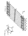
- rotary heads 1A and 1B are arranged in contact with a magnetic tape 2, which is used as the recording medium, and the rotary heads 1A and 1B are mounted on the periphery of a tape guide drum 3 and separated by an equal angular distance, namely, 180°, as shown in Figure 2.
- the tape 2 is wrapped around the outside of tape guide drum 3 at its peripheral portion over an angular distance of less than 180°, for example, an angular distance of 90°.
- the heads 1A and 1B are rotated at 30 revolutions per second (in a 30 field per second television system) in the direction shown by an arrow 4H, and the tape 2 is driven in the direction shown by an arrow 4T at a predetermined speed, so that oblique magnetic tracks 5A and 5B are respectively formed on the tape 2 one by one by the rotary heads 1A and 1B in a so-called overlapped writing state, as shown in Figure 3. That is, the width (tracing width) W of the head gap is selected to be greater than the track width.
- the width directions of the gaps of the rotary heads 1A and 1B are made different from each other relative to the direction perpendicular to their tracing direction.
- the so-called azimuth angles of the heads lA and 1B are selected to be different from each other to take advantage of the azimuth effect to cancel cross-talk.
- a pilot signal oscillator or generator 6 produces a tracking pilot signal P, which has a frequency fo selected to be, for example, about 200 KHz, and is recorded at a relatively high level. If the linearity between tracking phase displacement and a reproduced pilot signal output is ensured, the frequency fo of the tracking pilot signal P is desired to be a frequency presenting a relatively small amount of azimuth loss.
- Position detecting signal generators 7 and 8 produce position detecting signals S and T that will detect the position of the pilot signal P. These position detecting signals S and T are also used as an erase signal for the pilot signal P. This is because when new information is recorded on a tape 2 on which information was previously recorded, that previously recorded information being at the same time erased, it is not necessarily the case that the record tracks are identical in location to the previous corresponding record tracks, so the previously recorded pilot signal must be erased.
- the frequencies fl and f2 of the position detecting signals S and T are selected to be substantially different from the frequency fo of the pilot signal P, for example, about 700 kHz and 500 kHz, respectively. Also the recording levels thereof are selected to be such as in practice to erase the pilot signal P.
- An oscillator or generator 9 generates an erase signal EO.
- the erase signal EO is high in erase ratio relative to the signals P, S and T, when the pilot signal P and the position detecting signals S and T are written in an overlapping writing state.
- the frequency f3 of the erase signal EO is selected to be about 2 MHz.
- Recording waveform generators 10, 11, 12 and 13 respond to an edge portion, for example, a trailing edge, of a delay signal associated with a pulse PG, which will be described in detail in the following, and produces signals as follows.
- the recording waveform generator 10, on the basis of the pilot signal P from the pilot signal generator 6, produces the pilot signals which are arranged with a predetermined time interval tp (tp represents the recording time interval of the pilot signal and so on) in accordance with the number of pilot signals P to be recorded per track and the arrangement thereof in the track with a predetermined interval.
- An OR gate circuit 14 is provided logically to process the outputs from the generators 10 to 13.
- a switching circuit 15 is provided to change over the heads 1A and 1B, and is changed in position by a swtiching signal Sl ( Figure 4A) derived from a timing signal generator 16.
- the timing signal generator 16 is supplied with a pulse PG with a frequency of 30 Hz, which is indicative of the rotary phase of the heads 1A and 1B, from a pulse generator 17 in synchronism with the rotation of a motor 18 that drives the heads 1A and 1B.
- the pulse signal with a frequency of 30 Hz from the timing signal generator 16 derived from the pulse signal PG is supplied to a phase servo circuit 19 that produces a servo output by which the rotary phase of the motor 18 is controlled.
- the switching circuits 20A and 20B are connected to the contact R upon recording, whereas they are connectd to the contact P upon playback.
- An output signal S2 ( Figure 4D) from the timing signal generator 16 is supplied to a delay circuit 21 in which it is delayed with a delay time corresponding to the interval between the heads 1A and 1B, and the mounting position of the pulse generator 17.
- a delayed output signal S3 ( Figure 4E) from the delay circuit 21 is fed to each of recording timing generators 22 to 25.
- the switching signal Sl from the timing signal generator 16 is frequency-divided by two by a frequency divider 21' to become a signal S4 ( Figure 4C), which then is fed to the recording timing generators 23 to 25.
- the recording timing generators 22 to 25 generate timing signals which are used as recording references for the pilot signal and the like.
- the trailing edge of the signal S3 ( Figure 4E) delayed by the delay circuit 21 is made coincident with the time at which the first head lA or 1B comes into contact with the tape 2 during one rotation period.
- the recording timing generator 22 produces a pulse signal S5 ( Figure 4F) comprising pulses synchronized relative to the trailing edge of the signal S3 during the half rotation periods of one head 1A or 1B, for example, the half rotation periods of the head 1B, and pulses delayed by a time T + 3tp/2 (T represents the time corresponding to the half rotation periods of the head 1B) relative to the trailing edge of the signal S3 during the half rotation periods of the other head 1A.
- T represents the time corresponding to the half rotation periods of the head 1B
- Tl the durations of the pulses are tp.
- the recording timing generator 23 generates a pulse signal S6 ( Figure 4G) comprising pulses delayed by a time 3tp/2 relative to the trailing edge of the signal S3 only during the half rotation periods of one head 1A or 1B, for example, during only the half rotation periods of the head 1B.
- a pulse signal S6 ( Figure 4G) comprising pulses delayed by a time 3tp/2 relative to the trailing edge of the signal S3 only during the half rotation periods of one head 1A or 1B, for example, during only the half rotation periods of the head 1B.
- Tl time between these pulses and, for example, during the odd rotation periods of the head 1B, the durations of the pulses are tp/2, while during the even rotation periods of the head 1B, the durations of the pulses are tp/4.
- the recording timing generator 24 generates a pulse signal S7 ( Figure 4H) delayed relative to the trailing edge of the signal S3 by a time T, only during the half rotation periods of the other head 1A or 1B, for example, only the half rotation periods of the head lA.
- a pulse signal S7 Figure 4H
- T1 There is a predetermined interval T1 between these pulses, and where the durations of the pulses are tp/2 during the odd rotation periods of the head lA, the durations of the pulses are tp/4 during the even rotation periods of the head lA.
- the recording timing generator 25 generates the following signal S8. That is, in the odd rotation periods and during the half rotation period of the head 1B, there is generated a pair of pulses which are delayed by a time tp relative to the trailing edge of the signal S3 with an interval of time tp/2 therebetween and at a predetermined intereval Tl between pairs of pulses. Each of the pulses has a duration of tp/2.
- a pulse signal comprising pulses of duration tp delayed by a time T + tp/2 relative to the trailing edge of the signal S3. There is a predetermined interval Tl between these pulses.
- the signal S5 ( Figure 4F), the signal S6 ( Figure 4G), the signal S7 ( Figure 4H) and the signal S8 ( Figure 41) from the recording timing generators 22, 23, 24 and 25 are respectively supplied to the recording waveform generators 10, 11, 12 and 13 as their gate signals so that the pilot signal P, the position detecting signals S and T, and the erase signal EO from the generators 6, 7, 8 and 9 are respectively supplied through the recording waveform generators 10, 11, 12 and 13 to the OR gate circuit 14 as shown in Figure 1.
- they are developed at the output side thereof as a composed signal S9 ( Figure 4J).
- amplifiers 26A and 26B are respectively supplied with the playback outputs from the corresponding heads 1A and 1B when the switching circuits 20A and 20B are changed in position to their contacts P upon playback.
- the respective outputs of the amplifiers 26A and 26B are supplied to a switching circuit 27.
- the switching circuit 27 is alternately changed in position by a switching signal S'l ( Figure 5A) of 30 Hz from the timing signal generator 16 during the half rotation period including the tape contact period of the head 1A and during the half rotation period including the tape contact period of the head 1B similarly to the recording mode, respectively.
- a band-pass filter 28 of a narrow band having a centre pass frequency fo is provided to derive only the pilot signal P from the reproduced output of the switching circuit 27.
- An envelope detector 29 is provided to envelope- detect the output from the band-pass filter 28 and the output from the envelope detector 29 is sampled and then held by a sample-and-hold circuit 30.
- a comparator or differential amplifier 31 is provided to compare the outputs from the envelope detector 29 and the sample-and-hold circuit 30.
- a sample-and-hold circuit 32 is provided to sample and hold the compared error signal from the differential amplifier 31.
- the sample-and-hold circuits 30 and 32 function to sample and hold a cross-talk component of the pilot signals recorded on both end portions of the tracks adjacent to the track being traced upon normal playback mode as will be described later. Then, the output from the sample-and-hold circuit 32 is supplied to an output terminal 33 as a tracking control signal.
- band-pass filters 34 and 35 of narrow band having centre pass frequencies fl and f2 are provided at the output side of the switching circuit 27 which derive only the position detecting signals S and T from the reproduced output.
- Outputs S10 ( Figure 5E) and Sll ( Figure 5F) thereof are supplied through a switching circuit 36 to a comparator 37 which serves as a waveform shaping circuit.
- the switching circuit 36 is changed in position by the switching signal S'1 of 30 Hz from the timing signal generator 16.
- Sampling pulse generators 38 and 39 are provided at the output side of the comparator 37.
- the sampling pulse generator 38 generates a first sampling pulse SP1 (Figure 5G) in synchronism with the leading edge of the output from the comparator 37, whereas the sampling pulse generator 39 generates a second sampling pulse SP2 ( Figure 5H) with the delay of a predetermined time tp after the first sampling pulse SP1 was produced.
- These sampling pulses SPl and SP2 are supplied to the sample-and-hold circuits 30 and 32, respectively.
- the timing signal generator 16 Upon recording, in response to the pulse PG indicative of the rotary phases of the heads 1A and 18 derived from the pulse generator 17, the timing signal generator 16 produces the signal S2 shown in Figure 4D.
- the signal S2 is supplied to and delayed by a predetermined time by a delay circuit 21 and so the delay circuit 21 produces the signal S3 shown in Figure 4E.
- the signal S3 is supplied to the recording timing generators 22 to 25 so that the recording timing generator 22 produces at its output the signal S5 shown in Figure 4F.
- the switching signal Sl from the timing signal generator 16 is supplied to the frequency divider 21' so that the frequency divider 21' produces the signal S4 shown in Figure 4C.
- the signal S4 is supplied to the recording timing generators 23 to 25 whereby in response to the signals S3 and S4, the recording timing generators 23 to 25 produce the signals S6 to S8 shown in Figures 4G to 41, respectively.
- the signals S5, S6, S7 and S8 are respectively supplied to the recording waveform generators 10, 11, 12 and 13.
- the recording waveform generator 10 passes therethrough in synchronism with the signal S5 supplied thereto the pilot signal P from the pilot signal generator 6 at a predetermined interval and for a predetermined time tp as shown in Figure 4F
- the recording waveform generator 11 passes therethrough in synchronism with the signal S6 supplied thereto the position detecting signal S from the synch generator 7 at a predetermined interval and for a predetermined time as shown in Figure 4G
- the recording waveform generator 12 passes therethrough in synchronism with the signal S7 supplied thereto the position detecting signal T from the synch generator 8 at a predetermined interval and for a predetermined time as shown in Figure 4H
- the recording waveform generator 13 passes therethrough in synchronism with the signal S8 supplied thereto the erase signal EO from the synch generator 9 at a predetermined interval and for a predetermined time as shown in Figure 41.
- the head 1B records the track 5B1 in Figure 3 (in the first half period tB of Figure 4).
- the first and second pulses of the signal S5 in Figure 4F correspond to the pilot signals PA1 and PA2, respectively
- the first and second pulses of the signal S6 in Figure 4G correspond to the position detecting signals SAl and SA2, respectively
- the first and second pulses formed of a pair of pulses of the signal S8 in Figure 41 correspond to the erase signals EO which are adjacent to the two sides of the position detecting signals SA1 and SA2, respectively.
- the composed signals of the signals corresponding to the alignments of these signals namely, PA1, EO, SA1, EO and PA2, EO, SA2 and EO are produced at each group at the output side of the OR circuit 14.
- the head 1A records the track 5A2 in Figure 3 (in the first half period tA of Figure 4).
- the first and second pulses of the signal S5 in Figure 4F respectively correspond to the pilot signals PB3 and PB4
- the first and second pulses of the signal S7 in Figure 4H respectively correspond to the position detecting signals TB3 and TB4
- the first and second pulses of the signal S8 in Figure 41 respectively correspond to the erase signals EO which are adjacent to the side of the position detecting signals TB3 and TB4.
- the composed signals of the signals corresponding to the alignments of these signals namely, TB3, EO, PB3 and PB4, EO and PB4 are produced in each group at the output side of the OR circuit 14.
- the head 1B records the track 5B2 in Figure 3 (the second half period tB of Figure 4).
- the first and second pulses of the signal S5 in Figure 4F respectively correspond to the pilot signals PA3 and PA4
- the first and second pulses of the signal S6 in Figure 4G respectively correspond to the position detecting signals SA3 and SA4
- the first and second pulse formed of a pair of pulses of the signal S8 in Figure 41 respectively correspond to the erase signals EO which are adjacent to the respective sides of the position detecting signals SA3 and SA4.
- the composed signals of the signals corresponding to the alignment of these signals, namely, PA3, EO, SA3 and EO, and PA4, EO, SA4 and EO are produced at each group at the output side of the OR circuit 14.
- the head 1A records the track 5A3 in Figure 3 (the second half period tA of Figure 4).
- the first and second pulses of the signal S5 in Figure 4F correspond to the pilot signals PB5 and PB6, respectively
- the first and second pulses of the signal S7 in Figure 4H respectively correspond to the position detecting signals TB5 and TB6
- the first and second pulses of the signal S8 in Figure 41 respectively correspond to the erase signals EO which are adjacent to the sides of the position detecting signals TB5 and TB6.
- the composed signals of the signals corresponding to the alignments of these signals, namely, TB5, EO and PB5 and TB6, EO and PB6 are produced at each group at the output side of the OR circuit 14.
- the switching signal Sl as shown in Figure 4A in response to the pulse PG from the pulse generator 17.
- the signal Sl is in synchronism with the rotation of the heads 1A and 1B so that as shown in Figures 4A and 4B, during the half rotation period tA of the head 1A in which the signal Sl is at high level, the head 1A comes into contact with the tape 2, while during the half rotation period tB in which the signal Sl is at low level, the head 1B comes into contact with the tape 2.
- the switching circuit 15 is changed in position by the switching signal Sl to the state shown in Figure 1 during the period tA, while it is changed in position to the state opposite to that shown in the figure during the period tB, thus the head lA, 1B is changed over.
- the signal S9 obtained from the OR circuit 14 is supplied through the amplifier 19B and the contact R of the switching circuit 20B to the head 1B, whereby at the beginning and the end of the contact period of the head 1B with the tape 2 within the period tB and in record regions AT1 and AT2 for the tracking signal provided at the two end portions of the track 5B in its longitudinal direction distant from the centre position of the track 5B in its longitudinal direction by an equal length 1, the signal S9 is recorded in the odd rotation period of the head 1B (the first half period tB of Figure 4) for a time:
- the signal S9 is supplied through the amplifier 19A and the contact R of the switching circuit 20A to the head lA, whereby at the beginning and the end of the contact period of the head 1A with the tape 2 within the period tA and in the similar regions AT1 and AT2 provided in the two end portions of the track 5A in its longitudinal direction distant from the central position of the track 5A in its longitudinal direction by the equal distance 1, the signal S9 is recorded in the odd rotation period (the first half period tA of Figure 4) of the head 1A for the time:
- an audio PCM signal of one segment portion to be recorded as one track is supplied through the amplifier 19A to the head 1A during the period tA, while it is supplied through the amplifier 19B to the head 1B during the period tB so that they are recorded on the record region Apl other than the record regions of the above-described pilot signals of the respective tracks 5A and 5B.
- the motor 18 is applied with the phase servo from the phase servo circuit 19 similarly to the recording mode.
- the signals reproduced from the tape 2 by the heads 1A and 1B are respectively supplied through the contact P of the switching circuit 20A and the amplifier 26A and the contact P of the switching circuit 20B and the amplifier 26B to the switching circuit 27.
- the switching circuit 27 is alternately changed over by the switching signal S'l of 30 Hz as shown in Figure 5A from the timing signal generating circuit 16 at the half rotation period tA including the tape contact period of the head 1A and at the half rotation period tB including the tape contact period of the head 1B similarly to the recording mode. Accordingly, from the switching circuit 27 there is derived an intermittent PCM signal SR of one segment each as shown in Figure 5C.
- this PCM signal SR is supplied to a playback processor thereby to be demodulated to the original PCM signal and then further fed to a decoder in which a data of each block is detected by the block synchronizing signal, corrected for error and de-interleaved and then recoverted to the analog audio signal by a digital-to-analog converter and then fed to an output.
- the tracking control will be carried out as follows.
- the head 1B traces the range of a tracing width W including the track 5B1 as shown by one-dot chain lines in Figure 3, the head 1B traces also the tracks 5A2 and 5A1 which are adjacent to the track 5B1 so that as shown in Figure 3, in the region ATl, the pilot signal PA1 of the track 5B1, the pilot signal PB3 of the adjacent track 5A2 and the pilot signal PB1 of the adjacent track 5A1 are reproduced by the head 1B, while in the region AT2, the pilot signal PA2 of the track 5Bl, the pilot signal PB4 of the track 5A2 and the pilot signal PB2 of the adjacent track 5A1 are reproduced by the head 1B, respectively.
- the reproduced output of the head 1B derived from the switching circuit 27 is supplied to the band-pass filter 28 of narrow pass band having the pass centre frequency fo, which passes therethrough only the pilot signals as its output SF as shown in Figure 5D, and this output signal SF is fed to the envelope detector 29.
- the output SR of the switching circuit 27 is also supplied to the band-pass filters 34 and 35 of narrow pass bands having pass centre frequencies fl and f2, which pass therethrough the position detecting signals S10 and Sll as shown in Figures 5E and 5F, respectively.
- the signals S10 and Sll are respectively supplied to the switching circuit 36 from which the signal S10 is derived when the switching signal S'l is at low level, and the signal Sll when it is at high level, which then are fed to the comparator 37.
- the comparator 37 compares the signals S10 and Sll supplied thereto with a reference value, waveform-shapes them and supplies them to the sampling pulse generators 38 and 39.
- the sampling pulse generator 38 produces the first sampling pulse SP1 in synchronism with the rising edge of the waveform-shaped signal S10 as shown in Figure 5G and the first sampling pulse SPl is supplied to the sample-and-hold circuit 30.
- the sampling pulse SP1 makes the sample-and-hold circuit 30 sample the cross-talk components of the pilot signals PB3 and PB4 of the adjacent track 5A2 at the side opposite to the transportion direction of the tape 2 shown by an arrow 4T ( Figure 3) and the signal thus sampled is supplied to one input terminal of the differential amplifier 31 as the tracking signal of advanced phase.
- the cross-talk component of the pilot signals PBI and PB2 of the adjacent track 5A1 at the side of the tape transport direction is supplied to the other input terminals of the differential amplifier 31 from the envelope detector 29 at the tracking signals of delayed phase, respectively. Accordingly, the differential amplifier 31 compares the tracking signals corresponding to the cross-talk components of the pilot signals PB3 and PB1, and PB4 and PB2, in turn.
- the compared error signal from the differential amplifier 31 is supplied to the sample-and-hold circuit 32 in which it is sampled by the sampling pulse SP2 produced from the sampling pulse generator 39 after the time tp since the sampling pulse SP1 was produced. Consequently, from the sample-and-hold circuit 32, the difference between the two inputs to the differential amplifier 31 is produced as the tracking control signal.
- This tracking control signal is supplied from the output terminal 33 to a capstan motor (not shown) which then controls the amount of the tape 2 transported.
- the head 1B is controlled such that the level difference between the two inputs to the differential amplifier 31 becomes zero or when the head 1B traces the track 5B1, the head 1B traces the two tracks 5A2 and 5A1 at each side of the track 5B1 by the same amount. In other words, the head 1B is controlled to trace the track 5B1 such that the central position of the width direction of the gap of the head 1B is made coincident with the centre of the track 5B1.
- the heads 1A and 1B will be controlled similarly.
- the head 1A traces the track 5A2
- the cross-talk components of the pilot signals PA3 and PA4 are sampled by the sampling pulse SP1 supplied from the sampling pulse generator 38 to the sample-and-hold circuit 30 thereby to produce the tracking signal.
- This tracking signal is supplied to the differential amplifier 31 at the next stage, and the output corresponding to the cross-talk components of the pilot signals PA1 and PA2 and derived from the envelope detector 29 is supplied to the differential amplifier 31 in which the tracking signals respectively corresponding to the cross-talk components between the pilot signals PA3 and PA1, and PA4 and PA2 are compared with one another.
- the compared error signal is sampled by the sampling pulse SP2 which is supplied to the sample-and-hold circuit 32 so as to produce the tracking control signal for the head 1A.
- the cross-talk components of the pilot signals PB5 and PB6 and PB3 and PB4 of the adjacent tracks 5A3 and 5A2 are produced.
- the cross-talk components of the pilot signals PB5 and PB6 are sampled by the sampling pulse SP1
- the tracking signals corresponding to the cross-talk components of the pilot signals PB5 and PB3, and PB6 and PB4 are compared with one another by the differential amplifier 31.
- the compared error signal is sampled by the sampling pulse SP2 thereby to produce the tracking control signal for the head 1B.
- the head 1A traces the track 5A3, as shown in Figure 3, the cross-talk components of the pilot signals PA5 and PA6, and PA3 and PA4 of the two adjacent tracks 5B3 and 5B2 are produced.
- the cross-talk components of the pilot signals PA5 and PA6 are sampled by the sampling pulse SP1
- the tracking signals corresponding to the cross-talk components of the pilot signals PA5 and PA3, and PA6 and PA4 are controlled by the differential amplifier 31.
- the compared error signal is sampled by the sampling pulse SP2 thereby to produce the tracking control signal corresponding to the head lA.
- Figure 6 shows an example of a practical circuit arrangement of the sampling pulse generator 39 comprising a counter 40 for counting the pulses of the position detecting signal supplied thereto from the comparator 37.
- a data selector 41 is responsive to the signals S4 and S'l, and then selects the data (set values) of four kinds which are classified by the contents of the position detecting signals; namely, classified by the frequencies and the recording lengths of the position detecting signals S and T in this embodiment.
- a coincidence detecting circuit 42 detects whether the count value of the counter 40 coincides with the data of the data selector 41.
- the coincidence detecting circuit 42 there is used, for example, a digital comparator.
- Delay circuits 43 to 46 each derive a predetermined delay signal from the sampling pulse SP1.
- the counter 40 is enabled by the output from the delay circuit 44 and is then cleared by the output from the delay circuit 45.
- To an input terminal D of a flip-flop circuit 47 there is supplied the output from the coincidence detecting circuit 42.
- sampling pulse generator 39 shown in Figure 6 will be described with reference to the signal waveform diagrams of Figure 7.
- the sampling pulse generator 38 When a signal S13 as the position detecting signal, shown in Figure 7D is supplied from the comparator 37 to the sampling pulse generator 38, the sampling pulse generator 38 produces the sampling pulse SP1 in synchronism with the leading edge of the first pulse of the signal S13 shown in Figure 7H.
- the sampling pulse SP1 is supplied to the sample-and-hold circuit 30 ( Figure 1) and also to the delay circuits 43 to 46.
- the delay circuit 44 produces at its output side a signal S12 having a duration corresponding substantially to tp/2 in synchronism with the sampling pulse SP1 as shown in Figure 7C.
- the signal S12 is supplied to the counter 40 as the enable signal thereof.
- the counter 40 counts the pulse of the signal S13 from the comparator 37 during the period in which the signal S12 is at high level.
- the data selector 41 responds to the signals S'l and S4 which are respectively shown in Figures 7A and 7B and selects the data relating to the position detecting signal. If the selected data and the content of the counter 40 coincide with each other, the coincidence detecting circuit 42 produces at its output side a signal S14 which continues from the trailing edge of the final pulse of the signal S13 by a predetermined time as shown in Figure 7E. This signal S14 is supplied to the flip-flop circuit 47 as the data thereof.
- the delay circuit 46 produces a signal S15 in synchronism with the sampling pulse SP1 with a delay of a predetermined time 6tl therefrom as shown in Figure 7F.
- This signal S15 is supplied to the clock terminal CK of the flip-flop circuit 47, in which the signal S14 supplied to the input terminal D thereof is latched.
- the delay time 6tl of the delay circuit 46 is selected to satisfy the condition tp is greater than ⁇ t1 is greater than tp/2.
- the delay circuit 45 produces a signal S16 in synchronism with the sampling pulse SP1 and after therefrom by a predetermined time ⁇ t2 as shown in Figure 7G.
- This signal S16 is supplied to the counter 40 thereby to clear the content thereof and is also supplied to the flip-flop circuit 47 thereby to reset it.
- the flip-flop circuit 47 produces a signal S17 as shown in Figure 71.
- the delay time &t2 of the delay circuit 45 is selected so as to satisfy the condition ⁇ t2 is greater than tp.
- the delay circuit 43 produces a signal S18 in synchronism relative to the sampling pulse 5P1 a predetermined time tp thereafter as shown in Figure 7J.
- the signal S18 is supplied to one input terminal of the AND circuit 48. Since the AND circuit 48 is supplied at the other input terminal thereof with the signal S17 which is formed as described above, the signal S17 is supplied to the AND circuit 48 as its gate signal so that in response to the signal S18, the sampling pulse SP2 as shown in Figure 7K is produced.
- the sampling pulse SP2 is supplied to the sample-and-hold circuit 32.
- the sampling pulse SP2 can be produced.
- the sampling pulse SP2 can be produced by the data processing of a microcomputer (not shown), and this will now be described with reference to the flow chart of Figure 8.
- step 110 the program goes to step 110 in which the position detecting signals S and T are detected. If they are not detected, the detecting operation is repeated at step 110 until the position detecting signals S and T are detected. If the position detecting signals S and T are detected at step 110, the first sampling pulse SPl is produced on the basis of the position detecting signals S and T at step 120 and the pulse Ni of the first sampling pulse SP1 is counted only during the detection periods of the position detecting signals S and T at step 130.
- step 140 it is judged whether the detected position detecting signals S and T are those which are produced first in the playback mode or not. If they are the first ones, the program goes to step 150 in which it is judged whether the interval is the interval tp/2 or not and tp/4 or not. If the interval satisfies either of them, the program goes to step 160 in which the second sampling pulse SP2 is produced. If neither the tp/2 interval nor the tp/4 interval is satisfied at step 150, they are not the position detecting signals S and T so that the program returns to the step 110.
- step 140 If at step 140 it is judged that the position detecting signals S and T are ones which are produced in the second time after the apparatus was set in the playback mode, the program goes to step 170 in which it is judged whether the polarity of the signal S4 has changed or not. If the polarity of the signal S4 has changed, the program goes to step 180 in which it is judged whether the preceding detection interval is tp/2 or tp/4. If it is tp/2, the program goes further to step 190 in which it is judged whether the interval of the present position detecting signal is tp/4 or not. If it is tp/4, the position detecting signal is the true position detecting signal so that at step 160, the second sampling pulse SP2 is produced. If on the other hand it is not tp/4, the program returns to step 110.
- step 180 If it is judged that the preceding detecting interval is tp/4 at step 180, the program goes to step 200 in which it is judged whether the interval of the present position detecting signal is tp/2 or not. If it is tp/2, it is the true position detecting signal, so that the program returns to step 160 in which the second sampling pulse SP2 is produced. If on the other hand it is not tp/2, the program returns to step 110.
- step 170 if it is judged that the polarity of the signal S4 is changed at the central portion of, for example, Figure 58, the program goes to step 180 in which it is judged whether TB4 of the signal Sll shown in Figure 5F is tp/2 or not and tp/4 or not. Since it is tp/2, the program goes to step 190. At step 190, it is judged whether SA3 of the signal S10 shown in Figure 5E is tp/4 or not. Since it is tp/4, the program goes to step 160 in which the second sampling pulse SP2 is produced. At step 190, if the signal SA3 is not tp/4, the program returns to step 110.
- step 180 if TB4 is tp/4, it is judged that it is not the TB4 of the signal Sll but the signal TB6 (accordingly, the time point at which the polarity of the signal S4 is changed is not the central portion of Figure 5B but the right-hand end portion thereof), the program goes to step 200.
- step 200 it is judged whether SA5 (not shown) of the signal S10 shown in Figure 5E is tp/2 or not. Since it should be tp/2, the second sampling pulse SP2 is produced at step 160. If at step 200 it is judged that the signal SA5 is not tp/2, the program returns to step 110.
- step 170 the program goes to step 210 at which it is judged whether the detecting interval is the same as the preceding position detecting signal or not. If it is the same, the program returns to step 160 at which the second sampling pulse SP2 is produced.
- step 210 Since, for example, the first and second pulses SA1 and SA2 of the position detecting signal S10 are the same as tp/2, the second sampling pulse SP2 is produced at step 160. Then, if, at step 210, it is judged that the detecting intervals thereof are not equal to each other, such detection is regarded as the mis-detection and hence the first sampling state is maintained and the program returns to step 110.
- the rotary head assembly is a special one in which the tape is wound over an angular distance less than an angular spacing of the heads thereby to carry out the recording and the reproducing
- the invention can be applied to a rotary head assembly in which the tape is wrapped over an angular distance the same as the angular spacing of the heads in the ordinary way.
- the position detecting signals are different in frequency between the adjacent tracks, it is free of the influence of the cross-talk component and it is possible to widen a range in which the threshold level for detecting the position detecting signal is set.
- the adjacent tracks can be discriminated from each other and it becomes possible to detect the position detecting signals in spite of a track displacement of a wide range.
- the position detecting signal for detecting the position of the tracking control pilot signal is recorded so as to begin near the centre of the adjacent pilot signals, it becomes unnecessary to provide a circuit for delaying the position detecting signal so as to place the beginning near the centre of the pilot signal, so the circuit arrangement is simplified.
Abstract
Description
- This invention relates to methods of and apparatus for recording digital information signals and, more particularly, to control of the tracking alignment of rotary heads during playback.
- When a video signal and an audio signal are recorded on a magnetic tape using a helical-scan rotary head to form oblique tracks, it is known for the video signal and the audio signal to be recorded and reproduced in pulse code modulated (PCM) form, as this enables high quality recording and reproducing to be achieved.
- In this case, tracking control for controlling the rotary head accurately to trace the recorded tracks upon playback is typically carried out by using a control signal that has been recorded by a fixed head along one edge of the magnetic tape in its width direction. This control signal is reproduced by the fixed head in the reproduction mode, and the reproduced control signal and the rotary phase of the rotary head are maintained in constant phase relation.
- This known tracking control method requires the use of a special fixed magnetic head, which is a disadvantage in compact equipment, because it requires its own mounting space in the recording and reproducing apparatus.
- One approach to overcoming the use of the fixed head is a proposed tracking control method that does not use a fixed magnetic head, but uses only the reproduced output signal from the rotary magnetic head to carry out the tracking control for the rotary head. This tracking control method is disclosed in, for example, our U.S. Patent Application Serial No. 06/584313 filed 28 February 1984. This tracking control method relies upon the fact that it is easy to time-compress and time-expand the PCM signal, and hence it is not necessary to record and reproduce the PCM signal continuously in time, unlike an analog signal. Hence, the PCM signal and another signal can easily be recorded on separate regions of each of the plurality of oblique tracks formed during recording.
- When the PCM signal is time-compressed and magnetically recorded on a record medium by a plurality of rotary heads to form the oblique tracks with no guard bands between adjacent tracks, a plurality of tracking control pilot signals are recorded in the longitudinal direction in each track to form a record region independent from the record region for the PCM signal. Upon playback, the recorded track is traced by a rotary head having a tracing width greater than the track width, and the tracking of the rotary head is controlled by the pilot signals reproduced from the tracks adjacent to the track being traced by the rotary head.
- As a reference signal for recording and reproducing the tracking control pilot signal, a pulse signal (PG) having a frequency of 30 Hz (in a 30 field per second television system) is used that is indicative of the rotary phase of the head, and that is generated in synchronism with the rotation of the motor that drives the rotary head.
- Nevertheless, during playback when the pulse signal PG is used as a position detecting reference when the tracking pilot signal is reproduced, the reference position of the pulse signal PG may be altered or displaced due to mechanical or electrical variations in the parameters of the apparatus, caused, for example, by changes in temperature, and such variations appear as a kind of tracking error constant (offset) upon playback.
- As a result, upon playback, it becomes difficult to reproduce the tracking pilot signal with the same timing as that which was present during recording, and control of the rotary head becomes imprecise. This causes the particular disadvantage that it becomes impossible to achieve compatibility between individual units of the same kind of apparatus.
- Moreover, because the sampling pulse that is used to reproduce the tracking pilot signal over one rotational period of the rotary head is formed with the pulse signal PG as a reference, the amount of error present therein becomes integrated, so as to be increased by so-called jitter, and the position of the sampling pulse is displaced in time.
- To remove such shortcoming, we have previously proposed a method and apparatus which are disclosed in our U.S. Patent Application Serial No. 06/693,270 filed 22 January 1985, in which an erase signal is recorded at the position corresponding to the centre of adjacent tracking pilot signals. Upon playback, a sampling pulse is generated in response to this erase signal, the tracking pilot signals reproduced from the adjacent track is sampled by the sampling pulses generated, the level thereof is compared, and a tracking signal for a rotary head is generated on the basis of a compared output.
- According to the present invention there is provided a method of recording digital signals on a record medium using a rotary head that periodically traces the record medium, the method comprising:
- recording a digital information signal at first predetermined areas in a plurality of oblique tracks formed on said record medium by said rotary head and forming the tracks by said rotary head with no guard bands between adjacent tracks;
- and being characterised by the further steps of:
- determining second predetermined areas proximate to the ends of the tracks and differing from said first predetermined areas;
- recording a tracking pilot signal in said second predetermined areas on the tracks, whereby said tracking pilot signal is available for controlling tracking alignment of a playback head during reproduction of said information signal;
- determining predetermined positions in said second areas corresponding substantially to a centre portion of said pilot signal on an adjacent track; and
- recording an erase signal having various recording lengths at said predetermined position in said second predetermined areas.
- According to the present invention there is also provided an apparatus for recording digital signals on a record medium using a rotary head that periodically traces the record medium, the apparatus comprising: means for recording a digital information signal at first predetermined areas in a plurality of oblique tracks formed on said record medium by said rotary head and forming the tracks by said rotary head with no guard bands between adjacent tracks;
characterised by:
means for determining second predetermined areas proximate to the end of the tracks and differing from said first predetermined areas;
means for recording a tracking pilot signal in said second predetermined areas on the tracks, whereby said pilot signal is available for controlling tracking alignment of a playback head during reproduction of said information signal;
means for determining predetermined positions in said second areas corresponding substantially to a centre portion of said pilot signal on an adjacent track; and
means for recording an erase signal having various recording lengths at said predetermined position in said second predetermined areas. - The invention will now be described by way of example with reference to the accompanying drawings, throughout which like parts are referred to by like references, and in which:
- Figure 1 is a block diagram showing an embodiment of recording apparatus according to the invention;
- Figure 2 is a diagram showing an example of a rotary head assembly used in the embodiment of Figure 1;
- Figure 3 is a representation of a track pattern recorded on a record medium;
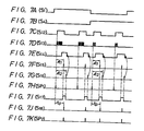
- Figures 4A to 4J are signal waveforms used in explaining the recording operation of the embodiment of Figure 1;
- Figures 5A to 5H are signal waveforms used in explaining the playback operation of the embodiment of Figure 1;
- Figure 6 is a circuit diagram showing an example of a part of the embodiment of Figure 1;
- Figures 7A to 7K are signal waveforms used in explaining the operation of the circuit of Figure 6; and
- Figure 8 is a flow chart used in explaining the generation of a second sampling pulse.
- Figure 1 schematically shows a circuit arrangement of an embodiment of apparatus for recording a digital information signal and according to the present invention, in which only the parts of the circuit that are directly concerned with the present invention and that record and reproduce a tracking pilot signal, a position detecting signal and an erase signal, are shown. In this embodiment, the tracking pilot signal and the erase signal are recorded and reproduced in the normal playback mode, as well as in a variable tape speed playback mode, such as when the tape speed is two or three times the normal tape speed. Thus, the circuit arrangement for recording and reproducing the information signal, such as a PCM signal, for example, is omitted, because they form no part of the present invention.
- Referring to Figure 1,
rotary heads magnetic tape 2, which is used as the recording medium, and therotary heads tape 2 is wrapped around the outside of tape guide drum 3 at its peripheral portion over an angular distance of less than 180°, for example, an angular distance of 90°. Theheads arrow 4H, and thetape 2 is driven in the direction shown by anarrow 4T at a predetermined speed, so that oblique magnetic tracks 5A and 5B are respectively formed on thetape 2 one by one by therotary heads rotary heads - It then follows that there occurs a period in which neither of the two
heads tape 2, and this period corresponds to an angular range of 90 in this embodiment. If this non-contact period is used to perform the addition of redundant data during recording, and to perform error correction and the like during playback, it is possible to simplify the system. - Referring back to Figure 1, a pilot signal oscillator or generator 6 produces a tracking pilot signal P, which has a frequency fo selected to be, for example, about 200 KHz, and is recorded at a relatively high level. If the linearity between tracking phase displacement and a reproduced pilot signal output is ensured, the frequency fo of the tracking pilot signal P is desired to be a frequency presenting a relatively small amount of azimuth loss.
- Position detecting
signal generators tape 2 on which information was previously recorded, that previously recorded information being at the same time erased, it is not necessarily the case that the record tracks are identical in location to the previous corresponding record tracks, so the previously recorded pilot signal must be erased. The frequencies fl and f2 of the position detecting signals S and T are selected to be substantially different from the frequency fo of the pilot signal P, for example, about 700 kHz and 500 kHz, respectively. Also the recording levels thereof are selected to be such as in practice to erase the pilot signal P. - An oscillator or generator 9 generates an erase signal EO. In this case, it is preferable that the erase signal EO is high in erase ratio relative to the signals P, S and T, when the pilot signal P and the position detecting signals S and T are written in an overlapping writing state. The frequency f3 of the erase signal EO is selected to be about 2 MHz.
-
Recording waveform generators recording waveform generator 10, on the basis of the pilot signal P from the pilot signal generator 6, produces the pilot signals which are arranged with a predetermined time interval tp (tp represents the recording time interval of the pilot signal and so on) in accordance with the number of pilot signals P to be recorded per track and the arrangement thereof in the track with a predetermined interval. Therecording waveform generators generators OR gate circuit 14 is provided logically to process the outputs from thegenerators 10 to 13. - A
switching circuit 15 is provided to change over theheads timing signal generator 16. Thetiming signal generator 16 is supplied with a pulse PG with a frequency of 30 Hz, which is indicative of the rotary phase of theheads pulse generator 17 in synchronism with the rotation of amotor 18 that drives theheads timing signal generator 16 derived from the pulse signal PG, is supplied to aphase servo circuit 19 that produces a servo output by which the rotary phase of themotor 18 is controlled. - The signals from the switching
circuit 15, which is changed in position by the switching signal Sl from thetiming signal generator 16, are amplified by anamplifier switching circuit 20A or 20B to thehead tape 2. The switchingcircuits 20A and 20B are connected to the contact R upon recording, whereas they are connectd to the contact P upon playback. - An output signal S2 (Figure 4D) from the
timing signal generator 16 is supplied to adelay circuit 21 in which it is delayed with a delay time corresponding to the interval between theheads pulse generator 17. A delayed output signal S3 (Figure 4E) from thedelay circuit 21 is fed to each ofrecording timing generators 22 to 25. The switching signal Sl from thetiming signal generator 16 is frequency-divided by two by a frequency divider 21' to become a signal S4 (Figure 4C), which then is fed to the recording timing generators 23 to 25. Therecording timing generators 22 to 25 generate timing signals which are used as recording references for the pilot signal and the like. In this case, the trailing edge of the signal S3 (Figure 4E) delayed by thedelay circuit 21 is made coincident with the time at which the first head lA or 1B comes into contact with thetape 2 during one rotation period. - The
recording timing generator 22 produces a pulse signal S5 (Figure 4F) comprising pulses synchronized relative to the trailing edge of the signal S3 during the half rotation periods of onehead head 1B, and pulses delayed by a time T + 3tp/2 (T represents the time corresponding to the half rotation periods of thehead 1B) relative to the trailing edge of the signal S3 during the half rotation periods of theother head 1A. Within each half rotation period there is a predetermined interval Tl between these pulses, and the durations of the pulses are tp. - The recording timing generator 23 generates a pulse signal S6 (Figure 4G) comprising pulses delayed by a time 3tp/2 relative to the trailing edge of the signal S3 only during the half rotation periods of one
head head 1B. There is a predetermined interval Tl between these pulses and, for example, during the odd rotation periods of thehead 1B, the durations of the pulses are tp/2, while during the even rotation periods of thehead 1B, the durations of the pulses are tp/4. - The recording timing generator 24 generates a pulse signal S7 (Figure 4H) delayed relative to the trailing edge of the signal S3 by a time T, only during the half rotation periods of the
other head - The
recording timing generator 25 generates the following signal S8. That is, in the odd rotation periods and during the half rotation period of thehead 1B, there is generated a pair of pulses which are delayed by a time tp relative to the trailing edge of the signal S3 with an interval of time tp/2 therebetween and at a predetermined intereval Tl between pairs of pulses. Each of the pulses has a duration of tp/2. During the other half rotation period of the other head lA, there is generated a pulse signal comprising pulses of duration tp delayed by a time T + tp/2 relative to the trailing edge of the signal S3. There is a predetermined interval Tl between these pulses. On the other hand, in the even rotation periods during the half rotation period of thehead 1B, there is generated a pair of pulses which are delayed by a time tp/2 relative to the trailing edge of the signal S3, whose durations are respectively tp/2 and 3tp/4, and which have an interval tp/4 therebetween, and a predetermined interval Tl between the pulses of each pair of pulses. During the half rotation period of the other head lA, there is generated a pulse signal comprising pulses delayed by a time T + tp/4 relative to the trailing edge of the signal S3. The durations of these pulses are 5tp/4, and they are at a predetermined interval Tl (Figure 41). - The signal S5 (Figure 4F), the signal S6 (Figure 4G), the signal S7 (Figure 4H) and the signal S8 (Figure 41) from the
recording timing generators recording waveform generators generators recording waveform generators OR gate circuit 14 as shown in Figure 1. Thus, they are developed at the output side thereof as a composed signal S9 (Figure 4J). - In Figure 1,
amplifiers heads circuits 20A and 20B are changed in position to their contacts P upon playback. The respective outputs of theamplifiers switching circuit 27. The switchingcircuit 27 is alternately changed in position by a switching signal S'l (Figure 5A) of 30 Hz from thetiming signal generator 16 during the half rotation period including the tape contact period of thehead 1A and during the half rotation period including the tape contact period of thehead 1B similarly to the recording mode, respectively. - A band-
pass filter 28 of a narrow band having a centre pass frequency fo is provided to derive only the pilot signal P from the reproduced output of the switchingcircuit 27. Anenvelope detector 29 is provided to envelope- detect the output from the band-pass filter 28 and the output from theenvelope detector 29 is sampled and then held by a sample-and-hold circuit 30. A comparator ordifferential amplifier 31 is provided to compare the outputs from theenvelope detector 29 and the sample-and-hold circuit 30. A sample-and-hold circuit 32 is provided to sample and hold the compared error signal from thedifferential amplifier 31. The sample-and-hold circuits hold circuit 32 is supplied to anoutput terminal 33 as a tracking control signal. - In order to form the sampling pulse and the like for the sample-and-
hold circuits pass filters circuit 27 which derive only the position detecting signals S and T from the reproduced output. Outputs S10 (Figure 5E) and Sll (Figure 5F) thereof are supplied through a switchingcircuit 36 to acomparator 37 which serves as a waveform shaping circuit. Similarly to the switchingcircuit 27, the switchingcircuit 36 is changed in position by the switching signal S'1 of 30 Hz from thetiming signal generator 16. - Sampling
pulse generators comparator 37. Thesampling pulse generator 38 generates a first sampling pulse SP1 (Figure 5G) in synchronism with the leading edge of the output from thecomparator 37, whereas thesampling pulse generator 39 generates a second sampling pulse SP2 (Figure 5H) with the delay of a predetermined time tp after the first sampling pulse SP1 was produced. These sampling pulses SPl and SP2 are supplied to the sample-and-hold circuits - Next, the circuit operation of Figure 1 will be described with reference to the signal waveforms shown in Figures 4 to 5.
- Upon recording, in response to the pulse PG indicative of the rotary phases of the
heads pulse generator 17, thetiming signal generator 16 produces the signal S2 shown in Figure 4D. The signal S2 is supplied to and delayed by a predetermined time by adelay circuit 21 and so thedelay circuit 21 produces the signal S3 shown in Figure 4E. The signal S3 is supplied to therecording timing generators 22 to 25 so that therecording timing generator 22 produces at its output the signal S5 shown in Figure 4F. The switching signal Sl from thetiming signal generator 16 is supplied to the frequency divider 21' so that the frequency divider 21' produces the signal S4 shown in Figure 4C. The signal S4 is supplied to the recording timing generators 23 to 25 whereby in response to the signals S3 and S4, the recording timing generators 23 to 25 produce the signals S6 to S8 shown in Figures 4G to 41, respectively. - The signals S5, S6, S7 and S8 are respectively supplied to the
recording waveform generators recording waveform generator 10 passes therethrough in synchronism with the signal S5 supplied thereto the pilot signal P from the pilot signal generator 6 at a predetermined interval and for a predetermined time tp as shown in Figure 4F, therecording waveform generator 11 passes therethrough in synchronism with the signal S6 supplied thereto the position detecting signal S from thesynch generator 7 at a predetermined interval and for a predetermined time as shown in Figure 4G, therecording waveform generator 12 passes therethrough in synchronism with the signal S7 supplied thereto the position detecting signal T from thesynch generator 8 at a predetermined interval and for a predetermined time as shown in Figure 4H, and therecording waveform generator 13 passes therethrough in synchronism with the signal S8 supplied thereto the erase signal EO from the synch generator 9 at a predetermined interval and for a predetermined time as shown in Figure 41. - The output signals from the
recording waveform generators 10 to 13 are added together by theOR circuit 14 which then produces the signal S9 shown in Figure 4J. - At this time, let it be considered that for example, the
head 1B records the track 5B1 in Figure 3 (in the first half period tB of Figure 4). Then, the first and second pulses of the signal S5 in Figure 4F correspond to the pilot signals PA1 and PA2, respectively, the first and second pulses of the signal S6 in Figure 4G correspond to the position detecting signals SAl and SA2, respectively, and the first and second pulses formed of a pair of pulses of the signal S8 in Figure 41 correspond to the erase signals EO which are adjacent to the two sides of the position detecting signals SA1 and SA2, respectively. Accordingly, the composed signals of the signals corresponding to the alignments of these signals, namely, PA1, EO, SA1, EO and PA2, EO, SA2 and EO are produced at each group at the output side of theOR circuit 14. - Let it be considered that for example, the
head 1A records the track 5A2 in Figure 3 (in the first half period tA of Figure 4). Then, the first and second pulses of the signal S5 in Figure 4F respectively correspond to the pilot signals PB3 and PB4, the first and second pulses of the signal S7 in Figure 4H respectively correspond to the position detecting signals TB3 and TB4, and the first and second pulses of the signal S8 in Figure 41 respectively correspond to the erase signals EO which are adjacent to the side of the position detecting signals TB3 and TB4. Then, the composed signals of the signals corresponding to the alignments of these signals, namely, TB3, EO, PB3 and PB4, EO and PB4 are produced in each group at the output side of theOR circuit 14. - Further, let it be considered that for example, the
head 1B records the track 5B2 in Figure 3 (the second half period tB of Figure 4). The first and second pulses of the signal S5 in Figure 4F respectively correspond to the pilot signals PA3 and PA4, the first and second pulses of the signal S6 in Figure 4G respectively correspond to the position detecting signals SA3 and SA4, and the first and second pulse formed of a pair of pulses of the signal S8 in Figure 41 respectively correspond to the erase signals EO which are adjacent to the respective sides of the position detecting signals SA3 and SA4. The composed signals of the signals corresponding to the alignment of these signals, namely, PA3, EO, SA3 and EO, and PA4, EO, SA4 and EO are produced at each group at the output side of theOR circuit 14. - Furthermore, let it be considered that for example, the
head 1A records the track 5A3 in Figure 3 (the second half period tA of Figure 4). Then, the first and second pulses of the signal S5 in Figure 4F correspond to the pilot signals PB5 and PB6, respectively, the first and second pulses of the signal S7 in Figure 4H respectively correspond to the position detecting signals TB5 and TB6, and the first and second pulses of the signal S8 in Figure 41 respectively correspond to the erase signals EO which are adjacent to the sides of the position detecting signals TB5 and TB6. The composed signals of the signals corresponding to the alignments of these signals, namely, TB5, EO and PB5 and TB6, EO and PB6 are produced at each group at the output side of theOR circuit 14. - On the other hand, from the
timing signal generator 16, there is produced the switching signal Sl as shown in Figure 4A in response to the pulse PG from thepulse generator 17. The signal Sl is in synchronism with the rotation of theheads head 1A in which the signal Sl is at high level, thehead 1A comes into contact with thetape 2, while during the half rotation period tB in which the signal Sl is at low level, thehead 1B comes into contact with thetape 2. Then, the switchingcircuit 15 is changed in position by the switching signal Sl to the state shown in Figure 1 during the period tA, while it is changed in position to the state opposite to that shown in the figure during the period tB, thus the head lA, 1B is changed over. - Accordingly, when the switching
circuit 15 is in the position opposite to that shown in Figure 1, the signal S9 obtained from theOR circuit 14 is supplied through theamplifier 19B and the contact R of the switching circuit 20B to thehead 1B, whereby at the beginning and the end of the contact period of thehead 1B with thetape 2 within the period tB and in record regions AT1 and AT2 for the tracking signal provided at the two end portions of the track 5B in its longitudinal direction distant from the centre position of the track 5B in its longitudinal direction by anequal length 1, the signal S9 is recorded in the odd rotation period of thehead 1B (the first half period tB of Figure 4) for a time: - tp + tp/2 + tp/2 + tp/2 and a time tp + tp/2 + tp/2 + tp/2,
- while it is recorded thereon in the even rotation period of the
head 1B (the second half period tB of Figure 4), for a time: - tp + tp/2 + tp/4 + tp/2 and a time tp + tp/2 + tp/4 + tp/2, respectively.
- On the other hand, when the switching
circuit 15 is in the state as shown in Figure 1, the signal S9 is supplied through theamplifier 19A and the contact R of theswitching circuit 20A to the head lA, whereby at the beginning and the end of the contact period of thehead 1A with thetape 2 within the period tA and in the similar regions AT1 and AT2 provided in the two end portions of the track 5A in its longitudinal direction distant from the central position of the track 5A in its longitudinal direction by theequal distance 1, the signal S9 is recorded in the odd rotation period (the first half period tA of Figure 4) of thehead 1A for the time: - tp/2 + tp + tp and a time tp/2 + tp + tp,
- while it is recorded in the even rotation period (the second half period tA of Figure 4) of the head lA, for a time:
- tp/4 + 5tp/4 + tp and a time tp/4 + 5tp/4 + tp,
- respectively.
- In other times than those within which these pilot signals, the position detecting signals and the erase signals are recorded, although not shown, an audio PCM signal of one segment portion to be recorded as one track is supplied through the
amplifier 19A to thehead 1A during the period tA, while it is supplied through theamplifier 19B to thehead 1B during the period tB so that they are recorded on the record region Apl other than the record regions of the above-described pilot signals of the respective tracks 5A and 5B. - The reproduction of the signals recorded as described above will now be described.
- Also in this playback mode, the
motor 18 is applied with the phase servo from thephase servo circuit 19 similarly to the recording mode. - The signals reproduced from the
tape 2 by theheads switching circuit 20A and theamplifier 26A and the contact P of the switching circuit 20B and theamplifier 26B to the switchingcircuit 27. The switchingcircuit 27 is alternately changed over by the switching signal S'l of 30 Hz as shown in Figure 5A from the timingsignal generating circuit 16 at the half rotation period tA including the tape contact period of thehead 1A and at the half rotation period tB including the tape contact period of thehead 1B similarly to the recording mode. Accordingly, from the switchingcircuit 27 there is derived an intermittent PCM signal SR of one segment each as shown in Figure 5C. Then, although not shown this PCM signal SR is supplied to a playback processor thereby to be demodulated to the original PCM signal and then further fed to a decoder in which a data of each block is detected by the block synchronizing signal, corrected for error and de-interleaved and then recoverted to the analog audio signal by a digital-to-analog converter and then fed to an output. - The tracking control will be carried out as follows.
- If, now, the
head 1B traces the range of a tracing width W including the track 5B1 as shown by one-dot chain lines in Figure 3, thehead 1B traces also the tracks 5A2 and 5A1 which are adjacent to the track 5B1 so that as shown in Figure 3, in the region ATl, the pilot signal PA1 of the track 5B1, the pilot signal PB3 of the adjacent track 5A2 and the pilot signal PB1 of the adjacent track 5A1 are reproduced by thehead 1B, while in the region AT2, the pilot signal PA2 of the track 5Bl, the pilot signal PB4 of the track 5A2 and the pilot signal PB2 of the adjacent track 5A1 are reproduced by thehead 1B, respectively. At this time, the reproduced output of thehead 1B derived from the switchingcircuit 27 is supplied to the band-pass filter 28 of narrow pass band having the pass centre frequency fo, which passes therethrough only the pilot signals as its output SF as shown in Figure 5D, and this output signal SF is fed to theenvelope detector 29. - The output SR of the switching
circuit 27 is also supplied to the band-pass filters circuit 36 from which the signal S10 is derived when the switching signal S'l is at low level, and the signal Sll when it is at high level, which then are fed to thecomparator 37. - The
comparator 37 compares the signals S10 and Sll supplied thereto with a reference value, waveform-shapes them and supplies them to thesampling pulse generators sampling pulse generator 38 produces the first sampling pulse SP1 in synchronism with the rising edge of the waveform-shaped signal S10 as shown in Figure 5G and the first sampling pulse SPl is supplied to the sample-and-hold circuit 30. At this time, as will be clear from Figure 5, the sampling pulse SP1 makes the sample-and-hold circuit 30 sample the cross-talk components of the pilot signals PB3 and PB4 of the adjacent track 5A2 at the side opposite to the transportion direction of thetape 2 shown by anarrow 4T (Figure 3) and the signal thus sampled is supplied to one input terminal of thedifferential amplifier 31 as the tracking signal of advanced phase. - After the time tp since the sampling pulse SP1 was produced, the cross-talk component of the pilot signals PBI and PB2 of the adjacent track 5A1 at the side of the tape transport direction is supplied to the other input terminals of the
differential amplifier 31 from theenvelope detector 29 at the tracking signals of delayed phase, respectively. Accordingly, thedifferential amplifier 31 compares the tracking signals corresponding to the cross-talk components of the pilot signals PB3 and PB1, and PB4 and PB2, in turn. - Then, the compared error signal from the
differential amplifier 31 is supplied to the sample-and-hold circuit 32 in which it is sampled by the sampling pulse SP2 produced from thesampling pulse generator 39 after the time tp since the sampling pulse SP1 was produced. Consequently, from the sample-and-hold circuit 32, the difference between the two inputs to thedifferential amplifier 31 is produced as the tracking control signal. This tracking control signal is supplied from theoutput terminal 33 to a capstan motor (not shown) which then controls the amount of thetape 2 transported. Thus, thehead 1B is controlled such that the level difference between the two inputs to thedifferential amplifier 31 becomes zero or when thehead 1B traces the track 5B1, thehead 1B traces the two tracks 5A2 and 5A1 at each side of the track 5B1 by the same amount. In other words, thehead 1B is controlled to trace the track 5B1 such that the central position of the width direction of the gap of thehead 1B is made coincident with the centre of the track 5B1. - As to the other tracks, the
heads head 1A traces the track 5A2, there are obtained the cross-talk components of the pilot signals PA3 and PA4, and PA1 and PA2 of the adjacent tracks 5B2 and 5B1. Thus, the cross-talk components of the pilot signals PA3 and PA4 are sampled by the sampling pulse SP1 supplied from thesampling pulse generator 38 to the sample-and-hold circuit 30 thereby to produce the tracking signal. This tracking signal is supplied to thedifferential amplifier 31 at the next stage, and the output corresponding to the cross-talk components of the pilot signals PA1 and PA2 and derived from theenvelope detector 29 is supplied to thedifferential amplifier 31 in which the tracking signals respectively corresponding to the cross-talk components between the pilot signals PA3 and PA1, and PA4 and PA2 are compared with one another. The compared error signal is sampled by the sampling pulse SP2 which is supplied to the sample-and-hold circuit 32 so as to produce the tracking control signal for thehead 1A. - Similarly, when the
head 1B traces the track 5B2, as shown in Figure 3, the cross-talk components of the pilot signals PB5 and PB6 and PB3 and PB4 of the adjacent tracks 5A3 and 5A2 are produced. Thus, the cross-talk components of the pilot signals PB5 and PB6 are sampled by the sampling pulse SP1, the tracking signals corresponding to the cross-talk components of the pilot signals PB5 and PB3, and PB6 and PB4 are compared with one another by thedifferential amplifier 31. Finally, the compared error signal is sampled by the sampling pulse SP2 thereby to produce the tracking control signal for thehead 1B. - Similarly, when the
head 1A traces the track 5A3, as shown in Figure 3, the cross-talk components of the pilot signals PA5 and PA6, and PA3 and PA4 of the two adjacent tracks 5B3 and 5B2 are produced. Thus the cross-talk components of the pilot signals PA5 and PA6 are sampled by the sampling pulse SP1, and the tracking signals corresponding to the cross-talk components of the pilot signals PA5 and PA3, and PA6 and PA4 are controlled by thedifferential amplifier 31. Finally, the compared error signal is sampled by the sampling pulse SP2 thereby to produce the tracking control signal corresponding to the head lA. - Figure 6 shows an example of a practical circuit arrangement of the
sampling pulse generator 39 comprising acounter 40 for counting the pulses of the position detecting signal supplied thereto from thecomparator 37. Adata selector 41 is responsive to the signals S4 and S'l, and then selects the data (set values) of four kinds which are classified by the contents of the position detecting signals; namely, classified by the frequencies and the recording lengths of the position detecting signals S and T in this embodiment. Acoincidence detecting circuit 42 detects whether the count value of thecounter 40 coincides with the data of thedata selector 41. As thecoincidence detecting circuit 42, there is used, for example, a digital comparator. - Delay
circuits 43 to 46 each derive a predetermined delay signal from the sampling pulse SP1. Thecounter 40 is enabled by the output from thedelay circuit 44 and is then cleared by the output from thedelay circuit 45. To an input terminal D of a flip-flop circuit 47, there is supplied the output from thecoincidence detecting circuit 42. To a clock terminal CK of the flip-flop circuit 47, there is supplied the sampling pulse SP1 through thedelay circuit 46, and to a reset terminal R thereof, there is supplied the output of thedelay circuit 45. - To one input terminal of an AND
circuit 48, there is supplied the output of thedelay circuit 43, while to the other input terminal thereof, there is supplied the output developed at an output terminal Q of the flip-flop circuit 47. Then, the sampling pulse SP2 is produced at the output terminal thereof. - The operation of the
sampling pulse generator 39 shown in Figure 6 will be described with reference to the signal waveform diagrams of Figure 7. - When a signal S13 as the position detecting signal, shown in Figure 7D is supplied from the
comparator 37 to thesampling pulse generator 38, thesampling pulse generator 38 produces the sampling pulse SP1 in synchronism with the leading edge of the first pulse of the signal S13 shown in Figure 7H. The sampling pulse SP1 is supplied to the sample-and-hold circuit 30 (Figure 1) and also to thedelay circuits 43 to 46. - The
delay circuit 44 produces at its output side a signal S12 having a duration corresponding substantially to tp/2 in synchronism with the sampling pulse SP1 as shown in Figure 7C. The signal S12 is supplied to thecounter 40 as the enable signal thereof. - The counter 40 counts the pulse of the signal S13 from the
comparator 37 during the period in which the signal S12 is at high level. On the other hand, thedata selector 41 responds to the signals S'l and S4 which are respectively shown in Figures 7A and 7B and selects the data relating to the position detecting signal. If the selected data and the content of thecounter 40 coincide with each other, thecoincidence detecting circuit 42 produces at its output side a signal S14 which continues from the trailing edge of the final pulse of the signal S13 by a predetermined time as shown in Figure 7E. This signal S14 is supplied to the flip-flop circuit 47 as the data thereof. - The
delay circuit 46 produces a signal S15 in synchronism with the sampling pulse SP1 with a delay of a predetermined time 6tl therefrom as shown in Figure 7F. This signal S15 is supplied to the clock terminal CK of the flip-flop circuit 47, in which the signal S14 supplied to the input terminal D thereof is latched. In this case, the delay time 6tl of thedelay circuit 46 is selected to satisfy the condition tp is greater than Δt1 is greater than tp/2. - The
delay circuit 45 produces a signal S16 in synchronism with the sampling pulse SP1 and after therefrom by a predetermined time Δt2 as shown in Figure 7G. This signal S16 is supplied to thecounter 40 thereby to clear the content thereof and is also supplied to the flip-flop circuit 47 thereby to reset it. As a result, the flip-flop circuit 47 produces a signal S17 as shown in Figure 71. In this case, the delay time &t2 of thedelay circuit 45 is selected so as to satisfy the condition Δt2 is greater than tp. - Further, the
delay circuit 43 produces a signal S18 in synchronism relative to the sampling pulse 5P1 a predetermined time tp thereafter as shown in Figure 7J. The signal S18 is supplied to one input terminal of the ANDcircuit 48. Since the ANDcircuit 48 is supplied at the other input terminal thereof with the signal S17 which is formed as described above, the signal S17 is supplied to the ANDcircuit 48 as its gate signal so that in response to the signal S18, the sampling pulse SP2 as shown in Figure 7K is produced. The sampling pulse SP2 is supplied to the sample-and-hold circuit 32. - In this way, the sampling pulse SP2 can be produced.
- The sampling pulse SP2 can be produced by the data processing of a microcomputer (not shown), and this will now be described with reference to the flow chart of Figure 8.
- When the recording apparatus is set in a playback mode at
step 100, the program goes to step 110 in which the position detecting signals S and T are detected. If they are not detected, the detecting operation is repeated atstep 110 until the position detecting signals S and T are detected. If the position detecting signals S and T are detected atstep 110, the first sampling pulse SPl is produced on the basis of the position detecting signals S and T atstep 120 and the pulse Ni of the first sampling pulse SP1 is counted only during the detection periods of the position detecting signals S and T at step 130. - Then, the program goes to the
next step 140 in which it is judged whether the detected position detecting signals S and T are those which are produced first in the playback mode or not. If they are the first ones, the program goes to step 150 in which it is judged whether the interval is the interval tp/2 or not and tp/4 or not. If the interval satisfies either of them, the program goes to step 160 in which the second sampling pulse SP2 is produced. If neither the tp/2 interval nor the tp/4 interval is satisfied atstep 150, they are not the position detecting signals S and T so that the program returns to thestep 110. - If at
step 140 it is judged that the position detecting signals S and T are ones which are produced in the second time after the apparatus was set in the playback mode, the program goes to step 170 in which it is judged whether the polarity of the signal S4 has changed or not. If the polarity of the signal S4 has changed, the program goes to step 180 in which it is judged whether the preceding detection interval is tp/2 or tp/4. If it is tp/2, the program goes further to step 190 in which it is judged whether the interval of the present position detecting signal is tp/4 or not. If it is tp/4, the position detecting signal is the true position detecting signal so that atstep 160, the second sampling pulse SP2 is produced. If on the other hand it is not tp/4, the program returns to step 110. - If it is judged that the preceding detecting interval is tp/4 at
step 180, the program goes to step 200 in which it is judged whether the interval of the present position detecting signal is tp/2 or not. If it is tp/2, it is the true position detecting signal, so that the program returns to step 160 in which the second sampling pulse SP2 is produced. If on the other hand it is not tp/2, the program returns to step 110. - The operations of the
steps 170 to 200 will be described in detail with reference to Figures 5B, 5E and 5F. Atstep 170, if it is judged that the polarity of the signal S4 is changed at the central portion of, for example, Figure 58, the program goes to step 180 in which it is judged whether TB4 of the signal Sll shown in Figure 5F is tp/2 or not and tp/4 or not. Since it is tp/2, the program goes to step 190. Atstep 190, it is judged whether SA3 of the signal S10 shown in Figure 5E is tp/4 or not. Since it is tp/4, the program goes to step 160 in which the second sampling pulse SP2 is produced. Atstep 190, if the signal SA3 is not tp/4, the program returns to step 110. - At
step 180, if TB4 is tp/4, it is judged that it is not the TB4 of the signal Sll but the signal TB6 (accordingly, the time point at which the polarity of the signal S4 is changed is not the central portion of Figure 5B but the right-hand end portion thereof), the program goes to step 200. Atstep 200, it is judged whether SA5 (not shown) of the signal S10 shown in Figure 5E is tp/2 or not. Since it should be tp/2, the second sampling pulse SP2 is produced atstep 160. If atstep 200 it is judged that the signal SA5 is not tp/2, the program returns to step 110. - If at
step 170 the polarity of the signal S4 is not changed, the program goes to step 210 at which it is judged whether the detecting interval is the same as the preceding position detecting signal or not. If it is the same, the program returns to step 160 at which the second sampling pulse SP2 is produced. This will be described with reference to Figure 5E. Since, for example, the first and second pulses SA1 and SA2 of the position detecting signal S10 are the same as tp/2, the second sampling pulse SP2 is produced atstep 160. Then, if, atstep 210, it is judged that the detecting intervals thereof are not equal to each other, such detection is regarded as the mis-detection and hence the first sampling state is maintained and the program returns to step 110. - As described above, by the signal processing of the microcomputer, it becomes possible to produce the second sampling pulse SP2.
- While in the above embodiment the rotary head assembly is a special one in which the tape is wound over an angular distance less than an angular spacing of the heads thereby to carry out the recording and the reproducing, the invention can be applied to a rotary head assembly in which the tape is wrapped over an angular distance the same as the angular spacing of the heads in the ordinary way.
- As set forth above, when the recorded track is traced by a rotary head, a plurality of position detecting signals which are different in frequency in adjacent tracks and different in recording length in the tracks relative to the same frequency are recorded on every predetermined track, the beginning of these position detecting signals are taken as a reference so as to form a pulse signal which detects the pilot signal, and the tracking control of the rotary head is carried out by the tracking control signal based on the detected output. Accordingly, even if the apparatus has a secular mechanical variation, a temperature change or a jitter, without being affected by these parameters, it is possible to carry out the tracking control with good precision even when the apparatus used for playback is different from that used for recording, and also it is possible to achieve compatibility between different apparatus.
- Moreover, since the position detecting signals are different in frequency between the adjacent tracks, it is free of the influence of the cross-talk component and it is possible to widen a range in which the threshold level for detecting the position detecting signal is set.
- Furthermore, since the position detecting signals are different in recording length between the adjacent tracks, the adjacent tracks can be discriminated from each other and it becomes possible to detect the position detecting signals in spite of a track displacement of a wide range.
- In addition, since the position detecting signal for detecting the position of the tracking control pilot signal is recorded so as to begin near the centre of the adjacent pilot signals, it becomes unnecessary to provide a circuit for delaying the position detecting signal so as to place the beginning near the centre of the pilot signal, so the circuit arrangement is simplified.
Claims (10)
Priority Applications (1)
| Application Number | Priority Date | Filing Date | Title |
|---|---|---|---|
| AT85305502T ATE59724T1 (en) | 1984-08-06 | 1985-08-01 | RECORDING OF DIGITAL INFORMATION SIGNALS. |
Applications Claiming Priority (2)
| Application Number | Priority Date | Filing Date | Title |
|---|---|---|---|
| JP164653/84 | 1984-08-06 | ||
| JP59164653A JPH0687330B2 (en) | 1984-08-06 | 1984-08-06 | Digital signal playback device |
Publications (3)
| Publication Number | Publication Date |
|---|---|
| EP0171266A2 true EP0171266A2 (en) | 1986-02-12 |
| EP0171266A3 EP0171266A3 (en) | 1987-05-27 |
| EP0171266B1 EP0171266B1 (en) | 1991-01-02 |
Family
ID=15797264
Family Applications (1)
| Application Number | Title | Priority Date | Filing Date |
|---|---|---|---|
| EP85305502A Expired - Lifetime EP0171266B1 (en) | 1984-08-06 | 1985-08-01 | Recording digital information signals |
Country Status (11)
| Country | Link |
|---|---|
| US (1) | US4739420A (en) |
| EP (1) | EP0171266B1 (en) |
| JP (1) | JPH0687330B2 (en) |
| KR (1) | KR930011692B1 (en) |
| AT (1) | ATE59724T1 (en) |
| AU (1) | AU579171B2 (en) |
| BR (1) | BR8503691A (en) |
| CA (1) | CA1300747C (en) |
| DE (1) | DE3581011D1 (en) |
| DK (1) | DK165569C (en) |
| ES (2) | ES8703702A1 (en) |
Cited By (7)
| Publication number | Priority date | Publication date | Assignee | Title |
|---|---|---|---|---|
| EP0219303A2 (en) * | 1985-10-08 | 1987-04-22 | Sony Corporation | Tracking control apparatus |
| EP0274377A2 (en) * | 1987-01-09 | 1988-07-13 | Deutsche Thomson-Brandt GmbH | Method for transmitting a signal |
| DE3808894A1 (en) * | 1987-03-18 | 1988-09-29 | Victor Company Of Japan | DIGITAL SIGNAL PLAYER WITH ROTATING HEADS |
| DE3809179A1 (en) * | 1987-03-20 | 1988-09-29 | Victor Company Of Japan | METHOD AND DEVICE FOR RECORDING AND PLAYING BACK A DIGITAL SIGNAL USING A ROTATION HEAD |
| WO1988009029A1 (en) * | 1987-05-11 | 1988-11-17 | Exabyte Corporation | Tracking system and method for helical scan recording devices |
| US5008764A (en) * | 1986-09-05 | 1991-04-16 | Victor Company Of Japan, Ltd. | Rotary head type digital signal reproducing apparatus with slow tape speed mode and improved tracking control |
| EP0458531A2 (en) * | 1990-05-21 | 1991-11-27 | Sony Corporation | Tracking error detection |
Families Citing this family (27)
| Publication number | Priority date | Publication date | Assignee | Title |
|---|---|---|---|---|
| JPH07108026B2 (en) * | 1986-06-10 | 1995-11-15 | ソニー株式会社 | Video signal slot reproduction device |
| JPS6318565A (en) * | 1986-07-11 | 1988-01-26 | Pioneer Electronic Corp | Digital signal recording and reproducing device |
| US5003414A (en) * | 1986-07-18 | 1991-03-26 | Pioneer Electronic Corporation | Digital signal reproducing apparatus having improved pilot level compensation control |
| US4839755A (en) * | 1986-09-05 | 1989-06-13 | Victor Company Of Japan, Ltd. | Rotary head type digital signal reproducing apparatus with different modes and tracking control |
| US4875115A (en) * | 1986-09-05 | 1989-10-17 | Pioneer Electronic Corporation | Digital signal tape recording/reproducing apparatus with improved servo control |
| NL8602276A (en) * | 1986-09-10 | 1988-04-05 | Philips Nv | DEVICE FOR WRITING INFORMATION IN A MAGNETIC RECORD CARRIER. |
| JP2537498B2 (en) * | 1986-09-20 | 1996-09-25 | パイオニア株式会社 | Rotating head type digital audio playback device |
| US5182681A (en) * | 1986-12-27 | 1993-01-26 | Yamaha Corporation | Rotating head magnetic recording and reproducing device having automatic tracking control function |
| JPS63276738A (en) * | 1987-01-27 | 1988-11-15 | Yamaha Corp | Magnetic recording and reproducing device |
| US5280399A (en) * | 1988-10-25 | 1994-01-18 | Canon Kabushiki Kaisha | Video signal recording apparatus |
| US4935827A (en) * | 1988-11-09 | 1990-06-19 | Ampex Corporation | Dynamic head position tracking control for a magnetic tape playback system |
| US5065261A (en) * | 1989-11-09 | 1991-11-12 | Exabyte Corporation | Method and apparatus for synchronizing timing signals for helical scan recorder |
| US5068757A (en) * | 1989-11-09 | 1991-11-26 | Exabyte Corporation | Servo tracking for helical scan recorder |
| US5191491A (en) * | 1990-11-09 | 1993-03-02 | Exabyte Corporation | Method and apparatus for reading distorted helical stripes |
| JP2551270B2 (en) * | 1991-08-06 | 1996-11-06 | ソニー株式会社 | Digital signal recorder |
| JP3271103B2 (en) * | 1993-10-08 | 2002-04-02 | ソニー株式会社 | Rotary head type recording / reproducing device |
| JPH09282807A (en) * | 1996-04-13 | 1997-10-31 | Sony Corp | Recording/reproducing apparatus for tape type recording medium and recording/reproducing method |
| US6367047B1 (en) | 1998-10-20 | 2002-04-02 | Ecrix | Multi-level error detection and correction technique for data storage recording device |
| US6381706B1 (en) | 1998-10-20 | 2002-04-30 | Ecrix Corporation | Fine granularity rewrite method and apparatus for data storage device |
| US6307701B1 (en) | 1998-10-20 | 2001-10-23 | Ecrix Corporation | Variable speed recording method and apparatus for a magnetic tape drive |
| US6246551B1 (en) | 1998-10-20 | 2001-06-12 | Ecrix Corporation | Overscan helical scan head for non-tracking tape subsystems reading at up to 1X speed and methods for simulation of same |
| US6421805B1 (en) | 1998-11-16 | 2002-07-16 | Exabyte Corporation | Rogue packet detection and correction method for data storage device |
| US6367048B1 (en) | 1998-11-16 | 2002-04-02 | Mcauliffe Richard | Method and apparatus for logically rejecting previously recorded track residue from magnetic media |
| US6603618B1 (en) | 1998-11-16 | 2003-08-05 | Exabyte Corporation | Method and system for monitoring and adjusting tape position using control data packets |
| US6308298B1 (en) | 1998-11-16 | 2001-10-23 | Ecrix Corporation | Method of reacquiring clock synchronization on a non-tracking helical scan tape device |
| US6624960B1 (en) | 2000-03-10 | 2003-09-23 | Exabyte Corporation | Current sensing drum/cleaning wheel positioning method and apparatus for magnetic storage system |
| US6364234B1 (en) | 2000-03-10 | 2002-04-02 | Michael Donald Langiano | Tape loop/slack prevention method and apparatus for tape drive |
Citations (3)
| Publication number | Priority date | Publication date | Assignee | Title |
|---|---|---|---|---|
| EP0113986A1 (en) * | 1982-12-17 | 1984-07-25 | Sony Corporation | Methods of and apparatus for recording a digital information signal |
| EP0138210A2 (en) * | 1983-10-14 | 1985-04-24 | Hitachi, Ltd. | Rotary head type magnetic recording and reproducing apparatus and method of producing tracking control signals therefor |
| EP0150992A2 (en) * | 1984-01-25 | 1985-08-07 | Sony Corporation | Methods of and apparatus for recording digital signals |
Family Cites Families (6)
| Publication number | Priority date | Publication date | Assignee | Title |
|---|---|---|---|---|
| NL7808639A (en) * | 1978-08-22 | 1980-02-26 | Philips Nv | METHOD FOR POSITIONING DISPLAY ELEMENTS AND APPARATUS FOR PERFORMING THE METHOD |
| JPS5668923A (en) * | 1979-11-09 | 1981-06-09 | Victor Co Of Japan Ltd | Tracking device of magnetic reproducing device |
| JPS5753823A (en) * | 1980-09-17 | 1982-03-31 | Matsushita Electric Ind Co Ltd | Tracking control system |
| US4528605A (en) * | 1982-02-13 | 1985-07-09 | Victor Company Of Japan, Ltd. | Rotary magnetic head scanning control system in a magnetic recording and reproducing apparatus |
| JPS592460A (en) * | 1982-06-28 | 1984-01-09 | Fujitsu Ltd | Data transmission system |
| JPS5936358A (en) * | 1982-08-24 | 1984-02-28 | Matsushita Electric Ind Co Ltd | Tracking system of magnetic recording and reproducing device |
-
1984
- 1984-08-06 JP JP59164653A patent/JPH0687330B2/en not_active Expired - Lifetime
-
1985
- 1985-07-30 CA CA000487769A patent/CA1300747C/en not_active Expired - Lifetime
- 1985-07-31 AU AU45643/85A patent/AU579171B2/en not_active Expired
- 1985-07-31 US US06/761,025 patent/US4739420A/en not_active Expired - Lifetime
- 1985-08-01 AT AT85305502T patent/ATE59724T1/en not_active IP Right Cessation
- 1985-08-01 EP EP85305502A patent/EP0171266B1/en not_active Expired - Lifetime
- 1985-08-01 DE DE8585305502T patent/DE3581011D1/en not_active Expired - Lifetime
- 1985-08-05 BR BR8503691A patent/BR8503691A/en not_active IP Right Cessation
- 1985-08-05 ES ES545893A patent/ES8703702A1/en not_active Expired
- 1985-08-05 DK DK355685A patent/DK165569C/en active
- 1985-08-06 KR KR1019850005652A patent/KR930011692B1/en not_active IP Right Cessation
-
1986
- 1986-11-03 ES ES557184A patent/ES8705734A1/en not_active Expired
Patent Citations (3)
| Publication number | Priority date | Publication date | Assignee | Title |
|---|---|---|---|---|
| EP0113986A1 (en) * | 1982-12-17 | 1984-07-25 | Sony Corporation | Methods of and apparatus for recording a digital information signal |
| EP0138210A2 (en) * | 1983-10-14 | 1985-04-24 | Hitachi, Ltd. | Rotary head type magnetic recording and reproducing apparatus and method of producing tracking control signals therefor |
| EP0150992A2 (en) * | 1984-01-25 | 1985-08-07 | Sony Corporation | Methods of and apparatus for recording digital signals |
Non-Patent Citations (2)
| Title |
|---|
| PATENT ABSTRACTS OF JAPAN, vol. 8, no. 133 (P-281)[1570]; JP - A - 59 036 358 (MATSUSHITA DENKI SANGYO K.K.) 28-02-1984; (Cat. A) * |
| PATENT ABSTRACTS OF JAPAN, vol. 8, no. 208(P-302)[1645], 21th September 1984; JP - A - 59 092460 (SANSUI DENKI K.K.) 28-05-1984; (Cat. A) * |
Cited By (13)
| Publication number | Priority date | Publication date | Assignee | Title |
|---|---|---|---|---|
| EP0219303A3 (en) * | 1985-10-08 | 1988-10-12 | Sony Corporation | Tracking control apparatus |
| EP0219303A2 (en) * | 1985-10-08 | 1987-04-22 | Sony Corporation | Tracking control apparatus |
| US5008764A (en) * | 1986-09-05 | 1991-04-16 | Victor Company Of Japan, Ltd. | Rotary head type digital signal reproducing apparatus with slow tape speed mode and improved tracking control |
| EP0274377A3 (en) * | 1987-01-09 | 1992-05-20 | Deutsche Thomson-Brandt GmbH | Method for transmitting a signal |
| EP0274377A2 (en) * | 1987-01-09 | 1988-07-13 | Deutsche Thomson-Brandt GmbH | Method for transmitting a signal |
| DE3808894A1 (en) * | 1987-03-18 | 1988-09-29 | Victor Company Of Japan | DIGITAL SIGNAL PLAYER WITH ROTATING HEADS |
| DE3809179A1 (en) * | 1987-03-20 | 1988-09-29 | Victor Company Of Japan | METHOD AND DEVICE FOR RECORDING AND PLAYING BACK A DIGITAL SIGNAL USING A ROTATION HEAD |
| DE3809179C2 (en) * | 1987-03-20 | 1999-04-01 | Victor Company Of Japan | Method and device for recording and reproducing a digital signal using a rotary head |
| US4843495A (en) * | 1987-05-11 | 1989-06-27 | Exabyte Corporation | Cyclical servo zone tracking method and apparatus for helical scan recording devices |
| WO1988009029A1 (en) * | 1987-05-11 | 1988-11-17 | Exabyte Corporation | Tracking system and method for helical scan recording devices |
| EP0458531A3 (en) * | 1990-05-21 | 1991-12-11 | Sony Corporation | Tracking error detection |
| EP0458531A2 (en) * | 1990-05-21 | 1991-11-27 | Sony Corporation | Tracking error detection |
| US5233488A (en) * | 1990-05-21 | 1993-08-03 | Sony Corporation | Method and apparatus for detecting tracking errors |
Also Published As
| Publication number | Publication date |
|---|---|
| EP0171266B1 (en) | 1991-01-02 |
| AU579171B2 (en) | 1988-11-17 |
| JPS6142768A (en) | 1986-03-01 |
| ES545893A0 (en) | 1987-02-16 |
| DK165569B (en) | 1992-12-14 |
| BR8503691A (en) | 1986-05-06 |
| DK355685A (en) | 1986-02-07 |
| DK355685D0 (en) | 1985-08-05 |
| EP0171266A3 (en) | 1987-05-27 |
| KR860002080A (en) | 1986-03-26 |
| DE3581011D1 (en) | 1991-02-07 |
| CA1300747C (en) | 1992-05-12 |
| KR930011692B1 (en) | 1993-12-18 |
| ATE59724T1 (en) | 1991-01-15 |
| ES557184A0 (en) | 1987-05-01 |
| JPH0687330B2 (en) | 1994-11-02 |
| DK165569C (en) | 1993-04-26 |
| ES8705734A1 (en) | 1987-05-01 |
| AU4564385A (en) | 1986-02-13 |
| ES8703702A1 (en) | 1987-02-16 |
| US4739420A (en) | 1988-04-19 |
Similar Documents
| Publication | Publication Date | Title |
|---|---|---|
| EP0171266B1 (en) | Recording digital information signals | |
| US4899233A (en) | Apparatus for reproducing a magnetically recorded digital signal using a rotary head with automatic track finding signal extraction and selection for tracking control | |
| EP0117753B1 (en) | Methods of and apparatus for recording digital information signals | |
| US4714971A (en) | Method and apparatus for reproducing signals having improved rotary head tracking control | |
| US4947272A (en) | Signal reproducing device which offsets the tracking error signal for a digital tape player | |
| US4755893A (en) | Tracking control apparatus using pilot signals and position detecting signals of various lengths | |
| US4656539A (en) | Method and apparatus with improved tracking control for recording a digital signal | |
| JPS59142730A (en) | Automatic tracking method | |
| EP0316954B1 (en) | Method of reproducing a tape recorder of the rotary head type | |
| JP2701250B2 (en) | PCM signal recording device | |
| JPS61187186A (en) | Magnetic tape and magnetic recording and reproducing device | |
| EP0357352B1 (en) | Video signal recording/reproducing apparatus | |
| JP2593841B2 (en) | Sync signal detection circuit | |
| JPH0754614B2 (en) | Magnetic recording / reproducing device | |
| JPH04349254A (en) | Recording medium for digital signal | |
| JPH0756715B2 (en) | Tracking controller | |
| JPH0626052B2 (en) | Rotary head type digital signal recording / reproducing device | |
| JPH07107761B2 (en) | Digital signal playback device | |
| JPH04356753A (en) | Digital signal reproducing device | |
| JPH0552578B2 (en) | ||
| JPH0610901B2 (en) | Digital signal playback device | |
| JPS61199289A (en) | Magnetic recording and reproducing device | |
| JPH02306457A (en) | Magnetic tape reproducing device | |
| JPH0466061B2 (en) | ||
| JPS6391858A (en) | Tape running control system |
Legal Events
| Date | Code | Title | Description |
|---|---|---|---|
| PUAI | Public reference made under article 153(3) epc to a published international application that has entered the european phase |
Free format text: ORIGINAL CODE: 0009012 |
|
| AK | Designated contracting states |
Designated state(s): AT BE CH DE FR GB IT LI NL SE |
|
| PUAL | Search report despatched |
Free format text: ORIGINAL CODE: 0009013 |
|
| AK | Designated contracting states |
Kind code of ref document: A3 Designated state(s): AT BE CH DE FR GB IT LI NL SE |
|
| 17P | Request for examination filed |
Effective date: 19870815 |
|
| 17Q | First examination report despatched |
Effective date: 19891117 |
|
| GRAA | (expected) grant |
Free format text: ORIGINAL CODE: 0009210 |
|
| AK | Designated contracting states |
Kind code of ref document: B1 Designated state(s): AT BE CH DE FR GB IT LI NL SE |
|
| REF | Corresponds to: |
Ref document number: 59724 Country of ref document: AT Date of ref document: 19910115 Kind code of ref document: T |
|
| REF | Corresponds to: |
Ref document number: 3581011 Country of ref document: DE Date of ref document: 19910207 |
|
| ET | Fr: translation filed | ||
| ITF | It: translation for a ep patent filed |
Owner name: SOCIETA' ITALIANA BREVETTI S.P.A. |
|
| PLBE | No opposition filed within time limit |
Free format text: ORIGINAL CODE: 0009261 |
|
| STAA | Information on the status of an ep patent application or granted ep patent |
Free format text: STATUS: NO OPPOSITION FILED WITHIN TIME LIMIT |
|
| 26N | No opposition filed | ||
| EAL | Se: european patent in force in sweden |
Ref document number: 85305502.8 |
|
| REG | Reference to a national code |
Ref country code: GB Ref legal event code: IF02 |
|
| PGFP | Annual fee paid to national office [announced via postgrant information from national office to epo] |
Ref country code: GB Payment date: 20040728 Year of fee payment: 20 |
|
| PGFP | Annual fee paid to national office [announced via postgrant information from national office to epo] |
Ref country code: NL Payment date: 20040803 Year of fee payment: 20 |
|
| PGFP | Annual fee paid to national office [announced via postgrant information from national office to epo] |
Ref country code: SE Payment date: 20040806 Year of fee payment: 20 |
|
| PGFP | Annual fee paid to national office [announced via postgrant information from national office to epo] |
Ref country code: FR Payment date: 20040810 Year of fee payment: 20 |
|
| PGFP | Annual fee paid to national office [announced via postgrant information from national office to epo] |
Ref country code: AT Payment date: 20040811 Year of fee payment: 20 |
|
| PGFP | Annual fee paid to national office [announced via postgrant information from national office to epo] |
Ref country code: DE Payment date: 20040812 Year of fee payment: 20 |
|
| PGFP | Annual fee paid to national office [announced via postgrant information from national office to epo] |
Ref country code: CH Payment date: 20040818 Year of fee payment: 20 |
|
| PGFP | Annual fee paid to national office [announced via postgrant information from national office to epo] |
Ref country code: BE Payment date: 20041020 Year of fee payment: 20 |
|
| PG25 | Lapsed in a contracting state [announced via postgrant information from national office to epo] |
Ref country code: GB Free format text: LAPSE BECAUSE OF EXPIRATION OF PROTECTION Effective date: 20050731 |
|
| PG25 | Lapsed in a contracting state [announced via postgrant information from national office to epo] |
Ref country code: NL Free format text: LAPSE BECAUSE OF EXPIRATION OF PROTECTION Effective date: 20050801 |
|
| REG | Reference to a national code |
Ref country code: GB Ref legal event code: PE20 |
|
| BE20 | Be: patent expired |
Owner name: *SONY CORP. Effective date: 20050801 |
|
| REG | Reference to a national code |
Ref country code: CH Ref legal event code: PL |
|
| NLV7 | Nl: ceased due to reaching the maximum lifetime of a patent |
Effective date: 20050801 |
|
| EUG | Se: european patent has lapsed | ||
| BE20 | Be: patent expired |
Owner name: *SONY CORP. Effective date: 20050801 |