DE112010002334B4 - Control method and apparatus for a dual channel weighted LPOS combining scheme - Google Patents
Control method and apparatus for a dual channel weighted LPOS combining scheme Download PDFInfo
- Publication number
- DE112010002334B4 DE112010002334B4 DE112010002334T DE112010002334T DE112010002334B4 DE 112010002334 B4 DE112010002334 B4 DE 112010002334B4 DE 112010002334 T DE112010002334 T DE 112010002334T DE 112010002334 T DE112010002334 T DE 112010002334T DE 112010002334 B4 DE112010002334 B4 DE 112010002334B4
- Authority
- DE
- Germany
- Prior art keywords
- servo
- servo channel
- channel
- fsm
- bit
- Prior art date
- Legal status (The legal status is an assumption and is not a legal conclusion. Google has not performed a legal analysis and makes no representation as to the accuracy of the status listed.)
- Active
Links
Images

Classifications
-
- G—PHYSICS
- G11—INFORMATION STORAGE
- G11B—INFORMATION STORAGE BASED ON RELATIVE MOVEMENT BETWEEN RECORD CARRIER AND TRANSDUCER
- G11B5/00—Recording by magnetisation or demagnetisation of a record carrier; Reproducing by magnetic means; Record carriers therefor
- G11B5/48—Disposition or mounting of heads or head supports relative to record carriers ; arrangements of heads, e.g. for scanning the record carrier to increase the relative speed
- G11B5/58—Disposition or mounting of heads or head supports relative to record carriers ; arrangements of heads, e.g. for scanning the record carrier to increase the relative speed with provision for moving the head for the purpose of maintaining alignment of the head relative to the record carrier during transducing operation, e.g. to compensate for surface irregularities of the latter or for track following
- G11B5/584—Disposition or mounting of heads or head supports relative to record carriers ; arrangements of heads, e.g. for scanning the record carrier to increase the relative speed with provision for moving the head for the purpose of maintaining alignment of the head relative to the record carrier during transducing operation, e.g. to compensate for surface irregularities of the latter or for track following for track following on tapes
-
- G—PHYSICS
- G11—INFORMATION STORAGE
- G11B—INFORMATION STORAGE BASED ON RELATIVE MOVEMENT BETWEEN RECORD CARRIER AND TRANSDUCER
- G11B5/00—Recording by magnetisation or demagnetisation of a record carrier; Reproducing by magnetic means; Record carriers therefor
- G11B5/127—Structure or manufacture of heads, e.g. inductive
- G11B5/29—Structure or manufacture of unitary devices formed of plural heads for more than one track
Abstract
Verfahren zur Überwachung einer Vielzahl von Servokanälen, die in einer Datenspeicherungsvorrichtung (300) angeordnet sind, umfassend: – Bewegen eines sequenziellen Informationsspeicherungsmediums umfassend eine Vielzahl von Servokanälen über einen Lese-/Schreibkopf (160) umfassend eine entsprechende Vielzahl von Servosensoren (140, 150), wobei der besagte Lese-/Schreibkopf (160) in der Datenspeicherungsvorrichtung (300) angeordnet ist, und wobei die Datenspeicherungsvorrichtung (300) einen ersten Servokanal, einen zweiten Servokanal und 0) umfassen, wobei der endliche Automat eine Einzelservokanal-Betriebsart und eine kombinierte Servokanal-Betriebsart umfasst; – Setzen eines Ernn dieser Servokanal einem Servomuster (200) folgt, damit dieser Servokanal als aktiv gekennzeichnet ist; – Setzen eines Bitflags (313/323) durch einen Servokanal, wenn ein neuer LPOS-Bit decodiert wird, wobei besagter Bitflag (313/323) nur gesetzt wird wenn besagter Erfassungsflag (311/321) gesetzt ist; – wirksam wenn zumindest ein Erfassungsflag (311/321) gesetzt ist: Bestimmen, ob ein Bitflag (313/323) durch einen mit dem gesetzten Erfassungsflag...A method for monitoring a plurality of servo channels arranged in a data storage device (300), comprising: - moving a sequential information storage medium comprising a plurality of servo channels over a read / write head (160) comprising a corresponding plurality of servo sensors (140, 150) wherein said read / write head (160) is disposed in the data storage device (300), and wherein the data storage device (300) comprises a first servo channel, a second servo channel and O), the finite state machine having a single servo channel mode and a combined one Servo channel mode includes; - Setting an Ernn of this servo channel follows a servo pattern (200) so that this servo channel is marked as active; - setting a bit flag (313/323) by a servo channel when a new LPOS bit is decoded, said bit flag (313/323) being set only when said detection flag (311/321) is set; - effective if at least one detection flag (311/321) is set: Determining whether a bit flag (313/323) by a detection flag ...
Description
Gebiet der ErfindungField of the invention
Die Erfindung der Anmelderin bezieht sich im Allgemeinen auf ein Verfahren zur Überwachung mehrerer Servokanäle, wo ein Steuerungsschema zwischen einer Einzelservokanal-Betriebsart und einer kombinierten Servokanal-Betriebsart schaltet.Applicant's invention generally relates to a method of monitoring multiple servo channels where a control scheme switches between a single servo channel mode and a combined servo channel mode.
Hintergrund der ErfindungBackground of the invention
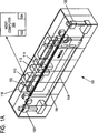
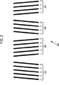
Ein Timing-basierter Servo (TBS) ist eine Technologie, die für lineare Bandlaufwerke entwickelt wurde. In TBS-Systemen bestehen aufgenommene Servomuster aus Übergängen mit zwei verschiedenen azimutalen Steigungen. Laterale Lese-/Schreibkopfpositionen werden von dem relativen Timing detektierter Pulse oder 2-Bit-Einheiten abgeleitet, die durch eine Vielzahl von Servosensoren gemessen werden, die auf dem Lese-Schreibkopf angeordnet sind. TBS-Muster erlauben auch die Codierung zusätzlicher Informationen von longitudinalen Positionen („LPOS”), ohne die Erzeugung der transversalen Positionsfehlersignale („PES”) zu beeinträchtigen. Dies wird dadurch erreicht, dass die Übergänge von ihren nominalen Musterpositionen unter Verwendung von Pulspositionsmodulationen („PPM”) verschoben werden. Eine Spezifikation für das Servoformat in gegenwärtigen Mittelbandlaufwerken wird durch das lineare Tape Open(„LTO”)-Format bereitgestellt. Das komplette Format für LTO-Laufwerke der ersten Generation (LTO-1) wurde durch die European Computer Manufacturers Association („ECMA”) 2001 als ECMA-319 standardisiert.Timing-based servo (TBS) is a technology developed for linear tape drives. In TBS systems, received servo patterns consist of transitions with two different azimuthal slopes. Lateral read / write head positions are derived from the relative timing of detected pulses or 2-bit units measured by a plurality of servo sensors disposed on the read / write head. TBS patterns also allow the encoding of additional information from longitudinal positions ("LPOS") without affecting the generation of transverse position error ("PES") signals. This is achieved by shifting the transitions from their nominal pattern positions using pulse position modulations ("PPM"). A specification for the servo format in current center tape drives is provided by the Linear Tape Open ("LTO") format. The complete format for LTO first generation drives (LTO-1) was standardized by the European Computer Manufacturers Association ("ECMA") in 2001 as ECMA-319.
In Bandlaufwerken sind normalerweise zwei dedizierte Servokanäle verfügbar, von denen LPOS-Informationen und PES abgeleitet werden können. Ein Signal eines Servokanals kann schwächer werden, während das andere Signal des anderen Servokanals nicht detektiert werden kann. In solch einem Fall verliert der durch das Schwächerwerden beeinträchtigte Servokanal das Timing und muss einer Neuerfassung unterzogen werden. Als Konsequenz entstehen zusätzliche Latenzzeiten und der Verlust von Informationen.Tape drives typically have two dedicated servo channels from which LPOS information and PES can be derived. One signal from a servo channel may become weaker while the other signal from the other servo channel can not be detected. In such a case, the servo channel impaired by the fading loses the timing and needs to be re-detected. As a consequence, additional latencies and the loss of information arise.
Zusammenfassung der ErfindungSummary of the invention
Es liegt ein Bedürfnis für ein Verfahren zur Steuerung von einem Servokanal vor, das Betriebsarten kombiniert, die auf dem Status der individuellen Servokanäle und einer Timing-Beziehung (Bitversatz) zwischen den Servosginalen basiert. In einer Ausführungsform wird ein Verfahren zur Überwachung einer Vielzahl von Servosignalen präsentiert, bei dem ein Steuerungsschema zwischen einer Einzelservokanal-Betriebsweise und einer kombinierten Servokanal-Betriebsweise umschaltet. Zunächst hat ein sequenzielles Informationsspeicherungsmedium mehrere Servobänder, die an einem Lese-/Schreibkopf vorbeibewegt werden, mit entsprechenden Servosensoren. Als Nächstes detektiert das Verfahren, ob ein oder mehrere Erfassungsflags gesetzt sind, wobei jeder gesetzte Flag indiziert, dass ein assoziierter Servokanal einem Servomuster folgt. Wenn zumindest ein Erfassungsflag gesetzt ist, detektiert das Verfahren, ob ein Bitflag für den Servokanal gesetzt ist, der mit dem gesetzten Erfassungsflag assoziiert ist, wobei jeder Bitflag die Verfügbarkeit eines neuen LPOS-Bits indiziert. Zuletzt wird eine relative Position für jeden Servosensor in Bezug auf ein assoziiertes Servomuster bestimmt, wenn zumindest ein Bitflag gesetzt ist.There is a need for a method of controlling a servo channel that combines modes based on the status of the individual servo channels and a timing relationship (bit offset) between the servo primes. In one embodiment, a method of monitoring a plurality of servo signals is presented, wherein a control scheme switches between a single servo channel mode and a combined servo channel mode. First, a sequential information storage medium has a plurality of servo tapes passing a read / write head with corresponding servo sensors. Next, the method detects if one or more detection flags are set, with each set flag indicating that an associated servo channel is following a servo pattern. If at least one detection flag is set, the method detects whether a bit flag for the servo channel associated with the set detection flag is set, each bit flag indicating the availability of a new LPOS bit. Lastly, a relative position for each servo-sensor with respect to an associated servo pattern is determined when at least one bit flag is set.
In einer anderen Ausführungsform wird eine Vorrichtung präsentiert, die ein computerlesbares Medium hat, auf dem sich computerlesbarer Programmcode befindet, um mehrere Servosignale zu überwachen, wobei ein Steuerungsschema zwischen einer Einzelservokanal-Betriebsart und einer kombinierten Servokanal-Betriebsart schaltet. Der computerlesbare Programmcode umfasst eine Serie von computerlesbaren Programmschritten, um ein sequenzielles Informationsspeichermedium mit mehreren Servobändern an einem Lese-/Schreibkopf mit entsprechenden Servosensoren vorbeizuführen, um zu detektieren, ob ein oder mehrere Erfassungsflags gesetzt sind, wobei jeder gesetzter Erfassungsflag indiziert, dass ein assoziierter Servokanal einem Servomuster folgt, wenn zumindest ein Erfassungsflag gesetzt ist, um zu detektieren, ob ein Bitflag für den Servokanal gesetzt ist, der mit dem gesetzten Erfassungsflag assoziiert ist, wobei jeder Bitflag indiziert, dass ein neues LPOS-Bit verfügbar ist; und wenn zumindest ein Bitflag gesetzt ist, wird eine relative Position für jeden der Servosensoren in Bezug auf ein assoziiertes Servomuster bestimmt.In another embodiment, a device is presented having a computer readable medium having computer readable program code thereon for monitoring a plurality of servo signals, wherein a control scheme switches between a single servo channel mode and a combined servo channel mode. The computer readable program code comprises a series of computer readable program steps for bypassing a sequential multi-servo information storage medium on a read / write head with corresponding servo sensors to detect if one or more detection flags each set detection flag indicating that an associated servo channel is following a servo pattern when at least one detection flag is set to detect whether a bit flag is set for the servo channel associated with the set detection flag, each bit flag indexing; that a new LPOS bit is available; and if at least one bit flag is set, determining a relative position for each of the servo sensors with respect to an associated servo pattern.
Bei noch einer anderen Ausführungsform wird ein Computerprogrammprodukt präsentiert, das in einem computerlesbaren Medium codiert ist und mit einem programmierbaren Computerprozessor genutzt werden kann, um eine Vielzahl von Servosignalen zu überwachen, wobei ein Steuerungsschema zwischen einer Einzelservokanal-Betriebsart und einer kombinierten Servokanal-Betriebsart schaltet. Das Computerprogrammprodukt umfasst computerlesbaren Programmcode, der den programmierbaren Prozessor zu Folgendem veranlasst: Bewegen eines sequenziellen Informationsspeichermediums mit mehreren Servobändern vorbei an einem Lese-/Schreibkopf mit mehreren entsprechenden Servosensoren, Detektieren, ob ein oder mehrere Erfassungsflags gesetzt sind, wobei jeder gesetzte Erfassungsflag indiziert, dass ein assoziierter Servokanal einem Servomuster folgt, wenn zumindest ein Erfassungsflag gesetzt ist, Detektieren, ob ein Bitflag für den Servokanal gesetzt ist, der mit dem gesetzten Erfassungsflag assoziiert ist, wobei jeder Bitflag die Verfügbarkeit eines neuen LPOS-Bits indiziert; und wenn zumindest ein Bitflag gesetzt ist, Bestimmen einer relativen Position mit Bezug auf ein assoziiertes Servomuster für jeden der Servosensoren.In yet another embodiment, a computer program product encoded in a computer readable medium and usable with a programmable computer processor to monitor a plurality of servo signals is presented, wherein a control scheme switches between a single servo channel mode and a combined servo channel mode. The computer program product includes computer readable program code that causes the programmable processor to: move a sequential multi-servo information storage medium past a read / write head having a plurality of corresponding servo sensors, detecting whether one or more detection flags are set, each set detect flag indicating that an associated servo channel follows a servo pattern when at least one detection flag is set, detecting whether a bit flag for the servo channel associated with the set detection flag is set, each bit flag indicating the availability of a new LPOS bit; and if at least one bit flag is set, determining a relative position with respect to an associated servo pattern for each of the servo sensors.
Bei noch einer weiteren Ausführungsform wird eine Datenspeicherungsvorrichtung mit mehreren Servosensoren und entsprechenden Servosteuerungseinheiten präsentiert.In yet another embodiment, a data storage device having a plurality of servo sensors and corresponding servo control units is presented.
Jede Servosteuerungseinheit umfasst einen Erfassungsflag, der indiziert, dass der Servokanal ein Servomuster erfasst, ein Bitflag, das die Verfügbarkeit eines neuen LPOS-Bits indiziert und einen Servosensor-Positionsindikator („SRPI”), der eine Position eines Servolesers innerhalb eines Servoframes anzeigt.Each servo control unit includes a detection flag indicating that the servo channel detects a servo pattern, a bit flag indicating the availability of a new LPOS bit, and a servo sensor position indicator ("SRPI") indicating a position of a servo-reader within a servo frame.
Bei noch einer anderen Ausführungsform wird eine Datenspeicherungsbibliothek beschrieben, die mehrere Datenspeicherungsvorrichtungen umfasst, wobei jede Datenspeicherungsvorrichtung mehrere Servosensoren und entsprechende Servosteuerungseinheiten hat. Jede Servosteuerungseinheit umfasst einen Erfassungsflag, der indiziert, dass der Servokanal ein Servomuster erfasst hat, ein Bitflag, der die Verfügbarkeit eines neuen LPOS-Bits indiziert, und einen Servosensor-Positionsindikator („SRPI”), der eine Position eines Servolesers innerhalb eines Servoframes anzeigt.In yet another embodiment, a data storage library is described that includes a plurality of data storage devices, each data storage device having a plurality of servo sensors and corresponding servo control units. Each servo control unit includes a detection flag indicating that the servo channel has detected a servo pattern, a bit flag indicating the availability of a new LPOS bit, and a servo sensor position indicator ("SRPI") indicating a position of a servo-reader within a servo frame ,
Kurze Beschreibung der FigurenBrief description of the figures
Die Erfindung wird durch Lesen der folgenden detaillierten Beschreibung in Verbindung mit den Figuren, bei denen gleiche Bezugszeichen für die Bezeichnung gleicher Elemente verwendet werden, besser verstanden, wobei:The invention will be better understood by reading the following detailed description in conjunction with the figures, wherein like numerals are used to designate like elements, and wherein:
Detaillierte Beschreibung bevorzugter AusführungsformenDetailed description of preferred embodiments
Diese Erfindung wird in der folgenden Beschreibung anhand bevorzugter Ausführungsformen mit Bezugnahme auf die Figuren, in denen gleiche Nummern dieselben oder ähnliche Elemente repräsentieren, beschrieben. Innerhalb dieser Spezifikation bedeutet eine Bezugnahme auf „eine Ausführungsform” oder eine ähnliche Sprache, dass ein bestimmtes Merkmal, Struktur oder Charakteristik, die in Verbindung mit der Ausführungsform beschrieben werden, durch zumindest eine Ausführungsform der vorliegenden Erfindung umfasst werden. Daher können in dieser Spezifikation Ausdrücke wie „in einer Ausführungsform” und ähnliche Sprache auf dieselbe Ausführungsform Bezug nehmen, obwohl dies nicht notwendigerweise so sein muss.This invention will be described in the following description with reference to preferred embodiments with reference to the figures in which like numerals represent the same or similar elements. Within this specification, reference to "an embodiment" or similar language means that a particular feature, structure, or characteristic described in connection with the embodiment is encompassed by at least one embodiment of the present invention. Therefore, in this specification, terms such as "in one embodiment" and similar language may be applied to the same Embodiment, although not necessarily so.
Die beschriebenen Merkmale, Strukturen oder Charakteristiken der Erfindung können in irgendeiner passenden Weise in einer oder mehreren Ausführungsformen kombiniert werden. in der folgenden Beschreibung werden zahlreiche spezifische Details erwähnt, um ein ausführliches Verständnis der Ausführungsformen der Erfindung zu ermöglichen. Ein Fachmann wird trotzdem erkennen, dass die Erfindung ohne eines oder mehrere der spezifischen Details oder mit anderen Verfahren, Komponenten, Materialien usw. ausgeführt werden kann. In anderen Fällen werden wohlbekannte Strukturen, Materialien oder Betriebsarten nicht im Detail gezeigt oder beschrieben, um unklare Aspekte der Erfindung zu vermeiden.The described features, structures or characteristics of the invention may be combined in any suitable manner in one or more embodiments. In the following description, numerous specific details are set forth in order to provide a thorough understanding of the embodiments of the invention. However, one skilled in the art will recognize that the invention may be practiced without one or more of the specific details, or with other methods, components, materials, and so forth. In other instances, well-known structures, materials, or modes are not shown or described in detail to avoid obscure aspects of the invention.
In der dargestellten Ausführungsform von
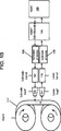
In der dargestellten Ausführungsform von
In
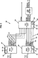
Die vorliegende Erfindung bietet ein Steuerungsschema, um die Verfügbarkeit und den Status der individuellen Servokanäle zu identifizieren, und vereinfacht ein nahtloses Schalten zwischen einer Einzelservokanal-Betriebsart und einer kombinierten Servokanal-Betriebsart, indem die individuellen Servokanäle aktiv oder inaktiv werden. In bestimmten Ausführungsformen überwacht das Steuerungsschema der Anmelderin den Status zweier Servokanäle, um den korrekten Input für das gewichtete Kombinierungsschema zu liefern Das Steuerungsschema der Anmelderin umfasst die in
In
Ferner umfasst die Servosteuerungseinheit
Jede Servosteuerungseinheit kann an die LPOS-Steuereinheit
Der Bitflag
Die Erfassungsflags
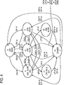
Wenn ein Erfassungsflag für einen oder beide der Servokanäle gesetzt ist, der indiziert, dass der assoziierte Servokanal (die assoziierten Servokanäle) aktiv geworden sind und ein gültiges Servomuster erfasst haben, wird ein Übergang in dem FSM in einen der drei Zwischenzustände 6, 7 oder 10 durchgeführt.If a detection flag is set for one or both of the servo channels indicating that the associated servo channel (s) have become active and detected a valid servo pattern, a transition in the FSM will go to one of the three
Der Zwischenzustand 6 wird angenommen, wenn nur der Erfassungsflag
Der FSM
Wenn der FSM
Wenn beide Servokanäle aktiv sind, bleibt der FSM im Zustand 10 bis einer der beiden Servokanäle ein Bitflag setzt, das die Detektion eines neuen LPOS-Bits indiziert. Wenn beide Servokanäle die Detektion eines neuen LPOS-Bits gleichzeitig indizieren, wird der Kombinierungszustand 14 angenommen und die Information von jedem Servokanal kann durch Verwendung des LPOS-Kombinierungsalgorithmus
Die Zwischenzustände 11 und 12 werden aus dem Zwischenzustand 10 angenommen, wenn ein Bitflag für nur einen der Servokanäle gesetzt wird und wenn beide Servokanäle aktiv sind. Wenn zum Beispiel der FSM
Nach der Detektion des zweiten neuen LPOS-Bits wird der Zwischenzustand 14 angenommen und die Information von jedem Servokanal kann durch den LPOS-Kombinierungsalgorithmus
Wenn der FSM
Nachdem der LPOS-Kombinierungsalgorithmus
In bestimmten Ausführungsformen können individuelle Übergänge, die in Verbindung mit
In anderen Ausführungsformen umfasst die Erfindung Instruktionen, die in irgendeinem anderen Computerprogrammprodukt angeordnet sind, wobei diese durch einen Computer ausgeführt werden, der extern oder intern in Bezug auf das Datenspeicherungssystem ist, um den FSM
Die zuvor in Verbindung mit dem FSM
Zum Beispiel, aber nicht ausschließlich, kann eine typische Zustandssequenz des FSMs, wenn beide Servokanäle aktiv sind und Servokanal 0 vor Servokanal 1 ist, sein:
10 → 11 → 14 → 10 → 11 → 14 → 10 ...For example, but not exclusively, a typical state sequence of the FSM when both servo channels are active and
10 → 11 → 14 → 10 → 11 → 14 → 10 ...
Eine andere typische Zustandssequenz, wenn beide Servokanäle aktiv sind und Servokanal 1 vor Servokanal 0 ist, kann sein:
10 → 12 → 14 → 10 → 12 → 14 → 10 ...Another typical state sequence when both servo channels are active and
10 → 12 → 14 → 10 → 12 → 14 → 10 ...
Wenn Servokanal 0 aktiv ist und Servokanal 1 inaktiv ist, ist eine typische Statussequenz:
6 → 14 → 6 → 14 → 6 ...When
6 → 14 → 6 → 14 → 6 ...
Ein anderes Beispiel einer typischen Statussequenz, bei der beide Servokanäle aktiv sind und neue LPOS-Bitinformationen durch Servokanal 0 indiziert wird, bevor der Servokanal 1 inaktiv wird, ist:
10 → 11 → 14 → 6 → 14 → 6 → 14 → 6 ...Another example of a typical status sequence in which both servo channels are active and new LPOS bit information is indexed by
10 → 11 → 14 → 6 → 14 → 6 → 14 → 6 ...
Der FSM
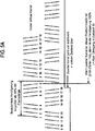
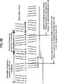
Besonders wenn das Servoformat und die Anordnung des Bandpfades garantieren, dass der Bitversatz unterhalb von fünfzig (50) Prozent der Servoframelänge gehalten wird, wird eine Mehrdeutigkeit der Servokanalabgleichung ohne explizites Wissen des Bitversatzes vermieden. In
Wie in
Ein Übergang vom Zwischenzustand 6 (
Wie mit Bezugnahme auf
In einer Ausführungsform wird ein Zähler für 2-Bit-Einheiten verwendet, um den Bitversatz zwischen den zwei Servokanälen zu bestimmen. Ein Servokanal kann den Zustand von inaktiv zu aktiv nur am Ende eines Servoframes wechseln, das heißt nach der Detektion von achtzehn (18) sequenziellen 2-Bit-Einheiten in Bursts von 4, 4, 5, 5 2-Bit-Einheiten. In bestimmten Ausführungsformen wird der Zustand eines inaktiven Servokanals überprüft, nachdem fünfzig (50) Prozent der Framelänge des aktiven Servokanals detektiert wurden. Diese Position stimmt mit der Detektion der achten 2-Bit-Einheit in einem Servoframe überein oder einem Wert des Zählers für 2-Bit-Einheiten von acht. Wenn an dieser Position der Status des zweiten Servokanals aktiv ist, wie in Bezugnahme auf
Während die bevorzugten Ausführungsformen der vorliegenden Erfindung detailliert dargestellt wurden, sollte es offensichtlich sein, dass Modifikationen und Adaptionen dieser Ausführungsformen durch einen Fachmann durchgeführt werden können, ohne den Umfang der vorliegenden Erfindung, wie sie in den folgenden Ansprüchen beschrieben wird, zu verlassen.While the preferred embodiments of the present invention have been illustrated in detail, it should be apparent that modifications and adaptations of these embodiments may be made by one skilled in the art without departing from the scope of the present invention as described in the following claims.
Claims (14)
Applications Claiming Priority (3)
| Application Number | Priority Date | Filing Date | Title |
|---|---|---|---|
| US12/500,490 | 2009-07-09 | ||
| US12/500,490 US8331055B2 (en) | 2009-07-09 | 2009-07-09 | Control method and apparatus for a dual-channel weighted LPOS combining scheme |
| PCT/EP2010/057678 WO2011003677A1 (en) | 2009-07-09 | 2010-06-02 | Control method and apparatus for a dual-channel weighted lpos combining scheme |
Publications (2)
| Publication Number | Publication Date |
|---|---|
| DE112010002334T5 DE112010002334T5 (en) | 2012-08-02 |
| DE112010002334B4 true DE112010002334B4 (en) | 2012-12-13 |
Family
ID=42342448
Family Applications (1)
| Application Number | Title | Priority Date | Filing Date |
|---|---|---|---|
| DE112010002334T Active DE112010002334B4 (en) | 2009-07-09 | 2010-06-02 | Control method and apparatus for a dual channel weighted LPOS combining scheme |
Country Status (7)
| Country | Link |
|---|---|
| US (1) | US8331055B2 (en) |
| JP (1) | JP5651173B2 (en) |
| CN (1) | CN102473419B (en) |
| CA (1) | CA2765148C (en) |
| DE (1) | DE112010002334B4 (en) |
| GB (1) | GB2484229B (en) |
| WO (1) | WO2011003677A1 (en) |
Families Citing this family (5)
| Publication number | Priority date | Publication date | Assignee | Title |
|---|---|---|---|---|
| US8271857B2 (en) | 2008-05-13 | 2012-09-18 | International Business Machines Corporation | Correcting errors in longitudinal position (LPOS) words |
| US7961424B2 (en) * | 2009-10-30 | 2011-06-14 | International Business Machines Corporation | Multilevel pulse position modulation for efficient encoding of information into servo patterns |
| EP2583999A1 (en) * | 2011-10-20 | 2013-04-24 | Basell Poliolefine Italia S.r.l. | Polyolefin compositions |
| GB2501521A (en) | 2012-04-27 | 2013-10-30 | Ibm | Skew compensation in tape storage device |
| GB2525222A (en) | 2014-04-16 | 2015-10-21 | Ibm | Method and apparatus for operating a tape storage device |
Citations (5)
| Publication number | Priority date | Publication date | Assignee | Title |
|---|---|---|---|---|
| DE69220280T2 (en) * | 1991-04-12 | 1998-01-22 | Sharp Kk | Setup for positioning a magnetic head |
| US6724561B1 (en) * | 2000-06-28 | 2004-04-20 | Storage Technology Corporation | Apparatus and method for compensating for environmental effects on media |
| US20050078398A1 (en) * | 2003-10-10 | 2005-04-14 | International Business Machines Corporation | Apparatus and method to read information from a tape storage medium |
| US20060114596A1 (en) * | 2004-11-30 | 2006-06-01 | International Business Machines Corporation | Tri-state servowriter driver with slow return to zero |
| EP1984919B1 (en) * | 2006-01-26 | 2009-08-05 | International Business Machines Corporation | Synchronous servo channel for longitudinal position detection and position error signal generation in tape drive systems |
Family Cites Families (19)
| Publication number | Priority date | Publication date | Assignee | Title |
|---|---|---|---|---|
| US5448430A (en) * | 1993-08-05 | 1995-09-05 | International Business Machines Corporation | Track following servo demodulation |
| US5909336A (en) * | 1997-02-18 | 1999-06-01 | Texas Instruments Incorporated | Position detection scheme for headerless disk controller |
| US5930065A (en) * | 1997-05-16 | 1999-07-27 | International Business Machines Corporation | Timing based servo longitudinal addressing |
| JP2001250346A (en) * | 2000-03-06 | 2001-09-14 | Fujitsu Ltd | Magnetic tape device |
| US6580581B1 (en) * | 2000-08-16 | 2003-06-17 | International Business Machines Corporation | Recovery of lateral position of a servo system with respect to longitudinal servo bands of a magnetic tape |
| US6791781B2 (en) * | 2001-07-17 | 2004-09-14 | International Business Machines Corporation | Method and apparatus for providing linear position (LPOS) estimations |
| JP3830088B2 (en) * | 2001-11-29 | 2006-10-04 | 富士写真フイルム株式会社 | Servo control method, magnetic tape, and magnetic tape recording / reproducing apparatus |
| US7130140B1 (en) * | 2002-05-06 | 2006-10-31 | Storage Technology Corporation | Polarity encoded pattern for timing based servo |
| US6937413B2 (en) * | 2003-08-08 | 2005-08-30 | International Business Machines Corporation | Tape servo information with superimposed data information providing servo band identification |
| US6992857B2 (en) * | 2004-02-02 | 2006-01-31 | Hewlett-Packard Development Company, L.P. | Weighting servo signals for head positioning |
| US7196859B2 (en) * | 2004-07-09 | 2007-03-27 | Imation Corp. | Processing techniques for time-based servo patterns |
| US7433142B2 (en) * | 2006-02-01 | 2008-10-07 | International Business Machines Corporation | Using at least one servo channel to provide timing recovery and timing information to data channels |
| US7365929B2 (en) * | 2006-07-30 | 2008-04-29 | International Business Machines Corporation | Synchronous servo channel for tape drive systems |
| US7605992B2 (en) * | 2008-01-28 | 2009-10-20 | International Business Machines Corporation | Robust LPOS detection with predictor and bit verifier |
| US7903368B2 (en) * | 2008-02-01 | 2011-03-08 | International Business Machines Corporation | Tape cartridge having tape media with longitudinally shifted servo pattern for increased sampling rate |
| US7990644B2 (en) * | 2008-02-29 | 2011-08-02 | International Business Machines Corporation | Apparatus and method to decode linear position information encoded in a sequential information storage medium |
| US7924520B2 (en) * | 2008-10-01 | 2011-04-12 | Hewlett-Packard Development Company, L.P. | Method and apparatus for determining position of a storage medium |
| US7982988B2 (en) * | 2009-03-09 | 2011-07-19 | International Business Machines Corporation | Combining information from parallel servo channels |
| US7839599B2 (en) * | 2009-03-09 | 2010-11-23 | International Business Machines Corporation | Combining information from parallel servo channels |
-
2009
- 2009-07-09 US US12/500,490 patent/US8331055B2/en not_active Expired - Fee Related
-
2010
- 2010-06-02 CA CA2765148A patent/CA2765148C/en active Active
- 2010-06-02 GB GB1200295.2A patent/GB2484229B/en active Active
- 2010-06-02 JP JP2012518849A patent/JP5651173B2/en active Active
- 2010-06-02 DE DE112010002334T patent/DE112010002334B4/en active Active
- 2010-06-02 CN CN201080030677.XA patent/CN102473419B/en not_active Expired - Fee Related
- 2010-06-02 WO PCT/EP2010/057678 patent/WO2011003677A1/en active Application Filing
Patent Citations (5)
| Publication number | Priority date | Publication date | Assignee | Title |
|---|---|---|---|---|
| DE69220280T2 (en) * | 1991-04-12 | 1998-01-22 | Sharp Kk | Setup for positioning a magnetic head |
| US6724561B1 (en) * | 2000-06-28 | 2004-04-20 | Storage Technology Corporation | Apparatus and method for compensating for environmental effects on media |
| US20050078398A1 (en) * | 2003-10-10 | 2005-04-14 | International Business Machines Corporation | Apparatus and method to read information from a tape storage medium |
| US20060114596A1 (en) * | 2004-11-30 | 2006-06-01 | International Business Machines Corporation | Tri-state servowriter driver with slow return to zero |
| EP1984919B1 (en) * | 2006-01-26 | 2009-08-05 | International Business Machines Corporation | Synchronous servo channel for longitudinal position detection and position error signal generation in tape drive systems |
Also Published As
| Publication number | Publication date |
|---|---|
| JP2012532401A (en) | 2012-12-13 |
| DE112010002334T5 (en) | 2012-08-02 |
| GB2484229B (en) | 2016-09-07 |
| CA2765148A1 (en) | 2011-01-13 |
| WO2011003677A1 (en) | 2011-01-13 |
| JP5651173B2 (en) | 2015-01-07 |
| GB201200295D0 (en) | 2012-02-22 |
| CA2765148C (en) | 2017-09-19 |
| CN102473419B (en) | 2015-07-22 |
| GB2484229A (en) | 2012-04-04 |
| US8331055B2 (en) | 2012-12-11 |
| CN102473419A (en) | 2012-05-23 |
| US20110007413A1 (en) | 2011-01-13 |
Similar Documents
| Publication | Publication Date | Title |
|---|---|---|
| DE60305155T2 (en) | CONTINUOUS SERVO SIGNAL WITH FIXED DISTANCE BETWEEN TRANSACTIONS | |
| DE60105437T2 (en) | METHOD AND DEVICE FOR REGENERATING A SIDE POSITION OF A SERVO SYSTEM IN RELATION TO THE LONG-SIDED SERVOSPURS OF A MAGNETIC STRIP | |
| DE2921387C2 (en) | Method for exchanging information between a data processing system and a magnetic disk storage device | |
| DE112010002334B4 (en) | Control method and apparatus for a dual channel weighted LPOS combining scheme | |
| DE112011100154T5 (en) | Method of using variable time intervals in a servo band | |
| DE69727914T2 (en) | Servo system for tracking magnetic tracks with identification pulse widths | |
| DE2307672C2 (en) | Arrangement for error correction when recording and reading data signals of a multi-track data recording | |
| DE112018004627T5 (en) | CONFIGURATIONS OF HYBRID SERVO PATTERN FOR MAGNETIC TAPE | |
| DE2732515A1 (en) | DATA SIGNAL RECORDING DEVICE | |
| EP0023565A1 (en) | Arrangement for track-dependent position control in a system for recording and/or reproducing information on a magnetic recording disc, particularly of the flexible type and a magnetic recording disc therefor | |
| DE112011100150T5 (en) | Positioning of a coarse actuator of a belt servo system with a composite actuator at the maximum maximum value of lateral belt movement | |
| DE3713397A1 (en) | METHOD AND DEVICE FOR RECORDING AND PLAYING BACK DATA ON STORAGE DISKS | |
| DE112020004007B4 (en) | FIXING READ ERRORS IN A TAPE DRIVE | |
| DE1774307C3 (en) | Circuit arrangement for finding and eliminating faults in recordings | |
| DE69918770T2 (en) | Servo system and method with multi-phase clock signal | |
| DE112012004436B4 (en) | Servo write assembly | |
| DE69920868T2 (en) | PURGE SERVOSIGNAL PATTERN WRITING METHOD FOR MAGNETIC PLATE DEVICE | |
| DE2056011C3 (en) | Write control device in a magnetic tape unit | |
| WO1985003797A1 (en) | Method for controlling a video-tape apparatus for the automatic spotting of recorded video-tape segments and video-tape apparatus for implementing such method | |
| DE2723485A1 (en) | CIRCUIT FOR THE DETAILED DISCRIMINATION DURING READING OF DATA PREVIOUSLY RECORDED IN VARIOUS CODES | |
| DE2328025C3 (en) | Method for magnetic recording of digital information in a magnetic disk storage | |
| DE3011810A1 (en) | METHOD AND DEVICE FOR FINDING A STORAGE SPACE ON A RECORDING CARRIER | |
| DE1449425B2 (en) | Device for determining errors in a magnetic tape | |
| DE2237944B2 (en) | Circuit arrangement for the control and status display of peripheral units | |
| DE2052317A1 (en) | Device and method for recording binary information |
Legal Events
| Date | Code | Title | Description |
|---|---|---|---|
| R012 | Request for examination validly filed | ||
| R016 | Response to examination communication | ||
| R016 | Response to examination communication | ||
| R016 | Response to examination communication | ||
| R018 | Grant decision by examination section/examining division | ||
| R020 | Patent grant now final |
Effective date: 20130314 |
|
| R084 | Declaration of willingness to licence |