
Hello Engineers. In this tutorial, I am going to discuss an Audio VU meter Circuit. What is a VU meter circuit? A VU meter is also an audio Visualizer that has a group of LEDs as dot or Bar display. VU meters are basically used with the Amplifiers and audio systems to analyze and display the audio spectrum. The LED dot or bar display lights up LEDs-high to low showing the level of the pitch with matching the pattern of bass going high or low. Here in this article, I am going to discuss a VU meter Circuit using the LM3915 IC.
A VU meter Circuit can also be called an Audio Visualizer or Visual Audio spectrum Analyzer.
IC LM3915 and short Datasheet
IC LM3915 is an 18pin monolithic Integrated Circuit that senses the analog signal voltage levels and accordingly drives 10 LEDs Bar or dot Matrix display.
The IC allows us to set or program the reference voltage and LED current through the pins: RefL, RefH, RefH, RefAdj based on the load type, by selecting appropriate resistors value.
This IC provides a Logarithmic 3dB/ step analog display. This in total is 30db which one IC can handle. Of course, it’s expandable up to 90db if cascading 3 IC together.
You can change the operation mode from bar display to Dot LED display once the pin 9 (Mode) goes high. Supply voltage. Input buffer accepts signals down to the ground and up to within 1.5V of the positive supply.
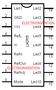
LM3915 PINOUTS and PIN Description
| PIN 1 and 10 to 18 | LED1, LED2, LED3 to LED10 | Pins to control 10 LEDs. |
| PIN 2 | V- / Ground | This is the ground pin of the IC connected to the ground. |
| PIN 3 | V+ / Vcc | Supply Voltage 3V to 25v |
| PIN 4 | RLO | Low-level voltage for potential divider |
| PIN 5 | Signal | Analog signal Input pin based on which the LEDs are is controlled. |
| PIN 6 | RHI | High-Level voltage for potential divider |
| PIN 7 | REF OUT | Output Reference Voltage for LED current limiting |
| PIN 8 | REF ADJ | This adjusts pin for voltage reference |
| PIN 9 | Mode | When this goes high or low, Select between Dot/Bar Mode |
Materials
- LM3915 IC- 1Pc
- D1-D10- LEDs ( any color)
- C1- 22uf, 25V- 1pc
- R1,R2-1K
- Switch( small SPST)
- Battery 5V DC (Or 5v DC source)
- 18 PIN DIP connector
- PCB
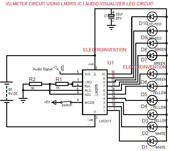
LM3915 VU meter circuit | Audio spectrum Visualizer
How does this VU meter circuit works?
We have already discussed a bit about the IC LM3915 which is a monolithic LEDs Display controller.
The IC is where the main controller and given the 5v DC supply input. We can operate it in any range between 3 to 25V. We have only used a capacitor, LEDs, switch, and two resistors as an additional component to use this IC. The IC can operate between 3V to 35V. The Power input at the Vcc pin is just to drive the IC and its operation.
INPUT SIGNAL: the input signal [At pin 5 SIG] can be in the form of audio or music signal, varying light intensity, or Pulse sort of signal.
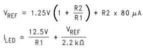
The Audio signal can have a vary range from 1.2 to 12V. Based on this voltage, the reference voltage has to be set in the circuit using the resistors R1 and R2 in the circuit.
For, example, our audio signal’s amplitude is 3.2V. So, the pin RHI and REF OUT should be supplied with 3.2V, and the pin RLO should be supplied with 0V. In case we have used 1K and 1K so it’s 3.6.
Check below formula in fig:3
Moreover, we can also set the output current that should flow through the LEDs (i.e I Led) by using a resistor divider network on pin 7 (Ref Out). All we can do is by selecting appropriate R1 and R2. Below formulae are used fig3:
The IC has 2 operating modes, one is the BAR graph LEDs display and the other is DOT Display. Makin PIN 9 low and high will eventually help you change the mode.
There is a switch used in the circuit. I suggest just keep PIN 9 high so as to get a perfect Audio spectrum Visualizer experience.
So, this is how this IC does this job with just a few passive components help. The circit is very simple and easy, yet effective. I hope you like it.
Comment below if you liked it or have something to ask.
thanks for explaining working of this ic