
Having two or more Arduinos able to communicate with each other wirelessly opens up a world of possibilities, such as remotely monitoring sensor data, controlling robots, home automation, and so on.
In this tutorial, we’ll teach you step-by-step how to make two Arduino boards communicate wirelessly using HC-05 Bluetooth modules.
Overview
To make two Arduino boards communicate wirelessly, we need to configure one HC-05 module as master and the other as slave, and pair them. This is known as master-slave setup—It’s the simplest way to establish a wireless connection between two devices. The master device initiates the connection and searches for other devices, while the slave device waits for the connection request from the master device. Once the connection is established, the master and slave devices can exchange data bidirectionally.
In order to configure the HC-05 modules, we need to connect them to a PC and use a serial terminal software (such as Arduino IDE Serial Monitor or PuTTY) to send AT commands.
Step 1: Connecting HC-05 Module to the PC
Let’s first connect the HC-05 module to the PC. You can either use a USB-to-TTL converter or use an Arduino as a medium between the PC and the HC-05 module.
Connecting the HC-05 Module to the Arduino is as easy as applying power and wiring up the serial Rx and Tx pins. The TXD of the HC-05 module is connected to the Arduino’s D1, the RXD to D0, GND to GND, and VCC to 5V.
Note that the Rx pin on the HC-05 module is not 5V-tolerant. So, if you are using a 5V microcontroller such as an Arduino UNO, you need to step down the Tx signal from the Arduino to 3.3V using a resistor divider. A 1K resistor between HC-05’s Rx and Arduino’s D0, and a 2K resistor between HC-05’s Rx and GND, will work just fine.
To summarize, the following are the connections:
| HC-05 Module | Arduino | Notes | |
| VCC | 5V | – | |
| GND | GND | – | |
| TX | D1 | – | |
| RX | D0 | Use level shifter if using 5V MCU |
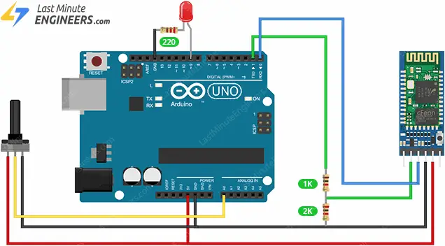
The image below shows how to connect the HC-05 module to the Arduino Uno.

If you use this method, make sure that an empty sketch is uploaded to the Arduino.
Step 2: Configuring the HC-05 Modules
Let’s configure one HC-05 module as a master and the other as a slave.
Slave Configuration
- Press and hold the button on the first HC-05 module while powering it up. This will put the module in AT mode, which means it is ready to receive AT commands. You should see the onboard LED blinking at a slow and steady rate.
- When you connect the HC-05 to your PC, it will be recognized as a COM port. Opening up your device manager, and looking in the “Ports (COM & LPT)” tree, you’ll find a new port. In the Arduino IDE, navigate to Tools > Port and choose that COM port.
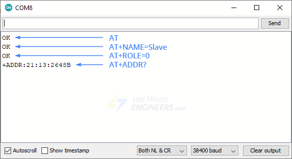
- Open up the Serial Monitor via Tools > Serial Monitor, and make sure that the baud rate in the lower right-hand corner is set to 38400 and the ‘Both NL and CR‘ option is selected. This means when you send commands to the HC-05, it will put a newline and return at the end.
- Now type “AT” (without quotes) in the textbox at the top of the Serial Monitor and click the Send button. You should see “OK” as a response from the module. This means the communication is successful.
- Type “AT+NAME=Slave” and press enter. This will change the name of the module to “Slave”. You should see “OK” as a response.
- Type “AT+ROLE=0” and press enter. This will set the role of the module to slave. You should see “OK” as a response. Upon setting the role, the HC-05 might restart and exit AT mode; if this happens, please put it back into AT mode.
- Type “AT+ADDR?” and press enter. This will display the address of the module in hexadecimal format, such as “1234:56:abcdef“. Note down this address, as you will need it when configuring the master device.
- Disconnect the HC-05 module.
Master Configuration
- Press and hold the button on the second HC-05 module while powering it up. This will put the module in AT mode, which means it is ready to receive AT commands. You should see the onboard LED blinking at a slow and steady rate.
- When you connect the HC-05 to your PC, it will be recognized as a COM port. Opening up your device manager, and looking in the “Ports (COM & LPT)” tree, you’ll find a new port. In the Arduino IDE, navigate to Tools > Port and choose that COM port.
- Open up the Serial Monitor via Tools > Serial Monitor, and make sure that the baud rate in the lower right-hand corner is set to 38400 and the ‘Both NL and CR‘ option is selected. This means when you send commands to the HC-05, it will put a newline and return at the end.
- Type “AT” (without quotes) and press enter. You should see “OK” as a response from the module. This means the communication is successful.
- Type “AT+NAME=Master” and press enter. This will change the name of the module to “Master”. You should see “OK” as a response.
- Type “AT+ROLE=1” and press enter. This will set the role of the module to master. You should see “OK” as a response. Upon setting the role, the HC-05 might restart and exit AT mode; if this happens, please put it back into AT mode.
- Type “AT+CMODE=0” and press enter. This will set the connection mode of the module to a fixed address. You should see “OK” as a response.
- Type “AT+BIND=1234,56,abcdef” and press enter. Replace the address with the one you noted down from the slave module. It is important to note that when writing the address, you must use commas rather than colons. This will pair our master module to our slave module. You should see “OK” as a response.
- Disconnect the HC-05 module.

Please keep in mind that you can enter “1” instead of “0” in the “AT+CMODE” command. This option allows the master to connect to any device within its transmission range, rather than being restricted to a specific slave device. If you choose this option, you can skip the second-to-last step; however, be aware that this results in a less secure configuration.
That’s it; your HC-05 modules are now configured as master and slave devices. Now, when you power up the modules again, it will take just a matter of seconds for the master to establish a connection with the slave. You’ll notice the LED flash pattern on both modules changes to two quick flashes followed by a pause, indicating a successful connection.
Step 3: Connecting the Hardware
So, we’re now ready to make a practical example for this tutorial.
Our example is going to be very simple, but it will demonstrate how communication between two Arduino boards can be achieved. We are simply going to use a potentiometer on the master side to control the servo motor on the slave side, and a push button on the slave side to control an LED on the master side.
Master Arduino Connections:
Connect the HC-05 Bluetooth module’s VCC to Arduino’s 5V, GND to GND, TXD to Arduino’s RX (Digital Pin 0), and RXD through a voltage divider to Arduino’s TX (Digital Pin 1). Attach one outer pin of the potentiometer to 5V, the opposite outer pin to GND, and its middle pin (wiper) to A0. For the LED, link its positive (longer leg) via a 220Ω resistor to digital pin D9 and its negative (shorter leg) to GND.
Slave Arduino Connections:
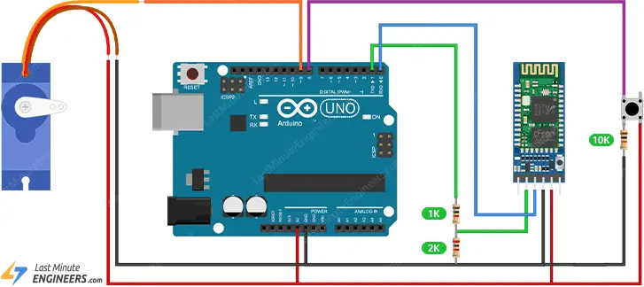
For the HC-05 Bluetooth module on the slave side, connect VCC to Arduino’s 5V, GND to GND, TXD to Arduino’s RX (Digital Pin 0), and RXD through a voltage divider to TX (Digital Pin 1). For the servo motor, connect its Power (Red) wire to 5V, Ground (Brown/Black) wire to GND, and Signal (Yellow/Orange) wire to a PWM digital pin, D9. Connect one leg of the push button to digital pin D8. Connect that same leg of the button to ground through a 10K pull-down resistor. Connect the other leg of the button to the 5V.
Step 4: Uploading the Code
We have two Arduino sketches to upload to the Arduino boards.
Master Code
Upload the following sketch to the Master Arduino:
#define ledPin 9

int state = 0;
int potValue = 0;

void setup() {
  pinMode(ledPin, OUTPUT);
  digitalWrite(ledPin, LOW);
  Serial.begin(38400); // Default communication rate of the Bluetooth module
}

void loop() {
 if(Serial.available() > 0){ // Checks whether data is comming from the serial port
    state = Serial.read(); // Reads the data from the serial port
 }
 // Controlling the LED
 if (state == '1') {
  digitalWrite(ledPin, HIGH); // LED ON
  state = 0;
 }
 else if (state == '0') {
  digitalWrite(ledPin, LOW); // LED ON
  state = 0;
 }
 // Reading the potentiometer
 potValue = analogRead(A0);
 int potValueMapped = map(potValue, 0, 1023, 0, 255);
 Serial.write(potValueMapped); // Sends potValue to servo motor
 delay(10);
}
Slave Code
Upload the following sketch to the Slave Arduino:
#include <Servo.h>
#define button 8

Servo myServo;
int state = 20;
int buttonState = 0;

void setup() {
  pinMode(button, INPUT);
  myServo.attach(9);
  Serial.begin(38400); // Default communication rate of the Bluetooth module
}

void loop() {
 if(Serial.available() > 0){ // Checks whether data is comming from the serial port
    state = Serial.read(); // Reads the data from the serial port
 }
 // Controlling the servo motor
 myServo.write(state);
 delay(10);

 // Reading the button
 buttonState = digitalRead(button);
 if (buttonState == HIGH) {
   Serial.write('1'); // Sends '1' to the master to turn on LED
 }
 else {
   Serial.write('0');
 }
}
Code Explanation:
In the master Arduino sketch, digital pin 9 is set up to control an LED, and the potentiometer is connected to analog pin A0. Once initialized, the code checks for incoming serial data, which represents the button state from the slave. Depending on the received value (‘1’ or ‘0’), the LED is turned on or off, respectively. Simultaneously, the potentiometer value is read, mapped from its range (0-1023) to a byte value (0-255), and this mapped value is sent via Bluetooth to control the servo motor on the slave side.
For the slave Arduino, the code starts by including the Servo library and defining digital pin 8 for button input. A servo object is initiated and connected to digital pin 9. In the loop, the code constantly checks for incoming serial data. This data directly determines the servo motor’s angle. Simultaneously, the button’s state is monitored. If pressed, a ‘1’ is sent to the master to illuminate the LED; otherwise, a ‘0’ is sent.
Step 5: Testing it Out
Now rotate the potentiometer on the master Arduino. As you adjust its position, the servo motor on the slave Arduino should move in response. The rotation of the potentiometer determines the angle of the servo.
Now press the button on the slave Arduino. When pressed, the LED on the master Arduino should illuminate. Releasing the button should turn the LED off.
