WO2014171380A1 - Muffler cutter - Google Patents
Muffler cutter Download PDFInfo
- Publication number
- WO2014171380A1 WO2014171380A1 PCT/JP2014/060314 JP2014060314W WO2014171380A1 WO 2014171380 A1 WO2014171380 A1 WO 2014171380A1 JP 2014060314 W JP2014060314 W JP 2014060314W WO 2014171380 A1 WO2014171380 A1 WO 2014171380A1
- Authority
- WO
- WIPO (PCT)
- Prior art keywords
- exhaust pipe
- sound
- heat shield
- muffler cutter
- insulating material
- Prior art date
Links
Images


Classifications
-
- F—MECHANICAL ENGINEERING; LIGHTING; HEATING; WEAPONS; BLASTING
- F01—MACHINES OR ENGINES IN GENERAL; ENGINE PLANTS IN GENERAL; STEAM ENGINES
- F01N—GAS-FLOW SILENCERS OR EXHAUST APPARATUS FOR MACHINES OR ENGINES IN GENERAL; GAS-FLOW SILENCERS OR EXHAUST APPARATUS FOR INTERNAL COMBUSTION ENGINES
- F01N13/00—Exhaust or silencing apparatus characterised by constructional features ; Exhaust or silencing apparatus, or parts thereof, having pertinent characteristics not provided for in, or of interest apart from, groups F01N1/00 - F01N5/00, F01N9/00, F01N11/00
- F01N13/14—Exhaust or silencing apparatus characterised by constructional features ; Exhaust or silencing apparatus, or parts thereof, having pertinent characteristics not provided for in, or of interest apart from, groups F01N1/00 - F01N5/00, F01N9/00, F01N11/00 having thermal insulation
-
- F—MECHANICAL ENGINEERING; LIGHTING; HEATING; WEAPONS; BLASTING
- F01—MACHINES OR ENGINES IN GENERAL; ENGINE PLANTS IN GENERAL; STEAM ENGINES
- F01N—GAS-FLOW SILENCERS OR EXHAUST APPARATUS FOR MACHINES OR ENGINES IN GENERAL; GAS-FLOW SILENCERS OR EXHAUST APPARATUS FOR INTERNAL COMBUSTION ENGINES
- F01N1/00—Silencing apparatus characterised by method of silencing
- F01N1/24—Silencing apparatus characterised by method of silencing by using sound-absorbing materials
-
- F—MECHANICAL ENGINEERING; LIGHTING; HEATING; WEAPONS; BLASTING
- F01—MACHINES OR ENGINES IN GENERAL; ENGINE PLANTS IN GENERAL; STEAM ENGINES
- F01N—GAS-FLOW SILENCERS OR EXHAUST APPARATUS FOR MACHINES OR ENGINES IN GENERAL; GAS-FLOW SILENCERS OR EXHAUST APPARATUS FOR INTERNAL COMBUSTION ENGINES
- F01N1/00—Silencing apparatus characterised by method of silencing
- F01N1/003—Silencing apparatus characterised by method of silencing by using dead chambers communicating with gas flow passages
- F01N1/006—Silencing apparatus characterised by method of silencing by using dead chambers communicating with gas flow passages comprising at least one perforated tube extending from inlet to outlet of the silencer
-
- F—MECHANICAL ENGINEERING; LIGHTING; HEATING; WEAPONS; BLASTING
- F01—MACHINES OR ENGINES IN GENERAL; ENGINE PLANTS IN GENERAL; STEAM ENGINES
- F01N—GAS-FLOW SILENCERS OR EXHAUST APPARATUS FOR MACHINES OR ENGINES IN GENERAL; GAS-FLOW SILENCERS OR EXHAUST APPARATUS FOR INTERNAL COMBUSTION ENGINES
- F01N1/00—Silencing apparatus characterised by method of silencing
- F01N1/02—Silencing apparatus characterised by method of silencing by using resonance
- F01N1/04—Silencing apparatus characterised by method of silencing by using resonance having sound-absorbing materials in resonance chambers
-
- F—MECHANICAL ENGINEERING; LIGHTING; HEATING; WEAPONS; BLASTING
- F01—MACHINES OR ENGINES IN GENERAL; ENGINE PLANTS IN GENERAL; STEAM ENGINES
- F01N—GAS-FLOW SILENCERS OR EXHAUST APPARATUS FOR MACHINES OR ENGINES IN GENERAL; GAS-FLOW SILENCERS OR EXHAUST APPARATUS FOR INTERNAL COMBUSTION ENGINES
- F01N13/00—Exhaust or silencing apparatus characterised by constructional features ; Exhaust or silencing apparatus, or parts thereof, having pertinent characteristics not provided for in, or of interest apart from, groups F01N1/00 - F01N5/00, F01N9/00, F01N11/00
- F01N13/08—Other arrangements or adaptations of exhaust conduits
- F01N13/082—Other arrangements or adaptations of exhaust conduits of tailpipe, e.g. with means for mixing air with exhaust for exhaust cooling, dilution or evacuation
-
- F—MECHANICAL ENGINEERING; LIGHTING; HEATING; WEAPONS; BLASTING
- F01—MACHINES OR ENGINES IN GENERAL; ENGINE PLANTS IN GENERAL; STEAM ENGINES
- F01N—GAS-FLOW SILENCERS OR EXHAUST APPARATUS FOR MACHINES OR ENGINES IN GENERAL; GAS-FLOW SILENCERS OR EXHAUST APPARATUS FOR INTERNAL COMBUSTION ENGINES
- F01N13/00—Exhaust or silencing apparatus characterised by constructional features ; Exhaust or silencing apparatus, or parts thereof, having pertinent characteristics not provided for in, or of interest apart from, groups F01N1/00 - F01N5/00, F01N9/00, F01N11/00
- F01N13/20—Exhaust or silencing apparatus characterised by constructional features ; Exhaust or silencing apparatus, or parts thereof, having pertinent characteristics not provided for in, or of interest apart from, groups F01N1/00 - F01N5/00, F01N9/00, F01N11/00 having flared outlets, e.g. of fish-tail shape
-
- F—MECHANICAL ENGINEERING; LIGHTING; HEATING; WEAPONS; BLASTING
- F01—MACHINES OR ENGINES IN GENERAL; ENGINE PLANTS IN GENERAL; STEAM ENGINES
- F01N—GAS-FLOW SILENCERS OR EXHAUST APPARATUS FOR MACHINES OR ENGINES IN GENERAL; GAS-FLOW SILENCERS OR EXHAUST APPARATUS FOR INTERNAL COMBUSTION ENGINES
- F01N2470/00—Structure or shape of gas passages, pipes or tubes
- F01N2470/02—Tubes being perforated
Definitions
- the present invention relates to a muffler cutter.
- Combustion gas (exhaust gas) discharged from the car engine is finally connected to the engine through exhaust manifold, exhaust manifold direct catalytic converter, front tube, underfloor catalytic converter, center muffler, main muffler, etc. It is discharged to the outside from the end (tail end) of the tail pipe (see, for example, Patent Document 1 (Japanese Patent Laid-Open No. 2008-190371)).
- a muffler cutter is generally attached to the end of the tail pipe, and the aesthetics and luxury of the vehicle are improved by this muffler cutter.
- the exhaust noise is likely to increase, and the load on the main muffler etc. is likely to increase. Therefore, the exhaust noise that cannot be absorbed by the main muffler, etc. is reduced, and the noise caused by the exhaust noise is reduced. Obtaining muffler cutters are becoming desirable.
- an object of the present invention is to provide a muffler cutter that is excellent in heat insulating properties and sound deadening properties and can improve the sound quality of exhaust sound.
- the present inventors conducted further diligent studies, a muffler cutter attached to a tail pipe of a vehicle exhaust system, and an exhaust pipe provided with a plurality of through holes on a side wall; A cylindrical heat shield provided coaxially with the exhaust pipe on the outside of the exhaust pipe, and a sound-absorbing heat insulating material filled between the exhaust pipe and the cylindrical heat shield.
- the sound-absorbing heat insulating material is curvedly filled only in a portion between the exhaust pipe and the cylindrical heat shield plate, and the exhaust pipe and the cylindrical heat shield plate A curved closed space is formed in the other part of the space, and the muffler cutter in which the distance between the exhaust pipe forming the closed space and the cylindrical heat shield plate is 1 to 50 mm.
- the present invention (1) A muffler cutter attached to a tail pipe of a vehicle exhaust system, An exhaust pipe having a plurality of through holes in the side wall; a cylindrical heat shield plate provided coaxially with the exhaust pipe on the outside of the exhaust pipe; and the exhaust pipe and the cylindrical shield. A sound-absorbing heat insulating material filled between the heat plate and The sound-absorbing heat insulating material is filled in a curved shape only in a part between the exhaust pipe and the cylindrical heat shield plate, and other than between the exhaust pipe and the cylindrical heat shield plate.
- a curved closed space is formed in this part, A muffler cutter, wherein a distance between the exhaust pipe forming the closed space and the cylindrical heat shield is 1 to 50 mm; (2) The muffler cutter according to (1), wherein the through-hole is provided in at least a portion of the side surface of the exhaust pipe facing the sound-absorbing heat insulating material. (3) The muffler cutter according to the above (1), wherein the sound-absorbing heat insulating material is filled in a curved shape between the exhaust pipe located on the vehicle main body side and a cylindrical heat shield when disposed.
- a part between the exhaust pipe and the cylindrical heat shield is a curved closed space, and the distance between the exhaust pipe and the cylindrical heat shield forming the closed space is set.
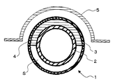
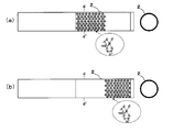
- FIG.1 (a) is a vertical sectional view of a perpendicular direction with respect to the muffler cutter 1 longitudinal direction
- FIG.1 (b) is the longitudinal direction of a muffler cutter
- FIG. 1 (b) is the longitudinal direction of a muffler cutter
- FIG. 1 (b) is the longitudinal direction of a muffler cutter
- FIG. 1 (b) is the longitudinal direction of a muffler cutter
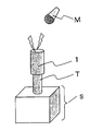
- FIG. It is sectional drawing explaining the usage pattern of the muffler cutter which concerns on this invention.
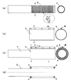
- It is a figure explaining the manufacture example of the muffler cutter which concerns on this invention.
- it is a schematic diagram of a high-temperature reflectance / transmittance measuring device used for measuring emissivity.
- FIG. 10A is an explanatory diagram of a muffler cutter obtained in a reference example of the present invention.
- FIG. 10A is a front view (left view) of the exhaust pipe 2 and a vertical sectional view taken along the line dd ′ of the front view (right view).
- FIG. 10 (b) shows a front view (left view) of the tubular heat shield 3 and a vertical sectional view (right view) taken along the line ee ′ of the front view.
- Fig. 10 (c) is a front view of the muffler cutter in which the tubular heat shield plate 3 shown in Fig. 10 (b) is coaxially fixed to the exhaust pipe 2 shown in Fig. 10 (a) (left figure).
- FIG. 10 (d) shows a vertical sectional view along the longitudinal direction of the muffler cutter shown in FIG. 10 (c). It is.
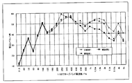
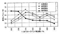
- FIG. 12 shows the exhaust pipe 2 in which a circular through hole is provided in the entire side wall on the downstream side (exhaust gas outflow side). It is a figure which shows the change of the sound pressure level of the tail pipe obtained by the reference example and comparative example of this invention.
- the muffler cutter of the present invention is a muffler cutter attached to a tail pipe of an exhaust system for a vehicle, the exhaust pipe having a plurality of through holes in a side wall, and the exhaust pipe outside the exhaust pipe. And a cylindrical heat insulating plate provided coaxially, and a sound absorbing heat insulating material filled between the exhaust pipe and the cylindrical heat insulating plate, the sound absorbing heat insulating material, Only a part between the exhaust pipe and the cylindrical heat shield is filled in a curved shape, and the other part between the exhaust pipe and the cylindrical heat shield is a curved closure. A space is formed, and the distance between the exhaust pipe forming the closed space and the cylindrical heat shield is 1 to 50 mm.
- FIG. 1 is a cross-sectional view showing an embodiment of a muffler cutter 1 according to the present invention
- FIG. 1 (a) is a vertical cross-sectional view perpendicular to the longitudinal direction of the muffler cutter 1
- FIG. ) Is a vertical cross-sectional view along the longitudinal direction of the muffler cutter 1.
- a muffler cutter 1 has an exhaust pipe 2.
- the exhaust pipe means a tubular material through which exhaust gas (combustion gas) flows, and the exhaust pipe is made of a material corresponding to the temperature of the exhaust gas flowing through the inside, It is preferable to select appropriately from those that can exhibit the desired temperature characteristics and sound absorption characteristics.
- the exhaust pipe those having heat resistance are suitable, and specific examples include a metal pipe and a resin pipe made of a heat-resistant resin, and a metal pipe is preferable.
- a stainless steel tube As the metal tube, a stainless steel tube (SUS tube) is mainly used from the viewpoint of heat resistance and corrosion resistance, but an aluminum tube (aluminum tube) may be used.
- the average thickness of the exhaust pipe is suitably 0.5 to 2.0 mm, more preferably 0.6 to 1.8 mm, and 0.6 to 1.5 mm. It is more appropriate.
- exhaustion means the arithmetic mean value when the thickness of three places is measured with a caliper.
- the outer diameter of the exhaust pipe is suitably 20 to 250 mm, more suitably 20 to 200 mm, even more suitably 25 to 150 mm, and 30 to 100 mm. It is more appropriate.
- the outer diameter of exhaust piping shall mean the value which measured the vertical cross section of exhaust piping with calipers.
- the outer diameter of the exhaust pipe is the maximum length when the vertical cross section of the exhaust pipe is measured with calipers. Shall mean.
- the temperature inside and outside the exhaust pipe can be easily controlled within a suitable range.
- the cross-sectional shape of the exhaust pipe is not particularly limited, and may be circular as shown in the cross-sectional view of FIG.
- the exhaust pipe is provided with a plurality of through holes in the side wall.
- Examples of the shape of the through hole include a circular shape, a square shape, and a slit shape.
- the exhaust pipe provided with the through hole may be formed by appropriately perforating a metal pipe, or may be a commercial product such as a punching metal.
- the exhaust pipe Since the exhaust pipe is provided with a plurality of holes in the side wall in the longitudinal direction, the exhaust pipe has entered a closed space provided between the exhaust pipe and a cylindrical heat shield plate described later. As a result of interference occurring while the exhaust sound reciprocates in the enclosed space, the sound pressure of high-frequency sound is reduced while improving the sound pressure of low-frequency sound (volume of low-frequency sound). It is thought to improve).
- the exhaust pipe is provided with through holes in 1 to 95% when the total outer surface area of the side wall portion where the through holes are to be provided is 100%. More preferably, 20 to 70% are provided with through holes, and more preferably 25 to 50% are provided with through holes.
- the exhaust pipe cannot exhibit sufficient strength, and the exhaust pipe
- the area of the through hole provided in the exhaust pipe is less than 1% of the total outer surface area of the exhaust pipe side wall where the through hole is to be provided, it is difficult to exhibit the effect of improving the volume of low frequency sound and the effect of improving the sound absorption of high frequency sound.
- the “total outer surface area of the side wall portion where the through-hole is to be provided” of the exhaust pipe refers to when the through-hole provided in the outermost peripheral portion is connected among the through-holes provided in the side wall of the exhaust pipe. Means the area of the inner part specified in.
- the through hole provided in the exhaust pipe is preferably provided in the side wall on the downstream side (exhaust gas exhaust side) of the exhaust pipe, and the longitudinal center of the exhaust pipe More preferably, it is provided on the side wall on the downstream side (the side from which the combustion gas is discharged).
- the through hole is provided on the side wall on the upstream side of the exhaust pipe (exhaust gas inflow side)
- the closed hole is provided in a closed space provided between the exhaust pipe and a cylindrical heat shield plate described later.
- the muffler cutter of this invention WHEREIN: It is preferable that the said through-hole is provided in the part facing the sound-absorbing heat insulating material mentioned later at least among the side surfaces of exhaust piping.
- the through hole provided in the side surface of the exhaust pipe is preferably provided so that 50 to 100% of the through hole faces a sound-absorbing heat insulating material described later, and 80 to 100% thereof. Is more preferably provided so as to face a sound-absorbing heat insulating material to be described later, more preferably 90 to 100% is provided so as to face a sound-absorbing heat insulating material described later, 100%) is more preferably provided so as to face a sound-absorbing heat insulating material to be described later.
- the through-hole provided in the side surface of the exhaust pipe is located on the vehicle body side when disposed, for example, when the entire outer surface of the exhaust pipe is divided into two semi-cylindrical parts. More preferably, the semi-cylindrical portion is formed.
- the sound absorption improvement effect of the high frequency sound by the sound absorption heat insulating material can be effectively exhibited, and the higher the ratio of the through holes provided in the part facing the sound absorption heat insulating material, the sound absorption The effect of improving the sound absorption of high frequency sound by the heat insulating material can be more effectively exhibited.
- a muffler cutter 1 As shown in FIG. 1, a muffler cutter 1 according to the present invention has a cylindrical heat shield plate 3 provided coaxially with the exhaust pipe 2 on the outer periphery of the exhaust pipe 2.
- the muffler cutter of the present invention employs a coaxial double circular tubular structure having an exhaust pipe and a cylindrical heat shield plate provided coaxially with the exhaust pipe on the outside of the exhaust pipe. Because the sound diffused to the outside from the side wall of the inner pipe (exhaust pipe) can be reflected and collected by the outer pipe (cylindrical heat shield), a wide range from the low frequency sound range to the high frequency sound range Further, as described above, the exhaust pipe is provided with a plurality of holes on the side wall in the longitudinal direction, thereby causing interference of sound waves, particularly low frequency sound. It is considered that the sound pressure of high-frequency sound can be reduced (the sound-absorbing property of high-frequency sound can be improved) while improving the sound pressure (volume of low-frequency sound).
- the heat shield means that which can suppress the heat radiated from the exhaust gas flowing through the exhaust pipe to the vehicle body side, and is radiated to the vehicle body side. It is preferable to appropriately select from materials made of a material that has heat resistance corresponding to the heat generated and does not deteriorate.
- the cylindrical heat shielding plate those having heat resistance and aesthetics are suitable, and specifically, a metallic one can be mentioned.
- stainless steel As the metal constituting the cylindrical heat shield, stainless steel (SUS) is mainly used from the viewpoints of heat resistance, corrosion resistance, aesthetics and the like, and aluminum may be used. Stainless steel is preferred because of its high properties.
- the cylindrical heat shield plate preferably has an emissivity of 0.1 to 50% at a wavelength of 2 to 15 ⁇ m, more preferably 0.1 to 40%. More preferably, it is 1 to 30%.
- the emissivity of the cylindrical heat shield when the emissivity of the cylindrical heat shield is within the above range, the heat release from the exhaust gas to the vehicle main body side is more effectively suppressed, and the heat deterioration of the vehicle main body is suppressed. It can be easily suppressed.
- emissivity (%) means a value calculated by the following formula.
- Emissivity (%) 100-reflectance (%)-transmittance (%)
- the reflectance (%) and transmittance (%) are electromagnetic waves having a wavelength of 2 to 15 ⁇ m with respect to a measurement sample (heat shield plate) under a temperature condition of 25 ° C. using a high-temperature reflectance / transmittance measuring device.
- Reflectance (%) (reflected light intensity / incident light intensity) ⁇
- Transmittance (%) (transmitted light intensity / incident light intensity) ⁇ 100
- a high-temperature reflectance / transmittance measuring apparatus As a high-temperature reflectance / transmittance measuring apparatus, the one shown schematically in FIG. In the high-temperature reflectivity / transmittance measuring apparatus X shown in FIG. 4, incident light 71 having a wavelength of 2 to 15 ⁇ m irradiated from a Fourier transform infrared spectrophotometer (FT-IR6100 type manufactured by JASCO Corporation) 6 is reflected. Reflected by the mirror 8 and guided into the sample chamber, the sample 10 attached to the center of the turntable 9 is irradiated. The sample 10 is heated by a halogen heater (UL-SH-V500 manufactured by Ushio Electric Co., Ltd.) 11 while being attached to a holder h provided at the center of the turntable 9. The intensity of the reflected light or transmitted light 72 from the sample 10 is detected by a detector 12 that is separately provided on the arm of the turntable 9 having the mounting portion as a rotation axis and circulates around the sample 10.
- FIG. 5 A structural example of the heating part of the high-temperature reflectance / transmittance measuring apparatus X is shown in a sectional view in FIG.
- halogen heaters 11 are installed on the front and back portions of the sample 10, and when the detector 12 captures reflected light or transmitted light from the sample 10, the halogen heater 11 blocks the optical path. It is installed at an angle on the top of the sample 10 so that there is no. When the reflected light or transmitted light is measured, the halogen heater 11 is also rotated together with the sample 10 so that the surface temperature of the sample 10 can always be kept constant. Cooling water 13 is introduced from the outside to the bottom of the turntable 9 on which the sample 10 is installed and the halogen heater 11 to circulate and cool.
- the average thickness of the cylindrical heat shield is suitably 0.5 to 2.0 mm, more suitably 0.6 to 1.8 mm, and 0.6 to 1.5 mm. It is even more appropriate to be.
- the average thickness of a cylindrical heat-shielding board means the arithmetic mean value when measuring the thickness of three places with a caliper.
- the outer diameter of the cylindrical heat shield is suitably 70 to 300 mm, more suitably 120 to 300 mm, even more suitably 125 to 250 mm, 130 to It is more suitable that it is 200 mm.
- the outer diameter of a cylindrical heat shield plate shall mean the value which measured the vertical cross section of the cylindrical heat shield plate with the caliper.
- the outer diameter of the cylindrical heat shield is measured with a caliper. It shall mean the maximum length when the vertical cross section of the cylindrical heat shield is a shape other than a circle. It shall mean the maximum length when
- the temperature inside and outside the heat shield can be easily controlled within a suitable range.
- the cross-sectional shape of the heat shield plate is not particularly limited, and may be substantially circular as shown in FIG.
- the cylindrical heat shield plate 3 includes an upper heat shield plate 3a in which the cylindrical object is halved, and a lower portion in which the cylindrical object is also halved. It is preferable to consist of the heat shield plate 3b. Since the heat shield plate 3 is composed of a half-shaped upper heat shield plate 3a and a half-shaped lower heat shield plate 3b, the muffler cutter of the present invention can be easily manufactured as described later. it can.
- the muffler cutter 1 of the present invention is sound-absorbing only at a part between an exhaust pipe 2 and a cylindrical heat shield 3 provided coaxially with the exhaust pipe 2.
- the heat insulating material 4 is filled in a curved shape (substantially C-shaped), and the other portion between the exhaust pipe 2 and the tubular heat shield plate 3 is curved (substantially C-shaped). ) A closed space S is formed.
- the sound-absorbing heat insulating material means a heat insulating material capable of reducing a sound pressure level at 800 to 20000 Hz at a 1/3 octave band frequency that is annoying for humans among vehicle exhaust sounds.
- glass wool mat glass mat
- silica fiber mat basalt fiber mat
- alumina siliceous fiber mat mullite fiber mat
- alumina fiber mat and other fibrous heat insulation Materials
- the thermal conductivity of the sound-absorbing heat insulating material is preferably 0.01 to 0.1 W / (m ⁇ K) under a temperature condition of 400 ° C., and is preferably 0.001 to 0.00. It is more preferably 08 W / (m ⁇ K), and further preferably 0.001 to 0.06 W / (m ⁇ K).
- the thermal conductivity of the sound-absorbing heat insulating material at room temperature (25 ° C.) is preferably 0.01 to 0.1 W / (m ⁇ K), and 0.001 to 0.08 W. / (M ⁇ K) is more preferable, and 0.001 to 0.06 W / (m ⁇ K) is further more preferable.
- the thermal conductivity means a value measured by a heat flow meter method.
- the sound-absorbing heat insulating material 4 is curved between the exhaust pipe 2 located on the vehicle body 5 side and the tubular heat shield plate 3 when installed. Is preferably filled.
- the heat-absorbing heat insulating material 4 is disposed on the vehicle main body 5 side, whereby thermal deterioration of the vehicle main body 5 due to exhaust heat of the exhaust gas can be more effectively suppressed.
- the thickness of the sound-absorbing heat insulating material is preferably 1 to 50 mm, more preferably 1 to 30 mm, still more preferably 4 to 20 mm, and 4 to 12 mm. More preferably.
- the thickness of a sound-absorbing heat insulating material means an arithmetic average value when thickness is measured at five points using a Peacock dial thickness gauge.
- the sound absorbing property of high frequency sound can be easily improved when filled between the exhaust pipe and the heat shield plate. At the same time, it is possible to more effectively improve the heat insulation by the heat insulating material or the cylindrical heat shield.
- the upper limit of the thickness is filled with the sound absorbing heat insulating material. It is defined by the distance between the exhaust pipe and the cylindrical heat shield.
- the bulk density of the sound-absorbing heat insulating material is preferably 50 to 400 kg / m 3 , more preferably 80 to 350 kg / m 3 , and 100 to 300 kg / m 3. Is more preferable.
- the thickness and bulk density of the sound-absorbing heat insulating material are within the above ranges, so that it is easy to improve the sound-absorbing property of high-frequency sound, and thermal deterioration of the member on the vehicle body side facing the muffler cutter Is easily suppressed, and the temperature inside the exhaust pipe is easily controlled within a certain range.
- the sound-absorbing heat insulating material is filled in a curved shape between the exhaust pipe and the tubular heat shield, but the sound-absorbing heat insulating material is 20% of the total outer surface area of the exhaust pipe. It is preferably set at ⁇ 80%, more preferably set at 30-70%, and further preferably set at 40-60%.
- the installation position of the sound-absorbing heat insulating material and the installation area with respect to the entire outer surface of the exhaust pipe are the shape of the opposing vehicle body side member, the sound-absorbing or heat insulating material to be imparted to the sound-absorbing heat insulating material. What is necessary is just to determine suitably according to sex etc.
- the sound-absorbing heat insulating material for example, when the entire outer surface of the exhaust pipe is divided into two semi-cylindrical parts, It is preferably formed on the entire outer surface. Specifically, as shown by a cross-sectional shape in FIG. 2, when the entire outer surface of the exhaust pipe 2 is divided into two semi-cylindrical parts, the sound-absorbing heat insulating material 4 is located on the vehicle body 5 side. It is preferably formed on substantially the entire outer surface of the cylindrical portion.
- the sound absorbing heat insulating material 4 together with the heat shield plate 3 as described above, when the muffler cutter is attached to the tail pipe of the exhaust system for a vehicle, the exhaust sound that cannot be absorbed by the main muffler or the like is reduced. Heat radiation to the vehicle body 5 side can be effectively suppressed, and thermal deterioration of the components on the vehicle body 5 side can be suitably suppressed.
- a curved closed space S is formed in a part between the exhaust pipe 2 and the cylindrical heat shield plate 3.
- the closed space S is formed in a curved shape between the exhaust pipe 2 and the tubular heat shield plate 3.
- the contact area with the exhaust pipe 2 on the outer surface of the exhaust pipe 2 is 80 to 20% of the total outer surface area of the exhaust pipe 2 (the installation area of the sound absorbing heat insulating material 4 is the total outer surface area of the exhaust pipe 2) Preferably 20 to 80%), preferably 70 to 30% (the installation area of the sound-absorbing heat insulating material 4 is 30 to 70% of the total outer surface area of the exhaust pipe). Is more preferable, and it is more preferable that the sound-absorbing heat insulating material 4 is provided so that the installation area of the sound-absorbing heat insulating material 4 is 40 to 60% of the total outer surface area of the exhaust pipe.
- the closed space means a space defined by the exhaust pipe, the tubular heat insulating material, and the sound absorbing heat insulating material.
- the closed space S is normally hollow (hollow) by the exhaust pipe 2, the tubular heat insulating material 3, and the sound-absorbing heat insulating material 4.
- both ends in the longitudinal direction of the closed space S are usually partitioned from the outside by wall portions.
- the boundary surface formed between the sound-absorbing heat insulating material 4 and the closed space S is not provided with a normal wall portion (partition), and the exhaust gases can move relative to each other.
- the muffler cutter of the present invention employs a substantially coaxial double circular tubular structure having an exhaust pipe and a cylindrical heat shield plate provided coaxially with the exhaust pipe on the outside of the exhaust pipe. Therefore, the sound diffused to the outside from the side wall of the inner pipe (exhaust pipe) can be reflected and collected by the outer pipe (cylindrical heat shield), so that a wide range from the low frequency sound range to the high frequency sound range can be obtained.
- the sound pressure can be increased in a range, and as described above, the exhaust pipe is provided with a plurality of holes in the side wall in the longitudinal direction. It is considered that the sound pressure of the high frequency sound can be lowered (the sound absorption of the high frequency sound can be improved) while improving the sound pressure of the wave sound (volume of the low frequency sound).
- the atmosphere in the enclosed space is preferably an air atmosphere, an inert atmosphere such as nitrogen, or a vacuum, and more preferably an air atmosphere.
- the closed space S may be appropriately filled with a backup material such as glass wool, steel wool, and aluminum wool as long as the effects of the present invention are not impaired.
- the closed space is hollow, and is formed in a curved shape between the exhaust pipe located on the opposite side to the vehicle main body side and the cylindrical heat shield plate when installed. It is preferable that it is made.
- the closed space is formed on the entire outer surface of the semi-cylindrical portion that is located on the side opposite to the vehicle body side when the exhaust pipe is divided into two semi-cylindrical portions. It is preferable that it is formed. Specifically, as shown in a cross-sectional shape in FIG. 2, when the entire outer surface of the exhaust pipe 2 is divided into two semi-cylindrical parts, the closed space S is positioned on the side opposite to the vehicle body 5 side.
- the volume of the low frequency sound can be easily improved when the muffler cutter is attached to the tail pipe of the exhaust system for a vehicle, and the side opposite to the vehicle main body side can be improved. Heat dissipation from the exhaust gas can be easily promoted.
- the distance between the exhaust pipe forming the closed space and the cylindrical heat shield is 1 to 50 mm, preferably 1 to 30 mm, and preferably 4 to 20 mm. More preferably, it is 4 to 12 mm.
- the volume of the low frequency sound can be effectively improved because the distance between the exhaust pipe forming the closed space and the tubular heat shield is within the above range.
- a half-shaped curved sound-absorbing heat-insulating material 4 is prepared, and the sound-absorbing heat-insulating material 4 is divided into half-shaped tubular materials.
- a heat shield plate 3a having a sound absorbing heat insulating material bonded to the inner surface, and a lower heat shield plate 3b having a cylindrical shape halved are arranged so as to wrap around the exhaust pipe 2 and the end portions 3c of the upper heat shield plate 3a and the lower heat shield plate 3b are butted together, and the two are welded and joined by butt welding or the like.
- An example is a method in which a flange or the like is separately provided on 3c and connected by a connecting member (not shown) such as a bolt.
- a connecting member such as a bolt.
- the constituent material of the sound-absorbing heat insulating material is arranged between the exhaust pipe and the tubular heat shield in a state in which the tubular heat shield plate is disposed on the outer periphery of the exhaust pipe. Examples of the method include making a press-fitting at a desired position between the plates and filling and forming a sound-absorbing heat insulating material.
- the distance from the vehicle body side member is 0 to 50 mm, preferably 1 to 50 mm. It is more preferable to dispose in the range of 1 to 40 mm, still more preferable to dispose in the range of 1 to 35 mm.
- Specific examples of the member on the vehicle body side include a bumper. Since the muffler cutter of the present invention can suppress heat radiation to the vehicle main body side and has excellent heat insulation properties, the distance from the vehicle main body side member can be reduced.
- Specific examples of vehicles to which the muffler cutter of the present invention is attached include automobiles and motorcycles.
- a high-frequency sound that is annoying to humans is selectively reduced by filling a part between the exhaust pipe and the tubular heat shield with the sound-absorbing heat insulating material.
- the other part between the exhaust pipe and the cylindrical heat shield plate is a curved closed space, and the distance between the exhaust pipe and the cylindrical heat shield plate forming the closed space is set to a predetermined distance.
- the present invention by providing a cylindrical heat shield plate coaxially with the exhaust pipe on the outside of the exhaust pipe, even when a high-temperature fluid circulates inside the exhaust pipe, Radiation heat transfer to the outside can be suitably suppressed, and the sound absorbing heat insulating material is filled by filling a part between the exhaust pipe and the tubular heat shield plate with the sound absorbing heat insulating material.
- a radiant heat transfer difference from the closed space side can be generated, and the heat can be selectively dissipated from the closed space side.
- the muffler cutter of the present invention can be suitably used as a constituent member of a tail pipe.
- the tail pipe having the muffler cutter of the present invention preferably has a total length excluding the length of the muffler cutter part of 50 to 500 mm, more preferably 50 to 300 mm, and still more preferably 50 to 200 mm. .
- the total length excluding the length of the muffler cutter portion is an exhaust system for a vehicle in which the muffler cutter 1 is attached to the end of the tail pipe body as shown in FIG.
- the length L of the tail pipe T excluding the muffler cutter 1 portion is meant.
- the muffler cutter of the present invention when the total length excluding the length of the muffler cutter is within the above range, the muffler cutter of the present invention and the sound quality improvement effect of the exhaust sound are appropriately exhibited. be able to.
- the attachment of the muffler cutter to the tail pipe can be performed by welding or the like as appropriate.
- the attachment may be performed at the time of assembly of the vehicle in the factory, or at any time after the vehicle is shipped from the factory. Good.
- the present invention it is possible to selectively reduce only high-frequency sound that is annoying to humans, and in particular, to selectively improve the volume of low-frequency sound that occurs during idling, thereby providing excellent heat insulation and noise reduction and exhaust sound. It is possible to provide a muffler cutter that can improve the sound quality.
- the exhaust pipe 2 is a punched metal SUS pipe (inner diameter 52 mm, outer diameter 54 mm, thermal conductivity 27 W / () with a plurality of openings provided in the entire side wall in the longitudinal direction. m ⁇ K) (400 ° C.)), and a SUS pipe (inner diameter 66 mm) comprising an upper heat shield 3a and a lower heat shield 3b in which a cylindrical object is halved as a heat shield 3 on the cylinder. And an outer diameter of 68 mm, a thermal conductivity of 27 W / (m ⁇ K) (400 ° C.), and an emissivity of 0.3 at a wavelength of 2 to 15 ⁇ m.
- the upper heat shield 3a and the upper heat shield 3a In a state where the end portions 3c and 3c of the lower heat shield plate 3b are butted together, the sound-absorbing heat insulating material 4 is formed into a tubular shape with the exhaust pipe 2 as shown in FIG.
- the heat insulation plate 3 (3a) is filled in a curved shape, and a part between the exhaust pipe 2 and the tubular heat insulation plate 3 (3b) is filled with a sound absorbing heat insulating material.
- a muffler cutter 1 having a closed space S that is a curved hollow portion and a distance between the exhaust pipe 2 forming the closed space S and the tubular heat shield 3 (3b) being 6 mm is manufactured. did.
- an SUS tube (inner diameter 66 mm, outer diameter 68 mm, thermal conductivity 27 W / (m ⁇ K) (400 ° C.), emissivity 0.3 at a wavelength of 2 to 15 ⁇ m) is prepared as a tail pipe body, and FIG.
- the muffler cutter 1 was welded to the end of the tail pipe body so as to be coaxial with the tail pipe body.
- the total length L of the tail pipe T excluding the muffler cutter 1 portion was 160 mm.
- the exhaust pipe 2 is a punched metal SUS pipe (inner diameter 52 mm, outer diameter 54 mm, thermal conductivity 27 W / () with a plurality of openings provided in the entire side wall in the longitudinal direction. m ⁇ K) (400 ° C.)), and as the heat shield 3 on the cylinder, a SUS tube (inner diameter 86 mm) comprising an upper heat shield 3a and a lower heat shield 3b in which a cylindrical object is halved. And an outer diameter of 88 mm, a thermal conductivity of 27 W / (m ⁇ K) (400 ° C.), and an emissivity of 0.3 at a wavelength of 2 to 15 ⁇ m.
- the upper heat shield 3a and the upper heat shield 3a In a state where the end portions 3c and 3c of the lower heat shield plate 3b are butted together, the sound-absorbing heat insulating material 4 is formed into a tubular shape with the exhaust pipe 2 as shown in FIG.
- the heat insulation plate 3 (3a) is filled in a curved shape, and a part between the exhaust pipe 2 and the tubular heat insulation plate 3 (3b) is filled with a sound absorbing heat insulating material.
- a muffler cutter 1 having a closed space S that is a curved hollow portion and a distance between the exhaust pipe 2 forming the closed space S and the cylindrical heat shield 3 (3b) being 16 mm is manufactured. did.
- a SUS tube (inner diameter 52 mm, outer diameter 54 mm, thermal conductivity 27 W / (m ⁇ K) (400 ° C.), emissivity 0.3 at a wavelength of 2 to 15 ⁇ m) is prepared as a tail pipe body, and FIG.
- the muffler cutter 1 was welded to the end of the tail pipe body so as to be coaxial with the tail pipe body.
- the total length L of the tail pipe T excluding the muffler cutter 1 portion was 160 mm.
- the sound pressure change was evaluated in the same manner as in Example 1. The results are shown in Table 1 and FIG.
- Example 1 (Comparative Example 1) In Example 1, instead of the muffler cutter 1, a single tube (inner diameter: 52 mm, outer diameter: 54 mm, thermal conductivity: 27 W / (m ⁇ K) (400 ° C.)) was used in the same manner as in Example 1. A tail pipe T was produced. In the obtained tail pipe T, the sound pressure change was evaluated in the same manner as in Example 1. The results are shown in Table 1 and FIG.
- the tail pipe obtained in Example 1 and Example 2 has a coaxial double pipe structure of an exhaust pipe 2 provided with a through hole and a cylindrical heat shield plate 3, and the exhaust pipe is exhausted.
- a comparative example is obtained by partially filling the sound absorbing heat insulating material 4 in a curved shape between the pipe 2 and the tubular heat shield plate 3.
- the sound pressure level can be reduced as compared with the single pipe used in 2 and only the high-frequency sound that is annoying to humans is selectively reduced, and the exhaust pipe 2 provided with a through hole and the cylindrical heat shield plate
- the other part between the three and the third is a curved closed space S, and the distance between the exhaust pipe forming the closed space S and the cylindrical heat shield is controlled to a predetermined distance.
- the sound pressure level in the low frequency region of 100 to 200 Hz from the single tube used Can be above, it can be seen that the volume of low-frequency noise generated at the time of high user preference idling can be selectively emphasized.
- Example 1 A muffler cutter was produced in the same manner as in Example 1 except that the sound-absorbing heat insulating material 4 was not used in Example 1, and then a tail pipe was produced in the same manner as in Example 1. In the obtained tail pipe, the change in sound pressure was evaluated in the same manner as in Example 1. The results are shown in Table 2 and FIG. In Table 2 and FIG. 9, the results of Comparative Example 1 are also shown for comparison.
- Example 2 In Example 1, the sound absorbing heat insulating material 4 is not used, and the plurality of openings provided in the entire side wall in the longitudinal direction of the SUS pipe used as the exhaust pipe 2 are made of aluminum tape (heat-resistant aluminum tape manufactured by Sliontec). A muffler cutter was produced in the same manner as in Example 1 except that the tail pipe was closed, and then a tail pipe was produced in the same manner as in Example 1. In the obtained tail pipe, the change in sound pressure was evaluated in the same manner as in Example 1. The results are shown in Table 2 and FIG.
- the tail pipe obtained in Reference Example 1 is an exhaust pipe having a punching hole as a muffler cutter.
- the sound pressure level tends to increase, particularly in the low frequency region of 100 to 200 Hz. I understand that. *
- FIG. 10 is an explanatory view of the muffler cutter produced in this reference example.
- FIG. 10 (a) is a front view of the exhaust pipe 2 (left figure) and a vertical sectional view taken along the line dd ′ of the front view (FIG. 10).
- FIG. 10 (b) shows a front view (left view) of the tubular heat shield 3 and a vertical sectional view (right view) taken along the line ee ′ of the front view.
- FIG. 10C is a front view of the muffler cutter in which the tubular heat shield plate 3 shown in FIG. 10B is coaxially fixed to the exhaust pipe 2 shown in FIG. ) And a front sectional view taken along line ff ′ (right diagram), FIG.
- FIG. 10 (d) shows a vertical sectional view along the longitudinal direction of the muffler cutter shown in FIG. 10 (c).
- a SUS single tube outer diameter 54 mm, plate thickness 0.4 mm, length 340 mm, thermal conductivity 27 W / (m ⁇ K) (400 ° C.)
- a punching metal-like exhaust pipe 2 is formed at one end of the single pipe by providing 576 circular through holes (diameter 3 mm) at intervals of 5 mm on the entire side wall in the longitudinal direction. did.
- FIG. 10 (a) shows a SUS single tube (outer diameter 54 mm, plate thickness 0.4 mm, length 340 mm, thermal conductivity 27 W / (m ⁇ K) (400 ° C.)
- an SUS tube (outer diameter 72 mm, plate thickness 1.0 mm, thermal conductivity 27 W / (m ⁇ K) having a fastening fixing ear M. ) (400 ° C.) emissivity 0.3 at a wavelength of 2 to 15 ⁇ m) and two aluminum ring spacers (outer diameter 70 mm, inner diameter 54 mm, thickness 10 mm) were prepared.
- a tubular heat shield plate 3 is arranged on the outer surface of the exhaust pipe 2 via a ring-shaped spacer s, and then provided on the heat shield plate 3.
- the exhaust pipe 2 and the tubular heat shield plate 3 are connected to the end of the tail pipe T at a distance of 16 mm by tightening and fixing the bolts in the bolt holes provided in the ear M provided in the hot plate 3.
- a muffler cutter 1 fixed while being separated was produced.
- the sound pressure change was evaluated in the same manner as in Reference Example 3. The results are shown in Table 3 and FIG.
- the exhaust pipe 2 and the cylindrical heat shield plate 3 are connected to the end of the tail pipe T at a distance of 45 mm by tightening and fixing the bolts in the bolt holes provided in the ears M provided in the hot plate 3.
- a muffler cutter 1 fixed while being separated was produced.
- the sound pressure change was evaluated in the same manner as in Reference Example 3. The results are shown in Table 3 and FIG.
- the tail pipes obtained in Reference Example 3 to Reference Example 5 have a coaxial double pipe structure of an exhaust pipe 2 provided with a through hole and a cylindrical heat shield plate 3.
- the sound pressure level can be reduced as compared with the single tube used in Comparative Example 2, and only the high frequency sound that is annoying to humans is selectively reduced, and the exhaust pipe 2 and Comparative Example 2 by providing a curved closed space between the tubular heat shield plate 3 and controlling the distance between the exhaust pipe forming the closed space and the tubular heat shield plate to a predetermined distance. It can be seen that the sound pressure level can be improved in the low frequency region of 200 Hz as compared with the single tube used in the above, and the volume of the low frequency sound generated during idling with high user preference can be selectively emphasized.
- Reference Example 6 In Reference Example 5, except that a SUS single tube (outer diameter 54 mm, plate thickness 1.0 mm, length 340 mm, thermal conductivity 27 W / (m ⁇ K) (400 ° C.)) was not provided with a circular through hole.
- a muffler cutter 1 in which the exhaust pipe 2 and the tubular heat shield 3 were fixed to the end of the tail pipe T while being separated by a distance of 45 mm was produced.
- the sound pressure change was evaluated in the same manner as in Reference Example 3. The results are shown in Table 4 and FIG. In Table 4 and FIG. 13, the results of Reference Example 5 and Comparative Example 2 are also shown for comparison.
- FIG. 7 In Reference Example 5, at one end of a SUS single tube (outer diameter 54 mm, plate thickness 1.0 mm, length 340 mm, thermal conductivity 27 W / (m ⁇ K) (400 ° C.)), FIG. As shown in Fig. 5, the reference example is used except that 288 circular through holes (diameter 3 mm) are provided at intervals of 5 mm on the entire side wall on the upstream side (exhaust gas inflow side) of the exhaust pipe 2. 5, a muffler cutter 1 in which the exhaust pipe 2 and the cylindrical heat shield 3 were fixed to the end of the tail pipe T while being separated by a distance of 45 mm was produced. In the obtained tail pipe T, the sound pressure change was evaluated in the same manner as in Reference Example 3. The results are shown in Table 4 and FIG.
- FIG. 5 In Reference Example 5, at one end of a SUS single tube (outer diameter 54 mm, plate thickness 1.0 mm, length 340 mm, thermal conductivity 27 W / (m ⁇ K) (400 ° C.)), FIG. As shown in FIG. 5, the reference example is used except that 288 circular through holes (diameter 3 mm) are provided at intervals of 5 mm on the entire downstream side wall of the exhaust pipe 2 (exhaust gas outflow side). 5, a muffler cutter 1 in which the exhaust pipe 2 and the cylindrical heat shield 3 were fixed to the end of the tail pipe T while being separated by a distance of 45 mm was produced. In the obtained tail pipe T, the sound pressure change was evaluated in the same manner as in Reference Example 3. The results are shown in Table 4 and FIG.
- the tail pipe obtained in Reference Example 6 has a coaxial double pipe structure of the exhaust pipe 2 having no through hole and the cylindrical heat shield plate 3. It can be seen that the sound pressure level can be improved over the entire measurement frequency than the single tube used in Comparative Example 2.
- the tail pipes obtained in Reference Example 5, Reference Example 7 and Reference Example 8 are exhaust pipes having a coaxial double pipe structure of an exhaust pipe 2 having a through hole and a cylindrical heat shield. Comparative Example 2 and Reference Example in the high frequency region of 800 Hz by controlling the distance between the exhaust pipe formed between the tube 2 and the tubular heat shield plate 3 and the tubular heat shield plate to a predetermined distance.
- the sound pressure level can be reduced more than 6 and only high-frequency sound that is harsh to human beings can be selectively reduced, and the sound pressure level can be improved in the low frequency region of 200 Hz than Comparative Example 2 and Reference Example 6. It can be seen that the volume of low frequency sound generated during idling with high user preference can be selectively emphasized. Furthermore, when comparing the tail pipe obtained in Reference Example 7 and the tail pipe obtained in Reference Example 8, the tail pipe obtained in Reference Example 7 is compared with the tail pipe obtained in Reference Example 8, It can be seen that the sound pressure level is lowered overall.
- the muffler cutter 1 obtained in Example 1 can sufficiently reduce the temperature rise of the bumper surface as compared with a hollow double tube not filled with a sound absorbing heat insulating material. . Moreover, from Table 5, the muffler cutter 1 obtained in Example 1 is formed by filling a sound-absorbing heat insulating material only in a part between the exhaust pipe and the tubular heat shield. Regardless, the heat radiation to the bumper side is suppressed to the same level or more as a muffler cutter (full-filled double pipe) in which the entire space formed between the exhaust pipe and the cylindrical heat shield is filled with sound-absorbing heat insulating material. And it turns out that the temperature rise of a bumper surface can be reduced.
- the present invention it is possible to provide a muffler cutter that is excellent in heat insulation and noise reduction and can improve the sound quality of exhaust sound. Moreover, according to this invention, the tail pipe formed by mounting
Abstract
Provided is a muffler cutter having excellent heat-insulating and sound-damping properties, and capable of improving the quality of the exhaust sound. This muffler cutter (1), which is mounted on a tail pipe in a vehicle exhaust system, is characterized by being equipped with an exhaust pipe (2) in the side wall of which multiple through-holes are provided, a cylindrical heat shield plate (3) provided on the outside of and coaxial with the exhaust pipe, and a sound-absorbent, heat-insulating material (4) arranged in the interval between the exhaust pipe and the cylindrical heat shield plate, with the sound-absorbent, heat-insulating material filling only a portion of the interval between the exhaust pipe and the cylindrical heat shield plate in a curved shape, and a curved closed space (S) being formed in the other portion of the interval between the exhaust pipe and the cylindrical heat shield plate, and the distance between the exhaust pipe and the cylindrical heat shield plate forming the closed space being 1-50 mm.
Description
本発明は、マフラーカッターに関する。
The present invention relates to a muffler cutter.
自動車エンジンから排出される燃焼ガス(排気ガス)は、エンジンに対して順次接続された、エキゾーストマニフォールド、エキマニ直下型触媒コンバータ、フロントチューブ、床下触媒コンバータ、センターマフラー、メインマフラー等を経て、最終的にテールパイプの端部(テールエンド)から外部に放出される(例えば、特許文献1(特開2008-190371号公報)参照)。
Combustion gas (exhaust gas) discharged from the car engine is finally connected to the engine through exhaust manifold, exhaust manifold direct catalytic converter, front tube, underfloor catalytic converter, center muffler, main muffler, etc. It is discharged to the outside from the end (tail end) of the tail pipe (see, for example, Patent Document 1 (Japanese Patent Laid-Open No. 2008-190371)).
上記自動車に配設されるメインマフラー等の排気系配管の大部分は、車輌底部に配置されることから通常ユーザーに視認されることはないが、排気系配管の末端に位置するテールパイプは、車輌後部のバンパー下部から端部(テールエンド)が露出するために、ユーザーに視認され易く車輌の美観に与える影響が大きい。
Most of the exhaust system piping such as the main muffler disposed in the automobile is not usually visible to the user because it is disposed at the bottom of the vehicle, but the tail pipe located at the end of the exhaust system piping is Since the end portion (tail end) is exposed from the bottom of the bumper at the rear of the vehicle, it is easily visible to the user and has a great influence on the appearance of the vehicle.
このため、一般にテールパイプの端部にさらにマフラーカッターを装着することが行われており、このマフラーカッターによって、車輌の美観や高級感を向上させることが行われている。
For this reason, a muffler cutter is generally attached to the end of the tail pipe, and the aesthetics and luxury of the vehicle are improved by this muffler cutter.
ところで、高排気量の車輌等においては排気音が大きくなり易く、メインマフラー等に対する負荷が大きくなり易いことから、メインマフラー等で吸収しきれない排気音を低減し、排気音による騒音を緩和し得るマフラーカッターが望まれるようになっている。
By the way, in a high displacement vehicle, etc., the exhaust noise is likely to increase, and the load on the main muffler etc. is likely to increase. Therefore, the exhaust noise that cannot be absorbed by the main muffler, etc. is reduced, and the noise caused by the exhaust noise is reduced. Obtaining muffler cutters are becoming desirable.
一方、単に車輌の排気音を低減するだけでは、アイドリング音等の排気音を嗜好するユーザーを満足させることができないことから、マフラーカッターとしては、消音性に優れるとともに排気音の音質を向上し得る、二律背反した目的を達成し得るものが求められるようになっている。
On the other hand, simply reducing the exhaust sound of a vehicle cannot satisfy users who like exhaust sounds such as idling sounds. Therefore, as a muffler cutter, the sound quality of the exhaust sound can be improved as well as being excellent in silence. There is a demand for something that can achieve a contradictory purpose.
従って、本発明は、断熱性および消音性に優れるとともに排気音の音質を向上し得るマフラーカッターを提供することを目的とするものである。
Therefore, an object of the present invention is to provide a muffler cutter that is excellent in heat insulating properties and sound deadening properties and can improve the sound quality of exhaust sound.
上記技術課題を解決するために、本発明者等が鋭意検討を行った結果、車輌排気音のうち、人間にとって耳障りな高周波音のみを選択的に低減するとともに、逆にユーザーの嗜好性の高いアイドリング時に発生する低周波音については選択的に強調させ得るマフラーカッターによって上記目的を達成し得ることを着想した。
上記着想に基づいて本発明者等がさらに鋭意検討を行ったところ、車輌用排気系のテールパイプに装着されるマフラーカッターであって、側壁に複数の貫通孔が設けられた排気用配管と、該排気用配管の外側に該排気用配管と同軸状に設けられた筒状の遮熱板と、前記排気用配管と筒状の遮熱板との間に充填された吸音性断熱材とを有し、前記吸音性断熱材は、前記排気用配管と筒状の遮熱板との間の一部にのみ湾曲状に充填されるとともに、前記排気用配管と筒状の遮熱板との間の他の部分には湾曲状の閉鎖空間が形成されてなり、前記閉鎖空間を形成する排気用配管と筒状の遮熱板との距離が1~50mmであるマフラーカッターにより、上記技術課題を解決し得ることを見出し、本知見に基づいて本発明を完成するに至った。 As a result of intensive studies by the present inventors to solve the above technical problem, it is possible to selectively reduce only high-frequency sound that is annoying to humans among vehicle exhaust sound, and conversely, high user preference. It was conceived that the low-frequency sound generated during idling can be achieved by a muffler cutter that can be selectively emphasized.
Based on the above idea, the present inventors conducted further diligent studies, a muffler cutter attached to a tail pipe of a vehicle exhaust system, and an exhaust pipe provided with a plurality of through holes on a side wall; A cylindrical heat shield provided coaxially with the exhaust pipe on the outside of the exhaust pipe, and a sound-absorbing heat insulating material filled between the exhaust pipe and the cylindrical heat shield. And the sound-absorbing heat insulating material is curvedly filled only in a portion between the exhaust pipe and the cylindrical heat shield plate, and the exhaust pipe and the cylindrical heat shield plate A curved closed space is formed in the other part of the space, and the muffler cutter in which the distance between the exhaust pipe forming the closed space and the cylindrical heat shield plate is 1 to 50 mm. The inventors have found that the present invention can be solved, and have completed the present invention based on this finding.
すなわち、本発明は、
(1)車輌用排気系のテールパイプに装着されるマフラーカッターであって、
側壁に複数の貫通孔が設けられた排気用配管と、該排気用配管の外側に該排気用配管と同軸状に設けられた筒状の遮熱板と、前記排気用配管と筒状の遮熱板との間に充填された吸音性断熱材とを有し、
前記吸音性断熱材は、前記排気用配管と筒状の遮熱板との間の一部にのみ湾曲状に充填されるとともに、前記排気用配管と筒状の遮熱板との間の他の部分には湾曲状の閉鎖空間が形成されてなり、
前記閉鎖空間を形成する排気用配管と筒状の遮熱板との距離が1~50mmである
ことを特徴とするマフラーカッター、
(2)前記貫通孔が、前記排気用配管の側面のうち少なくとも前記吸音性断熱材に対向する部分に設けられている上記(1)に記載のマフラーカッター、
(3)前記吸音性断熱材が、配設時に車輌本体側に位置する前記排気用配管と筒状の遮熱板との間に湾曲状に充填される上記(1)に記載のマフラーカッター、
(4)前記吸音性断熱材が、配設時に車輌本体側に位置する前記排気用配管と筒状の遮熱板との間に湾曲状に充填される上記(2)に記載のマフラーカッター、
(5)前記閉鎖空間が、中空状になっており、配設時に車輌本体側とは反対側に位置する前記排気用配管と筒状の遮熱板との間に湾曲状に形成されてなる上記(3)に記載のマフラーカッター、
(6)前記閉鎖空間が、中空状になっており、配設時に車輌本体側とは反対側に位置する前記排気用配管と筒状の遮熱板との間に湾曲状に形成されてなる上記(4)に記載のマフラーカッター、および
(7)前記吸音性断熱材の400℃の温度条件下における熱伝導率が0.01~0.1W/(m・K)である上記(1)~(6)のいずれかに記載のマフラーカッター
を提供するものである。 That is, the present invention
(1) A muffler cutter attached to a tail pipe of a vehicle exhaust system,
An exhaust pipe having a plurality of through holes in the side wall; a cylindrical heat shield plate provided coaxially with the exhaust pipe on the outside of the exhaust pipe; and the exhaust pipe and the cylindrical shield. A sound-absorbing heat insulating material filled between the heat plate and
The sound-absorbing heat insulating material is filled in a curved shape only in a part between the exhaust pipe and the cylindrical heat shield plate, and other than between the exhaust pipe and the cylindrical heat shield plate. A curved closed space is formed in this part,
A muffler cutter, wherein a distance between the exhaust pipe forming the closed space and the cylindrical heat shield is 1 to 50 mm;
(2) The muffler cutter according to (1), wherein the through-hole is provided in at least a portion of the side surface of the exhaust pipe facing the sound-absorbing heat insulating material.
(3) The muffler cutter according to the above (1), wherein the sound-absorbing heat insulating material is filled in a curved shape between the exhaust pipe located on the vehicle main body side and a cylindrical heat shield when disposed.
(4) The muffler cutter according to (2), wherein the sound-absorbing heat insulating material is filled in a curved shape between the exhaust pipe located on the vehicle main body side and a cylindrical heat shield when disposed.
(5) The closed space is hollow, and is formed in a curved shape between the exhaust pipe located on the side opposite to the vehicle main body side and the cylindrical heat shield when disposed. The muffler cutter according to (3) above,
(6) The closed space is hollow, and is formed in a curved shape between the exhaust pipe located on the side opposite to the vehicle body side when installed and the cylindrical heat shield. The muffler cutter according to the above (4), and (7) the thermal conductivity under the temperature condition of 400 ° C. of the sound absorbing heat insulating material is 0.01 to 0.1 W / (m · K) (1) A muffler cutter according to any one of (6) to (6) is provided.
本発明によれば、排気用配管と筒状の遮熱板との間の一部を湾曲状の閉鎖空間とし、該閉鎖空間を形成する排気用配管と筒状の遮熱板との距離を所定距離に制御することによってユーザーの嗜好性の高いアイドリング時に発生する低周波音の音量を選択的に強調させ、人間にとって耳障りな高周波音のみを選択的に低減するとともに、排気用配管と筒状の遮熱板との間の他の部分に吸音性断熱材が充填されてなるものであることによって上記高周波音をさらに低減することができ、このために、断熱性および消音性に優れるとともに排気音の音質を向上し得るマフラーカッターを提供することができる。
According to the present invention, a part between the exhaust pipe and the cylindrical heat shield is a curved closed space, and the distance between the exhaust pipe and the cylindrical heat shield forming the closed space is set. By controlling to a predetermined distance, the volume of low-frequency sound generated during idling, which is highly user-friendly, is selectively emphasized, and only high-frequency sound that is annoying to humans is selectively reduced. The high-frequency sound can be further reduced by filling the other part between the heat shield plate and the heat-absorbing heat-insulating material. A muffler cutter capable of improving the sound quality of sound can be provided.
本発明のマフラーカッターは、車輌用排気系のテールパイプに装着されるマフラーカッターであって、側壁に複数の貫通孔が設けられた排気用配管と、該排気用配管の外側に該排気用配管と同軸状に設けられた筒状の遮熱板と、前記排気用配管と筒状の遮熱板との間に充填された吸音性断熱材とを有し、前記吸音性断熱材は、前記排気用配管と筒状の遮熱板との間の一部にのみ湾曲状に充填されるとともに、前記排気用配管と筒状の遮熱板との間の他の部分には湾曲状の閉鎖空間が形成されてなり、前記閉鎖空間を形成する排気用配管と筒状の遮熱板との距離が1~50mmであることを特徴とするものである。
The muffler cutter of the present invention is a muffler cutter attached to a tail pipe of an exhaust system for a vehicle, the exhaust pipe having a plurality of through holes in a side wall, and the exhaust pipe outside the exhaust pipe. And a cylindrical heat insulating plate provided coaxially, and a sound absorbing heat insulating material filled between the exhaust pipe and the cylindrical heat insulating plate, the sound absorbing heat insulating material, Only a part between the exhaust pipe and the cylindrical heat shield is filled in a curved shape, and the other part between the exhaust pipe and the cylindrical heat shield is a curved closure. A space is formed, and the distance between the exhaust pipe forming the closed space and the cylindrical heat shield is 1 to 50 mm.
以下、本発明のマフラーカッターについて、適宜図面を参照しつつ説明するものとする。
図1は、本発明に係るマフラーカッター1の実施態様例を示す断面図であり、図1(a)はマフラーカッター1の長手方向に対して直角方向の垂直断面図であり、図1(b)はマフラーカッター1の長手方向に沿った垂直断面図である。 Hereinafter, the muffler cutter of the present invention will be described with reference to the drawings as appropriate.
FIG. 1 is a cross-sectional view showing an embodiment of amuffler cutter 1 according to the present invention, and FIG. 1 (a) is a vertical cross-sectional view perpendicular to the longitudinal direction of the muffler cutter 1, and FIG. ) Is a vertical cross-sectional view along the longitudinal direction of the muffler cutter 1.
図1は、本発明に係るマフラーカッター1の実施態様例を示す断面図であり、図1(a)はマフラーカッター1の長手方向に対して直角方向の垂直断面図であり、図1(b)はマフラーカッター1の長手方向に沿った垂直断面図である。 Hereinafter, the muffler cutter of the present invention will be described with reference to the drawings as appropriate.
FIG. 1 is a cross-sectional view showing an embodiment of a
図1に示すように、本発明に係るマフラーカッター1は、排気用配管2を有している。
本出願書類において、排気用配管とは、内部を排気ガス(燃焼ガス)が流通する管状物を意味し、排気用配管としては、内部を流通する排気ガスの温度等に対応した材質からなり、目的とする温度特性や吸音特性を発揮し得るものから適宜選択することが好ましい。
上記排気用配管としては耐熱性を有するものが好適であり、具体的には、金属管や耐熱性樹脂からなる樹脂管を挙げることができ、金属管であることが好ましい。 As shown in FIG. 1, amuffler cutter 1 according to the present invention has an exhaust pipe 2.
In the present application documents, the exhaust pipe means a tubular material through which exhaust gas (combustion gas) flows, and the exhaust pipe is made of a material corresponding to the temperature of the exhaust gas flowing through the inside, It is preferable to select appropriately from those that can exhibit the desired temperature characteristics and sound absorption characteristics.
As the exhaust pipe, those having heat resistance are suitable, and specific examples include a metal pipe and a resin pipe made of a heat-resistant resin, and a metal pipe is preferable.
本出願書類において、排気用配管とは、内部を排気ガス(燃焼ガス)が流通する管状物を意味し、排気用配管としては、内部を流通する排気ガスの温度等に対応した材質からなり、目的とする温度特性や吸音特性を発揮し得るものから適宜選択することが好ましい。
上記排気用配管としては耐熱性を有するものが好適であり、具体的には、金属管や耐熱性樹脂からなる樹脂管を挙げることができ、金属管であることが好ましい。 As shown in FIG. 1, a
In the present application documents, the exhaust pipe means a tubular material through which exhaust gas (combustion gas) flows, and the exhaust pipe is made of a material corresponding to the temperature of the exhaust gas flowing through the inside, It is preferable to select appropriately from those that can exhibit the desired temperature characteristics and sound absorption characteristics.
As the exhaust pipe, those having heat resistance are suitable, and specific examples include a metal pipe and a resin pipe made of a heat-resistant resin, and a metal pipe is preferable.
金属管としては、耐熱性や耐食性の観点からステンレス鋼製のもの(SUS管)が主に使用されるが、アルミニウム製のもの(アルミ管)であってもよい。
As the metal tube, a stainless steel tube (SUS tube) is mainly used from the viewpoint of heat resistance and corrosion resistance, but an aluminum tube (aluminum tube) may be used.
排気用配管の平均厚みは、0.5~2.0mmであることが適当であり、0.6~1.8mmであることがより適当であり、0.6~1.5mmであることがさらに適当である。
なお、本出願書類において、排気用配管の平均厚みは、ノギスにより3箇所の厚みを測定したときの算術平均値を意味する。 The average thickness of the exhaust pipe is suitably 0.5 to 2.0 mm, more preferably 0.6 to 1.8 mm, and 0.6 to 1.5 mm. It is more appropriate.
In addition, in this application document, the average thickness of piping for exhaust_gas | exhaustion means the arithmetic mean value when the thickness of three places is measured with a caliper.
また、排気用配管の外径は、20~250mmであることが適当であり、20~200mmであることがより適当であり、25~150mmであることがさらに適当であり、30~100mmであることが一層適当である。
なお、本出願書類において、排気用配管の外径は、排気用配管の垂直断面をノギスにより測定した値を意味するものとする。また、本出願書類において、排気用配管の垂直断面が円形以外の形状である場合には、排気用配管の外径とは、排気用配管の垂直断面をノギスにより測定したときの最大長さを意味するものとする。 Further, the outer diameter of the exhaust pipe is suitably 20 to 250 mm, more suitably 20 to 200 mm, even more suitably 25 to 150 mm, and 30 to 100 mm. It is more appropriate.
In addition, in this application document, the outer diameter of exhaust piping shall mean the value which measured the vertical cross section of exhaust piping with calipers. In addition, in the present application documents, when the vertical cross section of the exhaust pipe has a shape other than a circle, the outer diameter of the exhaust pipe is the maximum length when the vertical cross section of the exhaust pipe is measured with calipers. Shall mean.
排気用配管の平均厚みや外径が上記範囲内にあることにより、排気用配管の内部および外部の温度を好適な範囲に制御し易くなる。
When the average thickness and outer diameter of the exhaust pipe are within the above ranges, the temperature inside and outside the exhaust pipe can be easily controlled within a suitable range.
排気用配管の断面形状としても特に制限されず、図1(a)に断面図で示すように円形であってもよいし、楕円形等であってもよい。
The cross-sectional shape of the exhaust pipe is not particularly limited, and may be circular as shown in the cross-sectional view of FIG.
本発明のマフラーカッターにおいて、排気用配管は、側壁に複数の貫通孔が設けられてなるものである。
貫通孔の形状としては、円形状、四角形状、スリット状等の形状を挙げることができる。
上記貫通孔を設けた排気用配管としては、金属管に適宜穿孔してなるものであってもよいし、パンチングメタル等の市販品であってもよい。 In the muffler cutter of the present invention, the exhaust pipe is provided with a plurality of through holes in the side wall.
Examples of the shape of the through hole include a circular shape, a square shape, and a slit shape.
The exhaust pipe provided with the through hole may be formed by appropriately perforating a metal pipe, or may be a commercial product such as a punching metal.
排気用配管が、その長手方向の側壁に複数の孔が設けられてなるものであることにより、上記排気用配管と後述する筒状の遮熱板との間に設けられる閉鎖空間内に侵入した排気音が閉鎖空間内を往復する間に干渉を生じる結果、特に低周波音の音圧(低周波音の音量)を向上させつつ、高周波音の音圧を低下させる(高周波音の吸音性を向上させる)と考えられる。
Since the exhaust pipe is provided with a plurality of holes in the side wall in the longitudinal direction, the exhaust pipe has entered a closed space provided between the exhaust pipe and a cylindrical heat shield plate described later. As a result of interference occurring while the exhaust sound reciprocates in the enclosed space, the sound pressure of high-frequency sound is reduced while improving the sound pressure of low-frequency sound (volume of low-frequency sound). It is thought to improve).
本発明のマフラーカッターにおいて、排気用配管は、貫通孔を設けようとする側壁部分の全外表面積を100%とした場合、その1~95%に貫通孔が設けられてなるものが適当であり、20~70%に貫通孔が設けられてなるものがより適当であり、25~50%に貫通孔が設けられてなるものがさらに適当である。
排気用配管に設けられる貫通孔の面積が貫通孔を設けようとする排気用配管側壁の全外表面積の95%超である場合、排気用配管が十分な強度を発揮し難くなり、排気用配管に設けられる貫通孔の面積が貫通孔を設けようとする排気用配管側壁の全外表面積の1%未満である場合、低周波音の音量向上効果や高周波音の吸音性向上効果を発揮し難くなる。
なお、上記排気用配管の「貫通孔を設けようとする側壁部分の全外表面積」とは、排気用配管の側壁に設けられる貫通孔のうち、最外周部に設けられる貫通孔を結んだときに規定される内側部分の面積を意味するものとする。 In the muffler cutter of the present invention, it is appropriate that the exhaust pipe is provided with through holes in 1 to 95% when the total outer surface area of the side wall portion where the through holes are to be provided is 100%. More preferably, 20 to 70% are provided with through holes, and more preferably 25 to 50% are provided with through holes.
When the area of the through-hole provided in the exhaust pipe is more than 95% of the total outer surface area of the side wall of the exhaust pipe where the through-hole is to be provided, the exhaust pipe cannot exhibit sufficient strength, and the exhaust pipe When the area of the through hole provided in the exhaust pipe is less than 1% of the total outer surface area of the exhaust pipe side wall where the through hole is to be provided, it is difficult to exhibit the effect of improving the volume of low frequency sound and the effect of improving the sound absorption of high frequency sound. Become.
In addition, the “total outer surface area of the side wall portion where the through-hole is to be provided” of the exhaust pipe refers to when the through-hole provided in the outermost peripheral portion is connected among the through-holes provided in the side wall of the exhaust pipe. Means the area of the inner part specified in.
本発明のマフラーカッターにおいて、排気用配管に設けられる貫通孔は、排気用配管の下流側(排気ガスが排出される側)の側壁に設けられることが好ましく、排気用配管の長手方向の中央部より下流側(燃焼ガスが排出される側)の側壁に設けられることがより好ましい。
上記貫通孔が、排気用配管の上流側(排気ガスが流入する側)の側壁に設けられた場合、上記排気用配管と後述する筒状の遮熱板との間に設けられる閉鎖空間内に侵入した排気音は閉鎖空間内を長手方向に沿って長距離往復することになるためにより干渉を生じ易くなり、低周波音の音圧を低下させ易くなるとともに、高周波音の音圧も低下させ易くなる。これに対し、上記貫通孔が排気用配管の下流側(排気ガスが排出される側)に設けられた場合、上記排気用配管と後述する筒状の遮熱板との間に設けられる閉鎖空間内に侵入した排気音は閉鎖空間内の長手方向に垂直な方向を短距離往復することになるために、適度な干渉を生じて、特に低周波音の音圧(低周波音の音量)を容易に向上させつつ、高周波音の音圧を容易に低下させる(高周波音の吸音性を向上させる)ことができる。 In the muffler cutter of the present invention, the through hole provided in the exhaust pipe is preferably provided in the side wall on the downstream side (exhaust gas exhaust side) of the exhaust pipe, and the longitudinal center of the exhaust pipe More preferably, it is provided on the side wall on the downstream side (the side from which the combustion gas is discharged).
When the through hole is provided on the side wall on the upstream side of the exhaust pipe (exhaust gas inflow side), the closed hole is provided in a closed space provided between the exhaust pipe and a cylindrical heat shield plate described later. The intruding exhaust sound reciprocates for a long distance along the longitudinal direction in the enclosed space, making it more likely to cause interference, making it easier to lower the sound pressure of low-frequency sound and lowering the sound pressure of high-frequency sound. It becomes easy. On the other hand, when the through hole is provided on the downstream side of the exhaust pipe (exhaust gas exhaust side), a closed space provided between the exhaust pipe and a cylindrical heat shield described later. Exhaust sound that has entered the inside travels a short distance in the direction perpendicular to the longitudinal direction in the enclosed space, causing moderate interference, especially low-frequency sound pressure (low-frequency sound volume) While improving easily, the sound pressure of a high frequency sound can be reduced easily (the sound absorption property of a high frequency sound can be improved).
また、本発明のマフラーカッターにおいて、上記貫通孔は、排気用配管の側面のうち少なくとも後述する吸音性断熱材に対向する部分に設けられていることが好ましい。
本発明のマフラーカッターにおいて、上記排気用配管の側面に設けられる貫通孔は、その50~100%が後述する吸音性断熱材に対向するように設けられていることが好ましく、その80~100%が後述する吸音性断熱材に対向するように設けられていることがより好ましく、その90~100%が後述する吸音性断熱材に対向するように設けられていることがさらに好ましく、その全て(100%)が後述する吸音性断熱材に対向するように設けられていることが一層好ましい。
本発明のマフラーカッターにおいて、排気用配管の側面に設けられる貫通孔は、例えば、排気用配管の全外表面を二つの半筒状部に区分した場合に、配設時に車輌本体側に位置する上記半筒状部に形成することが一層好ましい。
上記貫通孔が、排気用配管の側面のうち、吸音性断熱材に対向する部分に設けられていることにより、すなわち、排気ガスが貫通孔から吸音性断熱材を経由し、吸音性断熱材から閉鎖空間内に入ることにより、吸音性断熱材による高周波音の吸音性向上効果を効果的に発揮することができ、吸音性断熱材に対向する部分に設けられる貫通孔の割合が高い程、吸音性断熱材による高周波音の吸音性向上効果をより効果的に発揮することができる。 Moreover, the muffler cutter of this invention WHEREIN: It is preferable that the said through-hole is provided in the part facing the sound-absorbing heat insulating material mentioned later at least among the side surfaces of exhaust piping.
In the muffler cutter of the present invention, the through hole provided in the side surface of the exhaust pipe is preferably provided so that 50 to 100% of the through hole faces a sound-absorbing heat insulating material described later, and 80 to 100% thereof. Is more preferably provided so as to face a sound-absorbing heat insulating material to be described later, more preferably 90 to 100% is provided so as to face a sound-absorbing heat insulating material described later, 100%) is more preferably provided so as to face a sound-absorbing heat insulating material to be described later.
In the muffler cutter of the present invention, the through-hole provided in the side surface of the exhaust pipe is located on the vehicle body side when disposed, for example, when the entire outer surface of the exhaust pipe is divided into two semi-cylindrical parts. More preferably, the semi-cylindrical portion is formed.
By providing the through-hole in a portion of the side surface of the exhaust pipe facing the sound-absorbing heat insulating material, that is, exhaust gas passes through the sound-absorbing heat insulating material from the through-hole, and from the sound-absorbing heat insulating material. By entering the enclosed space, the sound absorption improvement effect of the high frequency sound by the sound absorption heat insulating material can be effectively exhibited, and the higher the ratio of the through holes provided in the part facing the sound absorption heat insulating material, the sound absorption The effect of improving the sound absorption of high frequency sound by the heat insulating material can be more effectively exhibited.
図1に示すように、本発明に係るマフラーカッター1は、排気用配管2の外周に当該排気用配管2と同軸状に設けられた筒状の遮熱板3を有している。
As shown in FIG. 1, a muffler cutter 1 according to the present invention has a cylindrical heat shield plate 3 provided coaxially with the exhaust pipe 2 on the outer periphery of the exhaust pipe 2.
本発明のマフラーカッターは、排気用配管と、該排気用配管の外側に該排気用配管と同軸状に設けられた筒状の遮熱板とを有する同軸二重円管状構造を採用することにより、内管(排気用配管)の側壁から外部に拡散される音を、外管(筒状の遮熱板)で反射して集音し得ることから、低周波音域から高周波音域に亘る広い範囲で音圧を上昇させることができ、さらに、上述したように、排気用配管が長手方向の側壁に複数の孔が設けられてなるものであることにより、音波の干渉を生じ、特に低周波音の音圧(低周波音の音量)を向上させつつ、高周波音の音圧を低下させ得る(高周波音の吸音性を向上させ得る)と考えられる。
The muffler cutter of the present invention employs a coaxial double circular tubular structure having an exhaust pipe and a cylindrical heat shield plate provided coaxially with the exhaust pipe on the outside of the exhaust pipe. Because the sound diffused to the outside from the side wall of the inner pipe (exhaust pipe) can be reflected and collected by the outer pipe (cylindrical heat shield), a wide range from the low frequency sound range to the high frequency sound range Further, as described above, the exhaust pipe is provided with a plurality of holes on the side wall in the longitudinal direction, thereby causing interference of sound waves, particularly low frequency sound. It is considered that the sound pressure of high-frequency sound can be reduced (the sound-absorbing property of high-frequency sound can be improved) while improving the sound pressure (volume of low-frequency sound).
本出願書類において、遮熱板とは、排気用配管の内部を流通する排気ガスから放射される熱が車輌本体側に放射されることを抑制し得るものを意味し、車輌本体側に放射される熱に対応した耐熱性を有し、劣化等を生じない材質からなるものから適宜選択することが好ましい。
上記筒状の遮熱板としては耐熱性および美観を有するものが好適であり、具体的には、金属製のものを挙げることができる。 In the present application documents, the heat shield means that which can suppress the heat radiated from the exhaust gas flowing through the exhaust pipe to the vehicle body side, and is radiated to the vehicle body side. It is preferable to appropriately select from materials made of a material that has heat resistance corresponding to the heat generated and does not deteriorate.
As the cylindrical heat shielding plate, those having heat resistance and aesthetics are suitable, and specifically, a metallic one can be mentioned.
筒状の遮熱板を構成する金属としては、耐熱性、耐食性、美観性等の観点からステンレス鋼(SUS)が主に使用され、また、アルミニウムであってもよいが、放射率が低く美観性も高いことからステンレス鋼が好ましい。
As the metal constituting the cylindrical heat shield, stainless steel (SUS) is mainly used from the viewpoints of heat resistance, corrosion resistance, aesthetics and the like, and aluminum may be used. Stainless steel is preferred because of its high properties.
本発明のマフラーカッターにおいて、筒状の遮熱板は、波長2~15μmにおける放射率が0.1~50%であるものが好ましく、0.1~40%であるものがより好ましく、0.1~30%であるものがさらに好ましい。
本発明のマフラーカッターにおいて、筒状の遮熱板の放射率が上記範囲内にあることにより、排気ガスから車輌本体側への熱の放出をより効果的に抑制して車輌本体の熱劣化を容易に抑制することができる。 In the muffler cutter of the present invention, the cylindrical heat shield plate preferably has an emissivity of 0.1 to 50% at a wavelength of 2 to 15 μm, more preferably 0.1 to 40%. More preferably, it is 1 to 30%.
In the muffler cutter of the present invention, when the emissivity of the cylindrical heat shield is within the above range, the heat release from the exhaust gas to the vehicle main body side is more effectively suppressed, and the heat deterioration of the vehicle main body is suppressed. It can be easily suppressed.
本出願書類において、放射率(%)は、下記式により算出した値を意味する。
放射率(%)=100-反射率(%)-透過率(%)
ここで、反射率(%)および透過率(%)は、高温反射率・透過率測定装置を用いて25℃の温度条件下、測定サンプル(遮熱板)に対して波長2~15μmの電磁波を照射したときに測定される、入射光強度、反射光強度および透過光強度から、下記式により算出した値を意味する。
反射率(%)=(反射光強度/入射光強度)×100
透過率(%)=(透過光強度/入射光強度)×100 In this application document, emissivity (%) means a value calculated by the following formula.
Emissivity (%) = 100-reflectance (%)-transmittance (%)
Here, the reflectance (%) and transmittance (%) are electromagnetic waves having a wavelength of 2 to 15 μm with respect to a measurement sample (heat shield plate) under a temperature condition of 25 ° C. using a high-temperature reflectance / transmittance measuring device. Means a value calculated by the following formula from the incident light intensity, reflected light intensity and transmitted light intensity measured when the light is irradiated.
Reflectance (%) = (reflected light intensity / incident light intensity) × 100
Transmittance (%) = (transmitted light intensity / incident light intensity) × 100
高温反射率・透過率測定装置としては、図4に概略図で示すものが挙げられる。
図4に示す高温反射率・透過率測定装置Xにおいて、フーリエ変換赤外分光光度計(日本分光(株)製FT-IR6100型)6から照射された波長2~15μmの入射光71は、反射鏡8により反射されてサンプル室内に導かれ、回転台9の中心部に取り付けたサンプル10に照射される。上記サンプル10は回転台9の中心部に設けたホルダーhに取り付けられた状態で、ハロゲンヒータ(ウシオ電機(株)製UL-SH-V500)11によって加熱される構造になっており、サンプル10の取り付け部を回転軸とする回転台9の腕部に別途設けられサンプル10の周囲を周回する検出器12によって、サンプル10からの反射光または透過光72の強度が検出される。 As a high-temperature reflectance / transmittance measuring apparatus, the one shown schematically in FIG.
In the high-temperature reflectivity / transmittance measuring apparatus X shown in FIG. 4, incident light 71 having a wavelength of 2 to 15 μm irradiated from a Fourier transform infrared spectrophotometer (FT-IR6100 type manufactured by JASCO Corporation) 6 is reflected. Reflected by themirror 8 and guided into the sample chamber, the sample 10 attached to the center of the turntable 9 is irradiated. The sample 10 is heated by a halogen heater (UL-SH-V500 manufactured by Ushio Electric Co., Ltd.) 11 while being attached to a holder h provided at the center of the turntable 9. The intensity of the reflected light or transmitted light 72 from the sample 10 is detected by a detector 12 that is separately provided on the arm of the turntable 9 having the mounting portion as a rotation axis and circulates around the sample 10.
図4に示す高温反射率・透過率測定装置Xにおいて、フーリエ変換赤外分光光度計(日本分光(株)製FT-IR6100型)6から照射された波長2~15μmの入射光71は、反射鏡8により反射されてサンプル室内に導かれ、回転台9の中心部に取り付けたサンプル10に照射される。上記サンプル10は回転台9の中心部に設けたホルダーhに取り付けられた状態で、ハロゲンヒータ(ウシオ電機(株)製UL-SH-V500)11によって加熱される構造になっており、サンプル10の取り付け部を回転軸とする回転台9の腕部に別途設けられサンプル10の周囲を周回する検出器12によって、サンプル10からの反射光または透過光72の強度が検出される。 As a high-temperature reflectance / transmittance measuring apparatus, the one shown schematically in FIG.
In the high-temperature reflectivity / transmittance measuring apparatus X shown in FIG. 4, incident light 71 having a wavelength of 2 to 15 μm irradiated from a Fourier transform infrared spectrophotometer (FT-IR6100 type manufactured by JASCO Corporation) 6 is reflected. Reflected by the
上記高温反射率・透過率測定装置Xの加熱部の構造例を図5に断面図で示す。
図5に示すように、サンプル10の前面部と背面部には、ハロゲンヒータ11が設置され、サンプル10からの反射光または透過光を検出器12が捉える際に、ハロゲンヒータ11が光路を遮らないようにサンプル10の上部に角度をつけて設置される。反射光または透過光の測定時においては、ハロゲンヒータ11もサンプル10と共に回転させることで、常にサンプル10の表面温度を一定に保つことができる構造となっている。サンプル10が設置される回転台9の底部及びハロゲンヒータ11には、外部から冷却水13が導入され、循環、冷却される。 A structural example of the heating part of the high-temperature reflectance / transmittance measuring apparatus X is shown in a sectional view in FIG.
As shown in FIG. 5,halogen heaters 11 are installed on the front and back portions of the sample 10, and when the detector 12 captures reflected light or transmitted light from the sample 10, the halogen heater 11 blocks the optical path. It is installed at an angle on the top of the sample 10 so that there is no. When the reflected light or transmitted light is measured, the halogen heater 11 is also rotated together with the sample 10 so that the surface temperature of the sample 10 can always be kept constant. Cooling water 13 is introduced from the outside to the bottom of the turntable 9 on which the sample 10 is installed and the halogen heater 11 to circulate and cool.
図5に示すように、サンプル10の前面部と背面部には、ハロゲンヒータ11が設置され、サンプル10からの反射光または透過光を検出器12が捉える際に、ハロゲンヒータ11が光路を遮らないようにサンプル10の上部に角度をつけて設置される。反射光または透過光の測定時においては、ハロゲンヒータ11もサンプル10と共に回転させることで、常にサンプル10の表面温度を一定に保つことができる構造となっている。サンプル10が設置される回転台9の底部及びハロゲンヒータ11には、外部から冷却水13が導入され、循環、冷却される。 A structural example of the heating part of the high-temperature reflectance / transmittance measuring apparatus X is shown in a sectional view in FIG.
As shown in FIG. 5,
筒状の遮熱板の平均厚みは、0.5~2.0mmであることが適当であり、0.6~1.8mmであることがより適当であり、0.6~1.5mmであることがさらに適当である。
なお、本出願書類において、筒状の遮熱板の平均厚みは、ノギスにより3箇所の厚みを測定したときの算術平均値を意味する。 The average thickness of the cylindrical heat shield is suitably 0.5 to 2.0 mm, more suitably 0.6 to 1.8 mm, and 0.6 to 1.5 mm. It is even more appropriate to be.
In addition, in this application document, the average thickness of a cylindrical heat-shielding board means the arithmetic mean value when measuring the thickness of three places with a caliper.
また、筒状の遮熱板の外径は、70~300mmであることが適当であり、120~300mmであることがより適当であり、125~250mmであることがさらに適当であり、130~200mmであることが一層適当である。
なお、本出願書類において、筒状の遮熱板の外径は、筒状の遮熱板の垂直断面をノギスにより測定した値を意味するものとする。また、本出願書類において、筒状の遮熱板の垂直断面が円形以外の形状である場合、筒状の遮熱板の外径とは、筒状の遮熱板の垂直断面をノギスで測定したときの最大長さを意味するものとする。 Also, the outer diameter of the cylindrical heat shield is suitably 70 to 300 mm, more suitably 120 to 300 mm, even more suitably 125 to 250 mm, 130 to It is more suitable that it is 200 mm.
In addition, in this application document, the outer diameter of a cylindrical heat shield plate shall mean the value which measured the vertical cross section of the cylindrical heat shield plate with the caliper. In addition, in the present application document, when the vertical cross section of the cylindrical heat shield is a shape other than a circle, the outer diameter of the cylindrical heat shield is measured with a caliper. It shall mean the maximum length when
筒状の遮熱板の平均厚みや外径が上記範囲内にあることにより、遮熱板の内部および外部の温度を好適な範囲に制御し易くなる。
When the average thickness and outer diameter of the cylindrical heat shield are within the above ranges, the temperature inside and outside the heat shield can be easily controlled within a suitable range.
遮熱板の断面形状としても特に制限されず、図1(a)に示すように概略円形であってもよいし、楕円形等であってもよい。
The cross-sectional shape of the heat shield plate is not particularly limited, and may be substantially circular as shown in FIG.
図1に示すように、本発明のマフラーカッターにおいて、筒状の遮熱板3は、筒状物を半割状にした上部遮熱板3aと、同じく筒状物を半割状にした下部遮熱板3bとからなるものであることが好ましい。
遮熱板3が半割状の上部遮熱板3aと半割状の下部遮熱板3bとからなるものであることにより、後述するように、本発明のマフラーカッターを容易に作製することができる。 As shown in FIG. 1, in the muffler cutter of the present invention, the cylindricalheat shield plate 3 includes an upper heat shield plate 3a in which the cylindrical object is halved, and a lower portion in which the cylindrical object is also halved. It is preferable to consist of the heat shield plate 3b.
Since theheat shield plate 3 is composed of a half-shaped upper heat shield plate 3a and a half-shaped lower heat shield plate 3b, the muffler cutter of the present invention can be easily manufactured as described later. it can.
遮熱板3が半割状の上部遮熱板3aと半割状の下部遮熱板3bとからなるものであることにより、後述するように、本発明のマフラーカッターを容易に作製することができる。 As shown in FIG. 1, in the muffler cutter of the present invention, the cylindrical
Since the
図1に示すように、本発明のマフラーカッター1は、排気用配管2と、該排気用配管2と同軸状に設けられた筒状の遮熱板3との間の一部にのみ吸音性断熱材4が湾曲状に(略C字状に)充填されてなるとともに、排気用配管2と筒状の遮熱板3との間の他の部分には湾曲状の(略C字状の)閉鎖空間Sが形成されてなるものである。
As shown in FIG. 1, the muffler cutter 1 of the present invention is sound-absorbing only at a part between an exhaust pipe 2 and a cylindrical heat shield 3 provided coaxially with the exhaust pipe 2. The heat insulating material 4 is filled in a curved shape (substantially C-shaped), and the other portion between the exhaust pipe 2 and the tubular heat shield plate 3 is curved (substantially C-shaped). ) A closed space S is formed.
本発明のマフラーカッターにおいて、吸音性断熱材とは、車輌排気音のうち、人間にとって耳障りな1/3オクターブバンド周波数で800~20000Hzにおける音圧レベルを低減し得る断熱材を意味する。
In the muffler cutter of the present invention, the sound-absorbing heat insulating material means a heat insulating material capable of reducing a sound pressure level at 800 to 20000 Hz at a 1/3 octave band frequency that is annoying for humans among vehicle exhaust sounds.
本発明のマフラーカッターにおいて、吸音性断熱材としては、ガラスウールマット(ガラスマット)、シリカ繊維マット、バサルト繊維マット、アルミナシリカ質繊維マット、ムライト繊維マット、アルミナ繊維マット等の繊維質系の断熱材を挙げることができる。
In the muffler cutter of the present invention, as the sound absorbing heat insulating material, glass wool mat (glass mat), silica fiber mat, basalt fiber mat, alumina siliceous fiber mat, mullite fiber mat, alumina fiber mat and other fibrous heat insulation Materials can be mentioned.
本発明のマフラーカッターにおいて、吸音性断熱材の熱伝導率は、400℃の温度条件下において、0.01~0.1W/(m・K)であることが好ましく、0.001~0.08W/(m・K)であることがより好ましく、0.001~0.06W/(m・K)であることがさらに好ましい。
In the muffler cutter of the present invention, the thermal conductivity of the sound-absorbing heat insulating material is preferably 0.01 to 0.1 W / (m · K) under a temperature condition of 400 ° C., and is preferably 0.001 to 0.00. It is more preferably 08 W / (m · K), and further preferably 0.001 to 0.06 W / (m · K).
本発明のマフラーカッターにおいて、室温(25℃)下における吸音性断熱材の熱伝導率は、0.01~0.1W/(m・K)であることが好ましく、0.001~0.08W/(m・K)であることがより好ましく、0.001~0.06W/(m・K)であることがさらに好ましい。
本発明のマフラーカッターにおいて、熱伝導率は熱流計法により測定した値を意味する。 In the muffler cutter of the present invention, the thermal conductivity of the sound-absorbing heat insulating material at room temperature (25 ° C.) is preferably 0.01 to 0.1 W / (m · K), and 0.001 to 0.08 W. / (M · K) is more preferable, and 0.001 to 0.06 W / (m · K) is further more preferable.
In the muffler cutter of the present invention, the thermal conductivity means a value measured by a heat flow meter method.
図2に示すように、本発明のマフラーカッター1において、吸音性断熱材4は、配設時に車輌本体5側に位置する排気用配管2と筒状の遮熱板3との間に湾曲状に充填されることが好ましい。
本発明のマフラーカッター1において、吸音性断熱材4が車輌本体5側に配設されることにより、排気ガスの排熱による車輌本体5の熱劣化をより効果的に抑制することができる。 As shown in FIG. 2, in themuffler cutter 1 of the present invention, the sound-absorbing heat insulating material 4 is curved between the exhaust pipe 2 located on the vehicle body 5 side and the tubular heat shield plate 3 when installed. Is preferably filled.
In themuffler cutter 1 of the present invention, the heat-absorbing heat insulating material 4 is disposed on the vehicle main body 5 side, whereby thermal deterioration of the vehicle main body 5 due to exhaust heat of the exhaust gas can be more effectively suppressed.
本発明のマフラーカッター1において、吸音性断熱材4が車輌本体5側に配設されることにより、排気ガスの排熱による車輌本体5の熱劣化をより効果的に抑制することができる。 As shown in FIG. 2, in the
In the
本発明のマフラーカッターにおいて、吸音性断熱材の厚みは、1~50mmであることが好ましく、1~30mmであることがより好ましく、4~20mmであることがさらに好まし、4~12mmであることが一層好ましい。
なお、本出願書類において、吸音性断熱材の厚みは、ピーコック社製ダイヤルシックネスゲージにより厚みを5点測定したときの算術平均値を意味する。 In the muffler cutter of the present invention, the thickness of the sound-absorbing heat insulating material is preferably 1 to 50 mm, more preferably 1 to 30 mm, still more preferably 4 to 20 mm, and 4 to 12 mm. More preferably.
In addition, in this application document, the thickness of a sound-absorbing heat insulating material means an arithmetic average value when thickness is measured at five points using a Peacock dial thickness gauge.
本発明のマフラーカッターにおいて、吸音性断熱材の厚みが上記範囲内にあることにより、排気用配管と遮熱板との間に充填されたときに、高周波音の吸音性を容易に向上させ得るとともに、断熱材や筒状の遮熱板による断熱性をより効果的に向上させることができる。
In the muffler cutter of the present invention, when the thickness of the sound absorbing heat insulating material is within the above range, the sound absorbing property of high frequency sound can be easily improved when filled between the exhaust pipe and the heat shield plate. At the same time, it is possible to more effectively improve the heat insulation by the heat insulating material or the cylindrical heat shield.
なお、本発明のマフラーカッターにおいて、吸音性断熱材は、排気用配管と筒状の遮熱板との間に充填されるものであることから、その厚みの上限は、吸音性断熱材が充填される排気用配管と筒状の遮熱板との距離によって規定される。
In the muffler cutter of the present invention, since the sound absorbing heat insulating material is filled between the exhaust pipe and the cylindrical heat shield, the upper limit of the thickness is filled with the sound absorbing heat insulating material. It is defined by the distance between the exhaust pipe and the cylindrical heat shield.
本発明のマフラーカッターにおいて、吸音性断熱材の嵩密度は、50~400kg/m3であることが好ましく、80~350kg/m3であることがより好ましく、100~300kg/m3であることがさらに好ましい。
In the muffler cutter of the present invention, the bulk density of the sound-absorbing heat insulating material is preferably 50 to 400 kg / m 3 , more preferably 80 to 350 kg / m 3 , and 100 to 300 kg / m 3. Is more preferable.
本発明のマフラーカッターにおいて、吸音性断熱材の厚みや嵩密度が上記範囲内にあることにより、高周波音の吸音性を向上させ易くなるとともに、マフラーカッターに対向する車輌本体側の部材の熱劣化を容易に抑制して、排気用配管内部の温度を一定範囲に制御し易くなる。
In the muffler cutter of the present invention, the thickness and bulk density of the sound-absorbing heat insulating material are within the above ranges, so that it is easy to improve the sound-absorbing property of high-frequency sound, and thermal deterioration of the member on the vehicle body side facing the muffler cutter Is easily suppressed, and the temperature inside the exhaust pipe is easily controlled within a certain range.
本発明のマフラーカッターにおいて、吸音性断熱材は、排気用配管と筒状の遮熱板との間に湾曲状に充填されるが、吸音性断熱材は、排気用配管の全外表面積の20~80%に設置されることが好ましく、30~70%に設置されることがより好ましく、40~60%に設置されることがさらに好ましい。
本発明のマフラーカッターにおいて、吸音性断熱材の設置位置および排気用配管の全外表面に対する設置面積は、対向する車輌本体側の部材の形状、吸音性断熱材に付与しようとする吸音性ないし断熱性等に応じて適宜決定すればよい。 In the muffler cutter of the present invention, the sound-absorbing heat insulating material is filled in a curved shape between the exhaust pipe and the tubular heat shield, but the sound-absorbing heat insulating material is 20% of the total outer surface area of the exhaust pipe. It is preferably set at ˜80%, more preferably set at 30-70%, and further preferably set at 40-60%.
In the muffler cutter of the present invention, the installation position of the sound-absorbing heat insulating material and the installation area with respect to the entire outer surface of the exhaust pipe are the shape of the opposing vehicle body side member, the sound-absorbing or heat insulating material to be imparted to the sound-absorbing heat insulating material. What is necessary is just to determine suitably according to sex etc.
本発明のマフラーカッターにおいて、吸音性断熱材は、例えば、排気用配管の全外表面を二つの半筒状部に区分した場合に、配設時に車輌本体側に位置する上記半筒状部の全外表面に形成することが好ましい。
具体的には、図2に断面形状で示すように、排気用配管2の全外表面を二つの半筒状部に区分した場合において、吸音性断熱材4が車輌本体5側に位置する半筒状部の略全外表面に形成されていることが好ましい。
遮熱板3とともに吸音性断熱材4を上記のとおり設けることにより、マフラーカッターを車輌用排気系のテールパイプに装着したときに、メインマフラー等で吸音しきれなかった排気音を低減しつつ、車輌本体5側への放熱を効果的に抑制して、車輌本体5側の構成部材等の熱劣化を好適に抑制することができる。 In the muffler cutter of the present invention, the sound-absorbing heat insulating material, for example, when the entire outer surface of the exhaust pipe is divided into two semi-cylindrical parts, It is preferably formed on the entire outer surface.
Specifically, as shown by a cross-sectional shape in FIG. 2, when the entire outer surface of theexhaust pipe 2 is divided into two semi-cylindrical parts, the sound-absorbing heat insulating material 4 is located on the vehicle body 5 side. It is preferably formed on substantially the entire outer surface of the cylindrical portion.
By providing the sound absorbingheat insulating material 4 together with the heat shield plate 3 as described above, when the muffler cutter is attached to the tail pipe of the exhaust system for a vehicle, the exhaust sound that cannot be absorbed by the main muffler or the like is reduced. Heat radiation to the vehicle body 5 side can be effectively suppressed, and thermal deterioration of the components on the vehicle body 5 side can be suitably suppressed.
具体的には、図2に断面形状で示すように、排気用配管2の全外表面を二つの半筒状部に区分した場合において、吸音性断熱材4が車輌本体5側に位置する半筒状部の略全外表面に形成されていることが好ましい。
遮熱板3とともに吸音性断熱材4を上記のとおり設けることにより、マフラーカッターを車輌用排気系のテールパイプに装着したときに、メインマフラー等で吸音しきれなかった排気音を低減しつつ、車輌本体5側への放熱を効果的に抑制して、車輌本体5側の構成部材等の熱劣化を好適に抑制することができる。 In the muffler cutter of the present invention, the sound-absorbing heat insulating material, for example, when the entire outer surface of the exhaust pipe is divided into two semi-cylindrical parts, It is preferably formed on the entire outer surface.
Specifically, as shown by a cross-sectional shape in FIG. 2, when the entire outer surface of the
By providing the sound absorbing
図1に示すように、本発明のマフラーカッター1においては、排気用配管2と筒状の遮熱板3との間の一部には湾曲状の閉鎖空間Sが形成されてなる。
As shown in FIG. 1, in the muffler cutter 1 of the present invention, a curved closed space S is formed in a part between the exhaust pipe 2 and the cylindrical heat shield plate 3.
図1に示すように、本発明のマフラーカッター1において、閉鎖空間Sは、排気用配管2と筒状の遮熱板3との間に湾曲状に形成されるが、閉鎖空間Sは、排気用配管2の外表面において、排気用配管2との接触面積が、排気用配管2の全外表面積の80~20%となる(吸音性断熱材4の設置面積が排気用配管の全外表面積の20~80%となる)ように設けることが好ましく、70~30%となる(吸音性断熱材4の設置面積が排気用配管の全外表面積の30~70%となる)ように設けることがより好ましく、60~40%となる(吸音性断熱材4の設置面積が排気用配管の全外表面積の40~60%となる)ように設けることがさらに好ましい。
As shown in FIG. 1, in the muffler cutter 1 of the present invention, the closed space S is formed in a curved shape between the exhaust pipe 2 and the tubular heat shield plate 3. The contact area with the exhaust pipe 2 on the outer surface of the exhaust pipe 2 is 80 to 20% of the total outer surface area of the exhaust pipe 2 (the installation area of the sound absorbing heat insulating material 4 is the total outer surface area of the exhaust pipe 2) Preferably 20 to 80%), preferably 70 to 30% (the installation area of the sound-absorbing heat insulating material 4 is 30 to 70% of the total outer surface area of the exhaust pipe). Is more preferable, and it is more preferable that the sound-absorbing heat insulating material 4 is provided so that the installation area of the sound-absorbing heat insulating material 4 is 40 to 60% of the total outer surface area of the exhaust pipe.
本発明のマフラーカッターにおいて、閉鎖空間は、排気用配管と、筒状の断熱材と、吸音性断熱材によって規定される空間を意味する。
図1(a)および図1(b)に例示するように、閉鎖空間Sは、排気用配管2と、筒状の断熱材3と、吸音性断熱材4によって通常空洞状(中空状)に形成され、図1(b)に示すように、閉鎖空間Sの長手方向の両端部は通常壁部により外部と仕切られている。
一方、本発明のマフラーカッター1において、吸音性断熱材4と閉鎖空間Sとの間に形成される境界面には、通常壁部(間仕切り)が設けられず、排気ガスが相互に移動可能な状態になっている(すなわち、吸音性断熱材4と閉鎖空間Sとが連通している)。吸音性断熱材4と閉鎖空間Sとの間に壁部が設けられないことにより、例えば、排気ガスが、排気用配管2に設けられた貫通孔から吸音性断熱材4を経由し、吸音性断熱材4から閉鎖空間S内に入ることにより、吸音性断熱材4による高周波音の吸音性向上効果をより効果的に発揮させることができる。 In the muffler cutter of the present invention, the closed space means a space defined by the exhaust pipe, the tubular heat insulating material, and the sound absorbing heat insulating material.
As illustrated in FIG. 1A and FIG. 1B, the closed space S is normally hollow (hollow) by theexhaust pipe 2, the tubular heat insulating material 3, and the sound-absorbing heat insulating material 4. As shown in FIG. 1B, both ends in the longitudinal direction of the closed space S are usually partitioned from the outside by wall portions.
On the other hand, in themuffler cutter 1 of the present invention, the boundary surface formed between the sound-absorbing heat insulating material 4 and the closed space S is not provided with a normal wall portion (partition), and the exhaust gases can move relative to each other. It is in a state (that is, the sound-absorbing heat insulating material 4 and the closed space S are in communication). Since no wall portion is provided between the sound-absorbing heat insulating material 4 and the closed space S, for example, exhaust gas passes through the sound-absorbing heat insulating material 4 from the through-hole provided in the exhaust pipe 2 and is sound-absorbing. By entering the closed space S from the heat insulating material 4, the sound absorbing property improvement effect of high frequency sound by the sound absorbing heat insulating material 4 can be more effectively exhibited.
図1(a)および図1(b)に例示するように、閉鎖空間Sは、排気用配管2と、筒状の断熱材3と、吸音性断熱材4によって通常空洞状(中空状)に形成され、図1(b)に示すように、閉鎖空間Sの長手方向の両端部は通常壁部により外部と仕切られている。
一方、本発明のマフラーカッター1において、吸音性断熱材4と閉鎖空間Sとの間に形成される境界面には、通常壁部(間仕切り)が設けられず、排気ガスが相互に移動可能な状態になっている(すなわち、吸音性断熱材4と閉鎖空間Sとが連通している)。吸音性断熱材4と閉鎖空間Sとの間に壁部が設けられないことにより、例えば、排気ガスが、排気用配管2に設けられた貫通孔から吸音性断熱材4を経由し、吸音性断熱材4から閉鎖空間S内に入ることにより、吸音性断熱材4による高周波音の吸音性向上効果をより効果的に発揮させることができる。 In the muffler cutter of the present invention, the closed space means a space defined by the exhaust pipe, the tubular heat insulating material, and the sound absorbing heat insulating material.
As illustrated in FIG. 1A and FIG. 1B, the closed space S is normally hollow (hollow) by the
On the other hand, in the
本発明のマフラーカッターは、排気用配管と、該排気用配管の外側に該排気用配管と同軸状に設けられた筒状の遮熱板とを有する略同軸二重円管状構造を採用することにより、内管(排気用配管)の側壁から外部に拡散される音を、外管(筒状の遮熱板)で反射して集音し得ることから、低周波音域から高周波音域に亘る広い範囲で音圧を上昇させることができ、さらに、上述したように、排気用配管が長手方向の側壁に複数の孔が設けられてなるものであることにより、音波の干渉を生じ、特に低周波音の音圧(低周波音の音量)を向上させつつ、高周波音の音圧を低下させ得る(高周波音の吸音性を向上させ得る)と考えられる。
The muffler cutter of the present invention employs a substantially coaxial double circular tubular structure having an exhaust pipe and a cylindrical heat shield plate provided coaxially with the exhaust pipe on the outside of the exhaust pipe. Therefore, the sound diffused to the outside from the side wall of the inner pipe (exhaust pipe) can be reflected and collected by the outer pipe (cylindrical heat shield), so that a wide range from the low frequency sound range to the high frequency sound range can be obtained. The sound pressure can be increased in a range, and as described above, the exhaust pipe is provided with a plurality of holes in the side wall in the longitudinal direction. It is considered that the sound pressure of the high frequency sound can be lowered (the sound absorption of the high frequency sound can be improved) while improving the sound pressure of the wave sound (volume of the low frequency sound).
閉鎖空間内の雰囲気は、空気雰囲気、窒素等の不活性雰囲気または真空状であることが好ましく、空気雰囲気であることがより好ましい。
また、閉鎖空間Sには、本発明の効果を阻害しない程度において、適宜グラスウール、スチールウール、アルミウール等のバックアップ材が充填されていてもよい。 The atmosphere in the enclosed space is preferably an air atmosphere, an inert atmosphere such as nitrogen, or a vacuum, and more preferably an air atmosphere.
Further, the closed space S may be appropriately filled with a backup material such as glass wool, steel wool, and aluminum wool as long as the effects of the present invention are not impaired.
本発明のマフラーカッターにおいて、閉鎖空間としては、中空状になっており、配設時に車輌本体側とは反対側に位置する排気用配管と筒状の遮熱板との間に湾曲状に形成されてなるものであることが好ましい。
例えば、上記閉鎖空間は、排気用配管の全外表面を二つの半筒状部に区分した場合に、配設時に車輌本体側とは反対側に位置する半筒状部の全外表面上に形成されてなるものであることが好ましい。
具体的には、図2に断面形状で示すように、排気用配管2の全外表面を二つの半筒状部に区分した場合において、閉鎖空間Sが車輌本体5側とは反対側に位置する半筒状部の略全外表面上に形成されていることが好ましい。
閉鎖空間を上記のとおり設けることにより、マフラーカッターを車輌用排気系のテールパイプに装着したときに、低周波音の音量を容易に向上させることができるとともに、車輌本体側とは反対側への排気ガスからの放熱を容易に促進することができる。 In the muffler cutter of the present invention, the closed space is hollow, and is formed in a curved shape between the exhaust pipe located on the opposite side to the vehicle main body side and the cylindrical heat shield plate when installed. It is preferable that it is made.
For example, the closed space is formed on the entire outer surface of the semi-cylindrical portion that is located on the side opposite to the vehicle body side when the exhaust pipe is divided into two semi-cylindrical portions. It is preferable that it is formed.
Specifically, as shown in a cross-sectional shape in FIG. 2, when the entire outer surface of theexhaust pipe 2 is divided into two semi-cylindrical parts, the closed space S is positioned on the side opposite to the vehicle body 5 side. Preferably, it is formed on substantially the entire outer surface of the semi-cylindrical part.
By providing the closed space as described above, the volume of the low frequency sound can be easily improved when the muffler cutter is attached to the tail pipe of the exhaust system for a vehicle, and the side opposite to the vehicle main body side can be improved. Heat dissipation from the exhaust gas can be easily promoted.
例えば、上記閉鎖空間は、排気用配管の全外表面を二つの半筒状部に区分した場合に、配設時に車輌本体側とは反対側に位置する半筒状部の全外表面上に形成されてなるものであることが好ましい。
具体的には、図2に断面形状で示すように、排気用配管2の全外表面を二つの半筒状部に区分した場合において、閉鎖空間Sが車輌本体5側とは反対側に位置する半筒状部の略全外表面上に形成されていることが好ましい。
閉鎖空間を上記のとおり設けることにより、マフラーカッターを車輌用排気系のテールパイプに装着したときに、低周波音の音量を容易に向上させることができるとともに、車輌本体側とは反対側への排気ガスからの放熱を容易に促進することができる。 In the muffler cutter of the present invention, the closed space is hollow, and is formed in a curved shape between the exhaust pipe located on the opposite side to the vehicle main body side and the cylindrical heat shield plate when installed. It is preferable that it is made.
For example, the closed space is formed on the entire outer surface of the semi-cylindrical portion that is located on the side opposite to the vehicle body side when the exhaust pipe is divided into two semi-cylindrical portions. It is preferable that it is formed.
Specifically, as shown in a cross-sectional shape in FIG. 2, when the entire outer surface of the
By providing the closed space as described above, the volume of the low frequency sound can be easily improved when the muffler cutter is attached to the tail pipe of the exhaust system for a vehicle, and the side opposite to the vehicle main body side can be improved. Heat dissipation from the exhaust gas can be easily promoted.
本発明のマフラーカッターにおいて、上記閉鎖空間を形成する排気用配管と筒状の遮熱板との距離は、1~50mmであり、1~30mmであることが好ましく、4~20mmであることがより好ましく、4~12mmであることがさらに好ましい。
本発明のマフラーカッターにおいて、上記閉鎖空間を形成する排気用配管と筒状の遮熱板との距離が上記範囲内にあることにより、低周波音の音量を効果的に向上させることができる。 In the muffler cutter of the present invention, the distance between the exhaust pipe forming the closed space and the cylindrical heat shield is 1 to 50 mm, preferably 1 to 30 mm, and preferably 4 to 20 mm. More preferably, it is 4 to 12 mm.
In the muffler cutter of the present invention, the volume of the low frequency sound can be effectively improved because the distance between the exhaust pipe forming the closed space and the tubular heat shield is within the above range.
本発明のマフラーカッターを作製する方法としては、例えば、図3に示すように、半割状の湾曲した吸音性断熱材4を用意し、この吸音性断熱材4を、筒状物を半割状にした上部遮熱板3a内面に接着剤を用いて接着した後、この内面に吸音性断熱材を接着した遮熱板3aと、筒状物を半割状にした下部遮熱板3bとを、排気用配管2を包み込むように配置し、上部遮熱板3aおよび下部遮熱板3bの端部3cを突き合わせた状態で、両者を突合せ溶接等により溶接して接合するか、あるいは端部3cに別途フランジ等を設けた上でボルト等の連結部材(図示せず)により連結することにより作製する方法を挙げることができる。
また、本発明のマフラーカッターを作製する方法としては、排気用配管の外周に筒状の遮熱板を配設した状態で、吸音性断熱材の構成材料を排気用配管と筒状の遮熱板の間の所望位置に圧入して、吸音性断熱材を充填、形成することにより作製する方法を挙げることもできる。 As a method for producing the muffler cutter of the present invention, for example, as shown in FIG. 3, a half-shaped curved sound-absorbing heat-insulatingmaterial 4 is prepared, and the sound-absorbing heat-insulating material 4 is divided into half-shaped tubular materials. After adhering to the inner surface of the upper heat shield plate 3a made of an adhesive using an adhesive, a heat shield plate 3a having a sound absorbing heat insulating material bonded to the inner surface, and a lower heat shield plate 3b having a cylindrical shape halved, Are arranged so as to wrap around the exhaust pipe 2 and the end portions 3c of the upper heat shield plate 3a and the lower heat shield plate 3b are butted together, and the two are welded and joined by butt welding or the like. An example is a method in which a flange or the like is separately provided on 3c and connected by a connecting member (not shown) such as a bolt.
In addition, as a method of manufacturing the muffler cutter of the present invention, the constituent material of the sound-absorbing heat insulating material is arranged between the exhaust pipe and the tubular heat shield in a state in which the tubular heat shield plate is disposed on the outer periphery of the exhaust pipe. Examples of the method include making a press-fitting at a desired position between the plates and filling and forming a sound-absorbing heat insulating material.
また、本発明のマフラーカッターを作製する方法としては、排気用配管の外周に筒状の遮熱板を配設した状態で、吸音性断熱材の構成材料を排気用配管と筒状の遮熱板の間の所望位置に圧入して、吸音性断熱材を充填、形成することにより作製する方法を挙げることもできる。 As a method for producing the muffler cutter of the present invention, for example, as shown in FIG. 3, a half-shaped curved sound-absorbing heat-insulating
In addition, as a method of manufacturing the muffler cutter of the present invention, the constituent material of the sound-absorbing heat insulating material is arranged between the exhaust pipe and the tubular heat shield in a state in which the tubular heat shield plate is disposed on the outer periphery of the exhaust pipe. Examples of the method include making a press-fitting at a desired position between the plates and filling and forming a sound-absorbing heat insulating material.
本発明のマフラーカッターをテールパイプ端部に装着する場合、車輌本体側の部材(被熱部材)との距離が、0~50mmになるように配設することが好ましく、1~50mmになるように配設することがより好ましく、1~40mmになるように配設することがさらに好ましく、1~35mmになるように配設することが一層好ましい。
上記車輌本体側の部材として、具体的には、バンパー等を挙げることができる。
本発明のマフラーカッターは、車輌本体側への放熱を抑制することができ、断熱性に優れるものであるので、車輌本体側の部材との距離を低減することができる。 When the muffler cutter of the present invention is attached to the end of the tail pipe, it is preferable that the distance from the vehicle body side member (heated member) is 0 to 50 mm, preferably 1 to 50 mm. It is more preferable to dispose in the range of 1 to 40 mm, still more preferable to dispose in the range of 1 to 35 mm.
Specific examples of the member on the vehicle body side include a bumper.
Since the muffler cutter of the present invention can suppress heat radiation to the vehicle main body side and has excellent heat insulation properties, the distance from the vehicle main body side member can be reduced.
本発明のマフラーカッターを装着する車輌として、具体的には、自動車、自動二輪車等を挙げることができる。
Specific examples of vehicles to which the muffler cutter of the present invention is attached include automobiles and motorcycles.
本発明によれば、排気用配管と筒状の遮熱板との間の一部に吸音性断熱材が充填されてなるものであることによって人間にとって耳障りな高周波音のみを選択的に低減するとともに、排気用配管と筒状の遮熱板との間の他の部分を湾曲状の閉鎖空間とし、該閉鎖空間を形成する排気用配管と筒状の遮熱板との距離を所定距離に制御することによってアイドリング時に発生する低周波音の音量を選択的に向上させることにより、消音性に優れるとともに排気音の音質を向上し得るマフラーカッターを提供することができる。
なお、本出願書類において、高周波音とは、1/3オクターブバンド周波数で800~20000Hzにおける音を意味し、低周波音とは、1/3オクターブバンド周波数で20~200Hzにおける音を意味する。 According to the present invention, only a high-frequency sound that is annoying to humans is selectively reduced by filling a part between the exhaust pipe and the tubular heat shield with the sound-absorbing heat insulating material. In addition, the other part between the exhaust pipe and the cylindrical heat shield plate is a curved closed space, and the distance between the exhaust pipe and the cylindrical heat shield plate forming the closed space is set to a predetermined distance. By selectively improving the volume of the low-frequency sound generated during idling by controlling, it is possible to provide a muffler cutter that is excellent in silence and can improve the quality of exhaust sound.
In the present application document, high frequency sound means sound at 800 to 20000 Hz at 1/3 octave band frequency, and low frequency sound means sound at 20 to 200 Hz at 1/3 octave band frequency.
また、本発明によれば、排気用配管の外側に排気用配管と同軸状に筒状の遮熱板を設けることにより、排気用配管の内部を高温の流体が流通した場合であっても、外部への輻射伝熱を好適に抑制することができ、上記排気用配管と筒状の遮熱板との間の一部に吸音性断熱材を充填することにより、吸音性断熱材を充填した側から外部への輻射伝熱をさらに抑制するとともに、閉鎖空間側との輻射伝熱差を生じて、閉鎖空間側から選択的に放熱することができ、このために、車輌本体側(吸音性断熱材を充填した側)への放熱を抑制するとともに、車輌本体とは反対側(閉鎖空間側)に効率的に放熱して内部温度を低減した、断熱性に優れたマフラーカッターを提供することができる。
Further, according to the present invention, by providing a cylindrical heat shield plate coaxially with the exhaust pipe on the outside of the exhaust pipe, even when a high-temperature fluid circulates inside the exhaust pipe, Radiation heat transfer to the outside can be suitably suppressed, and the sound absorbing heat insulating material is filled by filling a part between the exhaust pipe and the tubular heat shield plate with the sound absorbing heat insulating material. In addition to further suppressing the radiant heat transfer from the side to the outside, a radiant heat transfer difference from the closed space side can be generated, and the heat can be selectively dissipated from the closed space side. To provide a muffler cutter with excellent heat insulation that suppresses heat dissipation to the side filled with heat insulating material and efficiently radiates heat to the opposite side (closed space side) of the vehicle body to reduce the internal temperature. Can do.
次に、本発明のマフラーカッターの使用形態について説明する。
本発明のマフラーカッターは、テールパイプの構成部材として好適に使用することができる。
本発明のマフラーカッターを有するテールパイプは、マフラーカッター部分の長さを除いた全長が50~500mmであるものが好ましく、50~300mmであるものがより好ましく、50~200mmであるものがさらに好ましい。 Next, the usage pattern of the muffler cutter of the present invention will be described.
The muffler cutter of the present invention can be suitably used as a constituent member of a tail pipe.
The tail pipe having the muffler cutter of the present invention preferably has a total length excluding the length of the muffler cutter part of 50 to 500 mm, more preferably 50 to 300 mm, and still more preferably 50 to 200 mm. .
本発明のマフラーカッターを有するテールパイプにおいて、マフラーカッター部分の長さを除いた全長とは、図6に示すように、テールパイプ本体の端部にマフラーカッター1を装着してなる車輌用排気系のテールパイプTにおいて、マフラーカッター1部分を除いたテールパイプTの長さLを意味する。
In the tail pipe having the muffler cutter of the present invention, the total length excluding the length of the muffler cutter portion is an exhaust system for a vehicle in which the muffler cutter 1 is attached to the end of the tail pipe body as shown in FIG. In the tail pipe T, the length L of the tail pipe T excluding the muffler cutter 1 portion is meant.
本発明のマフラーカッターを有するテールパイプにおいて、マフラーカッター部分の長さを除いた全長が上記範囲内にあることにより、本発明のマフラーカッターによる消音効果や排気音の音質向上効果を適切に発揮することができる。
In the tail pipe having the muffler cutter of the present invention, when the total length excluding the length of the muffler cutter is within the above range, the muffler cutter of the present invention and the sound quality improvement effect of the exhaust sound are appropriately exhibited. be able to.
マフラーカッターのテールパイプへの装着は、適宜溶接等により行うことができ、該装着は、工場における車輌の組み立て時に行ってもよいし、工場から車輌を出荷した後の任意の時期に行ってもよい。
The attachment of the muffler cutter to the tail pipe can be performed by welding or the like as appropriate. The attachment may be performed at the time of assembly of the vehicle in the factory, or at any time after the vehicle is shipped from the factory. Good.
本発明のマフラーカッターを有するテールパイプを装着する車輌として、具体的には、自動車、二輪車等を挙げることができる。
Specific examples of vehicles to which the tail pipe having the muffler cutter of the present invention is attached include automobiles and motorcycles.
本発明によれば、人間にとって耳障りな高周波音のみを選択的に低減するとともに、特にアイドリング時に発生する低周波音の音量を選択的に向上させることにより、断熱性および消音性に優れるとともに排気音の音質を向上し得るマフラーカッターを提供することができる。
According to the present invention, it is possible to selectively reduce only high-frequency sound that is annoying to humans, and in particular, to selectively improve the volume of low-frequency sound that occurs during idling, thereby providing excellent heat insulation and noise reduction and exhaust sound. It is possible to provide a muffler cutter that can improve the sound quality.
以下、本発明を実施例等によりさらに詳細に説明するが、本発明は以下の例により何ら限定されるものではない。
Hereinafter, the present invention will be described in more detail with reference to examples and the like, but the present invention is not limited to the following examples.
(実施例1)
図3に示すように、排気用配管2として、長手方向の側壁全体に複数の開口部が設けられたパンチングメタル状になっているSUS管(内径52mm、外径54mm、熱伝導率27W/(m・K)(400℃))を用意するとともに、筒上の遮熱板3として、筒状物を半割状にした上部遮熱板3aおよび下部遮熱板3bからなるSUS管(内径66mm、外径68mm、熱伝導率27W/(m・K)(400℃)、2~15μmの波長における放射率0.3)を用意した。
上記排気用配管2と筒状の遮熱板3とを同軸状に配置したとき、両者間には幅6mmの隙間が形成される。また、図3に示すように、吸音性断熱材4として、ガラスウール(厚さ6mm、密度100kg/m3、熱伝導率0.09W/(m・K)(400℃))製環状物の半割状物を用意した。
上記吸音性断熱材4を、上部遮熱板3aの内面に接着剤を用いて接着した後、図3に示すように、排気用配管2を包み込むように配置しつつ、上部遮熱板3aおよび下部遮熱板3bの端部3c、3cとを突き合わせた状態で、両者を突合せ溶接して接合することにより、図1に示すように、吸音性断熱材4が、排気用配管2と筒状の遮熱板3(3a)との間に湾曲状に充填されるとともに、排気用配管2と筒状の遮熱板3(3b)との間の一部には吸音性断熱材が充填されずに湾曲状の空洞部である閉鎖空間Sを成し、該閉鎖空間Sを形成する排気用配管2と筒状の遮熱板3(3b)との距離が6mmであるマフラーカッター1を作製した。 (Example 1)
As shown in FIG. 3, theexhaust pipe 2 is a punched metal SUS pipe (inner diameter 52 mm, outer diameter 54 mm, thermal conductivity 27 W / () with a plurality of openings provided in the entire side wall in the longitudinal direction. m · K) (400 ° C.)), and a SUS pipe (inner diameter 66 mm) comprising an upper heat shield 3a and a lower heat shield 3b in which a cylindrical object is halved as a heat shield 3 on the cylinder. And an outer diameter of 68 mm, a thermal conductivity of 27 W / (m · K) (400 ° C.), and an emissivity of 0.3 at a wavelength of 2 to 15 μm.
When theexhaust pipe 2 and the cylindrical heat shield plate 3 are arranged coaxially, a gap with a width of 6 mm is formed between them. Moreover, as shown in FIG. 3, as the sound-absorbing heat insulating material 4, an annular product made of glass wool (thickness 6 mm, density 100 kg / m 3 , thermal conductivity 0.09 W / (m · K) (400 ° C.)). A half-shaped product was prepared.
After adhering the sound-absorbingheat insulating material 4 to the inner surface of the upper heat shield 3a using an adhesive, as shown in FIG. 3, the upper heat shield 3a and the upper heat shield 3a In a state where the end portions 3c and 3c of the lower heat shield plate 3b are butted together, the sound-absorbing heat insulating material 4 is formed into a tubular shape with the exhaust pipe 2 as shown in FIG. The heat insulation plate 3 (3a) is filled in a curved shape, and a part between the exhaust pipe 2 and the tubular heat insulation plate 3 (3b) is filled with a sound absorbing heat insulating material. A muffler cutter 1 having a closed space S that is a curved hollow portion and a distance between the exhaust pipe 2 forming the closed space S and the tubular heat shield 3 (3b) being 6 mm is manufactured. did.
図3に示すように、排気用配管2として、長手方向の側壁全体に複数の開口部が設けられたパンチングメタル状になっているSUS管(内径52mm、外径54mm、熱伝導率27W/(m・K)(400℃))を用意するとともに、筒上の遮熱板3として、筒状物を半割状にした上部遮熱板3aおよび下部遮熱板3bからなるSUS管(内径66mm、外径68mm、熱伝導率27W/(m・K)(400℃)、2~15μmの波長における放射率0.3)を用意した。
上記排気用配管2と筒状の遮熱板3とを同軸状に配置したとき、両者間には幅6mmの隙間が形成される。また、図3に示すように、吸音性断熱材4として、ガラスウール(厚さ6mm、密度100kg/m3、熱伝導率0.09W/(m・K)(400℃))製環状物の半割状物を用意した。
上記吸音性断熱材4を、上部遮熱板3aの内面に接着剤を用いて接着した後、図3に示すように、排気用配管2を包み込むように配置しつつ、上部遮熱板3aおよび下部遮熱板3bの端部3c、3cとを突き合わせた状態で、両者を突合せ溶接して接合することにより、図1に示すように、吸音性断熱材4が、排気用配管2と筒状の遮熱板3(3a)との間に湾曲状に充填されるとともに、排気用配管2と筒状の遮熱板3(3b)との間の一部には吸音性断熱材が充填されずに湾曲状の空洞部である閉鎖空間Sを成し、該閉鎖空間Sを形成する排気用配管2と筒状の遮熱板3(3b)との距離が6mmであるマフラーカッター1を作製した。 (Example 1)
As shown in FIG. 3, the
When the
After adhering the sound-absorbing
次いで、テールパイプ本体として、SUS管(内径66mm、外径68mm、熱伝導率27W/(m・K)(400℃)、2~15μmの波長における放射率0.3)を用意し、図6に示すように、このテールパイプ本体の端部にテールパイプ本体と同軸状に上記マフラーカッター1を溶接した。このとき、マフラーカッター1部分を除くテールパイプTの全長Lは160mmであった。
Next, an SUS tube (inner diameter 66 mm, outer diameter 68 mm, thermal conductivity 27 W / (m · K) (400 ° C.), emissivity 0.3 at a wavelength of 2 to 15 μm) is prepared as a tail pipe body, and FIG. As shown in FIG. 2, the muffler cutter 1 was welded to the end of the tail pipe body so as to be coaxial with the tail pipe body. At this time, the total length L of the tail pipe T excluding the muffler cutter 1 portion was 160 mm.
(音圧変化評価)
図7に示すように、スピーカーSのスピーカーコーン上に、テールパイプ本体が下部マフラーカッター1が上部に位置するようにテールパイプTを直立配置した状態で、1/3オクターブバンド周波数で31.5Hz~5kHzの音を生じさせ、マフラーカッターから500mm離れた位置に配置したマイクMにより音圧レベル(dB)の変化を測定した。結果を表1および図8に示す。 (Sound pressure change evaluation)
As shown in FIG. 7, the tail pipe T is placed upright on the speaker cone of the speaker S so that thelower muffler cutter 1 is located on the upper part, and the frequency of 1/3 octave band frequency is 31.5 Hz. A change in sound pressure level (dB) was measured with a microphone M that produced a sound of ˜5 kHz and was placed 500 mm away from the muffler cutter. The results are shown in Table 1 and FIG.
図7に示すように、スピーカーSのスピーカーコーン上に、テールパイプ本体が下部マフラーカッター1が上部に位置するようにテールパイプTを直立配置した状態で、1/3オクターブバンド周波数で31.5Hz~5kHzの音を生じさせ、マフラーカッターから500mm離れた位置に配置したマイクMにより音圧レベル(dB)の変化を測定した。結果を表1および図8に示す。 (Sound pressure change evaluation)
As shown in FIG. 7, the tail pipe T is placed upright on the speaker cone of the speaker S so that the
(実施例2)
図3に示すように、排気用配管2として、長手方向の側壁全体に複数の開口部が設けられたパンチングメタル状になっているSUS管(内径52mm、外径54mm、熱伝導率27W/(m・K)(400℃))を用意するとともに、筒上の遮熱板3として、筒状物を半割状にした上部遮熱板3aおよび下部遮熱板3bからなるSUS管(内径86mm、外径88mm、熱伝導率27W/(m・K)(400℃)、2~15μmの波長における放射率0.3)を用意した。
上記排気用配管2と筒状の遮熱板3とを同軸状に配置したとき、両者間には幅16mmの隙間が形成される。
また、図3に示すように、吸音性断熱材4として、ガラスウール(厚さ16mm、密度100kg/m3、熱伝導率0.09W/(m・K)(400℃))製環状物の半割状物を用意した。
上記吸音性断熱材4を、上部遮熱板3aの内面に接着剤を用いて接着した後、図3に示すように、排気用配管2を包み込むように配置しつつ、上部遮熱板3aおよび下部遮熱板3bの端部3c、3cとを突き合わせた状態で、両者を突合せ溶接して接合することにより、図1に示すように、吸音性断熱材4が、排気用配管2と筒状の遮熱板3(3a)との間に湾曲状に充填されるとともに、排気用配管2と筒状の遮熱板3(3b)との間の一部には吸音性断熱材が充填されずに湾曲状の空洞部である閉鎖空間Sを成し、該閉鎖空間Sを形成する排気用配管2と筒状の遮熱板3(3b)との距離が16mmであるマフラーカッター1を作製した。 (Example 2)
As shown in FIG. 3, theexhaust pipe 2 is a punched metal SUS pipe (inner diameter 52 mm, outer diameter 54 mm, thermal conductivity 27 W / () with a plurality of openings provided in the entire side wall in the longitudinal direction. m · K) (400 ° C.)), and as the heat shield 3 on the cylinder, a SUS tube (inner diameter 86 mm) comprising an upper heat shield 3a and a lower heat shield 3b in which a cylindrical object is halved. And an outer diameter of 88 mm, a thermal conductivity of 27 W / (m · K) (400 ° C.), and an emissivity of 0.3 at a wavelength of 2 to 15 μm.
When theexhaust pipe 2 and the cylindrical heat shield plate 3 are arranged coaxially, a gap having a width of 16 mm is formed between them.
Moreover, as shown in FIG. 3, as the sound-absorbingheat insulating material 4, an annular product made of glass wool (thickness 16 mm, density 100 kg / m 3 , thermal conductivity 0.09 W / (m · K) (400 ° C.)) A half-shaped product was prepared.
After adhering the sound-absorbingheat insulating material 4 to the inner surface of the upper heat shield 3a using an adhesive, as shown in FIG. 3, the upper heat shield 3a and the upper heat shield 3a In a state where the end portions 3c and 3c of the lower heat shield plate 3b are butted together, the sound-absorbing heat insulating material 4 is formed into a tubular shape with the exhaust pipe 2 as shown in FIG. The heat insulation plate 3 (3a) is filled in a curved shape, and a part between the exhaust pipe 2 and the tubular heat insulation plate 3 (3b) is filled with a sound absorbing heat insulating material. A muffler cutter 1 having a closed space S that is a curved hollow portion and a distance between the exhaust pipe 2 forming the closed space S and the cylindrical heat shield 3 (3b) being 16 mm is manufactured. did.
図3に示すように、排気用配管2として、長手方向の側壁全体に複数の開口部が設けられたパンチングメタル状になっているSUS管(内径52mm、外径54mm、熱伝導率27W/(m・K)(400℃))を用意するとともに、筒上の遮熱板3として、筒状物を半割状にした上部遮熱板3aおよび下部遮熱板3bからなるSUS管(内径86mm、外径88mm、熱伝導率27W/(m・K)(400℃)、2~15μmの波長における放射率0.3)を用意した。
上記排気用配管2と筒状の遮熱板3とを同軸状に配置したとき、両者間には幅16mmの隙間が形成される。
また、図3に示すように、吸音性断熱材4として、ガラスウール(厚さ16mm、密度100kg/m3、熱伝導率0.09W/(m・K)(400℃))製環状物の半割状物を用意した。
上記吸音性断熱材4を、上部遮熱板3aの内面に接着剤を用いて接着した後、図3に示すように、排気用配管2を包み込むように配置しつつ、上部遮熱板3aおよび下部遮熱板3bの端部3c、3cとを突き合わせた状態で、両者を突合せ溶接して接合することにより、図1に示すように、吸音性断熱材4が、排気用配管2と筒状の遮熱板3(3a)との間に湾曲状に充填されるとともに、排気用配管2と筒状の遮熱板3(3b)との間の一部には吸音性断熱材が充填されずに湾曲状の空洞部である閉鎖空間Sを成し、該閉鎖空間Sを形成する排気用配管2と筒状の遮熱板3(3b)との距離が16mmであるマフラーカッター1を作製した。 (Example 2)
As shown in FIG. 3, the
When the
Moreover, as shown in FIG. 3, as the sound-absorbing
After adhering the sound-absorbing
次いで、テールパイプ本体として、SUS管(内径52mm、外径54mm、熱伝導率27W/(m・K)(400℃)、2~15μmの波長における放射率0.3)を用意し、図6に示すように、このテールパイプ本体の端部にテールパイプ本体と同軸状に上記マフラーカッター1を溶接した。このとき、マフラーカッター1部分を除くテールパイプTの全長Lは160mmであった。
得られたテールパイプTにおいて、実施例1と同様にして音圧変化を評価した。結果を表1および図8に示す。 Next, a SUS tube (inner diameter 52 mm, outer diameter 54 mm, thermal conductivity 27 W / (m · K) (400 ° C.), emissivity 0.3 at a wavelength of 2 to 15 μm) is prepared as a tail pipe body, and FIG. As shown in FIG. 2, themuffler cutter 1 was welded to the end of the tail pipe body so as to be coaxial with the tail pipe body. At this time, the total length L of the tail pipe T excluding the muffler cutter 1 portion was 160 mm.
In the obtained tail pipe T, the sound pressure change was evaluated in the same manner as in Example 1. The results are shown in Table 1 and FIG.
得られたテールパイプTにおいて、実施例1と同様にして音圧変化を評価した。結果を表1および図8に示す。 Next, a SUS tube (inner diameter 52 mm, outer diameter 54 mm, thermal conductivity 27 W / (m · K) (400 ° C.), emissivity 0.3 at a wavelength of 2 to 15 μm) is prepared as a tail pipe body, and FIG. As shown in FIG. 2, the
In the obtained tail pipe T, the sound pressure change was evaluated in the same manner as in Example 1. The results are shown in Table 1 and FIG.
(比較例1)
実施例1において、マフラーカッター1に代えて、単管(内径52mm、外径54mm、熱伝導率27W/(m・K)(400℃))を用いた以外は、実施例1と同様にしてテールパイプTを作製した。得られたテールパイプTにおいて、実施例1と同様にして音圧変化を評価した。結果を表1および図8に示す。 (Comparative Example 1)
In Example 1, instead of themuffler cutter 1, a single tube (inner diameter: 52 mm, outer diameter: 54 mm, thermal conductivity: 27 W / (m · K) (400 ° C.)) was used in the same manner as in Example 1. A tail pipe T was produced. In the obtained tail pipe T, the sound pressure change was evaluated in the same manner as in Example 1. The results are shown in Table 1 and FIG.
実施例1において、マフラーカッター1に代えて、単管(内径52mm、外径54mm、熱伝導率27W/(m・K)(400℃))を用いた以外は、実施例1と同様にしてテールパイプTを作製した。得られたテールパイプTにおいて、実施例1と同様にして音圧変化を評価した。結果を表1および図8に示す。 (Comparative Example 1)
In Example 1, instead of the
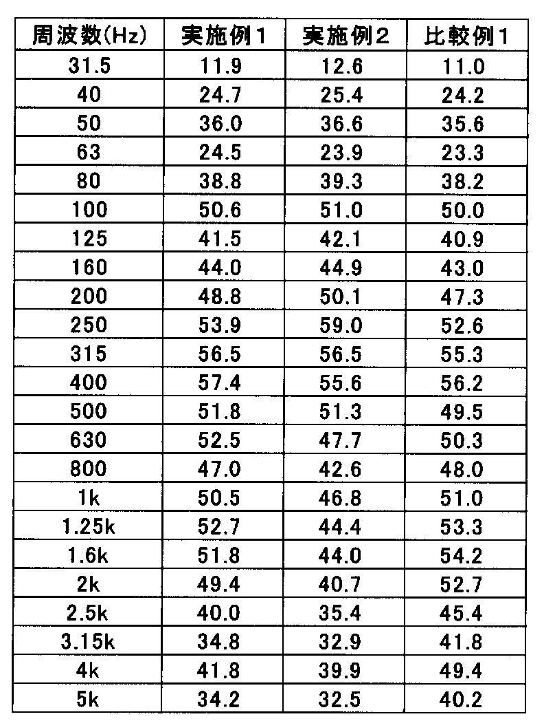
表1および図8より、実施例1および実施例2で得られたテールパイプは、貫通孔が設けられた排気用配管2と筒状の遮熱板3との同軸二重管構造とし、排気用配管2と筒状の遮熱板3との間の一部に吸音性断熱材4が湾曲状に充填されてなるものであることによって、800~5000Hzの高周波数側の領域において、比較例2で用いた単管よりも音圧レベルを低減することができ、人間にとって耳障りな高周波音のみを選択的に低減するとともに、貫通孔が設けられた排気用配管2と筒状の遮熱板3との間の他の部分を湾曲状の閉鎖空間Sとし、該閉鎖空間Sを形成する排気用配管と筒状の遮熱板との距離を所定距離に制御することによって、比較例2で用いた単管よりも100~200Hzの低周波側の領域において音圧レベルを向上させることができ、ユーザーの嗜好性の高いアイドリング時に発生する低周波音の音量を選択的に強調させることができることが分かる。
From Table 1 and FIG. 8, the tail pipe obtained in Example 1 and Example 2 has a coaxial double pipe structure of an exhaust pipe 2 provided with a through hole and a cylindrical heat shield plate 3, and the exhaust pipe is exhausted. In the region of 800 to 5000 Hz on the high frequency side, a comparative example is obtained by partially filling the sound absorbing heat insulating material 4 in a curved shape between the pipe 2 and the tubular heat shield plate 3. The sound pressure level can be reduced as compared with the single pipe used in 2 and only the high-frequency sound that is annoying to humans is selectively reduced, and the exhaust pipe 2 provided with a through hole and the cylindrical heat shield plate In the comparative example 2, the other part between the three and the third is a curved closed space S, and the distance between the exhaust pipe forming the closed space S and the cylindrical heat shield is controlled to a predetermined distance. The sound pressure level in the low frequency region of 100 to 200 Hz from the single tube used Can be above, it can be seen that the volume of low-frequency noise generated at the time of high user preference idling can be selectively emphasized.
(参考例1)
実施例1において、吸音性断熱材4を用いなかったことを除けば、実施例1と同様にしてマフラーカッターを作製し、次いで実施例1と同様にしてテールパイプを作製した。
得られたテールパイプにおいて、実施例1と同様にして音圧変化を評価した。結果を表2および図9に示す。
なお、表2および図9においては、比較のために、比較例1の結果も併記した。 (Reference Example 1)
A muffler cutter was produced in the same manner as in Example 1 except that the sound-absorbingheat insulating material 4 was not used in Example 1, and then a tail pipe was produced in the same manner as in Example 1.
In the obtained tail pipe, the change in sound pressure was evaluated in the same manner as in Example 1. The results are shown in Table 2 and FIG.
In Table 2 and FIG. 9, the results of Comparative Example 1 are also shown for comparison.
実施例1において、吸音性断熱材4を用いなかったことを除けば、実施例1と同様にしてマフラーカッターを作製し、次いで実施例1と同様にしてテールパイプを作製した。
得られたテールパイプにおいて、実施例1と同様にして音圧変化を評価した。結果を表2および図9に示す。
なお、表2および図9においては、比較のために、比較例1の結果も併記した。 (Reference Example 1)
A muffler cutter was produced in the same manner as in Example 1 except that the sound-absorbing
In the obtained tail pipe, the change in sound pressure was evaluated in the same manner as in Example 1. The results are shown in Table 2 and FIG.
In Table 2 and FIG. 9, the results of Comparative Example 1 are also shown for comparison.
(参考例2)
実施例1において、吸音性断熱材4を用いず、さらに排気用配管2として用いたSUS管の、長手方向の側壁全体に設けられた複数の開口部をアルミニウムテープ(スリオンテック社製 耐熱アルミテープ)で塞いだことを除けば、実施例1と同様にしてマフラーカッターを作製し、次いで実施例1と同様にしてテールパイプを作製した。
得られたテールパイプにおいて、実施例1と同様にして音圧変化を評価した。結果を表2および図9に示す。 (Reference Example 2)
In Example 1, the sound absorbingheat insulating material 4 is not used, and the plurality of openings provided in the entire side wall in the longitudinal direction of the SUS pipe used as the exhaust pipe 2 are made of aluminum tape (heat-resistant aluminum tape manufactured by Sliontec). A muffler cutter was produced in the same manner as in Example 1 except that the tail pipe was closed, and then a tail pipe was produced in the same manner as in Example 1.
In the obtained tail pipe, the change in sound pressure was evaluated in the same manner as in Example 1. The results are shown in Table 2 and FIG.
実施例1において、吸音性断熱材4を用いず、さらに排気用配管2として用いたSUS管の、長手方向の側壁全体に設けられた複数の開口部をアルミニウムテープ(スリオンテック社製 耐熱アルミテープ)で塞いだことを除けば、実施例1と同様にしてマフラーカッターを作製し、次いで実施例1と同様にしてテールパイプを作製した。
得られたテールパイプにおいて、実施例1と同様にして音圧変化を評価した。結果を表2および図9に示す。 (Reference Example 2)
In Example 1, the sound absorbing
In the obtained tail pipe, the change in sound pressure was evaluated in the same manner as in Example 1. The results are shown in Table 2 and FIG.
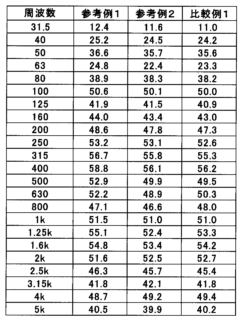
表2および図9の結果より、参考例1で得られたテールパイプは、マフラーカッターとしてパンチング穴を有する排気用配管を用いてなるものであることから、パンチング穴が塞がれた排気用配管を用いたマフラーカッターを有する参考例2のテールパイプや、単管からなる比較例1のテールパイプと比較して、特に100~200Hzの低周波数側の領域において、音圧レベルが上昇傾向にあることが分かる。
From the results of Table 2 and FIG. 9, the tail pipe obtained in Reference Example 1 is an exhaust pipe having a punching hole as a muffler cutter. Compared with the tail pipe of Reference Example 2 having a muffler cutter using a single pipe and the tail pipe of Comparative Example 1 consisting of a single pipe, the sound pressure level tends to increase, particularly in the low frequency region of 100 to 200 Hz. I understand that. *
(参考例3)
図10は、本参考例で作製したマフラーカッターの説明図であり、図10(a)は、排気用配管2の正面図(左図)および該正面図のd-d'線垂直断面図(右図)を示すものであり、図10(b)は、筒状の遮熱板3の正面図(左図)および該正面図のe-e'線垂直断面図(右図)を示すものであり、図10(c)は、図10(a)に示す排気用配管2に図10(b)に示す筒状の遮熱板3を同軸状に固定したマフラーカッターの正面図(左図)および該正面図のf-f’線垂直断面図(右図)を示すものであり、図10(d)は、図10(c)に示すマフラーカッターの長手方向に沿う垂直断面図を示すものである。
本参考例においては、図10(a)に示すように、SUS製単管(外径54mm、板厚0.4mm、長さ340mm、熱伝導率27W/(m・K)(400℃))の片側端部において、長手方向の側壁全体に複数の円形貫通孔(直径3mm)を5mm間隔で576個設けることにより、上記単管の片側端部に、パンチングメタル状の排気用配管2を形成した。
図10(b)に示すように、筒上の遮熱板3として、締付け固定用の耳部Mを有するSUS管(外径72mm、板厚1.0mm、熱伝導率27W/(m・K)(400℃)、2~15μmの波長における放射率0.3)を用意すると共に、アルミニウム製のリング状スペーサー(外径70mm、内径54mm、厚さ10mm)を2個用意して、図10(c)および図10(d)に示すように、排気用配管2の外表面にリング状のスペーサーsを介して筒状の遮熱板3を配置した上で、遮熱板3に設けられた耳部Mに設けられたボルト穴にボルトを通して締付け固定することにより、テールパイプTの端部に排気用配管2と筒状の遮熱板3とを8mmの距離で離間させつつ固定したマフラーカッター1を作製した。 (Reference Example 3)
FIG. 10 is an explanatory view of the muffler cutter produced in this reference example. FIG. 10 (a) is a front view of the exhaust pipe 2 (left figure) and a vertical sectional view taken along the line dd ′ of the front view (FIG. 10). FIG. 10 (b) shows a front view (left view) of thetubular heat shield 3 and a vertical sectional view (right view) taken along the line ee ′ of the front view. FIG. 10C is a front view of the muffler cutter in which the tubular heat shield plate 3 shown in FIG. 10B is coaxially fixed to the exhaust pipe 2 shown in FIG. ) And a front sectional view taken along line ff ′ (right diagram), FIG. 10 (d) shows a vertical sectional view along the longitudinal direction of the muffler cutter shown in FIG. 10 (c). Is.
In this reference example, as shown in FIG. 10 (a), a SUS single tube (outer diameter 54 mm, plate thickness 0.4 mm, length 340 mm, thermal conductivity 27 W / (m · K) (400 ° C.)) A punching metal-like exhaust pipe 2 is formed at one end of the single pipe by providing 576 circular through holes (diameter 3 mm) at intervals of 5 mm on the entire side wall in the longitudinal direction. did.
As shown in FIG. 10 (b), as theheat shield plate 3 on the cylinder, an SUS tube (outer diameter 72 mm, plate thickness 1.0 mm, thermal conductivity 27 W / (m · K) having a fastening fixing ear M. ) (400 ° C.) emissivity 0.3 at a wavelength of 2 to 15 μm) and two aluminum ring spacers (outer diameter 70 mm, inner diameter 54 mm, thickness 10 mm) were prepared. As shown in FIG. 10 (c) and FIG. 10 (d), a tubular heat shield plate 3 is arranged on the outer surface of the exhaust pipe 2 via a ring-shaped spacer s, and then provided on the heat shield plate 3. A muffler in which the exhaust pipe 2 and the tubular heat shield 3 are fixed to the end of the tail pipe T while being separated from each other by a distance of 8 mm by tightening and fixing the bolts in the bolt holes provided in the ears M. Cutter 1 was produced.
図10は、本参考例で作製したマフラーカッターの説明図であり、図10(a)は、排気用配管2の正面図(左図)および該正面図のd-d'線垂直断面図(右図)を示すものであり、図10(b)は、筒状の遮熱板3の正面図(左図)および該正面図のe-e'線垂直断面図(右図)を示すものであり、図10(c)は、図10(a)に示す排気用配管2に図10(b)に示す筒状の遮熱板3を同軸状に固定したマフラーカッターの正面図(左図)および該正面図のf-f’線垂直断面図(右図)を示すものであり、図10(d)は、図10(c)に示すマフラーカッターの長手方向に沿う垂直断面図を示すものである。
本参考例においては、図10(a)に示すように、SUS製単管(外径54mm、板厚0.4mm、長さ340mm、熱伝導率27W/(m・K)(400℃))の片側端部において、長手方向の側壁全体に複数の円形貫通孔(直径3mm)を5mm間隔で576個設けることにより、上記単管の片側端部に、パンチングメタル状の排気用配管2を形成した。
図10(b)に示すように、筒上の遮熱板3として、締付け固定用の耳部Mを有するSUS管(外径72mm、板厚1.0mm、熱伝導率27W/(m・K)(400℃)、2~15μmの波長における放射率0.3)を用意すると共に、アルミニウム製のリング状スペーサー(外径70mm、内径54mm、厚さ10mm)を2個用意して、図10(c)および図10(d)に示すように、排気用配管2の外表面にリング状のスペーサーsを介して筒状の遮熱板3を配置した上で、遮熱板3に設けられた耳部Mに設けられたボルト穴にボルトを通して締付け固定することにより、テールパイプTの端部に排気用配管2と筒状の遮熱板3とを8mmの距離で離間させつつ固定したマフラーカッター1を作製した。 (Reference Example 3)
FIG. 10 is an explanatory view of the muffler cutter produced in this reference example. FIG. 10 (a) is a front view of the exhaust pipe 2 (left figure) and a vertical sectional view taken along the line dd ′ of the front view (FIG. 10). FIG. 10 (b) shows a front view (left view) of the
In this reference example, as shown in FIG. 10 (a), a SUS single tube (outer diameter 54 mm, plate thickness 0.4 mm, length 340 mm, thermal conductivity 27 W / (m · K) (400 ° C.)) A punching metal-
As shown in FIG. 10 (b), as the
(音圧変化評価)
図7に示すように、スピーカーSのスピーカーコーン上に、テールパイプ本体が下部マフラーカッター1が上部に位置するようにテールパイプTを直立配置した状態で、1/3オクターブバンド周波数でホワイトノイズを生じさせ、マフラーカッターから500mm離れた位置に配置したマイクMにより音圧レベル(dB)の変化を測定した。結果を表3および図11に示す。 (Sound pressure change evaluation)
As shown in FIG. 7, with the tail pipe T placed upright on the speaker cone of the speaker S so that the lowerpipe muffler cutter 1 is located on the upper part of the tail pipe body, white noise is generated at 1/3 octave band frequency. The change of the sound pressure level (dB) was measured by the microphone M that was generated and placed at a position 500 mm away from the muffler cutter. The results are shown in Table 3 and FIG.
図7に示すように、スピーカーSのスピーカーコーン上に、テールパイプ本体が下部マフラーカッター1が上部に位置するようにテールパイプTを直立配置した状態で、1/3オクターブバンド周波数でホワイトノイズを生じさせ、マフラーカッターから500mm離れた位置に配置したマイクMにより音圧レベル(dB)の変化を測定した。結果を表3および図11に示す。 (Sound pressure change evaluation)
As shown in FIG. 7, with the tail pipe T placed upright on the speaker cone of the speaker S so that the lower
(参考例4)
参考例3において、筒状の遮熱板3として、外径72mmの遮熱板に代えて、締付け固定用の耳部Mを有するSUS管(外径88mm、板厚1.0mm、熱伝導率27W/(m・K)(400℃)、2~15μmの波長における放射率0.3)を用意すると共に、アルミニウム製のリング状スペーサー(外径86mm、内径54mm、厚さ10mm)を2個用意して、図10(c)および図10(d)に示すように、排気用配管2の外表面にリング状のスペーサーsを介して筒状の遮熱板3を配置した上で、遮熱板3に設けられた耳部Mに設けられたボルト穴にボルトを通して締付け固定することにより、テールパイプTの端部に排気用配管2と筒状の遮熱板3とを16mmの距離で離間させつつ固定したマフラーカッター1を作製した。
得られたテールパイプTにおいて、参考例3と同様にして音圧変化を評価した。結果を表3および図11に示す。 (Reference Example 4)
In Reference Example 3, instead of the heat shield plate having an outer diameter of 72 mm as the tubularheat shield plate 3, a SUS tube having an ear portion M for fastening and fixing (outer diameter of 88 mm, plate thickness of 1.0 mm, thermal conductivity) 27 W / (m · K) (400 ° C), emissivity 0.3 at a wavelength of 2 to 15 μm, and two aluminum ring spacers (outer diameter 86 mm, inner diameter 54 mm, thickness 10 mm) As shown in FIGS. 10 (c) and 10 (d), a tubular heat shield 3 is disposed on the outer surface of the exhaust pipe 2 via a ring-shaped spacer s, and then the shield. The exhaust pipe 2 and the tubular heat shield plate 3 are connected to the end of the tail pipe T at a distance of 16 mm by tightening and fixing the bolts in the bolt holes provided in the ear M provided in the hot plate 3. A muffler cutter 1 fixed while being separated was produced.
In the obtained tail pipe T, the sound pressure change was evaluated in the same manner as in Reference Example 3. The results are shown in Table 3 and FIG.
参考例3において、筒状の遮熱板3として、外径72mmの遮熱板に代えて、締付け固定用の耳部Mを有するSUS管(外径88mm、板厚1.0mm、熱伝導率27W/(m・K)(400℃)、2~15μmの波長における放射率0.3)を用意すると共に、アルミニウム製のリング状スペーサー(外径86mm、内径54mm、厚さ10mm)を2個用意して、図10(c)および図10(d)に示すように、排気用配管2の外表面にリング状のスペーサーsを介して筒状の遮熱板3を配置した上で、遮熱板3に設けられた耳部Mに設けられたボルト穴にボルトを通して締付け固定することにより、テールパイプTの端部に排気用配管2と筒状の遮熱板3とを16mmの距離で離間させつつ固定したマフラーカッター1を作製した。
得られたテールパイプTにおいて、参考例3と同様にして音圧変化を評価した。結果を表3および図11に示す。 (Reference Example 4)
In Reference Example 3, instead of the heat shield plate having an outer diameter of 72 mm as the tubular
In the obtained tail pipe T, the sound pressure change was evaluated in the same manner as in Reference Example 3. The results are shown in Table 3 and FIG.
(参考例5)
参考例1において、筒状の遮熱板3として、外径72mmの遮熱板に代えて、締付け固定用の耳部Mを有するSUS管(外径146mm、板厚1.0mm、熱伝導率27W/(m・K)(400℃)、2~15μmの波長における放射率0.3)を用意すると共に、アルミニウム製のリング状スペーサー(外径144mm、内径54mm、厚さ10mm)を2個用意して、図10(c)および図10(d)に示すように、排気用配管2の外表面にリング状のスペーサーsを介して筒状の遮熱板3を配置した上で、遮熱板3に設けられた耳部Mに設けられたボルト穴にボルトを通して締付け固定することにより、テールパイプTの端部に排気用配管2と筒状の遮熱板3とを45mmの距離で離間させつつ固定したマフラーカッター1を作製した。
得られたテールパイプTにおいて、参考例3と同様にして音圧変化を評価した。結果を表3および図11に示す。 (Reference Example 5)
In Reference Example 1, instead of the heat shield plate having an outer diameter of 72 mm as the tubularheat shield plate 3, a SUS tube having an ear M for fastening and fixing (outer diameter 146 mm, plate thickness 1.0 mm, thermal conductivity 27 W / (m · K) (400 ° C), emissivity 0.3 at a wavelength of 2 to 15 μm, and two aluminum ring spacers (outer diameter 144 mm, inner diameter 54 mm, thickness 10 mm) As shown in FIGS. 10 (c) and 10 (d), a tubular heat shield 3 is disposed on the outer surface of the exhaust pipe 2 via a ring-shaped spacer s, and then the shield. The exhaust pipe 2 and the cylindrical heat shield plate 3 are connected to the end of the tail pipe T at a distance of 45 mm by tightening and fixing the bolts in the bolt holes provided in the ears M provided in the hot plate 3. A muffler cutter 1 fixed while being separated was produced.
In the obtained tail pipe T, the sound pressure change was evaluated in the same manner as in Reference Example 3. The results are shown in Table 3 and FIG.
参考例1において、筒状の遮熱板3として、外径72mmの遮熱板に代えて、締付け固定用の耳部Mを有するSUS管(外径146mm、板厚1.0mm、熱伝導率27W/(m・K)(400℃)、2~15μmの波長における放射率0.3)を用意すると共に、アルミニウム製のリング状スペーサー(外径144mm、内径54mm、厚さ10mm)を2個用意して、図10(c)および図10(d)に示すように、排気用配管2の外表面にリング状のスペーサーsを介して筒状の遮熱板3を配置した上で、遮熱板3に設けられた耳部Mに設けられたボルト穴にボルトを通して締付け固定することにより、テールパイプTの端部に排気用配管2と筒状の遮熱板3とを45mmの距離で離間させつつ固定したマフラーカッター1を作製した。
得られたテールパイプTにおいて、参考例3と同様にして音圧変化を評価した。結果を表3および図11に示す。 (Reference Example 5)
In Reference Example 1, instead of the heat shield plate having an outer diameter of 72 mm as the tubular
In the obtained tail pipe T, the sound pressure change was evaluated in the same manner as in Reference Example 3. The results are shown in Table 3 and FIG.
(比較例2)
テールパイプTに代えてSUS製単管(外径54mm、板厚0.4mm、長さ340mm、熱伝導率27W/(m・K)(400℃))を用いた以外は、参考例1と同様にして音圧変化を評価した。結果を表3および図11に示す。 (Comparative Example 2)
Reference Example 1 except that a SUS single pipe (outer diameter 54 mm, plate thickness 0.4 mm, length 340 mm, thermal conductivity 27 W / (m · K) (400 ° C.)) was used instead of the tail pipe T Similarly, changes in sound pressure were evaluated. The results are shown in Table 3 and FIG.
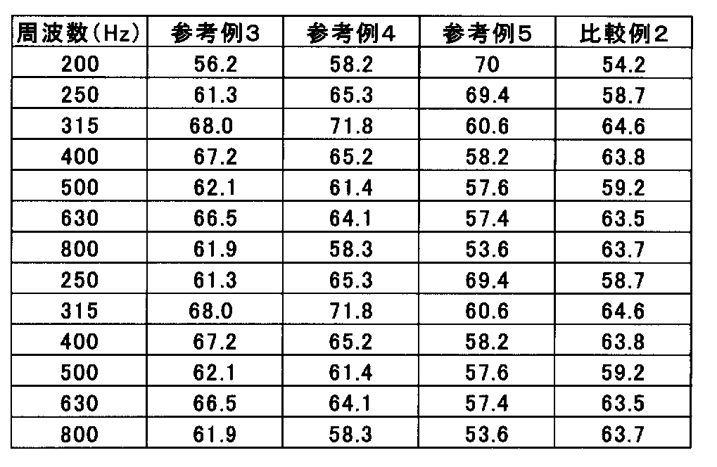
表3および図11より、参考例3~参考例5で得られたテールパイプは、貫通孔を設けた排気用配管2と筒状の遮熱板3との同軸二重管構造としてなるものであることによって、800Hzの高周波領域において、比較例2で用いた単管よりも音圧レベルを低減することができ、人間にとって耳障りな高周波音のみを選択的に低減するとともに、排気用配管2と筒状の遮熱板3との間に湾曲状の閉鎖空間を設け、該閉鎖空間を形成する排気用配管と筒状の遮熱板との距離を所定距離に制御することによって、比較例2で用いた単管よりも200Hzの低周波領域において音圧レベルを向上させることができ、ユーザーの嗜好性の高いアイドリング時に発生する低周波音の音量を選択的に強調させることができることが分かる。
From Table 3 and FIG. 11, the tail pipes obtained in Reference Example 3 to Reference Example 5 have a coaxial double pipe structure of an exhaust pipe 2 provided with a through hole and a cylindrical heat shield plate 3. As a result, in the high frequency region of 800 Hz, the sound pressure level can be reduced as compared with the single tube used in Comparative Example 2, and only the high frequency sound that is annoying to humans is selectively reduced, and the exhaust pipe 2 and Comparative Example 2 by providing a curved closed space between the tubular heat shield plate 3 and controlling the distance between the exhaust pipe forming the closed space and the tubular heat shield plate to a predetermined distance. It can be seen that the sound pressure level can be improved in the low frequency region of 200 Hz as compared with the single tube used in the above, and the volume of the low frequency sound generated during idling with high user preference can be selectively emphasized.
(参考例6)
参考例5において、SUS製単管(外径54mm、板厚1.0mm、長さ340mm、熱伝導率27W/(m・K)(400℃))に円形貫通孔を設けなかったことを除けば、参考例5と同様にして、テールパイプTの端部に排気用配管2と筒状の遮熱板3とを45mmの距離で離間させつつ固定したマフラーカッター1を作製した。
得られたテールパイプTにおいて、参考例3と同様にして音圧変化を評価した。結果を表4および図13に示す。
なお、表4および図13においては、比較のために、参考例5および比較例2の結果も併記した。 (Reference Example 6)
In Reference Example 5, except that a SUS single tube (outer diameter 54 mm, plate thickness 1.0 mm, length 340 mm, thermal conductivity 27 W / (m · K) (400 ° C.)) was not provided with a circular through hole. For example, in the same manner as in Reference Example 5, amuffler cutter 1 in which the exhaust pipe 2 and the tubular heat shield 3 were fixed to the end of the tail pipe T while being separated by a distance of 45 mm was produced.
In the obtained tail pipe T, the sound pressure change was evaluated in the same manner as in Reference Example 3. The results are shown in Table 4 and FIG.
In Table 4 and FIG. 13, the results of Reference Example 5 and Comparative Example 2 are also shown for comparison.
参考例5において、SUS製単管(外径54mm、板厚1.0mm、長さ340mm、熱伝導率27W/(m・K)(400℃))に円形貫通孔を設けなかったことを除けば、参考例5と同様にして、テールパイプTの端部に排気用配管2と筒状の遮熱板3とを45mmの距離で離間させつつ固定したマフラーカッター1を作製した。
得られたテールパイプTにおいて、参考例3と同様にして音圧変化を評価した。結果を表4および図13に示す。
なお、表4および図13においては、比較のために、参考例5および比較例2の結果も併記した。 (Reference Example 6)
In Reference Example 5, except that a SUS single tube (outer diameter 54 mm, plate thickness 1.0 mm, length 340 mm, thermal conductivity 27 W / (m · K) (400 ° C.)) was not provided with a circular through hole. For example, in the same manner as in Reference Example 5, a
In the obtained tail pipe T, the sound pressure change was evaluated in the same manner as in Reference Example 3. The results are shown in Table 4 and FIG.
In Table 4 and FIG. 13, the results of Reference Example 5 and Comparative Example 2 are also shown for comparison.
(参考例7)
参考例5において、SUS製単管(外径54mm、板厚1.0mm、長さ340mm、熱伝導率27W/(m・K)(400℃))の片側端部において、図12(a)に示すように、排気用配管2の上流側(排気ガスが流入する側)の側壁全体に円形貫通孔(直径3mm)を5mm間隔で288個設けたものを用いたことを除けば、参考例5と同様にして、テールパイプTの端部に排気用配管2と筒状の遮熱板3とを45mmの距離で離間させつつ固定したマフラーカッター1を作製した。
得られたテールパイプTにおいて、参考例3と同様にして音圧変化を評価した。結果を表4および図13に示す。 (Reference Example 7)
In Reference Example 5, at one end of a SUS single tube (outer diameter 54 mm, plate thickness 1.0 mm, length 340 mm, thermal conductivity 27 W / (m · K) (400 ° C.)), FIG. As shown in Fig. 5, the reference example is used except that 288 circular through holes (diameter 3 mm) are provided at intervals of 5 mm on the entire side wall on the upstream side (exhaust gas inflow side) of the exhaust pipe 2. 5, a muffler cutter 1 in which the exhaust pipe 2 and the cylindrical heat shield 3 were fixed to the end of the tail pipe T while being separated by a distance of 45 mm was produced.
In the obtained tail pipe T, the sound pressure change was evaluated in the same manner as in Reference Example 3. The results are shown in Table 4 and FIG.
参考例5において、SUS製単管(外径54mm、板厚1.0mm、長さ340mm、熱伝導率27W/(m・K)(400℃))の片側端部において、図12(a)に示すように、排気用配管2の上流側(排気ガスが流入する側)の側壁全体に円形貫通孔(直径3mm)を5mm間隔で288個設けたものを用いたことを除けば、参考例5と同様にして、テールパイプTの端部に排気用配管2と筒状の遮熱板3とを45mmの距離で離間させつつ固定したマフラーカッター1を作製した。
得られたテールパイプTにおいて、参考例3と同様にして音圧変化を評価した。結果を表4および図13に示す。 (Reference Example 7)
In Reference Example 5, at one end of a SUS single tube (outer diameter 54 mm, plate thickness 1.0 mm, length 340 mm, thermal conductivity 27 W / (m · K) (400 ° C.)), FIG. As shown in Fig. 5, the reference example is used except that 288 circular through holes (
In the obtained tail pipe T, the sound pressure change was evaluated in the same manner as in Reference Example 3. The results are shown in Table 4 and FIG.
(参考例8)
参考例5において、SUS製単管(外径54mm、板厚1.0mm、長さ340mm、熱伝導率27W/(m・K)(400℃))の片側端部において、図12(b)に示すように、排気用配管2の下流側(排気ガスが流出する側)の側壁全体に円形貫通孔(直径3mm)を5mm間隔で288個設けたものを用いたことを除けば、参考例5と同様にして、テールパイプTの端部に排気用配管2と筒状の遮熱板3とを45mmの距離で離間させつつ固定したマフラーカッター1を作製した。
得られたテールパイプTにおいて、参考例3と同様にして音圧変化を評価した。結果を表4および図13に示す。 (Reference Example 8)
In Reference Example 5, at one end of a SUS single tube (outer diameter 54 mm, plate thickness 1.0 mm, length 340 mm, thermal conductivity 27 W / (m · K) (400 ° C.)), FIG. As shown in FIG. 5, the reference example is used except that 288 circular through holes (diameter 3 mm) are provided at intervals of 5 mm on the entire downstream side wall of the exhaust pipe 2 (exhaust gas outflow side). 5, a muffler cutter 1 in which the exhaust pipe 2 and the cylindrical heat shield 3 were fixed to the end of the tail pipe T while being separated by a distance of 45 mm was produced.
In the obtained tail pipe T, the sound pressure change was evaluated in the same manner as in Reference Example 3. The results are shown in Table 4 and FIG.
参考例5において、SUS製単管(外径54mm、板厚1.0mm、長さ340mm、熱伝導率27W/(m・K)(400℃))の片側端部において、図12(b)に示すように、排気用配管2の下流側(排気ガスが流出する側)の側壁全体に円形貫通孔(直径3mm)を5mm間隔で288個設けたものを用いたことを除けば、参考例5と同様にして、テールパイプTの端部に排気用配管2と筒状の遮熱板3とを45mmの距離で離間させつつ固定したマフラーカッター1を作製した。
得られたテールパイプTにおいて、参考例3と同様にして音圧変化を評価した。結果を表4および図13に示す。 (Reference Example 8)
In Reference Example 5, at one end of a SUS single tube (outer diameter 54 mm, plate thickness 1.0 mm, length 340 mm, thermal conductivity 27 W / (m · K) (400 ° C.)), FIG. As shown in FIG. 5, the reference example is used except that 288 circular through holes (
In the obtained tail pipe T, the sound pressure change was evaluated in the same manner as in Reference Example 3. The results are shown in Table 4 and FIG.
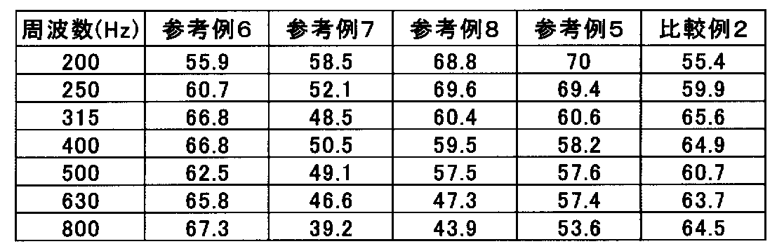
表4および図11より、参考例6で得られたテールパイプは、貫通孔を有さない排気用配管2と筒状の遮熱板3との同軸二重管構造としてなるものであることによって、比較例2で使用した単管よりも測定周波数全域において音圧レベルを向上させることができることが分かる。
また、参考例5、参考例7および参考例8で得られたテールパイプは、貫通孔を設けた排気用配管2と筒状の遮熱板との同軸二重管構造としつつ、排気用配管2と筒状の遮熱板3との間に形成された排気用配管と筒状の遮熱板との距離を所定距離に制御することによって、800Hzの高周波領域において、比較例2や参考例6よりも音圧レベルを低減することができ、人間にとって耳障りな高周波音のみを選択的に低減するとともに、比較例2や参考例6よりも200Hzの低周波領域において音圧レベルを向上させることができ、ユーザーの嗜好性の高いアイドリング時に発生する低周波音の音量を選択的に強調させることができることが分かる。
さらに、参考例7で得られたテールパイプと参考例8で得られたテールパイプとを比較すると、参考例7で得られたテールパイプは参考例8で得られたテールパイプに比較して、全体的に音圧レベルが低下していることが分かる。これは、参考例7で得られたテールパイプにおいては、貫通孔が設けられた位置が排気用配管2の上流側(排気ガスが流入する側)であることから、排気用配管2の下流側に貫通孔が設けられた参考例8で得られたテールパイプに比較して、排気音の干渉が生じ易い為であると考えられる。 From Table 4 and FIG. 11, the tail pipe obtained in Reference Example 6 has a coaxial double pipe structure of theexhaust pipe 2 having no through hole and the cylindrical heat shield plate 3. It can be seen that the sound pressure level can be improved over the entire measurement frequency than the single tube used in Comparative Example 2.
Further, the tail pipes obtained in Reference Example 5, Reference Example 7 and Reference Example 8 are exhaust pipes having a coaxial double pipe structure of anexhaust pipe 2 having a through hole and a cylindrical heat shield. Comparative Example 2 and Reference Example in the high frequency region of 800 Hz by controlling the distance between the exhaust pipe formed between the tube 2 and the tubular heat shield plate 3 and the tubular heat shield plate to a predetermined distance. The sound pressure level can be reduced more than 6 and only high-frequency sound that is harsh to human beings can be selectively reduced, and the sound pressure level can be improved in the low frequency region of 200 Hz than Comparative Example 2 and Reference Example 6. It can be seen that the volume of low frequency sound generated during idling with high user preference can be selectively emphasized.
Furthermore, when comparing the tail pipe obtained in Reference Example 7 and the tail pipe obtained in Reference Example 8, the tail pipe obtained in Reference Example 7 is compared with the tail pipe obtained in Reference Example 8, It can be seen that the sound pressure level is lowered overall. This is because in the tail pipe obtained in Reference Example 7, the position where the through hole is provided is the upstream side of the exhaust pipe 2 (the side into which the exhaust gas flows), and therefore the downstream side of theexhaust pipe 2 It is considered that this is because the interference of the exhaust sound is more likely to occur as compared with the tail pipe obtained in Reference Example 8 in which the through hole is provided.
また、参考例5、参考例7および参考例8で得られたテールパイプは、貫通孔を設けた排気用配管2と筒状の遮熱板との同軸二重管構造としつつ、排気用配管2と筒状の遮熱板3との間に形成された排気用配管と筒状の遮熱板との距離を所定距離に制御することによって、800Hzの高周波領域において、比較例2や参考例6よりも音圧レベルを低減することができ、人間にとって耳障りな高周波音のみを選択的に低減するとともに、比較例2や参考例6よりも200Hzの低周波領域において音圧レベルを向上させることができ、ユーザーの嗜好性の高いアイドリング時に発生する低周波音の音量を選択的に強調させることができることが分かる。
さらに、参考例7で得られたテールパイプと参考例8で得られたテールパイプとを比較すると、参考例7で得られたテールパイプは参考例8で得られたテールパイプに比較して、全体的に音圧レベルが低下していることが分かる。これは、参考例7で得られたテールパイプにおいては、貫通孔が設けられた位置が排気用配管2の上流側(排気ガスが流入する側)であることから、排気用配管2の下流側に貫通孔が設けられた参考例8で得られたテールパイプに比較して、排気音の干渉が生じ易い為であると考えられる。 From Table 4 and FIG. 11, the tail pipe obtained in Reference Example 6 has a coaxial double pipe structure of the
Further, the tail pipes obtained in Reference Example 5, Reference Example 7 and Reference Example 8 are exhaust pipes having a coaxial double pipe structure of an
Furthermore, when comparing the tail pipe obtained in Reference Example 7 and the tail pipe obtained in Reference Example 8, the tail pipe obtained in Reference Example 7 is compared with the tail pipe obtained in Reference Example 8, It can be seen that the sound pressure level is lowered overall. This is because in the tail pipe obtained in Reference Example 7, the position where the through hole is provided is the upstream side of the exhaust pipe 2 (the side into which the exhaust gas flows), and therefore the downstream side of the
(断熱性試験)
実施例1で得られたマフラーカッター1の内部にヒータを設置して出力440Wで90分間放熱したときに、吸音性断熱材4を充填した側(上部遮熱板3a側)の外部にポリイミド製バンパーを設置し、マフラーカッター1とバンパーとの距離を12mm~29mmに変更した場合のバンパーの表面温度を測定した。結果を表5に示す。
また、吸音性断熱材4を充填しなかった以外は実施例1と同様にして作製したマフラーカッター(以下、「中空二重管」と称する)と、吸音性断熱材4を排気用配管2と筒状の遮熱板との間に形成される空間全体に充填したマフラーカッター(以下、「フル充填二重管」と称する)についても、上記と同様の方法でバンパーの表面温度を測定した。結果を表5に示す。 (Insulation test)
When a heater is installed inside themuffler cutter 1 obtained in Example 1 and radiates heat for 90 minutes at an output of 440 W, it is made of polyimide outside the side (upper heat shield 3 a side) filled with the sound-absorbing heat insulating material 4. A bumper was installed, and the surface temperature of the bumper was measured when the distance between the muffler cutter 1 and the bumper was changed to 12 mm to 29 mm. The results are shown in Table 5.
Further, a muffler cutter (hereinafter referred to as “hollow double pipe”) manufactured in the same manner as in Example 1 except that the sound-absorbingheat insulating material 4 was not filled, and the sound-absorbing heat insulating material 4 were connected to the exhaust pipe 2. The surface temperature of the bumper was also measured in the same manner as described above for a muffler cutter (hereinafter referred to as “full-filled double pipe”) filled in the entire space formed between the cylindrical heat shield plates. The results are shown in Table 5.
実施例1で得られたマフラーカッター1の内部にヒータを設置して出力440Wで90分間放熱したときに、吸音性断熱材4を充填した側(上部遮熱板3a側)の外部にポリイミド製バンパーを設置し、マフラーカッター1とバンパーとの距離を12mm~29mmに変更した場合のバンパーの表面温度を測定した。結果を表5に示す。
また、吸音性断熱材4を充填しなかった以外は実施例1と同様にして作製したマフラーカッター(以下、「中空二重管」と称する)と、吸音性断熱材4を排気用配管2と筒状の遮熱板との間に形成される空間全体に充填したマフラーカッター(以下、「フル充填二重管」と称する)についても、上記と同様の方法でバンパーの表面温度を測定した。結果を表5に示す。 (Insulation test)
When a heater is installed inside the
Further, a muffler cutter (hereinafter referred to as “hollow double pipe”) manufactured in the same manner as in Example 1 except that the sound-absorbing
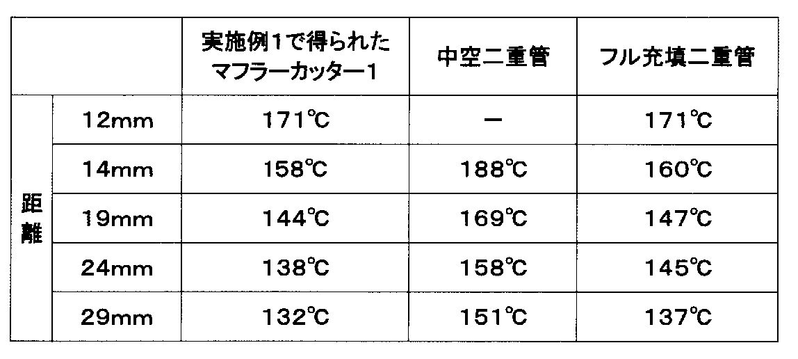
表5より、実施例1で得られたマフラーカッター1は、吸音性断熱材が充填されていない中空二重管に比較してバンパー表面の温度上昇を十分に低減し得るものであることが分かる。
また、表5より、実施例1で得られたマフラーカッター1は、排気用配管と筒状の遮熱板との間の一部にのみ吸音性断熱材を充填してなるものであるにも拘わらず、排気用配管と筒状の遮熱板との間に形成される空間全体に吸音性断熱材を充填したマフラーカッター(フル充填二重管)と同等以上にバンパー側への放熱を抑制し、バンパー表面の温度上昇を低減し得るものであることが分かる。 From Table 5, it can be seen that themuffler cutter 1 obtained in Example 1 can sufficiently reduce the temperature rise of the bumper surface as compared with a hollow double tube not filled with a sound absorbing heat insulating material. .
Moreover, from Table 5, themuffler cutter 1 obtained in Example 1 is formed by filling a sound-absorbing heat insulating material only in a part between the exhaust pipe and the tubular heat shield. Regardless, the heat radiation to the bumper side is suppressed to the same level or more as a muffler cutter (full-filled double pipe) in which the entire space formed between the exhaust pipe and the cylindrical heat shield is filled with sound-absorbing heat insulating material. And it turns out that the temperature rise of a bumper surface can be reduced.
また、表5より、実施例1で得られたマフラーカッター1は、排気用配管と筒状の遮熱板との間の一部にのみ吸音性断熱材を充填してなるものであるにも拘わらず、排気用配管と筒状の遮熱板との間に形成される空間全体に吸音性断熱材を充填したマフラーカッター(フル充填二重管)と同等以上にバンパー側への放熱を抑制し、バンパー表面の温度上昇を低減し得るものであることが分かる。 From Table 5, it can be seen that the
Moreover, from Table 5, the
本発明によれば、断熱性および消音性に優れるとともに排気音の音質を向上し得るマフラーカッターを提供することができる。また、本発明によれば、上記マフラーカッターを端部に装着してなるテールパイプを提供することができる。
According to the present invention, it is possible to provide a muffler cutter that is excellent in heat insulation and noise reduction and can improve the sound quality of exhaust sound. Moreover, according to this invention, the tail pipe formed by mounting | wearing the said muffler cutter to an edge part can be provided.
1 マフラーカッター
2 排気用配管
3 筒状の遮熱板
3a 上部遮熱板
3b 下部遮熱板
3c 端部
4 吸音性断熱材
5 車輌本体
6 フーリエ変換赤外分光光度計
71 入射光
72 反射光または透過光
8 反射鏡
9 回転台
10 サンプル
11 ハロゲンヒータ
12 検出器
13 冷却水
X 高温反射率・透過率測定装置
h ホルダー
S 閉鎖空間
T テールランプ
S スピーカー
M マイク DESCRIPTION OFSYMBOLS 1 Muffler cutter 2 Exhaust pipe 3 Cylindrical heat shield 3a Upper heat shield 3b Lower heat shield 3c End 4 Sound absorbing heat insulating material 5 Vehicle body 6 Fourier transform infrared spectrophotometer 71 Incident light 72 Reflected light or Transmitted light 8 Reflector 9 Turntable 10 Sample 11 Halogen heater 12 Detector 13 Cooling water X High temperature reflectance / transmittance measuring device h Holder S Closed space T Tail lamp S Speaker M Microphone
2 排気用配管
3 筒状の遮熱板
3a 上部遮熱板
3b 下部遮熱板
3c 端部
4 吸音性断熱材
5 車輌本体
6 フーリエ変換赤外分光光度計
71 入射光
72 反射光または透過光
8 反射鏡
9 回転台
10 サンプル
11 ハロゲンヒータ
12 検出器
13 冷却水
X 高温反射率・透過率測定装置
h ホルダー
S 閉鎖空間
T テールランプ
S スピーカー
M マイク DESCRIPTION OF
Claims (7)
- 車輌用排気系のテールパイプに装着されるマフラーカッターであって、
側壁に複数の貫通孔が設けられた排気用配管と、該排気用配管の外側に該排気用配管と同軸状に設けられた筒状の遮熱板と、前記排気用配管と筒状の遮熱板との間に充填された吸音性断熱材とを有し、
前記吸音性断熱材は、前記排気用配管と筒状の遮熱板との間の一部にのみ湾曲状に充填されるとともに、前記排気用配管と筒状の遮熱板との間の他の部分には湾曲状の閉鎖空間が形成されてなり、
前記閉鎖空間を形成する排気用配管と筒状の遮熱板との距離が1~50mmである
ことを特徴とするマフラーカッター。 A muffler cutter attached to the tail pipe of a vehicle exhaust system,
An exhaust pipe having a plurality of through holes in the side wall; a cylindrical heat shield plate provided coaxially with the exhaust pipe on the outside of the exhaust pipe; and the exhaust pipe and the cylindrical shield. A sound-absorbing heat insulating material filled between the heat plate and
The sound-absorbing heat insulating material is filled in a curved shape only in a part between the exhaust pipe and the cylindrical heat shield plate, and other than between the exhaust pipe and the cylindrical heat shield plate. A curved closed space is formed in this part,
A muffler cutter, wherein a distance between the exhaust pipe forming the closed space and the cylindrical heat shield is 1 to 50 mm. - 前記貫通孔が、前記排気用配管の側面のうち少なくとも前記吸音性断熱材に対向する部分に設けられている請求項1に記載のマフラーカッター。 The muffler cutter according to claim 1, wherein the through hole is provided in at least a portion of the side surface of the exhaust pipe facing the sound-absorbing heat insulating material.
- 前記吸音性断熱材が、配設時に車輌本体側に位置する前記排気用配管と筒状の遮熱板との間に湾曲状に充填される請求項1に記載のマフラーカッター。 The muffler cutter according to claim 1, wherein the sound-absorbing heat insulating material is filled in a curved shape between the exhaust pipe located on the vehicle main body side and a cylindrical heat shield when disposed.
- 前記吸音性断熱材が、配設時に車輌本体側に位置する前記排気用配管と筒状の遮熱板との間に湾曲状に充填される請求項2に記載のマフラーカッター。 3. The muffler cutter according to claim 2, wherein the sound-absorbing heat insulating material is filled in a curved shape between the exhaust pipe located on the vehicle main body side and a cylindrical heat shield when disposed.
- 前記閉鎖空間が、中空状になっており、配設時に車輌本体側とは反対側に位置する前記排気用配管と筒状の遮熱板との間に湾曲状に形成されてなる請求項3に記載のマフラーカッター。 The closed space is hollow, and is formed in a curved shape between the exhaust pipe located on the opposite side of the vehicle main body when installed and the cylindrical heat shield. The muffler cutter described in 1.
- 前記閉鎖空間が、中空状になっており、配設時に車輌本体側とは反対側に位置する前記排気用配管と筒状の遮熱板との間に湾曲状に形成されてなる請求項4に記載のマフラーカッター。 5. The closed space is hollow and is formed in a curved shape between the exhaust pipe located on the side opposite to the vehicle body side and a tubular heat shield plate when disposed. The muffler cutter described in 1.
- 前記吸音性断熱材の400℃の温度条件下における熱伝導率が0.01~0.1W/(m・K)である請求項1~請求項6のいずれかに記載のマフラーカッター。 The muffler cutter according to any one of claims 1 to 6, wherein the sound-absorbing heat insulating material has a thermal conductivity of 0.01 to 0.1 W / (m · K) under a temperature condition of 400 ° C.
Priority Applications (2)
| Application Number | Priority Date | Filing Date | Title |
|---|---|---|---|
| US14/784,332 US9810117B2 (en) | 2013-04-15 | 2014-04-09 | Muffler cutter |
| EP14785637.1A EP2987979B1 (en) | 2013-04-15 | 2014-04-09 | Muffler cutter |
Applications Claiming Priority (2)
| Application Number | Priority Date | Filing Date | Title |
|---|---|---|---|
| JP2013-085064 | 2013-04-15 | ||
| JP2013085064A JP6153371B2 (en) | 2013-04-15 | 2013-04-15 | Muffler cutter |
Publications (1)
| Publication Number | Publication Date |
|---|---|
| WO2014171380A1 true WO2014171380A1 (en) | 2014-10-23 |
Family
ID=51731323
Family Applications (1)
| Application Number | Title | Priority Date | Filing Date |
|---|---|---|---|
| PCT/JP2014/060314 WO2014171380A1 (en) | 2013-04-15 | 2014-04-09 | Muffler cutter |
Country Status (4)
| Country | Link |
|---|---|
| US (1) | US9810117B2 (en) |
| EP (1) | EP2987979B1 (en) |
| JP (1) | JP6153371B2 (en) |
| WO (1) | WO2014171380A1 (en) |
Cited By (2)
| Publication number | Priority date | Publication date | Assignee | Title |
|---|---|---|---|---|
| CN104847449A (en) * | 2015-04-13 | 2015-08-19 | 成都陵川特种工业有限责任公司 | Noise weakening processing method for exhaust gas emission pipe |
| CN107503924A (en) * | 2017-08-15 | 2017-12-22 | 深圳市合精密泵业科技有限公司 | A kind of piezoelectricity air pump |
Families Citing this family (6)
| Publication number | Priority date | Publication date | Assignee | Title |
|---|---|---|---|---|
| DE102014217058A1 (en) * | 2014-08-27 | 2016-03-03 | Eberspächer Exhaust Technology GmbH & Co. KG | silencer |
| KR101503049B1 (en) * | 2014-11-19 | 2015-03-19 | 주식회사 동성정공 | Manufacturing method of the exhaust pipe |
| JP6885113B2 (en) * | 2017-03-08 | 2021-06-09 | 三菱自動車工業株式会社 | Exhaust pipe structure |
| US10900407B2 (en) * | 2019-01-17 | 2021-01-26 | Honda Motor Co., Ltd. | Muffler with internal gap heat shield |
| US11453353B2 (en) | 2019-10-31 | 2022-09-27 | Honda Motor Co., Ltd | High temperature heat shield for a tail gate |
| DE102019132097A1 (en) * | 2019-11-27 | 2021-05-27 | Eberspächer Exhaust Technology GmbH | Exhaust silencer |
Citations (7)
| Publication number | Priority date | Publication date | Assignee | Title |
|---|---|---|---|---|
| JPH0239533U (en) * | 1988-09-07 | 1990-03-16 | ||
| US6267199B1 (en) * | 1999-10-15 | 2001-07-31 | Sound Ware Industry Co., Ltd. | Automobile exhaust tube |
| JP2002256840A (en) * | 2001-02-23 | 2002-09-11 | Puroto:Kk | Muffler |
| US20040206573A1 (en) * | 2002-11-27 | 2004-10-21 | Hsu Henry T. H. | Muffler exhaust tip |
| JP2005054587A (en) * | 2003-08-04 | 2005-03-03 | Hino Motors Ltd | Exterior part for exhaust gas treatment component |
| JP2008106630A (en) * | 2006-10-23 | 2008-05-08 | Toyota Motor Corp | Exhaust device for on-vehicle engine |
| JP2008190371A (en) | 2007-02-02 | 2008-08-21 | Calsonic Kansei Corp | Finisher structure of exhaust system |
Family Cites Families (23)
| Publication number | Priority date | Publication date | Assignee | Title |
|---|---|---|---|---|
| FR816537A (en) * | 1935-12-07 | 1937-08-10 | Quiet | |
| US3114617A (en) * | 1960-04-25 | 1963-12-17 | Lester M Rowe | Exhaust pipe attachment for filtering exhaust gases |
| US3404750A (en) * | 1966-07-14 | 1968-10-08 | Walker Mfg Co | Combination tailpipe spout and silencer |
| US3752260A (en) * | 1971-07-15 | 1973-08-14 | Tenneco Inc | Air rush silencer |
| FR2241987A5 (en) * | 1973-08-22 | 1975-03-21 | Citroen Sa | |
| FR2328914A1 (en) * | 1975-10-21 | 1977-05-20 | Bremshey Ag | Heat and sound insulation for exhaust pipes - expanded mica in double walled pipe resists heat and corrosion (SW 16.5.77) |
| JPS60128929U (en) * | 1984-02-08 | 1985-08-29 | 日産自動車株式会社 | Engine exhaust system end structure |
| DE19627079A1 (en) * | 1996-07-05 | 1998-01-08 | Eberspaecher J Gmbh & Co | Absorption / reflection silencer |
| US5726398A (en) * | 1997-02-26 | 1998-03-10 | Ap Parts Manufacturing Company | Automotive bumper and muffler combination |
| DE19722037A1 (en) * | 1997-05-27 | 1998-12-03 | Hecralmat Fa | Heat shield with sound insulation |
| CH692946A5 (en) * | 1998-03-12 | 2002-12-31 | Rieter Automotive Int Ag | Anti-vibration, noise-reducing and heat-shielding vehicle siding. |
| JP2000190744A (en) * | 1998-12-25 | 2000-07-11 | Unipres Corp | Exhaust device provided with heat shielding and sound absorbing functions |
| US6408980B1 (en) * | 2000-03-02 | 2002-06-25 | Mark W. Dooley | Exhaust pipe and muffler for motorcycle that does not heat discolor |
| EP1146206B1 (en) * | 2000-04-14 | 2006-08-02 | J. Eberspächer GmbH & Co. KG | Multi-chamber built exhaust gas silencer |
| US7273129B2 (en) * | 2003-09-05 | 2007-09-25 | Faurecia Exhaust Systems, Inc. | Muffler with internal heat shield |
| DE102004062632A1 (en) * | 2004-12-24 | 2006-07-06 | Volkswagen Ag | Heat shield for exhaust gas guiding unit of motor vehicle`s internal combustion engine, is formed as single-piece sheet unit, which partially encloses guiding unit in shell form and comprises noise and heat absorbing layer at one side |
| JP5052038B2 (en) * | 2006-05-19 | 2012-10-17 | トヨタ自動車株式会社 | Silencer for fuel cell |
| DE102007010814A1 (en) * | 2007-03-06 | 2008-09-11 | Arvinmeritor Emissions Technologies Gmbh | Silencer insulation element, silencer and method for producing a silencer |
| JP5275893B2 (en) * | 2009-05-15 | 2013-08-28 | 株式会社神戸製鋼所 | Mounting structure of heat insulator |
| JP2011064192A (en) * | 2009-08-21 | 2011-03-31 | Nichias Corp | Automobile exhaust pipe |
| JP5782316B2 (en) * | 2011-07-12 | 2015-09-24 | ニチアス株式会社 | Piping cover, piping structure and vehicle |
| KR101326511B1 (en) * | 2011-09-01 | 2013-11-08 | 기아자동차주식회사 | Muffler for vehicle |
| JP5775794B2 (en) * | 2011-11-08 | 2015-09-09 | ニチアス株式会社 | Muffler cutter |
-
2013
- 2013-04-15 JP JP2013085064A patent/JP6153371B2/en not_active Expired - Fee Related
-
2014
- 2014-04-09 WO PCT/JP2014/060314 patent/WO2014171380A1/en active Application Filing
- 2014-04-09 US US14/784,332 patent/US9810117B2/en not_active Expired - Fee Related
- 2014-04-09 EP EP14785637.1A patent/EP2987979B1/en not_active Not-in-force
Patent Citations (7)
| Publication number | Priority date | Publication date | Assignee | Title |
|---|---|---|---|---|
| JPH0239533U (en) * | 1988-09-07 | 1990-03-16 | ||
| US6267199B1 (en) * | 1999-10-15 | 2001-07-31 | Sound Ware Industry Co., Ltd. | Automobile exhaust tube |
| JP2002256840A (en) * | 2001-02-23 | 2002-09-11 | Puroto:Kk | Muffler |
| US20040206573A1 (en) * | 2002-11-27 | 2004-10-21 | Hsu Henry T. H. | Muffler exhaust tip |
| JP2005054587A (en) * | 2003-08-04 | 2005-03-03 | Hino Motors Ltd | Exterior part for exhaust gas treatment component |
| JP2008106630A (en) * | 2006-10-23 | 2008-05-08 | Toyota Motor Corp | Exhaust device for on-vehicle engine |
| JP2008190371A (en) | 2007-02-02 | 2008-08-21 | Calsonic Kansei Corp | Finisher structure of exhaust system |
Non-Patent Citations (1)
| Title |
|---|
| See also references of EP2987979A4 |
Cited By (2)
| Publication number | Priority date | Publication date | Assignee | Title |
|---|---|---|---|---|
| CN104847449A (en) * | 2015-04-13 | 2015-08-19 | 成都陵川特种工业有限责任公司 | Noise weakening processing method for exhaust gas emission pipe |
| CN107503924A (en) * | 2017-08-15 | 2017-12-22 | 深圳市合精密泵业科技有限公司 | A kind of piezoelectricity air pump |
Also Published As
| Publication number | Publication date |
|---|---|
| EP2987979A1 (en) | 2016-02-24 |
| US20160053642A1 (en) | 2016-02-25 |
| JP6153371B2 (en) | 2017-06-28 |
| EP2987979B1 (en) | 2018-07-11 |
| US9810117B2 (en) | 2017-11-07 |
| JP2014206131A (en) | 2014-10-30 |
| EP2987979A4 (en) | 2016-12-14 |
Similar Documents
| Publication | Publication Date | Title |
|---|---|---|
| JP6153371B2 (en) | Muffler cutter | |
| US4413657A (en) | Exhaust pipe with vibration damping | |
| US4410013A (en) | Composite dual tubing | |
| US4404992A (en) | Composite dual tubing | |
| KR20140080644A (en) | Dual muffler | |
| US20150361841A1 (en) | Vehicle exhaust system with resonance damping | |
| KR20060008972A (en) | Mufflers with enhanced acoustic performance at low and moderate frequencies | |
| JP2011032924A (en) | Muffler provided on exhaust pipe of vehicle engine | |
| WO2013008810A1 (en) | Pipe cover, pipe structure and vehicle | |
| CN102606269A (en) | Impedance composite muffler | |
| US11047289B2 (en) | Support structure for exhaust system part | |
| JP2016023565A (en) | Exhaust pipe for vehicle and method of manufacturing exhaust pipe for vehicle | |
| JP5775794B2 (en) | Muffler cutter | |
| CN204327348U (en) | A kind of pipeline high frequency silencing apparatus for turbosupercharger | |
| KR101443305B1 (en) | exhaust silencer for offset interference type | |
| JP2016108957A (en) | Silencer | |
| JP6075263B2 (en) | Intake device for vehicle | |
| JP3553721B2 (en) | Silencer | |
| JPS603418A (en) | Exhaust silencer for automobile | |
| CN216590546U (en) | Super-structure silencer | |
| CN113482746B (en) | Motorcycle silencer for catalytic purification of tail gas | |
| CN207934955U (en) | Noise elimination heat shield and exhaust pipe | |
| FI121029B (en) | Silencer | |
| JPS59190421A (en) | Exhaust-noise suppressing apparatus for car | |
| JP2018115648A (en) | Silencer |
Legal Events
| Date | Code | Title | Description |
|---|---|---|---|
| 121 | Ep: the epo has been informed by wipo that ep was designated in this application |
Ref document number: 14785637 Country of ref document: EP Kind code of ref document: A1 |
|
| WWE | Wipo information: entry into national phase |
Ref document number: 2014785637 Country of ref document: EP |
|
| WWE | Wipo information: entry into national phase |
Ref document number: 14784332 Country of ref document: US |
|
| NENP | Non-entry into the national phase |
Ref country code: DE |