WO2013118601A1 - Drive device and lens unit - Google Patents
Drive device and lens unit Download PDFInfo
- Publication number
- WO2013118601A1 WO2013118601A1 PCT/JP2013/051741 JP2013051741W WO2013118601A1 WO 2013118601 A1 WO2013118601 A1 WO 2013118601A1 JP 2013051741 W JP2013051741 W JP 2013051741W WO 2013118601 A1 WO2013118601 A1 WO 2013118601A1
- Authority
- WO
- WIPO (PCT)
- Prior art keywords
- location
- shape memory
- memory alloy
- alloy wire
- fixed
- Prior art date
Links
Images


Classifications
-
- F—MECHANICAL ENGINEERING; LIGHTING; HEATING; WEAPONS; BLASTING
- F03—MACHINES OR ENGINES FOR LIQUIDS; WIND, SPRING, OR WEIGHT MOTORS; PRODUCING MECHANICAL POWER OR A REACTIVE PROPULSIVE THRUST, NOT OTHERWISE PROVIDED FOR
- F03G—SPRING, WEIGHT, INERTIA OR LIKE MOTORS; MECHANICAL-POWER PRODUCING DEVICES OR MECHANISMS, NOT OTHERWISE PROVIDED FOR OR USING ENERGY SOURCES NOT OTHERWISE PROVIDED FOR
- F03G7/00—Mechanical-power-producing mechanisms, not otherwise provided for or using energy sources not otherwise provided for
- F03G7/06—Mechanical-power-producing mechanisms, not otherwise provided for or using energy sources not otherwise provided for using expansion or contraction of bodies due to heating, cooling, moistening, drying or the like
- F03G7/065—Mechanical-power-producing mechanisms, not otherwise provided for or using energy sources not otherwise provided for using expansion or contraction of bodies due to heating, cooling, moistening, drying or the like using a shape memory element
-
- G—PHYSICS
- G02—OPTICS
- G02B—OPTICAL ELEMENTS, SYSTEMS OR APPARATUS
- G02B27/00—Optical systems or apparatus not provided for by any of the groups G02B1/00 - G02B26/00, G02B30/00
- G02B27/64—Imaging systems using optical elements for stabilisation of the lateral and angular position of the image
- G02B27/646—Imaging systems using optical elements for stabilisation of the lateral and angular position of the image compensating for small deviations, e.g. due to vibration or shake
-
- G—PHYSICS
- G02—OPTICS
- G02B—OPTICAL ELEMENTS, SYSTEMS OR APPARATUS
- G02B7/00—Mountings, adjusting means, or light-tight connections, for optical elements
- G02B7/02—Mountings, adjusting means, or light-tight connections, for optical elements for lenses
- G02B7/04—Mountings, adjusting means, or light-tight connections, for optical elements for lenses with mechanism for focusing or varying magnification
- G02B7/08—Mountings, adjusting means, or light-tight connections, for optical elements for lenses with mechanism for focusing or varying magnification adapted to co-operate with a remote control mechanism
-
- G—PHYSICS
- G02—OPTICS
- G02B—OPTICAL ELEMENTS, SYSTEMS OR APPARATUS
- G02B7/00—Mountings, adjusting means, or light-tight connections, for optical elements
- G02B7/02—Mountings, adjusting means, or light-tight connections, for optical elements for lenses
- G02B7/04—Mountings, adjusting means, or light-tight connections, for optical elements for lenses with mechanism for focusing or varying magnification
- G02B7/09—Mountings, adjusting means, or light-tight connections, for optical elements for lenses with mechanism for focusing or varying magnification adapted for automatic focusing or varying magnification
-
- G—PHYSICS
- G03—PHOTOGRAPHY; CINEMATOGRAPHY; ANALOGOUS TECHNIQUES USING WAVES OTHER THAN OPTICAL WAVES; ELECTROGRAPHY; HOLOGRAPHY
- G03B—APPARATUS OR ARRANGEMENTS FOR TAKING PHOTOGRAPHS OR FOR PROJECTING OR VIEWING THEM; APPARATUS OR ARRANGEMENTS EMPLOYING ANALOGOUS TECHNIQUES USING WAVES OTHER THAN OPTICAL WAVES; ACCESSORIES THEREFOR
- G03B5/00—Adjustment of optical system relative to image or object surface other than for focusing
-
- H—ELECTRICITY
- H04—ELECTRIC COMMUNICATION TECHNIQUE
- H04N—PICTORIAL COMMUNICATION, e.g. TELEVISION
- H04N23/00—Cameras or camera modules comprising electronic image sensors; Control thereof
- H04N23/50—Constructional details
- H04N23/54—Mounting of pick-up tubes, electronic image sensors, deviation or focusing coils
-
- H—ELECTRICITY
- H04—ELECTRIC COMMUNICATION TECHNIQUE
- H04N—PICTORIAL COMMUNICATION, e.g. TELEVISION
- H04N23/00—Cameras or camera modules comprising electronic image sensors; Control thereof
- H04N23/50—Constructional details
- H04N23/55—Optical parts specially adapted for electronic image sensors; Mounting thereof
-
- H—ELECTRICITY
- H04—ELECTRIC COMMUNICATION TECHNIQUE
- H04N—PICTORIAL COMMUNICATION, e.g. TELEVISION
- H04N23/00—Cameras or camera modules comprising electronic image sensors; Control thereof
- H04N23/60—Control of cameras or camera modules
-
- H—ELECTRICITY
- H04—ELECTRIC COMMUNICATION TECHNIQUE
- H04N—PICTORIAL COMMUNICATION, e.g. TELEVISION
- H04N23/00—Cameras or camera modules comprising electronic image sensors; Control thereof
- H04N23/60—Control of cameras or camera modules
- H04N23/68—Control of cameras or camera modules for stable pick-up of the scene, e.g. compensating for camera body vibrations
- H04N23/681—Motion detection
- H04N23/6812—Motion detection based on additional sensors, e.g. acceleration sensors
-
- H—ELECTRICITY
- H04—ELECTRIC COMMUNICATION TECHNIQUE
- H04N—PICTORIAL COMMUNICATION, e.g. TELEVISION
- H04N23/00—Cameras or camera modules comprising electronic image sensors; Control thereof
- H04N23/60—Control of cameras or camera modules
- H04N23/68—Control of cameras or camera modules for stable pick-up of the scene, e.g. compensating for camera body vibrations
- H04N23/682—Vibration or motion blur correction
- H04N23/685—Vibration or motion blur correction performed by mechanical compensation
-
- G—PHYSICS
- G03—PHOTOGRAPHY; CINEMATOGRAPHY; ANALOGOUS TECHNIQUES USING WAVES OTHER THAN OPTICAL WAVES; ELECTROGRAPHY; HOLOGRAPHY
- G03B—APPARATUS OR ARRANGEMENTS FOR TAKING PHOTOGRAPHS OR FOR PROJECTING OR VIEWING THEM; APPARATUS OR ARRANGEMENTS EMPLOYING ANALOGOUS TECHNIQUES USING WAVES OTHER THAN OPTICAL WAVES; ACCESSORIES THEREFOR
- G03B2205/00—Adjustment of optical system relative to image or object surface other than for focusing
- G03B2205/0007—Movement of one or more optical elements for control of motion blur
- G03B2205/0015—Movement of one or more optical elements for control of motion blur by displacing one or more optical elements normal to the optical axis
-
- G—PHYSICS
- G03—PHOTOGRAPHY; CINEMATOGRAPHY; ANALOGOUS TECHNIQUES USING WAVES OTHER THAN OPTICAL WAVES; ELECTROGRAPHY; HOLOGRAPHY
- G03B—APPARATUS OR ARRANGEMENTS FOR TAKING PHOTOGRAPHS OR FOR PROJECTING OR VIEWING THEM; APPARATUS OR ARRANGEMENTS EMPLOYING ANALOGOUS TECHNIQUES USING WAVES OTHER THAN OPTICAL WAVES; ACCESSORIES THEREFOR
- G03B2205/00—Adjustment of optical system relative to image or object surface other than for focusing
- G03B2205/0053—Driving means for the movement of one or more optical element
- G03B2205/0076—Driving means for the movement of one or more optical element using shape memory alloys
Definitions
- the present invention relates to a driving device and a lens unit.
- Patent Document 1 Japanese Patent Application Laid-Open No. 2007-114585
- Patent Document 2 “Suspension Wire Driving Mechanism for Two-Dimensional Optical Scanning”, Journal of the Japan Society for Precision Optics Vol. 74, No. 1, 2008, p102-106 (Non-patent Document 1) and Japanese Translation of PCT International Publication No. 2011-501245 (Patent Document 2).
- the “shape memory alloy driving device” disclosed in Patent Document 2 can be driven only in one dimension.
- the present invention has been made to solve the above-described problems, and includes a mechanism that can move the driven plate in the two-dimensional direction of the X direction and the Y direction and that can realize downsizing of the apparatus.
- a mechanism that can move the driven plate in the two-dimensional direction of the X direction and the Y direction and that can realize downsizing of the apparatus.
- the base member, the driven member disposed at a predetermined interval with respect to the base member, the base member and the driven member are connected, and the driven member is connected.
- the support member that supports the driven member and the driven member are translated in parallel before and after the movement so that the base member and the driven member substantially maintain the predetermined distance.
- the driving member that drives the driven member is provided, and the driving member moves the driven member by expanding and contracting a linear shape memory alloy wire.
- the driving member is installed between the base member and the driven member.
- both end portions of the driving member are fixed to the base member, and an intermediate region of the driving member is fixed to the driven member.
- both end portions of the driving member are fixed to the driven member, and an intermediate region of the driving member is fixed to the base member.
- the drive member is installed between the base member and the support member.
- both end portions of the drive member are fixed to the base member, and an intermediate region of the drive member is fixed to the support member.
- both end portions of the drive member are fixed to the support member, and an intermediate region of the drive member is fixed to the base member.
- the drive member includes two shape memory alloy wires.
- the two shape memory alloy wires are arranged at positions that are line-symmetric with respect to a set axis.
- one end of the two shape memory alloy wires is fixed to a different part of the base member, and the other end of the two shape memory alloy wires is the driven member.
- one end of the two shape memory alloy wires is fixed to a different part of the driven member, and the other end of the two shape memory alloy wires is The base member is fixed to the same location.
- the two shape memory alloy wires are unified, and both end portions of the shape memory alloy wire are fixed to different portions of the base member, and an intermediate region of the shape memory alloy wire Is fixed to the driven member, or both ends of the shape memory alloy wire are fixed to different portions of the driven member, and an intermediate region of the shape memory alloy wire is fixed to the base member.
- the driven member includes a first location, a second location, a third location facing the first location across the center of the driven member, and the driven member.
- a fourth location facing the second location across the center, and the base member includes a fifth location facing the first location and a sixth location facing the second location. , A seventh location that faces the third location, and an eighth location that faces the fourth location.
- a shape memory alloy wire As a shape memory alloy wire, it is installed between the first shape memory alloy wire laid between the first location and the eighth location, and the fourth location and the fifth location.
- the second shape memory alloy wire, the third shape memory alloy wire constructed between the second location and the fifth location, the first location and the sixth location.
- an eighth shape memory alloy wire laid between the eighth portion and the eighth portion
- first shape memory alloy wire and the fourth shape memory alloy wire are unified, and the second shape memory alloy wire and the seventh shape memory alloy wire are unified.
- the third shape memory alloy wire and the sixth shape memory alloy wire are unified, and the fourth shape memory alloy wire and the fifth shape memory alloy wire are unified. ing.
- the base member sandwiches the first part, the second part, the third part facing the first part across the center of the base member, and the center of the base member. And a fourth location opposite to the second location.
- a first support member that connects the first location and the driven member, a second support member that connects the second location and the driven member, and the third location And a third support member that connects the driven member, and a fourth support member that connects the fourth location and the driven member.
- linear shape memory alloy wire a first end is fixed to the fourth location, the other end is fixed to the second location, and an intermediate region is fixed to the first support member.
- a fourth shape memory alloy wire having one end fixed to the third location, the other end fixed to the first location, and an intermediate region fixed to the fourth support member.
- the support member is a wire.
- a low elastic member having elasticity smaller than that of the base member is provided between the support member and the base member at a joint portion between the support member and the base member.
- a rotary bearing is provided between the support member and the base member at a joint portion between the support member and the base member.
- the driven member is located at the center position of the movement range of the driven member as an initial position.
- the driven member is located at a position shifted from the center of the movement range of the driven member as an initial position.
- the driving device according to any one of the above, the lens provided in the driven member, and the imaging position of the light passing through the lens on the base member.
- the imaging position of the lens with respect to the imaging element can be changed by moving the lens by expanding and contracting the shape memory alloy wire.
- the driving device according to any one of the above, a lens provided in the base member, and an image of light passing through the lens on the driven member An imaging element disposed at a position, and moving the imaging element by expanding and contracting the shape memory alloy wire, thereby changing the imaging position of the lens with respect to the imaging element.
- a driving device and a lens unit including a mechanism capable of moving a driven member in a two-dimensional direction of the X direction and the Y direction and realizing a reduction in size of the device. make it possible.
- (A) is a figure which shows an initial state (before movement)
- (B) is a figure which shows after movement.
- (A) is a figure which shows the structure which joined the support member directly to the base plate
- (B) is a base plate, a support member
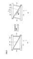
- FIG. 3 is a perspective view showing a drive device in the first embodiment.
- FIG. 3 is a plan view showing the drive device in the first embodiment.
- FIG. 6 is a partially enlarged perspective view of a region surrounded by VII in FIG. 5, and shows a fixing structure of a driving member provided on a base plate. It is a 1st figure which shows the fixing structure of a drive member. It is a 2nd figure which shows the fixation structure of a drive member.
- FIG. 3 is a third view showing a driving member fixing structure.
- FIG. 4 is a fourth view showing a fixing structure of a driving member.
- FIG. 6 is a fifth view showing a fixing structure of a driving member. It is FIG. 6 which shows the fixing structure of a drive member.
- FIG. 7 is a seventh view showing a driving member fixing structure; It is FIG. 8 which shows the fixing structure of a drive member.
- FIG. 10 is a perspective view showing a drive device in a second embodiment.
- FIG. 10 is a plan view showing a drive device in a third embodiment.
- FIG. 10 is a first schematic diagram illustrating a method for positioning a drive device in a third embodiment.
- FIG. 10 is a second schematic diagram illustrating a method for positioning a drive device according to Embodiment 3.
- FIG. 10 is a third schematic diagram illustrating a method for positioning a drive device according to Embodiment 3. It is the 1st schematic diagram explaining rotation control, (A) is a top view and (B) is a side view. It is the 2nd schematic diagram explaining rotation control, (A) is a top view and (B) is a side view. It is FIG. 1 explaining the rotation control in Embodiment 3, (A) is a top view, (B) is a side view. It is FIG. 2 (plan view) explaining rotation control in Embodiment 3.
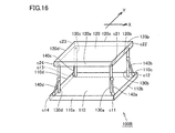
- FIG. 10 is a perspective view showing a drive device in a fourth embodiment.
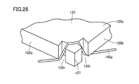
- FIG. 26 is a partially enlarged perspective view of a region surrounded by XXVI in FIG.
- FIG. 10 is a perspective view showing a drive device in a fifth embodiment.
- FIG. 10 is a perspective view showing a drive device in a sixth embodiment.
- FIG. 20 is a perspective view showing a driving device in a seventh embodiment.
- FIG. 20 is a perspective view showing a drive device in an eighth embodiment.
- FIG. 31 is a partially enlarged perspective view of a region surrounded by XXXI in FIG. 30 and shows a structure for fixing a shape memory alloy wire to a support member.
- FIG. 20 is a perspective view showing a drive device in a ninth embodiment.
- FIG. 38 is a perspective view showing a drive device in the tenth embodiment.
- FIG. 38 is a perspective view showing a drive device in the eleventh embodiment.
- FIG. 38 is a first plan view showing an initial position state of a driven plate in the twelfth embodiment.
- FIG. 23 is a second plan view showing an initial position state of a driven plate in the twelfth embodiment.
- FIG. 38 is a perspective view showing a drive device in the thirteenth embodiment.
- FIG. 25 is a perspective view showing a drive device in the fourteenth embodiment.
- FIG. 25 is a perspective view showing a lens unit in the fifteenth embodiment.
- FIG. 28 is a perspective view showing a lens unit in the sixteenth embodiment. It is a functional block diagram explaining camera-shake correction control in a lens unit. It is a flowchart explaining the camera-shake correction control in a lens unit.
- FIG. 23 is a perspective view showing a lens unit in the seventeenth embodiment.
- FIG. 1 is a first schematic diagram illustrating a configuration and a driving principle of a driving apparatus according to an embodiment, where (A) is a diagram illustrating an initial state (before movement), and (B) is a diagram illustrating after movement.
- the driving device 1 includes a base plate (base member) 110 and a driven plate (driven member) 120 that is disposed at a predetermined distance from the base plate 110 and has a flat surface 120p.
- a support member 130 that supports the driven plate 120 is provided between the base plate 110 and the driven plate 120 so that the base plate 110 and the driven plate 120 are coupled and the plane 120p moves in parallel before and after the movement. It has been.
- the base plate 110 may have a flat surface, and the base plate 110 and the driven plate 120 are configured to move in parallel with respect to the flat surface by the support member 130.
- the driving device 1 is provided with a driving member 140 that drives the driven plate 120 so that the plane 120p moves in parallel before and after the movement.
- the driving member 140 is formed between the base plate 110 and the driven plate 120 so as to be inclined from one end side of the driven plate 120 toward the opposite side of the base plate 110 (in a diagonal direction in the side view of FIG. 1). It is built between.
- FIG. 1 shows a case where the driving member 140 is installed between the base plate 110 and the driven plate 120, but the present invention is not limited to this configuration. Other configurations will be described in each embodiment described later.
- the base plate 110 and the driven plate 120 are mainly composed of, for example, a resin molded product.
- the shape of the base plate 110 and the driven plate 120 is, for example, a square shape of about 10 mm ⁇ 10 mm and a thickness of about 0.3 mm to 0.5 mm in plan view. ing. In the drawing, the distance between the upper surface of the base plate 110 and the lower surface of the driven plate 120 is about 7 mm to 8 mm.
- the base plate 110 and the driven plate 120 are held by the support member 130 so as to be parallel to each other. However, if the plane 120p of the driven plate 120 can be translated before and after the movement, the base plate 110 and the driven plate 120 do not need to be arranged in parallel to each other.
- the support member 130 is a suspension wire which is a wire having a wire thickness of about 80 ⁇ m to 100 ⁇ m.
- a linear shape memory alloy wire is used for the driving member 140.
- the shape memory alloy wire for example, a Ni—Ti—Pd shape memory alloy element is used.
- the shape memory alloy wire contracts by heating the shape memory alloy wire by applying a predetermined current to the shape memory alloy wire used for the driving member 140. Moreover, the shape memory alloy wire is restored to the original length by stopping the heating.
- the driven plate 120 is expanded and contracted in the axial direction (linear longitudinal direction) by moving the shape memory alloy wire of the driving member 140 in the drawing. Drive in the direction.
- the support member 130 between the base plate 110 and the driven plate 120 so as to be a parallel link mechanism, the plane 120p is translated before and after the movement.
- the driven plate 120 moves in the X direction with respect to the base plate 110 with the distance between the driven plates 120 being maintained.
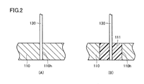
- FIGS. 2A and 2B are schematic views showing a structure of a joint portion of the support member 130 to the base plate 110.
- FIG. 2A is a diagram showing a structure in which the support member 130 is directly joined to the base plate 110
- FIG. It is a figure which shows the structure at the time of providing a low elastic member between 110 and the supporting member 130.
- FIG. 2A is a diagram showing a structure in which the support member 130 is directly joined to the base plate 110
- FIG. It is a figure which shows the structure at the time of providing a low elastic member between 110 and the supporting member 130.
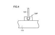
- FIG. 3 is a second schematic diagram illustrating the principle of movement of the driving device, where (A) is a diagram illustrating an initial state (before movement), and (B) is a diagram illustrating after movement.
- FIG. 4 is a schematic diagram illustrating a structure of a joint portion of the support member 130 to the base plate 110, and is a diagram illustrating a structure in which a rotary bearing 130 ⁇ / b> P is provided between the support member 130 and the base plate 110.
- the support member 130 When the support member 130 is rich in elastic deformation, the support member 130 is elastically deformed into a curved shape with reference to FIG. In this case, at the joint portion between the support member 130 and the base plate 110, referring to FIG. 2A, the end portion of the support member 130 may be directly fixed in the fixing hole 110h provided in the base plate 110. it can.
- a low elastic member 111 having lower elasticity than the base plate 110 may be provided between the support member 130 and the base plate 110.
- a rotary bearing 130 ⁇ / b> P may be provided between the support member 130 and the base plate 110 at the joint portion between the support member 130 and the base plate 110.
- FIG. 5 is a perspective view showing drive device 100A in the present embodiment
- FIG. 6 is a plan view showing drive device 100A in the present embodiment. The moving principle described above is applied to the driving device 100A.
- the driving device 100A includes a regular square base plate 110 and a driven plate 120 that is arranged at a predetermined interval with respect to the base plate 110 and has a regular square plane 120p.
- the base plate 110 has a first side 110a, a second side 110b, a third side 110c, and a fourth side 110d. Also, the first corner c11 where the first side 110a and the second side 110b intersect, the second corner c12 where the second side 110b and the third side 110c intersect, and the third side 110c and the fourth side 110d intersect. It has a third corner c13 and a fourth corner c14 where the fourth side 110d and the first side 110a intersect.
- the driven plate 120 has a first side 120a, a second side 120b, a third side 120c, and a fourth side 120d. Also, the first corner c21 where the first side 120a and the second side 120b intersect, the second corner c22 where the second side 120b and the third side 120c intersect, and the third side 120c and the fourth side 120d intersect. It has a third corner c23 and a fourth corner c24 where the fourth side 120d and the first side 120a intersect.
- the direction along the first side 110a and the third side 110c of the base plate 110 is the X direction
- the direction perpendicular to the X direction along the second side 110b and the fourth side 110d of the base plate 110 is the Y direction.
- a first support member 130a and a first drive member 140a are provided between the vicinity of the first corner c11 of the base plate 110 and the vicinity of the first corner c21 of the driven plate 120. Between the vicinity of the second corner c12 of the base plate 110 and the vicinity of the second corner c22 of the driven plate 120, a second support member 130b and a second driving member 140b are provided.
- a third support member 130c and a third drive member 140c are provided between the vicinity of the third corner c13 of the base plate 110 and the vicinity of the third corner c23 of the driven plate 120. Between the vicinity of the fourth corner c14 of the base plate 110 and the vicinity of the fourth corner c24 of the driven plate 120, a fourth support member 130d and a fourth driving member 140d are provided.
- the first driving member 140a, the second driving member 140b, the third driving member 140c, and the fourth driving member 140d have a center (center of gravity).
- the first drive member 140a and the third drive member 140c are arranged at a point-symmetrical position
- the second drive member 140b and the fourth drive member 140d are arranged at a point-symmetrical position. Yes.
- first drive member 140a and the second drive member 140b are arranged in a line-symmetrical position with respect to the X axis passing through the center position P, and the third drive member 140c and the fourth drive member 140d are line-connected. It is arranged at a symmetrical position.
- the driving device 100A having the above-described configuration, for example, when a predetermined current is simultaneously supplied to the first driving member 140a and the second driving member 140b, the first driving member 140a and the second driving member 140b contract, The third drive member 140c and the fourth drive member 140d are stretched. As a result, the plane 120p of the driven plate 120 translates in the X direction.
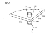
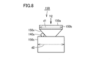
- FIG. 7 is a partially enlarged perspective view of a region surrounded by VII in FIG. 5 and shows a fixing structure of each driving member provided on the base plate, and FIGS. 8 to 15 show a fixing structure of the driving member. It is FIG. 1 to FIG.
- the fixing structure of the driving member provided in the vicinity of the first corner c11 of the base plate 110 is described, but also in the second corner c12, the third corner c13, and the fourth corner c14. It is the same. Further, although the structure for fixing each driving member to the base plate 110 has been described, the structure for fixing each driving member to the driven plate 120 is the same.
- a rod-shaped fixing member 150 is provided in the vicinity of the first corner c ⁇ b> 11 of the base plate 110 so as to penetrate the front and back of the base plate 110.
- One end of the first driving member 140a is connected to the fixing member 150 on the surface side of the base plate 110.
- a lead wire 160 connected to a control device provided outside is connected to the fixing member 150 on the back surface side of the base plate 110.
- the fixing member 150 has a V-shaped groove 150v formed around the side surface, and the first driving member 140a is sandwiched in the groove 150v.
- the end portion 150b that is the caulking portion of the fixing member 150 is deformed, and the first driving member 140a is crimped (fixed).
- the diameter d1 of the end 150b is made smaller than the diameter d2 of the non-deformed portion 150c.
- the non-deforming portion 150c is pressed to press-fit.
- the diameter d1 of the end portion 150b is made smaller than the diameter d2 of the non-deformed portion 150c so that the end portion 150b is not caught in the press-fitting hole of the base plate 110.
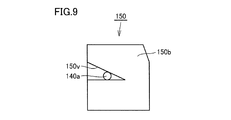
- Fig. 9 shows another shape of the caulking portion.
- the groove 150v may be formed in a V shape in a part of the side surface of the end 150b of the fixing member 150.
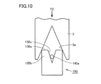
- FIG. 10 shows still another shape of the caulking portion.
- the groove 150v may be formed in the end surface 150a of the fixing member 150.
- the fixing member 150 is caulked by applying the caulking jig 5 having the taper 5a formed on the inner surface thereof to the end portion 150b of the fixing member 150 and pressing in the Y2 direction.
- FIG. 11 shows still another shape of the caulking portion.
- a taper 150 t may be formed at the end 150 b of the fixing member 150.
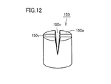
- FIG. 12 shows still another shape of the caulking portion.
- Two grooves 150v may be formed on the end surface 150a of the fixing member 150 in a cross shape. This increases the degree of freedom in the rotational direction when the fixing member 150 is press-fitted into the base plate 110.
- FIG. 13 shows still another shape of the caulking portion.
- a taper 150 t may be formed at the end 150 b of the fixing member 150. As a result, it is possible to prevent catching when the fixing member 150 is fixed to the base plate 110 by press fitting.
- FIGS. 8 to 13 can be easily processed by known machining.
- the shape of the fixing member 150 is formed in a cylindrical shape or a polygonal column shape. As shown in FIG. 8, when the groove 150v is formed around the side surface of the fixing member 150, the fixing member 150 is not required to be fixed to the base plate 110. As shown in FIG. 14, the shape is preferably cylindrical.
- the shape of the fixing member 150 is preferably a polygonal column shape having directionality as shown in FIG.
- the fixing member 150 shown in FIG. 15 is formed in the shape of an octagonal column as an example, it is not limited to this.
- the shape may be an N prism (N is a positive integer) or a D cut shape.
- the material of the fixing member 150 since the first driving member 140a is held by the elastic force of the caulking fixing member 150, SUS steel or copper having a Young's modulus of about 50 GPa to 250 GPa in view of the holding force and the caulking pressure. It is preferable to use a metallic material.
- the metal material can be prepared so that a desired Young's modulus can be obtained by alloy ratio, additive content or heat treatment.
- a desired Young's modulus can be obtained by alloy ratio, additive content or heat treatment.
- SUS steel it is adjusted so as to be in an optimum state for caulking by its alloy composition or heat treatment.
- the copper-based metal refers to an alloy mainly composed of copper including pure copper, and is adjusted so as to be in an optimum state for caulking by the alloy composition or heat treatment as in the case of SUS steel.
- a copper-based metal since it is easy to cut and can be directly soldered to the material, the manufacturing cost can be suppressed without requiring a plating process described later.
- Nickel plating treatment is preferably performed.
- the fixing of the first driving member 140a and the connection of the energizing member for supplying current to the first driving member 140a are performed using one rod-like member, that is, the fixing member 150, and this fixing member 150 is connected to the base plate. It was made to fix in the aspect penetrated to 110. As a result, the fixing member 150 can be disposed in a small space corresponding to the cross-sectional area in the radial direction, and the apparatus can be downsized.
- FIG. 16 is a perspective view showing drive device 100B in the present embodiment. Note that the same or corresponding portions as those of drive device 100A in the first embodiment are given the same reference numerals, and redundant description will not be repeated.
- the driving device 100A a configuration in which the first driving member 140a to the fourth driving member 140d are installed between the base plate 110 and the driven plate 120 is employed.
- the driving device 100B in the present embodiment a configuration in which the first driving member 140a to the fourth driving member 140d are respectively installed between the driven plate 120 and the first support member 130a to the fourth support member 130b is employed. is doing.
- FIG. 17 is a plan view showing drive device 100C in the present embodiment. Note that the same or corresponding portions as those of drive device 100A in the first embodiment are given the same reference numerals, and redundant description will not be repeated.
- the driving device 100C a configuration is adopted in which eight driving members from the first driving member 140a1 to the eighth driving member 140d2 are installed between the base plate 110 and the driven plate 120.
- First driving member 140a1 Specifically, on the first side 120a side of the driven plate 120, one end of the first driving member 140a1 is fixed in the vicinity of the first corner c21 (first location) of the driven plate 120, so that the first driving The other end of the member 140a1 is fixed in the vicinity of the fourth corner c14 (eighth place) of the base plate 110. Therefore, the first driving member 140a1 is installed between the base plate 110 and the driven plate 120 so as to be inclined from one end side of the driven plate 120 toward the opposite side of the base plate 110.
- hird driving member 140b1 Similarly, on the second side 120b side of the driven plate 120, one end of the third driving member 140b1 is fixed in the vicinity of the second corner c22 (second location) of the driven plate 120, and the third driving member 140b1. The other end of the base plate 110 is fixed in the vicinity of the first corner c11 (fifth location) of the base plate 110. Accordingly, the third driving member 140b1 is installed between the base plate 110 and the driven plate 120 so as to be inclined from one end side of the driven plate 120 toward the opposite side of the base plate 110.
- the fourth driving member 140b2 is formed between the base plate 110 and the driven plate 120 so as to be inclined from one end side of the driven plate 120 toward the opposite side of the base plate 110 (intersects with the third driving member 140b1). It is built between.
- the eighth driving member 140d2 is inclined between the base plate 110 and the driven plate 120 so as to be inclined from one end side of the driven plate 120 toward the opposite side of the base plate 110 (intersects with the seventh driving member 140d1). It is built between.
- the driven plate 120 includes a first corner c21 (first location), a second corner c22 (second location), and a third corner c23 (third location). Portion) and a fourth corner portion c24 (fourth portion), and a third corner portion at a position facing the first corner portion c21 (first portion) across the center of the driven plate 120. c23 (third location) is located, and the fourth corner c24 (fourth location) is located at a position facing the second corner c22 (second location) across the center of the driven plate 120. is doing.
- the base plate 110 includes a first corner c11 (fifth location), a second corner c12 (sixth location), and a third corner c13 (seventh location).
- the fourth corner c14 (eighth location), the first corner c11 (fifth location) is located opposite to the first corner c21 (first location), The second corner c12 (sixth location) is positioned to face the second corner c22 (second location), and the third corner c13 (seventh location) is the third corner.
- the fourth corner c14 (eighth location) is located opposite to the c23 (third location), and the fourth corner c24 (fourth location) is located opposite to the fourth corner c24 (fourth location).
- FIGS. 18 to 20 are first to third schematic diagrams showing a positioning method of the driving device 100C.
- first driving member 140 a 1 and fourth driving member 140 b 2 contract and driven plate 120 is driven.
- a predetermined current is simultaneously applied to first drive member 140a1, fourth drive member 140b2, seventh drive member 140d1, and second drive member 140a2.
- the first driving member 140a1, the fourth driving member 140b2, the seventh driving member 140d1, and the second driving member 140a2 are contracted, and the driven plate 120 is moved in the arrow Y direction as shown in FIG.
- the heading force acts.
- a predetermined current may be simultaneously supplied to the fourth driving member 140b2 and the seventh driving member 140d1.
- the driven plate 120 can be translated in an arbitrary movement direction.
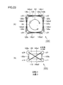
- FIGS. 21 and 22 are first and second schematic diagrams for explaining the rotation control, in which (A) is a plan view and (B) is a side view, respectively.
- FIG. 23 is a first diagram illustrating rotation control in the third embodiment, where (A) is a plan view and (B) is a side view.
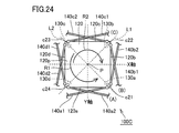
- FIG. 24 is a second diagram (plan view) for explaining the rotation control in the third embodiment.
- a drive member is provided between the vicinity of the side surface of the base plate 110 and the vicinity of the side surface of the driven plate 120, and the driven plate 120 is moved in the X direction. Generates a force (rotational force) for rotating the driven plate 120 in the R1 direction or the R2 direction.
- the rotation of the driven plate 120 can be suppressed by increasing the rigidity of the first support member 130a to the fourth support member 130d (increasing the diameter). it can. However, since the rigidity of the first support member 130a to the fourth support member 130d is high, the force required to bend the first support member 130a to the fourth support member 130d increases.
- the fourth drive member 140b2, the second drive member 140a2 and the third drive member 140b1, the fifth drive member 140c1 and the eighth drive member 140d2, and the sixth drive member 140c2 and the seventh drive member 140d1 are line symmetric. It is arranged to be.
- the X and Y axes passing through the center P are symmetrical with respect to the diagonal line L1 of the driven plate 120 passing through the center P.
- each drive member can control the movement of driven plate 120 and also can suppress the rotational force generated on driven plate 120. It is possible to use the first support member 130a to the fourth support member 130d that can reduce the force required to move 120 and are easily bent. As a result, it is possible to reduce the size (thinner thickness and height) of the driving device.
- one end of the two first drive members 140a1 and the fourth drive member 140b2 is different from the fourth corner c14 and the second corner of the base plate 110.
- the other end of the two first drive members 140a1 and the fourth drive member 140b2 is fixed to the corner c12, and is fixed to the first corner c21 that is the same location of the driven plate 120. .
- one end of the two second driving members 140a2 and the third driving member 140b1 is fixed to a fourth corner c24 and a second corner c22 which are different positions of the driven plate 120, and 2
- the other ends of the second driving member 140 a 2 and the third driving member 140 b 1 are fixed to a first corner c 11 that is the same location of the base plate 110. The same applies to the fixing of one end and the other end of the other driving members.
- FIG. 25 is a perspective view showing drive device 100D in the present embodiment
- FIG. 26 is a partially enlarged perspective view of a region surrounded by XXVI in FIG. 25, where a shape memory alloy wire that is a drive member is driven. It is a figure which shows the fixation structure to a plate. Note that the same or corresponding portions as those of drive device 100C in the third embodiment are given the same reference numerals, and redundant description will not be repeated.
- the first driving member 140a1 and the fourth driving member 140b2 according to the third embodiment are used.
- a single shape memory alloy wire is used as the first drive member 140a
- a single shape memory alloy wire is used as the second drive member 140b using the third drive member 140b1 and the sixth drive member 140c2.
- the shape memory alloy wire integrated into the fifth drive member 140c1 and the eighth drive member 140d2 is used as the third drive member 140c, and is integrated into the second drive member 140a2 and the seventh drive member 140d1.
- a configuration is adopted in which the fourth drive member 140d is formed using a shape memory alloy wire.
- both end portions of each drive member are fixed to the base plate 110, and an intermediate region of each drive member 140 is , Fixed to the driven plate 120.
- the first drive member 140a is fixed to the driven plate 120 in the intermediate region of the first drive member 140a in the notch region 120r provided in the vicinity of the first corner portion c21 of the driven plate 120. Engage.
- the fixing of the intermediate region of the other driving member to the driven plate 120 is the same.
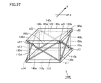
- FIG. 27 is a perspective view showing drive device 100E in the present embodiment. Note that the same or corresponding portions as those of drive device 100C in the third embodiment are given the same reference numerals, and redundant description will not be repeated.
- the first driving member 140a1 and the eighth driving member 140d2 according to the third embodiment are used.
- a single shape memory alloy wire is used as the first drive member 140a
- a single shape memory alloy wire is used as the second drive member 140b using the second drive member 140a2 and the third drive member 140b1.
- the fourth drive member 140b2 and the fifth drive member 140c1 are unified into the sixth drive member 140c2 and the seventh drive member 140d1 as the third drive member 140c using the shape memory alloy wire unified into the fourth drive member 140b2 and the fifth drive member 140c1.
- a configuration is adopted in which the fourth drive member 140d is formed using a shape memory alloy wire.
- both end portions of each driving member are fixed to the driven plate 120, and intermediate between the driving members 140.
- the region is fixed to the base plate 110.
- the structure shown in FIG. 26 can be applied to fixing the intermediate region of the first drive member 140a1 to the base plate 110.
- FIG. 28 is a perspective view showing drive device 100F in the present embodiment. Note that the same or corresponding portions as those of drive device 100C in the third embodiment are given the same reference numerals, and redundant description will not be repeated.
- FIG. 28 shows a case where the driving member 140 is formed by using the shape memory alloy wire integrated into the first driving member 140a1 and the sixth driving member 140c2 shown in the third embodiment (see FIG. 17). Show. An intermediate region of the driving member 140 is fixed along the second side 120 b of the driven plate 120.
- the shape memory alloy wires unified into the third driving member 140b1 and the eighth driving member 140d2 shown in the third embodiment are used, and the intermediate region is defined as the first plate of the driven plate 120.
- the configuration fixed along the three sides 120c, the shape memory alloy wire unified into the second driving member 140a2 and the fifth driving member 140c1 shown in the third embodiment, and the intermediate region in the driven plate 120 The configuration fixed along the fourth side 120d and the shape memory alloy wire integrated into the fourth drive member 140b2 and the seventh drive member 140d1 shown in the third embodiment, and the intermediate region, By adopting the configuration of fixing along the first side 120a of the driven plate 120, the same configuration as the driving device 100C of the third embodiment can be realized.
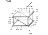
- FIG. 29 is a perspective view showing drive device 100G in the present embodiment. Note that the same or corresponding portions as those of drive device 100C in the third embodiment are given the same reference numerals, and redundant description will not be repeated.
- FIG. 29 shows a case where the driving member 140 is formed using the shape memory alloy wire integrated into the second driving member 140a2 and the fifth driving member 140c1 shown in the third embodiment.
- An intermediate region of the driving member 140 is fixed along the second side 110 b of the base plate 110.
- the shape memory alloy wire integrated into the fourth driving member 140b2 and the seventh driving member 140d1 shown in the third embodiment is used, and the intermediate region is defined as the third side of the base plate 110.
- 110c a shape memory alloy wire integrated into the first driving member 140a1 and the sixth driving member 140c2 shown in the third embodiment, and the intermediate region is the fourth side of the base plate 110.
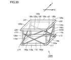
- FIG. 30 is a perspective view showing drive device 100H in the present embodiment
- FIG. 31 is a partially enlarged perspective view of a region surrounded by XXXI in FIG. 30, and a structure for fixing a shape memory alloy wire to a support member FIG. Note that the same or corresponding portions as those of drive device 100D in the fourth embodiment are given the same reference numerals, and redundant description will not be repeated.
- the driving device 100H in the present embodiment is a modification of the driving device 100D in the fourth embodiment.
- the intermediate region of each driving member 140 is fixed to the driven plate 120.
- the driving device 100H in the present embodiment has the driving members 140a to 140d.
- the intermediate region is fixed to each of the support members 130a to 130d.
- each of the support members 130a to 130d is provided with a hook-shaped engaging portion 130e that protrudes outward, and the engaging portion 130e has, for example, an intermediate region of the first drive member 140a. Can be engaged. The same applies to other driving members.
- FIG. 32 is a perspective view showing drive device 100I in the present embodiment. Note that the same or corresponding portions as those of drive device 100E in the fifth embodiment are denoted by the same reference numerals, and redundant description will not be repeated.
- the driving device 100I in the present embodiment is a modification of the driving device 100E in the fifth embodiment.
- the driving device 100E in the fifth embodiment the case where the driving members 140a to 140d are fixed to the driven plate 120 is shown, but the driving device 100I in the present embodiment is the end of each driving member 140a to 140d.
- the partial area is fixed to each of the support members 130a to 130d.
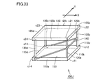
- FIG. 33 is a perspective view showing drive device 100J in the present embodiment. Note that the same or corresponding portions as those of drive device 100F in the sixth embodiment are denoted by the same reference numerals, and redundant description will not be repeated.
- the driving device 100J in the present embodiment is a modification of the driving device 100F in the sixth embodiment.
- the intermediate region of each driving member 140 is fixed to the driven plate 120, but the driving device 100J according to the present embodiment is an intermediate region of each driving member 140. Is fixed to the first support member 130a and the second support member 130b.
- the structure shown in FIG. 31 can be applied to the structure for fixing the intermediate region of the drive member 140 to the first support member 130a and the second support member 130b.
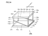
- FIG. 34 is a perspective view showing drive device 100K in the present embodiment. Note that the same or corresponding portions as those of drive device 100G in the seventh embodiment are denoted by the same reference numerals, and redundant description will not be repeated.
- the driving device 100K in the present embodiment is a modification of the driving device 100G in the seventh embodiment.
- the driving device 100G in the seventh embodiment the case where the end region of each driving member 140 is fixed to the driven plate 120 is shown.
- the driving device 100K in the present embodiment has an end of each driving member 140.
- the partial region is fixed to the third support member 130c and the fourth support member 130d.
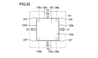
- FIGS. 35 and 36 are first and second plan views showing an initial position state of the driven plate.
- driven plate 120 is positioned at the center position of movement range A1 of driven plate 120 surrounded by the dotted line in FIG. 35 as the initial position. ing.
- being located at the center means a state in which the center of the driven plate 120 and the center position of the movement range A1 overlap, and the movable amount in the X1, X2, Y1, and Y2 directions is the same.
- the expansion / contraction amount of each driving device is set so as to be the same.
- the driven plate 120 may be located at a position shifted from the center of the movement range A1 of the driven plate 120 as the initial position. As a result, it is possible to define the movement range of the driven plate 120 corresponding to the configuration of various units on which the present driving device is mounted.
- FIG. 37 is a perspective view showing drive device 100L in the present embodiment. Note that FIG. 37 illustrates the case where the base plate structure of the present embodiment is adopted for the driving device 100D of the fourth embodiment shown in FIG. 25, but the driving device of the other embodiments is described. However, it is possible to apply the base plate structure of the present embodiment.
- the base plate 110 in each of the above embodiments is composed of a single plate member
- the base plate 110A in this embodiment is provided individually for each of the support members 130a to 130d. Even with this configuration, it is possible to obtain the same effects as those of the driving device 100D of the fourth embodiment.
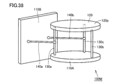
- FIG. 38 is a perspective view showing drive device 100M in the present embodiment.
- Each drive device in each of the above embodiments uses four support members 130a to 130d, and when each drive member 140 is fixed to the base plate 110, each drive member 140, support member 130, and The structure which was fixed was adopted. However, it is not limited to this structure.
- the three support members 130a to 130c can be arranged so as to be at the apex position of the triangle. It is also possible to prepare a base plate 110B different from the base plate 110A to which the three support members 130a to 130c are fixed, and to adopt a structure in which the driving member 140 is fixed to the base plate 110B.
- the shape of the base plate 110A and the driven plate 120 is not limited to a quadrangle, and may be a circular shape.
- FIG. 39 is a perspective view showing a lens unit 200A in the present embodiment.
- the lens unit 200A in the present embodiment uses the driving device 100D in the fourth embodiment. Therefore, the same portions as those of drive device 100D are denoted by the same reference numerals, and redundant description will not be repeated.
- the lens unit 200A includes a lens 210 provided on the driven plate 120, and an image sensor 220 disposed on the base plate 110 at an imaging position of light that has passed through the lens 210.
- the lens unit 200A can change the imaging position of the lens 210 with respect to the image sensor 220 by moving the lens 210 in parallel by appropriately extending and contracting the driving members 140a to 140d made of shape memory alloy wires in the axial direction. To do. A detailed driving method will be described later.
- FIG. 40 is a perspective view showing a lens unit 200B in the present embodiment.
- the lens unit 200B in the present embodiment uses the drive device 100E in the fifth embodiment. Therefore, the same portions as those of drive device 100E are denoted by the same reference numerals, and redundant description will not be repeated.
- the lens unit 200B includes a lens 210 provided on the driven plate 120, and an imaging element 220 disposed on the base plate 110 at an imaging position of light passing through the lens 210. ing.
- the lens unit 200B can change the imaging position of the lens 210 with respect to the image sensor 220 by moving the lens 210 in parallel by appropriately expanding and contracting the driving members 140a to 140d made of shape memory alloy wires. To do. A detailed driving method will be described later.
- FIG. 41 is a functional block diagram for explaining camera shake correction control in the lens unit
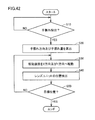
- FIG. 42 is a flowchart for explaining camera shake correction control in the lens unit
- 43 to 45 are first to third perspective views for explaining camera shake correction in the lens unit, and a case where the lens unit 200A in Embodiment 15 shown in FIG. 39 is used as the lens unit will be described. The same applies to the case where the lens unit 200B according to the sixteenth embodiment shown in FIG. 40 is used.
- the device 1000 includes an angular velocity sensor 300 that detects a shake in the X direction and an angular velocity sensor 400 that detects a shake in the Y direction. Signals from the angular velocity sensors 300 and 400 are input to the analog signal processing circuit 500. A predetermined signal is exchanged between the analog signal processing circuit 500 and the camera shake correction microcomputer 600. The control signal output from the camera shake correction microcomputer 600 is transmitted to the lens unit 200A via the actuator driver 700.
- the camera shake correction control in the camera shake correction microcomputer 600 first detects camera shake based on signals from the angular velocity sensors 300 and 400 (step 10, hereinafter referred to as S10). Next, when a camera shake is detected, a camera shake direction and a camera shake amount are calculated (S20). Next, the driven plate 120 of the lens unit 200A is moved in the X direction and the Y direction (S40).
- the lens unit position is detected based on the length of each driving member 140.
- each driving member 140 For example, by energizing each driving member 140 so as to have a resistance value corresponding to the target moving position for positioning the lens unit at the target position, and deforming the shape of each driving member 140, the lens unit is moved to the target moving position. Move to.
- the initial start resistance value determined in advance as the resistance value of each drive member 140 when the lens unit starts moving in the initial stage, and each drive when the lens unit is located at a predetermined movement position The position of the lens unit can be detected by storing in advance a difference value from the post-movement resistance value that is the resistance value of the member 140 and detecting the resistance value of each driving member 140.
- FIGS. FIG. 43 shows a case where there is no camera shake in the lens unit 200A, and an image is formed at a predetermined position P1 of the image sensor 220 by the light r1 that has passed through the lens 210.
- the light r1 that has passed through the lens 210 does not form an image at a predetermined position P1 of the image sensor 220, but forms an image at a shifted position P2.
- driven plate 120 is moved in the X direction and the Y direction so that an image is formed at a predetermined position P1 of image sensor 220. .
- camera shake correction can be performed in a device (for example, a digital camera) 1000 in which the lens unit 200A is mounted.
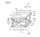
- FIG. 46 is a perspective view showing a lens unit 200C in the present embodiment.
- the lens unit 200A of the fifteenth embodiment shown in FIG. 39 includes the lens 210 on the driven plate 120 and the image sensor 220 on the base plate 110
- the lens unit 200C in the present embodiment includes The base plate 110 includes a lens 210 and the driven plate 120 includes an image sensor 220.
- the same effect as the lens unit 200A in the fifteenth embodiment can be obtained by controlling the position of the image sensor.
- the configuration of the present embodiment can be adopted for the lens unit 200C in the sixteenth embodiment.
Abstract
Description
他の形態において、2本の上記形状記憶合金線は、設定された軸に対して、線対称となる位置に配置されている。 In another form, the drive member includes two shape memory alloy wires.
In another embodiment, the two shape memory alloy wires are arranged at positions that are line-symmetric with respect to a set axis.
形状記憶合金線として、上記第1の箇所と上記第8の箇所との間に架設された第1の形状記憶合金線と、上記第4の箇所と上記第5の箇所との間に架設された第2の形状記憶合金線と、上記第2の箇所と上記第5の箇所との間に架設された第3の形状記憶合金線と、上記第1の箇所と上記第6の箇所との間に架設された第4の形状記憶合金線と、上記第3の箇所と上記第6の箇所との間に架設された第5の形状記憶合金線と、上記第2の箇所と上記第7の箇所との間に架設された第6の形状記憶合金線と、上記第4の箇所と上記第7の箇所との間に架設された第7の形状記憶合金線と、上記第3の箇所と上記第8の箇所との間に架設された第8の形状記憶合金線と、を有する。
As a shape memory alloy wire, it is installed between the first shape memory alloy wire laid between the first location and the eighth location, and the fourth location and the fifth location. The second shape memory alloy wire, the third shape memory alloy wire constructed between the second location and the fifth location, the first location and the sixth location. A fourth shape memory alloy wire laid between, a fifth shape memory alloy wire laid between the third location and the sixth location, the second location and the seventh location. A sixth shape memory alloy wire erected between the second location, a seventh shape memory alloy wire erected between the fourth location and the seventh location, and the third location. And an eighth shape memory alloy wire laid between the eighth portion and the eighth portion.
他の形態において、上記支持部材と上記ベース部材との接合部において、上記支持部材と上記ベース部材との間には、上記ベース部材よりも弾性が小さい低弾性部材が設けられている。 In another embodiment, the support member is a wire.
In another embodiment, a low elastic member having elasticity smaller than that of the base member is provided between the support member and the base member at a joint portion between the support member and the base member.
図1を参照して、本発明に基づいた駆動装置の構成および移動原理について説明する。図1は、実施の形態における駆動装置の構成および駆動原理を示す第1模式図であり、(A)は初期状態(移動前)を示す図、(B)は移動後を示す図である。 (Configuration of drive unit and principle of movement)
With reference to FIG. 1, the configuration and principle of movement of a drive device according to the present invention will be described. FIG. 1 is a first schematic diagram illustrating a configuration and a driving principle of a driving apparatus according to an embodiment, where (A) is a diagram illustrating an initial state (before movement), and (B) is a diagram illustrating after movement.
支持部材130とベースプレート110との接合について、図2から図4を参照して説明する。図2は、支持部材130のベースプレート110への接合部の構造を示す模式図であり、(A)は、ベースプレート110に支持部材130を直接接合させた構造を示す図、(B)は、ベースプレート110と支持部材130との間に低弾性部材を設けた場合の構造を示す図である。 (Join of
The joining of the
図5および図6を参照して、実施の形態1における駆動装置100Aについて説明する。図5は、本実施の形態における駆動装置100Aを示す斜視図、図6は、本実施の形態における駆動装置100Aを示す平面図である。この駆動装置100Aには、上記で説明した移動原理が適用される。 (Embodiment 1)
With reference to FIGS. 5 and 6, drive device 100 </ b> A in the first embodiment will be described. FIG. 5 is a perspective view showing
次に、第1駆動部材140aから第4駆動部材140dの固定構造について、図7から図15を参照して説明する。図7は、図5中のVIIで囲まれた領域の部分拡大斜視図であり、ベースプレートに設けられる各駆動部材の固定構造を示す図、図8から図15は、駆動部材の固定構造を示す第1から第8図である。 (Drive member fixing structure)
Next, a fixing structure of the
次に、図16を参照して、実施の形態2における駆動装置100Bについて説明する。図16は、本実施の形態における駆動装置100Bを示す斜視図である。なお、上記実施の形態1における駆動装置100Aと同一または相当箇所については、同一の参照番号を付し、重複する説明は繰り返さない。 (Embodiment 2)
Next, with reference to FIG. 16, the driving
次に、図17を参照して、実施の形態3における駆動装置100Cについて説明する。図17は、本実施の形態における駆動装置100Cを示す平面図である。なお、上記実施の形態1における駆動装置100Aと同一または相当箇所については、同一の参照番号を付し、重複する説明は繰り返さない。 (Embodiment 3)
Next, with reference to FIG. 17, a driving
具体的には、被駆動プレート120の第1辺120a側において、第1駆動部材140a1の一端が被駆動プレート120の第1角部c21(第1の箇所)の近傍に固定され、第1駆動部材140a1の他端がベースプレート110の第4角部c14(第8の箇所)の近傍に固定されている。したがって、第1駆動部材140a1は、被駆動プレート120の一端側からベースプレート110の反対側に向けて傾斜するように、ベースプレート110と被駆動プレート120との間に架設されている。 (First driving member 140a1)
Specifically, on the
また、被駆動プレート120の第1辺120a側において、第2駆動部材140a2の一端が被駆動プレート120の第4角部c24(第4の箇所)の近傍に固定され、第2駆動部材140a2の他端がベースプレート110の第1角部c11(第5の箇所)の近傍に固定されている。したがって、第2駆動部材140a2は、被駆動プレート120の一端側からベースプレート110の反対側に向けて傾斜する(第1駆動部材140a1とは交差する)ように、ベースプレート110と被駆動プレート120との間に架設されている。 (Second drive member 140a2)
Further, on the
同様に、被駆動プレート120の第2辺120b側において、第3駆動部材140b1の一端が被駆動プレート120の第2角部c22(第2の箇所)の近傍に固定され、第3駆動部材140b1の他端がベースプレート110の第1角部c11(第5の箇所)の近傍に固定されている。したがって、第3駆動部材140b1は、被駆動プレート120の一端側からベースプレート110の反対側に向けて傾斜するように、ベースプレート110と被駆動プレート120との間に架設されている。 (Third driving member 140b1)
Similarly, on the
また、被駆動プレート120の第2辺120b側において、第4駆動部材140b2の一端が被駆動プレート120の第1角部c21(第1の箇所)の近傍に固定され、第4駆動部材140b2の他端がベースプレート110の第2角部c12(第6の箇所)の近傍に固定されている。したがって、第4駆動部材140b2は、被駆動プレート120の一端側からベースプレート110の反対側に向けて傾斜する(第3駆動部材140b1とは交差する)ように、ベースプレート110と被駆動プレート120との間に架設されている。 (Fourth drive member 140b2)
Further, on the
同様に、被駆動プレート120の第3辺120c側において、第5駆動部材140c1の一端が被駆動プレート120の第3角部c23(第3の箇所)の近傍に固定され、第5駆動部材140c1の他端がベースプレート110の第2角部c12(第6の箇所)の近傍に固定されている。したがって、第5駆動部材140c1は、被駆動プレート120の一端側からベースプレート110の反対側に向けて傾斜するように、ベースプレート110と被駆動プレート120との間に架設されている。 (Fifth drive member 140c1)
Similarly, on the
また、被駆動プレート120の第3辺120c側において、第6駆動部材140c2の一端が被駆動プレート120の第2角部c22(第2の箇所)の近傍に固定され、第6駆動部材140c2の他端がベースプレート110の第3角部c13(第7の箇所)の近傍に固定されている。したがって、第6駆動部材140c2は、被駆動プレート120の一端側からベースプレート110の反対側に向けて傾斜する(第5駆動部材140c1とは交差する)ように、ベースプレート110と被駆動プレート120との間に架設されている。 (Sixth drive member 140c2)
Further, on the
同様に、被駆動プレート120の第4辺120d側において、第7駆動部材140d1の一端が被駆動プレート120の第4角部c24(第4の箇所)の近傍に固定され、第7駆動部材140d1の他端がベースプレート110の第3角部c13(第7の箇所)の近傍に固定されている。したがって、第7駆動部材140d1は、被駆動プレート120の一端側からベースプレート110の反対側に向けて傾斜するように、ベースプレート110と被駆動プレート120との間に架設されている。 (Seventh drive member 140d1)
Similarly, on the
また、被駆動プレート120の第4辺120d側において、第8駆動部材140d2の一端が被駆動プレート120の第3角部c23(第3の箇所)の近傍に固定され、第8駆動部材140d2の他端がベースプレート110の第4角部c14(第8の箇所)の近傍に固定されている。したがって、第8駆動部材140d2は、被駆動プレート120の一端側からベースプレート110の反対側に向けて傾斜する(第7駆動部材140d1とは交差する)ように、ベースプレート110と被駆動プレート120との間に架設されている。 (Eighth drive member 140d2)
In addition, on the
上記構成からなる駆動装置100Cを用いた場合の駆動装置の位置決め方法について、図18から図20を参照して説明する。図18から図20は、駆動装置100Cの位置決め方法を示す第1から第3模式図である。 (Driver positioning method)
A positioning method of the driving device when the
ここで、図21から図24を参照して、被駆動プレート120の回転規制について説明する。図21および図22は、回転制御を説明する第1および第2模式図であり、それぞれ(A)は平面図、(B)は側面図である。図23は、実施の形態3における回転制御を説明する第1図であり、(A)は平面図、(B)は側面図である。図24は、実施の形態3における回転制御を説明する第2図(平面図)である。 (Rotation regulation)
Here, with reference to FIGS. 21 to 24, the rotation restriction of the driven
次に、図25および図26を参照して、実施の形態4における駆動装置100Dについて説明する。図25は、本実施の形態における駆動装置100Dを示す斜視図、図26は、図25中のXXVIで囲まれた領域の部分拡大斜視図であり、駆動部材である形状記憶合金線の被駆動プレートへの固定構造を示す図である。なお、上記実施の形態3における駆動装置100Cと同一または相当箇所については、同一の参照番号を付し、重複する説明は繰り返さない。 (Embodiment 4)
Next, with reference to FIGS. 25 and 26,
次に、図27を参照して、実施の形態5における駆動装置100Eについて説明する。図27は、本実施の形態における駆動装置100Eを示す斜視図である。なお、上記実施の形態3における駆動装置100Cと同一または相当箇所については、同一の参照番号を付し、重複する説明は繰り返さない。 (Embodiment 5)
Next, with reference to FIG. 27, a
次に、図28を参照して、実施の形態6における駆動装置100Fについて説明する。図28は、本実施の形態における駆動装置100Fを示す斜視図である。なお、上記実施の形態3における駆動装置100Cと同一または相当箇所については、同一の参照番号を付し、重複する説明は繰り返さない。 (Embodiment 6)
Next, with reference to FIG. 28, a driving
次に、図29を参照して、実施の形態7における駆動装置100Gについて説明する。図29は、本実施の形態における駆動装置100Gを示す斜視図である。なお、上記実施の形態3における駆動装置100Cと同一または相当箇所については、同一の参照番号を付し、重複する説明は繰り返さない。 (Embodiment 7)
Next, with reference to FIG. 29, the
次に、図30および図31を参照して、実施の形態8における駆動装置100Hについて説明する。図30は、本実施の形態における駆動装置100Hを示す斜視図、図31は、図30中のXXXIで囲まれた領域の部分拡大斜視図であり、形状記憶合金線の支持部材への固定構造を示す図である。なお、上記実施の形態4における駆動装置100Dと同一または相当箇所については、同一の参照番号を付し、重複する説明は繰り返さない。 (Embodiment 8)
Next, with reference to FIGS. 30 and 31, drive device 100 </ b> H in the eighth embodiment will be described. 30 is a perspective view showing
次に、図32を参照して、実施の形態9における駆動装置100Iについて説明する。図32は、本実施の形態における駆動装置100Iを示す斜視図である。なお、上記実施の形態5における駆動装置100Eと同一または相当箇所については、同一の参照番号を付し、重複する説明は繰り返さない。 (Embodiment 9)
Next, with reference to FIG. 32, a driving apparatus 100I according to the ninth embodiment will be described. FIG. 32 is a perspective view showing drive device 100I in the present embodiment. Note that the same or corresponding portions as those of
次に、図33を参照して、実施の形態10における駆動装置100Jについて説明する。図33は、本実施の形態における駆動装置100Jを示す斜視図である。なお、上記実施の形態6における駆動装置100Fと同一または相当箇所については、同一の参照番号を付し、重複する説明は繰り返さない。 (Embodiment 10)
Next, with reference to FIG. 33,
次に、図34を参照して、実施の形態11における駆動装置100Kについて説明する。図34は、本実施の形態における駆動装置100Kを示す斜視図である。なお、上記実施の形態7における駆動装置100Gと同一または相当箇所については、同一の参照番号を付し、重複する説明は繰り返さない。 (Embodiment 11)
Next, with reference to FIG. 34,
本実施の形態では、図35および図36を参照して、上記各実施の形態における被駆動プレート120の初期位置の設定について説明する。図35および図36は、被駆動プレートの初期位置状態を示す第1および第2の平面図である。 (Embodiment 12)
In the present embodiment, the setting of the initial position of driven
本実施の形態では、図37を参照して、上記各実施の形態におけるベースプレート110とは異なるベースプレート構造を採用した駆動装置100Lについて説明する。図37は、本実施の形態における駆動装置100Lを示す斜視図である。なお、図37では、図25に示す実施の形態4の駆動装置100Dに対して本実施の形態のベースプレート構造を採用した場合について説明しているが、他の実施の形態の駆動装置に対しても、本実施の形態のベースプレート構造を適用することは可能である。 (Embodiment 13)
In the present embodiment, a
図38を参照して、本実施の形態における駆動装置100Mについて説明する。図38は、本実施の形態における駆動装置100Mを示す斜視図である。 (Embodiment 14)
With reference to FIG. 38,
図39を参照して、本実施の形態における、上述した駆動装置を用いたレンズユニット200Aについて説明する。図39は、本実施の形態におけるレンズユニット200Aを示す斜視図である。 (Embodiment 15)
With reference to FIG. 39, a
図40を参照して、本実施の形態における、上述した駆動装置を用いたレンズユニット200Bについて説明する。図40は、本実施の形態におけるレンズユニット200Bを示す斜視図である。 (Embodiment 16)
With reference to FIG. 40,
次に、図41から図45を参照して、上記レンズユニットをジャイロが設けられた機器に搭載した場合の手ぶれ補正について説明する。図41は、レンズユニットにおける手ぶれ補正制御を説明する機能ブロック図、図42は、レンズユニットにおける手ぶれ補正制御を説明するフロー図である。図43から図45は、レンズユニットにおける手ぶれ補正を説明する第1から第3斜視図、なお、レンズユニットには、図39に示す実施の形態15におけるレンズユニット200Aを用いた場合について説明する。なお、図40に示す実施の形態16におけるレンズユニット200Bを用いた場合についても同様である。 (Image stabilization)
Next, with reference to FIG. 41 to FIG. 45, camera shake correction when the lens unit is mounted on a device provided with a gyro will be described. 41 is a functional block diagram for explaining camera shake correction control in the lens unit, and FIG. 42 is a flowchart for explaining camera shake correction control in the lens unit. 43 to 45 are first to third perspective views for explaining camera shake correction in the lens unit, and a case where the
図46を参照して、本実施の形態における、上述した駆動装置を用いたレンズユニット200Cについて説明する。図46は、本実施の形態におけるレンズユニット200Cを示す斜視図である。 (Embodiment 17)
With reference to FIG. 46, a
Claims (22)
- ベース部材と、
前記ベース部材に対して所定の間隔を隔てて配置される被駆動部材と、
前記ベース部材と前記被駆動部材とを連結し、前記被駆動部材の移動の前後において、前記ベース部材と前記被駆動部材とが前記所定の間隔をほぼ維持するように、前記被駆動部材を支持する支持部材と、
前記被駆動部材が移動の前後において平行移動するように、前記被駆動部材を駆動する駆動部材とを備え、
前記駆動部材は、線状の形状記憶合金線を伸縮させることで、前記被駆動部材を移動させる、駆動装置。 A base member;
A driven member disposed at a predetermined interval with respect to the base member;
The base member and the driven member are connected, and the driven member is supported so that the base member and the driven member substantially maintain the predetermined interval before and after the movement of the driven member. A supporting member to be
A driving member that drives the driven member so that the driven member moves in parallel before and after the movement;
The driving device moves the driven member by expanding and contracting a linear shape memory alloy wire. - 前記駆動部材は、
前記ベース部材と前記被駆動部材との間に架設されている、請求項1に記載の駆動装置。 The drive member is
The drive device according to claim 1, wherein the drive device is provided between the base member and the driven member. - 前記駆動部材の両端部が、前記ベース部材に固定され、
前記駆動部材の中間領域が、前記被駆動部材に固定されている、請求項2に記載の駆動装置。 Both ends of the drive member are fixed to the base member,
The drive device according to claim 2, wherein an intermediate region of the drive member is fixed to the driven member. - 前記駆動部材の両端部が、前記被駆動部材に固定され、
前記駆動部材の中間領域が、前記ベース部材に固定されている、請求項2に記載の駆動装置。 Both ends of the driving member are fixed to the driven member,
The drive device according to claim 2, wherein an intermediate region of the drive member is fixed to the base member. - 前記駆動部材は、前記ベース部材と前記支持部材との間に架設されている、請求項1に記載の駆動装置。 The drive device according to claim 1, wherein the drive member is installed between the base member and the support member.
- 前記駆動部材の両端部が、前記ベース部材に固定され、
前記駆動部材の中間領域が、前記支持部材に固定されている、請求項5に記載の駆動装置。 Both ends of the drive member are fixed to the base member,
The drive device according to claim 5, wherein an intermediate region of the drive member is fixed to the support member. - 前記駆動部材の両端部が、前記支持部材に固定され、
前記駆動部材の中間領域が、前記ベース部材に固定されている、請求項5に記載の駆動装置。 Both ends of the drive member are fixed to the support member,
The driving device according to claim 5, wherein an intermediate region of the driving member is fixed to the base member. - 前記駆動部材は、2本の前記形状記憶合金線を含む、請求項1から7のいずれかに記載の駆動装置。 The drive device according to any one of claims 1 to 7, wherein the drive member includes two of the shape memory alloy wires.
- 2本の前記形状記憶合金線は、設定された軸に対して、線対称となる位置に配置されている、請求項8に記載の駆動装置。 The drive device according to claim 8, wherein the two shape memory alloy wires are arranged at positions that are line-symmetric with respect to a set axis.
- 2本の前記形状記憶合金線の一方の端部は、前記ベース部材の互いに異なる箇所に固定され、2本の前記形状記憶合金線の他方の端部は、前記被駆動部材の同一箇所に固定され、または、2本の前記形状記憶合金線の一方の端部は、前記被駆動部材の互いに異なる箇所に固定され、2本の前記形状記憶合金線の他方の端部は、前記ベース部材の同一箇所に固定されている、請求項9に記載の駆動装置。 One end of the two shape memory alloy wires is fixed to a different location of the base member, and the other end of the two shape memory alloy wires is fixed to the same location of the driven member. Or, one end of the two shape memory alloy wires is fixed to a different part of the driven member, and the other end of the two shape memory alloy wires is fixed to the base member. The drive device according to claim 9, wherein the drive device is fixed at the same location.
- 2本の前記形状記憶合金線は一本化されており、
前記形状記憶合金線の両端部が、前記ベース部材の互いに異なる箇所に固定され、前記形状記憶合金線の中間領域が、前記被駆動部材に固定され、または、
前記形状記憶合金線の両端部が、前記被駆動部材の互いに異なる箇所に固定され、前記形状記憶合金線の中間領域が、前記ベース部材に固定されている、請求項10に記載の駆動装置。 The two shape memory alloy wires are unified,
Both end portions of the shape memory alloy wire are fixed to different portions of the base member, and an intermediate region of the shape memory alloy wire is fixed to the driven member, or
The drive device according to claim 10, wherein both ends of the shape memory alloy wire are fixed to different portions of the driven member, and an intermediate region of the shape memory alloy wire is fixed to the base member. - 前記被駆動部材は第1の箇所と、第2の箇所と、前記被駆動部材の中心を挟んで前記第1の箇所と対向する第3の箇所と、前記被駆動部材の中心を挟んで前記第2の箇所と対向する第4箇所と、を有し、
前記ベース部材は、前記第1の箇所に対向する第5の箇所と、前記第2の箇所に対向する第6の箇所と、前記第3の箇所に対向する第7の箇所と、前記第4の箇所に対向する第8の箇所と、を有し、
前記形状記憶合金線として、
前記第1の箇所と前記第8の箇所との間に架設された第1の形状記憶合金線と、
前記第4の箇所と前記第5の箇所との間に架設された第2の形状記憶合金線と、
前記第2の箇所と前記第5の箇所との間に架設された第3の形状記憶合金線と、
前記第1の箇所と前記第6の箇所との間に架設された第4の形状記憶合金線と、
前記第3の箇所と前記第6の箇所との間に架設された第5の形状記憶合金線と、
前記第2の箇所と前記第7の箇所との間に架設された第6の形状記憶合金線と、
前記第4の箇所と前記第7の箇所との間に架設された第7の形状記憶合金線と、
前記第3の箇所と前記第8の箇所との間に架設された第8の形状記憶合金線と、
を有する請求項1または2に記載の駆動装置。 The driven member has a first location, a second location, a third location that faces the first location across the center of the driven member, and the center of the driven member. A fourth location opposite the second location,
The base member includes a fifth location facing the first location, a sixth location facing the second location, a seventh location facing the third location, and the fourth location. And an eighth location facing the location of
As the shape memory alloy wire,
A first shape memory alloy wire constructed between the first location and the eighth location;
A second shape memory alloy wire constructed between the fourth location and the fifth location;
A third shape memory alloy wire laid between the second location and the fifth location;
A fourth shape memory alloy wire laid between the first location and the sixth location;
A fifth shape memory alloy wire laid between the third location and the sixth location;
A sixth shape memory alloy wire laid between the second location and the seventh location;
A seventh shape memory alloy wire laid between the fourth location and the seventh location;
An eighth shape memory alloy wire laid between the third location and the eighth location;
The drive device according to claim 1, comprising: - 前記第1の形状記憶合金線と前記第4の形状記憶合金線とが一本化され、
前記第2の形状記憶合金線と前記第7の形状記憶合金線とが一本化され、
前記第3の形状記憶合金線と前記第6の形状記憶合金線とが一本化され、
前記第4の形状記憶合金線と前記第5の形状記憶合金線とが一本化された、
請求項12に記載の駆動装置。 The first shape memory alloy wire and the fourth shape memory alloy wire are unified.
The second shape memory alloy wire and the seventh shape memory alloy wire are unified.
The third shape memory alloy wire and the sixth shape memory alloy wire are unified.
The fourth shape memory alloy wire and the fifth shape memory alloy wire are unified.
The drive device according to claim 12. - 前記ベース部材は第1の箇所と、第2の箇所と、前記ベース部材の中心を挟んで前記第1の箇所と対向する第3の箇所と、前記ベース部材の中心を挟んで前記第2の箇所と対向する第4箇所と、を有し、
前記支持部材として、
前記第1の箇所と前記被駆動部材とを連結する第1支持部材と、
前記第2の箇所と前記被駆動部材とを連結する第2支持部材と、
前記第3の箇所と前記被駆動部材とを連結する第3支持部材と、
前記第4の箇所と前記被駆動部材とを連結する第4支持部材と、を有し、
前記線状の形状記憶合金線として、
一方の端部が前記第4の箇所に固定され他方の端部が前記第2の箇所に固定され中間領域が前記第1支持部材に固定された第1の形状記憶合金線と、
一方の端部が前記第1の箇所に固定され他方の端部が前記第3の箇所に固定され中間領域が前記第2支持部材に固定された第2の形状記憶合金線と、
一方の端部が前記第2の箇所に固定され他方の端部が前記第4の箇所に固定され中間領域が前記第3支持部材に固定された第3の形状記憶合金線と、
一方の端部が前記第3の箇所に固定され他方の端部が前記第1の箇所に固定され中間領域が前記第4支持部材に固定された第4の形状記憶合金線と、
を有する請求項1または2に記載の駆動装置。 The base member includes a first location, a second location, a third location facing the first location across the center of the base member, and the second location across the center of the base member. A fourth location opposite the location,
As the support member,
A first support member that connects the first location and the driven member;
A second support member that connects the second location and the driven member;
A third support member connecting the third location and the driven member;
A fourth support member that connects the fourth location and the driven member;
As the linear shape memory alloy wire,
A first shape memory alloy wire having one end fixed to the fourth location, the other end fixed to the second location, and an intermediate region fixed to the first support member;
A second shape memory alloy wire having one end fixed to the first location, the other end fixed to the third location, and an intermediate region fixed to the second support member;
A third shape memory alloy wire having one end fixed to the second location, the other end fixed to the fourth location, and an intermediate region fixed to the third support member;
A fourth shape memory alloy wire having one end fixed to the third location, the other end fixed to the first location, and an intermediate region fixed to the fourth support member;
The drive device according to claim 1, comprising: - 前記支持部材は、線材である、請求項1から9のいずれかに記載の駆動装置。 The drive device according to any one of claims 1 to 9, wherein the support member is a wire rod.
- 前記支持部材と前記ベース部材との接合部において、
前記支持部材と前記ベース部材との間には、前記ベース部材よりも弾性が小さい低弾性部材が設けられている、請求項1から10のいずれかに記載の駆動装置。 In the joint portion between the support member and the base member,
The drive device according to any one of claims 1 to 10, wherein a low-elasticity member having elasticity smaller than that of the base member is provided between the support member and the base member. - 前記支持部材と前記ベース部材との接合部において、
前記支持部材と前記ベース部材との間には、回転軸受が設けられている、請求項1から10のいずれかに記載の駆動装置。 In the joint portion between the support member and the base member,
The drive device according to any one of claims 1 to 10, wherein a rotary bearing is provided between the support member and the base member. - 前記被駆動部材は、初期位置として、前記被駆動部材の移動範囲の中心位置に位置している、請求項1から12のいずれかに記載の駆動装置。 The driving device according to any one of claims 1 to 12, wherein the driven member is located at a center position of a movement range of the driven member as an initial position.
- 前記被駆動部材は、初期位置として、前記被駆動部材の移動範囲の中心からずれた位置に位置している、請求項1から12のいずれかに記載の駆動装置。 The driving device according to any one of claims 1 to 12, wherein the driven member is located at a position deviated from a center of a movement range of the driven member as an initial position.
- 前記被駆動部材は、平面を有し、
前記駆動部材は、前記平面が移動の前後において平行移動するように、前記被駆動部材を駆動する、請求項1に記載の駆動装置。 The driven member has a flat surface,
The driving device according to claim 1, wherein the driving member drives the driven member so that the plane moves in parallel before and after the movement. - 請求項1~20のいずれかに記載の駆動装置と、
前記被駆動部材に設けられるレンズと、
前記ベース部材上において、前記レンズを通過した光の結像位置に配置される撮像素子と、を備え、
前記形状記憶合金線を伸縮させて前記レンズを移動させることで、前記撮像素子に対する前記レンズの結像位置を変更可能とする、レンズユニット。 A driving device according to any one of claims 1 to 20,
A lens provided on the driven member;
An image sensor disposed on the base member at an imaging position of the light that has passed through the lens;
A lens unit capable of changing an imaging position of the lens with respect to the imaging element by moving the lens by expanding and contracting the shape memory alloy wire. - 請求項1~20のいずれかに記載の駆動装置と、
前記ベース部材に設けられるレンズと、
前記被駆動部材上において、前記レンズを通過した光の結像位置に配置される撮像素子と、を備え、
前記形状記憶合金線を伸縮させて前記撮像素子を移動させることで、前記撮像素子に対する前記レンズの結像位置を変更可能とする、レンズユニット。 A driving device according to any one of claims 1 to 20,
A lens provided on the base member;
An image sensor disposed on the driven member on the image forming position of the light that has passed through the lens;
A lens unit that makes it possible to change the imaging position of the lens with respect to the imaging element by moving the imaging element by expanding and contracting the shape memory alloy wire.
Priority Applications (2)
| Application Number | Priority Date | Filing Date | Title |
|---|---|---|---|
| EP13746425.1A EP2813877A4 (en) | 2012-02-07 | 2013-01-28 | Drive device and lens unit |
| US14/377,183 US20150322929A1 (en) | 2012-02-07 | 2013-01-28 | Drive device and lens unit |
Applications Claiming Priority (2)
| Application Number | Priority Date | Filing Date | Title |
|---|---|---|---|
| JP2012-023941 | 2012-02-07 | ||
| JP2012023941 | 2012-02-07 |
Publications (1)
| Publication Number | Publication Date |
|---|---|
| WO2013118601A1 true WO2013118601A1 (en) | 2013-08-15 |
Family
ID=48947367
Family Applications (1)
| Application Number | Title | Priority Date | Filing Date |
|---|---|---|---|
| PCT/JP2013/051741 WO2013118601A1 (en) | 2012-02-07 | 2013-01-28 | Drive device and lens unit |
Country Status (4)
| Country | Link |
|---|---|
| US (1) | US20150322929A1 (en) |
| EP (1) | EP2813877A4 (en) |
| JP (1) | JPWO2013118601A1 (en) |
| WO (1) | WO2013118601A1 (en) |
Cited By (19)
| Publication number | Priority date | Publication date | Assignee | Title |
|---|---|---|---|---|
| JP2015518977A (en) * | 2012-05-25 | 2015-07-06 | ケンブリッジ メカトロニクス リミテッド | Shape memory alloy actuator |
| US9175671B2 (en) | 2012-04-12 | 2015-11-03 | Cambridge Mechatronics Limited | SMA actuation apparatus |
| WO2016189314A1 (en) * | 2015-05-26 | 2016-12-01 | Cambridge Mechatronics Limited | Assembly method for a shape memory alloy actuator arrangement |
| US9609219B2 (en) | 2012-11-27 | 2017-03-28 | Cambridge Mechatronics Limited | Suspension system for a camera lens element |
| US9753300B2 (en) | 2012-02-16 | 2017-09-05 | Cambridge Mechatronics Limited | Shape memory alloy actuation apparatus |
| JP2017207734A (en) * | 2016-04-01 | 2017-11-24 | 台湾東電化股▲ふん▼有限公司 | Camera module, and method of controlling the same |
| KR20180003532A (en) * | 2015-05-05 | 2018-01-09 | 액추에이터 솔루션스 게엠베하 | Tilt Module Subassembly and Optical Image Stabilizer Including It |
| KR20190037937A (en) * | 2017-09-29 | 2019-04-08 | 엘지이노텍 주식회사 | Lens driving device, camera module and optical apparatus |
| CN109725473A (en) * | 2017-10-30 | 2019-05-07 | 台湾东电化股份有限公司 | Optical drive mechanism |
| CN109901275A (en) * | 2017-12-08 | 2019-06-18 | 宁波舜宇光电信息有限公司 | The method of SMA wire is wound on optical module |
| CN110199119A (en) * | 2016-12-16 | 2019-09-03 | 哈钦森技术股份有限公司 | Sensor shift structure in optical image stabilization suspension |
| JP2020502591A (en) * | 2016-12-13 | 2020-01-23 | アクチュエーター・ソリュ—ションズ・ゲーエムベーハー | Optical image stabilization mechanism |
| US10663753B2 (en) | 2015-09-29 | 2020-05-26 | Cambridge Mechatronics Limited | Shape memory alloy actuator arrangement |
| JP2020515881A (en) * | 2016-12-16 | 2020-05-28 | ハッチンソン テクノロジー インコーポレイテッドHutchinson Technology Incorporated | Sensor shift structure in optical image stabilization suspension |
| WO2021047595A1 (en) * | 2019-09-11 | 2021-03-18 | 常州市瑞泰光电有限公司 | Lens module |
| US11187916B2 (en) | 2015-10-28 | 2021-11-30 | Cambridge Mechatronics Limited | Camera assembly providing optical image stabilization |
| US11194115B1 (en) | 2020-09-02 | 2021-12-07 | Hutchinson Technology Incorporated | Guided autofocus assembly |
| US11454863B2 (en) | 2018-07-09 | 2022-09-27 | Samsung Electro-Mechanics Co., Ltd. | Camera module |
| GB2609866A (en) * | 2017-04-20 | 2023-02-15 | Cambridge Mechatronics Ltd | Continuous wiring of shape memory alloy actuators |
Families Citing this family (4)
| Publication number | Priority date | Publication date | Assignee | Title |
|---|---|---|---|---|
| WO2018029458A1 (en) * | 2016-08-08 | 2018-02-15 | Cambridge Mechatronics Limited | Dual camera apparatus |
| US11733477B2 (en) | 2018-01-12 | 2023-08-22 | Ningbo Sunny Opotech Co., Ltd. | Optical actuator, and corresponding camera module and camera module array |
| DE102018118927B4 (en) * | 2018-08-03 | 2020-06-04 | Universität Stuttgart | Actuator device for multi-stable positioning |
| CN112865478B (en) * | 2019-11-26 | 2022-01-28 | 华为技术有限公司 | Memory alloy motor module, assembly system and assembly method |
Citations (9)
| Publication number | Priority date | Publication date | Assignee | Title |
|---|---|---|---|---|
| JPH05104475A (en) * | 1991-10-15 | 1993-04-27 | Matsushita Electric Ind Co Ltd | Actuator having multi-degree of freedom |
| JP2001227454A (en) * | 2000-02-16 | 2001-08-24 | Rhythm Watch Co Ltd | Driving device and mechanical device |
| JP2005338298A (en) * | 2004-05-25 | 2005-12-08 | Sumida Corporation | Blur correcting optical device |
| JP2007064063A (en) * | 2005-08-30 | 2007-03-15 | Konica Minolta Opto Inc | Drive unit and imaging device using the same |
| JP2007114585A (en) | 2005-10-21 | 2007-05-10 | Fujifilm Corp | Image blur correcting device and imaging apparatus |
| JP2007139965A (en) * | 2005-11-16 | 2007-06-07 | Konica Minolta Opto Inc | Drive unit |
| JP2008079492A (en) * | 2006-08-22 | 2008-04-03 | Seiko Instruments Inc | Drive device using piezoelectric actuator, and electronic equipment mounted with the same |
| JP2009237535A (en) * | 2008-03-25 | 2009-10-15 | Hon Hai Precision Industry Co Ltd | Imaging apparatus |
| JP2011501245A (en) | 2007-10-30 | 2011-01-06 | ケンブリッジ メカトロニクス リミテッド | Shape memory alloy drive unit |
Family Cites Families (18)
| Publication number | Priority date | Publication date | Assignee | Title |
|---|---|---|---|---|
| US5335091A (en) * | 1991-12-31 | 1994-08-02 | Eastman Kodak Company | Apparatus for mechanically dithering a CCD array |
| US5305149A (en) * | 1993-03-22 | 1994-04-19 | Eastman Kodak Company | Zoom lens drive mechanism |
| JPH08136961A (en) * | 1994-11-08 | 1996-05-31 | Minolta Co Ltd | Camera shake correction device |
| US5717960A (en) * | 1995-09-06 | 1998-02-10 | Nikon Corporation | Image vibration correcting device |
| JP2003507625A (en) * | 1999-08-12 | 2003-02-25 | ナノマッスル・インコーポレイテッド | Shape memory alloy actuator and control method |
| US6945045B2 (en) * | 2001-10-01 | 2005-09-20 | Minolta Co., Ltd. | Driving apparatus |
| US7600301B2 (en) * | 2002-06-19 | 2009-10-13 | Telezygology, Inc. | Fixing and release systems and fastener networks |
| JP4639942B2 (en) * | 2005-05-11 | 2011-02-23 | コニカミノルタオプト株式会社 | Imaging device with shake correction mechanism |
| JP4735060B2 (en) * | 2005-06-06 | 2011-07-27 | コニカミノルタオプト株式会社 | Drive device and image stabilization system |
| KR101277339B1 (en) * | 2005-08-11 | 2013-06-20 | 코니카 미놀타 어드밴스드 레이어즈 인코포레이티드 | Drive device, imaging device and lens drive method |
| JP4740726B2 (en) * | 2005-12-05 | 2011-08-03 | 株式会社タムロン | Translation device and actuator, lens unit and camera equipped with the translation device |
| US7953319B2 (en) * | 2007-04-04 | 2011-05-31 | Konica Minolta Opto, Inc. | Position controller, driving mechanism and image pickup system |
| JP4957366B2 (en) * | 2007-05-09 | 2012-06-20 | コニカミノルタアドバンストレイヤー株式会社 | Camera module and method for driving camera module |
| US8059951B2 (en) * | 2007-06-20 | 2011-11-15 | Panasonic Corporation | Image stabilizing device and camera |
| US8077411B2 (en) * | 2008-01-24 | 2011-12-13 | E-Pin Optical Industry Co., Ltd. | Lens displacement mechanism using shaped memory alloy |
| JP5702735B2 (en) * | 2009-02-09 | 2015-04-15 | ケンブリッジ メカトロニクス リミテッド | Optical image stabilization |
| JP5735991B2 (en) * | 2010-02-26 | 2015-06-17 | ケンブリッジ メカトロニクス リミテッド | SMA actuator |
| TWI416240B (en) * | 2011-03-30 | 2013-11-21 | Largan Precision Co Ltd | Photographing module |
-
2013
- 2013-01-28 JP JP2013557465A patent/JPWO2013118601A1/en active Pending
- 2013-01-28 EP EP13746425.1A patent/EP2813877A4/en not_active Withdrawn
- 2013-01-28 WO PCT/JP2013/051741 patent/WO2013118601A1/en active Application Filing
- 2013-01-28 US US14/377,183 patent/US20150322929A1/en not_active Abandoned
Patent Citations (9)
| Publication number | Priority date | Publication date | Assignee | Title |
|---|---|---|---|---|
| JPH05104475A (en) * | 1991-10-15 | 1993-04-27 | Matsushita Electric Ind Co Ltd | Actuator having multi-degree of freedom |
| JP2001227454A (en) * | 2000-02-16 | 2001-08-24 | Rhythm Watch Co Ltd | Driving device and mechanical device |
| JP2005338298A (en) * | 2004-05-25 | 2005-12-08 | Sumida Corporation | Blur correcting optical device |
| JP2007064063A (en) * | 2005-08-30 | 2007-03-15 | Konica Minolta Opto Inc | Drive unit and imaging device using the same |
| JP2007114585A (en) | 2005-10-21 | 2007-05-10 | Fujifilm Corp | Image blur correcting device and imaging apparatus |
| JP2007139965A (en) * | 2005-11-16 | 2007-06-07 | Konica Minolta Opto Inc | Drive unit |
| JP2008079492A (en) * | 2006-08-22 | 2008-04-03 | Seiko Instruments Inc | Drive device using piezoelectric actuator, and electronic equipment mounted with the same |
| JP2011501245A (en) | 2007-10-30 | 2011-01-06 | ケンブリッジ メカトロニクス リミテッド | Shape memory alloy drive unit |
| JP2009237535A (en) * | 2008-03-25 | 2009-10-15 | Hon Hai Precision Industry Co Ltd | Imaging apparatus |
Non-Patent Citations (2)
| Title |
|---|
| "Actuator Mechanism Using Suspension-wire for 2D Scanning", JOURNAL OF PRECISION ENGINEERING, vol. 74, no. 1, 2008, pages 102 - 106 |
| See also references of EP2813877A4 |
Cited By (30)
| Publication number | Priority date | Publication date | Assignee | Title |
|---|---|---|---|---|
| US9753300B2 (en) | 2012-02-16 | 2017-09-05 | Cambridge Mechatronics Limited | Shape memory alloy actuation apparatus |
| US9175671B2 (en) | 2012-04-12 | 2015-11-03 | Cambridge Mechatronics Limited | SMA actuation apparatus |
| US9518566B2 (en) | 2012-05-25 | 2016-12-13 | Cambridge Mechatronics Limited | Shape memory alloy actuation apparatus |
| JP2015518977A (en) * | 2012-05-25 | 2015-07-06 | ケンブリッジ メカトロニクス リミテッド | Shape memory alloy actuator |
| US9609219B2 (en) | 2012-11-27 | 2017-03-28 | Cambridge Mechatronics Limited | Suspension system for a camera lens element |
| JP2018522256A (en) * | 2015-05-05 | 2018-08-09 | アクチュエーター・ソリュ—ションズ・ゲーエムベーハー | Tilt module subassembly and optical image stabilization mechanism including the tilt module subassembly |
| KR102272706B1 (en) | 2015-05-05 | 2021-07-05 | 액추에이터 솔루션스 게엠베하 | Tilt module subassembly and optical image stabilizer including same |
| KR20180003532A (en) * | 2015-05-05 | 2018-01-09 | 액추에이터 솔루션스 게엠베하 | Tilt Module Subassembly and Optical Image Stabilizer Including It |
| US10648459B2 (en) | 2015-05-26 | 2020-05-12 | Cambridge Mechatronics Limited | Assembly method for a shape memory alloy actuator arrangement |
| US11286916B2 (en) * | 2015-05-26 | 2022-03-29 | Cambridge Mechatronics Limited | Assembly method for a shape memory alloy actuator arrangement |
| WO2016189314A1 (en) * | 2015-05-26 | 2016-12-01 | Cambridge Mechatronics Limited | Assembly method for a shape memory alloy actuator arrangement |
| US10663753B2 (en) | 2015-09-29 | 2020-05-26 | Cambridge Mechatronics Limited | Shape memory alloy actuator arrangement |
| US11048098B2 (en) | 2015-09-29 | 2021-06-29 | Cambridge Mechatronics Limited | Shape memory alloy actuator arrangement |
| US11187916B2 (en) | 2015-10-28 | 2021-11-30 | Cambridge Mechatronics Limited | Camera assembly providing optical image stabilization |
| JP2017207734A (en) * | 2016-04-01 | 2017-11-24 | 台湾東電化股▲ふん▼有限公司 | Camera module, and method of controlling the same |
| JP2020502591A (en) * | 2016-12-13 | 2020-01-23 | アクチュエーター・ソリュ—ションズ・ゲーエムベーハー | Optical image stabilization mechanism |
| US11199182B2 (en) | 2016-12-16 | 2021-12-14 | Hutchinson Technology Incorporated | Sensor shift structures in optical image stabilization suspensions |
| JP2020515881A (en) * | 2016-12-16 | 2020-05-28 | ハッチンソン テクノロジー インコーポレイテッドHutchinson Technology Incorporated | Sensor shift structure in optical image stabilization suspension |
| CN110199119A (en) * | 2016-12-16 | 2019-09-03 | 哈钦森技术股份有限公司 | Sensor shift structure in optical image stabilization suspension |
| GB2609866B (en) * | 2017-04-20 | 2023-05-31 | Cambridge Mechatronics Ltd | Shape memory alloy actuator |
| GB2609866A (en) * | 2017-04-20 | 2023-02-15 | Cambridge Mechatronics Ltd | Continuous wiring of shape memory alloy actuators |
| KR20190037937A (en) * | 2017-09-29 | 2019-04-08 | 엘지이노텍 주식회사 | Lens driving device, camera module and optical apparatus |
| KR102473235B1 (en) * | 2017-09-29 | 2022-12-02 | 엘지이노텍 주식회사 | Lens driving device, camera module and optical apparatus |
| CN109725473B (en) * | 2017-10-30 | 2021-09-28 | 台湾东电化股份有限公司 | Optical drive mechanism |
| CN109725473A (en) * | 2017-10-30 | 2019-05-07 | 台湾东电化股份有限公司 | Optical drive mechanism |
| CN109901275A (en) * | 2017-12-08 | 2019-06-18 | 宁波舜宇光电信息有限公司 | The method of SMA wire is wound on optical module |
| CN109901275B (en) * | 2017-12-08 | 2021-05-18 | 宁波舜宇光电信息有限公司 | Method of winding SMA wire on optical assembly |
| US11454863B2 (en) | 2018-07-09 | 2022-09-27 | Samsung Electro-Mechanics Co., Ltd. | Camera module |
| WO2021047595A1 (en) * | 2019-09-11 | 2021-03-18 | 常州市瑞泰光电有限公司 | Lens module |
| US11194115B1 (en) | 2020-09-02 | 2021-12-07 | Hutchinson Technology Incorporated | Guided autofocus assembly |
Also Published As
| Publication number | Publication date |
|---|---|
| JPWO2013118601A1 (en) | 2015-05-11 |
| EP2813877A1 (en) | 2014-12-17 |
| EP2813877A4 (en) | 2015-09-02 |
| US20150322929A1 (en) | 2015-11-12 |
Similar Documents
| Publication | Publication Date | Title |
|---|---|---|
| WO2013118601A1 (en) | Drive device and lens unit | |
| EP3304161B1 (en) | Bi-directional stiffness for optical image stabilization in a digital camera | |
| KR102060259B1 (en) | Low profile tri-axis actuator for folded lens camera | |
| KR102632706B1 (en) | Shape memory alloy actuator array structure | |
| JP6391584B2 (en) | Suspension system for camera lens elements | |
| JP5825534B2 (en) | The camera module | |
| JP2009210897A (en) | Leaf spring, lens drive mechanism, and method of manufacturing leaf spring | |
| JP5175492B2 (en) | Imaging device | |
| KR20170062441A (en) | Camera assembly | |
| JP2021099417A (en) | Camera module | |
| JP2008089803A (en) | Imaging apparatus | |
| JP2008203402A (en) | Sensor device and imaging apparatus | |
| JP6910746B2 (en) | Optical anti-vibration assembly | |
| JP2008020813A (en) | Lens driving mechanism and imaging apparatus using same | |
| US20110242340A1 (en) | Image pickup element unit, autofocus unit, and image pickup apparatus | |
| JP2008089804A (en) | Imaging apparatus | |
| JP2021507308A (en) | Lens position adjuster, camera module, information device, and camera drive method | |
| US20230236474A1 (en) | Actuator assembly | |
| CN109416498B (en) | Dual camera apparatus | |
| US20240026866A1 (en) | Actuator assembly | |
| GB2594921A (en) | Actuator assembly | |
| WO2015001954A1 (en) | Lens driving apparatus | |
| JP5321132B2 (en) | Driving device and lens driving device | |
| KR101159171B1 (en) | Lens actuator | |
| WO2015025734A1 (en) | Lens unit, imaging device and multi-lens array |
Legal Events
| Date | Code | Title | Description |
|---|---|---|---|
| 121 | Ep: the epo has been informed by wipo that ep was designated in this application |
Ref document number: 13746425 Country of ref document: EP Kind code of ref document: A1 |
|
| ENP | Entry into the national phase |
Ref document number: 2013557465 Country of ref document: JP Kind code of ref document: A |
|
| NENP | Non-entry into the national phase |
Ref country code: DE |
|
| WWE | Wipo information: entry into national phase |
Ref document number: 14377183 Country of ref document: US |
|
| REEP | Request for entry into the european phase |
Ref document number: 2013746425 Country of ref document: EP |
|
| WWE | Wipo information: entry into national phase |
Ref document number: 2013746425 Country of ref document: EP |