WO2013111471A1 - Display device - Google Patents
Display device Download PDFInfo
- Publication number
- WO2013111471A1 WO2013111471A1 PCT/JP2012/082461 JP2012082461W WO2013111471A1 WO 2013111471 A1 WO2013111471 A1 WO 2013111471A1 JP 2012082461 W JP2012082461 W JP 2012082461W WO 2013111471 A1 WO2013111471 A1 WO 2013111471A1
- Authority
- WO
- WIPO (PCT)
- Prior art keywords
- display device
- image
- light
- display
- optical
- Prior art date
Links
- 230000003287 optical effect Effects 0.000 claims abstract description 411
- 239000000758 substrate Substances 0.000 claims description 93
- 239000000463 material Substances 0.000 claims description 67
- 230000005540 biological transmission Effects 0.000 claims description 55
- 239000004973 liquid crystal related substance Substances 0.000 claims description 34
- 238000005401 electroluminescence Methods 0.000 claims description 7
- 239000000470 constituent Substances 0.000 claims description 6
- 230000015572 biosynthetic process Effects 0.000 abstract description 17
- 239000007788 liquid Substances 0.000 description 148
- 238000005259 measurement Methods 0.000 description 96
- 238000010586 diagram Methods 0.000 description 68
- 210000001508 eye Anatomy 0.000 description 54
- 239000010410 layer Substances 0.000 description 53
- 238000003860 storage Methods 0.000 description 43
- 238000002834 transmittance Methods 0.000 description 39
- 238000012986 modification Methods 0.000 description 37
- 230000004048 modification Effects 0.000 description 37
- 230000000875 corresponding effect Effects 0.000 description 32
- 238000000034 method Methods 0.000 description 29
- 238000012937 correction Methods 0.000 description 28
- 230000007613 environmental effect Effects 0.000 description 27
- 238000005192 partition Methods 0.000 description 26
- 238000012545 processing Methods 0.000 description 25
- 238000003384 imaging method Methods 0.000 description 17
- 230000001276 controlling effect Effects 0.000 description 15
- 229920003023 plastic Polymers 0.000 description 15
- 230000008859 change Effects 0.000 description 14
- 239000011521 glass Substances 0.000 description 13
- 239000004033 plastic Substances 0.000 description 12
- 210000001747 pupil Anatomy 0.000 description 12
- 239000000853 adhesive Substances 0.000 description 10
- 230000001070 adhesive effect Effects 0.000 description 10
- 230000006870 function Effects 0.000 description 10
- 230000001681 protective effect Effects 0.000 description 10
- -1 sheet Substances 0.000 description 10
- 230000010287 polarization Effects 0.000 description 9
- 230000000644 propagated effect Effects 0.000 description 9
- 230000000295 complement effect Effects 0.000 description 7
- 238000013461 design Methods 0.000 description 7
- 239000011347 resin Substances 0.000 description 7
- 229920005989 resin Polymers 0.000 description 7
- 238000004364 calculation method Methods 0.000 description 6
- 230000006399 behavior Effects 0.000 description 5
- 210000003128 head Anatomy 0.000 description 5
- 229910052751 metal Inorganic materials 0.000 description 5
- 239000002184 metal Substances 0.000 description 5
- 238000005240 physical vapour deposition Methods 0.000 description 5
- 230000001902 propagating effect Effects 0.000 description 5
- 230000002940 repellent Effects 0.000 description 5
- 239000005871 repellent Substances 0.000 description 5
- 239000002699 waste material Substances 0.000 description 5
- XLYOFNOQVPJJNP-UHFFFAOYSA-N water Substances O XLYOFNOQVPJJNP-UHFFFAOYSA-N 0.000 description 5
- 210000004027 cell Anatomy 0.000 description 4
- 239000003795 chemical substances by application Substances 0.000 description 4
- 238000005229 chemical vapour deposition Methods 0.000 description 4
- 239000011159 matrix material Substances 0.000 description 4
- 238000002156 mixing Methods 0.000 description 4
- 239000002985 plastic film Substances 0.000 description 4
- 238000007639 printing Methods 0.000 description 4
- 238000012360 testing method Methods 0.000 description 4
- 230000004304 visual acuity Effects 0.000 description 4
- 229920000178 Acrylic resin Polymers 0.000 description 3
- 239000004925 Acrylic resin Substances 0.000 description 3
- 229910006404 SnO 2 Inorganic materials 0.000 description 3
- 239000000956 alloy Substances 0.000 description 3
- 230000003190 augmentative effect Effects 0.000 description 3
- 230000007423 decrease Effects 0.000 description 3
- 238000004070 electrodeposition Methods 0.000 description 3
- 238000005516 engineering process Methods 0.000 description 3
- 230000006266 hibernation Effects 0.000 description 3
- 238000010030 laminating Methods 0.000 description 3
- 239000002245 particle Substances 0.000 description 3
- 238000007789 sealing Methods 0.000 description 3
- 239000007787 solid Substances 0.000 description 3
- XLOMVQKBTHCTTD-UHFFFAOYSA-N zinc oxide Inorganic materials [Zn]=O XLOMVQKBTHCTTD-UHFFFAOYSA-N 0.000 description 3
- 239000011787 zinc oxide Substances 0.000 description 3
- RTZKZFJDLAIYFH-UHFFFAOYSA-N Diethyl ether Chemical compound CCOCC RTZKZFJDLAIYFH-UHFFFAOYSA-N 0.000 description 2
- 239000002033 PVDF binder Substances 0.000 description 2
- 239000004743 Polypropylene Substances 0.000 description 2
- BQCADISMDOOEFD-UHFFFAOYSA-N Silver Chemical compound [Ag] BQCADISMDOOEFD-UHFFFAOYSA-N 0.000 description 2
- PPBRXRYQALVLMV-UHFFFAOYSA-N Styrene Chemical compound C=CC1=CC=CC=C1 PPBRXRYQALVLMV-UHFFFAOYSA-N 0.000 description 2
- 229910045601 alloy Inorganic materials 0.000 description 2
- 229910052782 aluminium Inorganic materials 0.000 description 2
- XAGFODPZIPBFFR-UHFFFAOYSA-N aluminium Chemical compound [Al] XAGFODPZIPBFFR-UHFFFAOYSA-N 0.000 description 2
- 238000013459 approach Methods 0.000 description 2
- 239000003086 colorant Substances 0.000 description 2
- 239000002131 composite material Substances 0.000 description 2
- 239000005357 flat glass Substances 0.000 description 2
- 238000005286 illumination Methods 0.000 description 2
- AMGQUBHHOARCQH-UHFFFAOYSA-N indium;oxotin Chemical compound [In].[Sn]=O AMGQUBHHOARCQH-UHFFFAOYSA-N 0.000 description 2
- KWGKDLIKAYFUFQ-UHFFFAOYSA-M lithium chloride Chemical compound [Li+].[Cl-] KWGKDLIKAYFUFQ-UHFFFAOYSA-M 0.000 description 2
- 238000012423 maintenance Methods 0.000 description 2
- 238000012544 monitoring process Methods 0.000 description 2
- 239000005304 optical glass Substances 0.000 description 2
- 238000000059 patterning Methods 0.000 description 2
- 230000002093 peripheral effect Effects 0.000 description 2
- 229920006255 plastic film Polymers 0.000 description 2
- 229920000642 polymer Polymers 0.000 description 2
- 229920006324 polyoxymethylene Polymers 0.000 description 2
- 229920001155 polypropylene Polymers 0.000 description 2
- 229920002981 polyvinylidene fluoride Polymers 0.000 description 2
- 230000008569 process Effects 0.000 description 2
- 238000006479 redox reaction Methods 0.000 description 2
- 239000000565 sealant Substances 0.000 description 2
- 239000004065 semiconductor Substances 0.000 description 2
- 229910052709 silver Inorganic materials 0.000 description 2
- 239000004332 silver Substances 0.000 description 2
- 239000005361 soda-lime glass Substances 0.000 description 2
- 238000004544 sputter deposition Methods 0.000 description 2
- 230000001360 synchronised effect Effects 0.000 description 2
- ZNOKGRXACCSDPY-UHFFFAOYSA-N tungsten trioxide Chemical compound O=[W](=O)=O ZNOKGRXACCSDPY-UHFFFAOYSA-N 0.000 description 2
- 238000001771 vacuum deposition Methods 0.000 description 2
- JMMZCWZIJXAGKW-UHFFFAOYSA-N 2-methylpent-2-ene Chemical compound CCC=C(C)C JMMZCWZIJXAGKW-UHFFFAOYSA-N 0.000 description 1
- 239000005294 BK7 Substances 0.000 description 1
- RYGMFSIKBFXOCR-UHFFFAOYSA-N Copper Chemical compound [Cu] RYGMFSIKBFXOCR-UHFFFAOYSA-N 0.000 description 1
- YCKRFDGAMUMZLT-UHFFFAOYSA-N Fluorine atom Chemical compound [F] YCKRFDGAMUMZLT-UHFFFAOYSA-N 0.000 description 1
- 241000353097 Molva molva Species 0.000 description 1
- 229930040373 Paraformaldehyde Natural products 0.000 description 1
- 229930182556 Polyacetal Natural products 0.000 description 1
- 239000004952 Polyamide Substances 0.000 description 1
- 239000004962 Polyamide-imide Substances 0.000 description 1
- 239000004695 Polyether sulfone Substances 0.000 description 1
- 239000004697 Polyetherimide Substances 0.000 description 1
- 239000004698 Polyethylene Substances 0.000 description 1
- 239000004642 Polyimide Substances 0.000 description 1
- 239000004721 Polyphenylene oxide Substances 0.000 description 1
- 239000004734 Polyphenylene sulfide Substances 0.000 description 1
- 239000004793 Polystyrene Substances 0.000 description 1
- 229910004298 SiO 2 Inorganic materials 0.000 description 1
- VYPSYNLAJGMNEJ-UHFFFAOYSA-N Silicium dioxide Chemical compound O=[Si]=O VYPSYNLAJGMNEJ-UHFFFAOYSA-N 0.000 description 1
- 229910010413 TiO 2 Inorganic materials 0.000 description 1
- GWEVSGVZZGPLCZ-UHFFFAOYSA-N Titan oxide Chemical compound O=[Ti]=O GWEVSGVZZGPLCZ-UHFFFAOYSA-N 0.000 description 1
- XTXRWKRVRITETP-UHFFFAOYSA-N Vinyl acetate Chemical compound CC(=O)OC=C XTXRWKRVRITETP-UHFFFAOYSA-N 0.000 description 1
- 238000004458 analytical method Methods 0.000 description 1
- 208000003464 asthenopia Diseases 0.000 description 1
- 239000012298 atmosphere Substances 0.000 description 1
- 230000004888 barrier function Effects 0.000 description 1
- 210000005252 bulbus oculi Anatomy 0.000 description 1
- QHIWVLPBUQWDMQ-UHFFFAOYSA-N butyl prop-2-enoate;methyl 2-methylprop-2-enoate;prop-2-enoic acid Chemical compound OC(=O)C=C.COC(=O)C(C)=C.CCCCOC(=O)C=C QHIWVLPBUQWDMQ-UHFFFAOYSA-N 0.000 description 1
- 229920002678 cellulose Polymers 0.000 description 1
- 229920002301 cellulose acetate Polymers 0.000 description 1
- 238000000576 coating method Methods 0.000 description 1
- 229920001940 conductive polymer Polymers 0.000 description 1
- 238000007796 conventional method Methods 0.000 description 1
- 229920001577 copolymer Polymers 0.000 description 1
- 229910052802 copper Inorganic materials 0.000 description 1
- 239000010949 copper Substances 0.000 description 1
- 230000002596 correlated effect Effects 0.000 description 1
- 210000002858 crystal cell Anatomy 0.000 description 1
- 238000005520 cutting process Methods 0.000 description 1
- 238000000151 deposition Methods 0.000 description 1
- 230000008021 deposition Effects 0.000 description 1
- 230000006866 deterioration Effects 0.000 description 1
- 239000006185 dispersion Substances 0.000 description 1
- 239000002612 dispersion medium Substances 0.000 description 1
- 238000010494 dissociation reaction Methods 0.000 description 1
- 230000005593 dissociations Effects 0.000 description 1
- 210000003027 ear inner Anatomy 0.000 description 1
- 230000000694 effects Effects 0.000 description 1
- 239000003822 epoxy resin Substances 0.000 description 1
- 238000005530 etching Methods 0.000 description 1
- 210000000887 face Anatomy 0.000 description 1
- 229910052731 fluorine Inorganic materials 0.000 description 1
- 239000011737 fluorine Substances 0.000 description 1
- 229920002313 fluoropolymer Polymers 0.000 description 1
- 239000004811 fluoropolymer Substances 0.000 description 1
- 239000011888 foil Substances 0.000 description 1
- PCHJSUWPFVWCPO-UHFFFAOYSA-N gold Chemical compound [Au] PCHJSUWPFVWCPO-UHFFFAOYSA-N 0.000 description 1
- 229910052737 gold Inorganic materials 0.000 description 1
- 239000010931 gold Substances 0.000 description 1
- LNEPOXFFQSENCJ-UHFFFAOYSA-N haloperidol Chemical compound C1CC(O)(C=2C=CC(Cl)=CC=2)CCN1CCCC(=O)C1=CC=C(F)C=C1 LNEPOXFFQSENCJ-UHFFFAOYSA-N 0.000 description 1
- HCDGVLDPFQMKDK-UHFFFAOYSA-N hexafluoropropylene Chemical group FC(F)=C(F)C(F)(F)F HCDGVLDPFQMKDK-UHFFFAOYSA-N 0.000 description 1
- RHZWSUVWRRXEJF-UHFFFAOYSA-N indium tin Chemical compound [In].[Sn] RHZWSUVWRRXEJF-UHFFFAOYSA-N 0.000 description 1
- NJWNEWQMQCGRDO-UHFFFAOYSA-N indium zinc Chemical compound [Zn].[In] NJWNEWQMQCGRDO-UHFFFAOYSA-N 0.000 description 1
- 239000004615 ingredient Substances 0.000 description 1
- 229910010272 inorganic material Inorganic materials 0.000 description 1
- 239000011147 inorganic material Substances 0.000 description 1
- 239000002609 medium Substances 0.000 description 1
- 239000007769 metal material Substances 0.000 description 1
- 229910044991 metal oxide Inorganic materials 0.000 description 1
- 150000004706 metal oxides Chemical class 0.000 description 1
- 239000000203 mixture Substances 0.000 description 1
- 238000005457 optimization Methods 0.000 description 1
- 239000011368 organic material Substances 0.000 description 1
- BPUBBGLMJRNUCC-UHFFFAOYSA-N oxygen(2-);tantalum(5+) Chemical compound [O-2].[O-2].[O-2].[O-2].[O-2].[Ta+5].[Ta+5] BPUBBGLMJRNUCC-UHFFFAOYSA-N 0.000 description 1
- 239000013500 performance material Substances 0.000 description 1
- 125000000951 phenoxy group Chemical group [H]C1=C([H])C([H])=C(O*)C([H])=C1[H] 0.000 description 1
- 238000000016 photochemical curing Methods 0.000 description 1
- 210000000608 photoreceptor cell Anatomy 0.000 description 1
- 229920003207 poly(ethylene-2,6-naphthalate) Polymers 0.000 description 1
- 229920003229 poly(methyl methacrylate) Polymers 0.000 description 1
- 229920000052 poly(p-xylylene) Polymers 0.000 description 1
- 229920002492 poly(sulfone) Polymers 0.000 description 1
- 229920002647 polyamide Polymers 0.000 description 1
- 229920002312 polyamide-imide Polymers 0.000 description 1
- 229920000767 polyaniline Polymers 0.000 description 1
- 229920000515 polycarbonate Polymers 0.000 description 1
- 239000004417 polycarbonate Substances 0.000 description 1
- 229920005668 polycarbonate resin Polymers 0.000 description 1
- 239000004431 polycarbonate resin Substances 0.000 description 1
- 229920000647 polyepoxide Polymers 0.000 description 1
- 229920000570 polyether Polymers 0.000 description 1
- 229920006393 polyether sulfone Polymers 0.000 description 1
- 229920001601 polyetherimide Polymers 0.000 description 1
- 229920000573 polyethylene Polymers 0.000 description 1
- 239000011112 polyethylene naphthalate Substances 0.000 description 1
- 239000005020 polyethylene terephthalate Substances 0.000 description 1
- 229920000139 polyethylene terephthalate Polymers 0.000 description 1
- 229920001721 polyimide Polymers 0.000 description 1
- 239000002952 polymeric resin Substances 0.000 description 1
- 239000004926 polymethyl methacrylate Substances 0.000 description 1
- 229920000069 polyphenylene sulfide Polymers 0.000 description 1
- 229920000128 polypyrrole Polymers 0.000 description 1
- 229920002223 polystyrene Polymers 0.000 description 1
- 229920001343 polytetrafluoroethylene Polymers 0.000 description 1
- 239000004810 polytetrafluoroethylene Substances 0.000 description 1
- 229920000123 polythiophene Polymers 0.000 description 1
- 210000001525 retina Anatomy 0.000 description 1
- 230000002441 reversible effect Effects 0.000 description 1
- 238000000926 separation method Methods 0.000 description 1
- 229910052710 silicon Inorganic materials 0.000 description 1
- 239000010703 silicon Substances 0.000 description 1
- 229920002545 silicone oil Polymers 0.000 description 1
- 229920002050 silicone resin Polymers 0.000 description 1
- 239000002356 single layer Substances 0.000 description 1
- 239000011029 spinel Substances 0.000 description 1
- 229910052596 spinel Inorganic materials 0.000 description 1
- 239000000126 substance Substances 0.000 description 1
- 230000002195 synergetic effect Effects 0.000 description 1
- 229920003002 synthetic resin Polymers 0.000 description 1
- 229910001936 tantalum oxide Inorganic materials 0.000 description 1
- 229920002803 thermoplastic polyurethane Polymers 0.000 description 1
- 229920001187 thermosetting polymer Polymers 0.000 description 1
- 210000002262 tip cell Anatomy 0.000 description 1
- OGIDPMRJRNCKJF-UHFFFAOYSA-N titanium oxide Inorganic materials [Ti]=O OGIDPMRJRNCKJF-UHFFFAOYSA-N 0.000 description 1
- 230000007704 transition Effects 0.000 description 1
- 238000007740 vapor deposition Methods 0.000 description 1
- 230000000007 visual effect Effects 0.000 description 1
- YVTHLONGBIQYBO-UHFFFAOYSA-N zinc indium(3+) oxygen(2-) Chemical compound [O--].[Zn++].[In+3] YVTHLONGBIQYBO-UHFFFAOYSA-N 0.000 description 1
Images


Classifications
-
- G—PHYSICS
- G02—OPTICS
- G02B—OPTICAL ELEMENTS, SYSTEMS OR APPARATUS
- G02B27/00—Optical systems or apparatus not provided for by any of the groups G02B1/00 - G02B26/00, G02B30/00
- G02B27/01—Head-up displays
- G02B27/017—Head mounted
- G02B27/0172—Head mounted characterised by optical features
-
- G—PHYSICS
- G02—OPTICS
- G02B—OPTICAL ELEMENTS, SYSTEMS OR APPARATUS
- G02B26/00—Optical devices or arrangements for the control of light using movable or deformable optical elements
- G02B26/08—Optical devices or arrangements for the control of light using movable or deformable optical elements for controlling the direction of light
- G02B26/0816—Optical devices or arrangements for the control of light using movable or deformable optical elements for controlling the direction of light by means of one or more reflecting elements
- G02B26/0833—Optical devices or arrangements for the control of light using movable or deformable optical elements for controlling the direction of light by means of one or more reflecting elements the reflecting element being a micromechanical device, e.g. a MEMS mirror, DMD
-
- G—PHYSICS
- G02—OPTICS
- G02B—OPTICAL ELEMENTS, SYSTEMS OR APPARATUS
- G02B26/00—Optical devices or arrangements for the control of light using movable or deformable optical elements
- G02B26/08—Optical devices or arrangements for the control of light using movable or deformable optical elements for controlling the direction of light
- G02B26/10—Scanning systems
- G02B26/101—Scanning systems with both horizontal and vertical deflecting means, e.g. raster or XY scanners
-
- G—PHYSICS
- G02—OPTICS
- G02B—OPTICAL ELEMENTS, SYSTEMS OR APPARATUS
- G02B27/00—Optical systems or apparatus not provided for by any of the groups G02B1/00 - G02B26/00, G02B30/00
- G02B27/01—Head-up displays
- G02B27/017—Head mounted
-
- G—PHYSICS
- G02—OPTICS
- G02B—OPTICAL ELEMENTS, SYSTEMS OR APPARATUS
- G02B27/00—Optical systems or apparatus not provided for by any of the groups G02B1/00 - G02B26/00, G02B30/00
- G02B27/28—Optical systems or apparatus not provided for by any of the groups G02B1/00 - G02B26/00, G02B30/00 for polarising
- G02B27/283—Optical systems or apparatus not provided for by any of the groups G02B1/00 - G02B26/00, G02B30/00 for polarising used for beam splitting or combining
-
- G—PHYSICS
- G02—OPTICS
- G02B—OPTICAL ELEMENTS, SYSTEMS OR APPARATUS
- G02B27/00—Optical systems or apparatus not provided for by any of the groups G02B1/00 - G02B26/00, G02B30/00
- G02B27/01—Head-up displays
- G02B27/0101—Head-up displays characterised by optical features
- G02B27/0103—Head-up displays characterised by optical features comprising holographic elements
- G02B2027/0105—Holograms with particular structures
-
- G—PHYSICS
- G02—OPTICS
- G02B—OPTICAL ELEMENTS, SYSTEMS OR APPARATUS
- G02B27/00—Optical systems or apparatus not provided for by any of the groups G02B1/00 - G02B26/00, G02B30/00
- G02B27/01—Head-up displays
- G02B27/0101—Head-up displays characterised by optical features
- G02B2027/0118—Head-up displays characterised by optical features comprising devices for improving the contrast of the display / brillance control visibility
-
- G—PHYSICS
- G02—OPTICS
- G02B—OPTICAL ELEMENTS, SYSTEMS OR APPARATUS
- G02B27/00—Optical systems or apparatus not provided for by any of the groups G02B1/00 - G02B26/00, G02B30/00
- G02B27/01—Head-up displays
- G02B27/017—Head mounted
- G02B27/0172—Head mounted characterised by optical features
- G02B2027/0174—Head mounted characterised by optical features holographic
-
- G—PHYSICS
- G02—OPTICS
- G02B—OPTICAL ELEMENTS, SYSTEMS OR APPARATUS
- G02B27/00—Optical systems or apparatus not provided for by any of the groups G02B1/00 - G02B26/00, G02B30/00
- G02B27/01—Head-up displays
- G02B27/017—Head mounted
- G02B2027/0178—Eyeglass type
Definitions
- the present disclosure relates to a display device, and more specifically, to a display device using a head-mounted display (HMD, Head Mounted Display).
- HMD Head Mounted Display
- AR technology Augmented Reality
- a head-mounted display has been studied as a device for presenting visual information.
- work support in an actual environment is expected, for example, provision of road guidance information, provision of technical information to engineers who perform maintenance, and the like.
- the head-mounted display is very convenient because the hand is not blocked.
- a virtual image display device for allowing an observer to observe a two-dimensional image formed by an image forming device as an enlarged virtual image by a virtual image optical system is known from, for example, Japanese Patent Application Laid-Open No. 2006-162767.
- the image display device 100 ′ includes an image forming device 111 having a plurality of pixels arranged in a two-dimensional matrix, and parallel light emitted from the pixels of the image forming device 111.
- a collimating optical system 112 that is used as light
- an optical device (light guiding means) 120 that receives light that is collimated by the collimating optical system 112, is guided, and is emitted.
- the optical device 120 includes a light guide plate such that after incident light propagates through the interior through total reflection, the emitted light guide plate 121 and the light incident on the light guide plate 121 are totally reflected inside the light guide plate 121.
- First deflecting means 130 (for example, comprising a single layer of light reflecting film) that reflects the light incident on 121, and second light that causes light propagating through the interior of the light guide plate 121 to be emitted from the light guide plate 121.
- the deflecting unit 140 (for example, a light reflecting multilayer film having a multilayer laminated structure) is used. If such an image display device 100 ′ constitutes an HMD, for example, the device can be reduced in weight and size.
- reference numerals indicating other components in FIG. 47 refer to the image display apparatus according to the first embodiment described with reference to FIG.
- a virtual image display device (image display device) using a hologram diffraction grating to allow an observer to observe a two-dimensional image formed by an image forming device as an enlarged virtual image by a virtual image optical system is disclosed in, for example, Japanese Patent Application Laid-Open No. 2007-2007. -94175.
- the image display device 300 ′ basically has an image forming device 111 that displays an image, a collimating optical system 112, and light displayed on the image forming device 111 is incident. And an optical device (light guide means) 320 that guides to the pupil 21 of the observer.
- the optical device 320 includes a light guide plate 321, and a first diffraction grating member 330 and a second diffraction grating member 340 made of a reflective volume hologram diffraction grating provided on the light guide plate 321.
- the collimating optical system 112 receives light emitted from each pixel of the image forming apparatus 111, and the collimating optical system 112 generates a plurality of parallel lights having different angles incident on the light guide plate 321. Incident. Parallel light enters and exits from the first surface 322 of the light guide plate 321.
- a first diffraction grating member 330 and a second diffraction grating member 340 are attached to a second surface 323 of the light guide plate 321 that is parallel to the first surface 322 of the light guide plate 321.
- a first object of the present disclosure is to provide a display device that does not cause a decrease in image display quality due to incidence of external light.
- a second object of the present disclosure is to provide a display device having a configuration and structure that can reduce an increase in the overall weight.
- the display device for achieving the first object described above, or the display device according to the second aspect of the present disclosure for achieving the second object is more Specifically, a head-mounted display (HMD), (A) a glasses-type frame that is worn on the observer's head; and (B) an image display device attached to the frame;
- a display device comprising: The image display device (A) an image forming apparatus, and (B) an optical device in which light emitted from the image forming apparatus is incident, guided, and emitted; With On the side of the optical device opposite to the side on which the image forming apparatus is disposed, a light control device for adjusting the amount of external light incident from the outside is disposed.
- a light-shielding member that shields external light from entering the optical device is disposed in the region of the optical device where the light emitted from the image forming device is incident. ing.
- the light control device includes: A first substrate facing the optical device; a second substrate facing the first substrate; Electrodes provided on each of the first substrate and the second substrate, and A light transmission control material layer sealed between the first substrate and the second substrate; Consisting of The first substrate also serves as a constituent member of the optical device.
- a light-shielding member that shields external light from entering the optical device is disposed in the region of the optical device where the light emitted from the image forming device is incident. Has been. Therefore, even if the incident light quantity of the external light changes due to the operation of the light control device, the external light is not incident on the region of the optical device where the light emitted from the image forming apparatus is incident. There is no occurrence of stray light or the like and no deterioration in image display quality in the display device.
- the first substrate constituting the light control device also serves as a constituent member of the optical device, so that the weight of the entire display device can be reduced. And there is no risk of discomfort for the user of the display device.
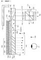
- FIG. 1 is a conceptual diagram of a display device according to the first embodiment.
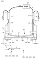
- FIG. 2 is a schematic view of the display device of Example 1 as viewed from above.
- 3A and 3B are a schematic view of the display device of the first embodiment as viewed from the side, and a schematic view of the optical device and the light control device in the display device of the first embodiment as viewed from the front.
- 4A and 4B are schematic cross-sectional views of the light control device schematically showing the behavior of the light control device in the display device of Example 1.
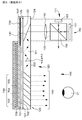
- FIG. FIG. 5 is a conceptual diagram of a display device according to the second embodiment.
- FIG. 6 is a conceptual diagram of a display device according to the third embodiment.
- FIG. 7 is a conceptual diagram of a modification of the display device according to the third embodiment.
- FIG. 8 is a conceptual diagram of a display device according to the fourth embodiment.
- FIG. 9 is a conceptual diagram of a display device according to the fifth embodiment.
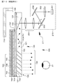
- FIG. 10 is a conceptual diagram of an image display device in the display device according to the sixth embodiment.
- FIG. 11 is a conceptual diagram of an image display device in the display device according to the seventh embodiment.
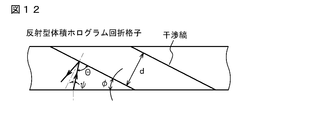
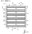
- FIG. 12 is a schematic cross-sectional view showing an enlarged part of a reflective volume hologram diffraction grating in the display device of Example 7.
- FIG. 13 is a conceptual diagram of an image display device in the display device according to the eighth embodiment.
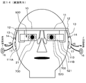
- FIG. 14 is a schematic view of the display device of Example 9 as viewed from the front.
- FIG. 15 is a schematic view of the display device of Example 9 as viewed from above.
- FIGS. 16A and 16B are a schematic view of the display device of Example 10 as viewed from above, and a schematic diagram of a circuit that controls the illuminance sensor, respectively.
- FIGS. 17A and 17B are a schematic view of the display device of Example 11 as viewed from above, and a schematic diagram of a circuit that controls the illuminance sensor, respectively.
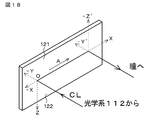
- FIG. 18 is a diagram schematically illustrating light propagation in the light guide plate included in the image display device in the display device according to the twelfth embodiment.
- FIG. 19 is a view of the state in which the display device of Example 12 is mounted on the observer's head viewed from above (however, only the image display device is shown, and the frame is not shown).
- FIG. 20 is a conceptual diagram of a state in which the display device of Example 12 is used.
- FIG. 21 is a conceptual diagram of a state in which the display device of Example 12 is used.
- FIG. 22 is a conceptual diagram of a control device constituting the display device of the twelfth embodiment.
- FIG. 23A and FIG. 23B are diagrams illustrating examples of image signals in the twelfth and thirteenth embodiments.
- 24A, 24B, and 24C are schematic diagrams illustrating a state in which images displayed by the left-eye and right-eye image display devices are shifted.
- FIG. 25B are a conceptual diagram of a format of an image signal to the image forming apparatus and a signal to which observation position information from an observer (display device) to an observation object is added, and a display device, respectively. It is a schematic diagram for demonstrating adjustment of the convergence angle corresponding to the distance to an observation target object.
- FIG. 26A and FIG. 26B are diagrams schematically showing light propagation in a light guide plate constituting the image display device and a conceptual diagram showing an arrangement state of the light guide plate and the like in the display device of Example 14.
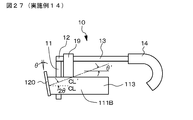
- FIG. 27 is a schematic view of the display device in Example 14 as viewed from the side.
- FIG. 28B are diagrams schematically showing light propagation in a light guide plate constituting the image display device and a conceptual diagram showing an arrangement state of the light guide plate and the like in the display device of Example 15.
- FIG. 29 is a schematic view of a conventional head-mounted display as viewed from the side in comparison with the twelfth embodiment.
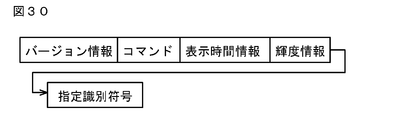
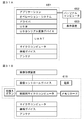
- FIG. 30 is a diagram conceptually illustrating a file structure of data constituting the data group in the sixteenth embodiment.
- 31A and 31B are a system configuration block diagram of a transmission apparatus and a system configuration block diagram of a display apparatus in Embodiment 16, respectively.
- FIG. 32 is a diagram for explaining the flow of transmission processing in the transmission apparatus according to the sixteenth embodiment.
- FIG. 33 is a diagram for explaining the flow of reception processing in the display device according to the sixteenth embodiment.
- 34A and 34B schematically show the designation identification code, the data group, the plurality of data constituting the data group, and the total display time, which are the contents displayed on the display device that constitutes the transmission device in Example 16.
- FIG. 35A and 35B are conceptual diagrams of a display device according to Example 20.
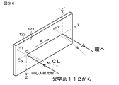
- FIG. 36 is a diagram schematically illustrating light propagation in the light guide plate included in the image display device in the display device of Example 20.
- 37A and 37B are conceptual diagrams of a display device according to Example 21.
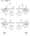
- 38A is a schematic cross-sectional view of the principle liquid lens taken along the arrow AA in FIG. 38B, and FIG.
- FIG. 38B shows the principle liquid lens along the arrow BB in FIG. 38A.
- 38C is a schematic cross-sectional view when cut
- FIG. 38C is a schematic cross-sectional view when the principle liquid lens is cut along an arrow CC in FIG. 38A.
- FIG. 39A, FIG. 39B, and FIG. 39C are schematic cross-sectional views when the principle liquid lens is cut along the arrow CC in FIG. 38A, and are diagrams for schematically explaining the behavior of the liquid lens. It is.
- FIG. 40 is a schematic cross-sectional view similar to that obtained by cutting the liquid lens according to Example 22 along the arrow AA in FIG. 38B.
- 41A, 41B, and 41C are schematic cross-sectional views when the liquid lens in Example 22 is cut along the arrow CC in FIG. 40, and the behavior of the liquid lens is schematically described. It is a figure to do.
- 42A and 42B are schematic cross-sectional views when the liquid lens in Example 22 is cut along the arrow CC in FIG. 40, and are diagrams for schematically explaining the behavior of the liquid lens. is there.
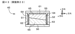
- FIG. 43 is a conceptual diagram of a liquid prism in the twenty-third embodiment.
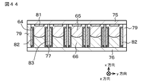
- FIG. 44 is a schematic cross-sectional view of a Fresnel lens type liquid lens for making the focal length of the optical system variable.
- FIG. 45 is a schematic plan view of a Fresnel lens type liquid lens for making the focal length of the optical system variable.
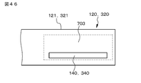
- FIG. 46 is a schematic view of the optical device and the light control device as viewed from the front according to still another modification of the display device of Example 1 or Example 7.
- FIG. 47 is a conceptual diagram of an image display device in a conventional display device.
- FIG. 48 is a conceptual diagram of an image display device in a modification of the conventional display device.
- Example 1 Display device according to first and second aspects of the present disclosure
- Example 2 Modification of Example 1
- Example 3 another modification of Example 1
- Example 4 Modification of Examples 1 to 3) 6
- Example 5 a display device according to the second aspect of the present disclosure and a modification of Example 4) 7
- Example 6 Modification of Examples 1 to 5) 8
- Example 7 another modification of Examples 1 to 5) 9.
- Example 8 another modification of Examples 1 to 5) 10.
- Example 9 (another modification of Example 1 to Example 5) 11.
- Example 10 (another modification of Examples 1 to 5) 12
- Example 11 (another modification of Examples 1 to 5) 13.
- Example 12 Display Device 1A to Display Device 1B in the Present Disclosure) 14
- Example 13 (1C display device in the present disclosure) 15.
- Example 14 (Modification of Examples 12 to 13) 16.
- Example 15 (Modification of Example 14) 17.
- Example 16 (3A display device in the present disclosure) 18.
- Example 17 (3B display device in the present disclosure) 19.
- Example 18 (3C display device in the present disclosure) 20.
- Example 19 (3D display device in the present disclosure) 21.
- Example 20 (2A display device in the present disclosure) 22.
- Example 21 (2B display device in the present disclosure) 23.
- Example 22 (2C display device in the present disclosure) 24.
- Example 23 (2D display device in the present disclosure) 25.
- Example 24 (Modification of Examples 20 to 23) 26.
- Example 25 (modification of Examples 20 to 24), others
- the projected image of the light shielding member onto the optical device includes a region of the optical device on which the light emitted from the image forming device is incident. It is preferable.
- the light shielding member is disposed on the side opposite to the side on which the image forming device of the optical device is disposed and spaced apart from the optical device. It can be set as a structure.
- the light shielding member may be made of, for example, an opaque plastic material, and such a light shielding member extends integrally from the housing of the image display device, or the image display device. It can be configured to be attached to the housing of the device, or to extend integrally from the frame, or to be attached to the frame.
- the light shielding member is disposed in a portion of the optical device opposite to the side on which the image forming device is disposed.
- the light shielding member may be arranged in the light control device.
- a light-shielding member made of an opaque material is applied to, for example, a physical vapor deposition method (PVD method) or a chemical vapor deposition method (CVD method) on the surface of the optical device.
- PVD method physical vapor deposition method
- CVD method chemical vapor deposition method
- the film may be formed based on a printing method, or may be formed by a printing method, or a film, sheet, or foil made of an opaque material (plastic material, metal material, alloy material, or the like) may be bonded.
- the projection of the light control device at the end of the light control device is projected in the projection image of the light shielding member onto the optical device.
- a configuration including an image is preferable.
- the light control device includes: A first substrate facing the optical device; a second substrate facing the first substrate; Electrodes provided on each of the first substrate and the second substrate, and A light transmission control material layer sealed between the first substrate and the second substrate;
- the second substrate can be thinner than the first substrate, and in these cases, the first substrate also serves as a component of the optical device. It can be in the form.
- the second substrate can be thinner than the first substrate.
- the light control device includes an optical shutter in which the light transmission control material layer is a liquid crystal material layer.
- the light control device can be composed of an optical shutter in which the light transmission control material layer is composed of an inorganic electroluminescent material layer.
- the light control device is not limited to these, and in addition, an optical shutter composed of an electrophoretic dispersion liquid composed of a large number of charged electrophoretic particles and a dispersion medium having a different color from the electrophoretic particles, It is generated by the redox reaction of the electrochromic material, the optical shutter by the electrodeposition method (electrodeposition / field deposition) applying the electrodeposition / dissociation phenomenon generated by the reversible redox reaction of metal (for example, silver particles). It is also possible to use an optical shutter that applies a color change of a substance, or an optical shutter that controls light transmittance by an electrowetting phenomenon.
- the material constituting the light transmission control material layer is not limited, but TN (twisted nematic) ) Type liquid crystal material and STN (super twisted nematic) type liquid crystal material.
- the material constituting the light transmission control material layer is not limited, but tungsten oxide (WO 3 ) can be illustrated.
- the optical device and the light control device in this order from the observer side. You may arrange
- a transparent glass substrate such as soda lime glass, white plate glass
- plastic polyethylene terephthalate, polyethylene naphthalate, polycarbonate, cellulose ester such as cellulose acetate, fluoropolymer such as polyvinylidene fluoride or a copolymer of polytetrafluoroethylene and hexafluoropropylene, polyoxymethylene or the like
- Polyether such as ether, polyacetal, polystyrene, polyethylene, polypropylene, methylpentene polymer, polyimide such as polyamideimide or polyetherimide, polyamide, polyethersulfone, polyphenylene sulfide, polyvinylidene fluoride, tetraacetylcellulose, brominated phenoxy, poly Examples include arylate and polysulfone.
- the plastic sheet and the plastic film may have a rigidity that does not easily bend, or may have flexibility.
- a barrier layer made of an inorganic material or an organic material may be formed on the inner surface of the substrate.
- Examples of the first electrode and the second electrode include so-called transparent electrodes.
- ITO indium tin oxide
- ITO Indium Tin Oxide
- Sn-doped In 2 O 3 crystalline ITO, and amorphous ITO
- the first electrode and the second electrode can be formed based on a physical vapor deposition method (PVD method) such as a vacuum deposition method or a sputtering method, various chemical vapor deposition methods (CVD method), various coatings, and the like.
- PVD method physical vapor deposition method
- CVD method chemical vapor deposition methods
- the electrode patterning is basically unnecessary, but can be performed by any method such as an etching method, a lift-off method, or a method using various masks when patterning is performed as desired.
- Sealing agents also called sealing agents, include thermosetting, photo-curing, moisture, such as epoxy resins, urethane resins, acrylic resins, vinyl acetate resins, ene-thiol resins, silicone resins, and modified polymer resins.
- Various resins such as a curable type and an anaerobic curable type can be used.
- the display device including the various preferable modes and configurations described above (hereinafter, these may be collectively referred to as “display device or the like of the present disclosure”).
- An illuminance sensor that measures the illuminance of the environment in which the display device is placed (sometimes referred to as an “environmental illuminance measurement sensor” for convenience); Based on the measurement result of the illuminance sensor (environmental illuminance measurement sensor), the light transmittance of the light control device can be controlled.
- the display device of the present disclosure including the above preferred form, It further includes an illuminance sensor (environmental illuminance measurement sensor) that measures the illuminance of the environment where the display device is placed, Based on the measurement result of the illuminance sensor (environmental illuminance measurement sensor), the luminance of the image formed by the image forming apparatus can be controlled.
- an illuminance sensor environmental illuminance measurement sensor
- a second illuminance sensor for measuring the illuminance based on the light transmitted through the light control device from the external environment (sometimes referred to as “transmitted light illuminance measurement sensor” for convenience); Based on the measurement result of the second illuminance sensor (transmitted light illuminance measurement sensor), the light transmittance of the light control device can be controlled.
- a second illuminance sensor (transmitted light illuminance measurement sensor) for measuring the illuminance based on the light transmitted through the light control device from the external environment; Based on the measurement result of the second illuminance sensor (transmitted light illuminance measurement sensor), the luminance of the image formed by the image forming apparatus can be controlled.
- the transmittance of the light control device is controlled based on the measurement result of the illuminance sensor (environmental illuminance measurement sensor), and is formed by the image forming apparatus based on the measurement result of the illuminance sensor (environmental illuminance measurement sensor).
- the brightness of the image is controlled
- the transmittance of the light control device is controlled based on the measurement result of the second illuminance sensor (transmitted light illuminance measurement sensor), and the measurement of the second illuminance sensor (transmitted light illuminance measurement sensor).
- the image observation state can be optimized.
- the illuminance sensor (environmental illuminance measurement sensor, transmitted light illuminance measurement sensor) may be configured from a known illuminance sensor, and the illuminance sensor may be controlled based on a known control circuit.
- the second illuminance sensor (transmitted light illuminance measurement sensor)
- the second illuminance sensor is closer to the observer than the optical device. It is desirable to be in the form of being arranged.
- the dimming device has a maximum light transmittance of 50%, and the dimming device has a minimum light transmittance of 30% or less. Can do. In addition, 1% can be mentioned as a lower limit value of the minimum light transmittance of the light control device.
- the measurement result of the illuminance sensor is referred to as a predetermined value (for convenience, the “first illuminance measurement value”) If the light transmittance of the light control device is not less than the predetermined value (for convenience, it may be referred to as “first light transmittance”) or less.
- the measurement result of the illuminance sensor is equal to or lower than a predetermined value (sometimes referred to as “second illuminance measurement value” for convenience)
- the light transmittance of the light control device is set to a predetermined value.
- the second illuminance sensor is used when the measurement result of the transmitted light illuminance measurement sensor is not the desired illuminance or when further fine adjustment of illuminance is desired.
- the light transmittance of the light control device may be adjusted while monitoring the value of the (transmitted light illuminance measurement sensor).
- 10 lux can be given as the first illuminance measurement value, and any value from 1% to 30% can be given as the first light transmittance, and the second illuminance measurement value can be given as the second illuminance measurement value.
- the second light transmittance can be any value from 51% to 99%.
- the drive voltage of the dimmer is controlled to shorten the drive time, and the dimmer of the dimmer as quickly as possible. It is preferable to increase the light transmittance.
- the light passing through the light control device is configured to be colored in a desired color by the light control device.
- the color colored by the light control device can be variable, or the color colored by the light control device can be fixed.
- a light control device colored in red, a light control device colored in green, and a light control device colored in blue may be stacked.
- the color to be colored by the light control device is not limited, but can be exemplified by brown.
- the light control device can be detachably disposed.
- the light control device is attached to, for example, a frame using a screw made of transparent plastic, or a groove is cut in the frame, and The light control device can be attached to the frame by engaging the light control device or by attaching a magnet to the frame, or a slide portion may be provided on the frame, and the light control device may be fitted into the slide portion. .
- a connector is attached to the light control device, and a control circuit (for example, included in a control device for controlling the image forming apparatus) for controlling the light transmittance of the light control device is connected via this connector and wiring.
- the light control device may be electrically connected.
- the optical device includes: (A) A light guide plate that is emitted after incident light propagates through the interior by total reflection; (B) first deflecting means for deflecting the light incident on the light guide plate so that the light incident on the light guide plate is totally reflected inside the light guide plate; and (C) a second deflecting means for deflecting the light propagated through the light guide plate by total reflection a plurality of times in order to emit the light propagated through the light guide plate by total reflection from the light guide plate; It can be set as the form provided with.
- total reflection means total internal reflection or total reflection inside the light guide plate. The same applies to the following.
- the second deflecting unit can be positioned in the projected image of the dimming device, or the dimming device can be positioned in the projected image of the second deflecting unit. it can. Further, as described above, the first deflection unit and the second deflection unit may be covered with one of the substrates (first substrate) constituting the light control device.
- the optical device is a transflective type (see-through type). Specifically, at least the portion of the optical device that faces both eyes of the observer is made semi-transmissive (see-through), and the outside scene can be viewed through these portions of the optical device.
- the display device may include one image display device or two image display devices.
- the first deflecting means reflects the light incident on the light guide plate
- the second deflecting means transmits and reflects the light propagated through the light guide plate by total reflection over a plurality of times. can do.
- the first deflecting unit functions as a reflecting mirror
- the second deflecting unit functions as a semi-transmissive mirror.
- the first deflecting means is made of, for example, a metal containing an alloy, and reflects light incident on the light guide plate (a kind of mirror) or light incident on the light guide plate.
- a diffraction grating for example, a hologram diffraction grating film
- the second deflecting means can be constituted by a multilayer laminated structure in which a large number of dielectric laminated films are laminated, a half mirror, a polarization beam splitter, or a hologram diffraction grating film.
- the first deflecting unit and the second deflecting unit are disposed inside the light guide plate (incorporated inside the light guide plate), but in the first deflecting unit, the parallel light incident on the light guide plate is provided.
- the parallel light incident on the light guide plate is reflected or diffracted so that the light is totally reflected inside the light guide plate.
- the second deflecting means the parallel light propagated by total reflection inside the light guide plate is reflected or diffracted multiple times and emitted from the light guide plate in the state of parallel light.
- the first deflecting means diffracts the light incident on the light guide plate
- the second deflecting means diffracts the light propagating through the light guide plate by total reflection over a plurality of times.
- the first deflecting means and the second deflecting means can be formed of a diffraction grating element.
- the diffraction grating element is composed of a reflection type diffraction grating element, or alternatively, a transmission type diffraction grating.
- one diffraction grating element can be a reflection type diffraction grating element
- the other diffraction grating element can be a transmission type diffraction grating element.
- the reflective diffraction grating element is a reflective volume hologram diffraction grating.
- the first deflecting means composed of the reflective volume hologram diffraction grating is referred to as a “first diffraction grating member” for convenience
- the second deflecting means composed of the reflective volume hologram diffraction grating is referred to as “second diffraction grating member” for convenience.
- the image display device can perform monochromatic (for example, green) image display.
- a structure in which diffraction grating layers are stacked may be employed. Each diffraction grating layer is formed with interference fringes corresponding to one type of wavelength band (or wavelength).
- P is applied to the first diffraction grating member or the second diffraction grating member formed of one diffraction grating layer. It can also be set as the structure in which the kind of interference fringe is formed.
- the angle of view can be divided into three equal parts, and the first diffraction grating member or the second diffraction grating member can be configured by laminating diffraction grating layers corresponding to each angle of view.
- a first diffraction grating member constituted by a diffraction grating layer composed of a reflective volume hologram diffraction grating that diffracts and reflects light having a red wavelength band (or wavelength) on the first light guide plate and the second light guide plate.
- a first diffraction grating member comprising a diffraction grating layer comprising a reflective volume hologram diffraction grating, wherein a diffraction grating member is disposed and the second light guide plate diffracts and reflects light having a green wavelength band (or wavelength);
- a first diffraction grating composed of a diffraction grating layer comprising a reflective volume hologram diffraction grating which has a second diffraction grating member and diffracts and reflects light having a blue wavelength band (or wavelength) on the third light guide plate.
- a structure in which a member and a second diffraction grating member are arranged and the first light guide plate, the second light guide plate, and the third light guide plate are stacked with a gap may be adopted.
- the diffraction efficiency increases when the light having each wavelength band (or wavelength) is diffracted and reflected by the first diffraction grating member or the second diffraction grating member, and the diffraction acceptance angle is increased. Increase and optimization of the diffraction angle can be achieved. It is preferable to arrange a protective member so that the reflective volume hologram diffraction grating does not directly contact the atmosphere.
- Examples of materials constituting the first diffraction grating member and the second diffraction grating member include photopolymer materials.
- the constituent materials and basic structure of the first diffraction grating member and the second diffraction grating member made of the reflective volume hologram diffraction grating may be the same as those of the conventional reflective volume hologram diffraction grating.
- the reflection type volume hologram diffraction grating means a hologram diffraction grating that diffracts and reflects only + 1st order diffracted light. Interference fringes are formed on the diffraction grating member from the inside to the surface, and the method for forming the interference fringes itself may be the same as the conventional forming method.
- a member constituting the diffraction grating member is irradiated with object light from a first predetermined direction on one side to a member constituting the diffraction grating member (for example, photopolymer material), and at the same time Is irradiated with reference light from a second predetermined direction on the other side, and interference fringes formed by the object light and the reference light may be recorded inside the member constituting the diffraction grating member.
- the first predetermined direction, the second predetermined direction, the wavelength of the object light and the reference light, the desired pitch of the interference fringes on the surface of the diffraction grating member, the desired inclination angle of the interference fringes ( Slant angle) can be obtained.
- the inclination angle of the interference fringes means an angle formed between the surface of the diffraction grating member (or the diffraction grating layer) and the interference fringes.
- the first diffraction grating member and the second diffraction grating member are formed of a laminated structure of P-layer diffraction grating layers made of a reflective volume hologram diffraction grating, such a diffraction grating layer is laminated with a P-layer diffraction grating.
- the P diffraction grating layer may be laminated (adhered) using, for example, an ultraviolet curable adhesive.
- the photopolymer material having adhesiveness is sequentially attached thereon to produce a diffraction grating layer, whereby the P layer A diffraction grating layer may be produced.
- the optical device may be configured to include a semi-transmissive mirror that receives the light emitted from the image forming device and emits the light toward the observer's pupil. it can.
- the light emitted from the image forming apparatus may be structured to propagate in the air and enter the semi-transmissive mirror.
- a transparent member such as a glass plate or a plastic plate (specifically, described later)
- a structure may be adopted in which the light propagates through the inside of a member made of the same material as the material constituting the light guide plate and enters the semi-transmissive mirror.
- the transflective mirror may be attached to the image forming apparatus via this transparent member, or the transflective mirror may be attached to the image forming apparatus via a member different from the transparent member.
- the image forming apparatus may have a plurality of pixels arranged in a two-dimensional matrix. Note that such a configuration of the image forming apparatus is referred to as an “image forming apparatus having a first configuration” for convenience.
- an image forming apparatus having the first configuration for example, an image forming apparatus including a reflective spatial light modulator and a light source; an image forming apparatus including a transmissive spatial light modulator and a light source; and organic EL (Electro-Luminescence)
- An image forming apparatus composed of a light emitting element such as an inorganic EL or a light emitting diode (LED) can be given.
- an image forming apparatus composed of a reflective spatial light modulator and a light source is preferable.
- the spatial light modulator examples include a light valve, for example, a transmissive or reflective liquid crystal display device such as LCOS (Liquid Crystal On On Silicon), a digital micromirror device (DMD), and a light emitting element as a light source. be able to.
- the reflective spatial light modulator reflects a part of light from the liquid crystal display device and the light source to the liquid crystal display device, and passes a part of the light reflected by the liquid crystal display device.
- a polarization beam splitter that leads to the optical system can be used.
- Examples of the light emitting element that constitutes the light source include a red light emitting element, a green light emitting element, a blue light emitting element, and a white light emitting element, or red light emitted from the red light emitting element, the green light emitting element, and the blue light emitting element.
- white light may be obtained by mixing green light and blue light with a light pipe and performing luminance uniformity.
- Examples of the light emitting element include a semiconductor laser element, a solid state laser, and an LED.
- the number of pixels may be determined based on specifications required for the image display device. Specific values of the number of pixels are 320 ⁇ 240, 432 ⁇ 240, 640 ⁇ 480, 1024 ⁇ 768, 1920 ⁇ 1080, and the like. Can be illustrated.
- the image forming apparatus may include a light source and a scanning unit that scans the parallel light emitted from the light source. it can. Note that such a configuration of the image forming apparatus is referred to as an “image forming apparatus having a second configuration” for convenience.
- Examples of the light source in the image forming apparatus having the second configuration include a light emitting element, and specifically include a red light emitting element, a green light emitting element, a blue light emitting element, and a white light emitting element, or a red light emitting element.
- White light may be obtained by mixing red light, green light, and blue light emitted from the light-emitting element, green light-emitting element, and blue light-emitting element, and using a light pipe for color mixing and luminance equalization.
- Examples of the light emitting element include a semiconductor laser element, a solid state laser, and an LED.
- the number of pixels (virtual pixels) in the image forming apparatus having the second configuration may also be determined based on specifications required for the image display apparatus.
- 320 * 240, 432 * 240, 640 * 480, 1024 * 768, 1920 * 1080 etc. can be illustrated.
- the scanning unit include a MEMS (Micro Electro Mechanical Systems) or a galvano mirror that performs micro scanning that can rotate in a two-dimensional direction.
- an optical system an optical system in which outgoing light is parallel light, which may be referred to as “parallel light outgoing optical system”
- collimated optical system or relay optical system makes a plurality of parallel lights incident on the light guide plate.
- Such a request for the parallel light is that these lights are directed to the light guide plate. This is based on the fact that the light wavefront information at the time of incidence needs to be preserved even after being emitted from the light guide plate via the first deflecting means and the second deflecting means.
- the light emitting part of the image forming apparatus may be positioned at the position (position) of the focal length in the parallel light emitting optical system, for example. .
- the parallel light emission optical system has a function of converting pixel position information into angle information in the optical system of the optical device.
- an optical system having a positive optical power as a whole which is a single lens or a combination of a convex lens, a concave lens, a free-form surface prism, and a hologram lens, can be exemplified.
- a light shielding portion having an opening may be arranged so that undesired light is emitted from the parallel light emitting optical system and does not enter the light guide plate.
- the light guide plate has two parallel surfaces (a first surface and a second surface) extending in parallel with the axis (X axis) of the light guide plate.
- the light guide plate entrance surface When the surface of the light guide plate on which light is incident is the light guide plate entrance surface, and the surface of the light guide plate on which light is emitted is the light guide plate exit surface, the light guide plate entrance surface and the light guide plate exit surface are configured by the first surface.
- the light guide plate entrance surface may be configured by the first surface
- the light guide plate exit surface may be configured by the second surface.
- the light guide plate As a material constituting the light guide plate, glass containing optical glass such as quartz glass or BK7, or plastic material (for example, PMMA, polycarbonate resin, acrylic resin, amorphous polypropylene resin, styrene resin containing AS resin) ).
- glass containing optical glass such as quartz glass or BK7
- plastic material for example, PMMA, polycarbonate resin, acrylic resin, amorphous polypropylene resin, styrene resin containing AS resin.
- the shape of the light guide plate is not limited to a flat plate, and may have a curved shape.
- the frame includes a front part disposed in front of the observer and two temple parts rotatably attached to both ends of the front part via hinges. Can do. A modern portion is attached to the tip of each temple portion.
- the image display device is attached to the frame, specifically, for example, the image forming device may be attached to the temple portion.
- the front part and the two temple parts can be integrated. That is, when the entire display device or the like of the present disclosure is viewed, the frame has substantially the same structure as normal glasses.
- the material constituting the frame including the pad portion can be made of the same material as that constituting normal glasses such as metal, alloy, plastic, and a combination thereof.
- the nose pad can be set as the structure by which the nose pad is attached to the front part. That is, when the entire display device or the like of the present disclosure is viewed, the assembly of the frame and the nose pad has substantially the same structure as normal glasses except that there is no rim.
- the nose pad can also have a known configuration and structure.
- each image forming apparatus includes a headphone section, and the headphone section wiring from each image forming apparatus is routed from the tip of the modern section to the headphone section via the temple section and the interior of the modern section. It can also be made into the extended form.
- the headphone unit include an inner ear type headphone unit and a canal type headphone unit.
- the headphone part wiring preferably has a form extending from the tip part of the modern part to the headphone part so as to wrap around the back side of the auricle (ear shell). Moreover, it can also be set as the form by which the imaging device was attached to the center part of the front part.
- the imaging device is configured by a solid-state imaging device and a lens made up of, for example, a CCD or a CMOS sensor.
- the wiring from the imaging device may be connected to, for example, one image display device (or image forming device) via the front portion, and is further included in the wiring extending from the image display device (or image forming device). That's fine.
- the display device includes two image display devices for the right eye and the left eye attached to the frame, an image of the outside by the observer and an image such as a caption displayed on the image display device
- an image is superimposed, there is a large difference between the convergence angle for the external image (real image) (the principal ray crossing angle in the horizontal plane; the same applies hereinafter) and the convergence angle for the image (virtual image displayed on the image display device).
- the convergence angle for the external image real image
- the convergence angle for the image virtual image displayed on the image display device
- cone cells that can take in information with high resolution are distributed in the fovea at high density.
- the visual acuity around the retina where rod cells are distributed is known to be lower than the central visual acuity. Therefore, the visual acuity of the portion being watched is high, but the peripheral visual acuity is low.
- an image such as subtitles
- the image of the outside world to be watched and the display position of the image are far apart, it is difficult to visually recognize the image. It becomes difficult to see the image of the outside world. For example, if the position of a performer who emits a line in a play and the display position of a subtitle that displays the line are superimposed at a large distance, such a problem occurs.
- a display device including two image display devices for the right eye and the left eye attached to the frame
- the convergence angle may be adjusted depending on the observation position of the observer by controlling the image signal to the image forming apparatus constituting at least one of the image display apparatuses.
- a display device is referred to as a “1A display device in the present disclosure” for convenience.
- the convergence angle is adjusted depending on the observation position of the observer.
- the angle of convergence corresponding to the distance from the display device to the observation object is adjusted, whereby the distance between the observation object and the observer (audience) is displayed by the image display device.
- the virtual image distances of the images being made can be equal, or they can be as equal as possible. Therefore, the observer (audience) looking at the observation object can naturally see (observe) the image displayed by the image display device without changing or changing the focal point. Fatigue is difficult to occur. In other words, as long as such a state is achieved, it can be said that the distance between the observation object and the observer (audience) is equal to the virtual image distance of the image displayed by the image display device.
- a display including two image display devices for the right eye and the left eye attached to the frame In the apparatus, the position of the image displayed on the optical device constituting the at least one image display device is controlled by controlling the image signal to the image forming device constituting the at least one image display device. Adjust depending on. Note that such a display device is referred to as a “1B display device in the present disclosure” for convenience.
- the position of the image displayed on the optical device is adjusted depending on the observation position of the observer, so that the observer sees the image superimposed on the image of the outside world.
- the external image to be watched and the display position of the image are not greatly separated, and the image can be easily visually recognized.
- a display device that can suppress waste of energy
- image formation in the image forming apparatus is stopped after a predetermined time has elapsed since the input of the image signal to the image forming apparatus.
- a display device is referred to as a “1C display device in the present disclosure” for convenience.
- image formation in the image forming apparatus is stopped after a predetermined time has elapsed since the image signal was input to the image forming apparatus. That is, since the display device shifts to the power saving mode or the standby mode and the hibernation mode after a predetermined time elapses, there is no problem of waste of power in the display device.
- a display device including two image display devices for the right eye and the left eye attached to the frame
- Each image display device further includes an optical system (parallel light emission optical system) that converts the light emitted from the image forming device into parallel light
- At least one of the image display devices that is, an image display device for the right eye, an image display device for the left eye, or two image display devices for the right eye and the left eye, and so on
- the apparatus further comprises a moving device that relatively moves the optical axis of the image forming apparatus and the optical axis of the optical system in the horizontal direction, and depending on the observation position of the observer, The convergence angle is adjusted by relatively moving the optical axis of the optical system in the horizontal direction.
- a display device is referred to as a “second A display device in the present disclosure” for convenience.
- a display device including two image display devices for the right eye and the left eye attached to the frame
- Each image display device further includes an optical system (parallel light emission optical system) that collimates the light emitted from the image forming device, and at least one of the image display devices rotates the image forming device and the optical system.
- a rotating device that moves the image forming device and the optical system by rotating the image forming device and the optical system depending on the observation position of the observer, so that the light is emitted from the optical system and incident on the optical device.
- the incident angle of the light with respect to the optical device is changed, thereby adjusting the convergence angle.
- a display device is referred to as a “second-B display device in the present disclosure” for convenience.
- a display device including two image display devices for the right eye and the left eye attached to the frame
- the optical system constituting at least one of the image display devices includes a liquid lens, and the convergence angle is adjusted by the operation of the liquid lens depending on the observation position of the observer.
- a display device is referred to as a “second C display device in the present disclosure” for convenience.
- a display device including two image display devices for the right eye and the left eye attached to the frame
- the optical system constituting at least one of the image display apparatuses includes a liquid prism, and the convergence angle is adjusted by the operation of the liquid prism depending on the observation position of the observer.
- a display device is referred to as “a 2D display device in the present disclosure” for convenience.
- At least one of the image display devices is configured by controlling an image signal to the image forming device configuring at least one of the image display devices. It is possible to achieve any combination of left and right movement, up and down movement, and rotational movement of the image displayed in the optical device. In such movement of the image, for example, a non-display area may be secured in the optical device, and that portion may be allocated for moving the image.
- the convergence angle is further adjusted by controlling the image signal to the image forming device constituting at least one of the image display devices. It can be in the form.
- the image displayed on the optical device constituting at least one of the image display devices is moved left and right, and up and down. It can be configured to achieve any combination of movement and rotational movement. In such movement of the image, for example, a non-display area may be secured in the optical device, and that portion may be allocated for moving the image.
- the image displayed on the optical device constituting at least one of the image display devices when controlling the position of the image displayed on the optical device constituting at least one of the image display devices, and adjusting the mutual optical position of the two image display devices, specifically, The image displayed on the optical device constituting at least one of the image display devices so that the images displayed by the left-eye image display device and the right-eye image display device match at a desired virtual image distance or virtual image position. What is necessary is just to control the position. More specifically, the viewer wears the display device, and the images displayed by the left-eye image display device and the right-eye image display device are matched with each other at a desired virtual image distance or virtual image position. A display position correction signal may be added to the image signal.
- the display position correction signal may be stored in a display device (specifically, a control device provided in the display device).
- a display device specifically, a control device provided in the display device.
- observation position information in addition to the image signal to the image forming device, information on the observation position of the observer (hereinafter referred to as “observer”).
- the observation position information may be sent from the outside to the display device, or may be further provided with a position measuring means for measuring the observation position of the observer. it can.
- the observation position information of the observer is displayed in advance in addition to the image signal to the image forming device.
- the observation position information of the observer can be sent from the outside to the display device, or the position measuring means for measuring the observation position of the observer can be further provided. it can.
- the observation position information of the observer is sent from the outside to the display device
- the observation position information of the observer is displayed on the display device (specifically, a control device provided in the display device).
- the display device specifically, a control device provided in the display device.
- position measuring means for measuring the observation position of the observer specifically, as the position measuring means, a camera with an autofocus function or an imaging device (for example, infrared or ultrasonic waves on the observation object)
- a camera or an image pickup device having a passive distance measurement device, and a camera with an autofocus function A measuring device (active distance measuring device) can be mentioned.
- a button or a switch may be provided on the display device, and the distance from the display device to the observation object may be manually set.
- a form in which the observation position information of the observer is set in the display device in advance can be adopted.
- the observation position information of the observer may be given to the display device from a personal computer, for example, bar-coded seat information or theater information (hall information, theater information, etc. printed on a ticket. ), Reading the seat information and theater information included in the ticket information displayed on the mobile phone by an appropriate means / method, and giving the observation position information of the observer based on the seat information and theater information to the display device by an appropriate means. May be.
- a signal indicating an image display time in the image display device or a signal instructing to stop image formation in the image forming device is included in the image signal. It only has to be weighted.
- the predetermined time include a time for a normal person to read subtitles displayed on the image forming apparatus, or a subtitle display time determined in advance according to the length of dialogue.
- the image is further displayed after a predetermined time has elapsed since the image signal was input to the image forming apparatus. It is possible to stop the image formation in the forming apparatus. As a result, the display device can be shifted to the power saving mode or the standby and hibernation modes after a predetermined time has elapsed, so that problems such as waste of power and energy in the display device do not occur.
- the image signal to the image forming apparatus is used.
- a luminance signal of an image to be displayed on the optical device can be sent from the outside to the display device.
- the luminance signal may be transmitted from the outside to the display device wirelessly.
- the 2A display device to 2D display device in the present disclosure are displayed on the optical device by an image signal.
- the image is composed of characters.
- an image signal (sometimes referred to as “character data”) for displaying characters as an image is digitized data, and is preliminarily determined by an operator or based on processing by a computer or the like. Create it.
- the format of the character data may be appropriately selected depending on the display device or system to be used. For example, it can be text data composed of character strings, or image data using character strings as images. You can also.
- an image for example, a caption or a virtual image displayed at a certain position.
- Position of the image formed by the two optical devices image position or an image formed by the two optical devices (for example, subtitles) Or a virtual image) can be configured to change the distance (image distance) from the two optical devices over time.
- changing with time means, for example, once every 5 to 10 minutes, the position of the image in the horizontal direction is changed to, for example, +2 pixels or ⁇ 1 pixel in the image forming apparatus, for example, 1 minute to It means to return to the original state after changing for 3 minutes.
- the viewer wears the display device, and an image displayed by the left-eye image display device and the right-eye image display device is a desired one.
- a display position correction signal may be added to the original image signal so that the virtual image distance or virtual image position matches.
- the display position correction signal may be stored in a display device (specifically, a control device included in the display device), or an image signal obtained by weighting the display position correction signal to the original image signal is displayed on the display device. May be sent to In the 1A display device to the 1C display device and the 2A display device to the 2D display device according to the present disclosure including the various preferable forms described above, the image signal is wirelessly transmitted to the display device. It can be made to come.
- the image signal is received by the control device, and processing for image display is performed by the control device.
- the image signal may be stored in a display device (control device).
- a display position correction signal may be sent to the display device.
- the position of the image displayed on the optical device constituting at least one of the image display devices is controlled, thereby adjusting the mutual optical position of the two image display devices.
- Position of the image displayed on the optical device constituting at least one of the image display devices so that the images displayed by the image display device for the eye and the image display device for the right eye match at a desired virtual image distance or virtual image position Can be controlled.
- the control device (control circuit, control means) can be composed of a known circuit.
- the 2A display device to the 2D display device in the present disclosure include:
- the control device provided in the display device has a storage unit, and the storage unit stores a data group composed of a plurality of image signals (for example, character data) for displaying an image.
- Each image signal constituting the data group is attached with a data identification code
- the designated identification code and display time information are sent from the outside to the control device at predetermined time intervals,
- an image signal in which the transmitted designated identification code and the data identification code match is read from the storage means, and an image based on the image signal is displayed on the display device for a time corresponding to the transmitted display time information.
- the “time corresponding to the display time information” may be a “predetermined time” in the 1C display device according to the present disclosure. Such a configuration may be referred to as a “3A display device in the present disclosure” for convenience.
- the designated identification code and the display time information are sent from the outside to the control device at predetermined time intervals, and the designated identification code and data sent from the control device are sent to the control device.
- An image signal with a matching identification code is read from the storage means, and an image based on the image signal is displayed on the image forming apparatus for a time corresponding to the transmitted display time information. Therefore, even if reception of the designated identification code and / or display time information sent from the outside fails for some reason in the control device, try to receive the designated identification code and display time information again or repeatedly. Therefore, the designated identification code and the display time information can be reliably received.
- the 2A display device to the 2D display device in the present disclosure include:
- the control device provided in the display device has a storage unit, and the storage unit stores a data group composed of a plurality of image signals (for example, character data) for displaying an image.
- Each image signal constituting the data group is attached with a data identification code,
- Each image signal consists of multiple different sizes and display data with different display sizes.
- a designated identification code is sent from the outside to the control device,
- one of the different sizes / display data is selected from the plurality of different sizes / display data depending on the distance between the object to be observed and the display device among the image signals having the same designated identification code and data identification code.
- the size / display data may be read from the storage unit, and an image based on the one different size / display data may be displayed on the display device. Note that this configuration may be referred to as “the 3B display device in the present disclosure” for convenience.
- the distance between the observation object and the display device in the image signal in which the designated identification code and the data identification code transmitted are the same.
- one different size / display data is read from the storage means, and an image based on the one different size / display data is displayed on the image forming apparatus. An imbalance is unlikely to occur between the size visually observed and the size of the image.
- the 2A display device to the 2D display device in the present disclosure include:
- the control device provided in the display device has a storage unit, and the storage unit stores a data group composed of a plurality of image signals (for example, character data) for displaying an image.
- Each image signal constituting the data group is attached with a data identification code,
- Each image signal consists of multiple different languages and display data with different display languages.
- a designated identification code is sent from the outside to the control device,
- one different language / display data is read from a plurality of different languages / display data from a plurality of different languages / display data out of the image signal in which the designated identification code and the data identification code coincide with each other.
- An image based on the display data may be displayed on the display device. Note that this configuration may be referred to as “the 3C display device in the present disclosure” for convenience.
- a method of selecting what language as the display language for example, a method of providing a button or a switch in the control device and manually selecting the display language can be cited.
- the language / display data is read from the storage means, and the image based on the one different language / display data is displayed on the image forming apparatus, so that the image can be easily displayed in the language used by the observer (audience). .
- the 2A display device to the 2D display device in the present disclosure include:
- the control device provided in the display device has a storage unit, and the storage unit stores a data group composed of a plurality of image signals (for example, character data) for displaying an image.
- Each image signal constituting the data group is attached with a data identification code
- a designated identification code is sent from the outside to the control device.
- congestion is performed by reading out an image signal in which the designated identification code and the data identification code that have been sent coincide with each other and performing data processing depending on the distance between the observation object and the display device.
- An image based on the image signal (image signal on which data processing has been performed) can be displayed on the display device in a state where the corner is controlled.
- Such a configuration may be referred to as a “3D display device in the present disclosure” for convenience.
- image processing may be performed on the image signal to the image forming device constituting at least one of the image display devices.
- the angle of convergence corresponding to the distance from the display device to the observation object is adjusted, and thereby, the observation object and the observer (audience) are adjusted.
- the distance between and the virtual image distance of the image displayed by the image display device can be made equal, or they can be made as equal as possible.
- the image displayed by the image display device can be naturally viewed (observed) without changing or changing the focus.
- the 2A to 2D display devices including the various preferable forms and configurations described above, depending on the observation position of the observer and between the observation object and the display device Depending on the distance, the size of the display screen (image display area) displayed on the optical device, the angle of view of the display screen (image display area), and the resolution of the display screen may be changed. Note that this configuration may be referred to as a “second E display device in the present disclosure” for convenience.
- the control device itself may have a well-known circuit configuration, and storage means
- the storage unit itself may be a well-known storage unit, for example, a memory card.
- the designation identification code and the display time information can be wirelessly transmitted from the transmission device, and the transmission device further includes a display device.
- the display device includes a designation identification code and a data group. The total display time of each image signal or each display data can be displayed.
- the transmission device itself for sending the designated identification code to the control device may be a known transmission device, and the display device provided in the transmission device may be a known display device.
- the moving device is operated in the 2A display device in the present disclosure
- the rotating device is operated in the 2B display device in the present disclosure
- the 2C display in the present disclosure is operated.
- the liquid lens is operated, and in the 2D display apparatus according to the present disclosure, the liquid prism is operated.
- the moving device relatively moves the optical axis of the image forming apparatus and the optical axis of the optical system in the horizontal direction (X-axis direction).
- X horizontal direction
- the positions of the optical axis of the image forming apparatus and the optical axis of the optical system in the other image display apparatus are set in the horizontal direction (X (Axial direction) can be mentioned.
- a form in which the positions of the optical axis of the image forming apparatus and the optical axis of the optical system in both of the image display apparatuses are relatively moved in the horizontal direction (X-axis direction) can be given.
- the incident angle of the parallel light emitted from the optical system and incident on the optical device (the angle formed by the central incident light beam and the YZ plane described later, hereinafter referred to as “YZ plane / incident”).
- YZ plane / incident the angle formed by the central incident light beam and the YZ plane described later, hereinafter referred to as “YZ plane / incident”.
- the image forming apparatus and the optical system are rotated by the rotating device. Specifically, the optical axis and the optical system of the image forming apparatus in each of the two image display devices are rotated. While fixing the positional relationship with the optical axis, at least one of the image display devices may be rotated by operating a piezoelectric element, a motor, or an ultrasonic motor with the Z axis as a rotation axis. Even in such a form, the YZ plane and the incident angle of the parallel light emitted from the optical system and incident on the optical device are changed.
- the liquid lens is operated.
- the liquid lens constituting the optical system may be a known liquid lens using an electrowetting phenomenon.
- the optical axis of the optical system can be moved in the horizontal direction (X-axis direction) while maintaining the relationship between the optical axis of the optical system and the Y-axis constant, or the YZ plane.
- the angle of the optical axis of the optical system with respect to can be changed. Even in such a form, the YZ plane and the incident angle of the parallel light emitted from the optical system and incident on the optical device are changed.
- the liquid prism is operated.
- the liquid prism constituting a part of the optical system may be configured by a known liquid prism using an electrowetting phenomenon.
- the angle of the optical axis of the optical system with respect to the YZ plane can be changed by the operation of the liquid prism. Even in such a form, the YZ plane and the incident angle of the parallel light emitted from the optical system and incident on the optical device are changed.
- the number of data groups is essentially arbitrary
- the number of image signals (for example, character data) constituting the data group and the number of display data constituting the image signals (character data) are also essentially arbitrary.
- the data structure of the image signal or display data can be, for example, text data composed of a character string, or image data using a character string as an image.
- the display data with different display sizes can be text data composed of character strings with different font sizes, or image data with character strings with different font sizes as images.
- the display language in the display data is essentially arbitrary.
- An image signal can be obtained by performing predetermined signal processing on the image signal or display data.
- the designated identification code and the data identification code can be any codes as long as they can identify the image signal, and examples thereof include numbers, alphabets, and combinations of numbers and alphabets.
- the designated identification code and the display time information are sent from the outside to the control device at predetermined time intervals.
- T total 10.0 seconds
- T int 0.1 seconds
- T Inf (1) 10.0 seconds.
- the control device may set a kind of flag (reception completion flag).
- the control device fails to receive the designated identification code and / or the display time information from the outside for some reason.
- T Inf (m ′) T total ⁇ (m′ ⁇ 1) ⁇ T int During this time, an image based on an image signal or one display data may be displayed on the image forming apparatus.
- a light beam that is emitted from the center of the image forming apparatus and passes through a node on the image forming apparatus side of the optical system is called a “central light beam”, and a central light beam that enters the optical device perpendicularly is called a “central incident light beam”.
- the point where the central incident light beam enters the optical device is defined as the optical device central point, passes through the optical device central point, passes through the axis parallel to the axial direction of the optical device, the X axis, and passes through the optical device central point.
- the axis line that coincides with the normal line is defined as the Y axis.
- the horizontal direction in the display device or the like of the present disclosure is a direction parallel to the X axis, and may be hereinafter referred to as “X axis direction”.
- the optical system is disposed between the image forming apparatus and the optical apparatus, and the light emitted from the image forming apparatus is converted into parallel light. Then, the light beam converted into parallel light by the optical system is incident on the optical device, guided, and emitted. Further, the center point of the first deflecting means is referred to as “optical device center point”.
- the 1A display device to the 1C display device and the 2A display device to the 2D display device according to the present disclosure are not limited in the image display device, but the central incident light beam is not limited to the XY plane. And an angle ( ⁇ ) other than 0 degrees can be crossed, thereby reducing restrictions on the mounting angle of the image display device when the image display device is mounted on the mounting portion of the spectacle-shaped frame, and a high design A degree of freedom can be obtained.
- the center incident light beam is preferably included in the YZ plane from the viewpoint of handling, setting, and ease of mounting of the image display device.
- the optical axis of the optical system is included in the YZ plane and can intersect with the XY plane at an angle other than 0 degrees, or the optical axis of the optical system is parallel to the YZ plane.
- the image forming apparatus can be configured to pass through a position that is parallel to the XY plane and deviated from the center of the image forming apparatus.
- the angle ⁇ at which the central incident light beam intersects the XY plane can be an elevation angle. That is, it can be configured such that the central incident light beam is directed from the lower side of the XY plane toward the XY plane and collides with the XY plane.
- the XY plane preferably intersects with the vertical plane at an angle other than 0 degrees, and further, the XY plane preferably intersects with the vertical plane at an angle ⁇ ′.
- the maximum value of ⁇ ′ is not limited, but can be 5 degrees.
- the horizontal plane is a line of sight when an observer looks at an object located in a horizontal direction (for example, a horizontal object, an object at infinity, a horizon or a horizontal line) ("observer's horizontal line of sight"). ) And a plane including two pupils of an observer positioned horizontally.
- the vertical plane is a plane perpendicular to the horizontal plane.
- Incident light can be in the form of a depression.
- the depression angle with respect to the horizontal plane for example, 5 to 45 degrees can be exemplified.
- the display device and the like of the present disclosure including the various modifications described above include, for example, display of moving images and still images; display of subtitles such as movies; display of explanatory text and closed captions related to video synchronized with video; Various explanations about the objects to be observed in Kabuki, Noh, Noh, Kyogen, Opera, Music Festival, ballet, Various plays, Amusement parks, Museums, Sightseeing spots, Resorts, tourist information, etc. It can be used to display explanatory texts for explaining the background, etc., and also functions as a character display device, and various explanations during operation, operation, maintenance, disassembly, etc.
- observation objects such as various devices Display of symbols, signs, marks, marks, designs, etc .; Display of various explanations regarding observation objects such as people and articles, display of symbols, signs, marks, marks, designs, etc .; Used for displaying closed captions Rukoto can.
- observation objects such as various devices Display of symbols, signs, marks, marks, designs, etc .; Display of various explanations regarding observation objects such as people and articles, display of symbols, signs, marks, marks, designs, etc .; Used for displaying closed captions Rukoto can.
- the image signal is sent to the display device, or the designated identification code is sent to the control device, and the image is displayed on the display device.
- an imaging device is arranged on the display device, and various devices, observation objects such as people and articles are photographed by the imaging device, By analyzing the photographic content in the display device, various descriptions relating to observation objects such as various devices and people and articles prepared in advance can be displayed on the display device.
- the display device and the like of the present disclosure can be used as a stereoscopic display device.
- a polarizing plate or a polarizing film may be detachably attached to the optical device, or a polarizing plate or a polarizing film may be attached to the optical device.
- the image signal to the image forming apparatus includes not only the image signal (for example, character data) but also luminance data (luminance information) or chromaticity data (chromaticity information) related to the image to be displayed. Or, luminance data and chromaticity data can be included.
- the luminance data can be luminance data corresponding to the luminance of a predetermined region including the observation object viewed through the optical device
- the chromaticity data can be the luminance data of the predetermined region including the observation object viewed through the optical device. It can be chromaticity data corresponding to chromaticity.
- the luminance (brightness) of the displayed image can be controlled by including the luminance data regarding the image
- the chromaticity of the displayed image can be controlled by including the chromaticity data regarding the image.
- Color can be controlled
- luminance (brightness) and chromaticity (color) of a displayed image can be controlled by including luminance data and chromaticity data related to the image.
- luminance data corresponding to the luminance of a predetermined area including the observation object viewed through the image display device the luminance of the image increases as the luminance value of the predetermined area including the observation object viewed through the image display device increases.
- the value of the luminance data may be set so that the value of is high (that is, the image is displayed brighter).
- the chromaticity data corresponding to the chromaticity of the predetermined area including the observation object viewed through the image display device is displayed, the chromaticity data of the predetermined area including the observation object viewed through the image display device is displayed.
- the value of the chromaticity data may be set so that the chromaticity of the power image is approximately complementary.
- Complementary color refers to a combination of colors that are located in opposite directions in a color circle. It is also a complementary color, such as green for red, purple for yellow, orange for blue. This is a color that causes a decrease in saturation, such as white in the case of light and black in the case of an object by mixing another color with an appropriate ratio. Complementarity differs from complementarity when mixed.
- Example 1 relates to a display device according to a first aspect of the present disclosure.
- FIG. 1 shows a conceptual diagram of the image display device of Example 1
- FIG. 2 shows a schematic view of the display device of Example 1 (specifically, a head-mounted display, HMD) as viewed from above.
- FIG. 3A shows a schematic diagram viewed from the side
- FIG. 3B shows a schematic diagram of the optical device and the light control device viewed from the front, and schematically shows the behavior of the light control device in the display device of Example 1.
- 4A and 4B show schematic cross-sectional views of the light control device.
- the light shielding member is indicated by a dotted line.
- the display devices of Example 1 or Examples 2 to 11 described later are: (A) a glasses-type frame 10 mounted on the head of an observer (for example, an audience), and (B) Image display devices 100, 200, 300, 400, 500 attached to the frame 10; It has.
- the display device of the first embodiment or the second to eleventh embodiments described later is specifically a binocular type including two image display devices, but may be a single eye type including one image display device.
- the image forming apparatuses 111 and 211 display, for example, a single color image.
- the image display devices 100, 200, 300, 400, and 500 in the first embodiment or the second to eleventh embodiments described later are: (A) Image forming apparatuses 111, 211, and (B) Optical devices 120, 320, and 520 in which light emitted from the image forming apparatuses 111 and 211 is incident, guided, and emitted. It has. Furthermore, (C) Optical systems (parallel light emitting optical systems) 112, 254 that convert light emitted from the image forming apparatuses 111, 211 into parallel light, The light beams converted into parallel light by the optical systems 112 and 254 are incident on the optical devices 120, 320, and 520, guided, and emitted.
- Optical systems parallel light emitting optical systems
- the outside of the optical devices 120, 320, and 520 opposite to the side on which the image forming apparatuses 111 and 211 are disposed is external light incident from the outside.
- a light control device 700 for adjusting the amount of light is provided.
- the light control device 700 which is a kind of optical shutter uses an adhesive 707 and uses an optical device 120, 320, 520 (specifically, a protective member (protective plate for protecting the light guide plates 121, 321). ) 126, 326 or semi-transparent mirror 520).
- the light control device 700 is disposed in the region of the optical devices 120, 320, and 520 on the opposite side to the observer.
- the protective members (protective plates) 126 and 326 are bonded to the second surfaces 123 and 323 of the light guide plates 121 and 321 by adhesive members 127 and 327, respectively.
- the optical devices 120 and 320 in Example 1 or Example 2 to Example 8 and Example 10 to Example 11 described later are: (A) After the incident light propagates through the interior by total reflection, the light guide plates 121 and 321 are emitted. (B) first deflecting means 130, 330 for deflecting the light incident on the light guide plates 121, 321 so that the light incident on the light guide plates 121, 321 is totally reflected inside the light guide plates 121, 321; as well as, (C) In order to emit from the light guide plates 121 and 321, the light propagated through total reflection in the light guide plates 121 and 321, the light propagated through total reflection in the light guide plates 121 and 321 is deflected multiple times. Second deflection means 140, 340, It has.
- deviation means 140,340 is located in the projection image of the light modulation apparatus 700.
- FIG. Furthermore, the first deflecting means 130 and 330 and the second deflecting means 140 and 340 are covered with one of the substrates constituting the light control device 700 (first substrate 701).
- the optical devices 120 and 320 are a see-through type (semi-transmissive type).
- the first deflection unit 130 and the second deflection unit 140 are disposed inside the light guide plate 121.
- the first deflecting unit 130 reflects the light incident on the light guide plate 121
- the second deflecting unit 140 transmits and reflects the light propagated through the light guide plate 121 by total reflection over a plurality of times.
- the first deflecting unit 130 functions as a reflecting mirror
- the second deflecting unit 140 functions as a semi-transmissive mirror.
- the first deflecting means 130 provided inside the light guide plate 121 is made of aluminum (Al), and is composed of a light reflecting film (a kind of mirror) that reflects light incident on the light guide plate 121. Has been.
- the second deflecting means 140 provided inside the light guide plate 121 is composed of a multilayer laminated structure in which a large number of dielectric laminated films are laminated.
- the dielectric laminated film is composed of, for example, a TiO 2 film as a high dielectric constant material and an SiO 2 film as a low dielectric constant material.
- a multilayer laminated structure in which a large number of dielectric laminated films are laminated is disclosed in JP-T-2005-521099. In the drawing, a six-layer dielectric laminated film is shown, but the present invention is not limited to this.
- a thin piece made of the same material as that constituting the light guide plate 121 is sandwiched between the dielectric laminated film and the dielectric laminated film.
- the parallel light incident on the light guide plate 121 is reflected (or diffracted) so that the parallel light incident on the light guide plate 121 is totally reflected inside the light guide plate 121.
- the parallel light propagating through the light guide plate 121 by total reflection is reflected (or diffracted) a plurality of times, and in the state of the parallel light from the light guide plate 121, the observer's pupil 21 is reflected. It is emitted toward
- the first deflecting unit 130 cuts a portion 124 of the light guide plate 121 where the first deflecting unit 130 is provided, thereby providing the light guide plate 121 with an inclined surface on which the first deflecting unit 130 is to be formed, and vacuuming the light reflecting film on the inclined surface. After vapor deposition, the cut out portion 124 of the light guide plate 121 may be bonded to the first deflecting means 130.
- the second deflecting unit 140 is formed by laminating a large number of the same material (for example, glass) as that constituting the light guide plate 121 and a dielectric laminated film (for example, it can be formed by a vacuum deposition method).
- a multilayer laminated structure is produced, and a portion 125 of the light guide plate 121 where the second deflecting means 140 is provided is cut out to form a slope, and the multilayer laminated structure is bonded to the slope and polished to adjust the outer shape. That's fine.
- the optical device 120 in which the first deflection unit 130 and the second deflection unit 140 are provided inside the light guide plate 121 can be obtained.
- the light guide plates 121 and 321 made of optical glass or plastic material are caused by total internal reflection of the light guide plates 121 and 321. It has two parallel surfaces (first surface 122, 322 and second surface 123, 323) extending parallel to the light propagation direction (X-axis). The first surfaces 122 and 322 and the second surfaces 123 and 323 are opposed to each other. Then, parallel light enters from the first surfaces 122 and 322 corresponding to the light incident surface, propagates through the interior by total reflection, and then exits from the first surfaces 122 and 322 corresponding to the light emitting surface.
- the present invention is not limited to this, and the light incident surface may be configured by the second surfaces 123 and 323, and the light output surface may be configured by the first surfaces 122 and 322.
- the image forming apparatus 111 is an image forming apparatus having a first configuration, and includes a plurality of pixels arranged in a two-dimensional matrix. Specifically, the image forming apparatus 111 includes a reflective spatial light modulator 150 and a light source 153 including a light emitting diode that emits white light. Each image forming apparatus 111 as a whole is housed in a housing 113 (indicated by a one-dot chain line in FIG. 1), and the housing 113 is provided with an opening (not shown). Then, light is emitted from an optical system (parallel light emitting optical system, collimating optical system) 112.
- an optical system parallel light emitting optical system, collimating optical system
- the reflective spatial light modulator 150 reflects part of the light from the liquid crystal display device (LCD) 151 composed of LCOS as a light valve and the light source 153 and leads it to the liquid crystal display device 151, and the liquid crystal
- the polarizing beam splitter 152 is configured to pass a part of the light reflected by the display device 151 and guide the light to the optical system 112.
- the liquid crystal display device 151 includes a plurality of (for example, 640 ⁇ 480) pixels (liquid crystal cells) arranged in a two-dimensional matrix.
- the polarization beam splitter 152 has a known configuration and structure. Unpolarized light emitted from the light source 153 collides with the polarization beam splitter 152.
- the P-polarized component passes and is emitted out of the system.
- the S-polarized component is reflected by the polarization beam splitter 152, enters the liquid crystal display device 151, is reflected inside the liquid crystal display device 151, and is emitted from the liquid crystal display device 151.
- the light emitted from the liquid crystal display device 151 the light emitted from the pixel displaying “white” contains a lot of P-polarized components, and the light emitted from the pixel displaying “black” is S-polarized light. Contains many ingredients.
- the P-polarized component passes through the polarization beam splitter 152 and is guided to the optical system 112.
- the S-polarized component is reflected by the polarization beam splitter 152 and returned to the light source 153.
- the optical system 112 is composed of, for example, a convex lens, and the image forming apparatus 111 (more specifically, the liquid crystal display device 151) is disposed at a focal position (position) in the optical system 112 in order to generate parallel light. Has been.
- the frame 10 includes a front portion 11 disposed in front of the observer, two temple portions 13 rotatably attached to both ends of the front portion 11 via hinges 12, and tip portions of the temple portions 13. It consists of a modern part 14 (also called tip cell, ear pad, ear pad) attached. A nose pad (not shown) is attached. That is, the assembly of the frame 10 and the nose pad basically has substantially the same structure as normal glasses. Furthermore, each housing 113 is detachably attached to the temple portion 13 by an attachment member 19.
- the frame 10 is made of metal or plastic. Each housing 113 may be attached to the temple portion 13 by the attachment member 19 so that it cannot be attached to and detached from the temple portion 13.
- each housing 113 may be detachably attached to the temple part of the frame of the glasses owned by the observer by the attachment member 19.
- Each housing 113 may be attached to the outside of the temple portion 13 or may be attached to the inside of the temple portion 13.
- a wiring (a signal line, a power supply line, etc.) 15 extending from one image forming apparatus 111A extends from the distal end portion of the modern portion 14 to the outside via the temple portion 13 and the modern portion 14, and is controlled. It is connected to a device (control circuit, control means) 18.
- each of the image forming apparatuses 111A and 111B includes a headphone unit 16, and a headphone unit wiring 17 extending from each of the image forming devices 111A and 111B is provided inside the temple unit 13 and the modern unit 14.
- the modern part 14 extends from the front end part to the headphone part 16.
- the headphone part wiring 17 extends from the tip part of the modern part 14 to the headphone part 16 so as to wrap around the back side of the auricle (ear shell).
- the light control device 700 includes an optical shutter in which the light transmission control material layer 705 is a liquid crystal material layer. That is, the light control device 700 is A transparent first substrate 701 facing the optical device 120, and a transparent second substrate 703 facing the first substrate 701, Electrodes 702 and 704 provided on the first substrate 701 and the second substrate 703, and A light transmission control material layer 705 sealed between the first substrate 701 and the second substrate 703; It is composed of Here, the first substrate 701 and the second substrate 703 are made of a plastic material.
- the first electrode 702 and the second electrode 704 are made of a transparent electrode made of indium-tin composite oxide (ITO), and are formed based on a combination of a PVD method such as a sputtering method and a lift-off method.
- the light transmission control material layer 705 is specifically composed of a liquid crystal material layer made of a TN (twisted nematic) type liquid crystal material.
- the first electrode 702 and the second electrode 704 are not patterned and are so-called solid electrodes.
- the first electrode 702 and the second electrode 704 are connected to the control device 18 via connectors and wiring not shown.
- the outer edges of the two substrates 701 and 703 are sealed with a sealant 706.
- the first substrate 701 and the protection member 126 (which protects the light guide plate 121) of the light control device 700 are bonded by an adhesive 707.
- the polarizing film is bonded together on the outer surface of the 1st board
- illustration of these polarizing films was abbreviate
- the first substrate 701 of the light control device 700 has a length shorter than that of the light guide plate 121, and the first substrate 701 of the light control device 700 is fixed to the protective member 126 with an adhesive 707.
- the adhesive 707 is disposed on the outer edge portion of the first substrate 701. The same applies to Examples 1 to 4 described below. Note that the optical device 120 and the light control device 700 are arranged in this order from the observer side.
- the area of the optical device 120 to which the light emitted from the image forming apparatuses 111A and 111B is incident specifically, the area where the first deflecting unit 130 is provided, A light shielding member 710 that shields external light from entering the optical device 120 is disposed.
- the area of the optical device 120 into which the light emitted from the image forming apparatuses 111A and 111B is incident is included in the projection image 710 onto the optical device 120.
- the projection image of the light shielding member 710 onto the optical device 120 includes a projection image onto the optical device 120 at the end of the light control device 700.
- the light shielding member 710 is disposed apart from the optical device 120 on the side opposite to the side where the image forming apparatuses 111A and 111B of the optical device 120 are disposed.
- the light shielding member 710 is made of, for example, an opaque plastic material, and the light shielding member 710 extends integrally from the housing 113 of the image display devices 111A and 111B, or alternatively, the housing 113 of the image display devices 111A and 111B. Or alternatively extends integrally from the frame 10 or alternatively attached to the frame 10. In the illustrated example, the light shielding member 710 extends integrally from the housing 113 of the image display apparatuses 111A and 111B.
- the light transmittance of the light control device 700 can be controlled by the voltage applied to the first electrode 702 and the second electrode 704. Specifically, for example, when a voltage is applied to the first electrode 702 while the second electrode 704 is grounded, the liquid crystal alignment state in the liquid crystal material layer constituting the light transmission control material layer 705 changes, and the liquid crystal material The light transmittance of the layer changes. (See FIGS. 4A and 4B).
- the voltage applied to the first electrode 702 and the second electrode 704 can be performed by an observer operating a control knob provided in the control device 18. In other words, the observer may observe the images from the optical devices 120 and 320 and adjust the light transmittance of the light control device 700 to improve the contrast of the images.
- the maximum light transmittance of the light control device 700 is 50% and the minimum light transmittance is 30% or less (preferably 1% or more and 30% or less). understood.
- a light-shielding member that shields external light from entering the optical device is disposed in a region of the optical device where light emitted from the image forming apparatus is incident. Therefore, even if the incident light quantity of the external light changes due to the operation of the light control device, in the first place, the area of the optical device into which the light emitted from the image forming apparatus is incident, specifically, the first deflecting unit 130. Since no external light is incident, undesired stray light or the like is generated and image display quality in the display device is not deteriorated.
- Example 2 is a modification of Example 1.
- the light shielding member 720 is provided on the optical device 120 on the side opposite to the side where the image forming apparatuses 111 ⁇ / b> A and 111 ⁇ / b> B are arranged. Arranged in the part.
- the opaque member 720 can be formed by printing opaque ink on the optical device 120 (specifically, the inner surface of the protective member 126).
- the display device of the second embodiment has the same configuration and structure as the display device of the first embodiment, and thus detailed description thereof is omitted.
- the light shielding member 720 according to the second embodiment and the light shielding member 710 according to the first embodiment may be combined.
- the light shielding member 720 may be formed on the outer surface of the protection member 126.
- Example 3 is also a modification of Example 1.
- the light shielding member 730 is arranged in the light control device 700.
- the light shielding member 730 can be formed by printing opaque ink on the light control device 700.
- the light shielding member 730 is formed on the outer surface of the first substrate 701 of the light control device 700, and in the example shown in FIG. 7, the light shielding member 730 is the first light control device 700. It is formed on the inner surface of the substrate 701.
- the display device of the third embodiment has the same configuration and structure as the display device of the first embodiment, and thus detailed description thereof is omitted.
- the light shielding member 730 according to the third embodiment and the light shielding member 710 according to the first embodiment can be combined, or the light shielding member 730 according to the third embodiment and the light shielding member 720 according to the second embodiment can be combined.
- the light shielding member 730 of Example 3, the light shielding member 710 of Example 1, and the light shielding member 720 of Example 2 can also be combined.
- the fourth embodiment is a modification of the first to third embodiments.
- the light transmission control material layer 705 is composed of a liquid crystal material layer.
- the light control device 700 ′ is composed of an optical shutter in which the light transmission control material layer 705 ′ is made of an inorganic electroluminescence material layer. ing.
- tungsten oxide (WO 3 ) was used as a material constituting the inorganic electroluminescence material layer.
- the first substrate 701 ′ and the second substrate 703 ′ constituting the light control device 700 ′ are made of a transparent glass substrate such as soda lime glass or white plate glass, and the second substrate 703 ′ is the first substrate 701 ′. Thinner than. Specifically, the thickness of the second substrate 703 ′ was 0.2 mm, and the thickness of the first substrate 701 ′ was 0.4 mm. Except for the above points, the display device of the fourth embodiment has the same configuration and structure as the display devices of the first to third embodiments, and thus detailed description thereof is omitted. Note that the first substrate 701 ′ and the protective member 126 of the light control device 700 ′ are bonded by the adhesive 707 as in the first embodiment.
- Example 5 relates to a display device according to the second aspect of the present disclosure, and also relates to a modification of Example 4.
- FIG. As shown in the conceptual diagram of FIG. 9, in the display device of the fifth embodiment, the light control device 700 ′′ A first substrate 701 ′′ facing the optical device 120 and a second substrate 703 ′′ facing the first substrate 701 ′′; Electrodes 702 ′′, 704 ′′ provided on the first substrate 701 ′′ and the second substrate 703 ′′, respectively, A light transmission controlling material layer 705 ′′ sealed between the first substrate 701 ′′ and the second substrate 703 ′′; Consists of.
- the first substrate 701 ′′ also serves as a constituent member (specifically, the protection member 126) of the optical device 120. That is, the first substrate 701 ′′ and the protection member 126 are a common member and are shared. Has been.
- the first substrate 701 ′′ constituting the light control device 700 ′′ also serves as a constituent member (protective member 126) of the optical device 120. Therefore, the weight of the entire display device is reduced. Therefore, there is no possibility that the user of the display device feels uncomfortable.
- the display device of the fifth embodiment has the same configuration and structure as the display device of the fourth embodiment, and thus detailed description thereof is omitted. Further, since the light shielding member in the display device of the fifth embodiment can have the same configuration and structure as the light control device in the display devices of the first to third embodiments, detailed description thereof is omitted.
- the sixth embodiment is a modification of the first to fifth embodiments.
- the image forming apparatus 211 is configured to form an image having the second configuration. It consists of devices. That is, a light source 251 and scanning means 253 that scans the parallel light emitted from the light source 251 are provided.
- the image forming apparatus 211 is (A) Light source 251, (B) a collimating optical system 252 that collimates the light emitted from the light source 251; (C) scanning means 253 for scanning parallel light emitted from the collimating optical system 252, and (D) a relay optical system 254 that relays and emits the parallel light scanned by the scanning means 253; It is composed of Note that the entire image forming apparatus 211 is housed in a housing 213 (indicated by a one-dot chain line in FIG. 10), and the housing 213 is provided with an opening (not shown). Then, light is emitted from the relay optical system 254. Each housing 213 is detachably attached to the temple portion 13 by an attachment member 19.
- the light source 251 is composed of a light emitting element that emits white light. Then, the light emitted from the light source 251 enters the collimating optical system 252 having a positive optical power as a whole, and is emitted as parallel light. Then, the parallel light is reflected by the total reflection mirror 256, the micromirror can be rotated in a two-dimensional direction, and the scanning means 253 made of MEMS capable of two-dimensionally scanning the incident parallel light can be scanned horizontally. Vertical scanning is performed to form a kind of two-dimensional image, and virtual pixels (the number of pixels can be the same as in the first embodiment, for example) are generated. Then, the light from the virtual pixel passes through a relay optical system (parallel light emitting optical system) 254 configured with a well-known relay optical system, and a light beam converted into parallel light enters the optical device 120.
- a relay optical system parallel light emitting optical system
- the optical device 120 in which the light beam that has been converted into parallel light by the relay optical system 254 is incident, guided, and emitted has the same configuration and structure as those of the optical device described in the first embodiment. Omitted.
- the display device of the sixth embodiment has substantially the same configuration and structure as the display devices of the first to fifth embodiments except that the image forming apparatus 211 is different as described above, and thus the detailed description thereof will be omitted. Is omitted.
- Example 7 is also a modification of Example 1 to Example 5.
- FIG. 11 shows a conceptual diagram of the image display device 300 in the display device (head-mounted display) according to the seventh embodiment.
- FIG. 12 is a schematic cross-sectional view showing an enlarged part of the reflective volume hologram diffraction grating.
- the image forming apparatus 111 includes the image forming apparatus having the first configuration as in the first embodiment.
- the optical device 320 has the same basic configuration and structure as the optical device 120 of the first embodiment, except that the configurations and structures of the first deflection unit and the second deflection unit are different.
- the first deflection unit and the second deflection unit are disposed on the surface of the light guide plate 321 (specifically, the second surface 323 of the light guide plate 321).
- the first deflecting unit diffracts the light incident on the light guide plate 321
- the second deflecting unit diffracts the light propagated through the light guide plate 321 by total reflection over a plurality of times.
- the first deflecting unit and the second deflecting unit include a diffraction grating element, specifically a reflective diffraction grating element, and more specifically a reflective volume hologram diffraction grating.
- the first deflecting means composed of the reflective volume hologram diffraction grating is referred to as a “first diffraction grating member 330” for convenience and the second deflecting means composed of the reflective volume hologram diffraction grating is referred to as “first It is called “2 diffraction grating member 340”.
- the first diffraction grating member 330 and the second diffraction grating member 340 are configured by laminating one diffraction grating layer.
- Each diffraction grating layer made of a photopolymer material is formed with interference fringes corresponding to one type of wavelength band (or wavelength), and is produced by a conventional method.
- the pitch of the interference fringes formed on the diffraction grating layer (diffractive optical element) is constant, and the interference fringes are linear and parallel to the Z axis.
- the axis line of the first diffraction grating member 330 and the second diffraction grating member 340 is parallel to the X axis, and the normal line is parallel to the Y axis.
- FIG. 12 shows an enlarged schematic partial cross-sectional view of the reflective volume hologram diffraction grating.
- the reflection type volume hologram diffraction grating interference fringes having an inclination angle ⁇ are formed.
- the inclination angle ⁇ refers to an angle formed between the surface of the reflective volume hologram diffraction grating and the interference fringes.
- the interference fringes are formed from the inside to the surface of the reflection type volume hologram diffraction grating.
- the interference fringes satisfy the Bragg condition.
- the Bragg condition refers to a condition that satisfies the following formula (A).
- Equation (A) m is a positive integer, ⁇ is the wavelength, d is the pitch of the grating plane (the interval in the normal direction of the imaginary plane including the interference fringes), and ⁇ is the angle of incidence of the incident on the interference fringes To do.
- ⁇ the wavelength
- d the pitch of the grating plane (the interval in the normal direction of the imaginary plane including the interference fringes)
- ⁇ the angle of incidence of the incident on the interference fringes To do.
- Expression (B) the relationship among ⁇ , the tilt angle ⁇ , and the incident angle ⁇ is as shown in Expression (B).
- the first diffraction grating member 330 is disposed (adhered) to the second surface 323 of the light guide plate 321, and the parallel light incident on the light guide plate 321 from the first surface 322 is reflected on the light guide plate 321.
- the parallel light incident on the light guide plate 321 is diffracted and reflected so as to be totally reflected inside.
- the second diffraction grating member 340 is disposed (adhered) to the second surface 323 of the light guide plate 321, and a plurality of the parallel lights propagated through the light guide plate 321 by total reflection. Diffracted and reflected once, and is emitted from the first surface 322 as parallel light from the light guide plate 321.
- the parallel light is emitted after propagating through the interior by total reflection.
- the total number of reflections until reaching the second diffraction grating member 340 differs depending on the angle of view. More specifically, out of the parallel light incident on the light guide plate 321, the number of reflections of the parallel light incident with an angle in a direction approaching the second diffraction grating member 340 has an angle in a direction away from the second diffraction grating member 340. This is less than the number of reflections of parallel light incident on the light guide plate 321.
- the angle formed with the normal line of the light guide plate 321 when the light propagating through the light guide plate 321 collides with the inner surface of the light guide plate 321 is smaller than the parallel light incident on the light guide plate 321.
- the shape of the interference fringes formed inside the second diffraction grating member 340 and the shape of the interference fringes formed inside the first diffraction grating member 330 are on a virtual plane perpendicular to the axis of the light guide plate 321.
- the surfaces of the first diffraction grating member 330 and the second diffraction grating member 340 not facing the light guide plate 321 are covered with a protection member (protection plate) 326, and the first diffraction grating member 330 and the second diffraction grating The member 340 is prevented from being damaged.
- the light guide plate 321 and the protection member 326 are bonded to each other at the outer peripheral portion with an adhesive 327.
- a transparent protective film may be bonded to the first surface 322 to protect the light guide plate 321.
- the light guide plate 321 in Example 8 described later also basically has the same configuration and structure as the configuration and structure of the light guide plate 321 described above.
- the display device according to the seventh embodiment has substantially the same configuration and structure as the display devices according to the first to fifth embodiments except that the optical device 320 is different. .
- Example 8 is a modification of Example 7.
- FIG. 13 shows a conceptual diagram of an image display device in the display device (head-mounted display) according to the eighth embodiment.
- the light source 251, the collimating optical system 252, the scanning unit 253, the parallel light emitting optical system (relay optical system 254), and the like in the image display apparatus 400 of the eighth embodiment have the same configuration and structure (image of the second configuration) as the sixth embodiment. Forming apparatus).
- the optical device 320 in the eighth embodiment has the same configuration and structure as the optical device 320 in the seventh embodiment. Except for the differences described above, the display device of the eighth embodiment has substantially the same configuration and structure as the display devices of the first to fifth embodiments, and a detailed description thereof will be omitted.
- Embodiment 9 is also a modification of the image display device in Embodiments 1 to 8.
- FIG. 14 shows a schematic view of the display device of Example 9 as viewed from the front
- FIG. 15 shows a schematic view as seen from above. In FIG. 14, the light shielding member is not shown.
- the optical device 520 constituting the image display device 500 receives light emitted from the image forming devices 111 ⁇ / b> A and 111 ⁇ / b> B from a semi-transmissive mirror that is emitted toward the observer's pupil 21. It is configured.
- light emitted from the image forming apparatuses 111A and 111B propagates through a transparent member 521 such as a glass plate or a plastic plate and enters the optical device 520 (semi-transmissive mirror).
- a structure that propagates in the air and enters the optical device 520 may be employed.
- the image forming apparatus can be the image forming apparatus 211 described in the sixth embodiment.
- the image forming apparatuses 111A and 111B are attached to the front unit 11 using, for example, screws.
- a member 521 is attached to each of the image forming apparatuses 111A and 111B, an optical device 520 (semi-transmissive mirror) is attached to the member 521, and a light control device 700 is attached to the optical device 520 (semi-transmissive mirror).
- the light shielding agent is attached to the frame.
- the display device of the ninth embodiment has substantially the same configuration and structure as the display devices of the first to eighth embodiments, and a detailed description thereof will be omitted.
- the tenth embodiment is also a modification of the first to fifth embodiments.
- a schematic view of the display device of Example 10 as viewed from above is shown in FIG. 16A.
- the schematic diagram of the circuit which controls an illumination intensity sensor is shown to FIG. 16B.
- the display device of Example 10 further includes an illuminance sensor (environmental illuminance measurement sensor) 801 that measures the illuminance of the environment where the display device is placed, and based on the measurement result of the illuminance sensor (environmental illuminance measurement sensor) 801, The light transmittance of the light control device 700 is controlled. In addition, or independently, the brightness of the image formed by the image forming apparatuses 111 and 211 is controlled based on the measurement result of the illuminance sensor (environmental illuminance measurement sensor) 801.
- the environment illuminance measuring sensor 801 having a known configuration and structure is, for example, the outer end of the optical device 120 or 320 when the light shielding member 720 is provided without the light shielding member 710 or the outer surface of the light shielding member 710. And the outer end of the light control device.
- the environmental illuminance measurement sensor 801 is connected to the control device 18 via a connector and wiring (not shown).
- the control device 18 includes a circuit that controls the environmental illuminance measurement sensor 801.
- the circuit for controlling the environmental illuminance measurement sensor 801 receives a measurement value from the environmental illuminance measurement sensor 801, and an illuminance calculation circuit for obtaining illuminance, and a comparison calculation circuit for comparing the illuminance value obtained by the illuminance calculation circuit with a standard value.
- the light control device 700 and / or the environmental illuminance measurement sensor control circuit that controls the image forming devices 111 and 211 based on the values obtained by the comparison operation circuit are configured by well-known circuits. can do. In the control of the light control device 700, the light transmittance of the light control device 700 is controlled. On the other hand, in the control of the image forming devices 111, 211, images formed by the image forming devices 111, 211 are used. Control the brightness. Note that the light transmittance control in the light control device 700 and the image brightness control in the image forming devices 111 and 211 may be performed independently or in correlation.
- the light transmittance of the light control device 700 is set to a predetermined value (first light transmittance).
- first illuminance measurement value a predetermined value
- second illuminance measurement value a predetermined value (second light transmittance).
- 10 lux can be cited as the first illuminance measurement value, and any value from 1% to 30% can be cited as the first light transmittance, and the second illuminance measurement value can be cited as the second illuminance measurement value. 0.01 lux can be mentioned, and the second light transmittance can be any value from 51% to 99%.
- the illuminance sensor (environmental illuminance measurement sensor) 801 in the tenth embodiment can be applied to the display devices described in the second to ninth embodiments.
- an illuminance sensor (environmental illuminance measurement sensor) 801 can be configured from a light receiving element for exposure measurement provided in the imaging device.
- the light transmittance of the light control device is controlled based on the measurement result of the illuminance sensor (environmental illuminance measurement sensor).
- the luminance of the image formed by the image forming apparatus is controlled based on the measurement result of the measurement sensor), and the light transmittance of the light control device is determined based on the measurement result of the second illuminance sensor (transmitted light illuminance measurement sensor).
- the brightness of the image formed by the image forming apparatus is controlled based on the measurement result of the second illuminance sensor (transmitted light illuminance measurement sensor), high contrast can be given to the image observed by the observer
- the observation state of the image can be optimized depending on the illuminance of the surrounding environment where the display device is placed.
- Example 11 is also a modification of Example 1 to Example 5.
- FIG. 17A shows a schematic view of the display device of Example 11 as viewed from above. Moreover, the schematic diagram of the circuit which controls an illumination intensity sensor is shown to FIG. 17B.
- the display device of Example 11 measures the illuminance based on the light transmitted through the light control device from the external environment, that is, measures whether the ambient light is adjusted to the desired illuminance after passing through the light control device.
- the second illuminance sensor (transmitted light illuminance measurement sensor) 802 is further provided, and the light transmittance of the light control device 700 is controlled based on the measurement result of the second illuminance sensor (transmitted light illuminance measurement sensor) 802.
- the luminance of the image formed by the image forming apparatuses 111 and 211 is controlled based on the measurement result of the second illuminance sensor (transmitted light illuminance measurement sensor) 802.
- the transmitted light illuminance measurement sensor 802 having a known configuration and structure is disposed closer to the observer than the optical devices 120, 320, and 520. Specifically, the transmitted light illuminance measurement sensor 802 may be disposed on the surface of the light guide plates 121 and 321 on the viewer side, for example.
- the transmitted light illuminance measurement sensor 802 is connected to the control device 18 via a connector and wiring (not shown).
- the control device 18 includes a circuit that controls the transmitted light illuminance measurement sensor 802.
- the circuit that controls the transmitted light illuminance measurement sensor 802 receives a measurement value from the transmitted light illuminance measurement sensor 802, and an illuminance calculation circuit that calculates the illuminance, and a comparison calculation circuit that compares the illuminance value determined by the illuminance calculation circuit with a standard value.
- the light control device 700 and / or the transmitted light illuminance measurement sensor control circuit that controls the image forming devices 111 and 211 based on the values obtained by the comparison operation circuit are configured by well-known circuits. can do. In the control of the light control device 700, the light transmittance of the light control device 700 is controlled.
- the control of the image forming devices 111, 211 images formed by the image forming devices 111, 211 are used. Control the brightness.
- the light transmittance control in the light control device 700 and the image brightness control in the image forming devices 111 and 211 may be performed independently or in correlation.
- the measurement result of the transmitted light illuminance measurement sensor 802 is not controlled to a desired illuminance in view of the illuminance of the environmental illuminance measurement sensor 801, that is, when the measurement result of the transmitted light illuminance measurement sensor 802 is not the desired illuminance.
- the light transmittance of the light control device may be adjusted while monitoring the value of the transmitted light illuminance measurement sensor 802.
- the second illuminance sensor (transmitted light illuminance measurement sensor) 802 in the eleventh embodiment can be applied to the display devices described in the second to ninth embodiments.
- the second illuminance sensor (transmitted light illuminance measurement sensor) 802 according to the eleventh embodiment may be combined with the environmental illuminance measurement sensor 801 according to the tenth embodiment.
- the light transmittance control and the image brightness control in the image forming apparatuses 111 and 211 may be performed independently or in a correlated manner.
- the twelfth embodiment is a modification of the display device of the first to eleventh embodiments.
- the display device of the first A to the first display device 1B according to the present disclosure more specifically, a subtitle is displayed.
- the present invention relates to a display device (caption display device).
- the display device of Example 12 for example, the light propagation in the light guide plate constituting the image display device is schematically shown in FIG.
- FIG. 19 shows a view of the state in which the display device of Example 12 is mounted on the observer's head from above (however, only the image display device is shown and the frame and the like are omitted), and FIG.
- the conceptual diagram of the state using 12 display apparatuses is shown in FIG.20 and FIG.21.
- FIG. 22 shows a conceptual diagram of the control device 18 constituting the display device of Example 12
- FIG. 23A shows an example of an image signal in Example 12.
- Example 12 In Example 12 or Examples 13 to 19 to be described later, of the light rays (center rays) emitted from the centers of the image forming apparatuses 111 and 211 and passing through the image forming apparatus side nodes of the optical systems 112 and 254.
- the point where the central incident light beam CL that is perpendicularly incident on the optical devices 120, 320, and 520 enters the optical devices 120, 320, and 520 is defined as the optical device center point O, and passes through the optical device center point O.
- An axis parallel to the axial direction of 320 and 520 is defined as an X axis, and an axis that passes through the optical device center point O and coincides with a normal of the optical devices 120, 320, and 520 is defined as a Y axis.
- the center point of the first deflecting means 130 and 330 is the optical device center point O.
- an image pickup device (not shown) composed of a solid-state image pickup device comprising a CCD or a CMOS sensor and a lens (these are not shown) is provided with an appropriate mounting member (not shown). Is attached by. A signal from the imaging apparatus is sent to the image forming apparatuses 111A and 211 via a wiring (not shown) extending from the imaging apparatus.
- the wiring (signal line, power supply line, etc.) 15 is connected to the control device (control circuit) 18 as described above.
- An image signal (for example, character data) is transmitted to the control device 18 by radio.
- the image signal (character data) is processed for image display (for example, caption display).
- the control device 18 can be composed of a known circuit.
- the control device 18 receives an image signal (including a command) transmitted wirelessly via a character data wireless transmission device 32, which will be described later, from the command reception circuit 18A and the command reception circuit 18A. Receives an image signal, receives various data from the signal processing circuit 18B for performing various analysis and processing, receives various data from the signal processing circuit 18B, and transmits various signals, and receives various signals from the timing adjustment circuit 18C.
- the transmission circuit 18D is configured to adjust the timing to reproduce an image from the display position and send an image signal to each of the image forming apparatuses 111 (111A, 111B) and 211 via the wiring 15.
- the control device 18 further includes a timing generation circuit 18E that generates a timing signal for displaying the received image signal. Based on various timing clocks and timing signals from the timing generation circuit 18E, a timing adjustment circuit 18C is provided. The timing is adjusted at.
- the image signal includes, for example, “SYNC” as a command start flag, “MSG_ID” as a command type identification ID, data “LENG” indicating the length of the entire command, and horizontal display start of the image. It consists of data “POS_X” indicating the position, data “POS_Y” indicating the vertical display start position of the image, data “DATA” of the image to be displayed, and command error check “FCS”.
- the display device of the twelfth embodiment at least one image display device (in the twelfth embodiment, the two image display devices 100, 200, 300, 400, and 500 for the right eye and the left eye) is used.
- the convergence angle is adjusted depending on the observation position of the observer, or at least The position of the image displayed on the optical device constituting one image display device is adjusted depending on the observation position of the observer.
- both the adjustment of the convergence angle and the adjustment of the position of the image depending on the observation position of the observer are performed, but only one of them may be performed.
- the image signal is sent to the control device 18 wirelessly (in some cases, by wire). Then, the control device 18 performs processing for image display on the image signal, and the image forming devices 111 and 211 generate images (captions) based on the data “DATA”. This image finally reaches both eyes of the observer (audience) wearing the display device via the optical systems 112 and 254 and the optical devices 120, 320, and 520.
- the images displayed by the left-eye and right-eye image display devices 100, 200, 300, 400, and 500 are overlapped so as to coincide with a desired position (for example, a desired position or screen on the stage).
- a desired position for example, a desired position or screen on the stage.
- the images displayed on the optical devices 120, 320, and 520 are moved left and right and up and down using the switch (not shown) disposed on the control device 18 via the control device 18.
- Move and rotate That is, for example, the images displayed on the optical devices 120, 320, and 520 are moved left and right, up and down, and rotated so that the point “A” in FIG. 19 is a desired position.
- the image signal is controlled by operating the switch arranged in the control device 18. That is, a display position correction signal is generated in the control device 18, and the display position correction signal is added to the image signal.
- FIG. 24A schematically shows a state in which the images displayed by the left-eye and right-eye image display devices 100, 200, 300, 400, 500 are shifted left and right at a desired position.
- FIG. 24B schematically shows the state of being rotated
- FIG. 24C schematically shows the state of being displaced in the rotated state.
- the right-hand side views in FIGS. 24A, 24B, and 24C show images displayed by the image display devices 100, 200, 300, 400, and 500 for the right eye
- FIGS. 24A, 24B, and 24C show images displayed by the image display devices 100, 200, 300, 400, 500 for the left eye.
- the dotted lines in the drawings on the right-hand side indicate the images displayed by the left-eye image display devices 100, 200, 300, 400, 500 in an overlapping manner.
- a signal for changing the horizontal position of the image based on the image signal by + i pixels or ⁇ i pixels is generated in the control device 18 as a display position correction signal.
- the control device 18 may generate a signal for changing the timing of the horizontal synchronization signal by + i pixels or -i pixels.
- the control device 18 For the vertical movement of the image (character), the control device 18 generates a signal for changing the vertical position of the image based on the image signal by + j pixels or ⁇ j pixels as the display position correction signal.
- the control device 18 may generate a signal for changing the timing of the vertical synchronization signal by + j pixels or ⁇ j pixels.
- control device 18 may generate a signal for image rotation based on a known method as a display position correction signal.
- the control device 18 outputs a display position correction signal when the images displayed by the left-eye and right-eye image display devices 100, 200, 300, 400, 500 match at a desired position (when they overlap).
- Such an operation can be performed by using, for example, a button (not shown) provided in the control device 18. And such operation may be performed once, for example, after an observer sits on a seat. Further, for such an operation, for example, a kind of test pattern such as a combination of a line extending in the horizontal direction, a line extending in the vertical direction, and a line extending in the oblique direction as shown in FIGS. 24A, 24B and 24C. May be used.
- the positions of the images displayed on the optical devices 120, 320, and 520 constituting at least one of the image display devices 100, 200, 300, 400, and 500 are controlled, and thus the two image display devices 100, 200, and The mutual position of the two images at 300, 400, 500 can be adjusted. That is, both the adjustment of the convergence angle and the adjustment of the position of the image depending on the observation position of the observer can be performed.
- the display position correction signal is stored in the control device (control circuit, control means) 18 as described above.
- a character data reproducing device 31 having a well-known configuration or image data (character data) reproduced by the image data and character data reproducing device 31 ′ is wirelessly transmitted via the character data wireless transmission device 32. Will be sent by.
- the start of the transmission of the image signal is, for example, according to the progress of a movie or the like, or according to the progress of a play or the like, based on a predetermined schedule and time allocation, by an operator's operation, or by a computer Under the control of Then, the control device 18 performs processing for image display on the image signal.
- the control device 18 adds the display position correction signal to the image signal (specifically, data “POS_X”, “POS_Y”).
- the image display devices in the twelfth embodiment, two image display devices 100, 200, 300, 400, 500 for the right eye and the left eye.
- the convergence angle corresponding to the distance from the display device to the observation object can be adjusted. Specifically, for example, the convergence angle may be reduced as the distance from the display device to the observation object increases.
- the image display devices 100, 200, 300, 400, 500 are converted.
- the position of the image displayed on the optical devices 120, 320, and 520 that are configured can be adjusted depending on the observation position of the observer.
- the observation object when the observation object is at a certain angle in the vertical direction with respect to the display device (for example, when it looks like looking up at the screen when sitting at the front seat in a movie theater) )
- the position of the displayed image (caption) upward when the observer sees the image superimposed on the external image (observation object), the external image to be watched and the display position of the image are There is no significant separation, and the image can be easily viewed.
- the performance proceeds in accordance with a predetermined scenario in a movie or a stage. Therefore, it is possible to predict a screen or an image of the stage (observation object) when images are superimposed.
- the position of a character or the like on the screen or the stage based on a sound generation source such as a character or the like who describes the dialogue. Therefore, based on such prediction, the position of the image displayed on the optical device 120, 320, 520 constituting the image display device 100, 200, 300, 400, 500 is adjusted depending on the observation position of the observer. As a result, in the optical devices 120, 320, and 520, an image (caption) can be displayed at a position with good visibility.
- observation position information from the observer (display device) to the observation object may be sent from the outside to the display device.
- An example of a conceptual diagram of such a signal format is shown in FIG. 25A.
- a signal for changing the horizontal position of the image based on the image signal by + k pixels or -k pixels (display position correction signal, A convergence angle control signal) may be generated in the control device 18.
- this signal includes a display position correction signal for changing the horizontal position of the image by + i pixels or -i pixels, a display position correction signal for changing the vertical position of the image by + j pixels or -j pixels, and
- the display position correction signal for image rotation may be weighted and sent to the image forming apparatuses 111 and 211.
- the two images obtained by the two image display devices 100, 200, 300, 400, and 500 for the right eye and the left eye are moved according to the observation position information (or the left and right image shift amounts).
- the virtual image can be arranged at a desired position.
- the display device can observe the object to be observed.
- the convergence angle corresponding to the distance to the object can be adjusted.
- a virtual image can be arranged at a desired position by translating two images obtained by the two image display devices 100, 200, 300, 400, and 500 for the right eye and the left eye. That is, the position of the image displayed on the optical devices 120, 320, and 520 constituting the image display devices 100, 200, 300, 400, and 500 can be adjusted depending on the observation position of the observer.
- the virtual image distance of the image (character) based on the image signal displayed by the image display device is “a”, and the convergence angle (X-axis direction) with respect to the image at this time is “ ⁇ ”.
- “ ⁇ ” is a convergence angle in the image when the virtual image distance a is away from the virtual image distance a by “c”
- “ ⁇ ” is a convergence angle in the image when the virtual image distance a is approached by “b”.
- the distance between the left and right pupils is “D”.
- ⁇ 53 minutes (53 ′) It becomes.
- One pixel in the image forming apparatus is defined as 3 minutes (3 ′).
- 3 minutes 3 minutes
- ⁇ 56 minutes (56 ′)
- b 225mm It becomes.
- ⁇ 50 minutes (50 ′)
- c 228mm It becomes.
- a 8000mm If the image is shifted by one pixel, the virtual image distance can be shifted by about 1 m.
- the convergence angle can be adjusted by shifting the image display position from the predetermined position by a desired pixel in the horizontal direction.
- the image signals to the image forming apparatuses 111 and 211 constituting the two image display apparatuses 100, 200, 300, 400, and 500 for the right eye and the left eye are controlled by the display position correction signal.
- the angle of convergence corresponding to the distance from the display device to the observation object can be accurately adjusted.
- the distance between the observation object and the observer (audience) is displayed by the image display device.
- the virtual image distance of the image (caption) can be made equal, or it can be made as equal as possible, and the observer (audience) looking at the observation object does not change or change the focus to the left.
- the image displayed by the image display device can be naturally viewed.
- a ⁇ tan ( ⁇ / 2) D / 2
- D (unit: mm) is, for example, 56 ⁇ D ⁇ 74 Satisfied.
- the value of “a” is infinite.
- the virtual image distance a and the convergence angle ⁇ are not calculated independently according to the moving speed of the observer, but only one of the correspondences is defined, and the other is automatically determined.
- a position measuring unit for measuring the distance from the display device to the observation object may be further provided, and the observation position information (distance information) may be obtained by the position measuring unit (distance measuring device).
- the imaging device may be an imaging device with an autofocus function (an imaging device having a passive distance measuring device).
- a button or a switch may be provided in the control device 18, and the distance from the display device to the observation object may be manually set. Also with these configurations, an appropriate display position correction signal is generated in the control device 18, and the display position correction signal is added to the image signal.
- the angle of convergence, the position of the image (caption) displayed on the optical device, the virtual image position, and the virtual image distance are preset according to the position of the seat where an observer (audience) sits in a movie theater or a theater.
- the display device may be lent to an observer (audience).
- an appropriate display position correction signal is determined in advance and stored in the control device 18, and the display position correction signal is added to the image signal.
- an explanatory text for explaining the contents, progress status, background, etc. of the play etc. may be displayed as an image on the display device, but the virtual image distance should be a desired distance. Is required. That is, the distance between the observation object and the observer (audience) and the virtual image distance of an image (for example, a character) displayed by the image display device vary depending on the position where the theater person sits. Therefore, it is necessary to optimize the virtual image distance depending on the position of the theater person. However, in the display device of Example 12, as described above, it corresponds to the distance from the display device to the observation object. Since the convergence angle is optimized, the virtual image distance is optimized depending on the position of the theater person. In some cases, the virtual image distance may be changed depending on the scene. In such a case, the observation position information (distance information) from the observer (display device) to the observation object is sent from the outside to the display device. Can be easily dealt with.
- the observer can set the virtual image distance to a desired distance or the virtual image position to a desired position.
- a virtual image can be arranged at a desired distance or position by arranging switches and buttons on the control device 18 and operating them by an observer.
- the virtual image distance and the virtual image position can be arbitrarily changed.
- Such an operation can be automatically performed based on, for example, an image signal, or can be appropriately performed by an observer when observing an observation target.
- the display position correction signal and the convergence angle control signal are added to the image signal. Or it is operation which operates the moving apparatus 40 mentioned later.
- an image for example, characters such as subtitles
- suitable images for example, subtitles based on different languages can be easily displayed simultaneously.
- the image signal is digitized data and is created in advance before display.
- the image display position may be a position that does not get in the way when the object to be observed is viewed.
- the display of the image is specifically performed as described above, for example, based on a predetermined schedule, time allocation, or the like, or according to the progress of the observation object, the character data reproduction device 31 and the image data and Under the control of a computer (not shown) provided in the character data reproduction device 31 ′, the character data wireless transmission device 32 transmits the data to the control device 18 wirelessly.
- the characters of the image depend on the character background. It can be surely prevented that it becomes difficult to visually recognize.
- luminance data luminance data corresponding to the luminance of a predetermined area (for example, an area corresponding to the lower third of the entire stage) including an observation object (a character or a background) viewed through the image display device.
- the chromaticity data can be chromaticity data corresponding to the chromaticity of a predetermined region including the observation object viewed through the image display device.
- subtitles, screens, stages, etc. unless the brightness of the screen or stage seen through a transflective (see-through) optical device and the brightness or color balance of characters displayed on the optical device are within a certain range.
- the brightness and color of the character to be displayed can be matched to the screen, the stage, etc., and the character can be visually recognized well. That is, it is possible to reliably prevent a character for explanation of an observation object or the like viewed by an observer (audience) from being difficult to see depending on the background of the character.
- characters related to the observation object at an appropriate timing may be displayed on the image display devices 100, 200, 300, 400, 500.
- character data is sent to the image display devices 100, 200, 300, 400, 500 by an operator's operation or under the control of a computer or the like according to the progress of the play, and the characters are sent. What is necessary is just to display on the image display apparatus 100,200,300,400,500.
- the position of the virtual image formed by the two optical devices or the distance (virtual image distance) from the two optical devices of the virtual image formed by the two optical devices may be changed with time. Specifically, for example, once in 5 minutes, the horizontal position of the image may be changed over, for example, +2 pixels in the image forming apparatus, for example, 1 minute, and then returned to the original.
- Example 13 relates to the display device of 1C according to the present disclosure. Since the basic configuration and structure of the display device of Example 13 can be the same as the basic configuration and structure of the display device of Example 12, detailed description thereof is omitted.
- image formation in the image forming apparatus is stopped after a predetermined time has elapsed since the input of the image signal to the image forming apparatus.
- a signal indicating an image display time in the image display apparatus or a signal in the image forming apparatus A signal for instructing to stop image formation is weighted.
- FIG. 23B An example of such an image signal in the thirteenth embodiment is shown in FIG. 23B.
- the image signal in the image display device in the twelfth embodiment shown in FIG. "TIME" has been added.
- the control device 18 displays the image (caption) on the image display device for the time length (T seconds) of the data “TIME”, then stops displaying the image (caption) on the image display device, and further Then, only the command receiving circuit 18A is operated, and based on a command from the command receiving circuit 18A, a transition is made to a power saving mode or the like for stopping the operations of the signal processing circuit 18B, the timing adjustment circuit 18C, the transmission circuit 18D, and the timing generation circuit 18E. .
- the command reception circuit 18A receives the image signal again, the operations of the signal processing circuit 18B, the timing adjustment circuit 18C, the transmission circuit 18D, and the timing generation circuit 18E are restarted based on a command from the command reception circuit 18A.
- image formation in the image forming apparatus is stopped after a predetermined time has elapsed since the image signal was input to the image forming apparatus. That is, since the display device shifts to the power saving mode or the like after a predetermined time has elapsed, there is no problem of waste of power in the display device.
- Embodiment 14 is a modification of the image display device in Embodiments 12 to 13.
- FIG. 26A and FIG. 26B are conceptual diagrams showing arrangement states of light guide plates and the like constituting the image display device in the display device of Example 14, and
- FIG. 27 is a schematic view of the display device in Example 14 viewed from the side. Shown in In FIG. 27, the light control device and the light shielding member are not shown.
- the light is emitted from the centers of the image forming apparatuses 111 and 211, and the optical systems 112 and 254 are on the image forming apparatus side.
- the central incident light beam CL that has passed through the nodes is designed to collide with the light guide plates 121 and 321 perpendicularly. That is, the central incident light beam CL is designed to enter the light guide plates 121 and 321 at an incident angle of 0 degree. In this case, the center of the displayed image coincides with the perpendicular direction of the first surfaces 122 and 322 of the light guide plates 121 and 321.
- the center emitted from the centers of the image forming apparatuses 111 and 211 on the optical axis of the collimating optical system 112 is used.
- the incident light beam CL is converted into substantially parallel light by the collimating optical system 112 and then vertically incident on the first surface (incident surface) 122 of the light guide plate 121. Then, the light travels in the propagation direction A while being totally reflected between the first surface 122 and the second surface 123 by the first deflecting means 130.
- the central incident light beam CL is reflected and diffracted by the second deflecting unit 140, is emitted vertically from the first surface 122 of the light guide plate 121, and reaches the pupil 21 of the observer (audience).
- a see-through display device when an observer (audience) looks at an observation object positioned in a horizontal direction, the optical devices 120, 320, and 520 are not obstructed. It is preferable to dispose the optical devices 120, 320, and 520 so as to be shifted downward from the horizontal line of sight (observer's horizontal line of sight). In such a case, the entire image display devices 100 and 300 are disposed below the observer's horizontal line of sight. By the way, in such a configuration, as shown in FIG. 29, it is necessary to incline the entire image display device 100 by an angle ⁇ ′′, and a glasses-type frame for mounting on the observer's head.
- the angle ⁇ ′′ at which the image display device 100 can be tilted may be limited or the degree of freedom in design may be reduced due to the relationship with the attachment portion (temple portion). Therefore, it is more desirable to provide an image display device that can be arranged with a high degree of freedom and that has a high degree of design freedom so as not to obstruct the observer's horizontal line of sight.
- Example 14 the center incident light beam CL intersects the XY plane at an angle ( ⁇ ) other than 0 degrees. Further, the center incident light beam CL is included in the YZ plane. Furthermore, in Example 14 or Example 15 described later, the optical axes of the optical systems 112 and 254 are included in the YZ plane and intersect with the XY plane at an angle other than 0 degrees, specifically, at an angle ⁇ . (See FIGS. 26A and 26B). Further, in Example 14 or Example 15 described later, when it is assumed that the XY plane coincides with the horizontal plane, the angle ⁇ at which the central incident light beam CL intersects the XY plane is an elevation angle. That is, the central incident light beam CL faces the XY plane from below the XY plane and collides with the XY plane. The XY plane intersects with the vertical plane at an angle other than 0 degrees, specifically, at an angle ⁇ .
- the optical devices 120, 320, and 520 are inclined by an angle ⁇ with respect to the vertical plane. In other words, the optical devices 120, 320, and 520 are inclined by an angle (90- ⁇ ) degrees with respect to the horizontal plane.
- the central incident light beam CL ′ (indicated by the alternate long and short dash line in FIG. 27) emitted from the optical devices 120, 320, and 520 is inclined by an angle 2 ⁇ with respect to the horizontal plane.
- the angle formed by the central incident light beam CL ′ and the normal line of the optical device 120, 320, 520 is ⁇ .
- a point from which the central incident light beam CL ′ is emitted from the optical device 120, 320, 520 is indicated by “O ′”, and the X axis, Y axis, and Z axis passing through the point O ′.
- O ′ a point from which the central incident light beam CL ′ is emitted from the optical device 120, 320, 520
- the X axis, Y axis, and Z axis passing through the point O ′ are represented by X ′ axis, Y ′ axis, and Z ′ axis.
- the central incident light beam CL intersects the XY plane at an angle ( ⁇ ) other than 0 degrees.
- the central incident light beam CL ′ emitted from the optical device and entering the pupil of the observer (audience) forms a depression angle ⁇ ′.
- ⁇ ′ 2 ⁇
- ⁇ ′′ 2 ⁇
- the optical device may be inclined by ⁇ with respect to the vertical plane, and the image forming apparatus may be held horizontally. Therefore, there are few restrictions on the attachment angle of the image display device when attaching the image display device to the attachment part of the spectacle-shaped frame, and a high degree of freedom in design can be obtained.
- the inclination of the optical device with respect to the vertical plane is smaller than that in the example shown in FIG. 29, a phenomenon that external light is reflected by the optical device and incident on the pupil of the observer (audience) is unlikely to occur. Therefore, a higher quality image can be displayed.
- the display device of the fourteenth embodiment has the same configuration and structure as the display devices of the twelfth to thirteenth embodiments except for the above differences, and thus detailed description thereof is omitted.
- Example 15 is a modification of the image display device in Example 14.
- FIG. 28A and FIG. 28B are conceptual diagrams showing arrangement states of light guide plates and the like constituting the image display device in Example 15.
- the optical axis of the optical system (parallel light emitting optical system, collimating optical system) 112 is parallel to the YZ plane, parallel to the XY plane, and the image forming apparatus 111. , 211 passes a position off the center.
- the central incident light beam CL is included in the YZ plane and intersects the XY plane at an elevation angle ⁇ . Since the display device of the fifteenth embodiment has the same configuration and structure as the display devices of the twelfth to fourteenth embodiments except for the above differences, a detailed description is omitted.
- Example 16 to Example 19 are modifications of the display device described in Example 12 to Example 15, and Example 16 relates to the 3A display device according to the present disclosure.
- the basic configuration and structure of the display device of Example 16 or Examples 17 to 19 to be described later are the same as the basic configuration and structure of the display device described in Examples 12 to 15. Therefore, detailed description is omitted.
- a data group is stored in storage means (not shown) including a memory card provided in the control device 618 having a known circuit configuration.
- the data group is a collection of character data that is image data in which a character string is an image edited from, for example, one scene, one scene, etc. .
- the file format of image data (image signal) is essentially arbitrary.
- FIG. 30 conceptually shows the data structure of image signals (character data) constituting the data group.
- each character data constituting the data group is assigned a designation identification code.
- the designated identification code is composed of numbers, for example.
- FIGS. 31A and 31B A system configuration block diagram of the transmission device (transmission means) 651 in the sixteenth embodiment and a system configuration block diagram of the control device 618 in the display device are shown in FIGS. 31A and 31B, respectively.
- FIG. 32 is a diagram for explaining the flow of the transmission process
- FIG. 33 is a diagram for explaining the flow of the reception process in the control device 618 in the sixteenth embodiment.
- the transmission device 651 having a known circuit configuration includes, for example, a personal computer 652 and a display device 653 made of a known liquid crystal display device.
- the display device 653 includes, for example, a designation identification code, a plurality of character data constituting a data group, a total display time of each character data, and luminance information. Is displayed.
- the display device 653 is further provided with an area for displaying display data (different size / display data or different language / display data) constituting the character data, and various information from the transmission device 651 is displayed. An area for displaying the number of display devices to receive is also provided.
- an area for displaying the ratio of the display time information T Inf to the total display time T total by “horizontal bars” is also provided.
- the hatched portion indicates a line where the cursor is placed and the display color is inverted.
- a designated identification code and display time information are sent from the outside to the control device 618 at predetermined time intervals.
- the time corresponding to the display time information corresponds to a predetermined time in the 1C display device in the present disclosure or the 3A display device in the present disclosure.
- an operator operates a pointing device or a keyboard (not shown) provided in the personal computer 652 to configure a specified identification code and a data group displayed on the display device 653.
- the personal computer 652 reads the specified designation identification code and the total display time, obtains the display time information, and displays it.
- a packet is created, and the designated identification code and the display time information are transmitted to the control device 618 in the display device together with the synchronization signal.
- the pointing device include a joystick, a pointing stick (track point), a touch pad, a touch panel, a stylus pen, a data glove, a track ball, a pen tablet, a mouse, a light pen, and a joy pad.
- Display time information T Inf (m) of T Inf (1) 10.0 seconds.
- T Inf 0 (seconds)
- the control device 618 when the designated identification code and the data identification code are received, the character data whose sent identification identification code and data identification code match is read from the storage means. Then, during the time corresponding to the sent display time information T Inf , an image based on this character data is displayed on the image forming apparatuses 111 and 211.
- the same designated identification code and different display time information T Inf are sent to the control apparatus 618 from the outside (transmitting apparatus 651) thereafter.
- the control device 618 ignores these designated identification codes and display time information T Inf and continues to display images. In such an operation, the control device 618 may set a flag (reception completion flag).
- the control device 618 fails to receive the designated identification code and / or the display time information T Inf from the transmission device 651 for some reason, and the m′th time.
- T Inf (m ′) T total ⁇ (m′ ⁇ 1) ⁇ T int During this time, the image forming apparatuses 111 and 211 display images based on the character data.
- the designated identification code and the display are displayed again or repeatedly. You can try to receive time information. Therefore, the designated identification code and the display time information can be reliably received. As a result, for example, even when the designation identification code and the display time information are received by a plurality of display devices, the same image can be reliably displayed simultaneously on the plurality of display devices, and the image cannot be displayed on the display device. The occurrence of this problem can be avoided reliably.
- the image can be displayed on the image forming apparatuses 111 and 211 in a state where the luminance is controlled by the luminance information. Specifically, in addition to the designated identification code and the display time information, the luminance information of the image to be displayed on the optical device is transmitted from the outside (transmitting device 651) to the display device, thereby improving the visibility of the displayed image. Can be increased.
- the storage means provided in the control device 18 stores a data group composed of a plurality of character data for displaying an image (for example, subtitles), Each character data constituting the data group has a data identification code,
- the control device 18 receives the designation identification code and the display time information sent from the outside at a predetermined time interval, reads out from the storage means character data in which the designation identification code sent and the data identification code match, An image based on the character data can be displayed on the image forming apparatus for a time corresponding to the display time information sent.
- Example 17 relates to the display device of 3B according to the present disclosure.
- the display device and the image display device described in the sixteenth embodiment can be applied.
- the control device 618 in order to set the distance between the observation object and the display device, the control device 618 is provided with a switching button (see FIG. 31B) and a switch. Then, according to the seat on which the observer (audience) sits, the distance from the display device to the observation object is set manually, that is, by operating a switching button or switch.
- four types of distance settings such as “short distance”, “medium distance”, “far distance”, and “far distance” can be exemplified as the distance from the display device to the observation object.
- the storage unit provided in the control device 618 stores a data group composed of a plurality of character data, and constitutes a data group.
- a data identification code is assigned to each character data.
- each character data is composed of a plurality of different size / display data having different display sizes.
- the display data having a different display size is image data having a character string having a different font size as an image.
- the data structure of one different size / display data can be the same as that shown in FIG. 30, and each character data is provided with a data identification code as in the sixteenth embodiment.
- the designated identification code is transmitted from the outside (the transmission device 651) to the control device 618. Then, in the control device 618, depending on the distance between the observation object and the display device among the character data whose sent identification identification code matches the data identification code, specifically, the control device 618. Depending on the distance from the display device set to the object to be observed, which is set by operating the switching button or switch provided on the display, one different size / display data is read from the storage means. The image based on the one different size / display data is displayed on the image forming apparatus.
- the designated identification code and the display time information T Inf are sent from the outside (transmitting device 651) to the control device 618 at a predetermined time interval T int and sent.
- An image display method in which an image is displayed on the image forming apparatus for a time corresponding to the display time information T Inf may be employed.
- the distance information from the display device to the observation object may be transmitted from the outside to the display device wirelessly.
- the display device may further include a distance measuring device that measures the distance from the display device to the observation object, and distance information may be obtained by the distance measuring device.
- the imaging device may be an imaging device with an autofocus function (an imaging device having a passive distance measuring device).
- the distance between the observation object and the display device in the character data in which the designated identification code and the data identification code sent in the control device 18 match.
- one different size / display data is read from the storage means, and an image based on the one different size / display data is displayed on the image forming apparatus. An imbalance is unlikely to occur between the size visually observed and the size of the image.
- the storage means provided in the control device 18 stores a data group composed of a plurality of character data, Each character data constituting the data group has a data identification code, Each character data consists of multiple different sizes and display data with different display sizes.
- the control device 18 receives the designated identification code sent from the outside, and depends on the distance between the observation object and the display device among the character data in which the sent designation identification code and the data identification code match. And reading one different size / display data from a plurality of different sizes / display data from the storage means, An image based on the one different size / display data can be displayed on the image forming apparatus.
- each character data consists of multiple different sizes and display data with different display sizes.
- the control device 18 selects one of a plurality of different sizes and display data depending on the distance between the object to be observed and the display device among the character data in which the designated identification code matches the data identification code. Read different size / display data from storage means, An image based on the one different size / display data can be displayed on the image forming apparatus.
- Example 18 relates to a 3C display device according to the present disclosure. Even in the eighteenth embodiment, the display device and the image display device described in the sixteenth embodiment can be applied. Even in the display device of the eighteenth embodiment, as in the sixteenth embodiment, the storage unit provided in the control device 618 stores a data group composed of a plurality of character data. A data identification code is attached to each character data constituting the.
- each character data is composed of a plurality of different languages / display data having different display languages.
- languages such as Chinese, Korean, and English can be cited.
- the display data is different from the display language but is different from the display data
- the image data is a character string in a different language.
- the data structure of one different language / display data can be the same as that shown in FIG. 30, and each character data is provided with a data identification code as in the sixteenth embodiment.
- a designated identification code is sent from the outside (transmitting device 651) to the control device 618. Then, the control device 618 reads one different language / display data from a plurality of different languages / display data from the storage means out of the character data in which the designated identification code and the data identification code coincide with each other. An image based on the different language / display data is displayed on the image forming apparatus. A switching button (see FIG. 31B) and a switch may be provided in the control device 618, and the display language may be manually selected.
- the control device 18 selects one different character data from a plurality of different languages / display data among the character data in which the designated identification code and the data identification code transmitted are the same. Since the language / display data is read from the storage means and an image based on the one different language / display data is displayed on the image forming apparatus, the image can be easily displayed in the language used by the observer (audience). .
- the display device described in the sixteenth embodiment can be applied. Specifically, in the eighteenth embodiment, in the same manner as in the sixteenth embodiment, the control device 618 selects 1 from a plurality of different language / display data among the character data in which the designated identification code and the data identification code sent are the same. One different language / display data is read from the storage means, and an image based on the one different language / display data is displayed on the image forming apparatus. That is, the designated identification code and the display time information T Inf are sent from the outside (the transmission device 651) to the control device 618 at a predetermined time interval T int , and the image is displayed during the time corresponding to the display time information T Inf sent. Are displayed on the image forming apparatus.
- each different size / display data is composed of a plurality of different languages / display data having different display languages.
- the control device 618 among the character data in which the designated identification code and the data identification code sent are the same.
- one different size / display data is selected from a plurality of different sizes / display data.
- One different language / display data may be read from the storage means from the different language / display data, and an image based on the one different language / display data may be displayed on the image forming apparatus.
- the designated identification code and the display time information T Inf are sent from the outside (the transmission device 651) to the control device 618 at a predetermined time interval T int , and the time corresponding to the display time information T Inf sent is sent. Meanwhile, the image is displayed on the image forming apparatus.
- the storage means provided in the control device 18 stores a data group composed of a plurality of character data, Each character data constituting the data group has a data identification code, Each character data consists of multiple different languages and display data with different display languages.
- the control device 18 receives the designation identification code sent from the outside, and among the character data whose sent identification identification code matches the data identification code, one different language / display from a plurality of different language / display data. Read data from storage means An image based on the one different language / display data can be displayed on the image forming apparatus.
- each character data consists of multiple different languages and display data with different display languages.
- the control device 18 reads one different language / display data from a plurality of different languages / display data from the storage means out of the character data whose sent identification identification code and data identification code match, An image based on the one different language / display data can be displayed on the image forming apparatus.
- each different size / display data consists of multiple different languages / display data with different display languages
- the control device 18 selects one of a plurality of different sizes and display data depending on the distance between the object to be observed and the display device among the character data in which the designated identification code matches the data identification code.
- Select different size / display data, and in this one different size / display data read one different language / display data from a plurality of different languages / display data from the storage means, An image based on the one different language / display data can be displayed on the image forming apparatus.
- Example 19 relates to a 3D display device according to the present disclosure. Even in the nineteenth embodiment, the display device and the image display device described in the sixteenth embodiment can be applied.
- the storage unit provided in the control device 618 stores a data group composed of a plurality of character data.
- a data identification code is attached to each character data constituting the.
- Each character data has the same data structure as that described in the sixteenth embodiment, and is given a data identification code as in the sixteenth embodiment.
- a designated identification code is sent from the outside (transmitting device 651) to the control device 618. Then, the control device 618 reads out from the storage means character data whose sent identification identification code matches the data identification code, and performs data processing depending on the distance between the observation object and the display device. Then, an image based on the character data is displayed on the image forming apparatus with the convergence angle controlled. Note that, based on the distance from the display device to the observation object, image processing may be performed on the character data to the image forming device that constitutes at least one of the image display devices. In Example 19, both image display devices are used. The image processing is performed on the character data to the image forming apparatus constituting the.
- the storage means provided in the control device 18 stores a data group composed of a plurality of character data, Each character data constituting the data group has a data identification code, The control device 18 receives the designation identification code sent from the outside, reads out the character data in which the designation identification code sent and the data identification code match, and stores the distance between the observation object and the display device. Depending on the data processing, An image based on the character data can be displayed on the image forming apparatus while the convergence angle is controlled.
- the display device described in the sixteenth embodiment can be applied.
- the control device 618 reads out character data in which the transmitted designated identification code matches the data identification code from the storage unit, and an image based on the character data. Is displayed on the image forming apparatus, but the designated identification code and the display time information T Inf are sent from the outside (transmitting device 651) to the control device 618 at a predetermined time interval T int , and are sent to the display time information T Inf sent thereto .
- the image is displayed on the image forming apparatus.
- each character data consists of multiple different sizes and display data with different display sizes.
- the control device 18 selects one of a plurality of different sizes and display data depending on the distance between the object to be observed and the display device among the character data in which the designated identification code matches the data identification code. Different size and display data is read from the storage means, and data processing depending on the distance between the observation object and the display device is performed, An image based on the one different size / display data can be displayed on the image forming apparatus while the convergence angle is controlled.
- the display device described in Embodiment 17 and the display devices described in Embodiment 18 and Embodiment 19 can be combined. That is, in the display device described in Example 17, Each different size / display data consists of multiple different languages / display data with different display languages, The control device 18 selects one of a plurality of different sizes and display data depending on the distance between the object to be observed and the display device among the character data in which the designated identification code matches the data identification code.
- a different size / display data is selected, and in this one different size / display data, one different language / display data is read from a plurality of different languages / display data from the storage means, and the observation object and the display device are Data processing depending on the distance between An image based on the one different language / display data can be displayed on the image forming apparatus while the convergence angle is controlled.
- each character data consists of multiple different languages and display data with different display languages.
- the control device 18 selects one of a plurality of different languages and display data depending on the distance between the object to be observed and the display device among the character data whose sent identification identification code matches the data identification code. Read the different language and display data from the storage means, and perform data processing depending on the distance between the observation object and the display device, An image based on the one different language / display data can be displayed on the image forming apparatus while the convergence angle is controlled.
- the twentieth embodiment is also a modification of the display devices of the first to eleventh embodiments.
- the display device of the second A in the present disclosure more specifically, a display device that displays captions (caption display device).
- FIGS. 35A and 35B A conceptual diagram of a display device and an image display device in the display device of Example 20 is shown in FIGS. 35A and 35B.
- FIG. 35A schematically shows a state before the optical axis of the image forming apparatus and the optical axis of the optical system are moved in the horizontal direction (X-axis direction), and
- FIG. 35B schematically shows the state after the movement. Show.
- the light propagation in the light guide plate constituting the image display device is schematically shown in FIG.
- the conceptual diagram of the state in which the display device of the twentieth embodiment is used is the same as that shown in FIGS. 20 and 21, and the conceptual diagram of the control device constituting the display device of the twentieth embodiment is shown in FIG. Is the same. Furthermore, an example of the image signal in Example 20 is the same as that shown in FIG. 23A.
- the moving device 40 is operated depending on the observation position of the observer, and the turning device 43 is operated.
- the liquid lens 44 and the liquid prism 45 are operated. These operations are performed by a control signal from the control device 18 based on the observation position information (or the left and right image shift amounts) of the observer. Be controlled.
- the observation position information of the observer for example, the position of the seat where the observer (audience) is seated and the theater information can be exemplified in a movie theater or a theater.
- the optical axis of the image forming apparatuses 111 (111A, 111B), 211 and the optical systems 112, 254 are moved by the moving device 40.
- the optical axes 112 and 254 may be moved relatively in the horizontal direction (X-axis direction).
- one of the image forming apparatuses 111 and 211 and the optical systems 112 and 254 (for example, the optical systems 112 and 254) is placed on the moving guide unit 42 configured by a rack gear unit.
- One of 211 and the optical systems 112 and 254 (for example, the optical systems 112 and 254) is moved on the moving guide portion 42 by the motor and the pinion gear 41.
- either one of the image forming apparatus and the optical system is placed on the moving guide unit, and either the image forming apparatus or the optical system is moved on the moving guide unit by a piezoelectric element or an ultrasonic motor. Good.
- the central incident light beam before moving the optical axes of the image forming apparatuses 111 and 211 and the optical axes of the optical systems 112 and 254 in the horizontal direction (X-axis direction) is indicated by a solid line, and after the movement.
- the central incident ray is indicated by a dotted line.
- the value of the convergence angle becomes large and the virtual image distance becomes short. That is, the virtual image approaches the observer (audience). That is, for example, the image forming apparatuses 111 and 211 or the optical systems 112 and 254 are relatively moved in the horizontal direction (X-axis direction) so that the point “A” in FIG. 19 is a desired position.
- the entire image forming apparatuses 111 and 211 may be moved, or some of the components of the image forming apparatuses 111 and 211 (for example, the liquid crystal display device 151). Or the scanning means 253) may be moved.
- observation position information information on the observation position of the observer
- a personal computer to the display device, for example.
- seat information or theater information in bar code format printed on a ticket, or seat information or theater information included in ticket information displayed on a mobile phone is read by an appropriate means / method.
- the observation position information of the observer based on the above may be given to the display device by appropriate means.
- the control device 18 operates the motor and the pinion gear 41 and the like to move the image forming apparatuses 111 and 211 and / or the optical systems 112 and 254 in the horizontal direction (X-axis direction).
- the angle of convergence is adjusted. Specifically, for example, the convergence angle may be reduced as the distance from the display device to the observation object increases. When the distance from the display device to the observation object is infinite, the convergence angle is 0 degree.
- the two images obtained by the two image display devices 100, 200, 300, 400, 500 for the right eye and the left eye are moved.
- the virtual image can be arranged at a desired position. That is, the horizontal distance (interval) between two images displayed on the optical devices 120, 320, and 520 constituting the image display devices 100, 200, 300, 400, and 500, or the YZ plane and the incident angle are adjusted.
- the convergence angle corresponding to the distance from the display device to the observation object can be adjusted.
- Example 21 relates to the display device 2B in the present disclosure.
- a conceptual diagram of the display device of Example 21 is shown in FIGS. 37A and 37B.
- the display device according to the twenty-first embodiment at least one of the image display devices (each of the two image display devices for the right eye and the left eye in the twenty-first embodiment) is an image forming device 111, 211.
- a rotation device 43 that rotates the optical systems 112 and 254, and the image forming apparatuses 111 and 211 and the optical systems 112 and 254 are rotated by the rotation device 43 depending on the observation position of the observer.
- the incident angle (YZ plane / incident angle) of the parallel light emitted from the optical systems 112 and 254 and incident on the optical devices 120 and 320 with respect to the optical devices 120 and 320 is changed, that is, the optical system with respect to the YZ plane.
- the angles of the optical axes 112 and 254 are changed to adjust the convergence angle (the chief ray intersection angle in the horizontal plane).
- the value of the convergence angle increases and the virtual image distance decreases. That is, the virtual image approaches the observer (audience).
- the image forming apparatuses 111 and 211 and the optical systems 112 and 254 are rotated by the rotating device 43. Specifically, the optical axes and optical systems of the image forming apparatuses 111 and 211 in each of the two image display apparatuses. With the positional relationship between the optical axes 112 and 254 fixed, at least one of the image display devices is operated with a Z-axis arranged at an appropriate position as a rotation axis, and a piezoelectric element, a motor, and an ultrasonic motor are operated. Rotate.
- a change occurs in the YZ plane and the incident angle of the parallel light emitted from the optical systems 112 and 254 and incident on the optical devices 120 and 320 with respect to the optical devices 120 and 320. That is, the angle of the optical axis of the optical system 112, 254 with respect to the YZ plane changes.
- the optical devices 120 and 320 may be rotated together.
- Example 22 relates to the 2C display device according to the present disclosure.
- the optical systems 112 and 254 constituting at least one of the image display devices in the twenty-second embodiment, each of the two image display devices for the right eye and the left eye.
- the liquid lens 44 constituting the optical systems 112 and 254 is a well-known liquid lens using an electrowetting phenomenon.
- the optical axes of the optical systems 112 and 254 can be moved in the horizontal direction (X-axis direction) while maintaining the relationship between the optical axes of the optical systems 112 and 254 and the Y axis constant.
- the angle of the optical axis of the optical system with respect to the YZ plane can be changed.
- a change occurs in the YZ plane and the incident angle of the parallel light emitted from the optical systems 112 and 254 and incident on the optical devices 120 and 320 with respect to the optical devices 120 and 320. That is, the angle of the optical axis of the optical system 112, 254 with respect to the YZ plane changes.
- FIGS. 38A, 38B, 38C, 39A, 39B, and 39C The principle of the liquid lens 44 will be described with reference to the principle diagrams of FIGS. 38A, 38B, 38C, 39A, 39B, and 39C.
- 38A is a schematic cross-sectional view taken along the arrow AA in FIG. 38B
- FIG. 38B is a schematic cross-sectional view taken along the arrow BB in FIG. 38A
- the first liquid 38C, 39A, 39B, and 39C are schematic cross-sectional views along the arrow CC in FIG. 38A.
- the shape of the liquid lens when cut along the xy plane is a schematic shape and is different from the actual shape.
- the liquid lens (referred to as “principal liquid lens” for convenience) shown in FIGS. 38A, 38B, 38C, 39A, 39B, and 39C includes a housing.
- This housing First side member 51, A second side member 52 facing the first side member 51, A third side member 53 that connects one end of the first side member 51 and one end of the second side member 52; A fourth side member 54 connecting the other end of the first side member 51 and the other end of the second side member 52; A top plate 55 attached to the top surfaces of the first side member 51, the second side member 52, the third side member 53, and the fourth side member 54; and A bottom plate 56 attached to the bottom surfaces of the first side member 51, the second side member 52, the third side member 53, and the fourth side member 54;
- the lens chamber is constituted by this housing.
- the lens chamber is occupied by the first liquid 65 and the second liquid 66 that form a liquid lens as a cylindrical lens whose axis extends in the extending direction (z direction) of the first side member 51 and
- a first electrode constituting a liquid lens (hereinafter simply referred to as “first electrode 61”) is provided on the inner surface of the top plate 55, and on the inner surface of the first side member 51, A second electrode constituting the liquid lens (hereinafter simply referred to as “second electrode 62”) is provided, and a third electrode constituting the liquid lens (hereinafter simply referred to as “second electrode 62”) is provided on the inner surface of the second side member 52. , Referred to as “third electrode 63”).
- no voltage is applied to the first electrode 61, the second electrode 62, and the third electrode 63.
- the state shown in FIG. 39A shows a state when the same voltage is applied to the second electrode 62 and the third electrode 63, and the shape of the liquid lens formed in the lens chamber when cut along the xy plane is Symmetric with respect to the optical axis OA.
- the state shown in FIGS. 39B and 39C shows a state when different voltages are applied to the second electrode 62 and the third electrode 63, and the shape when the liquid lens formed in the lens chamber is cut along the xy plane.
- the potential difference between the second electrode 62 and the third electrode 63 is larger in the state shown in FIG. 39C than in the state shown in FIG. 39B.
- the optical power of the liquid lens can be changed according to the potential difference between the second electrode 62 and the third electrode 63, and the optical axis OA (indicated by the dotted line) of the liquid lens. Display) can be moved in the y direction orthogonal to the z direction.
- a plurality of liquid lenses shown in these principle diagrams are juxtaposed, and by appropriately controlling the voltage applied to the second electrode 62 and the third electrode 63 of each liquid lens, the optical axis of the entire liquid lens can be adjusted. It can be moved, the inclination of the optical axis of the entire liquid lens can be changed, and a Fresnel lens can be configured as the entire liquid lens.
- FIG. 40, FIG. 41A, FIG. 41B, FIG. 41C, FIG. 42A, and FIG. 42B show schematic cross-sectional views of a practical liquid lens 44 in Example 22.
- 40 is a schematic cross-sectional view similar to that taken along the arrow AA in FIG. 38B.
- FIGS. 41A, 41B, 41C, 42A, and 42B are taken along the arrow CC in FIG. It is typical sectional drawing along.
- a schematic cross-sectional view along the arrow BB in FIG. 40 is the same as that shown in FIG. 38B.
- the liquid lens 44 is (A) the first side member 51, A second side member 52 facing the first side member 51, A third side member 53 that connects one end of the first side member 51 and one end of the second side member 52; A fourth side member 54 connecting the other end of the first side member 51 and the other end of the second side member 52; A top plate 55 attached to the top surfaces of the first side member 51, the second side member 52, the third side member 53, and the fourth side member 54; and A bottom plate 56 attached to the bottom surfaces of the first side member 51, the second side member 52, the third side member 53, and the fourth side member 54; A housing 50 comprising: (B) (M ⁇ 1) partition wall members 57, each arranged in parallel between the first side member 51 and the second side member 52, It has.
- each lens chamber 58 (58 1 , 58 2 , 58 3 , 58 4 , 58 5 ) is a liquid lens as a cylindrical lens whose axis is parallel to the extending direction of the partition wall member 57 (z direction). It is occupied by the first liquid 65 and the second liquid 66 that constitute it.
- First lens chamber 58 1 the first side member 51, the third sidewall member 53, the first partition wall member 57, the fourth sidewall member 54, the top plate 55 and,, and a bottom plate 56. Then, part of the inner surface of the top plate 55 that defines the first lens chamber 58 1, the first electrode 61 is provided, the first side member 51 that defines the first lens chamber 58 1 A second electrode 62 is provided on the inner surface of the part, and a third electrode 63 is provided on the inner surface of the part of the first partition wall member 57 constituting the first lens chamber 581. .
- first electrode 61 is provided, the (m + 1) -th lens chamber 58 (m + 1).
- the second electrode 62 is provided on the inner surface of the m-th partition member 57 constituting ( +1) , and the (m + 1) -th lens chamber 58 (m + 1) constituting the (m + 1) -th lens chamber 58 (m + 1).
- the third electrode 63 is provided on the inner surface of the part of the first partition member 57.
- a third electrode 63 is provided on the inner surface of the side member 52.
- the first electrode 61 is provided for each lens chamber. However, one first electrode 61 may be provided on the inner surface of the top plate 55.
- the surfaces of the first side member 51, the second side member 52, and the partition wall member 57 where the interface between the first liquid 65 and the second liquid 66 is located are provided.
- the bottom surface of the partition member 57 extends to the bottom plate 56, and the top surface of the partition member 57 extends to the top plate 55.
- the outer shape of the housing 50 is a rectangular shape having a long side in the z direction and a short side in the y direction. Then, light is incident from the bottom plate 56 and light is emitted from the top plate 55.
- the first liquid 65 and the second liquid 66 are insoluble and unmixed, and the interface between the first liquid 65 and the second liquid 66 forms a lens surface.
- the first liquid 65 is conductive
- the second liquid 66 is insulating
- the first electrode 61 is in contact with the first liquid 65
- the second electrode 62 is the insulating film 64.
- the third electrode 63 is in contact with the first liquid 65 and the second liquid 66 through the insulating film 64.
- the top plate 55, the bottom plate 56, and the first electrode 61 are made of a material that is transparent to light incident on the liquid lens 44.
- the top plate 55, the bottom plate 56, the first side member 51, the second side member 52, the third side member 53, the fourth side member 54, and the partition member 57 are made of glass, acrylic resin, or the like. It is made from resin.
- the first liquid 65 having conductivity is made of an aqueous lithium chloride solution, has a density of 1.06 g / cm 3 , and a refractive index of 1.34.
- the second liquid 66 having an insulating property is made of silicone oil (TSF437 manufactured by Momentive Performance Materials Japan LLC), the density is 1.02 g / cm 3 , and the refractive index is 1.49. is there.
- the first electrode 61 is made of ITO, and the second electrode 62 and the third electrode 63 are made of metal electrodes such as gold, aluminum, copper, and silver. Furthermore, the insulating film 64 is made of a metal oxide such as polyparaxylene, tantalum oxide, or titanium oxide. A water repellent treatment layer (not shown) is provided on the insulating film 64. The water repellent treatment layer is made of polyparaxylylene or a fluorine-based polymer. It is preferable that the surface of the first electrode 61 is subjected to a hydrophilic treatment, and the inner surfaces of the third side member 53 and the fourth side member 54 are subjected to a water repellent treatment.
- two liquid lenses 44 shown in FIG. 40 are overlapped to form the optical systems 112 and 254.
- the y direction of the lower liquid lens 44 and the y direction of the upper liquid lens 44 are orthogonal to each other, and the z direction of the lower liquid lens 44 and the upper liquid lens 44 are Overlap so that the z direction is orthogonal.
- the two liquid lenses 44 superimposed so that the y direction of the lower liquid lens 44 is parallel to the X axis direction and the x direction is parallel to the Y axis direction are shown in FIG.
- the optical system 112 is disposed.
- the first electrode 61, the second electrode 62, and the third electrode 63 are connected to an external control circuit via a connection portion (not shown), and have a configuration and structure to which a desired voltage is applied. Then, when a voltage is applied to the first electrode 61, the second electrode 62, and the third electrode 63, the lens surface constituted by the interface between the first liquid 65 and the second liquid 66 is shown below in FIG. 41A. It changes from a convex state toward the upward convex state shown in FIG. 41B. The change state of the lens surface changes according to the voltage applied to the electrodes 61, 62, 63 based on the Lippman-Young equation. In the example shown in FIG.
- the same voltage is applied to the second electrode 62 and the third electrode 63. Therefore, the shape of the liquid lens formed in the lens chamber when cut along the xy plane is symmetric with respect to the optical axis of the liquid lens. Such control may be performed on the upper liquid lens 44 of the two liquid lenses 44 that are overlapped.
- FIG. 41C, FIG. 42A, and FIG. 42B show states when different voltages are applied to the second electrode 62 and the third electrode 63, but in the xy plane of the liquid lens formed in the lens chamber.
- the shape when cut is asymmetric with respect to the optical axis of the liquid lens.
- a Fresnel lens is configured as the liquid lens 44. Such control may be performed on the upper liquid lens 44 of the two liquid lenses 44 superimposed.
- the optical axis of the liquid lens is moved in the y direction (X axis direction) orthogonal to the z direction. 42A or 42B, the traveling direction of the light emitted from the liquid lens 44 can be changed, or the inclination of the optical axis of the liquid lens 44 as a whole with respect to the x direction can be controlled. can do. That is, the optical axis of the liquid lens can be moved in the X-axis direction by performing such control on the lower liquid lens 44 of the two superimposed liquid lenses 44, or Further, the optical axis of the liquid lens can be tilted with respect to the Y-axis direction.
- the optical power of the liquid lens can be changed according to the potential difference between the second electrode 62 and the third electrode 63.
- the same voltage is applied to each second electrode 62, and the same voltage is applied to each third electrode 63.
- different voltages are applied to the second electrode 62 and the third electrode 63, and the liquid lens 44 as a whole constitutes a kind of Fresnel lens.
- the cylindrical lens in the xz plane (or a plane parallel to the xz plane) is used.
- the optical power is substantially 0, and the optical power of the cylindrical lens in the xy plane is a finite value.
- the “optical axis as the entire liquid lens” means two virtual lenses (one lens as the entire liquid lens 44) obtained as the entire liquid lens 44 when the liquid lens 44 is cut in the xy plane. It is a line connecting the centers of curvature of the virtual optical surface.
- the second electrode 62 may be connected to a common wiring
- the third electrode 63 may be connected to an individual wiring, and different voltages may be applied individually, or the third electrode 63 may be connected to the common wiring.
- the second electrode 62 can be connected to individual wirings to individually apply different voltages, or both the second electrode 62 and the third electrode 63 can be connected to individual wirings to be individually connected. It is also possible to apply a different voltage.
- Example 23 relates to a 2D display device according to the present disclosure.
- the optical systems 112 and 254 constituting at least one image display device (in the twenty-third embodiment, two image display devices for the right eye and the left eye, respectively).
- the liquid prism 45 that constitutes a part of the optical systems 112 and 254 is a well-known liquid prism using an electrowetting phenomenon. By the operation of the liquid prism 45, the angle of the optical axis of the optical systems 112 and 254 with respect to the YZ plane can be changed.
- a change occurs in the YZ plane and the incident angle of the parallel light emitted from the optical systems 112 and 254 and incident on the optical devices 120 and 320 with respect to the optical devices 120 and 320. That is, the angle of the optical axis of the optical system 112, 254 with respect to the YZ plane changes.
- the configuration and structure of the liquid prism 45 may be the same as the configuration and structure of the principle liquid lens shown in FIGS. 38A, 38B, and 38C. Although omitted, the difference from the principle liquid lens is that the lens surface is not formed by the interface between the first liquid 65 and the second liquid 66 but a flat slope of the prism is formed. Such a configuration can be achieved by appropriate selection of the first liquid 65 and the second liquid 66.
- the liquid prism 45 is, for example, between the optical system 112 and the light guide plate 121 in the display device shown in FIG. 1, the y direction is parallel to the X axis direction, and the x direction is parallel to the Y axis direction. As such, it may be arranged.
- Example 24 is a modification of the display device of Examples 20 to 23.
- the display device of Example 24 at least one of the image display devices (each of the two image display devices 100, 200, 300, 400, and 500 for right eye and left eye in Example 24) is used.
- image signals character data, input image signals, input image data
- 211 in addition to the adjustment of the convergence angle in the embodiments 20 to 23
- the convergence angle is adjusted more precisely depending on the observation position of the observer, or the position of the image displayed on the optical device constituting at least one of the image display apparatuses depends on the observation position of the observer. Adjust.
- both the adjustment of the convergence angle and the adjustment of the position of the image depending on the observation position of the observer are performed, but only one of them may be performed.
- the test image signal is sent to the control device 18 wirelessly (in some cases, by wire). Then, the control device 18 performs processing for image display on the image signal, and the image forming devices 111 and 211 generate images (captions) based on the test image signal. This image finally reaches both eyes of the observer (audience) wearing the display device via the optical systems 112 and 254 and the optical devices 120, 320, and 520.
- the images displayed by the left-eye and right-eye image display devices 100, 200, 300, 400, and 500 are overlapped so as to coincide with a desired position (for example, a desired position or screen on the stage).
- a desired position for example, a desired position or screen on the stage.
- the images displayed on the optical devices 120, 320, and 520 are moved left and right and up and down using the switch (not shown) disposed on the control device 18 via the control device 18.
- Move and rotate That is, for example, the images displayed on the optical devices 120, 320, and 520 are moved left and right, up and down, and rotated so that the point “A” in FIG. 19 is a desired position.
- the control (correction) of the image signal is performed by operating the switch arranged in the control device 18. That is, a display position correction signal is generated in the control device 18, and the display position correction signal is added to the image signal.
- the images displayed by the left-eye and right-eye image display devices 100, 200, 300, 400, 500 are shifted to the left, right, vertically, and rotated at the desired positions.
- the shifted state is the same as shown in FIGS. 24A, 24B, and 24C.
- the same operation and processing as described in the twelfth embodiment may be performed.
- the positions of the images displayed on the optical devices 120, 320, and 520 constituting at least one of the image display devices 100, 200, 300, 400, and 500 are controlled, and thus the two image display devices 100, 200, and The mutual position of the two images at 300, 400, 500 can be adjusted.
- observation position information (distance information) from the observer (display device) to the observation object is sent from the outside to the display device.
- distance information distance information
- FIG. 25B An example of a conceptual diagram of such a signal format is the same as shown in FIG. 25B.
- the convergence angle can be adjusted more precisely by shifting the image display position from the predetermined position by a desired pixel.
- the image signals to the image forming apparatuses 111 and 211 constituting the two image display apparatuses 100, 200, 300, 400, and 500 for the right eye and the left eye are controlled by the display position correction signal.
- the convergence angle can be adjusted more precisely according to the distance from the display device to the observation object. As a result, the distance between the observation object and the observer (audience) and the image display device The virtual image distance of the displayed image (caption) can be made equal more precisely.
- Example 24 or Example 25 described later depending on the observation position of the observer and depending on the distance between the observation object and the display device, The size of the display screen (image display area) displayed on the optical device, the angle of view of the display screen (image display area), and the resolution of the display screen may be changed.
- Example 25 is a modification of the display device of Examples 20 to 24. Since the basic configuration and structure of the display device of Example 25 can be the same as the basic configuration and structure of the display devices of Examples 20 to 23, detailed description thereof is omitted.
- image formation in the image forming apparatus is stopped after a predetermined time has elapsed since the image signal was input to the image forming apparatus.
- a signal indicating an image display time in the image display apparatus or a signal in the image forming apparatus A signal for instructing to stop image formation is weighted.
- the image display time is a signal representing the image display time in the image display device in addition to the image signal in the embodiment 20 shown in FIG. 23A.
- the data “TIME” indicating is added.
- the process and operation similar to having demonstrated in Example 13 are performed.
- image formation in the image forming apparatus is stopped after a predetermined time has elapsed since the input of the image signal to the image forming apparatus. That is, since the display device shifts to the power saving mode or the like after a predetermined time has elapsed, there is no problem of waste of power in the display device.
- the display devices described in the sixteenth to nineteenth embodiments can be applied to the display devices in the twentieth to twenty-fifth embodiments described above, and the display devices in these cases are described in this disclosure. This corresponds to the display device from 3A to 3D.
- the present disclosure has been described based on the preferred embodiments, the present disclosure is not limited to these embodiments.
- the configurations and structures of the display device (head-mounted display) and the image display device described in the embodiments are examples, and can be appropriately changed.
- a surface relief hologram (see US 20040062505A1) may be disposed on the light guide plate.
- the diffraction grating element can be constituted by a transmission type diffraction grating element, or one of the first deflection means and the second deflection means can be constituted by a reflection type diffraction grating element. It is also possible to configure such that the other is constituted by a transmissive diffraction grating element.
- the diffraction grating element can be a reflective blazed diffraction grating element.
- the light control device may be detachably disposed in the region where the light of the optical device is emitted.
- the light control device is attached to the optical device using a screw made of transparent plastic, and the light transmittance of the light control device is controlled.
- it may be connected to a control circuit (for example, included in the control device 18 for controlling the image forming apparatus) via a connector and wiring.
- the configurations and structures of the moving device, the rotating device, the liquid lens, and the liquid prism described in the twentieth to twenty-fifth embodiments are also examples, and can be changed as appropriate.
- the display device described in Embodiment 20 and the display device described in Embodiment 25 may be combined.
- the focal point of the optical systems 112 and 254 variable at the point “A” in FIG. 254 may be composed of a liquid lens.
- a schematic sectional view of such a liquid lens is shown in FIG. 44 and a plan view is shown in FIG. 45.
- the liquid lens is composed of a Fresnel lens, and ring-shaped lens chambers are arranged concentrically. .
- the liquid lens (A) a so-called endless outer wall member 79 that does not have a terminal portion; A top plate 75 attached to the top surface of the outer wall member 79, and A bottom plate 76 attached to the bottom surface of the outer wall member 79; A housing with (B) (N ⁇ 1) partition wall members 77 that do not have a terminal portion and are arranged concentrically with the outer wall member 79; It has.
- the outer shape of the housing is circular.
- the center lens chamber is surrounded by (N ⁇ 1) annular lens chambers and the (N ⁇ 1) th partition member 77.
- N 3.
- Each lens chamber 78 (78 1 .78 2 , 78 3 ) is occupied by the first liquid 65 and the second liquid 66 that constitute the liquid lens.
- the first lens chamber (annular lens chamber) 78 1 includes an outer wall member 79, a first partition member 77, a top plate 75, and a bottom plate 76.
- a first electrode constituting a liquid lens (hereinafter simply referred to as “first electrode 81”) is provided on the inner surface of the top plate 75 constituting the first lens chamber 781.
- a second electrode constituting the liquid lens (hereinafter simply referred to as “second electrode 82”) is provided on the inner surface of the outer wall member 79 constituting the first lens chamber 781.
- a third electrode constituting a liquid lens (hereinafter simply referred to as “third electrode 83”) is provided on the inner surface of the first partition wall member 77 constituting the first lens chamber 781. ing.
- a first electrode 81 is provided on the inner surface of the top plate 75 constituting the (n + 1) th lens chamber 78 (n + 1) , and the (n + 1) th lens chamber 78 (n).
- the second electrode 82 is provided on the inner surface of the n-th partition member 77 constituting ( +1) , and the (n + 1) -th lens chamber 78 (n + 1) constituting the (n + 1) -th lens chamber 78 (n + 1) is provided.
- the third electrode 83 is provided on the inner surface of the portion of the first partition member 77.
- the first electrode 81 is provided, the configuring the central lens chamber 78 3 (N -1)
- a third electrode 83 is provided on the inner surface of the part of the first partition member 77.
- the first electrode 81 is provided for each lens chamber. However, a single first electrode 81 may be provided on the inner surface of the top plate 75.
- each of the outer wall member 79 and the partition wall member 77 where the interface between the first liquid 65 and the second liquid 66 is located is subjected to water repellent treatment as in the twenty-second embodiment.
- Light is incident from the bottom plate 76 and light is emitted from the top plate 75.
- the voltage applied to the second electrode 82 and the voltage applied to the third electrode 83 are made different to change the optical power of the liquid lens.
- the voltage applied to the second electrode 82 and the voltage applied to the third electrode 83 are made different to constitute a Fresnel lens as a whole liquid lens. .
- the image display devices described in the first to 25th embodiments can be modified as described below. That is, in FIG. 46, for example, as shown in a schematic view of the optical device and the light control device in the display device of Example 1 or Example 7 as viewed from the front, the second deflection means 140 and 340 are projected images. It is also possible to adopt a form in which the light control device 700 is located.
- the description of the image synchronized with the image and the display of the closed caption play, kabuki, Noh, kyogen, opera, music concert, Various explanations about observation objects in valleys, various theaters, amusement parks, museums, sightseeing spots, resorts, sightseeing guides, etc., display of explanations to explain the contents, progress, background, etc. Just do it.
- image forming device 112 ... optical system (collimating optical system), 113 , 213 ... casing, 120, 320 ... optical device (light guide means), 121, 321 ... light guide plate, 122, 322 ... first surface of the light guide plate, 123, 323 ... The second surface of the light guide plate, 124, 125, a part of the light guide plate, 126, 326, a protection member (protection plate), 127, 327, an adhesive member, 130, a first deflecting means, 140 ... Second deflection means, 330 ... first deviation Means (first diffraction grating member), 340... Second deflection means (second diffraction grating member), 150...
- Reflection type spatial light modulator 151... Liquid crystal display (LCD), 152. Polarizing beam splitter, 153 ... Light source, 251 ... Light source, 252 ... Collimating optical system, 253 ... Scanning means, 254 ... Optical system (relay optical system), 255 ... Cross prism 256 ... Total reflection mirror, 520 ... Optical device (semi-transmissive mirror), 521 ... Transparent member, 618 ... Control device, 651 ... Transmission device (transmission means), 652 ... ⁇ Personal computer, 653 ⁇ Display device, 700, 700 ', 700 ", 710, 720, 730 ... Dimming device, 701, 701', 701" ...
- First substrate 702, 702 " ..First electric 703, 703 ', 703 "... second substrate, 704,704" ... second electrode, 705,705', 705 "... light transmission control material layer, 706 ... sealing agent, 707 ... Adhesive, 801 ... Illuminance sensor (environmental illuminance measurement sensor), 802 ... Second illuminance sensor (transmitted light illuminance measurement sensor)
Abstract
Description
(イ)観察者の頭部に装着される眼鏡型のフレーム、及び、
(ロ)フレームに取り付けられた画像表示装置、
を備えた表示装置であって、
画像表示装置は、
(A)画像形成装置、及び、
(B)画像形成装置から出射された光が入射され、導光され、出射される光学装置、
を備えており、
光学装置の画像形成装置が配された側とは反対側には、外部から入射する外光の光量を調整する調光装置が配設されている。 The display device according to the first aspect of the present disclosure for achieving the first object described above, or the display device according to the second aspect of the present disclosure for achieving the second object is more Specifically, a head-mounted display (HMD),
(A) a glasses-type frame that is worn on the observer's head; and
(B) an image display device attached to the frame;
A display device comprising:
The image display device
(A) an image forming apparatus, and
(B) an optical device in which light emitted from the image forming apparatus is incident, guided, and emitted;
With
On the side of the optical device opposite to the side on which the image forming apparatus is disposed, a light control device for adjusting the amount of external light incident from the outside is disposed.
光学装置と対向する第1基板、及び、第1基板と対向する第2基板、
第1基板及び第2基板のそれぞれに設けられた電極、並びに、
第1基板と第2基板との間に封止された光透過制御材料層、
から成り、
第1基板は、光学装置の構成部材を兼ねている。 In the display device according to the second aspect of the present disclosure, the light control device includes:
A first substrate facing the optical device; a second substrate facing the first substrate;
Electrodes provided on each of the first substrate and the second substrate, and
A light transmission control material layer sealed between the first substrate and the second substrate;
Consisting of
The first substrate also serves as a constituent member of the optical device.
1.本開示の第1の態様及び第2の態様に係る表示装置、全般に関する説明
2.実施例1(本開示の第1の態様に係る表示装置)
3.実施例2(実施例1の変形)
4.実施例3(実施例1の別の変形)
5.実施例4(実施例1~実施例3の変形)
6.実施例5(本開示の第2の態様に係る表示装置、及び、実施例4の変形)
7.実施例6(実施例1~実施例5の変形)
8.実施例7(実施例1~実施例5の別の変形)
9.実施例8(実施例1~実施例5の更に別の変形)
10.実施例9(実施例1~実施例5の更に別の変形)
11.実施例10(実施例1~実施例5の更に別の変形)
12.実施例11(実施例1~実施例5の更に別の変形)
13.実施例12(本開示における第1Aの表示装置~第1Bの表示装置)
14.実施例13(本開示における第1Cの表示装置)
15.実施例14(実施例12~実施例13の変形)
16.実施例15(実施例14の変形)
17.実施例16(本開示における第3Aの表示装置)
18.実施例17(本開示における第3Bの表示装置)
19.実施例18(本開示における第3Cの表示装置)
20.実施例19(本開示における第3Dの表示装置)
21.実施例20(本開示における第2Aの表示装置)
22.実施例21(本開示における第2Bの表示装置)
23.実施例22(本開示における第2Cの表示装置)
24.実施例23(本開示における第2Dの表示装置)
25.実施例24(実施例20~実施例23の変形)
26.実施例25(実施例20~実施例24の変形)、その他 Hereinafter, although this indication is explained based on an example with reference to drawings, this indication is not limited to an example and various numerical values and materials in an example are illustrations. The description will be given in the following order.
1. 1. Display device according to first and second aspects of the present disclosure, general description Example 1 (display device according to first aspect of the present disclosure)
3. Example 2 (Modification of Example 1)
4). Example 3 (another modification of Example 1)
5. Example 4 (Modification of Examples 1 to 3)
6). Example 5 (a display device according to the second aspect of the present disclosure and a modification of Example 4)
7). Example 6 (Modification of Examples 1 to 5)
8). Example 7 (another modification of Examples 1 to 5)
9. Example 8 (another modification of Examples 1 to 5)
10. Example 9 (another modification of Example 1 to Example 5)
11. Example 10 (another modification of Examples 1 to 5)
12 Example 11 (another modification of Examples 1 to 5)
13. Example 12 (Display Device 1A to Display Device 1B in the Present Disclosure)
14 Example 13 (1C display device in the present disclosure)
15. Example 14 (Modification of Examples 12 to 13)
16. Example 15 (Modification of Example 14)
17. Example 16 (3A display device in the present disclosure)
18. Example 17 (3B display device in the present disclosure)
19. Example 18 (3C display device in the present disclosure)
20. Example 19 (3D display device in the present disclosure)
21. Example 20 (2A display device in the present disclosure)
22. Example 21 (2B display device in the present disclosure)
23. Example 22 (2C display device in the present disclosure)
24. Example 23 (2D display device in the present disclosure)
25. Example 24 (Modification of Examples 20 to 23)
26. Example 25 (modification of Examples 20 to 24), others
本開示の第1の態様に係る表示装置にあっては、遮光部材の光学装置への射影像内に、画像形成装置から出射された光が入射される光学装置の領域が含まれる形態とすることが好ましい。 [Description of General Display Device According to First and Second Aspects of Present Disclosure]
In the display device according to the first aspect of the present disclosure, the projected image of the light shielding member onto the optical device includes a region of the optical device on which the light emitted from the image forming device is incident. It is preferable.
光学装置と対向する第1基板、及び、第1基板と対向する第2基板、
第1基板及び第2基板のそれぞれに設けられた電極、並びに、
第1基板と第2基板との間に封止された光透過制御材料層、
から成る形態とすることができ、この場合、第2基板は第1基板よりも薄い形態とすることができ、更には、これらの場合、第1基板は、光学装置の構成部材を兼ねている形態とすることができる。 Furthermore, in the display device according to the first aspect of the present disclosure including the preferable modes and configurations described above, the light control device includes:
A first substrate facing the optical device; a second substrate facing the first substrate;
Electrodes provided on each of the first substrate and the second substrate, and
A light transmission control material layer sealed between the first substrate and the second substrate;
In this case, the second substrate can be thinner than the first substrate, and in these cases, the first substrate also serves as a component of the optical device. It can be in the form.
表示装置の置かれた環境の照度を測定する照度センサ(便宜上、『環境照度測定センサ』と呼ぶ場合がある)を更に備えており、
照度センサ(環境照度測定センサ)の測定結果に基づき、調光装置の光透過率を制御する形態とすることができる。 The display device according to the first aspect or the second aspect of the present disclosure including the various preferable modes and configurations described above (hereinafter, these may be collectively referred to as “display device or the like of the present disclosure”). )
An illuminance sensor that measures the illuminance of the environment in which the display device is placed (sometimes referred to as an “environmental illuminance measurement sensor” for convenience);
Based on the measurement result of the illuminance sensor (environmental illuminance measurement sensor), the light transmittance of the light control device can be controlled.
表示装置の置かれた環境の照度を測定する照度センサ(環境照度測定センサ)を更に備えており、
照度センサ(環境照度測定センサ)の測定結果に基づき、画像形成装置によって形成される画像の輝度を制御する形態とすることができる。 In addition, in the display device of the present disclosure including the above preferred form,
It further includes an illuminance sensor (environmental illuminance measurement sensor) that measures the illuminance of the environment where the display device is placed,
Based on the measurement result of the illuminance sensor (environmental illuminance measurement sensor), the luminance of the image formed by the image forming apparatus can be controlled.
外部環境から調光装置を透過した光に基づく照度を測定する第2の照度センサ(便宜上、『透過光照度測定センサ』と呼ぶ場合がある)を更に備えており、
第2の照度センサ(透過光照度測定センサ)の測定結果に基づき、調光装置の光透過率を制御する形態とすることができる。 Furthermore, in the display device of the present disclosure including the preferred embodiment described above,
A second illuminance sensor for measuring the illuminance based on the light transmitted through the light control device from the external environment (sometimes referred to as “transmitted light illuminance measurement sensor” for convenience);
Based on the measurement result of the second illuminance sensor (transmitted light illuminance measurement sensor), the light transmittance of the light control device can be controlled.
外部環境から調光装置を透過した光に基づく照度を測定する第2の照度センサ(透過光照度測定センサ)を更に備えており、
第2の照度センサ(透過光照度測定センサ)の測定結果に基づき、画像形成装置によって形成される画像の輝度を制御する形態とすることができる。 Furthermore, in the display device of the present disclosure including the preferred embodiment described above,
A second illuminance sensor (transmitted light illuminance measurement sensor) for measuring the illuminance based on the light transmitted through the light control device from the external environment;
Based on the measurement result of the second illuminance sensor (transmitted light illuminance measurement sensor), the luminance of the image formed by the image forming apparatus can be controlled.
(a)入射された光が内部を全反射により伝播した後、出射される導光板、
(b)導光板に入射された光が導光板の内部で全反射されるように、導光板に入射された光を偏向させる第1偏向手段、及び、
(c)導光板の内部を全反射により伝播した光を導光板から出射させるために、導光板の内部を全反射により伝播した光を複数回に亙り偏向させる第2偏向手段、
を備えている形態とすることができる。尚、「全反射」という用語は、内部全反射、あるいは、導光板内部における全反射を意味する。以下においても同様である。そして、この場合、調光装置の射影像内に第2偏向手段が位置する形態とすることができ、あるいは又、第2偏向手段の射影像内に調光装置が位置する形態とすることもできる。そして、更には、前述したように、調光装置を構成する基板の一方(第1基板)によって第1偏向手段及び第2偏向手段が被覆されている形態とすることができる。 Furthermore, in the display device and the like of the present disclosure including the various preferable modes and configurations described above, the optical device includes:
(A) A light guide plate that is emitted after incident light propagates through the interior by total reflection;
(B) first deflecting means for deflecting the light incident on the light guide plate so that the light incident on the light guide plate is totally reflected inside the light guide plate; and
(C) a second deflecting means for deflecting the light propagated through the light guide plate by total reflection a plurality of times in order to emit the light propagated through the light guide plate by total reflection from the light guide plate;
It can be set as the form provided with. The term “total reflection” means total internal reflection or total reflection inside the light guide plate. The same applies to the following. In this case, the second deflecting unit can be positioned in the projected image of the dimming device, or the dimming device can be positioned in the projected image of the second deflecting unit. it can. Further, as described above, the first deflection unit and the second deflection unit may be covered with one of the substrates (first substrate) constituting the light control device.
少なくとも一方の画像表示装置(即ち、右眼用の画像表示装置、あるいは、左眼用の画像表示装置、あるいは、右眼用及び左眼用の2つの画像表示装置。以下においても同様)は、画像形成装置の光軸と光学系の光軸とを水平方向に相対的に移動させる移動装置を更に備えており、観察者の観察位置に依存して、移動装置によって画像形成装置の光軸と光学系の光軸とを水平方向に相対的に移動させることで、輻輳角を調整する。尚、このような表示装置を、便宜上、『本開示における第2Aの表示装置』と呼ぶ。 Alternatively, in order to optimize the convergence angle depending on the observation position of the observer with respect to the observation object, a display device including two image display devices for the right eye and the left eye attached to the frame Each image display device further includes an optical system (parallel light emission optical system) that converts the light emitted from the image forming device into parallel light,
At least one of the image display devices (that is, an image display device for the right eye, an image display device for the left eye, or two image display devices for the right eye and the left eye, and so on) The apparatus further comprises a moving device that relatively moves the optical axis of the image forming apparatus and the optical axis of the optical system in the horizontal direction, and depending on the observation position of the observer, The convergence angle is adjusted by relatively moving the optical axis of the optical system in the horizontal direction. Note that such a display device is referred to as a “second A display device in the present disclosure” for convenience.
表示装置に備えられた制御装置は記憶手段を有し、この記憶手段には、画像を表示するための複数の画像信号(例えば、文字データ)から構成されたデータ群が記憶されており、
データ群を構成する各画像信号にはデータ識別符号が付されており、
外部から指定識別符号及び表示時間情報が所定の時間間隔で制御装置に送られ、
制御装置において、送られてきた指定識別符号とデータ識別符号が一致する画像信号を記憶手段から読み出し、送られてきた表示時間情報に相当する時間の間、該画像信号に基づく画像を表示装置において表示する構成とすることもできる。尚、「表示時間情報に相当する時間」を、本開示における第1Cの表示装置における『所定の時間』とすればよい。係る構成を、便宜上、『本開示における第3Aの表示装置』と呼ぶ場合がある。 In the 1A display device to the 1C display device in the present disclosure including the various preferable modes and configurations described above, the 2A display device to the 2D display device in the present disclosure include:
The control device provided in the display device has a storage unit, and the storage unit stores a data group composed of a plurality of image signals (for example, character data) for displaying an image.
Each image signal constituting the data group is attached with a data identification code,
The designated identification code and display time information are sent from the outside to the control device at predetermined time intervals,
In the control device, an image signal in which the transmitted designated identification code and the data identification code match is read from the storage means, and an image based on the image signal is displayed on the display device for a time corresponding to the transmitted display time information. It can also be configured to display. The “time corresponding to the display time information” may be a “predetermined time” in the 1C display device according to the present disclosure. Such a configuration may be referred to as a “3A display device in the present disclosure” for convenience.
表示装置に備えられた制御装置は記憶手段を有し、この記憶手段には、画像を表示するための複数の画像信号(例えば、文字データ)から構成されたデータ群が記憶されており、
データ群を構成する各画像信号にはデータ識別符号が付されており、
各画像信号は、表示サイズが異なる複数の異サイズ・表示データから構成されており、
外部から指定識別符号が制御装置に送られ、
制御装置において、送られてきた指定識別符号とデータ識別符号が一致する画像信号の内、観察対象物と表示装置との間の距離に依存して、複数の異サイズ・表示データから1つの異サイズ・表示データを記憶手段から読み出し、該1つの異サイズ・表示データに基づく画像を表示装置において表示する構成とすることもできる。尚、係る構成を、便宜上、『本開示における第3Bの表示装置』と呼ぶ場合がある。 Alternatively, in the 1A display device to the 1C display device in the present disclosure including the various preferable forms and configurations described above, the 2A display device to the 2D display device in the present disclosure include:
The control device provided in the display device has a storage unit, and the storage unit stores a data group composed of a plurality of image signals (for example, character data) for displaying an image.
Each image signal constituting the data group is attached with a data identification code,
Each image signal consists of multiple different sizes and display data with different display sizes.
A designated identification code is sent from the outside to the control device,
In the control device, one of the different sizes / display data is selected from the plurality of different sizes / display data depending on the distance between the object to be observed and the display device among the image signals having the same designated identification code and data identification code. The size / display data may be read from the storage unit, and an image based on the one different size / display data may be displayed on the display device. Note that this configuration may be referred to as “the 3B display device in the present disclosure” for convenience.
表示装置に備えられた制御装置は記憶手段を有し、この記憶手段には、画像を表示するための複数の画像信号(例えば、文字データ)から構成されたデータ群が記憶されており、
データ群を構成する各画像信号にはデータ識別符号が付されており、
各画像信号は、表示言語が異なる複数の異言語・表示データから構成されており、
外部から指定識別符号が制御装置に送られ、
制御装置において、送られてきた指定識別符号とデータ識別符号が一致する画像信号の内、複数の異言語・表示データから1つの異言語・表示データを記憶手段から読み出し、該1つの異言語・表示データに基づく画像を表示装置において表示する構成とすることもできる。尚、係る構成を、便宜上、『本開示における第3Cの表示装置』と呼ぶ場合がある。どのような言語を表示言語として選択するかの方法として、例えば、制御装置にボタンやスイッチを設け、手動にて表示言語として選択する方法を挙げることができる。 Alternatively, in the 1A display device to the 1C display device in the present disclosure including the various preferable forms and configurations described above, the 2A display device to the 2D display device in the present disclosure include:
The control device provided in the display device has a storage unit, and the storage unit stores a data group composed of a plurality of image signals (for example, character data) for displaying an image.
Each image signal constituting the data group is attached with a data identification code,
Each image signal consists of multiple different languages and display data with different display languages.
A designated identification code is sent from the outside to the control device,
In the control device, one different language / display data is read from a plurality of different languages / display data from a plurality of different languages / display data out of the image signal in which the designated identification code and the data identification code coincide with each other. An image based on the display data may be displayed on the display device. Note that this configuration may be referred to as “the 3C display device in the present disclosure” for convenience. As a method of selecting what language as the display language, for example, a method of providing a button or a switch in the control device and manually selecting the display language can be cited.
表示装置に備えられた制御装置は記憶手段を有し、この記憶手段には、画像を表示するための複数の画像信号(例えば、文字データ)から構成されたデータ群が記憶されており、
データ群を構成する各画像信号にはデータ識別符号が付されており、
外部から指定識別符号が制御装置に送られ、
制御装置において、送られてきた指定識別符号とデータ識別符号が一致する画像信号を記憶手段から読み出し、観察対象物と表示装置との間の距離に依存してデータ処理を行うことで、例えば輻輳角を制御した状態で該画像信号(データ処理が施された画像信号)に基づく画像を表示装置において表示する構成とすることもできる。尚、係る構成を、便宜上、『本開示における第3Dの表示装置』と呼ぶ場合がある。ここで、表示装置から観察対象物までの距離に基づき、少なくとも一方の画像表示装置を構成する画像形成装置への画像信号に対する画像処理を行えばよい。 Alternatively, in the 1A display device to the 1C display device in the present disclosure including the various preferable forms and configurations described above, the 2A display device to the 2D display device in the present disclosure include:
The control device provided in the display device has a storage unit, and the storage unit stores a data group composed of a plurality of image signals (for example, character data) for displaying an image.
Each image signal constituting the data group is attached with a data identification code,
A designated identification code is sent from the outside to the control device,
In the control device, for example, congestion is performed by reading out an image signal in which the designated identification code and the data identification code that have been sent coincide with each other and performing data processing depending on the distance between the observation object and the display device. An image based on the image signal (image signal on which data processing has been performed) can be displayed on the display device in a state where the corner is controlled. Such a configuration may be referred to as a “3D display device in the present disclosure” for convenience. Here, based on the distance from the display device to the observation object, image processing may be performed on the image signal to the image forming device constituting at least one of the image display devices.
TInf(m)=Ttotal-(m-1)×Tint
で表すことができる。尚、『m』は正の整数であり、外部から指定識別符号及び表示時間情報が制御装置に送られてくる回数を表す。例えば、
Ttotal=10.0秒
Tint =0.1秒
とすると、第1回目(m=1)に外部から指定識別符号及び表示時間情報が制御装置に送られてきたときの表示時間情報TInf(m)は、
TInf(1)=10.0秒
である。また、第2回目(m=2)、第11回目(m=11)に外部から指定識別符号及び表示時間情報が制御装置に送られてきたときの表示時間情報TInf(m)は、
TInf(2) =9.9秒
TInf(11)=9.0秒
である。そして、これらの表示時間情報TInf(m)に相当する時間の間、画像信号あるいは1つの表示データに基づく画像を画像形成装置において表示する。 The designated identification code and the display time information are sent from the outside to the control device at predetermined time intervals. Here, assuming that the total display time is T total , the display time information is T Inf , and the predetermined time interval is T int ,
T Inf (m) = T total − (m−1) × T int
Can be expressed as Note that “m” is a positive integer and represents the number of times that the designated identification code and the display time information are sent from the outside to the control device. For example,
When T total = 10.0 seconds T int = 0.1 seconds, display time information T Inf when the designated identification code and the display time information are sent from the outside to the control device at the first time (m = 1). (M)
T Inf (1) = 10.0 seconds. The display time information T Inf (m) when the designated identification code and the display time information are sent from the outside to the control device at the second time (m = 2) and the eleventh time (m = 11) is:
T Inf (2) = 9.9 seconds T Inf (11) = 9.0 seconds. Then, during the time corresponding to the display time information T Inf (m), an image based on the image signal or one display data is displayed on the image forming apparatus.
TInf(m’)=Ttotal-(m’-1)×Tint
の時間の間、画像信号あるいは1つの表示データに基づく画像を画像形成装置において表示すればよい。 Here, once image display is started in the image forming apparatus, even if the same designation identification code and different display time information are subsequently sent from the outside to the control apparatus, the control apparatus What is necessary is just to continue displaying an image ignoring an identification code and display time information. In such an operation, the control device may set a kind of flag (reception completion flag). On the other hand, from the first time to the (m′−1) th time, the control device fails to receive the designated identification code and / or the display time information from the outside for some reason. If the control device succeeds in receiving the specified identification code and display time information,
T Inf (m ′) = T total − (m′−1) × T int
During this time, an image based on an image signal or one display data may be displayed on the image forming apparatus.
(イ)観察者(例えば、観客)の頭部に装着される眼鏡型のフレーム10、及び、
(ロ)フレーム10に取り付けられた画像表示装置100,200,300,400,500、
を備えている。尚、実施例1あるいは後述する実施例2~実施例11の表示装置は、具体的には、2つの画像表示装置を備えた両眼型としたが、1つ備えた片眼型としてもよい。また、画像形成装置111,211は、例えば、単色の画像を表示する。 The display devices of Example 1 or Examples 2 to 11 described later are:
(A) a glasses-
(B)
It has. In addition, the display device of the first embodiment or the second to eleventh embodiments described later is specifically a binocular type including two image display devices, but may be a single eye type including one image display device. . Further, the
(A)画像形成装置111,211、及び、
(B)画像形成装置111,211から出射された光が入射され、導光され、出射される光学装置120,320,520、
を備えている。更には、
(C)画像形成装置111,211から出射された光を平行光とする光学系(平行光出射光学系)112,254、
を備えており、光学系112,254にて平行光とされた光束が光学装置120,320,520に入射され、導光され、出射される。 The
(A)
(B)
It has. Furthermore,
(C) Optical systems (parallel light emitting optical systems) 112, 254 that convert light emitted from the
The light beams converted into parallel light by the
(a)入射された光が内部を全反射により伝播した後、出射される導光板121,321、
(b)導光板121,321に入射された光が導光板121,321の内部で全反射されるように、導光板121,321に入射された光を偏向させる第1偏向手段130,330、及び、
(c)導光板121,321の内部を全反射により伝播した光を導光板121,321から出射させるために、導光板121,321の内部を全反射により伝播した光を複数回に亙り偏向させる第2偏向手段140,340、
を備えている。そして、調光装置700の射影像内に第2偏向手段140,340が位置する。更には、調光装置700を構成する基板の一方(第1基板701)によって、第1偏向手段130,330及び第2偏向手段140,340は被覆されている。光学装置120,320は、シースルー型(半透過型)である。 The
(A) After the incident light propagates through the interior by total reflection, the
(B) first deflecting means 130, 330 for deflecting the light incident on the
(C) In order to emit from the
It has. And the 2nd deflection | deviation means 140,340 is located in the projection image of the
光学装置120と対向する透明な第1基板701、及び、第1基板701と対向する透明な第2基板703、
第1基板701及び第2基板703のそれぞれに設けられた電極702,704、並びに、
第1基板701と第2基板703との間に封止された光透過制御材料層705、
から構成されている。ここで、第1基板701及び第2基板703はプラスチック材料から成る。また、第1電極702及び第2電極704は、インジウム-スズ複合酸化物(ITO)から構成された透明電極から成り、スパッタリング法といったPVD法とリフトオフ法との組合せに基づき形成されている。また、光透過制御材料層705は、具体的には、TN(ツイステッド・ネマチック)型液晶材料から成る液晶材料層から構成されている。第1電極702及び第2電極704はパターニングされておらず、所謂ベタ電極である。第1電極702及び第2電極704は、図示しないコネクタ、配線を介して制御装置18に接続されている。2枚の基板701,703の外縁部は、封止剤706によって封止されている。更には、調光装置700の第1基板701と保護部材126(導光板121を保護する)とは、接着剤707によって接着されている。また、第1基板701の外面、第2基板702の外面には偏光フィルムが貼り合わされているが、これらの偏光フィルムの図示は省略した。尚、調光装置700の第1基板701を導光板121よりも短い長さとし、調光装置700の第1基板701を保護部材126に対して接着剤707によって固定する。接着剤707は、第1基板701の外縁部に配されている。以下に説明する実施例1~実施例4においても同様とする。尚、観察者側から、光学装置120、調光装置700の順に配されている。 The
A transparent
A light transmission
It is composed of Here, the
光学装置120と対向する第1基板701”、及び、第1基板701”と対向する第2基板703”、
第1基板701”及び第2基板703”のそれぞれに設けられた電極702”,704”、並びに、
第1基板701”と第2基板703”との間に封止された光透過制御材料層705”、
から成る。そして、第1基板701”は、光学装置120の構成部材(具体的には、保護部材126)を兼ねている。即ち、第1基板701”と保護部材126とは共通の部材であり、共用されている。 Example 5 relates to a display device according to the second aspect of the present disclosure, and also relates to a modification of Example 4. FIG. As shown in the conceptual diagram of FIG. 9, in the display device of the fifth embodiment, the
A
A light transmission controlling
Consists of. The
(イ)光源251、
(ロ)光源251から出射された光を平行光とするコリメート光学系252、
(ハ)コリメート光学系252から出射された平行光を走査する走査手段253、及び、
(ニ)走査手段253によって走査された平行光をリレーし、出射するリレー光学系254、
から構成されている。尚、画像形成装置211全体が筐体213(図10では、一点鎖線で示す)内に納められており、係る筐体213には開口部(図示せず)が設けられており、開口部を介してリレー光学系254から光が出射される。そして、各筐体213が、取付け部材19によって、着脱自在に、テンプル部13に取り付けられている。 The sixth embodiment is a modification of the first to fifth embodiments. As shown in a conceptual diagram of the image display device 200 in the display device (head-mounted display) according to the sixth embodiment, in the sixth embodiment, the
(A)
(B) a collimating
(C) scanning means 253 for scanning parallel light emitted from the collimating
(D) a relay
It is composed of Note that the entire
Θ=90°-(φ+ψ) (B) m · λ = 2 · d · sin (Θ) (A)
Θ = 90 °-(φ + ψ) (B)
D=61.5mm
a=4000mm
とすると、
α=53分(53’)
となる。 Based on FIG. 25B, adjustment of the convergence angle corresponding to the distance from the display device to the observation object will be described. Here, the virtual image distance of the image (character) based on the image signal displayed by the image display device is “a”, and the convergence angle (X-axis direction) with respect to the image at this time is “α”. Further, “γ” is a convergence angle in the image when the virtual image distance a is away from the virtual image distance a by “c”, and “β” is a convergence angle in the image when the virtual image distance a is approached by “b”. Furthermore, the distance between the left and right pupils is “D”. Here, tentatively
D = 61.5mm
a = 4000mm
Then,
α = 53 minutes (53 ′)
It becomes.
β=56分(56’)
となり、
b=225mm
となる。一方、画像表示位置を、所定の位置から水平方向に1画素分、外側にずらしたとすると、
γ=50分(50’)
となり、
c=228mm
となる。また、
a=8000mm
とした場合は、1画素分、画像をシフトさせると、虚像距離を約1m、シフトさせることができる。 One pixel in the image forming apparatus is defined as 3 minutes (3 ′). Here, if the image display position is shifted inward by one pixel from the predetermined position in the horizontal direction,
β = 56 minutes (56 ′)
And
b = 225mm
It becomes. On the other hand, if the image display position is shifted outward from the predetermined position by one pixel in the horizontal direction,
γ = 50 minutes (50 ′)
And
c = 228mm
It becomes. Also,
a = 8000mm
If the image is shifted by one pixel, the virtual image distance can be shifted by about 1 m.
a×tan(α/2)=D/2
ここで、D(単位:mm)は、例えば、
56≦D≦74
を満足する。αの値が0である場合、「a」の値は無限大である。但し、観察者の移動速度に応じて虚像距離aと輻輳角αとが独立して算出される訳ではなく、どちらか一方の対応関係のみが規定されることで、他方は自動的に決定される。 Note that it is desirable that the virtual image distance a and the convergence angle α satisfy the following relationship.
a × tan (α / 2) = D / 2
Here, D (unit: mm) is, for example,
56 ≦ D ≦ 74
Satisfied. When the value of α is 0, the value of “a” is infinite. However, the virtual image distance a and the convergence angle α are not calculated independently according to the moving speed of the observer, but only one of the correspondences is defined, and the other is automatically determined. The
θ’=2θ
の関係にある。一方、図29に示した例にあっては、同じ俯角を得ようとする場合、画像表示装置の全体を角度θ”だけ傾ける必要があるが、ここで、θ”とθの関係は、
θ”=2θ
であり、結局、図29に示した例にあっては、光学装置を垂直面に対して2θだけ、傾けなければならない。一方、実施例14にあっては、光学装置を垂直面に対してθだけ、傾ければよいし、画像形成装置を水平に保持すればよい。従って、画像表示装置を眼鏡型のフレームの取付部に取り付けるときの画像表示装置の取付け角度に対する制限が少なく、高いデザイン自由度を得ることができる。また、光学装置の垂直面に対する傾きが、図29に示した例よりも小さいので、外光が光学装置にて反射し、観察者(観客)の瞳に入射するといった現象が生じ難い。それ故、より高品質の画像の表示を行うことができる。 In the image display apparatus according to the fourteenth embodiment, the central incident light beam CL intersects the XY plane at an angle (θ) other than 0 degrees. Here, the central incident light beam CL ′ emitted from the optical device and entering the pupil of the observer (audience) forms a depression angle θ ′.
θ ′ = 2θ
Are in a relationship. On the other hand, in the example shown in FIG. 29, in order to obtain the same depression angle, it is necessary to incline the entire image display device by an angle θ ″. Here, the relationship between θ ″ and θ is
θ ”= 2θ
After all, in the example shown in FIG. 29, the optical device must be tilted by 2θ with respect to the vertical plane. On the other hand, in the fourteenth embodiment, the optical device may be inclined by θ with respect to the vertical plane, and the image forming apparatus may be held horizontally. Therefore, there are few restrictions on the attachment angle of the image display device when attaching the image display device to the attachment part of the spectacle-shaped frame, and a high degree of freedom in design can be obtained. In addition, since the inclination of the optical device with respect to the vertical plane is smaller than that in the example shown in FIG. 29, a phenomenon that external light is reflected by the optical device and incident on the pupil of the observer (audience) is unlikely to occur. Therefore, a higher quality image can be displayed.
TInf(m)=Ttotal-(m-1)×Tint
で表すことができる。そして、外部(送信装置651)から、指定識別符号及び表示時間情報TInfが所定の時間間隔Tintで制御装置618に送られる。例えば、
Ttotal=10.0秒
Tint =0.1秒
とすると、第1回目(m=1)に外部(送信装置651)から指定識別符号及び表示時間情報が制御装置618に送られてきたときの表示時間情報TInf(m)は、
TInf(1)=10.0秒
である。 Specifically, as described above, the display time information T Inf uses the total display time T total and the predetermined time interval T int ,
T Inf (m) = T total − (m−1) × T int
Can be expressed as Then, the designation identification code and the display time information T Inf are sent from the outside (the transmission device 651) to the
When T total = 10.0 seconds and T int = 0.1 seconds, the designated identification code and the display time information are sent to the
T Inf (1) = 10.0 seconds.
TInf(2)=9.9秒
として、指定識別符号及び表示時間情報TInf(2)を送出する。これを、TInf=0(秒)となるまで、繰り返す。 Within transmitting
As T Inf (2) = 9.9 seconds, the designated identification code and the display time information T Inf (2) are transmitted. This is repeated until T Inf = 0 (seconds).
TInf(m’)=Ttotal-(m’-1)×Tint
の時間の間、文字データに基づく画像を画像形成装置111,211において表示する。 In the
T Inf (m ′) = T total − (m′−1) × T int
During this time, the
制御装置18に備えられた記憶手段には、画像(例えば、字幕)を表示するための複数の文字データから構成されたデータ群が記憶されており、
データ群を構成する各文字データにはデータ識別符号が付されており、
制御装置18は、外部から所定の時間間隔で送られてきた指定識別符号及び表示時間情報を受け取り、送られてきた指定識別符号とデータ識別符号が一致する文字データを記憶手段から読み出し、
送られてきた表示時間情報に相当する時間の間、この文字データに基づく画像が画像形成装置において表示される構成とすることができる。 In Example 16, (or in the display devices of Examples 17 to 19 to be described later, as necessary)
The storage means provided in the
Each character data constituting the data group has a data identification code,
The
An image based on the character data can be displayed on the image forming apparatus for a time corresponding to the display time information sent.
制御装置18に備えられた記憶手段には、複数の文字データから構成されたデータ群が記憶されており、
データ群を構成する各文字データにはデータ識別符号が付されており、
各文字データは、表示サイズが異なる複数の異サイズ・表示データから構成されており、
制御装置18は、外部から送られてきた指定識別符号を受け取り、送られてきた指定識別符号とデータ識別符号が一致する文字データの内、観察対象物と表示装置との間の距離に依存して、複数の異サイズ・表示データから1つの異サイズ・表示データを記憶手段から読み出し、
この1つの異サイズ・表示データに基づく画像が画像形成装置において表示される構成とすることができる。 In the display device of Example 17,
The storage means provided in the
Each character data constituting the data group has a data identification code,
Each character data consists of multiple different sizes and display data with different display sizes.
The
An image based on the one different size / display data can be displayed on the image forming apparatus.
各文字データは、表示サイズが異なる複数の異サイズ・表示データから構成されており、
制御装置18は、送られてきた指定識別符号とデータ識別符号が一致する文字データの内、観察対象物と表示装置との間の距離に依存して、複数の異サイズ・表示データから1つの異サイズ・表示データを記憶手段から読み出し、
この1つの異サイズ・表示データに基づく画像が画像形成装置において表示される構成とすることができる。 Further, the display device described in
Each character data consists of multiple different sizes and display data with different display sizes.
The
An image based on the one different size / display data can be displayed on the image forming apparatus.
制御装置18に備えられた記憶手段には、複数の文字データから構成されたデータ群が記憶されており、
データ群を構成する各文字データにはデータ識別符号が付されており、
各文字データは、表示言語が異なる複数の異言語・表示データから構成されており、
制御装置18は、外部から送られてきた指定識別符号を受け取り、送られてきた指定識別符号とデータ識別符号が一致する文字データの内、複数の異言語・表示データから1つの異言語・表示データを記憶手段から読み出し、
この1つの異言語・表示データに基づく画像が画像形成装置において表示される構成とすることができる。 In the display device of Example 18,
The storage means provided in the
Each character data constituting the data group has a data identification code,
Each character data consists of multiple different languages and display data with different display languages.
The
An image based on the one different language / display data can be displayed on the image forming apparatus.
各文字データは、表示言語が異なる複数の異言語・表示データから構成されており、
制御装置18は、送られてきた指定識別符号とデータ識別符号が一致する文字データの内、複数の異言語・表示データから1つの異言語・表示データを記憶手段から読み出し、
この1つの異言語・表示データに基づく画像が画像形成装置において表示される構成とすることができる。 Further, the display device described in
Each character data consists of multiple different languages and display data with different display languages.
The
An image based on the one different language / display data can be displayed on the image forming apparatus.
各異サイズ・表示データは、表示言語が異なる複数の異言語・表示データから構成されており、
制御装置18は、送られてきた指定識別符号とデータ識別符号が一致する文字データの内、観察対象物と表示装置との間の距離に依存して、複数の異サイズ・表示データから1つの異サイズ・表示データを選択し、更に、この1つの異サイズ・表示データにおいて、複数の異言語・表示データから1つの異言語・表示データを記憶手段から読み出し、
この1つの異言語・表示データに基づく画像が画像形成装置において表示される構成とすることができる。 Further, the display device described in
Each different size / display data consists of multiple different languages / display data with different display languages,
The
An image based on the one different language / display data can be displayed on the image forming apparatus.
制御装置18に備えられた記憶手段には、複数の文字データから構成されたデータ群が記憶されており、
データ群を構成する各文字データにはデータ識別符号が付されており、
制御装置18は、外部から送られてきた指定識別符号を受け取り、送られてきた指定識別符号とデータ識別符号が一致する文字データを記憶手段から読み出し、観察対象物と表示装置との間の距離に依存してデータ処理を行い、
輻輳角を制御した状態で、この文字データに基づく画像が画像形成装置において表示される構成とすることができる。 That is, in the display device of Example 19,
The storage means provided in the
Each character data constituting the data group has a data identification code,
The
An image based on the character data can be displayed on the image forming apparatus while the convergence angle is controlled.
各文字データは、表示サイズが異なる複数の異サイズ・表示データから構成されており、
制御装置18は、送られてきた指定識別符号とデータ識別符号が一致する文字データの内、観察対象物と表示装置との間の距離に依存して、複数の異サイズ・表示データから1つの異サイズ・表示データを記憶手段から読み出し、観察対象物と表示装置との間の距離に依存したデータ処理を行い、
輻輳角を制御した状態で、この1つの異サイズ・表示データに基づく画像が画像形成装置において表示される構成とすることができる。 Further, the display device described in
Each character data consists of multiple different sizes and display data with different display sizes.
The
An image based on the one different size / display data can be displayed on the image forming apparatus while the convergence angle is controlled.
各異サイズ・表示データは、表示言語が異なる複数の異言語・表示データから構成されており、
制御装置18は、送られてきた指定識別符号とデータ識別符号が一致する文字データの内、観察対象物と表示装置との間の距離に依存して、複数の異サイズ・表示データから1つの異サイズ・表示データを選択し、更に、この1つの異サイズ・表示データにおいて、複数の異言語・表示データから1つの異言語・表示データを記憶手段から読み出し、観察対象物と表示装置との間の距離に依存したデータ処理を行い、
輻輳角を制御した状態で、この1つの異言語・表示データに基づく画像が画像形成装置において表示される構成とすることができる。 In addition, the display device described in
Each different size / display data consists of multiple different languages / display data with different display languages,
The
An image based on the one different language / display data can be displayed on the image forming apparatus while the convergence angle is controlled.
各文字データは、表示言語が異なる複数の異言語・表示データから構成されており、
制御装置18は、送られてきた指定識別符号とデータ識別符号が一致する文字データの内、観察対象物と表示装置との間の距離に依存して、複数の異言語・表示データから1つの異言語・表示データを記憶手段から読み出し、観察対象物と表示装置との間の距離に依存したデータ処理を行い、
輻輳角を制御した状態で、この1つの異言語・表示データに基づく画像が画像形成装置において表示される構成とすることができる。 Further, the display device described in
Each character data consists of multiple different languages and display data with different display languages.
The
An image based on the one different language / display data can be displayed on the image forming apparatus while the convergence angle is controlled.
第1側面部材51、
第1側面部材51と対向した第2側面部材52、
第1側面部材51の一端部と第2側面部材52の一端部とを結ぶ第3側面部材53、
第1側面部材51の他端部と第2側面部材52の他端部とを結ぶ第4側面部材54、
第1側面部材51、第2側面部材52、第3側面部材53及び第4側面部材54の頂面に取り付けられた天板55、及び、
第1側面部材51、第2側面部材52、第3側面部材53及び第4側面部材54の底面に取り付けられた底板56、
から成り、このハウジングによって1つのレンズ室が構成されている。レンズ室は、軸線が第1側面部材51及び第2側面部材52の延びる方向(z方向)に延びる円柱レンズとしての液体レンズを構成する第1の液体65及び第2の液体66によって占められている。 The liquid lens (referred to as “principal liquid lens” for convenience) shown in FIGS. 38A, 38B, 38C, 39A, 39B, and 39C includes a housing. This housing
A
A
A
A
A
The lens chamber is constituted by this housing. The lens chamber is occupied by the
(A)第1側面部材51、
第1側面部材51と対向した第2側面部材52、
第1側面部材51の一端部と第2側面部材52の一端部とを結ぶ第3側面部材53、
第1側面部材51の他端部と第2側面部材52の他端部とを結ぶ第4側面部材54、
第1側面部材51、第2側面部材52、第3側面部材53及び第4側面部材54の頂面に取り付けられた天板55、及び、
第1側面部材51、第2側面部材52、第3側面部材53及び第4側面部材54の底面に取り付けられた底板56、
を備えたハウジング50、並びに、
(B)それぞれが、第1側面部材51と第2側面部材52との間に平行に配置された、(M-1)個の隔壁部材57、
を備えている。 The
(A) the
A
A
A
A
A
A
(B) (M−1)
It has.
(A)終端部を有していない、所謂エンドレスの外壁部材79、
外壁部材79の頂面に取り付けられた天板75、及び、
外壁部材79の底面に取り付けられた底板76、
を備えたハウジング、並びに、
(B)終端部を有しておらず、外壁部材79と同心に配置された(N-1)個の隔壁部材77、
を備えている。尚、ハウジングの外形形状は円形である。そして、(N-1)個の環状レンズ室、及び、第(N-1)番目の隔壁部材77によって囲まれた中央レンズ室を有している。ここで、図示した例にあっては、N=3とした。各レンズ室78(781.782,783)は、液体レンズを構成する第1の液体65及び第2の液体66によって占められている。 That is, the liquid lens
(A) a so-called endless
A
A
A housing with
(B) (N−1)
It has. The outer shape of the housing is circular. The center lens chamber is surrounded by (N−1) annular lens chambers and the (N−1)
Claims (13)
- (イ)観察者の頭部に装着される眼鏡型のフレーム、及び、
(ロ)フレームに取り付けられた画像表示装置、
を備えた表示装置であって、
画像表示装置は、
(A)画像形成装置、及び、
(B)画像形成装置から出射された光が入射され、導光され、出射される光学装置、
を備えており、
光学装置の画像形成装置が配された側とは反対側には、外部から入射する外光の光量を調整する調光装置が配設されており、
画像形成装置から出射された光が入射される光学装置の領域には、光学装置への外光の入射を遮光する遮光部材が配されている表示装置。 (A) a glasses-type frame that is worn on the observer's head; and
(B) an image display device attached to the frame;
A display device comprising:
The image display device
(A) an image forming apparatus, and
(B) an optical device in which light emitted from the image forming apparatus is incident, guided, and emitted;
With
On the opposite side of the optical device to the side on which the image forming apparatus is disposed, a light control device for adjusting the amount of external light incident from the outside is disposed,
A display device in which a light-shielding member that shields external light from entering the optical device is disposed in a region of the optical device where light emitted from the image forming apparatus is incident. - 遮光部材の光学装置への射影像内に、画像形成装置から出射された光が入射される光学装置の領域が含まれる請求項1に記載の表示装置。 The display device according to claim 1, wherein the region of the optical device into which the light emitted from the image forming device is incident is included in the projected image of the light shielding member onto the optical device.
- 遮光部材は、光学装置の画像形成装置が配された側とは反対側に、光学装置と離間して配されている請求項1又は請求項2に記載の表示装置。 The display device according to claim 1, wherein the light shielding member is disposed apart from the optical device on a side opposite to the side on which the image forming apparatus of the optical device is disposed.
- 遮光部材は、画像形成装置が配された側とは反対側の光学装置の部分に配されている請求項1乃至請求項3のいずれか1項に記載の表示装置。 The display device according to any one of claims 1 to 3, wherein the light shielding member is disposed in a portion of the optical device on a side opposite to the side on which the image forming apparatus is disposed.
- 遮光部材は、調光装置に配されている請求項1乃至請求項3のいずれか1項に記載の表示装置。 The display device according to any one of claims 1 to 3, wherein the light shielding member is disposed in the light control device.
- 遮光部材の光学装置への射影像内に、調光装置の端部の光学装置への射影像が含まれる請求項1乃至請求項4のいずれか1項に記載の表示装置。 5. The display device according to claim 1, wherein the projected image of the light shielding member onto the optical device includes a projected image of the end portion of the light control device onto the optical device.
- 調光装置は、
光学装置と対向する第1基板、及び、第1基板と対向する第2基板、
第1基板及び第2基板のそれぞれに設けられた電極、並びに、
第1基板と第2基板との間に封止された光透過制御材料層、
から成る請求項1乃至請求項6のいずれか1項に記載の表示装置。 The dimmer is
A first substrate facing the optical device; a second substrate facing the first substrate;
Electrodes provided on each of the first substrate and the second substrate, and
A light transmission control material layer sealed between the first substrate and the second substrate;
The display device according to claim 1, comprising: - 第2基板は第1基板よりも薄い請求項7に記載の表示装置。 The display device according to claim 7, wherein the second substrate is thinner than the first substrate.
- 第1基板は、光学装置の構成部材を兼ねている請求項7又は請求項8に記載の表示装置。 The display device according to claim 7 or 8, wherein the first substrate also serves as a constituent member of the optical device.
- 調光装置は、光透過制御材料層が液晶材料層から成る光シャッタから構成されている請求項1乃至請求項9のいずれか1項に記載の表示装置。 The display device according to any one of claims 1 to 9, wherein the light control device includes an optical shutter in which a light transmission control material layer is formed of a liquid crystal material layer.
- 調光装置は、光透過制御材料層が無機エレクトロルミネッセンス材料層から成る光シャッタから構成されている請求項1乃至請求項9のいずれか1項に記載の表示装置。 10. The display device according to claim 1, wherein the light control device includes an optical shutter in which the light transmission control material layer is formed of an inorganic electroluminescence material layer.
- (イ)観察者の頭部に装着される眼鏡型のフレーム、及び、
(ロ)フレームに取り付けられた画像表示装置、
を備えた表示装置であって、
画像表示装置は、
(A)画像形成装置、及び、
(B)画像形成装置から出射された光が入射され、導光され、出射される光学装置、
を備えており、
光学装置の画像形成装置が配された側とは反対側には、外部から入射する外光の光量を調整する調光装置が配設されており、
調光装置は、
光学装置と対向する第1基板、及び、第1基板と対向する第2基板、
第1基板及び第2基板のそれぞれに設けられた電極、並びに、
第1基板と第2基板との間に封止された光透過制御材料層、
から成り、
第1基板は、光学装置の構成部材を兼ねている表示装置。 (A) a glasses-type frame that is worn on the observer's head; and
(B) an image display device attached to the frame;
A display device comprising:
The image display device
(A) an image forming apparatus, and
(B) an optical device in which light emitted from the image forming apparatus is incident, guided, and emitted;
With
On the opposite side of the optical device from the side on which the image forming apparatus is disposed, a light control device for adjusting the amount of external light incident from the outside is disposed,
The dimmer is
A first substrate facing the optical device; a second substrate facing the first substrate;
Electrodes provided on each of the first substrate and the second substrate, and
A light transmission control material layer sealed between the first substrate and the second substrate;
Consisting of
The first substrate is a display device that also serves as a component of the optical device. - 第2基板は第1基板よりも薄い請求項12に記載の表示装置。 The display device according to claim 12, wherein the second substrate is thinner than the first substrate.
Priority Applications (5)
| Application Number | Priority Date | Filing Date | Title |
|---|---|---|---|
| US14/370,362 US9753284B2 (en) | 2012-01-24 | 2012-12-14 | Display device |
| JP2013555152A JP6003903B2 (en) | 2012-01-24 | 2012-12-14 | Display device |
| EP12866948.8A EP2808725B1 (en) | 2012-01-24 | 2012-12-14 | Head-mounted display device with a light-shielding member |
| CN201280067360.2A CN104067159B (en) | 2012-01-24 | 2012-12-14 | Display device |
| US15/658,601 US10018846B2 (en) | 2012-01-24 | 2017-07-25 | Display device |
Applications Claiming Priority (2)
| Application Number | Priority Date | Filing Date | Title |
|---|---|---|---|
| JP2012012244 | 2012-01-24 | ||
| JP2012-012244 | 2012-01-24 |
Related Child Applications (2)
| Application Number | Title | Priority Date | Filing Date |
|---|---|---|---|
| US14/370,362 A-371-Of-International US9753284B2 (en) | 2012-01-24 | 2012-12-14 | Display device |
| US15/658,601 Continuation US10018846B2 (en) | 2012-01-24 | 2017-07-25 | Display device |
Publications (1)
| Publication Number | Publication Date |
|---|---|
| WO2013111471A1 true WO2013111471A1 (en) | 2013-08-01 |
Family
ID=48873211
Family Applications (1)
| Application Number | Title | Priority Date | Filing Date |
|---|---|---|---|
| PCT/JP2012/082461 WO2013111471A1 (en) | 2012-01-24 | 2012-12-14 | Display device |
Country Status (5)
| Country | Link |
|---|---|
| US (2) | US9753284B2 (en) |
| EP (1) | EP2808725B1 (en) |
| JP (2) | JP6003903B2 (en) |
| CN (1) | CN104067159B (en) |
| WO (1) | WO2013111471A1 (en) |
Cited By (38)
| Publication number | Priority date | Publication date | Assignee | Title |
|---|---|---|---|---|
| WO2014138751A1 (en) * | 2013-03-05 | 2014-09-12 | Microsoft Corporation | Controlling brightness of a displayed image |
| WO2015105347A1 (en) | 2014-01-09 | 2015-07-16 | Samsung Electronics Co., Ltd. | Wearable display apparatus |
| KR20150083419A (en) * | 2014-01-09 | 2015-07-17 | 삼성전자주식회사 | Wearable display apparatus |
| US9091851B2 (en) | 2010-02-28 | 2015-07-28 | Microsoft Technology Licensing, Llc | Light control in head mounted displays |
| US9097891B2 (en) | 2010-02-28 | 2015-08-04 | Microsoft Technology Licensing, Llc | See-through near-eye display glasses including an auto-brightness control for the display brightness based on the brightness in the environment |
| US9097890B2 (en) | 2010-02-28 | 2015-08-04 | Microsoft Technology Licensing, Llc | Grating in a light transmissive illumination system for see-through near-eye display glasses |
| US9129295B2 (en) | 2010-02-28 | 2015-09-08 | Microsoft Technology Licensing, Llc | See-through near-eye display glasses with a fast response photochromic film system for quick transition from dark to clear |
| US9128281B2 (en) | 2010-09-14 | 2015-09-08 | Microsoft Technology Licensing, Llc | Eyepiece with uniformly illuminated reflective display |
| US9134534B2 (en) | 2010-02-28 | 2015-09-15 | Microsoft Technology Licensing, Llc | See-through near-eye display glasses including a modular image source |
| US20150260995A1 (en) * | 2014-03-17 | 2015-09-17 | Sony Corporation | Display apparatus and optical apparatus |
| US9182596B2 (en) | 2010-02-28 | 2015-11-10 | Microsoft Technology Licensing, Llc | See-through near-eye display glasses with the optical assembly including absorptive polarizers or anti-reflective coatings to reduce stray light |
| US9223134B2 (en) | 2010-02-28 | 2015-12-29 | Microsoft Technology Licensing, Llc | Optical imperfections in a light transmissive illumination system for see-through near-eye display glasses |
| US9229227B2 (en) | 2010-02-28 | 2016-01-05 | Microsoft Technology Licensing, Llc | See-through near-eye display glasses with a light transmissive wedge shaped illumination system |
| US20160041396A1 (en) * | 2014-08-05 | 2016-02-11 | Hitachi-Lg Data Storage, Inc. | Video projection device and head mounted display using the same |
| US9285589B2 (en) | 2010-02-28 | 2016-03-15 | Microsoft Technology Licensing, Llc | AR glasses with event and sensor triggered control of AR eyepiece applications |
| US9329689B2 (en) | 2010-02-28 | 2016-05-03 | Microsoft Technology Licensing, Llc | Method and apparatus for biometric data capture |
| US9341843B2 (en) | 2010-02-28 | 2016-05-17 | Microsoft Technology Licensing, Llc | See-through near-eye display glasses with a small scale image source |
| US9366862B2 (en) | 2010-02-28 | 2016-06-14 | Microsoft Technology Licensing, Llc | System and method for delivering content to a group of see-through near eye display eyepieces |
| JP2016126134A (en) * | 2014-12-26 | 2016-07-11 | シャープ株式会社 | Display device and wearable device |
| WO2017013971A1 (en) * | 2015-07-22 | 2017-01-26 | ソニー株式会社 | Optical device, image display device and display device |
| JP2017068000A (en) * | 2015-09-30 | 2017-04-06 | セイコーエプソン株式会社 | Transmissive display device and dimming shade for transmissive display device |
| JP2017120311A (en) * | 2015-12-28 | 2017-07-06 | 株式会社日立エルジーデータストレージ | Dimmer and picture display device using the same |
| CN107108275A (en) * | 2015-01-16 | 2017-08-29 | 木质部知识产权管理有限责任公司 | The method for determining the UV transmissivities of water |
| US9759917B2 (en) | 2010-02-28 | 2017-09-12 | Microsoft Technology Licensing, Llc | AR glasses with event and sensor triggered AR eyepiece interface to external devices |
| JP2018010084A (en) * | 2016-07-12 | 2018-01-18 | 株式会社リコー | Device and method for adjusting light |
| JP2018018073A (en) * | 2016-07-14 | 2018-02-01 | 大日本印刷株式会社 | Light control film, method for driving light control film, light control device, light control member and vehicle |
| JP2018522477A (en) * | 2015-07-30 | 2018-08-09 | シェンジェン ロイオル テクノロジーズ カンパニー リミテッドShenzhen Royole Technologies Co., Ltd. | Head mounted electronic devices |
| JP2018527781A (en) * | 2015-07-30 | 2018-09-20 | シェンジェン ロイオル テクノロジーズ カンパニー リミテッドShenzhen Royole Technologies Co., Ltd. | Head mounted electronic devices |
| US10180572B2 (en) | 2010-02-28 | 2019-01-15 | Microsoft Technology Licensing, Llc | AR glasses with event and user action control of external applications |
| JP2019507365A (en) * | 2016-01-06 | 2019-03-14 | ビュージックス コーポレーションVuzix Corporation | Head mounted display with swiveling imaging light guide |
| JP2019066757A (en) * | 2017-10-04 | 2019-04-25 | 三星電子株式会社Samsung Electronics Co.,Ltd. | Image display device |
| CN110187508A (en) * | 2019-06-10 | 2019-08-30 | Oppo广东移动通信有限公司 | Head-mounted display apparatus, control method and storage medium |
| US10539787B2 (en) | 2010-02-28 | 2020-01-21 | Microsoft Technology Licensing, Llc | Head-worn adaptive display |
| CN110728934A (en) * | 2019-09-19 | 2020-01-24 | 中国第一汽车股份有限公司 | Holographic projection brightness adjusting system and method, vehicle and storage medium |
| US10860100B2 (en) | 2010-02-28 | 2020-12-08 | Microsoft Technology Licensing, Llc | AR glasses with predictive control of external device based on event input |
| JP2022514011A (en) * | 2018-12-21 | 2022-02-09 | マジック リープ, インコーポレイテッド | Eyepiece architecture that incorporates artifact mitigation |
| US11662578B2 (en) | 2017-10-04 | 2023-05-30 | Samsung Electronics Co., Ltd. | Image display device |
| WO2024033968A1 (en) * | 2022-08-08 | 2024-02-15 | Cellid株式会社 | Projection optical system and spectacle-type terminal |
Families Citing this family (77)
| Publication number | Priority date | Publication date | Assignee | Title |
|---|---|---|---|---|
| JP5434848B2 (en) | 2010-08-18 | 2014-03-05 | ソニー株式会社 | Display device |
| JP5780129B2 (en) | 2011-11-22 | 2015-09-16 | ソニー株式会社 | Light beam expansion device, image display device, and optical device |
| JP5879973B2 (en) | 2011-11-30 | 2016-03-08 | ソニー株式会社 | Light reflecting member, light beam extending device, image display device, and optical device |
| EP2808725B1 (en) | 2012-01-24 | 2018-09-26 | Sony Corporation | Head-mounted display device with a light-shielding member |
| JP6145966B2 (en) | 2012-05-09 | 2017-06-14 | ソニー株式会社 | Display device |
| US20150213743A1 (en) * | 2012-08-16 | 2015-07-30 | Lg Innotek Co., Ltd. | System and method for projecting image |
| US9658456B2 (en) | 2013-01-10 | 2017-05-23 | Sony Corporation | Image display apparatus, image generating device, and transmissive spatial light modulating device |
| JP6123342B2 (en) | 2013-02-20 | 2017-05-10 | ソニー株式会社 | Display device |
| JP6358248B2 (en) | 2013-04-11 | 2018-07-18 | ソニー株式会社 | Display device |
| EP2985652A4 (en) | 2013-04-11 | 2016-12-14 | Sony Corp | Image display device and display device |
| JP6367529B2 (en) | 2013-06-25 | 2018-08-01 | ソニー株式会社 | Display device, display control method, display control device, and electronic apparatus |
| CN104755994B (en) | 2013-07-04 | 2019-11-15 | 索尼公司 | Show equipment |
| US9952435B2 (en) | 2013-07-16 | 2018-04-24 | Sony Corporation | Display apparatus having curved image forming apparatus |
| WO2015008530A1 (en) | 2013-07-16 | 2015-01-22 | ソニー株式会社 | Display device |
| TW201505132A (en) * | 2013-07-25 | 2015-02-01 | Lingsen Precision Ind Ltd | Package structure of optical module |
| EP3028099B1 (en) * | 2013-07-30 | 2019-12-25 | Dolby Laboratories Licensing Corporation | Projector display systems having non-mechanical mirror beam steering |
| US9785231B1 (en) * | 2013-09-26 | 2017-10-10 | Rockwell Collins, Inc. | Head worn display integrity monitor system and methods |
| US9772495B2 (en) * | 2013-11-04 | 2017-09-26 | Weng-Kong TAM | Digital loupe device |
| US9311865B1 (en) * | 2013-12-18 | 2016-04-12 | Amazon Technologies, Inc. | Display with active matrix lightguide |
| JP6314518B2 (en) | 2014-02-10 | 2018-04-25 | ソニー株式会社 | Image display device and display device |
| JP2015148782A (en) | 2014-02-10 | 2015-08-20 | ソニー株式会社 | Image display device and display device |
| JP6201836B2 (en) | 2014-03-14 | 2017-09-27 | ソニー株式会社 | Optical device and method for assembling the same, hologram diffraction grating, display device and alignment device |
| JP2015184561A (en) | 2014-03-25 | 2015-10-22 | ソニー株式会社 | Light guide device, image display device, and display device |
| JP2015184560A (en) | 2014-03-25 | 2015-10-22 | ソニー株式会社 | Light guide device, image display device, and display device |
| WO2015151579A1 (en) * | 2014-04-04 | 2015-10-08 | ソニー株式会社 | Dimming module, dimming system, and imaging device |
| US9626936B2 (en) * | 2014-08-21 | 2017-04-18 | Microsoft Technology Licensing, Llc | Dimming module for augmented and virtual reality |
| US10388199B2 (en) * | 2014-10-23 | 2019-08-20 | Signify Holding B.V. | Illumination perception augmentation method, computer program products, head-mountable computing device and lighting system that adjusts a light output of a light source based on a desired light condition |
| GB201421000D0 (en) * | 2014-11-26 | 2015-01-07 | Bae Systems Plc | Improvements in and relating to displays |
| FR3030790B1 (en) * | 2014-12-19 | 2017-02-10 | Commissariat Energie Atomique | OPTICAL PROJECTION DEVICE FOR DISPLAY MEANS SUCH AS LENSES WITH INCREASED REALITY. |
| US9851564B2 (en) * | 2015-01-20 | 2017-12-26 | Microsoft Technology Licensing, Llc | Head-mounted display device with protective visor |
| CN104570369B (en) * | 2015-02-05 | 2017-03-15 | 合肥京东方光电科技有限公司 | 3D shows glasses |
| GB2536650A (en) | 2015-03-24 | 2016-09-28 | Augmedics Ltd | Method and system for combining video-based and optic-based augmented reality in a near eye display |
| CN108027519B (en) | 2015-04-30 | 2021-08-31 | 索尼公司 | Display device |
| JP6342856B2 (en) * | 2015-07-31 | 2018-06-13 | トヨタ自動車株式会社 | Vehicle control device |
| KR101742984B1 (en) | 2015-08-25 | 2017-06-02 | 엘지전자 주식회사 | Head Mounted Display |
| US20170094249A1 (en) * | 2015-09-24 | 2017-03-30 | Qualcomm Incorporated | Optics architecture for 3-d image reconstruction |
| GB201517607D0 (en) * | 2015-10-06 | 2015-11-18 | Silver Joshua D | Novel optical waveguide display |
| WO2017073157A1 (en) | 2015-10-28 | 2017-05-04 | ソニー株式会社 | Optical device, display device and method for manufacturing light emitting element |
| TWI585462B (en) * | 2015-12-01 | 2017-06-01 | 中強光電股份有限公司 | Head mounted display device |
| US20180366089A1 (en) * | 2015-12-18 | 2018-12-20 | Maxell, Ltd. | Head mounted display cooperative display system, system including dispay apparatus and head mounted display, and display apparatus thereof |
| FR3046850B1 (en) * | 2016-01-15 | 2018-01-26 | Universite De Strasbourg | IMPROVED OPTICAL GUIDE AND OPTICAL SYSTEM COMPRISING SUCH AN OPTICAL GUIDE |
| CN108700750B (en) * | 2016-08-31 | 2021-09-28 | 松下知识产权经营株式会社 | Display device |
| CN107995955A (en) * | 2016-09-14 | 2018-05-04 | 深圳市柔宇科技有限公司 | Head-mounted display apparatus and control method |
| EP3299871A1 (en) * | 2016-09-22 | 2018-03-28 | Essilor International | A wearing detection module for spectacle frame |
| IL308598A (en) * | 2016-12-22 | 2024-01-01 | Magic Leap Inc | Systems and methods for manipulating light from ambient light sources |
| US10317674B2 (en) | 2017-01-31 | 2019-06-11 | City University Of Hong Kong | Augmented reality systems and methods |
| JP7091605B2 (en) * | 2017-02-27 | 2022-06-28 | セイコーエプソン株式会社 | Image display device |
| CN106908951A (en) | 2017-02-27 | 2017-06-30 | 阿里巴巴集团控股有限公司 | Virtual reality helmet |
| US11022803B2 (en) * | 2017-05-27 | 2021-06-01 | Moon Key Lee | Eye glasses-type transparent display using mirror |
| CN109116559A (en) * | 2017-06-26 | 2019-01-01 | 京东方科技集团股份有限公司 | display system and image display method |
| KR102417633B1 (en) * | 2017-12-20 | 2022-07-06 | 삼성전자주식회사 | Electronic device and method for controlling output timing of signal corresponding to state capable of receiving content based on display location of content displayed in display |
| CN109960039B (en) * | 2017-12-22 | 2021-08-06 | 精工爱普生株式会社 | Display system, electronic device, and display method |
| EP3776027A4 (en) * | 2018-04-02 | 2021-12-29 | Magic Leap, Inc. | Waveguides with integrated optical elements and methods of making the same |
| WO2019209911A1 (en) * | 2018-04-24 | 2019-10-31 | Lc-Tec Displays Ab | Viewing direction independent single-layer, pixelated light dimming filter |
| CN112189336A (en) * | 2018-05-15 | 2021-01-05 | 索尼公司 | Display device |
| KR20190132590A (en) * | 2018-05-17 | 2019-11-28 | 삼성디스플레이 주식회사 | Head-up display for an automobile |
| KR102084723B1 (en) * | 2018-06-27 | 2020-03-04 | (주)비젼에이드 | Smart glass display device applying augmented reality and virtual reality combination with plastic LCD shade |
| TWI677720B (en) * | 2018-10-04 | 2019-11-21 | 大陸商廣州印芯半導體技術有限公司 | Optical image sensing device |
| US11766296B2 (en) | 2018-11-26 | 2023-09-26 | Augmedics Ltd. | Tracking system for image-guided surgery |
| US10939977B2 (en) | 2018-11-26 | 2021-03-09 | Augmedics Ltd. | Positioning marker |
| US11585975B2 (en) * | 2018-12-20 | 2023-02-21 | Google Llc | Optical combiner lens with reflective optical coating to guide light across a seal |
| CN109683317A (en) * | 2018-12-28 | 2019-04-26 | 北京灵犀微光科技有限公司 | Augmented reality eyepiece device and augmented reality display device |
| CN109633977B (en) * | 2019-01-02 | 2022-07-29 | 京东方科技集团股份有限公司 | Backlight module and display device |
| JP6978083B2 (en) * | 2019-01-15 | 2021-12-08 | ブルーオプテック株式会社 | Wearable image display device |
| KR20210114925A (en) * | 2019-01-20 | 2021-09-24 | 루머스 리미티드 | Optical device test method and apparatus |
| TWI683131B (en) * | 2019-03-21 | 2020-01-21 | 大陸商信泰光學(深圳)有限公司 | Optical device and illuminating module thereof |
| CN111722400B (en) | 2019-03-21 | 2022-08-16 | 信泰光学(深圳)有限公司 | Optical device and lighting module thereof |
| CN110262039A (en) * | 2019-06-26 | 2019-09-20 | Oppo广东移动通信有限公司 | Head-mounted display apparatus |
| WO2021002227A1 (en) * | 2019-07-01 | 2021-01-07 | 日本電気株式会社 | Light-receiving device |
| US11169381B2 (en) * | 2019-12-05 | 2021-11-09 | Six15 Technologies | Head-mounted display apparatus |
| US11382712B2 (en) | 2019-12-22 | 2022-07-12 | Augmedics Ltd. | Mirroring in image guided surgery |
| US11389252B2 (en) | 2020-06-15 | 2022-07-19 | Augmedics Ltd. | Rotating marker for image guided surgery |
| CN111627378B (en) * | 2020-06-28 | 2021-05-04 | 苹果公司 | Display with optical sensor for brightness compensation |
| CN112437173A (en) * | 2020-10-30 | 2021-03-02 | 努比亚技术有限公司 | Center, module and terminal of making a video recording |
| US11852905B2 (en) * | 2020-12-22 | 2023-12-26 | Meta Platforms Technologies, Llc | Photowetting optical element |
| US11896445B2 (en) | 2021-07-07 | 2024-02-13 | Augmedics Ltd. | Iliac pin and adapter |
| WO2023023398A1 (en) * | 2021-08-20 | 2023-02-23 | Meta Platforms Technologies, Llc | Eyeglass devices and related methods |
Citations (13)
| Publication number | Priority date | Publication date | Assignee | Title |
|---|---|---|---|---|
| JP2003015075A (en) * | 2001-06-27 | 2003-01-15 | Nikon Corp | Electronic spectacles and spectacles mounting type display device |
| US20040062505A1 (en) | 2002-09-26 | 2004-04-01 | Mitsubishi Denki Kabushiki Kaisha | Optical active device |
| JP2004101197A (en) | 2002-09-04 | 2004-04-02 | Sony Corp | Mobile type positional information transmitting device and navigation method |
| JP2005521099A (en) | 2002-03-21 | 2005-07-14 | ラマス リミテッド | Light guide optical device |
| WO2005093493A1 (en) * | 2004-03-29 | 2005-10-06 | Sony Corporation | Optical device and virtual image display device |
| JP3744984B2 (en) | 1995-10-04 | 2006-02-15 | キヤノン株式会社 | Information display device |
| JP2006162767A (en) | 2004-12-03 | 2006-06-22 | Nikon Corp | Image display optical system and image display apparatus |
| JP2006308858A (en) * | 2005-04-28 | 2006-11-09 | Mitsubishi Chemicals Corp | Display device |
| JP2006343747A (en) * | 2005-06-08 | 2006-12-21 | Samsung Electronics Co Ltd | Liquid crystal display panel and method of manufacturing same |
| JP2007094175A (en) | 2005-09-29 | 2007-04-12 | Sony Corp | Optical device and image display device |
| JP2009104170A (en) * | 2005-09-22 | 2009-05-14 | Sharp Corp | Liquid crystal display device |
| JP2012013940A (en) * | 2010-06-30 | 2012-01-19 | Sony Corp | Display device |
| JP2012252091A (en) * | 2011-06-01 | 2012-12-20 | Sony Corp | Display apparatus |
Family Cites Families (79)
| Publication number | Priority date | Publication date | Assignee | Title |
|---|---|---|---|---|
| JPS5726822A (en) | 1980-06-10 | 1982-02-13 | Seiko Epson Corp | Dimming spectacles |
| JPH01188826A (en) | 1988-01-22 | 1989-07-28 | Fujitsu Ltd | Optical shutter |
| JPH024212A (en) | 1988-06-23 | 1990-01-09 | Stanley Electric Co Ltd | Liquid crystal shutter element |
| US5224198A (en) * | 1991-09-30 | 1993-06-29 | Motorola, Inc. | Waveguide virtual image display |
| JPH0888815A (en) | 1994-09-19 | 1996-04-02 | Olympus Optical Co Ltd | Video display system |
| JPH08160344A (en) | 1994-12-05 | 1996-06-21 | Olympus Optical Co Ltd | Head mounted video display device |
| JP3630746B2 (en) | 1994-12-05 | 2005-03-23 | キヤノン株式会社 | Image observation device |
| JPH10126711A (en) | 1996-10-17 | 1998-05-15 | Olympus Optical Co Ltd | Head mounted image display device |
| JPH10319240A (en) | 1997-05-22 | 1998-12-04 | Fuji Xerox Co Ltd | Head-mounted display |
| JP2000171750A (en) | 1998-12-03 | 2000-06-23 | Sony Corp | Head-mounted display, display method and provision medium |
| JP5108966B2 (en) | 2000-07-10 | 2012-12-26 | オリンパス株式会社 | Image display device |
| IL157837A (en) | 2003-09-10 | 2012-12-31 | Yaakov Amitai | Substrate-guided optical device particularly for three-dimensional displays |
| JP2005172851A (en) | 2003-12-05 | 2005-06-30 | Sony Corp | Image display apparatus |
| JP4572569B2 (en) | 2004-04-19 | 2010-11-04 | 株式会社ニコン | Display device |
| WO2005111669A1 (en) * | 2004-05-17 | 2005-11-24 | Nikon Corporation | Optical element, combiner optical system, and image display unit |
| CN1957269A (en) * | 2004-05-17 | 2007-05-02 | 株式会社尼康 | Optical elements and combiner optical systems and image-display units |
| WO2006085310A1 (en) | 2005-02-10 | 2006-08-17 | Lumus Ltd. | Substrate-guided optical device particularly for vision enhanced optical systems |
| JP2006267887A (en) | 2005-03-25 | 2006-10-05 | Konica Minolta Photo Imaging Inc | Head mount display equipped with video recognition means |
| JP5226528B2 (en) * | 2005-11-21 | 2013-07-03 | マイクロビジョン,インク. | Display having an image guiding substrate |
| JP4411547B2 (en) | 2006-03-20 | 2010-02-10 | ソニー株式会社 | Image display device |
| JP4802806B2 (en) | 2006-03-28 | 2011-10-26 | ブラザー工業株式会社 | Image display device |
| JP2008067219A (en) | 2006-09-08 | 2008-03-21 | Sony Corp | Imaging apparatus and imaging method |
| JP5017989B2 (en) | 2006-09-27 | 2012-09-05 | ソニー株式会社 | Imaging apparatus and imaging method |
| JP2008103916A (en) | 2006-10-18 | 2008-05-01 | Canon Inc | Head-mounted image display device and system |
| WO2008078320A2 (en) | 2006-12-22 | 2008-07-03 | Yossi Gross | Electronic transparency regulation element to enhance viewing through lens system |
| EP1990674A1 (en) | 2007-05-09 | 2008-11-12 | Harman Becker Automotive Systems GmbH | Head-mounted display system |
| US8833937B2 (en) | 2007-07-20 | 2014-09-16 | Rappaport Family Institute For Research In The Medical Sciences | Method and a system for protection of retina from light-induced damage |
| JP2009145513A (en) | 2007-12-13 | 2009-07-02 | Konica Minolta Holdings Inc | Video display apparatus and head mount display |
| JP2009251428A (en) | 2008-04-09 | 2009-10-29 | Konica Minolta Holdings Inc | Information display system |
| JP4681629B2 (en) | 2008-05-21 | 2011-05-11 | 日本電信電話株式会社 | Display device calibration method and apparatus |
| WO2010062481A1 (en) | 2008-11-02 | 2010-06-03 | David Chaum | Near to eye display system and appliance |
| JP5321011B2 (en) | 2008-11-25 | 2013-10-23 | ソニー株式会社 | Image signal processing apparatus, image signal processing method, and image projection apparatus |
| JP2010145674A (en) | 2008-12-18 | 2010-07-01 | Konica Minolta Holdings Inc | Image display device and head mount display |
| JP5136442B2 (en) | 2009-01-27 | 2013-02-06 | ブラザー工業株式会社 | Head mounted display |
| JP5402293B2 (en) | 2009-06-22 | 2014-01-29 | ソニー株式会社 | Head-mounted display and image display method in head-mounted display |
| JP2011053468A (en) | 2009-09-02 | 2011-03-17 | Sony Corp | Video/character simultaneous display device, and head-mounted display |
| JP2011085769A (en) * | 2009-10-15 | 2011-04-28 | Canon Inc | Imaging display device |
| US8477425B2 (en) | 2010-02-28 | 2013-07-02 | Osterhout Group, Inc. | See-through near-eye display glasses including a partially reflective, partially transmitting optical element |
| US9091851B2 (en) | 2010-02-28 | 2015-07-28 | Microsoft Technology Licensing, Llc | Light control in head mounted displays |
| US20120194420A1 (en) | 2010-02-28 | 2012-08-02 | Osterhout Group, Inc. | Ar glasses with event triggered user action control of ar eyepiece facility |
| JP5678460B2 (en) | 2010-04-06 | 2015-03-04 | ソニー株式会社 | Head-mounted display |
| JP5494153B2 (en) | 2010-04-08 | 2014-05-14 | ソニー株式会社 | Image display method for head mounted display |
| JP5499854B2 (en) | 2010-04-08 | 2014-05-21 | ソニー株式会社 | Optical position adjustment method for head mounted display |
| JP5434848B2 (en) | 2010-08-18 | 2014-03-05 | ソニー株式会社 | Display device |
| JP5732808B2 (en) | 2010-10-19 | 2015-06-10 | セイコーエプソン株式会社 | Virtual image display device |
| JP5598281B2 (en) | 2010-11-19 | 2014-10-01 | ソニー株式会社 | Projection display system |
| JP5655626B2 (en) | 2011-02-24 | 2015-01-21 | ソニー株式会社 | Image processing apparatus, image processing method, and program |
| JP5732974B2 (en) | 2011-03-31 | 2015-06-10 | ソニー株式会社 | Optical apparatus and imaging apparatus |
| US20120297014A1 (en) | 2011-05-18 | 2012-11-22 | Tomi Lahcanski | Method for compiling information from mobile communicators |
| JP5790187B2 (en) | 2011-06-16 | 2015-10-07 | ソニー株式会社 | Display device |
| US9087471B2 (en) * | 2011-11-04 | 2015-07-21 | Google Inc. | Adaptive brightness control of head mounted display |
| JP5780129B2 (en) | 2011-11-22 | 2015-09-16 | ソニー株式会社 | Light beam expansion device, image display device, and optical device |
| JP5879973B2 (en) | 2011-11-30 | 2016-03-08 | ソニー株式会社 | Light reflecting member, light beam extending device, image display device, and optical device |
| JP6160020B2 (en) | 2011-12-12 | 2017-07-12 | セイコーエプソン株式会社 | Transmission type display device, display method, and display program |
| EP2808725B1 (en) | 2012-01-24 | 2018-09-26 | Sony Corporation | Head-mounted display device with a light-shielding member |
| JP6035793B2 (en) | 2012-03-14 | 2016-11-30 | ソニー株式会社 | Image display device and image generation device |
| JP5884576B2 (en) | 2012-03-16 | 2016-03-15 | セイコーエプソン株式会社 | Head-mounted display device and method for controlling head-mounted display device |
| US9096920B1 (en) | 2012-03-22 | 2015-08-04 | Google Inc. | User interface method |
| JP6060512B2 (en) | 2012-04-02 | 2017-01-18 | セイコーエプソン株式会社 | Head-mounted display device |
| JP6145966B2 (en) | 2012-05-09 | 2017-06-14 | ソニー株式会社 | Display device |
| US9658456B2 (en) | 2013-01-10 | 2017-05-23 | Sony Corporation | Image display apparatus, image generating device, and transmissive spatial light modulating device |
| JP6123342B2 (en) | 2013-02-20 | 2017-05-10 | ソニー株式会社 | Display device |
| US20140253605A1 (en) | 2013-03-05 | 2014-09-11 | John N. Border | Controlling brightness of a displayed image |
| EP2985652A4 (en) | 2013-04-11 | 2016-12-14 | Sony Corp | Image display device and display device |
| JP6358248B2 (en) | 2013-04-11 | 2018-07-18 | ソニー株式会社 | Display device |
| JP2013210643A (en) | 2013-04-26 | 2013-10-10 | Sony Corp | Display device and display method |
| JP2014225725A (en) | 2013-05-15 | 2014-12-04 | ソニー株式会社 | Display device and light source for image display device |
| JP6367529B2 (en) | 2013-06-25 | 2018-08-01 | ソニー株式会社 | Display device, display control method, display control device, and electronic apparatus |
| CN104755994B (en) | 2013-07-04 | 2019-11-15 | 索尼公司 | Show equipment |
| US9952435B2 (en) | 2013-07-16 | 2018-04-24 | Sony Corporation | Display apparatus having curved image forming apparatus |
| WO2015008530A1 (en) | 2013-07-16 | 2015-01-22 | ソニー株式会社 | Display device |
| JP2015052635A (en) | 2013-09-05 | 2015-03-19 | ソニー株式会社 | Optical unit and imaging apparatus |
| EP3100135A4 (en) | 2014-01-31 | 2017-08-30 | Hewlett-Packard Development Company, L.P. | Camera included in display |
| JP2015148782A (en) | 2014-02-10 | 2015-08-20 | ソニー株式会社 | Image display device and display device |
| JP6314518B2 (en) | 2014-02-10 | 2018-04-25 | ソニー株式会社 | Image display device and display device |
| JP6201836B2 (en) | 2014-03-14 | 2017-09-27 | ソニー株式会社 | Optical device and method for assembling the same, hologram diffraction grating, display device and alignment device |
| JP6391952B2 (en) | 2014-03-17 | 2018-09-19 | ソニー株式会社 | Display device and optical device |
| JP2015184560A (en) | 2014-03-25 | 2015-10-22 | ソニー株式会社 | Light guide device, image display device, and display device |
| JP2015184561A (en) | 2014-03-25 | 2015-10-22 | ソニー株式会社 | Light guide device, image display device, and display device |
-
2012
- 2012-12-14 EP EP12866948.8A patent/EP2808725B1/en active Active
- 2012-12-14 JP JP2013555152A patent/JP6003903B2/en active Active
- 2012-12-14 US US14/370,362 patent/US9753284B2/en active Active
- 2012-12-14 CN CN201280067360.2A patent/CN104067159B/en active Active
- 2012-12-14 WO PCT/JP2012/082461 patent/WO2013111471A1/en active Application Filing
-
2016
- 2016-03-04 JP JP2016041730A patent/JP6202117B2/en active Active
-
2017
- 2017-07-25 US US15/658,601 patent/US10018846B2/en active Active
Patent Citations (13)
| Publication number | Priority date | Publication date | Assignee | Title |
|---|---|---|---|---|
| JP3744984B2 (en) | 1995-10-04 | 2006-02-15 | キヤノン株式会社 | Information display device |
| JP2003015075A (en) * | 2001-06-27 | 2003-01-15 | Nikon Corp | Electronic spectacles and spectacles mounting type display device |
| JP2005521099A (en) | 2002-03-21 | 2005-07-14 | ラマス リミテッド | Light guide optical device |
| JP2004101197A (en) | 2002-09-04 | 2004-04-02 | Sony Corp | Mobile type positional information transmitting device and navigation method |
| US20040062505A1 (en) | 2002-09-26 | 2004-04-01 | Mitsubishi Denki Kabushiki Kaisha | Optical active device |
| WO2005093493A1 (en) * | 2004-03-29 | 2005-10-06 | Sony Corporation | Optical device and virtual image display device |
| JP2006162767A (en) | 2004-12-03 | 2006-06-22 | Nikon Corp | Image display optical system and image display apparatus |
| JP2006308858A (en) * | 2005-04-28 | 2006-11-09 | Mitsubishi Chemicals Corp | Display device |
| JP2006343747A (en) * | 2005-06-08 | 2006-12-21 | Samsung Electronics Co Ltd | Liquid crystal display panel and method of manufacturing same |
| JP2009104170A (en) * | 2005-09-22 | 2009-05-14 | Sharp Corp | Liquid crystal display device |
| JP2007094175A (en) | 2005-09-29 | 2007-04-12 | Sony Corp | Optical device and image display device |
| JP2012013940A (en) * | 2010-06-30 | 2012-01-19 | Sony Corp | Display device |
| JP2012252091A (en) * | 2011-06-01 | 2012-12-20 | Sony Corp | Display apparatus |
Cited By (57)
| Publication number | Priority date | Publication date | Assignee | Title |
|---|---|---|---|---|
| US9134534B2 (en) | 2010-02-28 | 2015-09-15 | Microsoft Technology Licensing, Llc | See-through near-eye display glasses including a modular image source |
| US9341843B2 (en) | 2010-02-28 | 2016-05-17 | Microsoft Technology Licensing, Llc | See-through near-eye display glasses with a small scale image source |
| US9366862B2 (en) | 2010-02-28 | 2016-06-14 | Microsoft Technology Licensing, Llc | System and method for delivering content to a group of see-through near eye display eyepieces |
| US9091851B2 (en) | 2010-02-28 | 2015-07-28 | Microsoft Technology Licensing, Llc | Light control in head mounted displays |
| US9097891B2 (en) | 2010-02-28 | 2015-08-04 | Microsoft Technology Licensing, Llc | See-through near-eye display glasses including an auto-brightness control for the display brightness based on the brightness in the environment |
| US9097890B2 (en) | 2010-02-28 | 2015-08-04 | Microsoft Technology Licensing, Llc | Grating in a light transmissive illumination system for see-through near-eye display glasses |
| US9129295B2 (en) | 2010-02-28 | 2015-09-08 | Microsoft Technology Licensing, Llc | See-through near-eye display glasses with a fast response photochromic film system for quick transition from dark to clear |
| US10268888B2 (en) | 2010-02-28 | 2019-04-23 | Microsoft Technology Licensing, Llc | Method and apparatus for biometric data capture |
| US9759917B2 (en) | 2010-02-28 | 2017-09-12 | Microsoft Technology Licensing, Llc | AR glasses with event and sensor triggered AR eyepiece interface to external devices |
| US10180572B2 (en) | 2010-02-28 | 2019-01-15 | Microsoft Technology Licensing, Llc | AR glasses with event and user action control of external applications |
| US10539787B2 (en) | 2010-02-28 | 2020-01-21 | Microsoft Technology Licensing, Llc | Head-worn adaptive display |
| US9182596B2 (en) | 2010-02-28 | 2015-11-10 | Microsoft Technology Licensing, Llc | See-through near-eye display glasses with the optical assembly including absorptive polarizers or anti-reflective coatings to reduce stray light |
| US9223134B2 (en) | 2010-02-28 | 2015-12-29 | Microsoft Technology Licensing, Llc | Optical imperfections in a light transmissive illumination system for see-through near-eye display glasses |
| US9229227B2 (en) | 2010-02-28 | 2016-01-05 | Microsoft Technology Licensing, Llc | See-through near-eye display glasses with a light transmissive wedge shaped illumination system |
| US9875406B2 (en) | 2010-02-28 | 2018-01-23 | Microsoft Technology Licensing, Llc | Adjustable extension for temple arm |
| US10860100B2 (en) | 2010-02-28 | 2020-12-08 | Microsoft Technology Licensing, Llc | AR glasses with predictive control of external device based on event input |
| US9285589B2 (en) | 2010-02-28 | 2016-03-15 | Microsoft Technology Licensing, Llc | AR glasses with event and sensor triggered control of AR eyepiece applications |
| US9329689B2 (en) | 2010-02-28 | 2016-05-03 | Microsoft Technology Licensing, Llc | Method and apparatus for biometric data capture |
| US9128281B2 (en) | 2010-09-14 | 2015-09-08 | Microsoft Technology Licensing, Llc | Eyepiece with uniformly illuminated reflective display |
| WO2014138751A1 (en) * | 2013-03-05 | 2014-09-12 | Microsoft Corporation | Controlling brightness of a displayed image |
| CN105103033A (en) * | 2013-03-05 | 2015-11-25 | 微软公司 | Controlling brightness of displayed image |
| KR102328689B1 (en) | 2014-01-09 | 2021-11-22 | 삼성전자주식회사 | Wearable display apparatus |
| CN105899998A (en) * | 2014-01-09 | 2016-08-24 | 三星电子株式会社 | Scrubber and engine system |
| US11333891B2 (en) | 2014-01-09 | 2022-05-17 | Samsung Electronics Co., Ltd. | Wearable display apparatus having a light guide element that guides light from a display element and light from an outside |
| KR20150083419A (en) * | 2014-01-09 | 2015-07-17 | 삼성전자주식회사 | Wearable display apparatus |
| EP3092523A4 (en) * | 2014-01-09 | 2017-11-29 | Samsung Electronics Co., Ltd. | Wearable display apparatus |
| WO2015105347A1 (en) | 2014-01-09 | 2015-07-16 | Samsung Electronics Co., Ltd. | Wearable display apparatus |
| US10642040B2 (en) * | 2014-03-17 | 2020-05-05 | Sony Corporation | Display apparatus and optical apparatus |
| US20150260995A1 (en) * | 2014-03-17 | 2015-09-17 | Sony Corporation | Display apparatus and optical apparatus |
| US20160041396A1 (en) * | 2014-08-05 | 2016-02-11 | Hitachi-Lg Data Storage, Inc. | Video projection device and head mounted display using the same |
| CN105334627A (en) * | 2014-08-05 | 2016-02-17 | 日立乐金光科技株式会社 | Video projection device and head mounted display using the same |
| US10466490B2 (en) * | 2014-08-05 | 2019-11-05 | Hitachi-Lg Data Storage, Inc. | Video projection device and head mounted display using the same |
| JP2016126134A (en) * | 2014-12-26 | 2016-07-11 | シャープ株式会社 | Display device and wearable device |
| CN107108275A (en) * | 2015-01-16 | 2017-08-29 | 木质部知识产权管理有限责任公司 | The method for determining the UV transmissivities of water |
| CN107108275B (en) * | 2015-01-16 | 2020-10-27 | 木质部知识产权管理有限责任公司 | Method for determining UV transmittance of water |
| US10746998B2 (en) | 2015-07-22 | 2020-08-18 | Sony Corporation | Optical device, image display device, and display device |
| JPWO2017013971A1 (en) * | 2015-07-22 | 2018-05-24 | ソニー株式会社 | Optical device, image display device, and display device |
| WO2017013971A1 (en) * | 2015-07-22 | 2017-01-26 | ソニー株式会社 | Optical device, image display device and display device |
| JP2018522477A (en) * | 2015-07-30 | 2018-08-09 | シェンジェン ロイオル テクノロジーズ カンパニー リミテッドShenzhen Royole Technologies Co., Ltd. | Head mounted electronic devices |
| JP2018527781A (en) * | 2015-07-30 | 2018-09-20 | シェンジェン ロイオル テクノロジーズ カンパニー リミテッドShenzhen Royole Technologies Co., Ltd. | Head mounted electronic devices |
| JP2017068000A (en) * | 2015-09-30 | 2017-04-06 | セイコーエプソン株式会社 | Transmissive display device and dimming shade for transmissive display device |
| US11163162B2 (en) | 2015-09-30 | 2021-11-02 | Seiko Epson Corporation | Light control shade for transmissive display apparatus |
| JP2017120311A (en) * | 2015-12-28 | 2017-07-06 | 株式会社日立エルジーデータストレージ | Dimmer and picture display device using the same |
| JP2019507365A (en) * | 2016-01-06 | 2019-03-14 | ビュージックス コーポレーションVuzix Corporation | Head mounted display with swiveling imaging light guide |
| US11256100B2 (en) | 2016-01-06 | 2022-02-22 | Vuzix Corporation | Head-mounted display with pivoting imaging light guide |
| JP2018010084A (en) * | 2016-07-12 | 2018-01-18 | 株式会社リコー | Device and method for adjusting light |
| JP2018018073A (en) * | 2016-07-14 | 2018-02-01 | 大日本印刷株式会社 | Light control film, method for driving light control film, light control device, light control member and vehicle |
| JP2019066757A (en) * | 2017-10-04 | 2019-04-25 | 三星電子株式会社Samsung Electronics Co.,Ltd. | Image display device |
| JP7204317B2 (en) | 2017-10-04 | 2023-01-16 | 三星電子株式会社 | image display device |
| US11662578B2 (en) | 2017-10-04 | 2023-05-30 | Samsung Electronics Co., Ltd. | Image display device |
| JP2022514011A (en) * | 2018-12-21 | 2022-02-09 | マジック リープ, インコーポレイテッド | Eyepiece architecture that incorporates artifact mitigation |
| JP7308268B2 (en) | 2018-12-21 | 2023-07-13 | マジック リープ, インコーポレイテッド | Eyepiece architecture incorporating artifact mitigation |
| CN110187508A (en) * | 2019-06-10 | 2019-08-30 | Oppo广东移动通信有限公司 | Head-mounted display apparatus, control method and storage medium |
| CN110728934A (en) * | 2019-09-19 | 2020-01-24 | 中国第一汽车股份有限公司 | Holographic projection brightness adjusting system and method, vehicle and storage medium |
| CN110728934B (en) * | 2019-09-19 | 2023-04-07 | 中国第一汽车股份有限公司 | Holographic projection brightness adjusting system and method, vehicle and storage medium |
| WO2024033968A1 (en) * | 2022-08-08 | 2024-02-15 | Cellid株式会社 | Projection optical system and spectacle-type terminal |
| WO2024034150A1 (en) * | 2022-08-08 | 2024-02-15 | Cellid株式会社 | Projection optical system and glasses-type terminal |
Also Published As
| Publication number | Publication date |
|---|---|
| CN104067159A (en) | 2014-09-24 |
| JP6202117B2 (en) | 2017-09-27 |
| JP2016148855A (en) | 2016-08-18 |
| EP2808725A1 (en) | 2014-12-03 |
| US20140340286A1 (en) | 2014-11-20 |
| EP2808725A4 (en) | 2016-04-06 |
| US9753284B2 (en) | 2017-09-05 |
| US10018846B2 (en) | 2018-07-10 |
| US20170322420A1 (en) | 2017-11-09 |
| JPWO2013111471A1 (en) | 2015-05-11 |
| CN104067159B (en) | 2017-09-08 |
| JP6003903B2 (en) | 2016-10-05 |
| EP2808725B1 (en) | 2018-09-26 |
Similar Documents
| Publication | Publication Date | Title |
|---|---|---|
| JP6202117B2 (en) | Display device | |
| JP5434848B2 (en) | Display device | |
| JP5790187B2 (en) | Display device | |
| CN108490614B (en) | Display device and image display method | |
| JP6391952B2 (en) | Display device and optical device | |
| JP5494153B2 (en) | Image display method for head mounted display | |
| CN108761787B (en) | Display device | |
| JP6872136B2 (en) | Image display device, display device, and adjustment method of display device | |
| JP2015184561A (en) | Light guide device, image display device, and display device | |
| JP2012252091A (en) | Display apparatus | |
| JP2011221235A (en) | Optical position adjusting method in head-mounted display | |
| JP6172256B2 (en) | Display device | |
| JP2012013940A (en) | Display device | |
| JP5751315B2 (en) | Image display method for head mounted display | |
| WO2017033601A1 (en) | Display device and display device adjustment method | |
| JP5983703B2 (en) | Image display method for head mounted display | |
| JP5786910B2 (en) | Optical position adjustment method for head mounted display |
Legal Events
| Date | Code | Title | Description |
|---|---|---|---|
| 121 | Ep: the epo has been informed by wipo that ep was designated in this application |
Ref document number: 12866948 Country of ref document: EP Kind code of ref document: A1 |
|
| ENP | Entry into the national phase |
Ref document number: 2013555152 Country of ref document: JP Kind code of ref document: A |
|
| WWE | Wipo information: entry into national phase |
Ref document number: 2012866948 Country of ref document: EP |
|
| WWE | Wipo information: entry into national phase |
Ref document number: 14370362 Country of ref document: US |
|
| NENP | Non-entry into the national phase |
Ref country code: DE |