WO2009124349A1 - Location of wireless mobile terminals - Google Patents
Location of wireless mobile terminals Download PDFInfo
- Publication number
- WO2009124349A1 WO2009124349A1 PCT/AU2009/000438 AU2009000438W WO2009124349A1 WO 2009124349 A1 WO2009124349 A1 WO 2009124349A1 AU 2009000438 W AU2009000438 W AU 2009000438W WO 2009124349 A1 WO2009124349 A1 WO 2009124349A1
- Authority
- WO
- WIPO (PCT)
- Prior art keywords
- transmitter
- location
- measurements
- network
- wireless
- Prior art date
Links
Classifications
-
- H—ELECTRICITY
- H04—ELECTRIC COMMUNICATION TECHNIQUE
- H04W—WIRELESS COMMUNICATION NETWORKS
- H04W64/00—Locating users or terminals or network equipment for network management purposes, e.g. mobility management
-
- G—PHYSICS
- G01—MEASURING; TESTING
- G01S—RADIO DIRECTION-FINDING; RADIO NAVIGATION; DETERMINING DISTANCE OR VELOCITY BY USE OF RADIO WAVES; LOCATING OR PRESENCE-DETECTING BY USE OF THE REFLECTION OR RERADIATION OF RADIO WAVES; ANALOGOUS ARRANGEMENTS USING OTHER WAVES
- G01S5/00—Position-fixing by co-ordinating two or more direction or position line determinations; Position-fixing by co-ordinating two or more distance determinations
- G01S5/02—Position-fixing by co-ordinating two or more direction or position line determinations; Position-fixing by co-ordinating two or more distance determinations using radio waves
- G01S5/0205—Details
- G01S5/0236—Assistance data, e.g. base station almanac
-
- H—ELECTRICITY
- H04—ELECTRIC COMMUNICATION TECHNIQUE
- H04W—WIRELESS COMMUNICATION NETWORKS
- H04W64/00—Locating users or terminals or network equipment for network management purposes, e.g. mobility management
- H04W64/003—Locating users or terminals or network equipment for network management purposes, e.g. mobility management locating network equipment
-
- H—ELECTRICITY
- H04—ELECTRIC COMMUNICATION TECHNIQUE
- H04W—WIRELESS COMMUNICATION NETWORKS
- H04W16/00—Network planning, e.g. coverage or traffic planning tools; Network deployment, e.g. resource partitioning or cells structures
- H04W16/18—Network planning tools
Definitions
- PCT/AU2006/000478 entitled Enhanced Terrestrial Mobile Location
- PCT/AU2008/000344 entitled Enhanced Zone Determination, filed March 13, 2008 claiming priority from U.S. Provisional Application Serial No. 60/906,526; PCT/AU2006/001577 entitled Detection in Mobile Service Maintenance; PCT/AU2006/001576 entitled Mobile Service Maintenance Management; U.S. Provisional Application Serial No. 61/064,977 entitled Location of wireless mobile terminals, filed
- Certain embodiments of the present disclosure are directed to providing systems, methods and devices for collecting information pertaining to the configuration of one or more wireless networks and using this information in turn to estimate the location of mobile wireless devices associated with those networks.
- Location information for a wireless device can be obtained from at least two sources.
- One source is via a global positioning system (GPS) receiver integrated into the device (or external but coupled to the device via Bluetooth).
- GPS global positioning system
- GPS has a number of limiting factors. For example, GPS is only available in a limited number of cellular handsets, thereby limiting its availability.
- GPS typically performs poorly indoors due to the reliance on line of sight for satellite fixes. Additionally, GPS has a high latency which can frustrate some users who don't want to wait for a GPS lock. Another source is by calculating the position relative to the fixed transmitters of a wireless network. In the case of cellular devices, mobile network operators (MNOs) control the base stations and therefore have the information needed to perform the location calculations. In the past some attempts have been made to collect this information in order to make cellular based location publically accessible however none of these achieved sufficient coverage or quality to support high quality services.
- MNOs mobile network operators
- MNOs make high capacity, high performance location information for their subscribers externally accessible to application developers and service providers. Instead, in those cases where MNOs do actually implement some location technology, they tend to instead use it with their own vertically integrated suite of applications.
- GPS which can operate in each handset independently of the carrier.
- assistance information e.g., A-GPS
- the assistance server needs to have a database for all the wireless carriers, with information covering all the cells in the network. This again may be hard to achieve without negotiating with all the MNOs.
- Some providers (Nokia for example) have sought to provide a common assistance service however currently it's coverage is limited to certain carriers only in limited regions.
- MNO mobile network operator
- Certain embodiments of the present disclosure provide methods, systems, and processor-readable media to collect and maintain a global repository of wireless network configuration information. Certain embodiments also use this repository to offer a facility for applications to determine the location of a cellular device regardless of the country in which it is situated or the network it is registered with or the radio access technology in use.
- Certain embodiment of the present disclosure provide systems, methods, process-readable media and/or devices which can service users across multiple networks, without requiring information from the operators of those networks, in which the information concerning those networks is collected and maintained in a current state efficiently and with rapid response to any changes in the network configuration.
- a computer-implemented method of aggregating wireless network transmitter characteristics corresponding to a plurality of wireless network transmitters comprising the steps of: receiving a report from a mobile radio terminal, wherein the report includes at least one measurement of at least one radio network parameter from a first wireless network transmitter and GPS location information; and estimating or updating a set of characteristics for the first wireless network transmitter based at least in part on the reported measurements and the GPS location information.
- the set of characteristics include one or more location dependent parameters describing the coverage footprint of the first wireless network transmitter.
- the method includes the step of storing the set of characteristics for the first wireless network transmitter.
- the one or more location dependent characteristics comprise a mean and a covariance of a 2D Gaussian probability density function approximating the coverage footprint of the first wireless network transmitter.
- Certain embodiments disclose a computer-implemented method of updating a database having characteristics of a plurality of wireless network transmitters comprising the steps of: receiving a report from a mobile radio terminal, wherein the report includes one or more measurements of at least one radio parameter corresponding to a first wireless network transmitter; and one or more measurements of at least one radio parameter corresponding to a second wireless network transmitter; estimating a location for the radio terminal based at least in part on the report and characteristics corresponding to the first and second wireless transmitters; and estimating or updating a set of characteristics for the first wireless network transmitter based at least in part on the reported measurements and the estimated location.
- the first wireless network transmitter is selected from a group consisting of a GSM cell, a Wi-Fi Access Point, a CDMA cell, a UMTS cell, an LTE cell or a WiMax Base Station.
- the disclosed methods comprise the further steps of: estimating a set of characteristics for the second wireless network transmitter based at least in part on the estimated location of the radio terminal and the at least one measurement of at least one radio network parameter of the second wireless network transmitter; and storing the set of characteristics for the second wireless network transmitter.
- the first and the second wireless network transmitters are selected from a group consisting of GSM, UMTS, LTE, or Mobile WiMAX transmitters.
- the first wireless network transmitter is a cellular base station or a Wi-Fi Access Point and the second wireless network transmitter is a cellular base station or a Wi-Fi Access Point.
- the disclosed methods further comprise the step of authenticating a client on the mobile radio terminal.
- estimating the location of the mobile radio terminal comprises: applying a cost function to the at least one measurement of the at least one radio network parameter of the first wireless network transmitter and one or more characteristics associated with the at least one wireless network transmitter; and minimizing a sum of costs generated by the cost function to determine the estimated location of the mobile radio terminal.
- the estimating of the location of the mobile radio terminal further comprises: applying a cost function to the at least one measurement of the at least one radio network parameter of the first wireless network transmitter and to the at least one measurement of the at least one radio network parameter of the second wireless network transmitter and one or more characteristics associated with the first wireless network transmitter and/or one or more characteristics associated with the second wireless network transmitter; and minimizing a sum of costs generated by the cost function to determine the estimated location of the mobile radio terminal.
- the at least one measurement of at least one radio network parameter of the first wireless network transmitter includes an identifier.
- the report is received via a bearer selected from the group consisting of SMS, GPRS, EDGE, HSPA, and EV- DO.
- Certain disclosed embodiments relate to a processor-readable medium storing processor executable code for causing a processor to perform the steps of: receiving a report from a radio terminal, wherein the report includes at least one measurement of at least one radio network parameter from a first wireless network transmitter and at least one measurement of at least one radio network parameter from a second wireless network transmitter; estimating a location for the radio terminal based at least in part on the report; estimating a set of characteristics for the second wireless network transmitter based at least in part on the estimated location of the mobile radio terminal and the at least one measurement of at least one radio network parameter.
- processor executable code causes the processor to perform the additional steps of: storing the set of characteristics for the first wireless network transmitter; updating a list of tasking information to reflect the stored set of characteristics for the first wireless network transmitter; and communicating the list of tasking information to a plurality of radio terminals.
- Certain embodiments disclose computer-implemented methods of updating a database having characteristics of a plurality of wireless network transmitters comprising the steps of: storing a first set of characteristics for a first wireless network transmitter; storing a first set of characteristics for a second wireless network transmitter; receiving a report from a radio terminal, wherein the report includes at least one measurement of at least one radio parameter corresponding to a first wireless network transmitter; and at least one measurement of at least one radio parameter corresponding to a second wireless network transmitter; estimating a location for the radio terminal based at least in part on the report and characteristics corresponding to the first and second wireless transmitters; and determining a second set of characteristics for the first wireless network transmitter based on the estimated location of the mobile radio terminal, the reported measurements, and the first sets of characteristics corresponding to the first and second wireless network transmitters.
- Certain embodiments further comprise the steps of: determining that at least one characteristic from the first set of characteristics has changed; and updating the at least one characteristic that has changed.
- the at least one characteristic that has changed is a transmitter identifier.
- Certain aspects further comprises the steps of: identifying at least one characteristic from the first set of characteristics that is inaccurate; and adjusting the at least one characteristic that is inaccurate to improve accuracy of the at least one characteristic.
- the at least one characteristic that is inaccurate is a location dependant characteristic of the first wireless network transmitter.
- disclosed computer-implemented methods of determining a location of a radio terminal comprising the steps of: obtaining an initial location estimate of a radio terminal; communicating the initial location estimate to a server; receiving a tile including a plurality of characteristics of wireless network transmitters near the initial location estimate of the radio terminal; measuring one or more radio network parameters from at least one wireless network transmitter; applying a cost function to the one or more measurements and one or more characteristics from the tile corresponding to the at least one wireless network transmitter; and minimizing a sum of costs generated by the cost function to calculate the location of the mobile radio terminal.
- the one or more characteristics are parameters describing the reception footprint of the at least one wireless transmitter.
- the one or more characteristics comprise a mean and a covariance of a 2D Gaussian probability density function approximating the coverage footprint of the at least one wireless transmitter.
- inventions disclose methods of determining a location of a mobile radio terminal comprising the steps of: receiving a report from a mobile radio terminal, wherein the report includes at least one measurement of at least one radio parameter corresponding to a first wireless network transmitter; applying a cost function to the one or more reported measurements and one or more characteristics corresponding to the first wireless network transmitter; and minimizing a sum of costs generated by the cost function to calculate the location of the mobile radio terminal.
- the one or more characteristics are parameters describing the reception footprint of the at least one wireless transmitter.
- the one or more characteristics are a mean and a covariance of a 2D Gaussian probability density function approximating the coverage footprint of the at least one wireless transmitter.
- the report further includes at least one measurement of at least one radio parameter corresponding to a second wireless network transmitter and wherein the cost function is applied to the reported measurements and one or more characteristics corresponding to the first wireless network transmitter and characteristics corresponding to the second wireless network transmitter.
- the first wireless network transmitter and the second wireless network transmitter are selected from a group consisting of GSM cells, UMTS cells, CDMA cells, LTE cells, WiMAX cells and Wi-Fi Access Points.
- the first wireless network transmitter is connected to a wireless network of a first type and the second wireless transmitter is connected to a wireless network of a second type.
- Certain embodiments disclose computer-implemented methods of aggregating wireless network transmitter characteristics corresponding to a plurality of wireless network transmitters comprising the steps of: receiving a report from a mobile radio terminal, wherein the report includes at least one measurement of at least one radio network parameter from a first wireless network transmitter and at least one measurement of at least one radio network parameter from a second wireless network transmitter; and estimating a set of characteristics for the first wireless network transmitter based at least in part on the at least one measurement of at least one radio network parameter and characteristics corresponding to the second wireless network transmitter.
- the methods comprise the step of storing the set of characteristics for the first wireless network transmitter.
- the first type of wireless network is a GSM, UMTS, CDMA, LTE, WiMAX or Wi-Fi network and the second type wireless network is a GSM, UMTS, CDMA, LTE, WiMAX or Wi-Fi network.
- the first wireless network transmitter is connected to a first type of wireless network and the second wireless network transmitter is connected to a second type of wireless network.
- Certain embodiments disclose a processor-readable medium storing processor executable code for causing a processor to perform the steps of: receiving a report from a radio terminal, wherein the report includes at least one measurement of at least one radio network parameter from a first wireless network transmitter and at least one measurement of at least one radio network parameter from a second wireless network transmitter; estimating a set of characteristics for the first wireless network transmitter based at least in part on the at least one measurement of at least one radio network parameter and characteristics corresponding to the second wireless network transmitter; estimating a set of characteristics for the second wireless network transmitter based at least in part on the at least one measurement of at least one radio network parameter and characteristics corresponding to the first wireless network transmitter; and storing the set of characteristics for the first wireless network transmitter and the set of characteristics for the second wireless network transmitter.
- Certain embodiments disclose processing systems for aggregating wireless network transmitter characteristics corresponding to a plurality of wireless network transmitters comprising: at least one wireless network comprising a plurality of wireless network transmitters; at least one radio terminal in communication with said at least one wireless network; at least one database containing characteristics corresponding to transmitters of said at least one wireless network; and wherein the processing system is configured to execute steps comprising: receiving a report from the at least one radio terminal, wherein the report includes at least one measurement of at least one radio network parameter from a first wireless network transmitter and at least one measurement of at least one radio network parameter from a second wireless network transmitter; estimating a location for the at least one radio terminal based at least in part on the report; and estimating a set of characteristics for the first wireless network transmitter based at least in part on the estimated location of the radio terminal and the at least one measurement of at least one radio network parameter.
- Certain embodiments disclose processing systems that are capable of determining a location of a radio terminal comprising: at least one wireless network comprising a plurality of wireless network transmitters; at least one mobile radio terminal in communication with said at least one wireless network; at least one database containing characteristics corresponding to transmitters of said at least one wireless network; wherein the processing system is configured to execute steps comprising: measuring in a mobile radio terminal one or more radio network parameter corresponding to at least one wireless network transmitter; receiving at a server the radio network parameter measurements; applying a cost function to the one or more measurements and one or more characteristics corresponding to the at least one wireless network transmitter; and minimizing a sum of costs generated by the cost function to calculate the location of the mobile radio terminal.
- the one or more characteristics are parameters describing the reception footprint of the at least one wireless transmitter.
- the one or more characteristics are a mean and a covariance of a 2D Gaussian probability density function approximating the coverage footprint of the at least one wireless transmitter.
- the processing systems includes calculating the location of the radio terminal comprises the steps of: applying a cost function to the at least one measurement of the at least one radio network parameter of the first wireless network transmitter; and minimizing a sum of costs generated by the cost function to determine the location of the mobile radio terminal.
- Certain embodiments disclose computer-implemented methods of discovering and/or maintaining wireless transmitter characteristics for wireless transmitters in a wireless network comprising the steps of: receiving from a mobile radio terminal, at least one measurement of at least one radio parameter corresponding to a first wireless transmitter and at least one measurement of at least one radio parameter corresponding to at least one other wireless transmitter; retrieving a set of characteristics for the at least one other transmitter from a database; and estimating or updating in a processing system a set of characteristics for the first wireless transmitter based at least in part on the characteristics of the at least one other transmitter, and the collected measurements corresponding to the first wireless transmitter and the at least one other wireless transmitter.
- the set of characteristics for the first wireless transmitter include location dependent characteristics describing the coverage footprint of the first wireless transmitter.
- the set of characteristics for the first wireless transmitter include a mean and a covariance of a 2D Gaussian probability density function approximating the coverage footprint of the first wireless transmitter.
- the computer-implemented methods of estimating and/or updating a set of characteristics for a wireless transmitter in a wireless network include the steps of: retrieving from a database one or more parameters that characterize a wireless transmitter; estimating a first coverage footprint for the wireless transmitter by radio propagation modeling using the one or more parameters; deriving from the first coverage footprint a first set of sample points characterizing the footprint; deriving a second set of sample points from at least one other source; and combining the first set of sample points with the second set of sample points to obtain a set of characteristics for the wireless transmitter.
- Certain embodiments disclose computer-implemented methods of collecting one or more radio measurements of wireless transmitters in order to update a database of wireless transmitter characteristics comprising the steps of: measuring at a mobile radio terminal a sequence of one or more radio measurements; reporting a selected subset of the measurements to a server, wherein the reported subset of measurements are used to update the database of transmitter characteristics; wherein the selection process results in less traffic on a network and/or less server processing for a given increment in the quality of the database.
- Certain embodiments disclose computer-implemented methods of collecting one or more radio measurements in order to update a database of wireless transmitter characteristics comprising: measuring at a mobile radio terminal a sequence of one or more radio measurements; reporting a selected subset of the measurements to a server; wherein the reported subset of measurements are used to update the database of transmitter characteristics; and wherein the selection process improves the updating of the database by reducing the amount of data transmitted, reducing the amount of server processing, incrementally improving the coverage of the updated database, or combinations thereof.
- Certain embodiments disclose computer-implemented methods of discovering and/or maintaining wireless transmitter characteristics of wireless transmitters in a wireless network comprising the steps of: receiving from a mobile radio terminal at least one measurement of at least one radio parameter corresponding to a first wireless transmitter and at least one measurement of at least one radio parameter corresponding to at least one other wireless transmitter; estimating or updating a set of characteristics for the first wireless transmitter based on the characteristics of the at least one other transmitter and temporal associations between the measurements of the first wireless transmitter and the at least one other wireless transmitter; storing in a database the set of characteristics for the first wireless transmitter; and wherein the first and other transmitters belong to different types of wireless networks, and wherein the set of characteristics for the first wireless transmitter describe the coverage footprint of the transmitter.
- Certain embodiments disclose a computer- implemented method of discovering and/or maintaining wireless transmitter characteristics of wireless transmitters in a wireless network comprising the steps of: receiving from a mobile radio terminal at least one measurement of at least one radio parameter corresponding to at least one wireless transmitter; obtaining from a user of the mobile radio terminal an approximate location of the mobile radio terminal at the time the measurement was collected; estimating or updating a set of characteristics for the at least one wireless transmitter based on the measurements and the approximate location; and storing in a database the set of characteristics for the at least one wireless transmitter
- Certain embodiments disclose devices for use in discovering and/or maintaining wireless transmitter characteristics comprising: a processing system; a plurality of wireless receivers collectively compatible with two or more different wireless networks coupled to the processing system; at least one positioning receiver coupled to the processing system; a memory coupled to the processing system; and wherein the device is capable of periodically collecting at least one radio parameter measurement corresponding to wireless transmitters from the two or more different wireless networks together with a position measurement, and a timestamp; and storing the at least one radio parameter measurement, position measurement, and timestamp in a log file, wherein the log file can be accessed by a network learning server to estimate a footprint of the wireless transmitters of the two or more different wireless networks.
- at least two wireless networks are cellular networks and at least one of the wireless networks is a Wi-Fi network.
- Certain embodiments disclose methods of discovering and/or maintaining wireless transmitter characteristics wherein contemporaneous measurements corresponding to two or more unknown transmitters can be exploited in the discovery process, comprising the steps of: obtaining from a mobile radio terminal at least one measurement of at least one radio parameter corresponding to a first wireless transmitter and at least one measurement of at least one radio parameter corresponding to a second wireless transmitter, wherein a database does not include any information regarding characteristics of the first or second wireless transmitter; storing in the database a reference measurement for the first wireless transmitter with respect to the second wireless transmitter, without defining any location dependent characteristics of the first wireless transmitter; receiving location dependent characteristics of the second wireless transmitter; estimating location dependent characteristics for the first transmitter based on the location dependent characteristics of the second transmitter; and storing in the database the set of characteristics for the first wireless transmitter.
- Certain embodiments disclose methods for discovering and/or maintaining a database of wireless transmitter characteristics in which an indication is provided about the current coverage of a database, comprising the steps of: receiving from a mobile radio terminal at least one measurement of at least one radio parameter corresponding to a first wireless transmitter, wherein the database does not include any information regarding characteristics of the first wireless transmitter and no additional information is available to estimate location dependent characteristics of the first wireless transmitter; storing in the database the at least one measurement; querying the database to determine unique transmitter identities of transmitters for which no location dependent characteristics have been estimated; and reporting a count and/or the unique transmitter identities of the unknown transmitters to operators of the system as an indication of the current level of coverage of the database.
- Certain embodiments disclose computer-implemented methods for discovering and/or maintaining a database of wireless transmitter characteristics in which duplicate use of transmitter identifiers is automatically detected and managed, comprising the steps of: receiving from one or more radio terminals at least one measurement of at least one radio parameter corresponding to one or more wireless transmitters; selecting from the at least one measurement one or more reference measurements characterizing a location dependent characteristic of the one or more wireless transmitters, wherein each of the reference measurements includes a transmitter identifier and an approximate date and time associated with the collection of the reference measurement; storing in a database the one or more reference measurements; analyzing reference measurements having a same transmitter identifier to determine whether a pattern of the reference measurements indicates the presence of two or more physical devices using the same transmitter identifier; and if multiple devices are indicated, suppressing that transmitter identifier from the database for use in location estimation.
- Certain embodiments disclose a computer-implemented method for discovering and/or maintaining a database of wireless transmitter characteristics in which duplicate use of transmitter identifiers is automatically detected and managed, comprising the steps of: receiving from one or more mobile radio terminals at least one measurement of at least one radio parameter corresponding to one or more wireless transmitters; selecting from the at least one measurement one or more reference measurements characterizing a location dependent characteristic of the one or more wireless transmitters, wherein each of the reference measurements includes a transmitter identifier and an approximate date and time associated with the collection of the reference measurement; storing in a database the one or more reference measurements; analyzing reference measurements having a same transmitter identifier to determine whether a pattern of the reference measurements indicates the presence of two or more physical devices using the same transmitter identifier; and if multiple devices are indicated, suppressing that transmitter identifier from the database for use in location estimation.
- Certain embodiments disclose a computer-implemented method for discovering and/or maintaining a database of wireless transmitter characteristics in which particular characteristics of certain devices can be accommodated in the processing, comprising the steps of: obtaining from an administrator one or more sets of device options comprising a device type identifier and one or more processing options; receiving from a device incorporating at least one wireless receiver, at least one measurement of at least one radio parameter corresponding to at least one wireless transmitter associated with a device type identifier; determining whether the device type identifier is included in any of the sets of device options; estimating or updating a set of characteristics for the at least one wireless transmitter based in part on the at least one measurements, wherein the processing is modified according to any processing options associated with the corresponding device type identifier; and storing the transmitter characteristics in a database for use in estimating the location of mobile wireless devices.
- Certain embodiments disclose computer-implemented methods of discovering and/or maintaining wireless transmitter characteristics in which measurements corresponding to a certain type of device subsequently found to be unreliable may be modified or excluded from the processing, comprising the steps of: obtaining from a device incorporating at least one wireless receiver, at least one measurement of at least one radio parameter corresponding to at least one wireless transmitter associated with a device type identifier; deriving a set of characteristics for the at least one wireless transmitter based at least in part on the at least one measurement; storing in a database one or more reference measurements corresponding to the at least one transmitter, wherein each reference measurement includes the device type identifier corresponding to the device; and if a type of device is discovered to report unreliable measurements, then modifying and/or suppressing reference measurements including the device type identifier corresponding to the unreliable device type in processing to estimate transmitter characteristics using the stored reference measurements.
- Certain embodiments disclose processing systems for discovering and/or maintaining wireless transmitter characteristics corresponding to at least one wireless network comprising: at least one wireless network comprising a plurality of wireless network transmitters; at least one mobile radio terminal in communication with said at least one wireless network; at least one database containing characteristics corresponding to transmitters of said at least one wireless network; and wherein the processing system is configured to execute steps comprising: receiving a report from the at least one radio terminal, wherein the report includes at least one measurement of at least one radio network parameter from a first wireless network transmitter; estimating a location for the at least one radio terminal based at least in part on the report; estimating a set of characteristics for the first wireless network transmitter based at least in part on at least one measurement of at least one radio network parameter and characteristics corresponding to a second wireless transmitter; and storing the set of characteristics for the first wireless network transmitter in the at least one database.
- the steps of estimating the set of characteristics and storing the set of characteristics are performed periodically at intervals of: between 10 minutes and 1 hour, 30 minutes and 4 hours, 1 hour and 12 hours, 6 hours and 24 hours, 12 hours and 48 hours, or 1 day and 7 days. In certain aspects, the steps of estimating the set of characteristics and storing the set of characteristics are performed automatically when a configurable number of new measurements have been received. In certain aspects, the steps of estimating the set of characteristics and storing the set of characteristics are performed automatically when measurements corresponding to a configurable number of different transmitters have been received. IN certain aspects, the steps of estimating the set of characteristics and storing the set of characteristics are performed automatically when the processing of all existing measurements has been completed.
- Certain embodiments disclose processing systems for discovering and/or maintaining wireless transmitter characteristics corresponding to at least one wireless network wherein separate deployments of a same processing system can share reference measurements by exporting some or all of the reference measurements from a first deployment and importing some or all of the exported measurements into a second deployment, the processing system comprising: at least one wireless network comprising a plurality of wireless network transmitters; at least one mobile radio terminal in communication with said at least one wireless network; at least one database containing characteristics corresponding to transmitters of said at least one wireless network; and wherein the processing system is configured to execute steps comprising: receiving a report from the at least one radio terminal, wherein the report includes at least one measurement of at least one radio network parameter from a first wireless network transmitter and at least one measurement of at least one radio network parameter from a second wireless network transmitter; estimating a location for the at least one radio terminal based at least in part on the report; estimating a set of characteristics for the first wireless network transmitter based at least in part on at least one measurement of at least one radio network parameter and characteristics corresponding
- methods, systems, and processor-readable media in accordance with the present disclosure are characterized by the steps of receiving a report from a mobile radio terminal, wherein the report includes at least one measurement of at least one radio network parameter from a first wireless network access point; estimating a location for the mobile radio terminal based on the report; estimating a set of characteristics for the first wireless network access point based on the estimated location of the mobile radio terminal and/or the at least one measurement of at least one radio network parameter; storing the set of characteristics for the first wireless network access point; updating a list of tasking information with a quality of the set of characteristics for the first wireless network access point; and communicating the list of tasking information to a plurality of mobile radio terminals.
- methods, systems, and processor-readable media in accordance with the present disclosure are characterized by the steps of receiving a report from a mobile radio terminal, wherein the report includes at least one measurement of at least one radio network parameter from a first wireless network transmitter; estimating a location for the mobile radio terminal based on the report; estimating a set of characteristics for the first wireless network transmitter based on the at least one measurement of at least one radio network parameter.
- the set of characteristics for the first wireless network transmitter is stored.
- a list of tasking information with a quality of the set of characteristics for the first wireless network transmitter is updated.
- the list of tasking information is communicated to a plurality of mobile radio terminals.
- methods, systems, processor-readable media and/or devices in accordance with the present disclosure are characterized by the steps of receiving a report from a mobile radio terminal, wherein the report includes at least one measurement of at least one radio network parameter from a first wireless network transmitter; estimating a location for the mobile radio terminal based on the report; estimating a set of characteristics for the first wireless network transmitter based on the at least one measurement of at least one radio network parameter; storing the set of characteristics for the first wireless network transmitter; and updating a list of tasking information with a quality of the set of characteristics for the first wireless network transmitter.
- the disclosed methods, systems, processor-readable media and/or devices may include communicating the list of tasking information to a plurality of mobile radio terminals. In certain aspects, not relying on the estimated location of the mobile radio terminal may lead to several advantages in performance and/or quality control of the network learning collection process.
- methods, systems, and processor-readable media in accordance with the present disclosure are characterized by the steps of receiving a list of tasking information, wherein the list of tasking information includes a quality of a set of characteristics of a first wireless network transmitter; measuring at least one radio network parameter from the first wireless network transmitter; if the quality of the set of characteristics for the first wireless network transmitter is low, generating a report having at least one measurement of at least one radio network parameter from the first wireless network transmitter; and communicating the report to a server.
- methods, systems, and processor-readable media in accordance with the present disclosure are characterized by the steps of storing a first set of characteristics for a first wireless network transmitter; receiving a report from a mobile radio terminal, wherein the report includes at least one measurement of at least one radio network parameter from the first wireless network transmitter; estimating a location for the mobile radio terminal based on the report; determining a second set of characteristics for the first wireless network transmitter based on the at least one measurement of at least one radio network parameter, and the first set of characteristics; storing the second set of characteristics; updating a list of tasking information with a quality of the second set of characteristics for the first wireless network transmitter; and communicating the list of tasking information to a plurality of mobile radio terminals.
- methods, systems, and processor-readable media in accordance with the present disclosure are characterized by the steps of storing a first set of characteristics for a first wireless network transmitter; receiving a report from a mobile radio terminal, wherein the report includes at least one measurement of at least one radio network parameter from the first wireless network transmitter; estimating a location for the mobile radio terminal based on the report; determining a second set of characteristics for the first wireless network transmitter based on the at least one measurement of at least one radio network parameter, and the first set of characteristics; storing the second set of characteristics; updating a list of tasking information with a quality of the second set of characteristics for the first wireless network transmitter; and communicating the list of tasking information to a plurality of mobile radio terminals.
- methods, systems, and processor-readable media in accordance with the present disclosure are characterized by the steps of obtaining an initial location estimate of a mobile radio terminal; communicating the initial location estimate to a server; receiving a tile including a plurality of characteristics of wireless network transmitters near the initial location estimate of the mobile radio terminal; measuring at least one radio network parameter from a first wireless network transmitter; and calculating a location of the mobile radio terminal based on the tile and the measurement of the at least one radio network parameter from the first wireless network transmitter.
- methods, systems, and processor-readable media in accordance with the present disclosure are characterized by the steps of receiving a report from a mobile radio terminal, wherein the report includes at least one measurement of at least one radio network parameter from a first wireless network transmitter and at least one measurement of at least one radio network parameter from a second wireless network transmitter, wherein the first wireless network transmitter is connected to a first type of wireless network and the second wireless network transmitter is connected to a second type of wireless network; estimating a location for the mobile radio terminal based on the report; estimating a set of characteristics for the first wireless network transmitter based on the estimated location of the mobile radio terminal and/or the at least one measurement of at least one radio network parameter; estimating a set of characteristics for the second wireless network transmitter based on the set of characteristics for the first wireless network transmitter; and storing the set of characteristics for the first wireless network transmitter and the set of characteristics for the second wireless network transmitter.
- methods, systems, and processor-readable media in accordance with the present disclosure are characterized by the steps of receiving a report from a mobile radio terminal, wherein the report includes at least one measurement of at least one radio network parameter from a first wireless network transmitter and at least one measurement of at least one radio network parameter from a second wireless network transmitter, wherein the first wireless network transmitter is connected to a first type of wireless network and the second wireless network transmitter is connected to a second type of wireless network; optionally estimating a location for the mobile radio terminal based on the report; updating a set of characteristics for the first wireless network transmitter based on the reported measurements; and an existing set of characteristics for the second wireless network transmitter; and storing the updated set of characteristics for the first wireless network transmitter.
- FIGs. 1 (a) and 1 (b) illustrates an exemplary system architecture in accordance with certain embodiments
- Fig. 2 illustrates an exemplary network model life cycle in accordance with certain embodiments
- Fig. 3 illustrates an exemplary logic flow for determining whether to generate a cell report using GPS location reference in accordance with certain embodiments
- Fig. 4 illustrates exemplary logic for determining whether to generate a report for one cell using another cell as a location reference in accordance with certain embodiments
- Fig. 5 illustrates an exemplary logic flow for determining whether to generate a report of a Wi-Fi AP using GPS location reference in accordance with certain embodiments
- Fig. 6 illustrates an exemplary logic flow for determining whether to generate a report of a Wi-Fi AP using a cell as a location reference in accordance with certain embodiments
- Fig. 7 illustrates an exemplary logic flow for determining whether to generate a report of a Wi-Fi AP using a cell as a location reference in accordance with certain embodiments
- Fig. 8 illustrates an exemplary logic flow for determining whether to generate a report of a Wi-Fi AP using another AP as a location reference in accordance with certain embodiments
- Fig. 9 illustrates an exemplary cell model life cycle in accordance with certain embodiments.
- Fig. 10 illustrates an exemplary pre-processor in accordance with certain embodiments
- Fig. 11 illustrates an exemplary flow chart for preprocessing of a measurement in accordance with certain embodiments
- Fig. 12 illustrates an exemplary 2D Gaussian fit to observed locations for cell ED only measurements in accordance with certain embodiments
- Fig. 13 illustrates an exemplary 2D Gaussian fit to observed locations for cell ID and rxLev measurements in accordance with certain embodiments
- Fig. 14 illustrates an exemplary horizontal gain pattern for 900 MHz cellular antenna
- Fig. 15 illustrates an exemplary generation of a reference measurement when 2 cellular transmitters are observed
- Fig. 16 illustrates an exemplary generation of a reference measurement when 2 Wi-Fi access point transmitters are observed
- Fig. 17 illustrates an exemplary generation of a reference measurement for a cell using the footprint of a Wi-Fi access point transmitter
- Fig. 18 illustrates an exemplary generation of a reference measurement for a Cellular Transmitter using GPS
- Fig. 19 illustrates an exemplary transmitter footprint for a directional antenna
- Fig. 20 illustrates an exemplary transmitter footprint for an omni-directional antenna
- Fig. 21 illustrates an exemplary set of reference measurements for a directional cellular transmitter and the resulting model of the transmitter's footprint
- Fig. 22 illustrates an exemplary logic flow for resolving a deferred location estimate in a reference measurement
- Fig. 23 illustrates an exemplary set of non-uniform spatially sampled reference measurements leading to a bias in the transmitter footprint model
- Fig. 24 illustrates an exemplary use of a grid overlay to reduce the effect of non-uniform sampling on the transmitter footprint
- Fig. 25 illustrates an exemplary logic flow for using a grid overlay to reduce the effect of non-uniform sampling on the transmitter footprint
- Fig. 26 illustrates an exemplary discrete propagation model being used to predict and model the coverage of a cellular transmitter
- Fig. 27 illustrates an exemplary use of a transmitter footprint model to generate a set of reference measurements
- Fig. 28 illustrates an exemplary logic flow for creating reference measurements using a third party network configuration data
- Fig. 29 illustrates an exemplary location estimate for 3 cellular measurements and 2D Gaussian PDF transmitter models
- Fig. 30 illustrates an exemplary location estimate for 3 cellular measurements and 1 Wi-Fi access point measurement using 2D Gaussian PDF transmitter models
- Fig. 31 illustrates an exemplary location estimate using 3 cellular measurements adjusting for movement using 2D Gaussian PDF transmitter models
- Fig. 32 illustrates an exemplary network architecture in accordance with certain embodiments
- Fig. 33 illustrates another exemplary network architecture in accordance with certain embodiments.
- Fig. 34 illustrates still another exemplary network architecture in accordance with certain embodiments
- Fig. 35 illustrates an exemplary network architecture in accordance with certain embodiments
- Fig. 36 illustrates an exemplary client application in accordance with certain embodiments
- Fig. 37 illustrates another exemplary client application in accordance with certain embodiments.
- Fig. 38 illustrates such an exemplary device that may be used to collect focused measurements.
- the term "aggregating” is used to describe the combined process of collecting and then maintaining information characterizing one or more wireless transmitters in a network.
- Other synonymous terms used in the description include discovering and updating.
- wireless network access point In accordance with certain embodiments, the terms “wireless network access point”, “transmitter” and “cell” are used to refer to a wireless network transceiver that provides wireless network access to one or more mobile wireless devices.
- a wireless network transceiver For example, in a GSM, CDMA and UMTS networks this corresponds to a BTS or base station.
- a Wi-Fi network this corresponds to an Access Point (AP).
- AP Access Point
- WiMAX the term base station is also used.
- the terms “carrier”, “operator”, and “mobile network operator”, are used to refer to an entity that operates a wireless network. Such an operator may run one or more networks. For example an operator may run a 2G GSM cellular network, 3G UMTS cellular network and also a network Wi-FI "hot spots”.
- the term “mobile wireless device” is used synonymously with terms such as “mobile radio terminal,” “radio terminal”, “mobile station,” “mobile phone,” “user equipment,” “cell phone,” or “handset” and encompasses any kind of mobile radio terminal including Personal Digital Assistants (PDAs), laptop and other mobile computers, and pagers.
- PDAs Personal Digital Assistants
- the mobile wireless device may be any type of handset or PDA and may operate over any radio communications network such as GSM, UMTS, or CDMA.
- a wireless device typically includes a display, a network transceiver, a central processing unit (CPU), a memory (e.g., SDRAM), a Subscriber Identity Module (SIM) card, a data storage unit, an antenna, and one or more inputs such as a keypad or touch screen.
- the handset may include a Wi-Fi transceiver.
- the handset may include a GPS transceiver.
- CDMA handsets may include a Removable User Identity Module (R-UIM) and UMTS handsets may include a Universal Subscriber Identity Module (USIM).
- R-UIM Removable User Identity Module
- UMTS handsets may include a Universal Subscriber Identity Module (USIM).
- the handset may include a WiMax transceiver.
- the handset may include an LTE transceiver.
- the handset may include a combination of various transceivers.
- the SIM card is a specific instance of a smart card or security/trust token for secure wireless communication networks, i.e., in this instance for the GSM network.
- Other representative examples of smart cards for secure wireless communication networks include the Universal Identity Module (UIM), the Removable User Identity Module (R-UIM), and the UMTS Subscriber Identity Module (USIM).
- the SIM represents the subscription contract between a specific subscriber (network user) and the GSM network operator, i.e., providing the means for authenticating the subscriber for network access and identifying GSM network services to which the subscriber is entitled, i.e., the SIM card is the subscriber's identity in the context of the GSM network.
- the SIM card is portable to any GSM terminal, thereby providing the subscriber with an unprecedented degree of personal mobility.
- the SIM card is in fact a small computer, containing a standardized operating system (JavaCardTM is implemented in the SIM card; Smart Card for Windows and MultosTM are other standardized operating systems for smart cards) and system files, RAM and flash memory (for storage of data and applications), a microprocessor, and typically a cryptographic co-processor.
- the GSM network operator controls the distribution and the stored content, e.g., data, applications, of the SIM card.
- Content on the SIM card may be provisioned by one or more of the network operator, the handset manufacturer, the SIM card manufacturer, or the subscribers themselves (via, for example, WAP Push, or direct USB download).
- SIM cards configured for GSM networks are subscription and security-related data, e.g., a subscriber number (International Mobile Subscriber Identity (IMSI)) that uniquely identifies the subscriber, a network operator-assigned subscriber-specific call number (MSISDN), i.e., the subscriber's 'phone number' in the GSM network, the subscriber key and cryptographic algorithms for authentication of the subscriber and encryption of subscriber communications (specified by the GSM network operator), and subscriber personal data, e.g., the subscriber's password or personal identity number (PIN) for accessing the SIM card, personal telephone directory, call charging information, a log of recently-dialed numbers, short text messages (for use with SMS (Short Message Service)), and a personalized subscriber services portfolio, i.e., applications.
- IMSI International Mobile Subscriber Identity
- MSISDN network operator-assigned subscriber-specific call number
- PIN personal identity number
- SIM Application Toolkit Also embedded in the SIM card is a SIM Application Toolkit (STK).
- STK provides the functional capability, inter alia, to allow the subscriber to access and use embedded applications via the user interface of the GSM terminal, and to modify the menu structure of the GSM terminal in conjunction with the use of such applications.
- the STK also allows the GSM network operator to download new data and/or applications to the SIM card to implement new services for the subscriber.
- the term client to refer to a software application that is deployed on a mobile wireless device to collect and report measurements to a server.
- the client functionality could be implemented in a standalone application or integrated as a component of another application.
- the deployment could be in the form of a Symbian, J2ME, BREW, Android, SIM Toolkit or other application, even embedded in the firmware of the device.
- Such clients may be pre-installed on the device or offered for download by the user via the internet.
- Yet another mechanism for the clients to be deployed includes Over The Air (OTA) mechanisms in which either at the user's request or at the service provider's decision the client can be transferred wirelessly onto the subscriber's device.
- OTA Over The Air
- the client could be a continuously, or substantially continuously, running application which from time to time collects information identifying nearby wireless network transmitters and preferably also reference position information such as from a GPS receiver.
- the client functionality could be implemented as part of an application meaning that it runs only intermittently, when launched by the device user.
- a processor-readable medium as described herein can be any form of data storage that is accessible by a computer processor. This can include, for example, optical storage, magnetic storage, RAM, flash ROM, ROM, or any other suitable medium.
- FIG. 1 provides an exemplary system architecture in accordance with certain embodiments.
- a mobile wireless device 10 is shown which may be capable of connecting to either a cellular wireless network 12 or other wireless network 14 (depicted by a transmitter) or both.
- the device may also include a GPS location capability (either mobile based or mobile assisted).
- a server 16 is shown which connects to either or both of the cellular or other wireless network. In the latter case the connection between the wireless access layer and the server will usually be via the internet 18.
- the server 16 represents the aspects of the present disclosure that are implemented on the network side.
- an application server 20 which may interact with the server 16 and/or mobile wireless device 10 either to supply information for learning about the radio network configuration or make use of services provided in order to provide other services to wireless device users or other third parties.
- Examples of such application servers 20 include without limitation, mapping and/or navigation platforms, content search platforms, mobile advertising platforms, voice-over-IP (VOIP) gateways, instant messaging platform and presence servers.
- VOIP voice-over-IP
- Figure l(a) shows a single cellular network and a single Wi-Fi Access Point
- this could be any number of cellular and fixed wireless networks.
- Figure l(b) shows the same configuration but expands the server into three logical components, a gateway 22, network database server 24, and location server 26.
- a gateway 22 shows the same configuration but expands the server into three logical components, a gateway 22, network database server 24, and location server 26.
- network database server 24 a gateway 22
- location server 26 location server
- One method for learning about the location and characteristics of wireless network transmitters is to collect contemporaneous, or substantially contemporaneous, wireless network and GPS measurements from terminals that are equipped with a GPS.
- the GPS measurement provides the reference location enabling the coverage footprint of the corresponding transmitter to be estimated and optionally the location and some characteristics of the transmitter to be estimated.
- Client software on the wireless mobile device detects those cases where the GPS and wireless network interface are active simultaneously and collects measurements from both, then reporting them to the server. This reporting could be via any one of several channels including, for example, TCP/IP connection over Wi-Fi, TCP/IP over cellular, over wireless CS connection or via SMS, or other suitable combination thereof.
- an acceptably short interval may be an interval less than 5, 10, 15, 20, 30, or 60 seconds, which serves to limit the possible range of movement of the device over the interval.
- an interval may be deemed to be acceptably short if it can be determined through other means that the mobile terminal has not moved during the interval.
- a particular Wi-Fi Access Point or other wireless transmitter typically having a detection range of less than say 50, 100, 150, or 200m continues to be detected throughout the interval. If a GPS fix becomes available without a network connection being active, the client can store the measurements for transmission to the server at a later time.
- an enhancement is to provide a mechanism to drive the acquisition process so that valuable information can be reported, while less valuable information is not. Focusing the reporting in this way can minimize the signaling required from subscriber terminals and also reduce the infrastructure capacity required to deal with reports while at the same time achieving fast acquisition of the radio network information.
- Certain embodiments of the present disclosure provide a mechanism for this by communicating information on the state of the current database.
- each cell is assigned a unique cell ID, which is represented using 16 bits. This means that there are 2 A 16 possible different cell IDs.
- the system can communicate a list to the any or all of the clients that reflects the cell IDs that the network database server currently has information about. This list could be expressed as a bit map of 2 ⁇ 16 bits, where the value of each bit represents whether the server already has sufficient information (also referred to herein as the quality of the information) about a cell having the corresponding cell ID or not.
- cell IDs may not be assigned uniquely. In this case the cell ID plus LAC combination is usually unique. Accordingly, in certain embodiments the tasking encoding may be extended to accommodate LAC and cell ID.
- tasking information may be maintained for cellular networks where the range of cell IDs is limited. Separate tasking information may be maintained for each cellular network being modeled (and also separate information for 2G / 3G). In certain embodiments, tasking information is provided to a client only for the cellular network currently being used by that device.
- tasking information may be provided for a network that the device is capable of using but is not currently using (e.g., a 3G phone camped on a 2G cell).
- the selection of which set of tasking information to provide to a client is determined from the network identity reported in either network reports or location measurements from the device.
- the system may update the tasking information if that network has been configured for monitoring. Otherwise, the existing tasking information may be left in place.
- each client Having received the tasking information, each client continually monitors the serving cell currently camped on by the device. If it encounters a cell ID which is marked in the tasking list as unknown, then it records the information (including rxLev if available) and prepares a report for transmission to the server. In contrast to the simpler case where measurements are reported opportunistically, this converts each client into an active searcher, wherever the subscriber carries the device.
- the tasking information changes as the network database model is updated in response to reports from clients.
- the tasking information will be versioned in sync with the corresponding network database model.
- the tasking information may be pushed to any or all active clients whenever it is updated.
- the availability of an updated version of the tasking information may be signaled to any or all clients, enabling clients to pull the updated information from the server at a suitable time (i.e. when a suitable connection is available).
- the availability could be signaled via, for example, SMS while the updated information could be downloaded via SMS or an alternative bearer such as, for example, general packet radio service (GPRS), enhanced data rates for GSM evolution (EDGE), high-speed packet access (HSPA), or CDMA2000 EV-DO.
- GPRS general packet radio service
- EDGE enhanced data rates for GSM evolution
- HSPA high-speed packet access
- CDMA2000 EV-DO CDMA2000 EV-DO
- the tasking information can be enhanced further to take into account the quality of the information that could be reported.
- the usefulness of a particular observation pertaining to a cell depends partially on the observed signal power. It also may depend on the number and type of existing measurements held by the server for that cell. If a previously unknown cell is observed with a relatively weak signal level (e.g., -9OdBm) and a GPS fix is available, this conveys relatively weak information on the location of the cell. In contrast, an observation at a signal level of -5OdBm would indicate that the device is currently situated very close to the cell and a contemporaneous GPS fix would convey relatively precise information on the location of the cell.
- a relatively weak signal level e.g., -9OdBm
- a measurement corresponding to a cell for which the server already has 100 prior measurements would offer considerably less value than a measurement corresponding to a cell for which only one measurement has been received previously. Therefore a further enhancement to the tasking information is to represent the current state of each cell in the network database using more than one bit, reflecting the quality of information held in the current version of the network database. As an example consider the case where 2 bits are used.
- Table 1 use of multiple bit cell quality information
- FIG. 3 illustrates exemplary logic which can be used by a client to determine whether a report should be generated for a cell if a GPS position fix is available. The client first determines whether the cell ID is known to the server in step 200 based on the tasking information. If not, the client composes a report in step 210.
- the client determines if the rxLev is greater than a quality based threshold in step 220. If the rxLev is greater than the quality based threshold, then the client composes the report.
- the tasking information for a GSM or UMTS network can be encoded in 8KB if one bit is used per cell to encode the current cell state in the network model. For clients deployed on terminals that are used for mobile web browsing, etc., this represents a relatively small data download. Nevertheless it will often be important not to disrupt the user's activities with a download like this. Preferably the client will wait for a suitable opportunity for performing the download in order to minimize the degree to which the user is affected.
- the tasking information can be conveyed in smaller chunks.
- the 8KB could be transmitted at different times in 1KB blocks, accompanied by a header which specifies the starting cell ID for that block.
- the tasking information would be updated from to time as the network model evolves. In this case it may be more efficient to update in smaller blocks, perhaps only for those blocks where there have been significant changes. Typically, there is no lower limit on the size of the block, even an update for a single cell can be transmitted in a single update.
- Certain embodiments incorporate a further enhancement to the measurement collection to further accelerate the acquisition process. Because of the relatively low frequency of GPS usage by a typical user in a familiar context, the availability of GPS based cell location reports may be too infrequent for rapid initialization and also to detect changes in the network configuration.
- the client can also collect and report patterns of measurements which reflect spatial proximity between two or more transmitters. Following the same tasking pattern as describe above, when observing a new serving cell, the client can consult the tasking list to determine whether to prepare a report for transmission (in certain aspects the report can be saved for later transmission piggybacked on a network connection established by the user).
- the client detects a new serving cell, it checks whether a report is warranted. This could be the case if one or the other of the current or previous serving cells is known and the other is unknown. In this case a report is sent to the server conveying the information concerning the unknown cell situated nearby the known one enables the server to compute an initial coarse model for the unknown cell.
- the conditions for reporting can naturally be extended beyond immediate adjacency. If 2 consecutive serving cell observations corresponded to unknown cells and the 3 rd cell in the sequence was a known cell, then a report would still be warranted.
- the client would report not only the two most recent serving cells but also the 3 rd most recent as it was unknown as well.
- the client also reports the time interval between the observations of the different serving cells enabling the server to make an allowance for possible terminal movement.
- Figure 4 illustrates exemplary logic used to determine whether to generate a report for one cell using another cell reported at a similar time as a location reference.
- the client first determines if the device is a cell ID only device in step 400. If it is a cell ID only device, then the client determines if the cell ID is known to the network database server in step 410, and if so it determines if the current quality known to the network database server for this cell is less than a first threshold in step 420.
- the client determines if the cell ID quality known to the network database server is greater than a second threshold in step 430. If so, then the client composes a report. Referring now to the case where the device is not a cell ID only device ⁇ e.g., the device is also capable of determining rxLev), the client determines if the cell ID is known to the network database server in step 450. If so, then the client determines if the rxLev is greater than a quality based threshold in step 460.
- the client determines if the reference cell ID rxLev is greater than a third threshold in step 470. If the reference cell ID rxLev is greater than the third threshold, then the client determines if the reference cell ID quality known to the network database is greater than a fourth threshold in step 480. If so, then the client composes a report. In certain mobile terminals the client may not be able to obtain useful rxLev information either because the terminal does not support a corresponding API or because the terminal has a defective implementation which renders the reported rxLevs substantially useless. In this case the client may simply issue a report if the current quality is below a threshold and not issue a report otherwise.
- a similar mechanism may be employed to report information concerning the location of Wi-Fi Access Points with respect to GPS.
- the client software monitors for the availability of GPS and Wi-Fi measurements and records any detection in the measurement buffer with the associated timestamp.
- the client may initiate an active scan for APs. This may be done by issuing a request for the 802.11 hardware to transmit a probe request to all APs in range. For Wi-Fi APs the information recorded includes both the MAC address as well as the signal strength. Note that the measurements may not contemporaneous.
- the client will retain both sets of measurements and report them if the other reporting criteria are met.
- the network database server processing takes account of the effect of any time interval between the GPS and Wi-Fi measurements by increasing the associated uncertainty appropriately.
- the client keeps a list of the MAC addresses for APs which it has reported in a recent report list (RRL).
- the length of this list depends on factors such as the available memory and the expected density of APs in the areas where the client will be deployed. Suitable RRL lengths may range from 10 to 10000, 50 to 4000, 80 to 200, 50 to 500, or 80 to 400 (100 may be a suitable value in certain typical implementations).
- RRL lengths may range from 10 to 10000, 50 to 4000, 80 to 200, 50 to 500, or 80 to 400 (100 may be a suitable value in certain typical implementations).
- For each MAC address in the list one or more of the time last detected, the best quality of any detection for that AP as and the number of times the AP has been observed since it was added to the list may be retained.
- the least important entry may be purged and replaced with the latest AP.
- the order of importance is determined based on the number of times the AP has been detected and a combination of the time since it was last detected and the best detection quality. This is advantageous because there will typically be a set of APs situated in locations that are frequently visited by the user. Retaining these APs in the RRL is likely to have the greatest benefit in minimizing the transmission of duplicate reports for the same AP.
- the recently reported list disclosed here provides sufficient protection against continual reports of the same cells to enable the acquisition of information about APs to also be implemented in user devices.
- An exemplary processing flow for deciding whether to generate a report for a Wi-Fi AP when a measurement is available and one or more GPS measurements are also available is shown in Figure 5.
- FIG. 8 illustrates exemplary decision logic for this scenario
- Wi-Fi AP Since the coverage area of a Wi-Fi AP is typically limited to a few tens or hundreds of meters, contemporaneous measurements of a known Wi-Fi AP and an unknown cell can yield useful information for the server on the location of the cell. Furthermore in everyday usage there are likely to be more devices in a given area with Wi-Fi & cellular enabled than GPS and cellular. Therefore having obtained a GPS location fix for a Wi-Fi AP, it is possible to leverage the typically smaller footprint of the Wi-Fi AP to provide measurements for cellular base stations.
- a further advantage of having location information for Wi-Fi APs is that dual mode devices from different cellular networks are likely to share the AP, thereby enabling location information concerning a single AP to be leveraged to refine the estimate for cells from all surrounding cellular networks.
- the tasking framework described before can be applied here as illustrated in Table 2 for the case where 2 bits are used to encode the quality per cell. If a Wi-Fi AP can be detected strongly then the client checks the serving cell. Depending on the strength of the serving cell measurement and the state of the cell in the tasking information, a report may be prepared for transmission.
- certain embodiments of the present disclosure enable the client to focus the reporting of cellular measurements using Wi-Fi APs as a reference to only those cases where the Wi-Fi AP is known to the network database server (thereby yielding a reference measurement).
- the use of the tasking information described above enables the client to determine which cells have good quality information associated with them in the database.
- a local version of the tasking information is available however in the Wi-Fi history list.
- the client Since the client maintains the list of Wi-Fi APs that it has reported to the network database server and the best quality reported, it can determine whether one or more of the current APs are known to the server (based on a previous report from this client) and whether it is likely to be known with sufficient quality to serve as a location reference for an unknown cellular BTS.
- Figure 6 illustrates exemplary logic by which a client can determine whether to generate a report for a cell using a Wi-Fi measurement to provide a location reference.
- the reverse reporting mechanism may also be applied in some cases, i.e. a measurement for one or more Wi-Fi APs is reported to the server using contemporaneous cellular measurements as the reference source. If the network database server holds a relatively accurate model for a cell and the terminal while camped on that cell can also hear a Wi-Fi AP, then the client can report the pair of measurements contributing to the network database server learning for that AP. In this case the client can be programmed to generate a report only in the case that the terminal is sufficiently close to the cellular base station to constrain the location of the Wi-Fi AP sufficiently (i.e. the cellular rxLev exceeds a threshold).
- a suitable threshold rxLev for the cell could be, for example, -6OdBm, although any other suitable value could be used such as between -5OdBm and -8OdBm.
- the actual value could be defined in the tasking information sent to clients to enable it to be adjusted dynamically as the network model converges.
- FIG. 7 illustrates an exemplary processing flow by which the client can determine whether to generate a report for one or more Wi-Fi APs if contemporaneous cellular measurements are available.
- the client application may collect measurements pertaining to one or more wireless networks, GPS, or any suitable combination thereof.
- the specific types of measurements will vary from device to device according to the capabilities of the device, the surrounding environment and also user configuration settings for the device.
- the client collects and stores any measurements in a time tagged format.
- the measurements at that time are analyzed and one or more is encoded depending on the relative priorities of the measurements as well as the capacity available in the reporting channel. For example if a single binary SMS is to be used, then the space available is 140 octets.
- ShortldTableEntry ARFCN
- GPSTableEntry Latitude + Longitude + Accuracy + Age
- the age refers to the time between a measurement and the most recent measurement. The age may be defined as a number of seconds. Alternatively the age may be defined as a number of ticks where a tick refers to a known constant, or substantially constant, amount of time known to the relevant elements of the system that need to process the age information. As an example the interval could be known because all clients use a fixed sample interval.
- the structure of the tables means that for a given report any of the tables may have measurements or may be left empty according to the information currently held in the measurement table.
- the encoding format means that GPS measurements may be included as opportunity affords. Advantageously, this minimizes battery depletion by not powering on the GPS solely for network acquisition but rather capitalizing on opportunities where the user or another application has activated the GPS.
- the client selects information to be reported according to the value that is likely to accrue from the measurement in the context.
- the objective could be to report as much information as possible that is not known to the server, along with information that conveys reference position information.
- a range of cells have been measured in recent cycles, some of which are known and some of which are unknown to the server (determined by the client by examining the tasking information).
- a GPS fix has been recorded recently. The encoding would start with the most recent GPS fix and then in decreasing order of signal strength (if available), the unknown cells, followed by the known cells, space permitting.
- the reason for encoding unknown cells in reverse order of their signal level is because the stronger the signal level, the tighter the constraint on the location of that cell relative to a reference position (GPS in this case).
- GPS in this case
- the unknown cells would be reported in increasing order of the time interval between their measurement and the GPS measurement time.
- Wi-Fi measurements typically would be encoded (space permitting) after at least one measurement per cellular base station has been encoded.
- a device may report measurements to support a location calculation, where the measurements correspond to one or more cells which are currently unknown.
- the lack of any information in the database concerning those cells would mean that no location can be calculated. From a user's perspective this is a very negative experience and one that warrants significant effort on the part of the location service provider to avoid or mitigate. In some current systems when this happens there is simply nothing for the user to do other than move about while sending repeated requests hoping that the device may reselect to another cell that is known to the server.
- the application client can provide a mechanism to work around this. Consider first the case where the cell ID is unknown to the system, but the LAC is known, being associated with several known cells.
- the location server can return a failure indication to the application server, but can also return a location estimate which corresponds to the centroid of the cells which are currently associated with that LAC.
- the location uncertainty indicated to the user would also be relatively large, reflecting the footprint of the controller associated with that LAC value.
- the system can then present a coarse map covering the LAC area and offer the user two options. The first is to use the current displayed location and area to complete the original request. In some cases, this coarse accuracy may suffice; as an example consider a search for a business having a relatively uncommon name. A search in an area covering a few kilometers is likely to still resolve to the correct location. The second alternative for the user is to use the map to try to locate themselves by zooming in and using nearby features such as street names etc to determine their actual location.
- the user can then specify their location manually to the application via the cursor or any other suitable UI facility.
- the location specified by the user can then be translated from a screen position to a corresponding physical location by the application and used to update the location.
- the application can also provide an uncertainty value corresponding to that position measurement based on the current map zoom level.
- a suitable uncertainty value may be the extent of the displayed map divided by a factor between 2 and 10.
- the system can then use the location specified by the user in completing the original request, this can be initiated for instance by the application refreshing the request to the server, including the location specified by the user.
- the system can also exploit the user specified position as a reference measurement for the currently unknown cell.
- This measurement can be sent to the gateway as with other network reports.
- the measurement type in the GPS table indicates that the source of the measurement was human input rather than a GPS device.
- the benefit of marking manual measurements as such is that with human input there is a greater possibility of gross error, either accidental or mischievous. If subsequent client measurements corresponding to the cell are found to be inconsistent with the user supplied measurement, the exemplary process illustrated in Figure 9 when a cell has been detected to have moved, can be initiated more quickly to eliminate the error.
- a further enhancement in the user device is to retain the user specified location locally in memory as long as the device remains camped on any unknown cell(s) as determined from the tasking information. If further location requests are transmitted in this case, the client will include in the GPS table a manual entry reflecting the location previously specified by the user. In this way in a series of requests the user will not be repeatedly confronted with an unknown location response and forced to re-specify the current location.
- having the client retain the earlier manual location indication from the user enables the subsequent service requests to be satisfied without requiring the user's location to be persisted in the application server, a problem from the point of view of managing server scaling and failover.
- one or more of the LAC, MNC & MCC may also be currently missing from the network database server(s).
- the same mechanism can be used to resolve the user location except that the initial map presented is at an even coarser zoom level.
- the system can use the worldwide definitions for MCC and present a map of the corresponding country, enabling the user to zoom in to their current location and preferably supply a manual location indication.
- this enhancement enables the location system and associated content or application server to successfully answer virtually all user requests which will minimize the rate of user disappointment.
- the MCC & MNC for the corresponding network are initialized with the appropriate values for the network which can be determined from public listings of this information. Such information is available on many internet sites including the official sites maintained by the mobile telecoms industry associations (GSMA & CDG etc.). For models corresponding to fixed wireless networks such as the collection of Wi-Fi APs, the MCC & MCC are set to a system constant which effectively means N/A since in these cases the networks are operating in unlicensed spectrum and there is not necessarily any coordination between the different APs.
- the tasking information corresponding to an empty cellular network model would be initialized and transmitted to all available clients as early as possible.
- the initial tasking information would mark all cell ID values as unknown initially.
- a MNO may be willing to make available a one-time extract of the radio network configuration information. This might be for instance in exchange for some consideration, but without having to commit to the overhead of maintaining the information and providing frequent updates.
- the database could be initialized using the information provided by the operator.
- one or more parameters of the models used by the network database server might not be available from the operator's extract and would therefore be initialized to default values.
- the covariance estimates corresponding to location uncertainty for each cell would be set to a value reflecting the estimated accuracy of the site information.
- a suitable value might for instance be [50 ⁇ 2, 0; 0, 50 ⁇ 2].
- the information might be available in a format that is not directly compatible with the import format supported by the network database server.
- a custom script could be employed to reformat the data for loading by the corresponding network database server.
- attributes such as environment type would also be estimated by the network database server and used to complete the network model initialization.
- a focused measurement campaign could be initiated using either general purpose or specialized measurement receivers together with GPS.
- one or more vehicles could be equipped with GPS receivers and cellular terminals and driven around target areas to collect measurements.
- One suitable device could be a standard mobile phone which features cell, Wi-Fi and/or GPS capabilities.
- An application running on the phone can initialize the GPS and then collect cell, Wi-Fi and/or GPS measurements as the user moves around the target coverage area.
- One option may be to simply carry additional devices, one for each network and access technology. In other words for carriers operating both GSM and UMTS networks, two devices would typically be required.
- Figure 38 illustrates such an exemplary device. It is equipped with multiple cellular modems each providing a host interface through which the controller can read the current access technology, current serving cell information including signal strength plus neighbor cell information and signal strength.
- a Wi-Fi network adapter is provided through which the controller can obtain a list of the current Wi-Fi Access Points and associated signal levels.
- the device also features a GPS from which the controller can read location information. When activated the device periodically scans all the cell, Wi-Fi and/or GPS devices and records the reported information in a log file. The system provides a facility to upload such log files, whereupon the log file is parsed and individual reference measurements are generated and added to the network learning collection using the GPS as a reference source.
- a cellular band antenna could be affixed to the fuselage of a light aircraft and cellular terminals installed within the cockpit together with a GPS.
- One suitable flight plan would be a series of lanes spaced at one half or one third of the expected cell site separation in the area. In most populated areas local authorities impose a ceiling above which aircraft must fly. This ceiling is typically a few hundred meters. From the perspective of these measurements, the lower the better, otherwise the vertical directivity of outdoor cellular antennas will mean that the signal level at elevation will be greater for remote cells rather than those immediately below the aircraft. Typically such a flight would collect information only for macro cells. The path loss for indoor and microcells at a few hundred meters above ground level would typically be too great for these cells to be measured.
- the measurement yield in such a campaign could be enhanced by using special purpose receivers which attempt to decode and report all cells in the area.
- this would mean that the receiver attempts to identify all the BCCH channels and then repeatedly tries to decode the cell ID for each. This is in contrast to the normal operation of a GSM terminal in idle mode where cell ID reporting is typically confined to the currently selected serving cell.
- the measurements collected during such a flight could be processed to estimate the locations of each cell by an algorithm that seeks the parameters for a BTS model which best fit the pattern of received measurements.
- One such algorithm employs a cost function which for each measurement computes a predicted signal level s at the location where the measurement was recorded using a particular set of BTS parameters (x, y, height, azimuth etc.) and compares this with the actual received level s.
- the cost C per measurement is given by: (s - s) z
- ⁇ corresponds to the expected variation in the signal level to fading and multi-path.
- shadow fading is likely to be small compared to multi-path, therefore suitable values of sigma are likely to be between 3 and 6 dB.
- the algorithm repeats the cost calculation over a range of values of the variables and selects the set yielding the smallest total cost.
- radio spectrum management authorities maintain a database of registered transmitter locations. This information could be utilized (subject to the terms of use published by the corresponding publisher) to accelerate the convergence and improve the accuracy of the locations more quickly.
- databases typically provide details such as location, frequency band, antenna type & orientation & max transmit power.
- An example of such a database can be found at http://web.acma.gov.au/pls/radcom.
- the database can be filtered to extract the information pertaining to the specific network of interest (both by operator and by frequency band) to obtain a list of candidate locations.
- the degree of consistency between the measurements and nearby candidate locations can be assessed. When the consistency is sufficient and the statistical significance reaches a suitable threshold, a match can be declared and the more accurate location assigned.
- One method for performing a calculation to determine whether a candidate location from such a database is a suitable match for a set of measurements accumulated by the server is using the cost function described below.
- certain embodiments first initialize a BTS model with the location and antenna orientation from the database and then calculate the sum of the residuals between the measurements and predictions using the BTS model. If the sum of the residuals is smaller than the threshold then the location is accepted as a good fit and the x and y parameters for that BTS model are "snapped" to the location obtained from the database.
- the public database may not include information on the antenna orientation.
- the process above can still be applied by first using a solver to find the model angle for which the residual is smallest and then proceeding with the consistency check.
- the accumulated information reported by one or more devices is combined by the system into a model which can then be used by a location server to estimate the position of users.
- While certain embodiments can be used to accumulate information concerning a single network to support location of wireless terminals using that network, it may also be used to accumulate information pertaining to a large number of networks. It is preferable therefore to partition the work in some way.
- One benefit of this is that it enables the processing to be distributed among multiple processor elements.
- the location server wishes to use the information pertaining to a few cells to estimate the location of a specific device, the complexity of the queries to find the required information as well as the volume of information to be transferred can be minimized.
- One way to partition the problem is by separating the models for different networks.
- Wi-Fi For fixed or mobile wireless networks operating in unlicensed spectrum (for instance Wi-Fi) there is no equivalent grouping of Access Points and therefore the system treats all such elements individually. If it is necessary to partition the ad-hoc collection of Wi-Fi APs for instance to provide to a Location Server serving subscribers in a particular country, then the partitioning can be done based on location. In other words, a sub network containing all APs within some physical region can be extracted. In some cases, a location server may be configured to serve subscribers of a specific cellular network only. In such cases, a suitable sub-network model for the unlicensed network can be extracted by selecting all elements that fall within the physical footprint of the cellular network.
- a related aspect of the partitioning of the models is that the storage for the reports can be segmented by network. This may simply mean that the measurements are stored in the same database in tables maintained by different processes or alternatively in cases where a very large number of users are being supported across a very large number of networks, separate databases may be used.
- the benefit of the separation between networks is that it affords considerable flexibility & scalability in operating the system and managing computing & storage resources for it.
- a further potential advantage that arises from separating the processing for different networks is that in some regions the network database and location servers may be able to be supplied with terrain or clutter information which can be incorporated in the propagation modeling process as is well known in the field. By separating the processes it may be more convenient to provide the information when available without interrupting the processing for those networks where no such information is available or creating a dependency in all network database processes on having such information.
- Figure 2 illustrates an exemplary lifecycle for a network model according to certain embodiments.
- the model for the network is initialized in step 100. This could be done when the system is initially configured and empty models are created for all networks that are to be modeled. Alternatively this initialization could be triggered when the first measurement pertaining to that particular network is received by the network database server.
- the model goes through repeated cycles of measurement collection in step 110, model update in step 120, and tasking information update in step 130. While the process is shown as sequential, in practice there may be some temporal overlap between the collection and update processes. This is because once an update has been initiated, other measurements may continue to arrive for processing. Such measurements will be collected and stored for the next update processing cycle.
- the trigger for commencing an update can vary depending on the needs of the applications.
- the update may be triggered periodically, for example every hour, every two hours, or once a day.
- An alternative basis for triggering the update processing may be based on the number of measurements that have been collected. This could for instance be triggered once a suitable number of new measurements have been received, for example, at least 50, 100, 200, 500, 1,000, 10,000, or 15,000. Yet other criteria could be when new measurements have been received which pertain to a proportion of the cells in the network.
- the update processing could be initiated.
- Yet another option for triggering the processing could be to allow it to happen as fast as the data & processing resources permit. In other words once a particular update cycle completes, the next one starts, using as input all the measurements that were accumulated while the previous cycle was being completed. The merit of this approach is that the accuracy & coverage enhancements enabled by recent measurements will be available for users as soon as the available processing resources permit.
- the tasking information may be updated to reflect the state of information in the network model for use by clients to guide their network reporting as well as measurement reporting for location calculation.
- the tasking information has an associated revision number that corresponds to the database revision from which it originated.
- the network database server may also retain previous versions of the tasking information. Given that the database revision is likely to be updated relatively frequently, in some cases it will be preferable not to distribute every update to every client. Therefore it may be preferable for each client to record the version of the tasking information which it currently holds. At suitable times the client may query the network database server to determine the number of changes between the revision it holds and the latest revision of the tasking information. The client can then initiate a download of the updated information as required.
- Figure 9 illustrates an exemplary lifecycle for each element of a network model, corresponding to a BTS or other wireless access point or transmitter.
- the following description will be presented using the example of a cellular network BTS however the same lifecycle is equally applicable to other types of wireless access points or transmitters.
- a network model is first created for the corresponding network, there will be no cells in the model.
- the cell may be initialized with that information. Examples of such sources of information are included in a later section.
- the information provided will include the location of the cell, its identifiers (e.g., cell ID & LAC), the frequency band and the type of antenna. In some cases information may also be provided on the antenna orientation & height.
- the cell model may be initialized on receipt of the first measurement pertaining to that cell.
- the identification parameters can be initialized before the measurements are used in the normal update processing to set the other parameters such as x and y.
- the model for each cell includes some or all of the parameters shown in Table 3 below. Some of the parameters may be left uninitialized or may be assigned default values in some cases depending on the type of transmitter being modeled.
- the update processing step 240 is carried out using all the available measurements at the time of processing.
- One aspect of the update processing may be to check whether the collection of measurements reflect a change in the cell. For instance if a cell is relocated, then the older measurements will reflect the original location while the more recent ones will reflect the current location. A test can be carried out to check this, by calculating the residuals between predicted values using the current model and the measured values. By maintaining a history of the residual values corresponding to each version of the network database, a change will be reflected in growing residuals. Use of a suitable threshold on the residuals, for instance based on the chi-square distribution will enable this type of scenario to be detected. In the event that the test does not indicate any change then the parameters of the model are refreshed based on the available measurements. If there is a change, then further processing can be done to identify the time at which the change is likely to have happened and the historical measurements are trimmed, retaining only the measurements which are consistent with the current configuration.
- Another aspect of the update processing for each cell may be to determine the type of cell (Macro/Micro/Pico). Yet another aspect may be to determine whether the cell antenna is omnidirectional or directional in order to use a suitable gain pattern in the propagation modeling. Yet another parameter to be estimated is the location of the cell. If observations of the cell are found to exhibit an omni-directional pattern, the location of the cell is simply the mean of the observations. The antenna angle is set to zero since any value will do. If on the other hand the cell is determined to exhibit a directional radiation pattern, it may be advantageous to estimate both the antenna location as well as its orientation.
- the data may not provide sufficient information to determine robustly either the type of the antenna or indeed the orientation. Therefore a simple, more robust model may be used which is to estimate the location as the mean of the reference locations available for a cell.
- the footprint or coverage area of the cell can be estimated directly from the spread of these reference locations and expressed as a 2_D Gaussian with mean X and covariance C.
- Figure 12 exemplary illustrates this using a simulated network. A collection of observations are simulated, each consisting of a single cell ID measurement (no rxLev) for the highlighted sector and an accompanying GPS position fix. The location for each measurement is marked with a dot. The calculated mean is marked with a cross. The ellipse in the plot shows the area represented by the covariance matrix.
- Figure 13 exemplary illustrates the same network, but this time showing the measurements that would be reported with handsets capable of reporting rxLev as well as serving cell ID.
- the rxLev for each measurement is reflected in the size of the dot.
- a propagation model was used and 6dB log normal fading was added to the idealized rxLev at each point.
- the measurements can be characterized by mean and covariance of the 3 element observation vector [x,y,rxLev].
- the position mean is estimated across all measurements while the mean rxLev is calculated only across the rxLev measurements.
- the Cl 1, C12, C21 & C22 are estimated across the whole set of measurements while Ci3 & C3i are estimated using only the rxLev measurements.
- the mean and covariance characterizing the footprint can be converted into an omni-directional BTS model, with the transmit power level being adjusted to achieve a footprint of equal area to the 90 th percentile ellipse.
- the x & y coordinates of the BTS are set to the mean of the ellipse.
- This omni-directional model will remain in effect until sufficient data are available to determine whether the transmission pattern is directive or not. Note that even if a few very accurate GPS referenced measurements are available for the cell (i.e. associated with very strong rxLvs which constrain the cell location very tightly), the omni-directional model will remain in effect until sufficient data are available to determine the directivity (or not).
- the BTS model is updated & the antenna type is set to a suitable pattern type.
- the antenna orientation is then estimated from the data and used to initialize the corresponding field in the BTS model.
- the BTS location also has to be determined using a different approach because the most likely location for the cell no longer lies at the centre of the measurements.
- estimating the BTS location and antenna orientation involves the minimization of a penalty function.
- the model parameters (unknowns) to be estimated are the antenna location x,y & antenna orientation, theta.
- the penalty function is evaluated over the available measurements, and for each measurement a predicted signal level is calculated at the associated location, using a suitable antenna pattern such as that exemplary illustrated in Figure 14, which is a smoothed representation of a measured pattern for an antenna characterized by 16 dBi peak gain and 60 degrees beam width.
- This type of propagation modeling is well known to those in the field, being described in texts on the subject such as S. R. Saunders & A. Aragon-Zavala, Antennas And Propagation for Wireless Communication Systems: 2 nd Ed, Wiley, 2007.
- a cost or penalty C is calculated for each measurement as:
- the model above requires the measurements to include rxLev. In some cases rxLevs may not be available (serving cell ID only measurements). In this case the penalty function C is of the form:
- a common technique is to assume that the sum of the costs calculated in this way across the measurements is a chi-squared random variable.
- a consistency threshold may correspond to the 90 th percentile or some other percentile between 70 and 99.5. If the sum of the calculated residuals falls below the chi-square value corresponding to this threshold for the number of degrees of freedom, then the model may be considered an acceptable fit to the data, otherwise the model may not be accepted as sufficiently consistent.
- the BTS model used in the system can include a radio frequency channel parameter such as a (Universal) Absolute Radio Frequency Channel Number ((U)ARFCN). This reflects the channel used for the broadcast or beacon channel in the downlink. In preferred embodiments, for each cell being modeled in the system, this frequency parameter can be determined from the reported measurements. This enables a suitable propagation model to be employed in connection with this cell applied (there are significant differences in the attenuation of signal power as a function of range between the 450, 900, 1800, 1900 & 2100 MHZ bands typically used by cellular networks).
- the ARFCN field of the BTS model is initially set to a system constant signifying UNKNOWN.
- Some wireless mobile devices provide radio frequency information.
- the GetCellTowerlnfo function supported by the Windows Mobile Radio Interface Layer reports the BCCH of the serving cell.
- certain embodiments can exploit the measurements from those devices which do to update the model with the correct frequency.
- the corresponding field in the model is updated.
- the benefit of maintaining this information in the network model is that a more appropriate propagation model can be used, i.e. the model for path loss versus range can be selected from the set of characteristics which are typically used in the industry.
- the propagation modeling engine in the present system uses a suitable model for the frequency.
- a suitable model for the frequency With a cell for which the ARFCN is unknown, a mid-range propagation model can be used and the greater uncertainty is reflected in a larger fading sigma value.
- cell sites are deployed in a sectored configuration using directive antennas to enable greater frequency or code reuse and thereby increase capacity.
- the most common configuration consists of 3 sectors spaced approximately 120 degrees apart.
- Another common pattern in cellular network configuration is to orient the three sectors at angles (with respect to North) of approximately 0 degrees, 120 degrees & 240 degrees.
- an operator may relocate a cell. Compared to the other types of changes which are carried out in the evolution of a wireless network (commissioning new sites, returning etc.) this is a relatively rare occurrence. Nevertheless, if a cell is moved and the network database server fails to detect this and update the database, subscribers making location requests near these cells will start to receive spurious answers. This in turn could damage the reputation of the service provider and decrease the commercial potential of the service in supporting some value added services.
- the system will also maintain integrity information for the cell. This can be collected in the form of residuals which are accumulated. In the case of a relocated cell, the residuals will tend to grow over time.
- the system can detect that a change has occurred and simply restart the acquisition process for that cell, using the most recent measurements to initialize the process (rather than eliminating everything and having a period where there is no coverage for that cell).
- multiple transmission points may be deployed for a single cell.
- the donor typically one transmission point is referred to as the donor and the one or more others as repeaters.
- the repeaters may provide very limited coverage areas, for instance indoor coverage in the shadow of the donor macro cell. In other cases, the repeaters may themselves serve a large physical area.
- Certain embodiments of the present disclosure resolve this by employing a sufficiently large accumulator threshold on the residuals before declaring a moved cell and restarting the acquisition process for that cell.
- the integrity monitoring will also include the capability to detect multimodal concentrations of reports that would distinguish a donor/repeater scenario from a moved cell scenario.
- the network may be configured with multiple transmission points of equal coverage in an arrangement sometimes referred to as a split cell.
- the database server update processing can detect this because the requirement to accumulate statistically significant sequence of measurements before declaring a moved cell will be unlikely to be met as measurements corresponding to each transmission point will be received over the update period.
- Another common change in cellular wireless networks which certain embodiments of the present disclosure may be able to accommodate is a change of one or more of the parameters used to identify the cell.
- this could be a change of cell ID in GSM or a change of LAC.
- the latter is more common as one or more cells are re-parented (i.e. associated with a different BSC).
- Certain embodiments can identify this as a change of ID (cell ID or LAC) based on the fact that one cell in the network will stop receiving any measurements and a new one will start.
- the server will periodically scan for cells that have not been updated for some time and for each such cell, initiate a search for a recently activated cell entry having radio measurements which are consistent with those for the old cell.
- the time sequence for the matching entries will typically show a clean break around the time that the change was applied in the network.
- the process for confirming the alignment of the two sets of measurements can be done using any one of the well known tests to confirm that two sets of samples come from the same population.
- Wi-Fi networks a similar scenario could occur if the user replaces one Access Point with another either when upgrading hardware or perhaps following a hardware fault. In this case the new AP will typically serve the same area however the MAC address detected by a Wi-Fi capable device nearby would be different.
- the network database contains a model for 2 cells as shown in Table 4 below. This version of the database is N. Note that the X, Y values stored in the network model are in a suitable local grid rather than latitude/longitude because grid coordinates are more suitable for the processing to be done.
- a report is received from a user device containing the following information: Header
- Certain embodiments of the present disclosure can overcome this circular dependency by extracting a separate measurement report for cell 1000 with reference to cell 2000, using the location parameters for cell 2000 from the previous database (version N). Likewise cell 2000 is updated in dbase version N+l by creating a separate reference measurement for that cell with reference to cell 1000, using cell ID 1000's parameters from database version N.
- the models for each cell will also reflect contributions from other cells, from GPS and Wi-Fi and therefore should not result in a self fulfilling prophecy.
- the process described above may be completed by the preprocessor for all measurements in the database. Specifically for each cell or wireless AP reported in a measurement a new location report is created in a temporary processing area. The update processing per cell then consists simply of collecting all the individual measurements corresponding to that cell and combining them as described previously.
- Figure 10 illustrates an exemplary preprocessor.
- the table on the left of the figure represents the measurements transmitted by devices since the last database update and collected for use in the next update.
- the preprocessor scans each measurement in turn and extracts the information in it, creating smaller, individual reports for each of the cells or transmitters featured in the report.
- the table on the right represents these individual cell measurements extracted and formatted by the preprocessor for use in the next database update cycle.
- Figure 11 shows an exemplary flowchart of the steps carried out by the preprocessor for each measurement report. It iterates over all the cells featured in the report and for each carries out the following steps:
- step 1 110 (2) Obtain a location estimate (and associated covariance) for the device at the time the measurement of that cell was recorded in step 1 110.
- This location estimate is preferably calculated in a way that is designed to avoid feedback. If the original report included a GPS fix then the location used for the device is the GPS fix. If no GPS fix was available then the location estimate is calculated by the location server using all measurements, except those pertaining to the cell that is being analyzed in this cycle to avoid a self reinforcing feedback mechanism. From the estimated device location, a location estimate and an associated covariance matrix for the cell under analysis are obtained.
- the network learning framework defines the way in which reference measurements for transmitters are derived from observations of radio transmitter signals, the way in which the reference measurements are modelled and the way in which the transmitter characteristics themselves are modelled, and the way in which the reference measurements are used to obtain estimates for the said transmitter characteristics.
- the transmitter characteristics can subsequently be used as to support other applications such estimating the location of a receiver.
- an observation we mean a set of wholly or substantially contemporaneous readings from one or more wireless sensors in a device.
- Such sensors include cellular radio devices and Wi-Fi access point network adapter.
- the readings in an observation may correspond to multiple transmitters.
- a Wi-Fi access point network adapter typically returns readings from each such access point.
- a cellular receiver typically only reports readings from the one transmitter commonly referred to as the serving cell.
- An observation may also include a substantially contemporaneous location estimate.
- a location estimate may derive from a GPS receiver associated with the device.
- an observation includes a location estimate it may also include an indication of the uncertainty of the location estimate.
- an observation includes a location estimate it may also include the source of the location information, for example GPS.
- Each reading within the observation will typically include at a minimum the type of transmitter and an identifier for the transmitter that was detected.
- a reading may also include other attributes of the detected signal.
- An example of such an attribute is a signal strength indicator such as the detected signal strength in dBm.
- Another example of such an attribute is the SSID of a Wi-Fi Access Point.
- a device may accumulate a sequence of one or more observations. This sequence may be augmented with one or more additional attributes. These additional attributes may be applied by the device or by a server subsequent to the sequence having been sent to the server by the device.
- One such additional attribute is the type of device that made the observation.
- Another such additional attribute the ID of the device that made the observation.
- Yet another such additional attribute is a timestamp.
- Such a sequence may also have associated with it a location estimate and an associated uncertainty and optionally the source of the location estimate.
- Each observation within the sequence may have associated with it an indication of the elapsed time since the immediately preceding observation. Such an indication may be a measure of elapsed time. Such an indication may be implicit where the observations are made at a known and constant rate.
- the observations that comprise a sequence are recorded at a fixed interval, or substantially fixed interval.
- the timestamp is applied.
- the server knowing the observation sampling rate, is then able to extrapolate the approximate time at which each observation was made.
- the server may augment the sequence with a location estimate. Such an estimate may be derived by the server facilitating an interaction between the device user and a map to obtain a location estimate. This may be of particular benefit when the sequence of observations does not contain location estimates.
- the type of transmitter indicates the nature of the signal that has been observed. Examples of these include Wi-Fi access point, GSM cell, UMTS cell, CDMA cell, WCDMA cell, LTE base station and WiMax base station.
- the identifier is a set of one or more attributes of a transmitter that enables that transmitter to be differentiated from other transmitters.
- One attribute that may be used as part of the set is the type of transmitter, for example GSM cellular, UMTS cellular, and Wi-Fi access point.
- Another attribute that can be used as part of the set is an identifier that is transmitted by the transmitter and that is unique across a given type of transmitter. Examples of such attributes include: for GSM cellular the CGI (Cell Global Identifier consisting of the MCC, MNC, LAC and CID) associated with each BTS (Base transmitter station), and for Wi-Fi the MAC address.
- CGI Cell Global Identifier consisting of the MCC, MNC, LAC and CID
- the location of the measurement is represented as a set of coordinates.
- the coordinates will either be in geodetic format (latitude and longitude) or in grid format (easting, northing and grid zone).
- the location uncertainty (also referred to as accuracy) is a measure of quality of the location estimate that is associated with a measurement. When combining measurements to provide an overall model for a given transmitter this uncertainty provides the basis for determining the amount of emphasis applied to each observation. Typically, the more accurate the location estimate the greater emphasis applied to that observation in the data fusion process.
- the source of the location measurement indicates the reference from which the location information is obtained.
- sources include direct measurement such as is provided by a GPS device, or inference derived from an existing model for the coverage footprint of a Wi-Fi, WiMax or cellular transmitter, direct user input of the location, as well as location information from third party sources such as a database.
- User input is process that involves direct human intervention. This may include interacting with a map display on a mobile device to indicate the current position and direct input of coordinates by the user into the mobile device or the server.
- Third party data sources may include a database containing information about the location and or footprint of one or more wireless transmitters.
- the timestamp represents the date and time at which the measurement was made. Typically an accuracy and resolution of 1 to 10 seconds for the time is sufficient. Although other ranges of time may be used in appropriate situations.
- the received strength of the observed signal from a particular transmitter may sometimes be available.
- the signal level may provide an indication of how close the measuring device is to the transmission source, as the stronger the signal the closer the device is to the transmitter.
- the signal strength may provide an indication of whether this observation was made closer to the transmitter than other observations.
- Mobile devices may provide a means for obtaining details about the type of device and or the specific device itself.
- An example of the device type is the TAC (Type Approval Code) which identifies the type of device in GSM and UMTS.
- An example of a specific device identifier is the IMEI (International Mobile Equipment Number) which is a unique identifier assigned to each GSM and UMTS mobile terminal.
- the network learning process may use observations derived from data captured for other systems.
- the data includes information that enables the temporal relationship between measurements to be established it should be possible pre-processed into a format such that it can be presented to the system as an observation containing measurements of one or more wireless transmitters.
- An example of such a source of data is zone-based location system in which messaged from the mobile device to the server contain measurements pertaining to one or more cells.
- a sequence of observations may be deconstructed into a set of reference measurements. One or more of the observations in the sequence may be deconstructed. For each such observation one or more reference measurements may be created for each transmitter within the observation.
- Each reference transmitter measurement represents an instance of a particular transmitter having been observed relative to some other reference.
- a reference measurement includes an identifier for the transmitter, a timestamp, location coordinates for the reference measurement and the uncertainty associated with the location, and the source of the location coordinates.
- the reference measurement may also have associated with the measured signal strength if the observation contained a signal strength measurement for that transmitter.
- the identifier in the reference measurement is the identifier of the transmitter obtained from the observation.
- the timestamp for the reference measurement is that of the observation from which the reference measurement derives.
- the location coordinates and associated uncertainty may derive from a number of sources.
- One such source is location data that is part of the observation, for example a wholly or substantially contemporaneous GPS observation.
- Another such source is location data that is part of an another observation within the sequence.
- the uncertainty assigned to the location estimate for the reference measurement may be adjusted to account for movement between the time the location estimate was made and that of the reference measurement in question.
- Another source for the location estimate for the reference measurement is proximity to other transmitters inferred by the detection of other transmitters. Such a transmitter may be in the same observation. Such a transmitter may be in another observation from the sequence. Of particular importance are the observations adjacent in the sequence to the observation in question as the physical distance between the points at which the observations were made is likely to be smaller. In the certain embodiments the location estimate used in such cases is the centroid of the transmitter footprint model and the uncertainty is the extent of the transmitter footprint as measured by the covariance of the footprint model.
- the reference measurement accuracy is expressed as a scalar quantity.
- the footprint extent may need to be converted to a scalar quantity. For example if the footprint extent is modelled as the covariance of a 2D Gaussian PDF then the scalar accuracy may be obtained by taking the 4th root of the determinant of the covariance matrix.
- the reference measurements derived from an observation are obtained by separating out each of the identified transmitters and creating one or more reference measurements for each transmitter. In certain embodiments a set of reference measurement for a transmitter is generated by pairing that transmitter with each of the other transmitters from the same observation.
- a set of reference measurement for a transmitter is generated by paring that transmitter with each of the transmitters from the adjacent observations from the sequence.
- a reference measurement may be created pairing each identified transmitter with the location estimate and associated uncertainty.
- the set of reference measurements for an observation is generated by pairing each transmitter in the observation with the location estimate, if present, with each of the other transmitters in the observation, and with each of the transmitters in the adjacent observations.
- Reference measurements are not generated for duplicated transmitter pairings or self-referential pairings. This is illustrated via the following example.
- An observation M references cell A and Wi-Fi APs W and X.
- the next observation N references cell A and Wi-Fi APs W and Y and includes a GPS location estimate.
- the next observation includes cell B and Wi-Fi APs X and Y.
- the reference measurements generated by processing observation N are as follows: A with GPS, W with GPs, Y with GPS, A with footprint for W, A with footprint for Y, W with footprint for A, W with footprint for Y, Y with footprint for A, Y with footprint for W, A with footprint for X, W with footprint for X, Y with footprint for X, A with footprint for B, W with footprint for B and Y with footprint for B.
- a reference measurement is made by pairing some or all combinations of two transmitters present in the observations. If for a given pairing of transmitters A and B where a reference measurement for transmitter A is referencing the location of transmitter B and where the existing network model contains a footprint model for transmitter B, the location estimate is assigned to the reference measurement for A uses the transmitter footprint model of transmitter B. Where the network model does not include a given transmitter the reference measurement is created with a deferred location estimate referencing the unknown transmitter.
- a reference measurement corresponding to a transmitter in an observation may be obtained by calculating an estimate and associated uncertainty of the location of the device when the observation was made, and using as the location information and accuracy in the reference measurement, the estimated location and uncertainty for the device.
- the sequence of observation or part thereof is examined to establish whether the device has moved during the period of time that applies to the observations so examined. If the device was not to have moved a significant distance then location estimates from one observation may be applied to one or more other observations. As an example if one or more Wi-Fi access points are present in two or more observations within a sequence then the device may be deemed stationary over the period between these observations.
- the location estimate associated with the sequence may be applied to one or more of the observations. If the device was deemed to be stationary then reference measurements may be generated by referencing transmitters from non-adjacent observations as the location for the reference measurement.
- reference measurements for a Wi-Fi access point are typically created using another Wi-Fi access point model as the location estimate is that reference transmitter was measured substantially or wholly contemporaneously with that access point.
- an observation O contains measurements of Wi-Fi access points W and X and another observation P contains measurements of Wi-Fi access point Y.
- a reference measurement may be created using the transmitter model for access point X as the location as it is part of the same observation.
- Creating a reference measurement for access point W using the transmitter model for access point Y as the location is conditional upon the elapsed time between the observations O and P. If the elapsed time between O and P is greater than 1, 2, 5, 10, 15, 20, or 30 seconds then there exists the possibility that W and Y are not actually close enough to warrant the generation of the reference measurement.
- Locations are modelled using a probability framework. This enables algorithms to be used to derive a model for a transmitter using its reference measurements.
- a GPS location estimate and an associated accuracy indicator such as RMS error or Circular Error Probably (CEP) can be converted into a PDF.
- a coordinate obtained from a user in the form of a map reference can be modelled as PDF.
- the PDF will model the accuracy of the underlying map data and the accuracy with which the user, on average, can specify their location from that map.
- An indicative accuracy would be 1/5, 1/8, 1/10, or 1/20 of the map zoom level.
- the PDFs used will have a two- dimensional Gaussian distribution.
- one or more of the measured transmitters may not be known to the system. Furthermore, there may be no other source of location information corresponding to the observation. For some of these observations there may not be any known transmitters in earlier or later measurements. In such scenarios the location information within the reference measurement may be marked as a deferred location. In a deferred location information is stored enabling the system to populate the location coordinates and uncertainty at a later time when suitable information has become available.
- the deferred location estimate may be represented by a record of the proximity to an unknown transmitter identified using its identifier.
- the deferred location estimate may reference proximity to an unknown transmitter from the same observation or the preceding observation or the succeeding observation.
- an observation contains transmitters A, B, and C.
- the previous observation contains transmitters X and Y and the next observation contains transmitter D. All of the transmitters are unknown to the system at the time.
- a set of reference measurements is made for transmitter five reference measurements are created each having a deferred location estimate indicating proximity to transmitters B, C, X, Y, and D respectively.
- five reference measurements are created for each of transmitters B and C.
- the following examples illustrate the generation of reference measurements for specific combinations of transmitter measurements within the same observation and across adjacent observations.
- the true location of the transmitter is shown by a + symbol.
- the directionality of the transmitter antenna is shown via a circular arc.
- the radius of this arc is somewhat arbitrary.
- the centroid of the footprint model is indicated by a * symbol.
- the extent of the footprint is shown as a contour of constant probability which, when the reference measurement uncertainty is expressed as a scalar, will be a circle.
- the location uncertainty is expressed as a scalar. This scalar quantity is derived as the 4th root of the determinant of the footprint model covariance matrix.
- cellular receivers typically only report the current serving cell.
- To create a reference measurement for a cell with respect to a different cell the reference cell will need to derive from a different observation.
- An observation containing measurements of 1 cell may be used to create a reference measurement for that cell by using measurements of another cell from another observation in a sequence.
- the another observation will be an adjacent observation.
- an observation measuring cell B may result in a reference measurement being created using cell A as the reference where cell A was observed in an adjacent observation from the sequence.
- a reference measurement for cell A may be created using the footprint model for cell B to provide the location and uncertainty for the reference measurement.
- Figure 15 illustrates the generation of a reference measurement for cell 21701 based on an observation containing cell 21701 and an adjacent observation containing cell 20503. The figure shows the reference measurement for 21701 is created using the footprint model for cell 20503. In this example the reference measurement for cell 21701 may be made irrespective of whether there is an existing footprint model for cell 21701 in the current network model.
- an observation measuring access points B and A may result in reference measurements to be made for A with respect to B or B with respect to A or both.
- a reference measurement for access point A may be created using the footprint model for access point B to provide the location and uncertainty for the reference measurement.
- a reference measurement for access point B may be created using the footprint model for access point A provided a model for access point A exists. Where a footprint model does not exist a reference measurement may still be created by using a deferred location estimate.
- a reference measurement for A can be create using B as the location reference.
- a reference measurement for access point A may be created using the footprint model for access point B to provide the location and uncertainty for the reference measurement. If no such model exists for B then the location estimate can be set as a deferred location estimate with respect to B.
- Figure 16 illustrates the generation of a reference measurement based on the observation containing 2 Wi-Fi Access Points having MAC addresses 87723982376 and 62644269161, The figure shows the reference measurement for 87723982376 is created using the footprint model for access point
- the reference measurement for access point 87723982376 can be made irrespective of whether there is an existing footprint model for access point 87723982376 in the current network model.
- a reference measurement may also be made for access point 62644269161. If there is a footprint model for cell 87723982376 then the reference measurement location and uncertainty will use this footprint model. Otherwise the reference measurement would need to include a deferred location reference to access point 87723982376.
- an observation measuring access point A and cell B may result in reference measurements to be made for A with respect to B or B with respect to A or both.
- a reference measurement for access point A may be created using the footprint model for access point B to provide the location and uncertainty for the reference measurement.
- a reference measurement for cell B may be created using the footprint model for access point A provided a model for access point A exists. Where a footprint model does not exist a reference measurement may still be created by using a deferred location estimate.
- a reference measurement for A can be create using B as the location reference.
- a reference measurement for access point A may be created using the footprint model for cell B to provide the location and uncertainty for the reference measurement. If no such model exists for B then the location estimate can be set as a deferred location estimate with respect to B.
- a reference measurement for C can be create using D as the location reference.
- a reference measurement for cell C may be created using the footprint model for access point D to provide the location and uncertainty for the reference measurement. If no such model exists for D then the location estimate can be set as a deferred location estimate with respect to D.
- Figure 17 illustrates the generation of a reference measurement based on the observation containing Wi-Fi access point 87723982376 and cell 21701.
- the figure shows the reference measurement for 21701 is created using the footprint model for access point 87723982376.
- the reference measurement for cell 21701 be made irrespective of whether there is an existing footprint model for cell 21701 in the current network model.
- a reference measurement may also be made for access point 87723982376. If there is a footprint model for cell 21701 then the reference measurement location and uncertainty will use this footprint model. Otherwise the reference measurement would need to include a deferred location reference to cell 21701.
- a reference measurement may be made for each measured transmitter setting the location and uncertainty as the GPS location estimate and associated uncertainty.
- Figure 18 illustrates an example of such a reference measurement using a cellular transmitter.
- the observation in which cell 21701 was measured has an associated GPS measurement.
- a reference measurement for cell 21701 is created using the GPS measurement and associated uncertainty as the location estimate.
- An observation measuring transmitter A is paired with an observation of a cell B to create a reference measurement for transmitter A.
- the observation measuring a transmitter B may derive from the same observation as A or a proceeding or a succeeding observation.
- Transmitter B may be from the same network or a different network to that of transmitter A.
- the current network model does not contain a reference to transmitter B. In this instance to create a reference measurement for transmitter A deferred location estimate measuring transmitter B is used.
- the reference to transmitter B includes the type of transmitter as well as the identifier.
- the system maintains a model for each transmitter which includes a representation of the area over which the transmitter may be detected by a mobile or client device.
- This area is referred to as the footprint of the transmitter.
- a mobile terminal In cellular networks a mobile terminal typically reports the current serving cell which is the cell corresponding to the best, typically the strongest, received signal.
- the footprint model for that transmitter is the area over which that transmitter is likely to be selected by a client device as the best signal.
- the client devices may report a set of one or more access points that are currently able to be detected. As such the footprint of a Wi-Fi access point is the area over which the signal can be detected by a client device.
- Transmitter footprints are modelled as a probability density function (PDF).
- PDF probability density function
- the parameters of this PDF are obtained by processing all of the reference measurements associated with the transmitter. This provides a particular advantage for generating location estimates based on measurements from different types of transmitters as all transmitters may be modelled in a unified manner.
- the use of a PDF provides the mathematical basis for combining measurements of different transmitters to produce an estimate of the location as well as an indication of the quality of that estimate. At the same time the system can learn about previously unknown transmitters or improve the quality of information about known transmitters. Similar principles can be applied to other types of transmitter such as CDMA and WiMAX.
- the model for a given transmitter may be obtained by processing all of the reference measurements for that transmitter to derive the parameters of the PDF which models the footprint of that transmitter.
- Both the transmitter reference measurements and transmitter footprints are modelled via probability density functions.
- One useful PDF is a two-dimensional Gaussian distribution. Such a distribution confers a number of advantages.
- the result When two or more Gaussian measurements are combined the result also has a Gaussian distribution.
- a number of measurements can be combined and the output has the same form, or substantially the same form.
- Processing the measurements is a linear operation. This means that the computations need not be complex and may scale linearly with the number of measurements being processed.
- One form of the PDF for modelling each reference measurement of a transmitter is a two-dimensional Gaussian distribution.
- the mean of the distribution is specified as the location estimate and is denoted Xm(i) where the index i indicates that it is the i-th reference measurement of that transmitter:
- Each such measurement represents the fact that a mobile device detected the identified transmitter while situated at an estimated location Xm(i) having associated positional uncertainty Cm.(i)
- the 2D Gaussian PDF can be represented graphically via a contour of constant probability.
- a contour is an ellipse centred on the position measurement.
- the first step is to convert the scalar to a quantity equivalent to 1 standard deviation denoted ⁇ (i).
- the covariance matrix is then constructed with the diagonal elements equal to ⁇ (i)2 and the off-diagonal elements set to 0.
- the preferred form of the PDF for modelling the footprint of a transmitters is a two-dimensional Gaussian distribution.
- the centroid of the footprint is the mean of the distribution and is denoted denoted Xt: *- ⁇ £]
- the footprint can be graphically represented by a contour of constant probability.
- Figure 19 illustrates the footprints for sectorised cellular transmitters.
- the cell IDs of these transmitters are 21701 , 21702, and 21703.
- the circular arcs indicate the directionality of the antennas .
- the transmission power each antenna is focused in the direction of the antenna boresight with the result that observations of that transmitter will be concentrated in front of the antenna.
- the transmitter footprint are typically centred some distance to the front of the antenna (indicated by an asterisk) and the extent of the footprint will cover the area in front of the antenna (indicated by an ellipse).
- Figure 20 illustrates the footprint for a transmitter with an omni-directional antenna.
- the network is the same as that used in Figure 19 except for the transmission site which was changed to be a single omni-directional antenna.
- the transmission power of the antenna is distributed equally in azimuth with the result that observations of the transmitter are expected to be distributed equally around the transmitter.
- the transmitter footprint will be centred closer to the transmitter than for a directional antenna and the extent will be more evenly distributed around the transmitter.
- the centroid being much closer to the transmitter than for the sectorised antennas and the 0.95 probability contour encloses the transmitter whereas in the sectored examples the 0.95 probability contour does not.
- the footprint model for a transmitter is obtained by processing all of the measurements corresponding to that transmitter.
- the mean of the PDF is the weighted mean of the measurements. This means the more accurate a measurement is the more influence it will have on the result. Conversely a measurement that is not accurate is not given much influence. Provided the measurement uncertainty is reliably determined, this has the advantage that measurements that contain larger errors do not distort the result as significantly as would happen if all measurements were treated equally.
- the estimated location of a measurement of transmitter is denoted Xm(i) with the corresponding measurement covariance denoted C m(i).
- the mean of the PDF the centroid of the transmitter footprint
- Equation 1 Mean of Transmitter footprint for 2D Gaussian PDF
- the extent of the transmitter footprint is given by the weighted sample covariance of the measurements.
- the sample covariance is calculated as:
- Equation 3 Mean of Transmitter footprint for 2D Gaussian PDF where the location accuracy is a scalar
- Equation 4 Covariance of Transmitter footprint for 2D Gaussian PDF where the location accuracy is a scalar
- ⁇ (i) is the associated scalar accuracy converted to a standard deviation.
- the accuracy needs to be divided by 2 to obtain the equivalent value as a Gaussian standard deviation.
- Figure 21 illustrates reference measurements for a directional cellular transmitter for which the uncertainty associated with the location coordinates was specified as a scalar quantity. The accuracy varied between 25m and 100m.
- the centroid of the footprint model, the weighted mean of the reference measurements, is plotted as an asterisk.
- the extent of the footprint mode, the weighted covariance of the reference measurements, is plotted as a 0.95 probability contour.
- Deferred location estimates may be resolved during the update network model (120) process within the network model cycle.
- the system will have access to the existing model which resulted from the previous update as shown by the loop in the network model lifecycle ( Figure 2).
- the lifecycle of a transmitter ( Figure 9) is repeated in each iteration of the network update (120).
- Figure 22 illustrates an exemplary process for resolving a deferred location estimate during a network update cycle (240) by referring to the existing network model as the unknown transmitter may have since had a model constructed. If the transmitter referenced in the deferred location estimate is modelled in the network then the coverage model for that transmitter is applied to that measurement. In the preferred embodiment the deferred location estimate is replaced by the mean of the transmitter footprint PDF and the deferred location estimate uncertainty is replaced by the covariance of the transmitter footprint PDF. If the transmitter referenced in the deferred measurement does not have a model in the existing network model then the associated reference measurement is suppressed from the current network update cycle.
- the observations collected by the system corresponding to a particular transmitter may be non- uniformly distributed in space. If this sampling distribution is not sufficiently accounted for in some manner this may lead to a bias in the transmitter footprint model due to more reference measurements originating from one area within the transmitter's coverage area than from other areas.
- An example of this issue is a cell that covers a public transport interchange. Such an interchange may generate many more transmitter observations compared to that from other areas within the coverage of the cell due to the greater number of users visiting the interchange compared to other regions covered by the cell.
- the bias potentially introduced by spatially non-uniform sampling of the transmitter observations is reduced by limiting the number of reference measurements that are processed for a given area.
- the area over which reference measurements have been observed for a given transmitter is overlaid with a rectangular grid of n x m rectangular regions of equal area. Typically n and m will be between 5 and 500.
- the side of the rectangular regions will be restricted to a minimum value so as to avoid the granularity of the grid becoming too small which defeats the purpose of the grid.
- a typical minimum value for the side of the grid rectangle is 50m. However, other values may be used such as those between 25m and 200m, 25m and 100m, 50m and 100m, or 50m and 150m.
- the reference measurements are grouped according to the grid region within which the estimated location for that measurement lies. Each such group of measurements is then processed to produce a reference measurement to represent that region of the coverage footprint in the modelling of the transmitter footprint. If a grid region contains no reference measurements then that grid region is not represented in the modelling of the footprint transmitter. The result is that a set of reference measurements for a transmitter are reduced to a set of at most n x m reference measurements.
- the exemplary means for processing the footprint measurements is to create for each square in the grid containing one or more reference measurements a representative reference measurement with the location estimate set as the centre of the square and the associated uncertainty being set to that of the reference measurement within that square with the smallest uncertainty.
- the uncertainty is represented as a covariance matrix the smallest uncertainty is comparable to the covariance yielding the smallest determinant.
- Figure 23 illustrates a set of 155 reference measurements for a cellular transmitter.
- the measurements are biased with more of the measurements to the North-East.
- the result of normalising the data by using a 26x14 grid is shown in Figure 24.
- a reference measurement for that grid was created with the reference measurement location set as the centre of the grid and the accuracy set as the minimum of the accuracies of the reference measurements within that grid region.
- This process resulted in the 150 original reference measurements being normalised over the grid to 102 reference measurements.
- the effect of the normalisation process can be seen by comparing the transmitter model footprints. With out the normalising process the cell footprint mode centroid is at (328933, 6263063).
- the cell footprint mode centroid is at (328897, 6263053).
- the effect of the bias in the reference measurements causes the footprint model to be biased towards the area where the measurements are denser.
- the footprint is more symmetric about the boresight of the sectorised antenna of the cellular transmitter.
- an external entity for instance a network operator, may be willing to make available an extract of the network configuration corresponding to part of or the whole of a network.
- An example of such data is an MNO providing the details of one or more cells in a cellular network. This might be, for instance, in exchange for some consideration but without having to commit to the overhead of maintaining the information and providing frequent updates.
- Another example of is the operator of a series of Wi-Fi access points, for example those operated by some fast food outlets, providing an extract of the configuration details concerning of one or more Wi-Fi access points.
- the supplied data may include for each transmitter one or more of the parameters listed in Table 3.
- the data supplied will typically comprise at a minimum the identifiers for each cell (for example Cell ID and LAC in GSM & UMTS) along with the location of the corresponding cell antenna.
- additional information such as antenna height, azimuthal orientation and antenna characteristics may also be supplied.
- Figure 28 illustrates an exemplary process.
- the data supplied will typically comprise at a minimum the identifiers for each cell (for example MAC address) along with the location of the corresponding cell antenna.
- additional information such as the SSID may also be supplied.
- additional information such as the transmit power may also be supplied.
- the information may be supplied in a format that is not directly compatible with the import format supported by the network database server.
- a custom script may be employed to reformat the data for loading by the corresponding network database server.
- one or more parameters of the models used by the network database server might not be available from the operator's extract and would therefore be initialized to default values. For example missing antenna heights for macro cells could be initialized to a default value between 10 and 20 metres, antenna gain values for sectorised cells can be defaulted to a value between 12 and 16 dB, broadcast channel transmission powers for macro cells can be defaulted to values between +33 and +43 dBm.
- the specific default values used can be adjusted according to local conditions. For example casual observation of macro cell heights in Australia and UK reveals that in Australia cell towers tend to be perceptibly taller than in the UK. Accordingly a suitable default for height in Australia could be 20m whereas a value of 1 Om could be used in the UK.
- a propagation model may be used to estimate the serving footprint of each supplied cell.
- Such simulation techniques are known by those in the industry and are typically applied to estimate so-called best server polygons, namely the region within which the cell of interest is likely to be selected by a mobile terminal as the serving cell.
- best server polygons namely the region within which the cell of interest is likely to be selected by a mobile terminal as the serving cell.
- Using a discrete approach to the simulation yields a collection of discrete points at which the cell of interest is likely to serve. This set of points can then be used to derive a footprint model for the transmitter.
- the transmitter footprint is modelled as a 2D Gaussian PDF.
- the parameters of this model are obtained from the propagation modelling by taking the mean and covariance of the points at which the transmitter is deemed hearable.
- Figure 26 illustrates the propagation modelling and footprint modelling for a GSM cell (Cell ID 21701). The network is simulated over a grid of points. At each of the points marked with an asterisk the signal levels for each cell were simulated. Where 21701 is the strongest cell the asterisk is enclosed by a circle.
- the aim is to integrate this information with other sources of information about that transmitter. This is done by generating from the footprint model, a set of reference measurements which accurately reflect the estimated footprint. In other words, a set of reference measurements which if processed using the learning algorithms will return a footprint corresponding to the one estimated using propagation modelling. This can be done, for example, by selecting 5 points, one situated at the centroid of the footprint and 4 others situated at the extremes of the semi-major and semi-minor axes of the constant probability contour ellipse corresponding to the covariance.
- Two other parameters may be useful when creating the 5 reference measurements.
- One is the timestamp.
- Reference measurements derived from live terminals are tagged with a timestamp corresponding to the time when the measurements were observed.
- the timestamps for the 5 simulated reference measurements for an externally supplied cell are set to the date and time at which the information was last known to be valid. Typically this will be the time when the measurements were extracted from the operator's planning database. In some cases however if the information is obtained from a historical archive, the timestamp for the reference measurements should be set to an estimated date corresponding to when the information was valid. Setting the date in this way enables these measurements to be mixed seamlessly with live reference measurements and for any changes in the network since the externally supplied information, reflected in more recent live reference measurements to take effect.
- the second important parameter is the accuracy associated with each reference measurement. This should be set to a value which reflects both the quality of the source data as well as the estimated accuracy of the best server propagation modelling. Typically cell site location information recorded by radio planning departments is obtained using GPS receivers and therefore the accuracy is 50m or better. The spatial accuracy of the best server polygon prediction will vary with the propagation model used, including whether digital elevation information as well as local clutter models were employed. As a default, an accuracy value of 100m may be assigned to each of the simulated reference measurements.
- Figure 27 continues the example from Figure 26.
- the footprint model for cell 21701 is used to generate five reference measurements of the cell.
- the location of the reference measurements is shown as an asterisk.
- the large ellipse is the 0.95 probability contour for the transmitter model PDF.
- the smaller ellipses surrounding each of the reference measurements are the uncertainty that is associated with the reference measurement.
- the uncertainty was set to a standard deviation of 50m.
- the uncertainty is illustrated in the figure as a 0.95 probability contour which appear as ellipses around each of the reference measurement locations.
- the coverage footprint model of one or more transmitters may be based directly on the type of and classification of the transmitter.
- An example of this is Wi-Fi access point transmitters.
- Such transmitters typically use omni-directional antennas and have a relatively limited range, typically 50m or less.
- the footprint may be dependent upon the environment, walls, floors, etc.
- this model is a 2D Gaussian PDF centred on the transmitter coordinates. The covariance of the PDF would reflect the uncertainty in the antenna coordinates and the range of the access point.
- a typical value for the covariance matrix is for the diagonal elements to be 502 with the off-diagonal elements set to 0.
- cellular transmitters classified as a pico cell for which a typical diagonal element of the covariance would have a value of 1002.
- cellular transmitters classified as a micro cell for which a typical diagonal element of the covariance would have a value of 2002.
- the system in accordance with certain embodiments provides a mechanism through which externally obtained radio network configuration information can be incorporated into the overall network modelling and maintenance process. In certain aspects this incorporation can be seamless or substantially seamless.
- the information provided can be partial or can cover the entire network. This capability yields further benefits for deployments done in cooperation with a Mobile Network
- MNO Mobile Network Operator
- the present system in accordance with certain embodiments can accept updates from the MNO whenever it is convenient for the radio network engineering department and in the meantime, the system continues to update its master database using information sourced from user activity.
- the capability of the system to use data covering part of the network may be of particular value where a network has been deployed as a series of turn-key projects and the vendor for one of the projects provides the network configuration data for that project whereas a vendor for a different project does not provide the data or provides it at a later time.
- models are constructed iteratively where each measurement is processed and used to update the model to create a new version of the model. The measurement is then discarded.
- the present application of modelling transmitter footprints may be done by applying each measurement of a transmitter in a recursive mean covariance calculation.
- One benefit of this type of recursive approach is that it minimises the data storage requirements as well as the computation time to update the model following the input of one or more new measurements.
- One disadvantage of such an approach however is that it is more vulnerable to errors in individual measurements.
- observations made of the changed system are still added to the existing model with the result that the updated model may be neither an accurate reflection of the old system nor the new system.
- significant measurements corresponding to a transmitter may be retained.
- a model for a transmitter is updated it is in effect re-computed using the retained measurements.
- This has the advantage that, instead of irretrievably folding errors into the model, it provides an opportunity to detect changes to one or more parameters associated with the transmitter and then limit the processing of measurements to the subset that reflect the time after which the change was made. Examples of such changes are a Wi-Fi access point being relocated, a COW (cell on wheels) being relocated, cell site reconfiguration such as antenna re-alignments, distributed antennas and being converted to distinct cells.
- the system in accordance with certain embodiment, can also detect transmitter identity changes.
- the LACs may change as part of system performance management. Because the history of measurements is maintained the abrupt end of measurements for one CID and LAC and the commencement of measurements for another CID and LAC can be detected enabling the system to rapidly adapt to the change. The system can detect the change, determine that although the transmitter identity has changed it is the same underlying transmitter and thus join the two sets of measurements enabling the footprint of the model of the
- quality control mechanisms are enabled to deal with defective handsets and particular problem devices to preserve the integrity of the collection. For example in certain devices when the device enters standby mode, the cell measurements cease being updated however there is no indication to the client application that this is the case. As a result network learning measurements based on adjacent measurements might incorrectly derive a reference measurement for one cell based on an adjacent reported cell when in fact the two cells are separated by a large distance, which the user travelled while the device was in standby mode.
- each network learning reference measurement means that if such errors are discovered after one or more such handsets have contributed measurements to the collection, a script can be run to isolate and purge all measurements originating from a device of that type.
- the inclusion of the identifier in each reference measurement enables a series of erroneous measurements originating from a particular client to be isolated and purged from the collection.
- This section describes certain embodiments for estimating the location of a subscriber using the wireless network information accumulated in the database and measurements reported by the device.
- the client software on a user's device collects and maintains a history of wireless network measurements as well as GPS measurements when available.
- a location request is invoked (either locally by the user of an application or remotely in the form of a message received from the network)
- the client may refresh the measurement information by requesting the latest wireless and or GPS measurements from the terminal and then encode and transmit the available measurements to the server for processing.
- Methods for processing this information to obtain a position estimate and associated uncertainty estimate are described in the following sections.
- the specific processing carried out will depend to a large extent on the type of information reported by the client. This in turn depends on the environment in which the device is currently located the capabilities of the devices and any user configuration settings.
- the processing carried out to estimate location may also vary according to the current state of the network models corresponding to the elements featured in the measurement reports.
- the measurements reported by the client include GPS based coordinates, in the majority of cases, these coordinates will be given priority over any other information reported by the client. In some cases however the GPS information may be aged. In such cases, the wireless measurement history may be examined to see whether it indicates that the device may have been moving in the time that has elapsed since the last GPS position fix. If the wireless measurements do not indicate any movement, then the earlier GPS position will be returned. The uncertainty indication returned in this case would also be tight - reflecting the intrinsic accuracy of the GPS position fix.
- a hybrid position estimate & associated uncertainty estimate would be returned based on the combination of the GPS fix and a position estimate from the more recent wireless measurements.
- the combination could be calculated as a covariance weighted mean of the two location estimates where the covariance associated with the GPS location has been increased from the intrinsic GPS position fix accuracy to reflect the uncertainty due to time (and likely movement of the device in that period).
- the availability of the tasking information enables the client to identify the most valuable information to report. It can then convey the most useful information, enabling a more accurate result.
- the strongest rxLevs constrain position more tightly. Additionally, cells which have better quality indicated in the tasking information will typically yield less positional uncertainty in the results.
- the location calculation processing can be implemented as a framework which can utilize one or more measurements (of possibly different types) to estimate location.
- each measurement is applied to a cost function which is appropriate to that type of measurement to calculate a cost at a given putative location.
- An optimization process is applied using the cost function to evaluate a set of possible locations and choose the one which is most consistent with the available information.
- This framework makes it possible to combine information of different types and weight them in appropriate proportion to their significance. The following paragraphs describe the cost functions for the different types of measurements.
- the form of the cost function used depends on the state of the model for the corresponding cell. Naturally if there is currently no corresponding cell model in the network, then that particular measurement is overlooked in the position calculation.
- M and C are the mean and covariance of the accumulated observations for the corresponding cell.
- cost -log(p(5
- X) represents the probability that S will be the strongest cell at location X.
- the cost function for such this type of measurement reflects the anticipated variation in signal levels and therefore in the serving cell selection process, but assumes that other parameters such as the base station location are known perfectly.
- the uncertainty associated with these model parameters also has to be taken into account in the location estimation. This ensures for instance that is a pair of measurements are reported, where one pertains to a cell whose location is known very precisely and the other pertains to a newly added cell whose location is still uncertain, the location estimation process will weigh the former measurement more heavily.
- the cost for a given point is calculated simply as the Mahanalobis distance where M and C are the mean and covariance of the accumulated observations for the corresponding cell.
- the M-distance is computed using a 3 element vector consisting of [x, y, rxLev] parameters of the cell that have been measured.
- S may consist of a cell identify for which the cost represent the probability that at X S will be the serving cell.
- S may consist of a cell identify and a received signal strength for which the cost will represent the probability that at X S will be the serving cell and will have the observed signal strength.
- a common challenge in using this type of cost function for cellular is that the propagation model used to predict the rxLev at a putative position uses a general model which is more suited for outdoor propagation. If the device is situated indoors, there is a significant likelihood of greater attenuation due to indoor penetration. Typically the effect of this is to make the predicted levels stronger than the corresponding measurements and therefore introduce a bias into the estimation process. In the present context there may be some cases where in addition to cellular wireless measurements, one or more measurements which correspond to fixed wireless networks are reported. For fixed wireless network types such as Wi-Fi, deployments are primarily indoors.
- the location estimation process assumes that the device is indoors and the propagation model is adjusted by adding a loss term representing typical indoor penetration loss for the corresponding cell.
- the specific value applied would be adjusted according to the frequency band of the cell. For 900 MHz a value of around 9dB can be used as an average across different building materials, different floors and different environments.
- the additional variation in the received signal can be modelled by adding a log normal term with a standard deviation of 4 dB to the standard deviation representing fast & slow fading in the channel. While some differences have been measured in building penetration loss between 900 MHz, 1800MHz and 2100 MHz, the above values are a suitable approximation across all of these.
- Wi-Fi AP For short range fixed wireless measurements (for instance a Wi-Fi AP), typically embodiments will use a simple mean & covariance representation for the footprint of the AP rather than a detailed radio transmitter model.
- One option when hearing a Wi-Fi AP would be simply to return the location of the AP due to the relatively short range of the AP compared to cellular wireless links. This could be instead of incorporating these measurements into a combination with cellular measurements etc.
- Wi-Fi link range may be short, the positional uncertainty associated with a Wi-Fi may still be relatively large at some point of time. This could be the case for instance if no GPS based location has been measured for the AP - only measurements relative to cellular transmitters. Therefore the form of the cost function for the Wi-Fi measurement reflects this uncertainty and enables this measurement to be included and weighted appropriately, reflecting the uncertainty associated with the location of the AP.
- Another benefit relates to the potential mobility of Wi-Fi APs.
- the combined solution will reveal the inconsistency between the other measurements and the Wi-Fi measurement in the form of a large residual.
- the Wi-Fi measurement can be excluded and a location recalculated.
- the form of the cost function for a Wi-Fi measurement is similar to that described above for a cell ID only measurement.
- the cost cost (X - M) 1 C- 1 CX- M)
- M and C are the mean and covariance of the footprint model for the corresponding Access Point.
- certain embodiments employ a framework where individual measurements contribute a cost and the sum of all costs is minimized to choose the optimal answer.
- the likelihood is that the device has remained in virtually the same location (within the same building at least). This benefit can accrue even if the Wi-Fi AP is currently not present in the radio network database. Therefore in such cases, all the measurements can be treated as corresponding to the same location and a combined solution calculated.
- one solution is to use only the most recent set of measurements, perhaps allowing a window of 30 seconds.
- an optimization technique is used to determine the location at which the combined costs reach a minimum.
- Such techniques are well known in the art.
- the data processed in this context are likely to yield irregular manifolds over x & y, meaning that techniques to avoid false minima may be required to ensure the globally optimum solution is found.
- the transmitter models may be used to estimate the location of a device based on a set of one or measurements of wireless signals from one or more wireless transmitters made by that device. At a minimum each measurement will typically contain an identifier for the signal measured. The measurement may also contain the received signal level. The measurement may also include time information. The time information may be an absolute timestamp. The time information may be an indication of the elapsed time between the measurement and another measurement. For example the such another measurement would be the most recent measurement. The indication may be elapsed time in seconds. The indication may be elapsed time measured in a more abstract measure such as clock ticks where a clock tick is an amount of time known to those elements of the system that are measuring or processing time related information.
- the measurements may be in the same form as the observations used for network learning.
- the measurements may be in a different form from which the data for location estimation can be extracted.
- an exemplary transmitter model uses a 2D Gaussian PDF.
- the use of such a model enables the location estimates and associated covariance to be calculated using a closed-form equation which is more efficient than the iterative numerical techniques required to minimise a cost function.
- the estimated location for a set of wireless signal measurements is denoted X-hat with the corresponding measurement covariance denoted C-hat.
- Xt(i) and Ct(i) denote the transmitter footprint model centroid and covariance of the transmitter measured in the ith measurement.
- the estimated location is calculated by
- the uncertainty of the location estimate is calculated as:
- a report may comprise one or more wireless transmitter observations as well as location information from a GPS.
- the location estimate used for the reference measurement is derived by combining the GPS position information with the constraints obtained from the footprints associated with the reported wireless transmitters.
- the GPS measurement can be modelled as a Gaussian PDF by setting the mean of the distribution to the GPS location and deriving the covariance from the associated uncertainty. This then enables the estimation equations above to be applied to combine the GPS location with the transmitter footprints to derive an overall location estimate.
- the GPS location used for the location estimate may be the associated location estimate from the observation when it is present and an estimate derived from the transmitter footprints only when there is no location estimate in the observation. This has the advantage of minimising the computation where the uncertainty of the observed location is much smaller than the transmitter footprint. This advantage is of particular interest when a GPS location is present in the observation along with cellular measurements. In certain instances the presence of GPS position information plus one or more transmitter observations will see the resulting location estimate dominated by the GPS information due to the relatively smaller uncertainty associated with the GPS location compared to the footprint associated with the reported transmitters.
- the GPS uncertainty may be relatively much larger, of the order of 200 metres or more while the footprint of one or more reported transmitters may be considerably smaller, say a few tens of metres, in which case the transmitter observations contribute substantially to the accuracy of the resulting location estimate.
- the measurements are made at intervals over a period of time.
- a sequence of cellular measurements as cellular receivers typically only return the identity of one cell for any given measurement.
- the accuracy of the location estimate derived from such a sequence is, on average, better than the estimate resulting from a single measurement.
- the device making the measurement may have moved whilst the sequence was being gathered. Processing such a sequence of measurements may result in the accuracy of the location estimate of the device's current location being reduced due to the effect of the movement.
- the location estimation process compensates for possible movement of the device during the measurement process by weighting the measurements in the sequence according to their age. The older a measurement is relative to the most recent measurement, the less weight it receives in the location estimation process.
- the weighting may take the form of decreasing the cost assigned to a measurement by applying a multiplier to the cost. The older the measurement the smaller the multiplier.
- An exemplary form of the cost multiplier is
- k and n are constants and ⁇ T is the age of the measurement relative to an epoch or an event.
- An example epoch is the current time.
- An example event is the time of the most recent measurement.
- Typical values for k where ⁇ T is measured in seconds are between 0 and 1.
- Typical values for n are between 1 and 5. Where ⁇ T is measured in ticks the factor would need to be scaled based on the number of seconds per tick.
- the transmitter footprint model is a 2D Gaussian PDF
- an exemplary means for determining the weights is to apply a multiplier to the transmitter footprint covariance. The older the measurement the greater the multiplier.
- An exemplary means for estimating the location and uncertainty where the measurements are to be weighted according to age. x ma J £([(i + k ⁇ mc ⁇ or'xM '
- the uncertainty of the location estimate is calculated as:
- k is as defined above and ⁇ T(i) is the age of the ith measurement. Typical values for k are as described above.
- the system makes a determination as to whether the measurement device was moving or not during the period over which the measurements were made. Means for making this determination, for example a Wi-Fi Access Point common to two or more observations, are described elsewhere in this disclosure. In certain embodiments where this determination is made it may be used to control the application the measurement weighting. Where the device has been determined not to have moved significantly then all the measurements may be treated equally. This is equivalent to setting the cost multiplier or covariance multiplier to unity which in certain embodiments means setting k to 0. Doing so has the advantage of increasing, on average, the accuracy of the location estimate.
- Figure 14 illustrates a location estimate derived from a set of measurements referencing Cell IDs 28652, 60383, and 20701 where the transmitter model is a 2G Gaussian PDF.
- the footprint centroid for each of these cells is shown as an asterisk.
- the covariance of these footprints is the ellipse encircling the centroid.
- the location estimate is shown by a triangle and the associated uncertainty is the covariance matrix indicated by the encircling ellipse.
- the effect of the footprint covariance effectively weighting each observation is evident in that the location estimate is closest to 20701 which has the smallest footprint.
- the benefit to accuracy of using multiple measurement is evident as the covariance of the location estimate is smaller than all three footprints. Had the location estimate been based on a single measurement then the covariance of the location estimate would be the same as that of the footprint of the measured cell.
- Figure 15 illustrates the same scenario as Figure 14 but with a measurement of Wi-Fi access point 124013255425 in addition to the three cells.
- the Wi-Fi access point is to the east of cell 17621 with the cell footprint illustrated by the asterisk and encircling ellipse showing the footprint covariance.
- the estimated location combining the three cells and one Wi-Fi measurement is indicated by the triangle and the associated uncertainty by the encircling ellipse. Compared to the estimate from Figure 14 the uncertainty is much smaller due to the influence of the Wi-Fi access point which has a much smaller footprint covariance.
- Figure 31 illustrates the same scenario as Figure 29 but this time the location estimate is adjusting for possible movement during the period over which the measurement were made.
- the measurement for cell 21701 is the most recent.
- the measurement for cell 28652 is the least recent.
- the measurements were taken 30 seconds apart.
- the value of n was 1.5.
- the resulting location estimate is closer to the most recent cell, 21701, by 344m.
- the uncertainty associated with the estimate is larger by approximately 16%.
- location client For location requests originating from other than the immediate user of the device (e.g., a network originated location request), it is typical for the location client to indicate the desired Quality Of
- QOS Quality of Service
- the client software can assess the capabilities of the device as well as the current conditions, it is possible to map the requested QOS to a particular location method or even a combination of methods.
- the client software would attempt to obtain a fix from the GPS, if the device includes a GPS capability. In the absence of a GPS capability, the client would encode the maximum number of measurements possible for the available communication channel and forward them to the location server for a wireless network orientated solution calculation. In another scenario, if the user indicates that low latency is paramount, the client would check whether a recent GPS fix was available in the measurement buffer. If such a fix was available, the client software would forward it to the location server.
- the client software would refresh the radio measurements and then transmit the measurements to the location server to facilitate a wireless network orientated location estimate.
- the client would immediately send to the location server the wireless measurements (and any stored GPS fixes) and then activate the GPS and await a position fix. Once a GPS fix was achieved, this would be forwarded as a secondary response to the location request.
- This type of initial & deferred response can significantly enhance user experience for instance in loading a map and marking the user's location on it. With the coarse immediate fix, a map of the immediate surrounds can be provided. The relative uncertainty in the position can be reflected appropriately. Subsequently, when a more precise solution becomes available, the display can be updated to reflect this.
- the UI in the application may also provide configuration options enabling the user to select between GPS based and wireless based or even a combination.
- One advantage of certain embodiments of the present disclosure may be that it can enable location based services to be offered on devices which have only unlicensed wireless network adapters.
- An example is the Nokia N800.
- the network database server can accumulate location information for 802.11 networks, obtaining location reference information based on any combination of GPS, cellular or other 802.11 nodes means that a client integrated in the limited connectivity device can still make a request from a location server, supplying information on the nearby 802.11 APs and have its location estimated.
- a method to dramatically reduce such cases is for the mobile client to maintain a history of serving cell and as each new cell is entered in the accumulator to check from the tasking information whether that cell is known to the location server.
- the client In the normal course of purging old measurements from the accumulator, the client never purges a cell if it is the most recent cell that is known to the server. The most recent known cell is maintained along with the elapsed time since the last measurement corresponding to that cell.
- the presence of the most recent known cell in the report ensures that the location server can deliver a location estimate, with the position uncertainty adjusted to reflect the elapsed time since that measurement.
- the system can check to see whether that cell might be an element of a sectorised site.
- This check can be done by checking for a known site which has only two known sectors having cell IDs that are within +/-1 of the unknown cell ID.
- a validation step can be carried out if other measurements of known cells were also reported. Using only the known cells, a location estimate can be computed. This can be checked against the hypothesized location and orientation of the unknown cell. If a match is indicated then the unknown cell can be assigned that location and the additional information incorporated in a revised location estimate.
- the system can check whether the LAC is known. If so, the system can return a location representing the centre of all cells having that LAC and indicate the much larger positional uncertainty. In many cases, this will at least enable the user to obtain a map encompassing the location and other techniques can be used to refine the position, for instance a secondary search based on street name.
- the UI for the system may enable the user after determining his location more accurately to highlight this location to the system for instance by clicking on the map in order to provide the system with a reading for this cell to initialize the acquisition process for that cell.
- the location server it is preferable for the location server to attempt to resolve the measurements to a particular transmission element. If other measurements are reported then the system attempts to select the element which is most consistent with the other reported measurements.
- the system can default to the element having the largest coverage area (being the most likely assuming uniform spatial distribution of subscribers).
- the positional uncertainty reported in this case can be increased to reflect the ambiguity in the location.
- Certain embodiments employ a variety of techniques to model the propagation of wireless signals.
- such models can be enhanced with information on the terrain and clutter. If such information is available, it can be incorporated in embodiments of the present disclosure to obtain better performance.
- terrain can be useful for cellular modelling and clutter can be useful when modelling building density for determining shadow fading sigma and path loss decay.
- methods, systems, and/or processor-readable media may be used to enable and/or to improve location based services offered by a mobile network operator. This may be useful if the radio network configuration database maintained by the operator contains an unacceptable number of omissions or other errors, which in turn degrade services that depend on the radio network configuration information. Examples include the various location based services (LBS) which are may be offered by operators including local search, friend and family locator. What is unacceptable in terms of omissions or others errors and/or degradation of service will vary from network operator to network operator depending on a number of factors, including the specific key performance indicators (KPIs) for the service being offered.
- KPIs key performance indicators
- a local search service may be able to tolerate a network database in which 1%, 3%, 5%, 7% or 10% of the cells in the network are missing.
- a home zone service for which a 95%, 97%, 99% or 99.5% in zone reliability is promised, typically cannot.
- the network operator may be unable due to practical or commercial reasons to address these issues in their database.
- Certain embodiments of the present disclosure may be employed to provide a more complete and/or more accurate network database for provisioning on the zone server. By more complete in the present context we mean that more of the cells actually present in the wireless network have corresponding entries in the network database.
- the average deviation between the true values of certain parameters in the database and their real values in the deployed network is smaller.
- the system may simply be a case of exporting the database and providing it to the zone server.
- a system according to certain embodiments of the present disclosure may be deployed and provided with measurements collected in a focused survey measurement campaign. The resulting database may then be provided to the zone server.
- the operator provided database can be used to export a collection of reference measurements as described in the present application. These measurements may then be combined with reference measurements held in the network learning server and used to obtain an updated network model on the basis of both sets of reference measurements. This updated model may then be exported and provided to the zone server. In this way a variety of issues such as missing transmitters, transmitters with incorrect locations either due to data entry errors or recent relocation or even transmitters having incorrect azimuth information associated with their antenna may be ameliorated, substantially ameliorated, and/or sufficiently ameliorated to give acceptable results.
- a comparison may be carried out between the network model held by the network learning server and a database provided by the operator. The differences may be provided to the operator to enable their database to be corrected.
- Certain embodiments accumulate information on the configuration of one or more wireless networks using measurements from one or more wireless devices.
- the wireless networks may be fixed or mobile and may comprise anywhere from one to many thousands or hundreds of thousands of transmitters.
- the wireless devices may number anywhere from one to many millions of devices.
- Certain embodiments also provide support for location determination as the devices roam between different networks.
- Figure 32 illustrates an exemplary configuration of a system to support location based services in connection with a single mobile wireless network. Note that in this case, it is the acquisition of the wireless network configuration information that is the focus of the discussion, therefore some aspects of the actual location services aspects including for instance the interconnection to location clients or other application servers are not shown.
- communication between the user device and the server is via one or more of SMS, packet (UDP/IP or TCP/IP) (over GPRS, EDGE, HSPA, or EV-DO) or even CS data.
- SMS Session Initiation Protocol
- packet over GPRS, EDGE, HSPA, or EV-DO
- CS data CS data.
- different bearers may be used for different exchanges.
- the main exchanges and their flow are described in the following paragraphs.
- the connection is shown as direct from the wireless network to the gateway, this need not be the case.
- a direct connection could be possible, for instance if the gateway is provisioned with an account on the SMSC or directly connected to the GGSN.
- the connection could be via the public internet.
- SMS connectivity this could be through an SMSC aggregator.
- packet data exchanges it could be via the internet, in other words the client relies on a suitable APN to be configured on the device that permits access to the internet and the gateway.
- Tasking information from the network database server is sent to the client application on the wireless mobile device. This can be initiated either by a push from the network side if the tasking information has been updated or a pull from the client side if the information needs to be refreshed, based for instance on a time elapsed since last refresh or an indication from the network side that updated information is available.
- a network report is sent from the client to the network database server based on triggering criteria at the client including optionally the availability of a connection to the network.
- the report could be sent via SMS or packet, directed to the gateway.
- the gateway forwards the report to the network database server for processing.
- a location measurement request may be sent from the location server to the client if triggered by a location request from an authorized location client.
- the location request is shown as being transmitted via the gateway however in some cases the location server may have a direct connection to a suitable channel, without needed to send via the location gateway.
- a location measurement response is sent from the client to the location server either in response to a request from the server or possibly in response to an event within the client. This could include a user request via the GUI, or an existing trigger such as a periodic reporting regime.
- the response is directed to the gateway. While the ultimate destination for the response is the location server, to support a location calculation, the gateway forwards one copy to the location server as would be done in a conventional location services network configuration, and another copy to the network database server for use in the network model maintenance.
- a further role for the gateway in this context is a security role. It is likely that a desirable aspect of achieving user acceptance of this kind of service and the use of radio measurements from their devices is a strong assurance that information reflecting their location and movement patterns are not accessed by unauthorized parties.
- the gateway discards any user identification information.
- the gateway, network database server and location server are shown as separate entities. It should be understood that this is a logical decomposition only.
- the physical configuration could correspond to this however in some cases two or more of these components could be run on a single host.
- Equally a distributed implementation could be employed with multiple hosts sharing each function for enhanced resilience and scaling as is well known in computer networking.
- the gateway and network database server could be deployed in conjunction with an existing location server product.
- Such an existing location server in carrier sponsored deployments would typically have a facility to receive a database describing the configuration of the radio network, such database being provided by the radio network management function within the carrier organization.
- Certain embodiments of the present disclosure enable such a product to be deployed in a carrier independent fashion with the network database server being substituted in the role previously carried out by the carrier radio network planning department.
- a reformatting step may be required between the network database server and the location server to accommodate the format required by the existing location server.
- the interfaces between the different entities will depend on the physical distribution and may include any inter process communication mechanism if deployed on a single host or any suitable network communication such as via FTP or HTTP or other application protocol over a LAN. Yet another possibility is via a database through shared table space.
- Figure 33 shows an exemplary extension from the single mobile wireless network shown in the previous section, in which a dual mode device is operated by the user.
- the user can connect the device either through the cellular network and/or a fixed wireless network.
- the fixed wireless network in this case could be, for example, a public Wi-Fi AP or alternatively a private Wi-Fi AP integrated with the user's fixed broadband router at home.
- the network database server in this case can be configured to maintain information on the fixed wireless network access points as well as the cellular network base stations, depending on the requirements of the applications that will use the location determining capabilities of the location server. In some cases it may only be desirable to determine location while the device is connecting through the mobile wireless network. For the purposes of this explanation we will assume that both the cellular and the fixed networks are to be monitored.
- the interactions between the servers and the client application are essentially the same as described previously.
- the measurements collected by the client and reported to the server may from time to time include measurements pertaining to the fixed wireless network (SSID, MAC address & RSSI) and the reports may be delivered to the gateway via either the mobile wireless network or via a fixed wireless network connection and the internet.
- the gateway will typically use the cellular network since the destination address (MSISDN) remains fixed regardless of where the device is located.
- Figure 33 shows the network database server maintaining models for both the mobile wireless network as well as the fixed wireless network.
- the fixed wireless access points accessed by the device may include access points that are either privately owned or operated by one or more access providers, they are modeled in the network database server as part of a single Wi-Fi network. The fact that they are operated by different providers cannot be determined from the radio information reported by the device. In any case, the affiliation of the access point is of no consequence in determining the location of the access point and in turn using that information to determine the location of devices accessing it.
- Figure 34 shows an exemplary architecture for supporting location services across multiple networks without the respective carriers providing network databases. As before the illustration shows direct connection between the gateway and each wireless network however this could also be a connection via the internet.
- a representative wireless mobile device is shown attached to each wireless network.
- the client running on each device makes measurements of its respective network with or without reference to GPS. These measurements are conveyed over wireless bearer at suitable times to the gateway.
- the gateway forwards messages containing measurements to the network database servers. Note that while separate servers are indicated, this is a logical separation. Capacity permitting, multiple networks could be modeled on a single host. In theory all networks could be modeled in a single composite collection where each cell is distinguished by its cell global identity (MCC + MNC + LAC + cell ID). In practice several benefits accrue from maintaining each network separately.
- the update process between the copy of the network model maintained by the network database server and the location server(s) can be performed independently for each network, triggered at suitable times or based on certain events such as a threshold number of changes or new cells being detected.
- a single location server is indicated using multiple network models.
- the illustration shows a single gateway. In practice, multiple gateways could be configured. This could be necessitated by capacity requirements as the number of network models being maintained grew large. Optionally a separate gateway could be provisioned for each country. Further alternative segmentations are possible.
- the configuration in this figure includes only mobile wireless (cellular) networks. As described in the earlier section however it is possible to also accommodate one or more fixed wireless network segments.
- FIG. 35 An exemplary alternative architecture illustrated in Figure 35 could be used in which one or more operators choose to participate in the service and provide their radio network configuration information. In this case, for clarity, only cellular networks are shown however the configuration could be extended to support fixed wireless networks as well as shown previously.
- LBS Location Based Services
- Certain embodiments of the present disclosure address this because the location calculation can be entirely independent of the underlying network (other than a requirement to accumulate measurements pertaining to that network in order to develop a model of its configuration). Because the identity of the network may be conveyed in the measurements to the location server, users will be able to roam completely seamlessly across networks receiving consistent service.
- Figure 36 and Figure 37 illustrate two exemplary architectures for the client software. These figures focus on the network acquisition aspect of the application. The remaining application functionality could involve mobile mapping or instant messaging or any other functionality. Indeed the network acquisition related functionality described here could be implemented in the form of a library, suitable for integration by third party application developers into their applications thereby accessing the benefits of widely accessible location.
- the network acquisition aspect monitors the wireless network(s), detects any measurements that could be useful in maintaining the network model(s), and transfers these to the server.
- the application features a single component, (in some implementations corresponding to a single operating system process). This process makes use of various system interfaces to obtain information and services.
- the Symbian CTelephony interface is used as an example of the interface for accessing radio network measurements.
- the application can obtain the following information for the current serving cell: MCC, MNC, LAC, cell ID & RSSI.
- the application also can use other application programming interfaces (APIs) to retrieve GPS location information (if supported on the specific device). Tasking information may be provided from the network database server to the application. Such information is stored for use in identifying patterns of measurements to report to the server.
- APIs application programming interfaces
- this application runs only when launched by the user until the user exits the application, in which case the measurement processing occurs only during this period.
- the user may be able to select whether they want the application to execute automatically.
- measurement collection may commence regardless of whether the user is currently executing any actions that require radio network measurements.
- the user may be able to select how and/or when the measurement collection commences.
- the measurement collection may be done periodically, triggered by a timer.
- the interval could be any suitable value between a few seconds or several tens of seconds.
- the lower limit on the interval is the minimum interval at which one could expect the terminal to reselect serving cell. If a pattern of measurements is observed which matches some criteria in the tasking information, a measurement report is created and stored in the network reports.
- a separate component of the application is responsible for monitoring for the availability of a suitable communication link to send network reports to the server.
- Figure 37 shows an alternative architecture in which there are two separate components, typically implemented as two separate processes.
- One is a background process which is launched when the application is first installed and activated.
- the other is the main component of the application that provides the UI. Both components would typically be part of a single install file.
- the interface between the two components can be via any suitable Inter-Process Communication (IPC) mechanism supported by the particular device platform, including sockets.
- IPC Inter-Process Communication
- Several data stores are shown in the figure. It is uncommon for different processes to be able to access the same shared data. Therefore in the present context the data store could be maintained by one or other process and necessary information passed to the other process on request via IPC. To illustrate, the tasking information would typically be received by the UI component which handles user initiated connections with the network.
- IPC Inter-Process Communication
- the information would then be transferred to the background component which makes more frequent use of it, and save by that process in private storage.
- the background process is responsible for periodically collecting radio measurements, updating the measurement filter and also analyzing the measurements for any patterns that match criteria in the tasking information. In the event that a pattern is found, a network report is prepared and saved for subsequent reporting to the network database server.
- the background process also reads GPS measurements from the GPS API (on supported devices) whenever available. In some platforms, the GPS API supports a register/notify pattern, in this case enabling the background process to register to be alerted when a GPS fix is obtained or when the GPS position changes substantially from a previous fix.
- the main component is responsible for the main application functionality. Typically this will include some form of location based functionality.
- the main process triggers a location request to the server along with the rest of the information pertaining to the user's request.
- the main process retrieves a measurement report from the measurement filter (i.e., via IPC with the background process) and then conveys this to the server via the current preferred connection (for instance via HTTP as a MIME attachment or via raw TCP/IP over Wi-Fi, GPRS, EDGE, HSPA, EV-DO or even SMS).
- the remainder of the processing on the application server to pass the measurement information to a location server, plus satisfy the user request is not covered here as the focus is on the architectural aspects of the client application, in particular as it relates to wireless network database acquisition.
- the background process might also directly access the communications services supported by the device in order to communicate with the server.
- the background process might also directly access the communications services supported by the device in order to communicate with the server.
- data exchanges incur a charge as well as significantly draw on the battery, applications designers prefer to leave it to the user to initiate connections.
- the client can use the GetCellTowerlnfo function supported by the Radio Interface Layer dll.
- the GetCellTowerlnfo function supported by the Radio Interface Layer dll.
- the information available by using this function are the MCC, MNC, LAC & cell ID and rxLev.
- GPS location information on devices which include GPS hardware
- the client can read the GPS using the Location Framework by calling LocationGetReport().
- the client would specify the LOCATION LATLONG GUID report type and pass an appropriately large value for the maximumAge. This could for instance correspond to the interval at which the client measurement filter is being refreshed.
- LocationRegisterForReportQ the client application can avoid powering on the GPS and depleting the battery, but can also take advantage of fixes that are available when the user or another application has activated the GPS.
- the Location Framework can be used for reading Wi-Fi information.
- the client application can invoke a LocationGetReport() request, specifying the LOCATION_802_11_GUID report type and passing a relatively large maximum age as above for the lat/long request.
- the application can take advantage of Wi-Fi information if it is available without having to power on the 802.11 network hardware and consume power in a scan.
- Other details about initializing libraries etc would be easily determined by one familiar with Windows CE programming, using the reference documentation.
- the client implementation on other mobile device platforms uses equivalent facilities supported by those platforms as would be understood by one familiar with mobile applications development.
- a position fix could be computed immediately on the device, where required this could be refreshed rapidly.
- information may be stored locally on the device to compute location estimates locally using wireless signal measurements.
- Techniques for managing collections of tiles of spatially indexed information are well known in the field being used for instance by mobile applications which display maps obtained in small segments from a repository in the network.
- the system can provide one or more tiles of information describing the configuration of the cellular network currently used by the device along with any other fixed network elements in the area which might be used, for instance Wi-Fi APs etc.
- This information can then be used locally with the location estimation algorithms described earlier. In densely populated areas, the density of Wi-Fi APs is likely to be considerably greater than the cellular networks. It is preferable therefore to manage the cellular and Wi-Fi network information as independent "layers", updating the Wi-Fi layer on a finer scale.
- the system may provide a facility for users to download the radio network configuration for an entire area and store it in device memory to enable offline operation without continually needing to access the network while moving. This mirrors the facility which is often available with mapping applications to store the information covering a region for faster, disconnected operation and for applications using the former to support the latter will enhance the user experience.
- sequences of individual location estimates can be applied to a Kalman filter to smooth the random errors in the individual measurements and provide a more consistent indication of the user's position.
- This Kalman filter can be aided by constraints derived from the measurements. For instance if a Wi-Fi AP is being measured but is not present in the database and therefore cannot be exploited in the location estimate, if it is continually being received by the device then it provides a very strong indication that the device is either stationary or moving within a very limited range. Applying this velocity constraint to the Kalman filter can increase the suppression of the random variations that could otherwise result from the temporal variations typically observed in cellular radio measurements and the dependent location estimates and also increase the effective averaging interval or time constant.
- DOS denial of service
- the server may accumulate a substantial volume of data on the coverage and performance of the wireless networks used by the client devices. This can be used to detect network issues such as black spots where there is frequent reselection between cells or between RATs. Locations where dual- mode cellular terminals frequently reselect between GSM & UMTS are a common source of irritation for cellular subscribers. Certain embodiments of the present disclosure also can provide the ability to directly measure the footprint of cells. These measurements can be provided to radio network engineers to compare with the footprints predicted by their planning tools in the form of best server polygons etc, in turn enabling the tools to be updated to more accurately reflect the real coverage of the cells. Cell overshoot is a common performance problem that can be detected in this way.
- a further capability of certain embodiments is the ability to measure the effect of network adjustments over time. Data collected before and after an adjustment can be compared to determine whether the change had the desired effect. Using the example of a cell having excessive overshoot in a particular direction, data collected after an increase in the tilt was applied can be compared to the data recorded beforehand to assess the degree to which the adjustment was successful in addressing the problem.
- certain embodiments can also collect information on the spatial patterns of usage. If the server is integrated with application servers supporting VOIP, IM, browsing etc., then those servers can accumulate statistics on the location distribution of traffic by obtaining location information for archiving along with traffic information. This information can be made available to the access provider for use in their network planning and optimization. The data can also be segmented by service type enabling more accurate planning, taking into account the different requirements of these different services, for instance the lower latency requirements of VOIP compared to browsing. Another scenario where such information can be useful is for operators establishing a new network, for instance after the award of a new radio frequency spectrum license. A common challenge in such cases is to determine the capacity required and its spatial distribution. Assuming that the operator of a server in accordance with certain embodiments of the present disclosure is not affiliated with the current cellular access providers, spatial, traffic density data for existing networks could be provided to the new entrant to guide their network planning activities.
- This type of spatial traffic distribution data could also be used by different access providers to determine where users are favoring alternative access providers over their own network. For instance a cellular carrier could obtain data showing the relative proportions of VOEP calls being placed on their network to the proportion being placed on competing access provider networks, for instance Wi- Fi hotspots. This type of data can enable an access provider to characterize their competition and develop new access product offerings tailored to the usage patterns of subscribers.
- wireless network configuration data can be aggregated independently of the MNOs.
- Another advantage of certain embodiments is being able to use data from non-GPS enabled wireless devices to further refine the configuration data.
- Another advantage of certain embodiments is that the cellular network configuration data can be accumulated more rapidly because of the focused collection enabled by the tasking data. This is typically performed more quickly than a purely opportunistic approach such as is used in other systems.
- Wi-Fi network configuration data can be accumulated more rapidly because of the focused collection enabled by the tasking data. This is typically performed more quickly than a purely opportunistic approach such as is used in other systems. Moreover, this can be quicker, more accurate, and less expensive than relying on drive tests to collect the information that any user device can provide input.
- Another advantage of certain embodiments is greater coverage, for instance with indoor pico cells that would be unlikely to be located by a GPS enabled handset because the GPS coverage indoors would prevent a simultaneous measurement of the cell and GPS fix. Still a further advantage of certain embodiments is being able to determine location for dual mode wireless devices whether they are operating on a cellular network or have connected to a network operating in the unlicensed spectrum such as a Wi-Fi network.
- wireless network configuration data can be updated quickly responsive to changes in the wireless network.
- Still a further advantage of certain embodiments is that a mobile radio terminal can determine its own location without relying on a location server.
- Yet another advantage is that distributing tasking information to a plurality of mobile radio terminals allows certain embodiments to rapidly and selectively obtain information regarding wireless network transmitters that have not been accurately described in a wireless network database.
Abstract
Methods, systems, processor-readable media, and devices for collecting information pertaining to the configuration of one or more wireless networks and using this information in turn to estimate the location of mobile wireless devices associated with those networks are disclosed. Also disclosed are methods, systems, processor-readable media, and devices for discovering and/or maintaining wireless transmitter characteristics corresponding to one or more wireless networks. Also disclosed are methods, systems, processor-readable media, and devices for aggregating wireless network transmitter characteristics from a plurality of wireless network transmitters. The present disclosure can be used across multiple networks, without requiring information from the operators of those networks, in which the information concerning those networks is collected and maintained in a current state efficiently and with rapid response to changes in the network configuration.
Description
LOCATION OF WIRELESS MOBILE TERMINALS
CROSS-REFERENCE TO RELATED APPLICATIONS
The present application is related to the following co-pending patent applications: PCT/AU2006/000479 entitled Mobile Location; PCT/AU2006/000348 entitled Enhanced Mobile Location; PCT/AU2006/000347 entitled Enhanced Mobile Location Method and System;
PCT/AU2006/000478 entitled Enhanced Terrestrial Mobile Location; PCT/AU2008/000344 entitled Enhanced Zone Determination, filed March 13, 2008 claiming priority from U.S. Provisional Application Serial No. 60/906,526; PCT/AU2006/001577 entitled Detection in Mobile Service Maintenance; PCT/AU2006/001576 entitled Mobile Service Maintenance Management; U.S. Provisional Application Serial No. 61/064,977 entitled Location of wireless mobile terminals, filed
April 7, 2008 from which the present PCT application claims priority; and PCT/AU2009/ entitled Efficient collection of wireless transmitter characteristics filed concurrent with the present PCT. The entire content of each of these applications is hereby incorporated by reference. Furthermore, the entire contents of the following references are hereby incorporated by reference. W. C. Y. Lee, Mobile Communications Engineering, McGraw-Hill, 1982, and P. L. H. A. S. Fischer, "Evaluation of positioning measurement systems", T1P1.5/97-110, December 1997, and IEEE VTS committee, "Coverage prediction for mobile radio systems operating in the 800/900 MHz frequency range", IEEE Transactions on VTC, Vol. 37, No. 1, February 1998, 3GPP TS 05.08, and C. R. Drane, Positioning Systems, a Unified Approach, Springer Verlag, 1992, S. R. Saunders & A. Aragon- Zavala, Antennas And Propagation For Wireless Communication Systems: 2nd Ed, Wiley, 2007.
FIELD
Certain embodiments of the present disclosure are directed to providing systems, methods and devices for collecting information pertaining to the configuration of one or more wireless networks and using this information in turn to estimate the location of mobile wireless devices associated with those networks.
BACKGROUND
The use of location information has been considered in mobile services for many years. After a period of hype, so-called location based services (LBS) suffered a downturn for a combination of reasons. One was that the some of the technologies developed to achieve high accuracy turned out to be too expensive to deploy or too much of an operational burden to maintain. Another problem was that the new technologies required new handsets which created a problem launching the services. Another problem was that the value chain was too complex.
Location information for a wireless device can be obtained from at least two sources. One source is via a global positioning system (GPS) receiver integrated into the device (or external but coupled to the device via Bluetooth). However, GPS has a number of limiting factors. For example, GPS is only available in a limited number of cellular handsets, thereby limiting its availability. Further, GPS typically performs poorly indoors due to the reliance on line of sight for satellite fixes. Additionally, GPS has a high latency which can frustrate some users who don't want to wait for a GPS lock. Another source is by calculating the position relative to the fixed transmitters of a wireless network. In the case of cellular devices, mobile network operators (MNOs) control the base stations and therefore have the information needed to perform the location calculations. In the past some attempts have been made to collect this information in order to make cellular based location publically accessible however none of these achieved sufficient coverage or quality to support high quality services.
As a result, cellular based location services tend to be very heavily dependent on the particular strategies of the individual carriers. Few MNOs make high capacity, high performance location information for their subscribers externally accessible to application developers and service providers. Instead, in those cases where MNOs do actually implement some location technology, they tend to instead use it with their own vertically integrated suite of applications.
In the emerging Mobile Web 2.0 services ecosystem this represents a significant impediment because fewer and fewer applications can be viable if operated only with a single MNO or on a small number of devices. Additionally the emerging mobile internet ecosystem enabled by recent advances in device UI capabilities, wireless connections speeds and availability of content for mobile consumption is being held back because the majority of the independent software vendors and content providers cannot afford to negotiate individual deals with all the carriers to make location information available.
Application developers seeking to use location information across multiple networks face another challenge even where operators do make location information available. The differences between the location technologies used by the different operators make it difficult to abstract across the different networks to obtain a consistent level of functionality and performance. In some cases, third parties have attempted to implement broker type systems which perform abstraction but in the end the need to fall back to the lowest common denominator means that both the functionality & performance are reduced to a very basic set of capabilities.
Thus a need exists to make device location information easily accessible across all wireless networks. This type of technology naturally has to be coupled to appropriate mechanisms to protect the information. Another challenge for the platform is the continual evolution of the wireless networks as
operators optimize the networks and add capacity. In some markets many new cell sites are activated each day while other cells are relocated, modified or even decommissioned. In order to enable consistent location performance, the location platform must be able to respond quickly to changes in the network.
Differences between countries also mean that services which otherwise operate on a global basis, cannot access location information on a global basis.
Increasingly consumers use different wireless networks at different times, sometimes operated by different carriers. Providing a consistent level of service to users in this environment is also difficult. Even if each of the providers were willing to make their location information available, the differences in the systems (for instance Wi-Fi & cellular) mean that it may be difficult for an application developer to develop against a common location capability set.
The issue has been solved to a limited extent by the introduction of GPS which can operate in each handset independently of the carrier. In practice however the limitations of GPS necessitate assistance information (e.g., A-GPS) which typically requires coarse cellular data to bootstrap the process. In this case, the assistance server needs to have a database for all the wireless carriers, with information covering all the cells in the network. This again may be hard to achieve without negotiating with all the MNOs. Some providers (Nokia for example) have sought to provide a common assistance service however currently it's coverage is limited to certain carriers only in limited regions.
A fundamental difficulty in getting coverage across all radio networks is that the radio network configuration information is proprietary to the mobile network operator (MNO), and embodies proprietary technical and commercial information. MNOs are typically unwilling to provide this information to a third party for aggregation unless they can receive a revenue stream. Having to source databases from different MNOs in different areas and countries to support a wide variety of applications leads to a very complex value chain and to date has been a commercial obstacle.
The result is that despite the significant social and commercial benefits that could accrue from a common wireless location service, such a service has not been available until the recent release of services such as Google Maps for Mobile and particularly the feature within known as My Location. Despite the advances in such systems however there remain significant limitations for users. For example, one such limitation is the slow response to changes in the configuration of the radio network. For example it has been observed that a change in the configuration of some 3G cells in a region of London resulted in a substantial loss of coverage for a period lasting at least 12 days. This was despite repeated requests from handsets with a GPS activated, in an attempt to "seed" the cell
database. For users of such systems it is often important that the system can detect and respond to changes in the wireless network rapidly, thereby maintaining the quality of the location service.
The limitations described in the previous paragraphs and other limitations can be overcome using systems, methods and/or devices which can service users across multiple networks, without requiring information from the operators of those networks, in which the information concerning those networks is collected and maintained in a current state efficiently and with rapid response to changes in the network configuration. For the foregoing reasons, there is a need for systems and methods which can use available information, including the measurements reported in user location requests to refine the network model and respond to significant changes. There is also a need for systems, methods and/or devices that can combine information from disparate sources to update network models. Since many of the applications or services utilizing such location systems will operate on an international scale, the number of transmitters to be modeled will be very large and there is also therefore a need for systems, methods and devices that are scalable.
SUMMARY
Certain embodiments of the present disclosure provide methods, systems, and processor-readable media to collect and maintain a global repository of wireless network configuration information. Certain embodiments also use this repository to offer a facility for applications to determine the location of a cellular device regardless of the country in which it is situated or the network it is registered with or the radio access technology in use.
Certain embodiment of the present disclosure provide systems, methods, process-readable media and/or devices which can service users across multiple networks, without requiring information from the operators of those networks, in which the information concerning those networks is collected and maintained in a current state efficiently and with rapid response to any changes in the network configuration. In certain aspects, it may be possible to combine the disclosed systems, methods, process-readable media and/or devices and use in combination with information from the operators of the networks.
Certain embodiments disclose, a computer-implemented method of aggregating wireless network transmitter characteristics corresponding to a plurality of wireless network transmitters comprising the steps of: receiving a report from a mobile radio terminal, wherein the report includes at least one measurement of at least one radio network parameter from a first wireless network transmitter and GPS location information; and estimating or updating a set of characteristics for the first wireless network transmitter based at least in part on the reported measurements and the GPS location information. In certain embodiments, the set of characteristics include one or more location dependent
parameters describing the coverage footprint of the first wireless network transmitter. In certain embodiments, the method includes the step of storing the set of characteristics for the first wireless network transmitter. In certain embodiments, the one or more location dependent characteristics comprise a mean and a covariance of a 2D Gaussian probability density function approximating the coverage footprint of the first wireless network transmitter.
Certain embodiments disclose a computer-implemented method of updating a database having characteristics of a plurality of wireless network transmitters comprising the steps of: receiving a report from a mobile radio terminal, wherein the report includes one or more measurements of at least one radio parameter corresponding to a first wireless network transmitter; and one or more measurements of at least one radio parameter corresponding to a second wireless network transmitter; estimating a location for the radio terminal based at least in part on the report and characteristics corresponding to the first and second wireless transmitters; and estimating or updating a set of characteristics for the first wireless network transmitter based at least in part on the reported measurements and the estimated location. In certain aspects of the disclosed methods the first wireless network transmitter is selected from a group consisting of a GSM cell, a Wi-Fi Access Point, a CDMA cell, a UMTS cell, an LTE cell or a WiMax Base Station. In certain embodiments, the disclosed methods comprise the further steps of: estimating a set of characteristics for the second wireless network transmitter based at least in part on the estimated location of the radio terminal and the at least one measurement of at least one radio network parameter of the second wireless network transmitter; and storing the set of characteristics for the second wireless network transmitter. In certain aspects, the first and the second wireless network transmitters are selected from a group consisting of GSM, UMTS, LTE, or Mobile WiMAX transmitters. In certain aspects, the first wireless network transmitter is a cellular base station or a Wi-Fi Access Point and the second wireless network transmitter is a cellular base station or a Wi-Fi Access Point. In certain embodiments the disclosed methods further comprise the step of authenticating a client on the mobile radio terminal. In certain embodiments, estimating the location of the mobile radio terminal comprises: applying a cost function to the at least one measurement of the at least one radio network parameter of the first wireless network transmitter and one or more characteristics associated with the at least one wireless network transmitter; and minimizing a sum of costs generated by the cost function to determine the estimated location of the mobile radio terminal. In certain embodiments, the estimating of the location of the mobile radio terminal further comprises: applying a cost function to the at least one measurement of the at least one radio network parameter of the first wireless network transmitter and to the at least one measurement of the at least one radio network parameter of the second wireless network transmitter and one or more characteristics associated with the first wireless network transmitter and/or one or more characteristics associated with the second wireless network transmitter; and minimizing a sum of costs generated by the cost function to determine the estimated location of the
mobile radio terminal. In certain aspects, the at least one measurement of at least one radio network parameter of the first wireless network transmitter includes an identifier. In certain aspects, the report is received via a bearer selected from the group consisting of SMS, GPRS, EDGE, HSPA, and EV- DO.
Certain disclosed embodiments relate to a processor-readable medium storing processor executable code for causing a processor to perform the steps of: receiving a report from a radio terminal, wherein the report includes at least one measurement of at least one radio network parameter from a first wireless network transmitter and at least one measurement of at least one radio network parameter from a second wireless network transmitter; estimating a location for the radio terminal based at least in part on the report; estimating a set of characteristics for the second wireless network transmitter based at least in part on the estimated location of the mobile radio terminal and the at least one measurement of at least one radio network parameter. In certain aspects the processor readable medium storing processor executable code causes the processor to perform the additional steps of: storing the set of characteristics for the first wireless network transmitter; updating a list of tasking information to reflect the stored set of characteristics for the first wireless network transmitter; and communicating the list of tasking information to a plurality of radio terminals.
Certain embodiments disclose computer-implemented methods of updating a database having characteristics of a plurality of wireless network transmitters comprising the steps of: storing a first set of characteristics for a first wireless network transmitter; storing a first set of characteristics for a second wireless network transmitter; receiving a report from a radio terminal, wherein the report includes at least one measurement of at least one radio parameter corresponding to a first wireless network transmitter; and at least one measurement of at least one radio parameter corresponding to a second wireless network transmitter; estimating a location for the radio terminal based at least in part on the report and characteristics corresponding to the first and second wireless transmitters; and determining a second set of characteristics for the first wireless network transmitter based on the estimated location of the mobile radio terminal, the reported measurements, and the first sets of characteristics corresponding to the first and second wireless network transmitters. Certain embodiments further comprise the steps of: determining that at least one characteristic from the first set of characteristics has changed; and updating the at least one characteristic that has changed. In certain aspects, the at least one characteristic that has changed is a transmitter identifier. Certain aspects, further comprises the steps of: identifying at least one characteristic from the first set of characteristics that is inaccurate; and adjusting the at least one characteristic that is inaccurate to improve accuracy of the at least one characteristic. In certain aspects, the at least one characteristic that is inaccurate is a location dependant characteristic of the first wireless network transmitter.
Certain embodiments, disclosed computer-implemented methods of determining a location of a radio terminal comprising the steps of: obtaining an initial location estimate of a radio terminal; communicating the initial location estimate to a server; receiving a tile including a plurality of characteristics of wireless network transmitters near the initial location estimate of the radio terminal; measuring one or more radio network parameters from at least one wireless network transmitter; applying a cost function to the one or more measurements and one or more characteristics from the tile corresponding to the at least one wireless network transmitter; and minimizing a sum of costs generated by the cost function to calculate the location of the mobile radio terminal. Certain embodiments, disclose methods wherein the one or more characteristics are parameters describing the reception footprint of the at least one wireless transmitter. In certain aspects, the one or more characteristics comprise a mean and a covariance of a 2D Gaussian probability density function approximating the coverage footprint of the at least one wireless transmitter.
Certain embodiments, disclose methods of determining a location of a mobile radio terminal comprising the steps of: receiving a report from a mobile radio terminal, wherein the report includes at least one measurement of at least one radio parameter corresponding to a first wireless network transmitter; applying a cost function to the one or more reported measurements and one or more characteristics corresponding to the first wireless network transmitter; and minimizing a sum of costs generated by the cost function to calculate the location of the mobile radio terminal. In certain aspects, the one or more characteristics are parameters describing the reception footprint of the at least one wireless transmitter. In certain aspects, the one or more characteristics are a mean and a covariance of a 2D Gaussian probability density function approximating the coverage footprint of the at least one wireless transmitter. In certain aspects, the report further includes at least one measurement of at least one radio parameter corresponding to a second wireless network transmitter and wherein the cost function is applied to the reported measurements and one or more characteristics corresponding to the first wireless network transmitter and characteristics corresponding to the second wireless network transmitter. In certain aspects, the first wireless network transmitter and the second wireless network transmitter are selected from a group consisting of GSM cells, UMTS cells, CDMA cells, LTE cells, WiMAX cells and Wi-Fi Access Points. In certain aspects, the first wireless network transmitter is connected to a wireless network of a first type and the second wireless transmitter is connected to a wireless network of a second type.
Certain embodiments disclose computer-implemented methods of aggregating wireless network transmitter characteristics corresponding to a plurality of wireless network transmitters comprising the steps of: receiving a report from a mobile radio terminal, wherein the report includes at least one measurement of at least one radio network parameter from a first wireless network transmitter and at least one measurement of at least one radio network parameter from a second wireless network
transmitter; and estimating a set of characteristics for the first wireless network transmitter based at least in part on the at least one measurement of at least one radio network parameter and characteristics corresponding to the second wireless network transmitter. In certain aspects, the methods comprise the step of storing the set of characteristics for the first wireless network transmitter. In certain aspects, the first type of wireless network is a GSM, UMTS, CDMA, LTE, WiMAX or Wi-Fi network and the second type wireless network is a GSM, UMTS, CDMA, LTE, WiMAX or Wi-Fi network. In certain aspects, the first wireless network transmitter is connected to a first type of wireless network and the second wireless network transmitter is connected to a second type of wireless network.
Certain embodiments disclose a processor-readable medium storing processor executable code for causing a processor to perform the steps of: receiving a report from a radio terminal, wherein the report includes at least one measurement of at least one radio network parameter from a first wireless network transmitter and at least one measurement of at least one radio network parameter from a second wireless network transmitter; estimating a set of characteristics for the first wireless network transmitter based at least in part on the at least one measurement of at least one radio network parameter and characteristics corresponding to the second wireless network transmitter; estimating a set of characteristics for the second wireless network transmitter based at least in part on the at least one measurement of at least one radio network parameter and characteristics corresponding to the first wireless network transmitter; and storing the set of characteristics for the first wireless network transmitter and the set of characteristics for the second wireless network transmitter.
Certain embodiments disclose processing systems for aggregating wireless network transmitter characteristics corresponding to a plurality of wireless network transmitters comprising: at least one wireless network comprising a plurality of wireless network transmitters; at least one radio terminal in communication with said at least one wireless network; at least one database containing characteristics corresponding to transmitters of said at least one wireless network; and wherein the processing system is configured to execute steps comprising: receiving a report from the at least one radio terminal, wherein the report includes at least one measurement of at least one radio network parameter from a first wireless network transmitter and at least one measurement of at least one radio network parameter from a second wireless network transmitter; estimating a location for the at least one radio terminal based at least in part on the report; and estimating a set of characteristics for the first wireless network transmitter based at least in part on the estimated location of the radio terminal and the at least one measurement of at least one radio network parameter.
Certain embodiments disclose processing systems that are capable of determining a location of a radio terminal comprising: at least one wireless network comprising a plurality of wireless network
transmitters; at least one mobile radio terminal in communication with said at least one wireless network; at least one database containing characteristics corresponding to transmitters of said at least one wireless network; wherein the processing system is configured to execute steps comprising: measuring in a mobile radio terminal one or more radio network parameter corresponding to at least one wireless network transmitter; receiving at a server the radio network parameter measurements; applying a cost function to the one or more measurements and one or more characteristics corresponding to the at least one wireless network transmitter; and minimizing a sum of costs generated by the cost function to calculate the location of the mobile radio terminal. In certain aspects, the one or more characteristics are parameters describing the reception footprint of the at least one wireless transmitter. In certain aspects, the one or more characteristics are a mean and a covariance of a 2D Gaussian probability density function approximating the coverage footprint of the at least one wireless transmitter. In certain aspects, the processing systems includes calculating the location of the radio terminal comprises the steps of: applying a cost function to the at least one measurement of the at least one radio network parameter of the first wireless network transmitter; and minimizing a sum of costs generated by the cost function to determine the location of the mobile radio terminal.
Certain embodiments disclose computer-implemented methods of discovering and/or maintaining wireless transmitter characteristics for wireless transmitters in a wireless network comprising the steps of: receiving from a mobile radio terminal, at least one measurement of at least one radio parameter corresponding to a first wireless transmitter and at least one measurement of at least one radio parameter corresponding to at least one other wireless transmitter; retrieving a set of characteristics for the at least one other transmitter from a database; and estimating or updating in a processing system a set of characteristics for the first wireless transmitter based at least in part on the characteristics of the at least one other transmitter, and the collected measurements corresponding to the first wireless transmitter and the at least one other wireless transmitter. In certain aspects, the set of characteristics for the first wireless transmitter include location dependent characteristics describing the coverage footprint of the first wireless transmitter. In certain aspects, the set of characteristics for the first wireless transmitter include a mean and a covariance of a 2D Gaussian probability density function approximating the coverage footprint of the first wireless transmitter. In certain embodiments, the computer-implemented methods of estimating and/or updating a set of characteristics for a wireless transmitter in a wireless network include the steps of: retrieving from a database one or more parameters that characterize a wireless transmitter; estimating a first coverage footprint for the wireless transmitter by radio propagation modeling using the one or more parameters; deriving from the first coverage footprint a first set of sample points characterizing the footprint; deriving a second set of sample points from at least one other source; and combining the first set of sample points with the second set of sample points to obtain a set of characteristics for the wireless transmitter.
Certain embodiments disclose computer-implemented methods of collecting one or more radio measurements of wireless transmitters in order to update a database of wireless transmitter characteristics comprising the steps of: measuring at a mobile radio terminal a sequence of one or more radio measurements; reporting a selected subset of the measurements to a server, wherein the reported subset of measurements are used to update the database of transmitter characteristics; wherein the selection process results in less traffic on a network and/or less server processing for a given increment in the quality of the database.
Certain embodiments disclose computer-implemented methods of collecting one or more radio measurements in order to update a database of wireless transmitter characteristics comprising: measuring at a mobile radio terminal a sequence of one or more radio measurements; reporting a selected subset of the measurements to a server; wherein the reported subset of measurements are used to update the database of transmitter characteristics; and wherein the selection process improves the updating of the database by reducing the amount of data transmitted, reducing the amount of server processing, incrementally improving the coverage of the updated database, or combinations thereof.
Certain embodiments disclose computer-implemented methods of discovering and/or maintaining wireless transmitter characteristics of wireless transmitters in a wireless network comprising the steps of: receiving from a mobile radio terminal at least one measurement of at least one radio parameter corresponding to a first wireless transmitter and at least one measurement of at least one radio parameter corresponding to at least one other wireless transmitter; estimating or updating a set of characteristics for the first wireless transmitter based on the characteristics of the at least one other transmitter and temporal associations between the measurements of the first wireless transmitter and the at least one other wireless transmitter; storing in a database the set of characteristics for the first wireless transmitter; and wherein the first and other transmitters belong to different types of wireless networks, and wherein the set of characteristics for the first wireless transmitter describe the coverage footprint of the transmitter.
Certain embodiments disclose a computer- implemented method of discovering and/or maintaining wireless transmitter characteristics of wireless transmitters in a wireless network comprising the steps of: receiving from a mobile radio terminal at least one measurement of at least one radio parameter corresponding to at least one wireless transmitter; obtaining from a user of the mobile radio terminal an approximate location of the mobile radio terminal at the time the measurement was collected; estimating or updating a set of characteristics for the at least one wireless transmitter based on the
measurements and the approximate location; and storing in a database the set of characteristics for the at least one wireless transmitter
Certain embodiments disclose devices for use in discovering and/or maintaining wireless transmitter characteristics comprising: a processing system; a plurality of wireless receivers collectively compatible with two or more different wireless networks coupled to the processing system; at least one positioning receiver coupled to the processing system; a memory coupled to the processing system; and wherein the device is capable of periodically collecting at least one radio parameter measurement corresponding to wireless transmitters from the two or more different wireless networks together with a position measurement, and a timestamp; and storing the at least one radio parameter measurement, position measurement, and timestamp in a log file, wherein the log file can be accessed by a network learning server to estimate a footprint of the wireless transmitters of the two or more different wireless networks. In certain aspects, at least two wireless networks are cellular networks and at least one of the wireless networks is a Wi-Fi network.
Certain embodiments disclose methods of discovering and/or maintaining wireless transmitter characteristics wherein contemporaneous measurements corresponding to two or more unknown transmitters can be exploited in the discovery process, comprising the steps of: obtaining from a mobile radio terminal at least one measurement of at least one radio parameter corresponding to a first wireless transmitter and at least one measurement of at least one radio parameter corresponding to a second wireless transmitter, wherein a database does not include any information regarding characteristics of the first or second wireless transmitter; storing in the database a reference measurement for the first wireless transmitter with respect to the second wireless transmitter, without defining any location dependent characteristics of the first wireless transmitter; receiving location dependent characteristics of the second wireless transmitter; estimating location dependent characteristics for the first transmitter based on the location dependent characteristics of the second transmitter; and storing in the database the set of characteristics for the first wireless transmitter.
Certain embodiments disclose methods for discovering and/or maintaining a database of wireless transmitter characteristics in which an indication is provided about the current coverage of a database, comprising the steps of: receiving from a mobile radio terminal at least one measurement of at least one radio parameter corresponding to a first wireless transmitter, wherein the database does not include any information regarding characteristics of the first wireless transmitter and no additional information is available to estimate location dependent characteristics of the first wireless transmitter; storing in the database the at least one measurement; querying the database to determine unique transmitter identities of transmitters for which no location dependent characteristics have been
estimated; and reporting a count and/or the unique transmitter identities of the unknown transmitters to operators of the system as an indication of the current level of coverage of the database.
Certain embodiments disclose computer-implemented methods for discovering and/or maintaining a database of wireless transmitter characteristics in which duplicate use of transmitter identifiers is automatically detected and managed, comprising the steps of: receiving from one or more radio terminals at least one measurement of at least one radio parameter corresponding to one or more wireless transmitters; selecting from the at least one measurement one or more reference measurements characterizing a location dependent characteristic of the one or more wireless transmitters, wherein each of the reference measurements includes a transmitter identifier and an approximate date and time associated with the collection of the reference measurement; storing in a database the one or more reference measurements; analyzing reference measurements having a same transmitter identifier to determine whether a pattern of the reference measurements indicates the presence of two or more physical devices using the same transmitter identifier; and if multiple devices are indicated, suppressing that transmitter identifier from the database for use in location estimation.
Certain embodiments disclose a computer-implemented method for discovering and/or maintaining a database of wireless transmitter characteristics in which duplicate use of transmitter identifiers is automatically detected and managed, comprising the steps of: receiving from one or more mobile radio terminals at least one measurement of at least one radio parameter corresponding to one or more wireless transmitters; selecting from the at least one measurement one or more reference measurements characterizing a location dependent characteristic of the one or more wireless transmitters, wherein each of the reference measurements includes a transmitter identifier and an approximate date and time associated with the collection of the reference measurement; storing in a database the one or more reference measurements; analyzing reference measurements having a same transmitter identifier to determine whether a pattern of the reference measurements indicates the presence of two or more physical devices using the same transmitter identifier; and if multiple devices are indicated, suppressing that transmitter identifier from the database for use in location estimation.
Certain embodiments disclose a computer-implemented method for discovering and/or maintaining a database of wireless transmitter characteristics in which particular characteristics of certain devices can be accommodated in the processing, comprising the steps of: obtaining from an administrator one or more sets of device options comprising a device type identifier and one or more processing options; receiving from a device incorporating at least one wireless receiver, at least one measurement of at least one radio parameter corresponding to at least one wireless transmitter associated with a device type identifier; determining whether the device type identifier is included in any of the sets of device options; estimating or updating a set of characteristics for the at least one wireless transmitter based in
part on the at least one measurements, wherein the processing is modified according to any processing options associated with the corresponding device type identifier; and storing the transmitter characteristics in a database for use in estimating the location of mobile wireless devices.
Certain embodiments disclose computer-implemented methods of discovering and/or maintaining wireless transmitter characteristics in which measurements corresponding to a certain type of device subsequently found to be unreliable may be modified or excluded from the processing, comprising the steps of: obtaining from a device incorporating at least one wireless receiver, at least one measurement of at least one radio parameter corresponding to at least one wireless transmitter associated with a device type identifier; deriving a set of characteristics for the at least one wireless transmitter based at least in part on the at least one measurement; storing in a database one or more reference measurements corresponding to the at least one transmitter, wherein each reference measurement includes the device type identifier corresponding to the device; and if a type of device is discovered to report unreliable measurements, then modifying and/or suppressing reference measurements including the device type identifier corresponding to the unreliable device type in processing to estimate transmitter characteristics using the stored reference measurements.
Certain embodiments disclose processing systems for discovering and/or maintaining wireless transmitter characteristics corresponding to at least one wireless network comprising: at least one wireless network comprising a plurality of wireless network transmitters; at least one mobile radio terminal in communication with said at least one wireless network; at least one database containing characteristics corresponding to transmitters of said at least one wireless network; and wherein the processing system is configured to execute steps comprising: receiving a report from the at least one radio terminal, wherein the report includes at least one measurement of at least one radio network parameter from a first wireless network transmitter; estimating a location for the at least one radio terminal based at least in part on the report; estimating a set of characteristics for the first wireless network transmitter based at least in part on at least one measurement of at least one radio network parameter and characteristics corresponding to a second wireless transmitter; and storing the set of characteristics for the first wireless network transmitter in the at least one database. In certain aspects, the steps of estimating the set of characteristics and storing the set of characteristics are performed periodically at intervals of: between 10 minutes and 1 hour, 30 minutes and 4 hours, 1 hour and 12 hours, 6 hours and 24 hours, 12 hours and 48 hours, or 1 day and 7 days. In certain aspects, the steps of estimating the set of characteristics and storing the set of characteristics are performed automatically when a configurable number of new measurements have been received. In certain aspects, the steps of estimating the set of characteristics and storing the set of characteristics are performed automatically when measurements corresponding to a configurable number of different transmitters have been received. IN certain aspects, the steps of estimating the set of characteristics
and storing the set of characteristics are performed automatically when the processing of all existing measurements has been completed.
Certain embodiments disclose processing systems for discovering and/or maintaining wireless transmitter characteristics corresponding to at least one wireless network wherein separate deployments of a same processing system can share reference measurements by exporting some or all of the reference measurements from a first deployment and importing some or all of the exported measurements into a second deployment, the processing system comprising: at least one wireless network comprising a plurality of wireless network transmitters; at least one mobile radio terminal in communication with said at least one wireless network; at least one database containing characteristics corresponding to transmitters of said at least one wireless network; and wherein the processing system is configured to execute steps comprising: receiving a report from the at least one radio terminal, wherein the report includes at least one measurement of at least one radio network parameter from a first wireless network transmitter and at least one measurement of at least one radio network parameter from a second wireless network transmitter; estimating a location for the at least one radio terminal based at least in part on the report; estimating a set of characteristics for the first wireless network transmitter based at least in part on at least one measurement of at least one radio network parameter and characteristics corresponding to a second wireless transmitter; storing the set of characteristics for the first wireless network transmitter in the at least one database; and wherein separate deployments of a same processing system can share reference measurements by exporting some or all of the reference measurements from a first deployment and importing some or all of the exported measurements into a second deployment.
In certain embodiments, methods, systems, and processor-readable media in accordance with the present disclosure are characterized by the steps of receiving a report from a mobile radio terminal, wherein the report includes at least one measurement of at least one radio network parameter from a first wireless network access point; estimating a location for the mobile radio terminal based on the report; estimating a set of characteristics for the first wireless network access point based on the estimated location of the mobile radio terminal and/or the at least one measurement of at least one radio network parameter; storing the set of characteristics for the first wireless network access point; updating a list of tasking information with a quality of the set of characteristics for the first wireless network access point; and communicating the list of tasking information to a plurality of mobile radio terminals.
In certain embodiments, methods, systems, and processor-readable media in accordance with the present disclosure are characterized by the steps of receiving a report from a mobile radio terminal, wherein the report includes at least one measurement of at least one radio network parameter from a
first wireless network transmitter; estimating a location for the mobile radio terminal based on the report; estimating a set of characteristics for the first wireless network transmitter based on the at least one measurement of at least one radio network parameter. In certain aspects, the set of characteristics for the first wireless network transmitter is stored. In certain aspects, a list of tasking information with a quality of the set of characteristics for the first wireless network transmitter is updated. In certain aspects, the list of tasking information is communicated to a plurality of mobile radio terminals.
In certain embodiments, methods, systems, processor-readable media and/or devices in accordance with the present disclosure are characterized by the steps of receiving a report from a mobile radio terminal, wherein the report includes at least one measurement of at least one radio network parameter from a first wireless network transmitter; estimating a location for the mobile radio terminal based on the report; estimating a set of characteristics for the first wireless network transmitter based on the at least one measurement of at least one radio network parameter; storing the set of characteristics for the first wireless network transmitter; and updating a list of tasking information with a quality of the set of characteristics for the first wireless network transmitter. In certain aspects the disclosed methods, systems, processor-readable media and/or devices may include communicating the list of tasking information to a plurality of mobile radio terminals. In certain aspects, not relying on the estimated location of the mobile radio terminal may lead to several advantages in performance and/or quality control of the network learning collection process.
In further embodiments, methods, systems, and processor-readable media in accordance with the present disclosure are characterized by the steps of receiving a list of tasking information, wherein the list of tasking information includes a quality of a set of characteristics of a first wireless network transmitter; measuring at least one radio network parameter from the first wireless network transmitter; if the quality of the set of characteristics for the first wireless network transmitter is low, generating a report having at least one measurement of at least one radio network parameter from the first wireless network transmitter; and communicating the report to a server.
In still further embodiments, methods, systems, and processor-readable media in accordance with the present disclosure are characterized by the steps of storing a first set of characteristics for a first wireless network transmitter; receiving a report from a mobile radio terminal, wherein the report includes at least one measurement of at least one radio network parameter from the first wireless network transmitter; estimating a location for the mobile radio terminal based on the report; determining a second set of characteristics for the first wireless network transmitter based on the at least one measurement of at least one radio network parameter, and the first set of characteristics; storing the second set of characteristics; updating a list of tasking information with a quality of the
second set of characteristics for the first wireless network transmitter; and communicating the list of tasking information to a plurality of mobile radio terminals.
In still further embodiments, methods, systems, and processor-readable media in accordance with the present disclosure are characterized by the steps of storing a first set of characteristics for a first wireless network transmitter; receiving a report from a mobile radio terminal, wherein the report includes at least one measurement of at least one radio network parameter from the first wireless network transmitter; estimating a location for the mobile radio terminal based on the report; determining a second set of characteristics for the first wireless network transmitter based on the at least one measurement of at least one radio network parameter, and the first set of characteristics; storing the second set of characteristics; updating a list of tasking information with a quality of the second set of characteristics for the first wireless network transmitter; and communicating the list of tasking information to a plurality of mobile radio terminals.
In still further embodiments, methods, systems, and processor-readable media in accordance with the present disclosure are characterized by the steps of obtaining an initial location estimate of a mobile radio terminal; communicating the initial location estimate to a server; receiving a tile including a plurality of characteristics of wireless network transmitters near the initial location estimate of the mobile radio terminal; measuring at least one radio network parameter from a first wireless network transmitter; and calculating a location of the mobile radio terminal based on the tile and the measurement of the at least one radio network parameter from the first wireless network transmitter.
In yet further embodiments, methods, systems, and processor-readable media in accordance with the present disclosure are characterized by the steps of receiving a report from a mobile radio terminal, wherein the report includes at least one measurement of at least one radio network parameter from a first wireless network transmitter and at least one measurement of at least one radio network parameter from a second wireless network transmitter, wherein the first wireless network transmitter is connected to a first type of wireless network and the second wireless network transmitter is connected to a second type of wireless network; estimating a location for the mobile radio terminal based on the report; estimating a set of characteristics for the first wireless network transmitter based on the estimated location of the mobile radio terminal and/or the at least one measurement of at least one radio network parameter; estimating a set of characteristics for the second wireless network transmitter based on the set of characteristics for the first wireless network transmitter; and storing the set of characteristics for the first wireless network transmitter and the set of characteristics for the second wireless network transmitter.
In yet further embodiments, methods, systems, and processor-readable media in accordance with the present disclosure are characterized by the steps of receiving a report from a mobile radio terminal, wherein the report includes at least one measurement of at least one radio network parameter from a first wireless network transmitter and at least one measurement of at least one radio network parameter from a second wireless network transmitter, wherein the first wireless network transmitter is connected to a first type of wireless network and the second wireless network transmitter is connected to a second type of wireless network; optionally estimating a location for the mobile radio terminal based on the report; updating a set of characteristics for the first wireless network transmitter based on the reported measurements; and an existing set of characteristics for the second wireless network transmitter; and storing the updated set of characteristics for the first wireless network transmitter.
BRIEF DESCRIPTION OF THE DRAWINGS
These and other features, aspects, and advantages disclosed herein will become better understood with regard to the following description, appended claims, and accompanying drawings where:
Figs. 1 (a) and 1 (b) illustrates an exemplary system architecture in accordance with certain embodiments;
Fig. 2 illustrates an exemplary network model life cycle in accordance with certain embodiments;
Fig. 3 illustrates an exemplary logic flow for determining whether to generate a cell report using GPS location reference in accordance with certain embodiments;
Fig. 4 illustrates exemplary logic for determining whether to generate a report for one cell using another cell as a location reference in accordance with certain embodiments;
Fig. 5 illustrates an exemplary logic flow for determining whether to generate a report of a Wi-Fi AP using GPS location reference in accordance with certain embodiments;
Fig. 6 illustrates an exemplary logic flow for determining whether to generate a report of a Wi-Fi AP using a cell as a location reference in accordance with certain embodiments;
Fig. 7 illustrates an exemplary logic flow for determining whether to generate a report of a Wi-Fi AP using a cell as a location reference in accordance with certain embodiments;
Fig. 8 illustrates an exemplary logic flow for determining whether to generate a report of a Wi-Fi AP using another AP as a location reference in accordance with certain embodiments;
Fig. 9 illustrates an exemplary cell model life cycle in accordance with certain embodiments;
Fig. 10 illustrates an exemplary pre-processor in accordance with certain embodiments;
Fig. 11 illustrates an exemplary flow chart for preprocessing of a measurement in accordance with certain embodiments;
Fig. 12 illustrates an exemplary 2D Gaussian fit to observed locations for cell ED only measurements in accordance with certain embodiments;
Fig. 13 illustrates an exemplary 2D Gaussian fit to observed locations for cell ID and rxLev measurements in accordance with certain embodiments;
Fig. 14 illustrates an exemplary horizontal gain pattern for 900 MHz cellular antenna;
Fig. 15 illustrates an exemplary generation of a reference measurement when 2 cellular transmitters are observed;
Fig. 16 illustrates an exemplary generation of a reference measurement when 2 Wi-Fi access point transmitters are observed;
Fig. 17 illustrates an exemplary generation of a reference measurement for a cell using the footprint of a Wi-Fi access point transmitter;
Fig. 18 illustrates an exemplary generation of a reference measurement for a Cellular Transmitter using GPS;
Fig. 19 illustrates an exemplary transmitter footprint for a directional antenna;
Fig. 20 illustrates an exemplary transmitter footprint for an omni-directional antenna;
Fig. 21 illustrates an exemplary set of reference measurements for a directional cellular transmitter and the resulting model of the transmitter's footprint;
Fig. 22 illustrates an exemplary logic flow for resolving a deferred location estimate in a reference measurement
Fig. 23 illustrates an exemplary set of non-uniform spatially sampled reference measurements leading to a bias in the transmitter footprint model;
Fig. 24 illustrates an exemplary use of a grid overlay to reduce the effect of non-uniform sampling on the transmitter footprint;
Fig. 25 illustrates an exemplary logic flow for using a grid overlay to reduce the effect of non-uniform sampling on the transmitter footprint;
Fig. 26 illustrates an exemplary discrete propagation model being used to predict and model the coverage of a cellular transmitter;
Fig. 27 illustrates an exemplary use of a transmitter footprint model to generate a set of reference measurements;
Fig. 28 illustrates an exemplary logic flow for creating reference measurements using a third party network configuration data;
Fig. 29 illustrates an exemplary location estimate for 3 cellular measurements and 2D Gaussian PDF transmitter models;
Fig. 30 illustrates an exemplary location estimate for 3 cellular measurements and 1 Wi-Fi access point measurement using 2D Gaussian PDF transmitter models;
Fig. 31 illustrates an exemplary location estimate using 3 cellular measurements adjusting for movement using 2D Gaussian PDF transmitter models;
Fig. 32 illustrates an exemplary network architecture in accordance with certain embodiments;
Fig. 33 illustrates another exemplary network architecture in accordance with certain embodiments;
Fig. 34 illustrates still another exemplary network architecture in accordance with certain embodiments;
Fig. 35 illustrates an exemplary network architecture in accordance with certain embodiments;
Fig. 36 illustrates an exemplary client application in accordance with certain embodiments;
Fig. 37 illustrates another exemplary client application in accordance with certain embodiments; and
Fig. 38 illustrates such an exemplary device that may be used to collect focused measurements.
DETAILED DESCRIPTION
Certain embodiments of the present disclosure will now be described in detail, examples of which are illustrated in the accompanying drawings. The examples and embodiments are provided by way of explanation only and are not to be taken as limiting to the scope of the inventions. Furthermore, features illustrated or described as part of one embodiment may be used with one or more other embodiments to provide a further new combination. It will be understood that the present inventions will cover these variations and embodiments as well as variations and modifications that would be understood by the person skilled in the art
In accordance with certain embodiments, the term "aggregating" is used to describe the combined process of collecting and then maintaining information characterizing one or more wireless transmitters in a network. Other synonymous terms used in the description include discovering and updating.
In accordance with certain embodiments, the terms "wireless network access point", "transmitter" and "cell" are used to refer to a wireless network transceiver that provides wireless network access to one or more mobile wireless devices. For example, in a GSM, CDMA and UMTS networks this corresponds to a BTS or base station. In a Wi-Fi network, this corresponds to an Access Point (AP). In a WiMAX network the term base station is also used.
In accordance with certain embodiments, the terms "carrier", "operator", and "mobile network operator", are used to refer to an entity that operates a wireless network. Such an operator may run one or more networks. For example an operator may run a 2G GSM cellular network, 3G UMTS cellular network and also a network Wi-FI "hot spots".
In accordance with certain embodiments, the term "mobile wireless device" is used synonymously with terms such as "mobile radio terminal," "radio terminal", "mobile station," "mobile phone," "user equipment," "cell phone," or "handset" and encompasses any kind of mobile radio terminal including Personal Digital Assistants (PDAs), laptop and other mobile computers, and pagers. The mobile
wireless device may be any type of handset or PDA and may operate over any radio communications network such as GSM, UMTS, or CDMA. A wireless device typically includes a display, a network transceiver, a central processing unit (CPU), a memory (e.g., SDRAM), a Subscriber Identity Module (SIM) card, a data storage unit, an antenna, and one or more inputs such as a keypad or touch screen. In certain embodiments the handset may include a Wi-Fi transceiver. In certain embodiments the handset may include a GPS transceiver. In certain embodiments, CDMA handsets may include a Removable User Identity Module (R-UIM) and UMTS handsets may include a Universal Subscriber Identity Module (USIM). In certain embodiments, the handset may include a WiMax transceiver. In certain embodiments, the handset may include an LTE transceiver. In certain embodiments, the handset may include a combination of various transceivers.
In accordance with certain embodiments, the SIM card is a specific instance of a smart card or security/trust token for secure wireless communication networks, i.e., in this instance for the GSM network. Other representative examples of smart cards for secure wireless communication networks include the Universal Identity Module (UIM), the Removable User Identity Module (R-UIM), and the UMTS Subscriber Identity Module (USIM). The SIM represents the subscription contract between a specific subscriber (network user) and the GSM network operator, i.e., providing the means for authenticating the subscriber for network access and identifying GSM network services to which the subscriber is entitled, i.e., the SIM card is the subscriber's identity in the context of the GSM network. The SIM card is portable to any GSM terminal, thereby providing the subscriber with an unprecedented degree of personal mobility.
The SIM card is in fact a small computer, containing a standardized operating system (JavaCard™ is implemented in the SIM card; Smart Card for Windows and Multos™ are other standardized operating systems for smart cards) and system files, RAM and flash memory (for storage of data and applications), a microprocessor, and typically a cryptographic co-processor. The GSM network operator controls the distribution and the stored content, e.g., data, applications, of the SIM card. Content on the SIM card may be provisioned by one or more of the network operator, the handset manufacturer, the SIM card manufacturer, or the subscribers themselves (via, for example, WAP Push, or direct USB download). Stored on SIM cards configured for GSM networks are subscription and security-related data, e.g., a subscriber number (International Mobile Subscriber Identity (IMSI)) that uniquely identifies the subscriber, a network operator-assigned subscriber-specific call number (MSISDN), i.e., the subscriber's 'phone number' in the GSM network, the subscriber key and cryptographic algorithms for authentication of the subscriber and encryption of subscriber communications (specified by the GSM network operator), and subscriber personal data, e.g., the subscriber's password or personal identity number (PIN) for accessing the SIM card, personal telephone directory, call charging information, a log of recently-dialed numbers, short text messages
(for use with SMS (Short Message Service)), and a personalized subscriber services portfolio, i.e., applications.
Also embedded in the SIM card is a SIM Application Toolkit (STK). The STK provides the functional capability, inter alia, to allow the subscriber to access and use embedded applications via the user interface of the GSM terminal, and to modify the menu structure of the GSM terminal in conjunction with the use of such applications. The STK also allows the GSM network operator to download new data and/or applications to the SIM card to implement new services for the subscriber.
In accordance with certain embodiments, the term client to refer to a software application that is deployed on a mobile wireless device to collect and report measurements to a server. The client functionality could be implemented in a standalone application or integrated as a component of another application. The deployment could be in the form of a Symbian, J2ME, BREW, Android, SIM Toolkit or other application, even embedded in the firmware of the device. Such clients may be pre-installed on the device or offered for download by the user via the internet. Yet another mechanism for the clients to be deployed includes Over The Air (OTA) mechanisms in which either at the user's request or at the service provider's decision the client can be transferred wirelessly onto the subscriber's device. Such mechanisms are described for instance in 3GPP TS 23.048 and also the Open Mobile Alliance OMA Download OTA Specification (OMA-Download-OTA-Vl_0-20040625- A). Yet a further implementation option for the client is as a component of either the device firmware or operating system.
In certain embodiments, the client could be a continuously, or substantially continuously, running application which from time to time collects information identifying nearby wireless network transmitters and preferably also reference position information such as from a GPS receiver. In certain alternative embodiments, the client functionality could be implemented as part of an application meaning that it runs only intermittently, when launched by the device user.
A processor-readable medium as described herein can be any form of data storage that is accessible by a computer processor. This can include, for example, optical storage, magnetic storage, RAM, flash ROM, ROM, or any other suitable medium.
Figure 1 (a) provides an exemplary system architecture in accordance with certain embodiments. A mobile wireless device 10 is shown which may be capable of connecting to either a cellular wireless network 12 or other wireless network 14 (depicted by a transmitter) or both. The device may also include a GPS location capability (either mobile based or mobile assisted). A server 16 is shown which connects to either or both of the cellular or other wireless network. In the latter case the
connection between the wireless access layer and the server will usually be via the internet 18. In the exemplary illustration of Figure 1, the server 16 represents the aspects of the present disclosure that are implemented on the network side. Also shown is an application server 20, which may interact with the server 16 and/or mobile wireless device 10 either to supply information for learning about the radio network configuration or make use of services provided in order to provide other services to wireless device users or other third parties. Examples of such application servers 20 include without limitation, mapping and/or navigation platforms, content search platforms, mobile advertising platforms, voice-over-IP (VOIP) gateways, instant messaging platform and presence servers.
Additionally, while Figure l(a) shows a single cellular network and a single Wi-Fi Access Point, in implementation this could be any number of cellular and fixed wireless networks. Figure l(b) shows the same configuration but expands the server into three logical components, a gateway 22, network database server 24, and location server 26. In the following description, when referring to one of these specific components we will use these terms. Further details on the operation of each are provided below. It should be noted that while the illustration in Figure l(b) shows a single instance of each, the logical and physical configuration of a practical deployment could feature one or more of each of these elements depending on capacity & scaling requirements as well as IT architecture & security constraints.
One method for learning about the location and characteristics of wireless network transmitters, is to collect contemporaneous, or substantially contemporaneous, wireless network and GPS measurements from terminals that are equipped with a GPS. In this case the GPS measurement provides the reference location enabling the coverage footprint of the corresponding transmitter to be estimated and optionally the location and some characteristics of the transmitter to be estimated.
Client software on the wireless mobile device detects those cases where the GPS and wireless network interface are active simultaneously and collects measurements from both, then reporting them to the server. This reporting could be via any one of several channels including, for example, TCP/IP connection over Wi-Fi, TCP/IP over cellular, over wireless CS connection or via SMS, or other suitable combination thereof.
In embodiments where there is wide distribution of client software, this opportunistic approach to measurement collection will provide a steady stream of measurements. However, it may be unlikely that transmitters designed to provide primarily indoor coverage would be reported together with GPS because of the typically poor performance of GPS indoors.
Because simultaneous network connection for such transmitters and GPS coverage may be infrequent, the client may also retain the most recent wireless and or GPS measurements. In cases where wireless and GPS measurements are observed not contemporaneously but within an acceptably short interval of each other, then a report may also be sent. In certain instances an acceptably short interval may be an interval less than 5, 10, 15, 20, 30, or 60 seconds, which serves to limit the possible range of movement of the device over the interval. In other instances an interval may be deemed to be acceptably short if it can be determined through other means that the mobile terminal has not moved during the interval. One example is where a particular Wi-Fi Access Point or other wireless transmitter typically having a detection range of less than say 50, 100, 150, or 200m continues to be detected throughout the interval. If a GPS fix becomes available without a network connection being active, the client can store the measurements for transmission to the server at a later time.
In certain embodiments, an enhancement is to provide a mechanism to drive the acquisition process so that valuable information can be reported, while less valuable information is not. Focusing the reporting in this way can minimize the signaling required from subscriber terminals and also reduce the infrastructure capacity required to deal with reports while at the same time achieving fast acquisition of the radio network information.
Certain embodiments of the present disclosure provide a mechanism for this by communicating information on the state of the current database. Typically in a GSM network, each cell is assigned a unique cell ID, which is represented using 16 bits. This means that there are 2A16 possible different cell IDs. The system can communicate a list to the any or all of the clients that reflects the cell IDs that the network database server currently has information about. This list could be expressed as a bit map of 2Λ16 bits, where the value of each bit represents whether the server already has sufficient information (also referred to herein as the quality of the information) about a cell having the corresponding cell ID or not. In some networks cell IDs may not be assigned uniquely. In this case the cell ID plus LAC combination is usually unique. Accordingly, in certain embodiments the tasking encoding may be extended to accommodate LAC and cell ID.
Using this approach, the reporting efforts of the clients can be focused on cells that are unknown thereby enabling the system to acquire information on unknown cells more efficiently and rapidly than simply adopting an opportunistic approach based on subscriber usage of the location services. The information describing the current state of the radio network model to guide the reporting behavior of clients is hereafter referred to as tasking information since it effectively describes the measurement task to be completed by the clients. Tasking information may be maintained for cellular networks where the range of cell IDs is limited. Separate tasking information may be maintained for each cellular network being modeled (and also separate information for 2G / 3G). In certain
embodiments, tasking information is provided to a client only for the cellular network currently being used by that device. In alternative embodiments, tasking information may be provided for a network that the device is capable of using but is not currently using (e.g., a 3G phone camped on a 2G cell). The selection of which set of tasking information to provide to a client is determined from the network identity reported in either network reports or location measurements from the device. In cases where the user travels to a different country and therefore roams onto another network, the system may update the tasking information if that network has been configured for monitoring. Otherwise, the existing tasking information may be left in place.
Having received the tasking information, each client continually monitors the serving cell currently camped on by the device. If it encounters a cell ID which is marked in the tasking list as unknown, then it records the information (including rxLev if available) and prepares a report for transmission to the server. In contrast to the simpler case where measurements are reported opportunistically, this converts each client into an active searcher, wherever the subscriber carries the device.
In certain embodiments the tasking information changes as the network database model is updated in response to reports from clients. Preferably the tasking information will be versioned in sync with the corresponding network database model. In certain embodiments the tasking information may be pushed to any or all active clients whenever it is updated. In an alternative embodiment, the availability of an updated version of the tasking information may be signaled to any or all clients, enabling clients to pull the updated information from the server at a suitable time (i.e. when a suitable connection is available). In this case the availability could be signaled via, for example, SMS while the updated information could be downloaded via SMS or an alternative bearer such as, for example, general packet radio service (GPRS), enhanced data rates for GSM evolution (EDGE), high-speed packet access (HSPA), or CDMA2000 EV-DO.
The tasking information can be enhanced further to take into account the quality of the information that could be reported. , The usefulness of a particular observation pertaining to a cell depends partially on the observed signal power. It also may depend on the number and type of existing measurements held by the server for that cell. If a previously unknown cell is observed with a relatively weak signal level (e.g., -9OdBm) and a GPS fix is available, this conveys relatively weak information on the location of the cell. In contrast, an observation at a signal level of -5OdBm would indicate that the device is currently situated very close to the cell and a contemporaneous GPS fix would convey relatively precise information on the location of the cell. As another example, a measurement corresponding to a cell for which the server already has 100 prior measurements would offer considerably less value than a measurement corresponding to a cell for which only one measurement has been received previously. Therefore a further enhancement to the tasking
information is to represent the current state of each cell in the network database using more than one bit, reflecting the quality of information held in the current version of the network database. As an example consider the case where 2 bits are used.
An example of how the values could indicate the quality of the information currently held by the network database server as indicated in Table 1 below. When a client hears a particular cell ID, it can consult the tasking table and determine whether to report the cell based on the quality of the current observation.

Table 1 : use of multiple bit cell quality information
In this way, during the initial period of service, clients will report cells more frequently and as the network model converges, the reporting rate will slow automatically, except for unknown cells. The actual threshold rxLevs corresponding to each quality setting could be transmitted with the tasking information to provide more dynamic control over the reporting.
As disclosed herein, either 1 or 2 bits to encode the current state of each BTS in the network may be used in certain embodiments. However, other bit sizes may also be used. More generally, any acceptable number of bits may be used to convey the quality information. The reporting thresholds could be implied, dividing the typical signal reception level from -5OdBm to -105dBm into fixed size steps. Alternatively the thresholds could be explicitly encoded and transmitted to the clients. Figure 3 illustrates exemplary logic which can be used by a client to determine whether a report should be generated for a cell if a GPS position fix is available. The client first determines whether the cell ID is known to the server in step 200 based on the tasking information. If not, the client composes a report in step 210. If it is known, the client determines if the rxLev is greater than a quality based threshold in step 220. If the rxLev is greater than the quality based threshold, then the client composes the report.
The tasking information for a GSM or UMTS network can be encoded in 8KB if one bit is used per cell to encode the current cell state in the network model. For clients deployed on terminals that are used for mobile web browsing, etc., this represents a relatively small data download. Nevertheless it will often be important not to disrupt the user's activities with a download like this. Preferably the client will wait for a suitable opportunity for performing the download in order to minimize the degree to which the user is affected.
Optionally the tasking information can be conveyed in smaller chunks. For instance the 8KB could be transmitted at different times in 1KB blocks, accompanied by a header which specifies the starting cell ID for that block.
In normal operation, the tasking information would be updated from to time as the network model evolves. In this case it may be more efficient to update in smaller blocks, perhaps only for those blocks where there have been significant changes. Typically, there is no lower limit on the size of the block, even an update for a single cell can be transmitted in a single update.
Certain embodiments incorporate a further enhancement to the measurement collection to further accelerate the acquisition process. Because of the relatively low frequency of GPS usage by a typical user in a familiar context, the availability of GPS based cell location reports may be too infrequent for rapid initialization and also to detect changes in the network configuration.
In order to accelerate the rate of information collection, the client can also collect and report patterns of measurements which reflect spatial proximity between two or more transmitters. Following the same tasking pattern as describe above, when observing a new serving cell, the client can consult the tasking list to determine whether to prepare a report for transmission (in certain aspects the report can be saved for later transmission piggybacked on a network connection established by the user).
Consider first the simple case where the current state for each cell is represented with a single bit (known/unknown). When the client detects a new serving cell, it checks whether a report is warranted. This could be the case if one or the other of the current or previous serving cells is known and the other is unknown. In this case a report is sent to the server conveying the information concerning the unknown cell situated nearby the known one enables the server to compute an initial coarse model for the unknown cell. The conditions for reporting can naturally be extended beyond immediate adjacency. If 2 consecutive serving cell observations corresponded to unknown cells and the 3rd cell in the sequence was a known cell, then a report would still be warranted. The client would report not only the two most recent serving cells but also the 3rd most recent as it was unknown as well.
Preferably the client also reports the time interval between the observations of the different serving cells enabling the server to make an allowance for possible terminal movement.
The reporting conditions could be specified more tightly by using more than one bit to represent the quality of the cell information in the network database server. Figure 4 illustrates exemplary logic used to determine whether to generate a report for one cell using another cell reported at a similar time as a location reference. In the following description, when referring to information that is known to the network database server, this can be, for example, based on the tasking information stored in the client. The client first determines if the device is a cell ID only device in step 400. If it is a cell ID only device, then the client determines if the cell ID is known to the network database server in step 410, and if so it determines if the current quality known to the network database server for this cell is less than a first threshold in step 420. If the cell ID is not known to the network database server, or if the current quality known to the network database server for this cell is less than the first threshold, then the client determines if the cell ID quality known to the network database server is greater than a second threshold in step 430. If so, then the client composes a report. Referring now to the case where the device is not a cell ID only device {e.g., the device is also capable of determining rxLev), the client determines if the cell ID is known to the network database server in step 450. If so, then the client determines if the rxLev is greater than a quality based threshold in step 460. If the cell ID is not known to the network database server or the rxLev is greater than a quality based threshold, then the client determines if the reference cell ID rxLev is greater than a third threshold in step 470. If the reference cell ID rxLev is greater than the third threshold, then the client determines if the reference cell ID quality known to the network database is greater than a fourth threshold in step 480. If so, then the client composes a report. In certain mobile terminals the client may not be able to obtain useful rxLev information either because the terminal does not support a corresponding API or because the terminal has a defective implementation which renders the reported rxLevs substantially useless. In this case the client may simply issue a report if the current quality is below a threshold and not issue a report otherwise.
A similar mechanism may be employed to report information concerning the location of Wi-Fi Access Points with respect to GPS. In certain embodiments, the client software monitors for the availability of GPS and Wi-Fi measurements and records any detection in the measurement buffer with the associated timestamp. In some cases, depending on the capabilities of the wireless device and the facilities supported by the platform, the client may initiate an active scan for APs. This may be done by issuing a request for the 802.11 hardware to transmit a probe request to all APs in range. For Wi-Fi APs the information recorded includes both the MAC address as well as the signal strength. Note that the measurements may not contemporaneous. If a GPS measurement is available at one instant and then a few seconds or minutes later one or more Wi-Fi APs are detected, the client will retain both
sets of measurements and report them if the other reporting criteria are met. The network database server processing takes account of the effect of any time interval between the GPS and Wi-Fi measurements by increasing the associated uncertainty appropriately.
In order to avoid repeatedly transmitting reports concerning the same AP, the client keeps a list of the MAC addresses for APs which it has reported in a recent report list (RRL). The length of this list depends on factors such as the available memory and the expected density of APs in the areas where the client will be deployed. Suitable RRL lengths may range from 10 to 10000, 50 to 4000, 80 to 200, 50 to 500, or 80 to 400 (100 may be a suitable value in certain typical implementations). For each MAC address in the list, one or more of the time last detected, the best quality of any detection for that AP as and the number of times the AP has been observed since it was added to the list may be retained. When the RRL is full and a new AP is detected, the least important entry may be purged and replaced with the latest AP. The order of importance is determined based on the number of times the AP has been detected and a combination of the time since it was last detected and the best detection quality. This is advantageous because there will typically be a set of APs situated in locations that are frequently visited by the user. Retaining these APs in the RRL is likely to have the greatest benefit in minimizing the transmission of duplicate reports for the same AP. Compared to some existing systems in which user devices are merely located based on Wi-Fi measurements they report, the recently reported list disclosed here provides sufficient protection against continual reports of the same cells to enable the acquisition of information about APs to also be implemented in user devices. An exemplary processing flow for deciding whether to generate a report for a Wi-Fi AP when a measurement is available and one or more GPS measurements are also available is shown in Figure 5.
In some cases it may be advantageous for a client to report measurements for one or more Wi-Fi APs using another Wi-Fi AP which has already been measured to a sufficient degree of accuracy as a location reference. Figure 8 illustrates exemplary decision logic for this scenario
Since the coverage area of a Wi-Fi AP is typically limited to a few tens or hundreds of meters, contemporaneous measurements of a known Wi-Fi AP and an unknown cell can yield useful information for the server on the location of the cell. Furthermore in everyday usage there are likely to be more devices in a given area with Wi-Fi & cellular enabled than GPS and cellular. Therefore having obtained a GPS location fix for a Wi-Fi AP, it is possible to leverage the typically smaller footprint of the Wi-Fi AP to provide measurements for cellular base stations. A further advantage of having location information for Wi-Fi APs is that dual mode devices from different cellular networks are likely to share the AP, thereby enabling location information concerning a single AP to be leveraged to refine the estimate for cells from all surrounding cellular networks.
The tasking framework described before can be applied here as illustrated in Table 2 for the case where 2 bits are used to encode the quality per cell. If a Wi-Fi AP can be detected strongly then the client checks the serving cell. Depending on the strength of the serving cell measurement and the state of the cell in the tasking information, a report may be prepared for transmission.
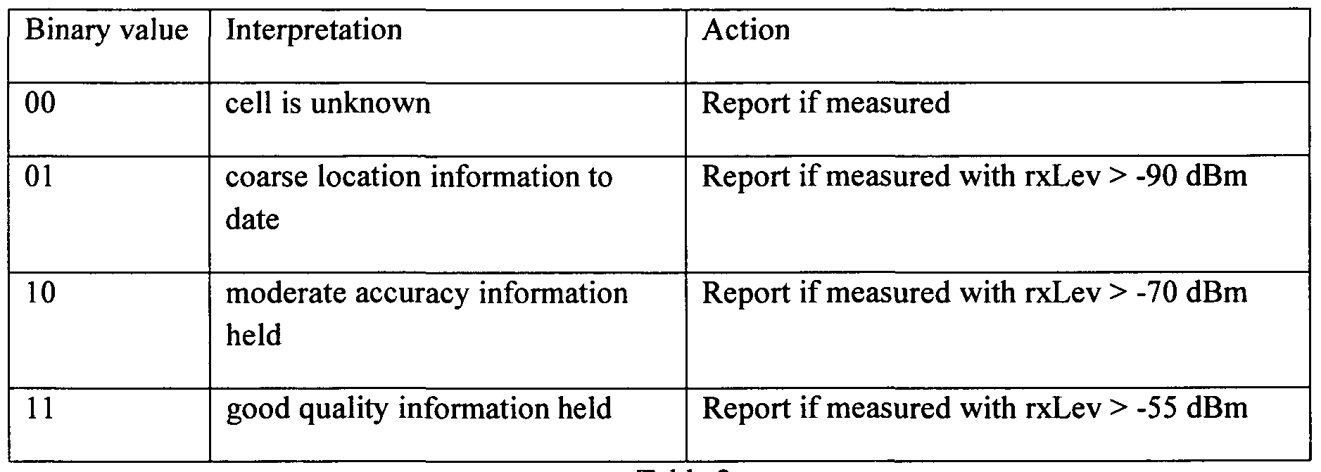
Table 2
Advantageously, certain embodiments of the present disclosure enable the client to focus the reporting of cellular measurements using Wi-Fi APs as a reference to only those cases where the Wi-Fi AP is known to the network database server (thereby yielding a reference measurement). With cellular base stations, the use of the tasking information described above enables the client to determine which cells have good quality information associated with them in the database. The relatively much larger number of Wi-Fi APs in existence compared to cells and correspondingly larger MAC address range however makes it difficult in practical terms to distribute the corresponding tasking information about known and unknown MAC address (2Λ48 combinations). A local version of the tasking information is available however in the Wi-Fi history list. Since the client maintains the list of Wi-Fi APs that it has reported to the network database server and the best quality reported, it can determine whether one or more of the current APs are known to the server (based on a previous report from this client) and whether it is likely to be known with sufficient quality to serve as a location reference for an unknown cellular BTS.
Figure 6 illustrates exemplary logic by which a client can determine whether to generate a report for a cell using a Wi-Fi measurement to provide a location reference.
The reverse reporting mechanism may also be applied in some cases, i.e. a measurement for one or more Wi-Fi APs is reported to the server using contemporaneous cellular measurements as the reference source. If the network database server holds a relatively accurate model for a cell and the terminal while camped on that cell can also hear a Wi-Fi AP, then the client can report the pair of measurements contributing to the network database server learning for that AP.
In this case the client can be programmed to generate a report only in the case that the terminal is sufficiently close to the cellular base station to constrain the location of the Wi-Fi AP sufficiently (i.e. the cellular rxLev exceeds a threshold). A suitable threshold rxLev for the cell could be, for example, -6OdBm, although any other suitable value could be used such as between -5OdBm and -8OdBm. The actual value could be defined in the tasking information sent to clients to enable it to be adjusted dynamically as the network model converges.
In many cases, if the terminal is connected to the Wi-Fi rather than cellular network, the cost of transmitting a measurement report is likely to be lower than the equivalent cost for cellular data so the threshold might be adjusted to enable greater reporting rates than over cellular, for example by lowering the threshold to -9OdBm. Figure 7 illustrates an exemplary processing flow by which the client can determine whether to generate a report for one or more Wi-Fi APs if contemporaneous cellular measurements are available.
From time to time the client application may collect measurements pertaining to one or more wireless networks, GPS, or any suitable combination thereof. The specific types of measurements will vary from device to device according to the capabilities of the device, the surrounding environment and also user configuration settings for the device. In certain embodiments, the client collects and stores any measurements in a time tagged format. When a report is to be encoded for transmission to the server the measurements at that time are analyzed and one or more is encoded depending on the relative priorities of the measurements as well as the capacity available in the reporting channel. For example if a single binary SMS is to be used, then the space available is 140 octets.
The information encoded in the report is presented using BNF notation where + indicates accumulation, {} indicates iteration of the item, () indicates that the item is optional, and | indicates a selection:
Report := MCC + MNC + 0{CellTableEntry} + 0{ShortIdTableEntry} + 0{WifiTableEntry} + 0{MeasurememTableEntry} + 0{GPSTableEntry} CellTableEntry := LAC + CID
ShortldTableEntry := ARFCN | UARFCN + BSIC | PSC WifiTableEntry := MACAddress + Age + (rxLevel) + (SSID) MeasurementTableEntry := Tablelndex + Age+ MeasurementType + (rxLevel) + (TimingAdvance) MeasurementType := CellTable | ShortIDTable
GPSTableEntry := Latitude + Longitude + Accuracy + Age
The age refers to the time between a measurement and the most recent measurement. The age may be defined as a number of seconds. Alternatively the age may be defined as a number of ticks where a tick refers to a known constant, or substantially constant, amount of time known to the relevant elements of the system that need to process the age information. As an example the interval could be known because all clients use a fixed sample interval.
The structure of the tables means that for a given report any of the tables may have measurements or may be left empty according to the information currently held in the measurement table. The encoding format means that GPS measurements may be included as opportunity affords. Advantageously, this minimizes battery depletion by not powering on the GPS solely for network acquisition but rather capitalizing on opportunities where the user or another application has activated the GPS.
In certain embodiments the client selects information to be reported according to the value that is likely to accrue from the measurement in the context. As an example, if the encoding is being done for a network acquisition report, then the objective could be to report as much information as possible that is not known to the server, along with information that conveys reference position information. Consider a case where a range of cells have been measured in recent cycles, some of which are known and some of which are unknown to the server (determined by the client by examining the tasking information). Assume further that a GPS fix has been recorded recently. The encoding would start with the most recent GPS fix and then in decreasing order of signal strength (if available), the unknown cells, followed by the known cells, space permitting. The reason for encoding unknown cells in reverse order of their signal level is because the stronger the signal level, the tighter the constraint on the location of that cell relative to a reference position (GPS in this case). In the case where the particular device does not support rxLev measurements, the unknown cells would be reported in increasing order of the time interval between their measurement and the GPS measurement time. Wi-Fi measurements typically would be encoded (space permitting) after at least one measurement per cellular base station has been encoded.
In certain embodiments a device may report measurements to support a location calculation, where the measurements correspond to one or more cells which are currently unknown. In such a case, the lack of any information in the database concerning those cells would mean that no location can be calculated. From a user's perspective this is a very negative experience and one that warrants significant effort on the part of the location service provider to avoid or mitigate. In some current systems when this happens there is simply nothing for the user to do other than move about while sending repeated requests hoping that the device may reselect to another cell that is known to the server.
Advantageously, in certain embodiments the application client can provide a mechanism to work around this. Consider first the case where the cell ID is unknown to the system, but the LAC is known, being associated with several known cells. The location server can return a failure indication to the application server, but can also return a location estimate which corresponds to the centroid of the cells which are currently associated with that LAC. The location uncertainty indicated to the user would also be relatively large, reflecting the footprint of the controller associated with that LAC value. The system can then present a coarse map covering the LAC area and offer the user two options. The first is to use the current displayed location and area to complete the original request. In some cases, this coarse accuracy may suffice; as an example consider a search for a business having a relatively uncommon name. A search in an area covering a few kilometers is likely to still resolve to the correct location. The second alternative for the user is to use the map to try to locate themselves by zooming in and using nearby features such as street names etc to determine their actual location. The user can then specify their location manually to the application via the cursor or any other suitable UI facility. The location specified by the user can then be translated from a screen position to a corresponding physical location by the application and used to update the location. The application can also provide an uncertainty value corresponding to that position measurement based on the current map zoom level. A suitable uncertainty value may be the extent of the displayed map divided by a factor between 2 and 10. The system can then use the location specified by the user in completing the original request, this can be initiated for instance by the application refreshing the request to the server, including the location specified by the user.
In the case that the user does provide a manual input of their current location, aside from satisfying the users service request, the system can also exploit the user specified position as a reference measurement for the currently unknown cell. This measurement can be sent to the gateway as with other network reports. In this case the measurement type in the GPS table indicates that the source of the measurement was human input rather than a GPS device. The benefit of marking manual measurements as such is that with human input there is a greater possibility of gross error, either accidental or mischievous. If subsequent client measurements corresponding to the cell are found to be inconsistent with the user supplied measurement, the exemplary process illustrated in Figure 9 when a cell has been detected to have moved, can be initiated more quickly to eliminate the error.
Depending on the latency between receipt of measurement reports and network update processing, it is possible that the same user could make further requests for location based services from the system before the previous manual measurement has been used to add the cell to the network database. In certain embodiments, a further enhancement in the user device is to retain the user specified location locally in memory as long as the device remains camped on any unknown cell(s) as determined from the tasking information. If further location requests are transmitted in this case, the client will include
in the GPS table a manual entry reflecting the location previously specified by the user. In this way in a series of requests the user will not be repeatedly confronted with an unknown location response and forced to re-specify the current location. Advantageously, having the client retain the earlier manual location indication from the user enables the subsequent service requests to be satisfied without requiring the user's location to be persisted in the application server, a problem from the point of view of managing server scaling and failover.
In some cases, in addition to the cell ID being unknown, one or more of the LAC, MNC & MCC may also be currently missing from the network database server(s). In such cases the same mechanism can be used to resolve the user location except that the initial map presented is at an even coarser zoom level. The system can use the worldwide definitions for MCC and present a map of the corresponding country, enabling the user to zoom in to their current location and preferably supply a manual location indication. Overall, although the user may have to carry out some intermediate steps this enhancement enables the location system and associated content or application server to successfully answer virtually all user requests which will minimize the rate of user disappointment.
In some cases it may be possible to use existing information to initialize the network model, without waiting for sufficient measurements to be reported by devices. The benefit of this is that it can unlock the circular dependency wherein users of the service are needed to provide measurements for the network learning process, but the service is poor or unusable until sufficient users are active and providing measurements. Having a way to initialize the network database can enable a useable service to be offered initially, making the task of signing up users easier. The following paragraphs describe several methods for initializing the cellular network database.
In certain embodiments, initially when there is no information available on a target cellular wireless network an empty database is created. The MCC & MNC for the corresponding network are initialized with the appropriate values for the network which can be determined from public listings of this information. Such information is available on many internet sites including the official sites maintained by the mobile telecoms industry associations (GSMA & CDG etc.). For models corresponding to fixed wireless networks such as the collection of Wi-Fi APs, the MCC & MCC are set to a system constant which effectively means N/A since in these cases the networks are operating in unlicensed spectrum and there is not necessarily any coordination between the different APs. After initializing a database in this way, subscribers will not be able to use the system for location estimation until further information is acquired describing the configuration of the radio network. Therefore the aim is to accelerate the acquisition process as much as possible. The tasking information corresponding to an empty cellular network model would be initialized and transmitted to
all available clients as early as possible. For GSM & UMTS networks, the initial tasking information would mark all cell ID values as unknown initially.
In some cases a MNO may be willing to make available a one-time extract of the radio network configuration information. This might be for instance in exchange for some consideration, but without having to commit to the overhead of maintaining the information and providing frequent updates.
In this case the database could be initialized using the information provided by the operator. In some cases one or more parameters of the models used by the network database server might not be available from the operator's extract and would therefore be initialized to default values. For example the covariance estimates corresponding to location uncertainty for each cell would be set to a value reflecting the estimated accuracy of the site information. A suitable value might for instance be [50Λ2, 0; 0, 50Λ2]. In some cases the information might be available in a format that is not directly compatible with the import format supported by the network database server. In this case, a custom script could be employed to reformat the data for loading by the corresponding network database server. In such cases, attributes such as environment type would also be estimated by the network database server and used to complete the network model initialization.
In some cases, to accelerate the initialization process a focused measurement campaign could be initiated using either general purpose or specialized measurement receivers together with GPS. For instance prior to service launch one or more vehicles could be equipped with GPS receivers and cellular terminals and driven around target areas to collect measurements. One suitable device could be a standard mobile phone which features cell, Wi-Fi and/or GPS capabilities. An application running on the phone can initialize the GPS and then collect cell, Wi-Fi and/or GPS measurements as the user moves around the target coverage area. In some cases, however, it may be desirable to collect measurements for all, or substantially all, cellular networks as well as Wi-Fi. One option may be to simply carry additional devices, one for each network and access technology. In other words for carriers operating both GSM and UMTS networks, two devices would typically be required. Yet another alternative is to use a dedicated device with the capability to monitor multiple networks simultaneously. Figure 38 illustrates such an exemplary device. It is equipped with multiple cellular modems each providing a host interface through which the controller can read the current access technology, current serving cell information including signal strength plus neighbor cell information and signal strength. In addition a Wi-Fi network adapter is provided through which the controller can obtain a list of the current Wi-Fi Access Points and associated signal levels. The device also features a GPS from which the controller can read location information. When activated the device periodically scans all the cell, Wi-Fi and/or GPS devices and records the reported information in a log file. The system provides a facility to upload such log files, whereupon the log file is parsed and individual
reference measurements are generated and added to the network learning collection using the GPS as a reference source.
In other cases an airborne approach might be preferred for collecting cellular network information. In this case a cellular band antenna could be affixed to the fuselage of a light aircraft and cellular terminals installed within the cockpit together with a GPS. One suitable flight plan would be a series of lanes spaced at one half or one third of the expected cell site separation in the area. In most populated areas local authorities impose a ceiling above which aircraft must fly. This ceiling is typically a few hundred meters. From the perspective of these measurements, the lower the better, otherwise the vertical directivity of outdoor cellular antennas will mean that the signal level at elevation will be greater for remote cells rather than those immediately below the aircraft. Typically such a flight would collect information only for macro cells. The path loss for indoor and microcells at a few hundred meters above ground level would typically be too great for these cells to be measured.
The measurement yield in such a campaign could be enhanced by using special purpose receivers which attempt to decode and report all cells in the area. In GSM for instance this would mean that the receiver attempts to identify all the BCCH channels and then repeatedly tries to decode the cell ID for each. This is in contrast to the normal operation of a GSM terminal in idle mode where cell ID reporting is typically confined to the currently selected serving cell.
The measurements collected during such a flight could be processed to estimate the locations of each cell by an algorithm that seeks the parameters for a BTS model which best fit the pattern of received measurements. One such algorithm employs a cost function which for each measurement computes a predicted signal level s at the location where the measurement was recorded using a particular set of BTS parameters (x, y, height, azimuth etc.) and compares this with the actual received level s. The cost C per measurement is given by: (s - s)z
C = σ2
where σ corresponds to the expected variation in the signal level to fading and multi-path. For an aerial survey, shadow fading is likely to be small compared to multi-path, therefore suitable values of sigma are likely to be between 3 and 6 dB. The algorithm repeats the cost calculation over a range of values of the variables and selects the set yielding the smallest total cost.
In some countries, radio spectrum management authorities maintain a database of registered transmitter locations. This information could be utilized (subject to the terms of use published by the
corresponding publisher) to accelerate the convergence and improve the accuracy of the locations more quickly. Such databases typically provide details such as location, frequency band, antenna type & orientation & max transmit power. An example of such a database can be found at http://web.acma.gov.au/pls/radcom.
In certain embodiments the database can be filtered to extract the information pertaining to the specific network of interest (both by operator and by frequency band) to obtain a list of candidate locations. As measurements pertaining to specific cells are accumulated by the network database server, the degree of consistency between the measurements and nearby candidate locations can be assessed. When the consistency is sufficient and the statistical significance reaches a suitable threshold, a match can be declared and the more accurate location assigned.
One method for performing a calculation to determine whether a candidate location from such a database is a suitable match for a set of measurements accumulated by the server is using the cost function described below. To check the consistency, certain embodiments first initialize a BTS model with the location and antenna orientation from the database and then calculate the sum of the residuals between the measurements and predictions using the BTS model. If the sum of the residuals is smaller than the threshold then the location is accepted as a good fit and the x and y parameters for that BTS model are "snapped" to the location obtained from the database.
In some cases, the public database may not include information on the antenna orientation. The process above can still be applied by first using a solver to find the model angle for which the residual is smallest and then proceeding with the consistency check.
The accumulated information reported by one or more devices is combined by the system into a model which can then be used by a location server to estimate the position of users.
While certain embodiments can be used to accumulate information concerning a single network to support location of wireless terminals using that network, it may also be used to accumulate information pertaining to a large number of networks. It is preferable therefore to partition the work in some way. One benefit of this is that it enables the processing to be distributed among multiple processor elements. Additionally, when the information is used for location, if the totality of the information is partitioned appropriately then when the location server wishes to use the information pertaining to a few cells to estimate the location of a specific device, the complexity of the queries to find the required information as well as the volume of information to be transferred can be minimized.
One way to partition the problem is by separating the models for different networks. In the case of cellular networks, this can be done based on the MCC & MNC which is reported by the client software along with any measurements. Within each network it may also in some cases be advantageous to separate the network into sub-networks containing 2G & 3G cells respectively.
For fixed or mobile wireless networks operating in unlicensed spectrum (for instance Wi-Fi) there is no equivalent grouping of Access Points and therefore the system treats all such elements individually. If it is necessary to partition the ad-hoc collection of Wi-Fi APs for instance to provide to a Location Server serving subscribers in a particular country, then the partitioning can be done based on location. In other words, a sub network containing all APs within some physical region can be extracted. In some cases, a location server may be configured to serve subscribers of a specific cellular network only. In such cases, a suitable sub-network model for the unlicensed network can be extracted by selecting all elements that fall within the physical footprint of the cellular network.
A related aspect of the partitioning of the models is that the storage for the reports can be segmented by network. This may simply mean that the measurements are stored in the same database in tables maintained by different processes or alternatively in cases where a very large number of users are being supported across a very large number of networks, separate databases may be used. The benefit of the separation between networks is that it affords considerable flexibility & scalability in operating the system and managing computing & storage resources for it. A further potential advantage that arises from separating the processing for different networks is that in some regions the network database and location servers may be able to be supplied with terrain or clutter information which can be incorporated in the propagation modeling process as is well known in the field. By separating the processes it may be more convenient to provide the information when available without interrupting the processing for those networks where no such information is available or creating a dependency in all network database processes on having such information.
Figure 2 illustrates an exemplary lifecycle for a network model according to certain embodiments. At an appropriate time the model for the network is initialized in step 100. This could be done when the system is initially configured and empty models are created for all networks that are to be modeled. Alternatively this initialization could be triggered when the first measurement pertaining to that particular network is received by the network database server. After initialization, the model goes through repeated cycles of measurement collection in step 110, model update in step 120, and tasking information update in step 130. While the process is shown as sequential, in practice there may be some temporal overlap between the collection and update processes. This is because once an update has been initiated, other measurements may continue to arrive for processing. Such measurements will be collected and stored for the next update processing cycle. The trigger for commencing an update
can vary depending on the needs of the applications. In certain embodiments, the update may be triggered periodically, for example every hour, every two hours, or once a day. Depending on the configuration of the system and processing resources it may also e preferable to stagger the updates across different network models so that the updating proceeds with one network model at a time. An alternative basis for triggering the update processing may be based on the number of measurements that have been collected. This could for instance be triggered once a suitable number of new measurements have been received, for example, at least 50, 100, 200, 500, 1,000, 10,000, or 15,000. Yet other criteria could be when new measurements have been received which pertain to a proportion of the cells in the network. For instance if new measurements are available for, for example, 2%, 5%, 10%, 15%, 20% or other suitable number of the cells in the network then the update processing could be initiated. Yet another option for triggering the processing could be to allow it to happen as fast as the data & processing resources permit. In other words once a particular update cycle completes, the next one starts, using as input all the measurements that were accumulated while the previous cycle was being completed. The merit of this approach is that the accuracy & coverage enhancements enabled by recent measurements will be available for users as soon as the available processing resources permit.
As illustrated in Figure 2, once the update processing has been completed, the tasking information may be updated to reflect the state of information in the network model for use by clients to guide their network reporting as well as measurement reporting for location calculation. In certain embodiments, the tasking information has an associated revision number that corresponds to the database revision from which it originated. The network database server may also retain previous versions of the tasking information. Given that the database revision is likely to be updated relatively frequently, in some cases it will be preferable not to distribute every update to every client. Therefore it may be preferable for each client to record the version of the tasking information which it currently holds. At suitable times the client may query the network database server to determine the number of changes between the revision it holds and the latest revision of the tasking information. The client can then initiate a download of the updated information as required.
The quality of the model will improve with greater availability of measurements. Figure 9 illustrates an exemplary lifecycle for each element of a network model, corresponding to a BTS or other wireless access point or transmitter.
The following description will be presented using the example of a cellular network BTS however the same lifecycle is equally applicable to other types of wireless access points or transmitters. When a network model is first created for the corresponding network, there will be no cells in the model. If information is provided to initialize the network model, the cell may be initialized with that
information. Examples of such sources of information are included in a later section. Typically the information provided will include the location of the cell, its identifiers (e.g., cell ID & LAC), the frequency band and the type of antenna. In some cases information may also be provided on the antenna orientation & height.
In the absence of external initialization information, the cell model may be initialized on receipt of the first measurement pertaining to that cell. In this case the identification parameters can be initialized before the measurements are used in the normal update processing to set the other parameters such as x and y.
In certain exemplary embodiments the model for each cell includes some or all of the parameters shown in Table 3 below. Some of the parameters may be left uninitialized or may be assigned default values in some cases depending on the type of transmitter being modeled.


Table 3
The update processing step 240 is carried out using all the available measurements at the time of processing. One aspect of the update processing may be to check whether the collection of measurements reflect a change in the cell. For instance if a cell is relocated, then the older measurements will reflect the original location while the more recent ones will reflect the current location. A test can be carried out to check this, by calculating the residuals between predicted values using the current model and the measured values. By maintaining a history of the residual values corresponding to each version of the network database, a change will be reflected in growing residuals. Use of a suitable threshold on the residuals, for instance based on the chi-square distribution will enable this type of scenario to be detected. In the event that the test does not indicate any change then the parameters of the model are refreshed based on the available measurements. If there is a change, then further processing can be done to identify the time at which the change is likely to have happened and the historical measurements are trimmed, retaining only the measurements which are consistent with the current configuration.
Another aspect of the update processing for each cell may be to determine the type of cell (Macro/Micro/Pico). Yet another aspect may be to determine whether the cell antenna is omnidirectional or directional in order to use a suitable gain pattern in the propagation modeling. Yet another parameter to be estimated is the location of the cell. If observations of the cell are found to exhibit an omni-directional pattern, the location of the cell is simply the mean of the observations. The antenna angle is set to zero since any value will do. If on the other hand the cell is determined to
exhibit a directional radiation pattern, it may be advantageous to estimate both the antenna location as well as its orientation.
In the initial phases, the data may not provide sufficient information to determine robustly either the type of the antenna or indeed the orientation. Therefore a simple, more robust model may be used which is to estimate the location as the mean of the reference locations available for a cell. The footprint or coverage area of the cell can be estimated directly from the spread of these reference locations and expressed as a 2_D Gaussian with mean X and covariance C. Figure 12 exemplary illustrates this using a simulated network. A collection of observations are simulated, each consisting of a single cell ID measurement (no rxLev) for the highlighted sector and an accompanying GPS position fix. The location for each measurement is marked with a dot. The calculated mean is marked with a cross. The ellipse in the plot shows the area represented by the covariance matrix.
Figure 13 exemplary illustrates the same network, but this time showing the measurements that would be reported with handsets capable of reporting rxLev as well as serving cell ID. The rxLev for each measurement is reflected in the size of the dot. For the purpose of the simulation, a propagation model was used and 6dB log normal fading was added to the idealized rxLev at each point. In this case the measurements can be characterized by mean and covariance of the 3 element observation vector [x,y,rxLev]. Where the system has accumulated a mix of cell ID only and cell ID+rxLev measurements, the position mean is estimated across all measurements while the mean rxLev is calculated only across the rxLev measurements. Similarly the Cl 1, C12, C21 & C22 are estimated across the whole set of measurements while Ci3 & C3i are estimated using only the rxLev measurements.
In order to maintain a consistent representation of all cells regardless of their stage of modeling, the mean and covariance characterizing the footprint can be converted into an omni-directional BTS model, with the transmit power level being adjusted to achieve a footprint of equal area to the 90th percentile ellipse. The x & y coordinates of the BTS are set to the mean of the ellipse.
This omni-directional model will remain in effect until sufficient data are available to determine whether the transmission pattern is directive or not. Note that even if a few very accurate GPS referenced measurements are available for the cell (i.e. associated with very strong rxLvs which constrain the cell location very tightly), the omni-directional model will remain in effect until sufficient data are available to determine the directivity (or not).
If sufficient data become available for the directivity test, a check is done. If the data indicate that the reception patterns is sufficiently directive then the BTS model is updated & the antenna type is set to
a suitable pattern type. The antenna orientation is then estimated from the data and used to initialize the corresponding field in the BTS model. In this case, the BTS location also has to be determined using a different approach because the most likely location for the cell no longer lies at the centre of the measurements.
In preferred embodiments, estimating the BTS location and antenna orientation involves the minimization of a penalty function. Such minimization techniques are well known in the field of data analysis and statistical estimation. The model parameters (unknowns) to be estimated are the antenna location x,y & antenna orientation, theta. In this case, the penalty function is evaluated over the available measurements, and for each measurement a predicted signal level is calculated at the associated location, using a suitable antenna pattern such as that exemplary illustrated in Figure 14, which is a smoothed representation of a measured pattern for an antenna characterized by 16 dBi peak gain and 60 degrees beam width. This type of propagation modeling is well known to those in the field, being described in texts on the subject such as S. R. Saunders & A. Aragon-Zavala, Antennas And Propagation for Wireless Communication Systems: 2nd Ed, Wiley, 2007. For any given tuple of x,y and theta, a cost or penalty C is calculated for each measurement as:
C = Cs -*)2 σ2-
The model above requires the measurements to include rxLev. In some cases rxLevs may not be available (serving cell ID only measurements). In this case the penalty function C is of the form:
L " 2σz
Where s' is the maximum expected rxLev for which a typical value is -4OdBm.
A common technique is to assume that the sum of the costs calculated in this way across the measurements is a chi-squared random variable. In this case, one can look up the cumulative distribution for the corresponding number of degrees of freedom and choose a consistency threshold. In the present case a suitable threshold may correspond to the 90th percentile or some other percentile between 70 and 99.5. If the sum of the calculated residuals falls below the chi-square value corresponding to this threshold for the number of degrees of freedom, then the model may be considered an acceptable fit to the data, otherwise the model may not be accepted as sufficiently consistent.
The BTS model used in the system can include a radio frequency channel parameter such as a (Universal) Absolute Radio Frequency Channel Number ((U)ARFCN). This reflects the channel used
for the broadcast or beacon channel in the downlink. In preferred embodiments, for each cell being modeled in the system, this frequency parameter can be determined from the reported measurements. This enables a suitable propagation model to be employed in connection with this cell applied (there are significant differences in the attenuation of signal power as a function of range between the 450, 900, 1800, 1900 & 2100 MHZ bands typically used by cellular networks). The ARFCN field of the BTS model is initially set to a system constant signifying UNKNOWN.
Some wireless mobile devices provide radio frequency information. As an example the GetCellTowerlnfo function supported by the Windows Mobile Radio Interface Layer reports the BCCH of the serving cell. In a deployment with a mixture of devices where some report frequency information and some do not, certain embodiments can exploit the measurements from those devices which do to update the model with the correct frequency. As soon as a measurement is received from a device which reports this information (encoded in the short Id table), the corresponding field in the model is updated. The benefit of maintaining this information in the network model is that a more appropriate propagation model can be used, i.e. the model for path loss versus range can be selected from the set of characteristics which are typically used in the industry.
When modeling the propagation of a cell, the propagation modeling engine in the present system uses a suitable model for the frequency. With a cell for which the ARFCN is unknown, a mid-range propagation model can be used and the greater uncertainty is reflected in a larger fading sigma value.
In many cases, cell sites are deployed in a sectored configuration using directive antennas to enable greater frequency or code reuse and thereby increase capacity.
For a system attempting to identify and localize all the cells in the network this typical clustering can be leveraged to accelerate the acquisition process and/or enhance the accuracy of the results.
The most common configuration consists of 3 sectors spaced approximately 120 degrees apart.
Another common pattern in cellular network configuration is to orient the three sectors at angles (with respect to North) of approximately 0 degrees, 120 degrees & 240 degrees.
In some cases an operator may relocate a cell. Compared to the other types of changes which are carried out in the evolution of a wireless network (commissioning new sites, returning etc.) this is a relatively rare occurrence. Nevertheless, if a cell is moved and the network database server fails to detect this and update the database, subscribers making location requests near these cells will start to
receive spurious answers. This in turn could damage the reputation of the service provider and decrease the commercial potential of the service in supporting some value added services.
Therefore as measurements corresponding to a particular cell are received and processed, in addition to updating the current estimate, the system will also maintain integrity information for the cell. This can be collected in the form of residuals which are accumulated. In the case of a relocated cell, the residuals will tend to grow over time. By application of a suitable threshold, the system can detect that a change has occurred and simply restart the acquisition process for that cell, using the most recent measurements to initialize the process (rather than eliminating everything and having a period where there is no coverage for that cell).
In some networks, multiple transmission points may be deployed for a single cell. Typically one transmission point is referred to as the donor and the one or more others as repeaters. In some cases the repeaters may provide very limited coverage areas, for instance indoor coverage in the shadow of the donor macro cell. In other cases, the repeaters may themselves serve a large physical area.
If measurements are received first for one transmission point and then another, it may appear that the cell has moved (as disclosed above). However if the reality is that there are multiple transmission points then it would be advantageous for the system to be able to resolve this and update the model to reflect the distributed footprint associated with that cell identifier.
Certain embodiments of the present disclosure resolve this by employing a sufficiently large accumulator threshold on the residuals before declaring a moved cell and restarting the acquisition process for that cell. The integrity monitoring will also include the capability to detect multimodal concentrations of reports that would distinguish a donor/repeater scenario from a moved cell scenario.
In some cases, rather than a donor/repeater arrangement, the network may be configured with multiple transmission points of equal coverage in an arrangement sometimes referred to as a split cell. The database server update processing can detect this because the requirement to accumulate statistically significant sequence of measurements before declaring a moved cell will be unlikely to be met as measurements corresponding to each transmission point will be received over the update period.
Another common change in cellular wireless networks which certain embodiments of the present disclosure may be able to accommodate is a change of one or more of the parameters used to identify the cell. For example, this could be a change of cell ID in GSM or a change of LAC. The latter is more common as one or more cells are re-parented (i.e. associated with a different BSC). Certain embodiments can identify this as a change of ID (cell ID or LAC) based on the fact that one cell in the
network will stop receiving any measurements and a new one will start. The server will periodically scan for cells that have not been updated for some time and for each such cell, initiate a search for a recently activated cell entry having radio measurements which are consistent with those for the old cell. The time sequence for the matching entries will typically show a clean break around the time that the change was applied in the network. The process for confirming the alignment of the two sets of measurements can be done using any one of the well known tests to confirm that two sets of samples come from the same population.
With Wi-Fi networks a similar scenario could occur if the user replaces one Access Point with another either when upgrading hardware or perhaps following a hardware fault. In this case the new AP will typically serve the same area however the MAC address detected by a Wi-Fi capable device nearby would be different.
The diversity of measurements that can be received for processing and the use of contemporaneous measurements of different wireless nodes to estimate the locations of each makes the task of designing a processing framework difficult. To illustrate, assume that at some instant TO, the network database contains a model for 2 cells as shown in Table 4 below. This version of the database is N. Note that the X, Y values stored in the network model are in a suitable local grid rather than latitude/longitude because grid coordinates are more suitable for the processing to be done.

Table 4
At time Tl, a report is received from a user device containing the following information: Header
MCC: MNC: 505 1
Cell Table
Num Cells
2
LAC cell ID
1 1 1000
11 2000
Short ID table Num short Ids
0 ARFCN BSIC
Wi-Fi Table
Num APs
0
MAC SSID
Measurement Table
Num measurements
2

1 0 CELL 1000 NOT REPORTED
2 30 CELL 2000 NOT REPORTED
GPS table
Num fixes Base Lat Base Long Alt
0 0 0 0
Time Lat offset Long Offset Accuracy Type
In this case successive measurements are reported for cells 1000 & 2000 but there is no GPS or other source of independent position information. Assuming that the current information (in dbase version N) for cells 1000 & 2000 reflects a diversity of sources, it would be preferable to use the information in this measurement report to update the models for these cells in database version N+l. There is to some extent a circular dependency.
Certain embodiments of the present disclosure can overcome this circular dependency by extracting a separate measurement report for cell 1000 with reference to cell 2000, using the location parameters for cell 2000 from the previous database (version N). Likewise cell 2000 is updated in dbase version N+l by creating a separate reference measurement for that cell with reference to cell 1000, using cell ID 1000's parameters from database version N.
In principle there is a risk of creating an unstable feedback loop between the models for each cell in the pair. However in practice the models for each cell will also reflect contributions from other cells, from GPS and Wi-Fi and therefore should not result in a self fulfilling prophecy.
The process described above may be completed by the preprocessor for all measurements in the database. Specifically for each cell or wireless AP reported in a measurement a new location report is created in a temporary processing area. The update processing per cell then consists simply of collecting all the individual measurements corresponding to that cell and combining them as described previously.
Figure 10 illustrates an exemplary preprocessor. The table on the left of the figure represents the measurements transmitted by devices since the last database update and collected for use in the next update. The preprocessor scans each measurement in turn and extracts the information in it, creating smaller, individual reports for each of the cells or transmitters featured in the report. The table on the right represents these individual cell measurements extracted and formatted by the preprocessor for use in the next database update cycle.
Figure 11 shows an exemplary flowchart of the steps carried out by the preprocessor for each measurement report. It iterates over all the cells featured in the report and for each carries out the following steps:
(1) Choose the next reported cell in step 1100.
(2) Obtain a location estimate (and associated covariance) for the device at the time the measurement of that cell was recorded in step 1 110. This location estimate is preferably calculated in a way that is designed to avoid feedback. If the original report included a GPS fix then the location used for the device is the GPS fix. If no GPS fix was available then the location estimate is calculated by the location server using all measurements, except those pertaining to the cell that is being analyzed in this cycle to avoid a self reinforcing feedback mechanism. From the estimated device location, a location estimate and an associated covariance matrix for the cell under analysis are obtained.
(3) Save a measurement to the database for this cell, containing the cell details, the estimated location of the cell and the associated covariance in step 1120.
(4) Determine if any more cells are reported in the current measurement report in step 1 130.
For the measurement report presented above, two cell measurement records would be created as illustrated in Table 5 below.

Table 5
For the sake of this simple example we have assumed that the cell models for both 1000 & 2000 in version N of the dbase are omni-directional and therefore the location estimate for the device and in turn the measured cell correspond to the current origin of the referring cell. The covariance estimate for each cell is calculated as the combination of the uncertainty in the referring cell location as well as a term reflecting the uncertainty relating to the location of the cell with reference to the current device location.
Although the example shown above relates to a pair of cellular measurements, the same process could be applied for a pair of Wi-Fi APs or a mix of cellular & Wi-Fi nodes or any other suitable combination of measurements.
The network learning framework defines the way in which reference measurements for transmitters are derived from observations of radio transmitter signals, the way in which the reference measurements are modelled and the way in which the transmitter characteristics themselves are modelled, and the way in which the reference measurements are used to obtain estimates for the said transmitter characteristics. The transmitter characteristics can subsequently be used as to support other applications such estimating the location of a receiver.
By an observation we mean a set of wholly or substantially contemporaneous readings from one or more wireless sensors in a device. Such sensors include cellular radio devices and Wi-Fi access point network adapter. For some sensors the readings in an observation may correspond to multiple transmitters. For example, where multiple access points are in the vicinity of a Wi-Fi access point network adapter typically returns readings from each such access point. By contrast a cellular receiver typically only reports readings from the one transmitter commonly referred to as the serving cell.
An observation may also include a substantially contemporaneous location estimate. Such a location estimate may derive from a GPS receiver associated with the device. Where an observation includes a location estimate it may also include an indication of the uncertainty of the location estimate. Where an observation includes a location estimate it may also include the source of the location information, for example GPS.
Each reading within the observation will typically include at a minimum the type of transmitter and an identifier for the transmitter that was detected. A reading may also include other attributes of the detected signal. An example of such an attribute is a signal strength indicator such as the detected signal strength in dBm. Another example of such an attribute is the SSID of a Wi-Fi Access Point.
A device may accumulate a sequence of one or more observations. This sequence may be augmented with one or more additional attributes. These additional attributes may be applied by the device or by a server subsequent to the sequence having been sent to the server by the device. One such additional attribute is the type of device that made the observation. Another such additional attribute the ID of the device that made the observation. Yet another such additional attribute is a timestamp. Such a sequence may also have associated with it a location estimate and an associated uncertainty and optionally the source of the location estimate. Each observation within the sequence may have associated with it an indication of the elapsed time since the immediately preceding observation. Such an indication may be a measure of elapsed time. Such an indication may be implicit where the observations are made at a known and constant rate.
In certain preferred embodiments the observations that comprise a sequence are recorded at a fixed interval, or substantially fixed interval. When the sequence of measurements is received by the server the timestamp is applied. The server, knowing the observation sampling rate, is then able to extrapolate the approximate time at which each observation was made. The server may augment the sequence with a location estimate. Such an estimate may be derived by the server facilitating an interaction between the device user and a map to obtain a location estimate. This may be of particular benefit when the sequence of observations does not contain location estimates.
The type of transmitter indicates the nature of the signal that has been observed. Examples of these include Wi-Fi access point, GSM cell, UMTS cell, CDMA cell, WCDMA cell, LTE base station and WiMax base station.
The identifier is a set of one or more attributes of a transmitter that enables that transmitter to be differentiated from other transmitters. One attribute that may be used as part of the set is the type of transmitter, for example GSM cellular, UMTS cellular, and Wi-Fi access point. Another attribute that can be used as part of the set is an identifier that is transmitted by the transmitter and that is unique across a given type of transmitter. Examples of such attributes include: for GSM cellular the CGI (Cell Global Identifier consisting of the MCC, MNC, LAC and CID) associated with each BTS (Base transmitter station), and for Wi-Fi the MAC address.
The location of the measurement is represented as a set of coordinates. Typically the coordinates will either be in geodetic format (latitude and longitude) or in grid format (easting, northing and grid zone).
The location uncertainty (also referred to as accuracy) is a measure of quality of the location estimate that is associated with a measurement. When combining measurements to provide an overall model
for a given transmitter this uncertainty provides the basis for determining the amount of emphasis applied to each observation. Typically, the more accurate the location estimate the greater emphasis applied to that observation in the data fusion process.
The source of the location measurement indicates the reference from which the location information is obtained. Examples of such sources include direct measurement such as is provided by a GPS device, or inference derived from an existing model for the coverage footprint of a Wi-Fi, WiMax or cellular transmitter, direct user input of the location, as well as location information from third party sources such as a database. User input is process that involves direct human intervention. This may include interacting with a map display on a mobile device to indicate the current position and direct input of coordinates by the user into the mobile device or the server. Third party data sources may include a database containing information about the location and or footprint of one or more wireless transmitters.
The timestamp represents the date and time at which the measurement was made. Typically an accuracy and resolution of 1 to 10 seconds for the time is sufficient. Although other ranges of time may be used in appropriate situations.
The received strength of the observed signal from a particular transmitter may sometimes be available. In some cases the signal level may provide an indication of how close the measuring device is to the transmission source, as the stronger the signal the closer the device is to the transmitter. In particular the signal strength may provide an indication of whether this observation was made closer to the transmitter than other observations.
Mobile devices may provide a means for obtaining details about the type of device and or the specific device itself. An example of the device type is the TAC (Type Approval Code) which identifies the type of device in GSM and UMTS. An example of a specific device identifier is the IMEI (International Mobile Equipment Number) which is a unique identifier assigned to each GSM and UMTS mobile terminal.
In certain embodiments the network learning process may use observations derived from data captured for other systems. Provided that the data includes information that enables the temporal relationship between measurements to be established it should be possible pre-processed into a format such that it can be presented to the system as an observation containing measurements of one or more wireless transmitters. An example of such a source of data is zone-based location system in which messaged from the mobile device to the server contain measurements pertaining to one or more cells.
A sequence of observations may be deconstructed into a set of reference measurements. One or more of the observations in the sequence may be deconstructed. For each such observation one or more reference measurements may be created for each transmitter within the observation. Each reference transmitter measurement represents an instance of a particular transmitter having been observed relative to some other reference. A reference measurement includes an identifier for the transmitter, a timestamp, location coordinates for the reference measurement and the uncertainty associated with the location, and the source of the location coordinates. The reference measurement may also have associated with the measured signal strength if the observation contained a signal strength measurement for that transmitter.
The identifier in the reference measurement is the identifier of the transmitter obtained from the observation.
The timestamp for the reference measurement is that of the observation from which the reference measurement derives.
The location coordinates and associated uncertainty may derive from a number of sources. One such source is location data that is part of the observation, for example a wholly or substantially contemporaneous GPS observation. Another such source is location data that is part of an another observation within the sequence. When using such an observation the uncertainty assigned to the location estimate for the reference measurement may be adjusted to account for movement between the time the location estimate was made and that of the reference measurement in question.
Another source for the location estimate for the reference measurement is proximity to other transmitters inferred by the detection of other transmitters. Such a transmitter may be in the same observation. Such a transmitter may be in another observation from the sequence. Of particular importance are the observations adjacent in the sequence to the observation in question as the physical distance between the points at which the observations were made is likely to be smaller. In the certain embodiments the location estimate used in such cases is the centroid of the transmitter footprint model and the uncertainty is the extent of the transmitter footprint as measured by the covariance of the footprint model.
In certain embodiments the reference measurement accuracy is expressed as a scalar quantity. When using the transmitter footprint model as a location estimate, the footprint extent may need to be converted to a scalar quantity. For example if the footprint extent is modelled as the covariance of a 2D Gaussian PDF then the scalar accuracy may be obtained by taking the 4th root of the determinant of the covariance matrix.
The reference measurements derived from an observation are obtained by separating out each of the identified transmitters and creating one or more reference measurements for each transmitter. In certain embodiments a set of reference measurement for a transmitter is generated by pairing that transmitter with each of the other transmitters from the same observation. In certain embodiments a set of reference measurement for a transmitter is generated by paring that transmitter with each of the transmitters from the adjacent observations from the sequence. In certain embodiments and where the observation includes a location measurement, such as is provided by a GPS receiver, a reference measurement may be created pairing each identified transmitter with the location estimate and associated uncertainty.
In the certain embodiments the set of reference measurements for an observation is generated by pairing each transmitter in the observation with the location estimate, if present, with each of the other transmitters in the observation, and with each of the transmitters in the adjacent observations. Reference measurements are not generated for duplicated transmitter pairings or self-referential pairings. This is illustrated via the following example.
An observation M references cell A and Wi-Fi APs W and X. The next observation N references cell A and Wi-Fi APs W and Y and includes a GPS location estimate. The next observation includes cell B and Wi-Fi APs X and Y. The reference measurements generated by processing observation N are as follows: A with GPS, W with GPs, Y with GPS, A with footprint for W, A with footprint for Y, W with footprint for A, W with footprint for Y, Y with footprint for A, Y with footprint for W, A with footprint for X, W with footprint for X, Y with footprint for X, A with footprint for B, W with footprint for B and Y with footprint for B.
In certain embodiments a reference measurement is made by pairing some or all combinations of two transmitters present in the observations. If for a given pairing of transmitters A and B where a reference measurement for transmitter A is referencing the location of transmitter B and where the existing network model contains a footprint model for transmitter B, the location estimate is assigned to the reference measurement for A uses the transmitter footprint model of transmitter B. Where the network model does not include a given transmitter the reference measurement is created with a deferred location estimate referencing the unknown transmitter.
In certain embodiments a reference measurement corresponding to a transmitter in an observation may be obtained by calculating an estimate and associated uncertainty of the location of the device when the observation was made, and using as the location information and accuracy in the reference measurement, the estimated location and uncertainty for the device.
In certain embodiments the sequence of observation or part thereof is examined to establish whether the device has moved during the period of time that applies to the observations so examined. If the device was not to have moved a significant distance then location estimates from one observation may be applied to one or more other observations. As an example if one or more Wi-Fi access points are present in two or more observations within a sequence then the device may be deemed stationary over the period between these observations. If the device was deemed to be stationary then the location estimate associated with the sequence, if present, may be applied to one or more of the observations. If the device was deemed to be stationary then reference measurements may be generated by referencing transmitters from non-adjacent observations as the location for the reference measurement.
In certain embodiments reference measurements for a Wi-Fi access point are typically created using another Wi-Fi access point model as the location estimate is that reference transmitter was measured substantially or wholly contemporaneously with that access point. For example an observation O contains measurements of Wi-Fi access points W and X and another observation P contains measurements of Wi-Fi access point Y. For access point W a reference measurement may be created using the transmitter model for access point X as the location as it is part of the same observation. Creating a reference measurement for access point W using the transmitter model for access point Y as the location is conditional upon the elapsed time between the observations O and P. If the elapsed time between O and P is greater than 1, 2, 5, 10, 15, 20, or 30 seconds then there exists the possibility that W and Y are not actually close enough to warrant the generation of the reference measurement.
Locations are modelled using a probability framework. This enables algorithms to be used to derive a model for a transmitter using its reference measurements. A GPS location estimate and an associated accuracy indicator such as RMS error or Circular Error Probably (CEP) can be converted into a PDF. Similarly a coordinate obtained from a user in the form of a map reference can be modelled as PDF. In this case the PDF will model the accuracy of the underlying map data and the accuracy with which the user, on average, can specify their location from that map. An indicative accuracy would be 1/5, 1/8, 1/10, or 1/20 of the map zoom level. In certain embodiments the PDFs used will have a two- dimensional Gaussian distribution.
In some observations one or more of the measured transmitters may not be known to the system. Furthermore, there may be no other source of location information corresponding to the observation. For some of these observations there may not be any known transmitters in earlier or later measurements. In such scenarios the location information within the reference measurement may be marked as a deferred location. In a deferred location information is stored enabling the system to
populate the location coordinates and uncertainty at a later time when suitable information has become available.
In the reference measurement the deferred location estimate may be represented by a record of the proximity to an unknown transmitter identified using its identifier. The deferred location estimate may reference proximity to an unknown transmitter from the same observation or the preceding observation or the succeeding observation.
For example an observation contains transmitters A, B, and C. The previous observation contains transmitters X and Y and the next observation contains transmitter D. All of the transmitters are unknown to the system at the time. For the observation containing A, B, and C a set of reference measurements is made. For transmitter five reference measurements are created each having a deferred location estimate indicating proximity to transmitters B, C, X, Y, and D respectively. Similarly five reference measurements are created for each of transmitters B and C.
The following examples illustrate the generation of reference measurements for specific combinations of transmitter measurements within the same observation and across adjacent observations. In the figures associated with these examples the true location of the transmitter is shown by a + symbol. For directional cellular transmitters the directionality of the transmitter antenna is shown via a circular arc. The radius of this arc is somewhat arbitrary. The centroid of the footprint model is indicated by a * symbol. The extent of the footprint is shown as a contour of constant probability which, when the reference measurement uncertainty is expressed as a scalar, will be a circle. In the following example the location uncertainty is expressed as a scalar. This scalar quantity is derived as the 4th root of the determinant of the footprint model covariance matrix.
Typically cellular receivers only report the current serving cell. To create a reference measurement for a cell with respect to a different cell the reference cell will need to derive from a different observation. An observation containing measurements of 1 cell may be used to create a reference measurement for that cell by using measurements of another cell from another observation in a sequence. In certain embodiments the another observation will be an adjacent observation.
In certain embodiments an observation measuring cell B may result in a reference measurement being created using cell A as the reference where cell A was observed in an adjacent observation from the sequence. Provided a model for cell B already exists in the network model a reference measurement for cell A may be created using the footprint model for cell B to provide the location and uncertainty for the reference measurement.
Figure 15 illustrates the generation of a reference measurement for cell 21701 based on an observation containing cell 21701 and an adjacent observation containing cell 20503. The figure shows the reference measurement for 21701 is created using the footprint model for cell 20503. In this example the reference measurement for cell 21701 may be made irrespective of whether there is an existing footprint model for cell 21701 in the current network model.
In certain embodiments an observation measuring access points B and A may result in reference measurements to be made for A with respect to B or B with respect to A or both. Provided a model for access point B already exists in the network model a reference measurement for access point A may be created using the footprint model for access point B to provide the location and uncertainty for the reference measurement. Similarly a reference measurement for access point B may be created using the footprint model for access point A provided a model for access point A exists. Where a footprint model does not exist a reference measurement may still be created by using a deferred location estimate.
In certain embodiments where an observation measuring access point A is succeeded by an observation measuring access point B a reference measurement for A can be create using B as the location reference. Provided a model for access point B already exists in the network a reference measurement for access point A may be created using the footprint model for access point B to provide the location and uncertainty for the reference measurement. If no such model exists for B then the location estimate can be set as a deferred location estimate with respect to B.
Figure 16 illustrates the generation of a reference measurement based on the observation containing 2 Wi-Fi Access Points having MAC addresses 87723982376 and 62644269161, The figure shows the reference measurement for 87723982376 is created using the footprint model for access point
62644269161. In this example the reference measurement for access point 87723982376 can be made irrespective of whether there is an existing footprint model for access point 87723982376 in the current network model. A reference measurement may also be made for access point 62644269161. If there is a footprint model for cell 87723982376 then the reference measurement location and uncertainty will use this footprint model. Otherwise the reference measurement would need to include a deferred location reference to access point 87723982376.
In certain embodiments an observation measuring access point A and cell B may result in reference measurements to be made for A with respect to B or B with respect to A or both. Provided a model for access point B already exists in the network model a reference measurement for access point A may be created using the footprint model for access point B to provide the location and uncertainty for the reference measurement. Similarly a reference measurement for cell B may be created using the
footprint model for access point A provided a model for access point A exists. Where a footprint model does not exist a reference measurement may still be created by using a deferred location estimate.
In certain embodiments where an observation measuring access point A is adjacent to an observation measuring cell B a reference measurement for A can be create using B as the location reference. Provided a model for cell B already exists in the network a reference measurement for access point A may be created using the footprint model for cell B to provide the location and uncertainty for the reference measurement. If no such model exists for B then the location estimate can be set as a deferred location estimate with respect to B.
In certain embodiments where an observation measuring cell C is adjacent to an observation measuring access point D a reference measurement for C can be create using D as the location reference. Provided a model for access point D already exists in the network a reference measurement for cell C may be created using the footprint model for access point D to provide the location and uncertainty for the reference measurement. If no such model exists for D then the location estimate can be set as a deferred location estimate with respect to D.
Figure 17 illustrates the generation of a reference measurement based on the observation containing Wi-Fi access point 87723982376 and cell 21701. The figure shows the reference measurement for 21701 is created using the footprint model for access point 87723982376. In this example the reference measurement for cell 21701 be made irrespective of whether there is an existing footprint model for cell 21701 in the current network model. A reference measurement may also be made for access point 87723982376. If there is a footprint model for cell 21701 then the reference measurement location and uncertainty will use this footprint model. Otherwise the reference measurement would need to include a deferred location reference to cell 21701.
When an observation contains a location estimate, or a lack of movement enables a location estimate from another observation to be applied to the observation, a reference measurement may be made for each measured transmitter setting the location and uncertainty as the GPS location estimate and associated uncertainty. Figure 18 illustrates an example of such a reference measurement using a cellular transmitter. The observation in which cell 21701 was measured has an associated GPS measurement. A reference measurement for cell 21701 is created using the GPS measurement and associated uncertainty as the location estimate.
An observation measuring transmitter A is paired with an observation of a cell B to create a reference measurement for transmitter A. The observation measuring a transmitter B may derive from the same
observation as A or a proceeding or a succeeding observation. Transmitter B may be from the same network or a different network to that of transmitter A. The current network model does not contain a reference to transmitter B. In this instance to create a reference measurement for transmitter A deferred location estimate measuring transmitter B is used. The reference to transmitter B includes the type of transmitter as well as the identifier.
The system maintains a model for each transmitter which includes a representation of the area over which the transmitter may be detected by a mobile or client device. This area is referred to as the footprint of the transmitter. In cellular networks a mobile terminal typically reports the current serving cell which is the cell corresponding to the best, typically the strongest, received signal. As such the footprint model for that transmitter is the area over which that transmitter is likely to be selected by a client device as the best signal. For Wi-Fi networks the client devices may report a set of one or more access points that are currently able to be detected. As such the footprint of a Wi-Fi access point is the area over which the signal can be detected by a client device.
Transmitter footprints are modelled as a probability density function (PDF). The parameters of this PDF are obtained by processing all of the reference measurements associated with the transmitter. This provides a particular advantage for generating location estimates based on measurements from different types of transmitters as all transmitters may be modelled in a unified manner. The use of a PDF provides the mathematical basis for combining measurements of different transmitters to produce an estimate of the location as well as an indication of the quality of that estimate. At the same time the system can learn about previously unknown transmitters or improve the quality of information about known transmitters. Similar principles can be applied to other types of transmitter such as CDMA and WiMAX.
The model for a given transmitter may be obtained by processing all of the reference measurements for that transmitter to derive the parameters of the PDF which models the footprint of that transmitter.
Both the transmitter reference measurements and transmitter footprints are modelled via probability density functions. One useful PDF is a two-dimensional Gaussian distribution. Such a distribution confers a number of advantages.
When two or more Gaussian measurements are combined the result also has a Gaussian distribution. A number of measurements can be combined and the output has the same form, or substantially the same form. Thus there may be no need for empirical rules to deal with certain combinations of measurements or limit to the number of measurements that can be processed at a given time.
Processing the measurements is a linear operation. This means that the computations need not be complex and may scale linearly with the number of measurements being processed.
Accordingly, certain embodiments result in an implementation that is computationally efficient and robust.
One form of the PDF for modelling each reference measurement of a transmitter is a two-dimensional Gaussian distribution. The mean of the distribution is specified as the location estimate and is denoted Xm(i) where the index i indicates that it is the i-th reference measurement of that transmitter:
The uncertainty of the measurement is represented by the covariance denoted Cm:

The matrix Cm is symmetric and thus σxy(i) = σyx(i) Each such measurement represents the fact that a mobile device detected the identified transmitter while situated at an estimated location Xm(i) having associated positional uncertainty Cm.(i)
The 2D Gaussian PDF can be represented graphically via a contour of constant probability. Such a contour is an ellipse centred on the position measurement.
Measurements from independent sources such as GPS typically report the measurement uncertainty as a scalar accuracy such as the 2DRMS or CEP. Such accuracies are readily converted to an equivalent covariance matrix form. The first step is to convert the scalar to a quantity equivalent to 1 standard deviation denoted σ(i). The covariance matrix is then constructed with the diagonal elements equal to σ(i)2 and the off-diagonal elements set to 0.
c CO - f J(°2 σ( °i) 1
In this case a constant probability contour will be a circle centred on Xm.(i)
The preferred form of the PDF for modelling the footprint of a transmitters is a two-dimensional Gaussian distribution. The centroid of the footprint is the mean of the distribution and is denoted denoted Xt:
*-■ £]
The extent of the footprint is represented by the covariance denoted Ct:
iPyxt 4
The matrix Ct is symmetric and thus σxyt = σyxt. As with the measurements the footprint can be graphically represented by a contour of constant probability.
Figure 19 illustrates the footprints for sectorised cellular transmitters. The cell IDs of these transmitters are 21701 , 21702, and 21703. The circular arcs indicate the directionality of the antennas . The transmission power each antenna is focused in the direction of the antenna boresight with the result that observations of that transmitter will be concentrated in front of the antenna. As a consequence the transmitter footprint are typically centred some distance to the front of the antenna (indicated by an asterisk) and the extent of the footprint will cover the area in front of the antenna (indicated by an ellipse). The ellipse is a contour of probability = 0.95 for the 2D gaussian PDF mode for the corresponding antenna.
Figure 20 illustrates the footprint for a transmitter with an omni-directional antenna. The network is the same as that used in Figure 19 except for the transmission site which was changed to be a single omni-directional antenna. The transmission power of the antenna is distributed equally in azimuth with the result that observations of the transmitter are expected to be distributed equally around the transmitter. As a consequence the transmitter footprint will be centred closer to the transmitter than for a directional antenna and the extent will be more evenly distributed around the transmitter. This is evident in Figure 20 with the centroid being much closer to the transmitter than for the sectorised antennas and the 0.95 probability contour encloses the transmitter whereas in the sectored examples the 0.95 probability contour does not.
The footprint model for a transmitter is obtained by processing all of the measurements corresponding to that transmitter. The mean of the PDF is the weighted mean of the measurements. This means the more accurate a measurement is the more influence it will have on the result. Conversely a measurement that is not accurate is not given much influence. Provided the measurement uncertainty is reliably determined, this has the advantage that measurements that contain larger errors do not distort the result as significantly as would happen if all measurements were treated equally.
The estimated location of a measurement of transmitter is denoted Xm(i) with the corresponding measurement covariance denoted C m(i). For measurements modelled with 2D Gaussian PDFs, the mean of the PDF, the centroid of the transmitter footprint, is defined by
Xt = (y C7n(O"1 J £(cra(Q "X1(O)'
Equation 1 Mean of Transmitter footprint for 2D Gaussian PDF
Where the -1 superscript denotes the matrix inverse and the superscript indicates the matrix transpose and multiplication operations are matrix multiplications.
The extent of the transmitter footprint is given by the weighted sample covariance of the measurements. For measurements modelled with 2D Gaussian PDFs the sample covariance is calculated as:
ct -χ tycmω-κχ m(i) -χ ty)

Equation 2 Covariance of Transmitter footprint for 2D Gaussian PDF
For the case where the measurement accuracies are all expressed in terms of scalar quantities then the mean and covariance of a 2D Gaussian PDF modelling the transmitter footprint becomes

Equation 3 Mean of Transmitter footprint for 2D Gaussian PDF where the location accuracy is a scalar

Equation 4 Covariance of Transmitter footprint for 2D Gaussian PDF where the location accuracy is a scalar
Where
(xt,yt)are the elements of Xt and are the mean of the location estimates from the reference measurements, and
(xm(i),ym(i))is the estimated location for the ith measurement, and
σ(i) is the associated scalar accuracy converted to a standard deviation.
For example, with a GPS receiver reporting the accuracy as a 2DRMS value, the accuracy needs to be divided by 2 to obtain the equivalent value as a Gaussian standard deviation.
Figure 21 illustrates reference measurements for a directional cellular transmitter for which the uncertainty associated with the location coordinates was specified as a scalar quantity. The accuracy varied between 25m and 100m. The centroid of the footprint model, the weighted mean of the reference measurements, is plotted as an asterisk. The extent of the footprint mode, the weighted covariance of the reference measurements, is plotted as a 0.95 probability contour.
Deferred location estimates may be resolved during the update network model (120) process within the network model cycle. When the network model is being updated the system will have access to the existing model which resulted from the previous update as shown by the loop in the network model lifecycle (Figure 2). The lifecycle of a transmitter (Figure 9) is repeated in each iteration of the network update (120).
Figure 22 illustrates an exemplary process for resolving a deferred location estimate during a network update cycle (240) by referring to the existing network model as the unknown transmitter may have since had a model constructed. If the transmitter referenced in the deferred location estimate is modelled in the network then the coverage model for that transmitter is applied to that measurement. In the preferred embodiment the deferred location estimate is replaced by the mean of the transmitter footprint PDF and the deferred location estimate uncertainty is replaced by the covariance of the transmitter footprint PDF. If the transmitter referenced in the deferred measurement does not have a model in the existing network model then the associated reference measurement is suppressed from the current network update cycle.
The observations collected by the system corresponding to a particular transmitter may be non- uniformly distributed in space. If this sampling distribution is not sufficiently accounted for in some manner this may lead to a bias in the transmitter footprint model due to more reference measurements
originating from one area within the transmitter's coverage area than from other areas. An example of this issue is a cell that covers a public transport interchange. Such an interchange may generate many more transmitter observations compared to that from other areas within the coverage of the cell due to the greater number of users visiting the interchange compared to other regions covered by the cell.
In certain embodiments the bias potentially introduced by spatially non-uniform sampling of the transmitter observations is reduced by limiting the number of reference measurements that are processed for a given area. In certain embodiments the area over which reference measurements have been observed for a given transmitter is overlaid with a rectangular grid of n x m rectangular regions of equal area. Typically n and m will be between 5 and 500. The side of the rectangular regions will be restricted to a minimum value so as to avoid the granularity of the grid becoming too small which defeats the purpose of the grid. A typical minimum value for the side of the grid rectangle is 50m. However, other values may be used such as those between 25m and 200m, 25m and 100m, 50m and 100m, or 50m and 150m. The reference measurements are grouped according to the grid region within which the estimated location for that measurement lies. Each such group of measurements is then processed to produce a reference measurement to represent that region of the coverage footprint in the modelling of the transmitter footprint. If a grid region contains no reference measurements then that grid region is not represented in the modelling of the footprint transmitter. The result is that a set of reference measurements for a transmitter are reduced to a set of at most n x m reference measurements.
The exemplary means for processing the footprint measurements is to create for each square in the grid containing one or more reference measurements a representative reference measurement with the location estimate set as the centre of the square and the associated uncertainty being set to that of the reference measurement within that square with the smallest uncertainty. Where the uncertainty is represented as a covariance matrix the smallest uncertainty is comparable to the covariance yielding the smallest determinant.
Figure 23 illustrates a set of 155 reference measurements for a cellular transmitter. The measurements are biased with more of the measurements to the North-East. The result of normalising the data by using a 26x14 grid is shown in Figure 24. Where one or more original reference measurements falls within a grid a reference measurement for that grid was created with the reference measurement location set as the centre of the grid and the accuracy set as the minimum of the accuracies of the reference measurements within that grid region. This process resulted in the 150 original reference measurements being normalised over the grid to 102 reference measurements. The effect of the normalisation process can be seen by comparing the transmitter model footprints. With out the normalising process the cell footprint mode centroid is at (328933, 6263063). With the normalising
process the cell footprint mode centroid is at (328897, 6263053). The effect of the bias in the reference measurements causes the footprint model to be biased towards the area where the measurements are denser. For the normalised set of reference measurements the footprint is more symmetric about the boresight of the sectorised antenna of the cellular transmitter.
In some cases an external entity, for instance a network operator, may be willing to make available an extract of the network configuration corresponding to part of or the whole of a network. An example of such data is an MNO providing the details of one or more cells in a cellular network. This might be, for instance, in exchange for some consideration but without having to commit to the overhead of maintaining the information and providing frequent updates. Another example of is the operator of a series of Wi-Fi access points, for example those operated by some fast food outlets, providing an extract of the configuration details concerning of one or more Wi-Fi access points.
For a cellular network the supplied data may include for each transmitter one or more of the parameters listed in Table 3. The data supplied will typically comprise at a minimum the identifiers for each cell (for example Cell ID and LAC in GSM & UMTS) along with the location of the corresponding cell antenna. In some cases additional information such as antenna height, azimuthal orientation and antenna characteristics may also be supplied. Here we describe how this information can be assimilated into the network learning framework of certain embodiments of the present disclosure. Figure 28 illustrates an exemplary process.
For a Wi-Fi network the data supplied will typically comprise at a minimum the identifiers for each cell (for example MAC address) along with the location of the corresponding cell antenna. In some cases additional information such as the SSID may also be supplied. In some cases additional information such as the transmit power may also be supplied.
In some cases, the information may be supplied in a format that is not directly compatible with the import format supported by the network database server. In this case, a custom script may be employed to reformat the data for loading by the corresponding network database server. Additionally in some cases one or more parameters of the models used by the network database server might not be available from the operator's extract and would therefore be initialized to default values. For example missing antenna heights for macro cells could be initialized to a default value between 10 and 20 metres, antenna gain values for sectorised cells can be defaulted to a value between 12 and 16 dB, broadcast channel transmission powers for macro cells can be defaulted to values between +33 and +43 dBm. The specific default values used can be adjusted according to local conditions. For example casual observation of macro cell heights in Australia and UK reveals that in Australia cell towers tend
to be perceptibly taller than in the UK. Accordingly a suitable default for height in Australia could be 20m whereas a value of 1 Om could be used in the UK.
Once the supplied data have been reformatted to the internal NWDB format used by the NWDB server and any missing parameters have been initialized using default values, a propagation model may be used to estimate the serving footprint of each supplied cell. Such simulation techniques are known by those in the industry and are typically applied to estimate so-called best server polygons, namely the region within which the cell of interest is likely to be selected by a mobile terminal as the serving cell. Using a discrete approach to the simulation, yields a collection of discrete points at which the cell of interest is likely to serve. This set of points can then be used to derive a footprint model for the transmitter.
In certain embodiments the transmitter footprint is modelled as a 2D Gaussian PDF. The parameters of this model are obtained from the propagation modelling by taking the mean and covariance of the points at which the transmitter is deemed hearable. Figure 26 illustrates the propagation modelling and footprint modelling for a GSM cell (Cell ID 21701). The network is simulated over a grid of points. At each of the points marked with an asterisk the signal levels for each cell were simulated. Where 21701 is the strongest cell the asterisk is enclosed by a circle. The 2D Gaussian PDF model for cell 21701 is obtained by calculating the mean and covariance of the locations at which cell 21701 was deemed the strongest cell. The resulting mean is as a plus symbol. The resulting covariance is shown as a contour of constant probability = 0.95.
Having obtained this model for a transmitter, the aim is to integrate this information with other sources of information about that transmitter. This is done by generating from the footprint model, a set of reference measurements which accurately reflect the estimated footprint. In other words, a set of reference measurements which if processed using the learning algorithms will return a footprint corresponding to the one estimated using propagation modelling. This can be done, for example, by selecting 5 points, one situated at the centroid of the footprint and 4 others situated at the extremes of the semi-major and semi-minor axes of the constant probability contour ellipse corresponding to the covariance.
Two other parameters may be useful when creating the 5 reference measurements. One is the timestamp. Reference measurements derived from live terminals are tagged with a timestamp corresponding to the time when the measurements were observed. The timestamps for the 5 simulated reference measurements for an externally supplied cell, are set to the date and time at which the information was last known to be valid. Typically this will be the time when the measurements were extracted from the operator's planning database. In some cases however if the information is obtained
from a historical archive, the timestamp for the reference measurements should be set to an estimated date corresponding to when the information was valid. Setting the date in this way enables these measurements to be mixed seamlessly with live reference measurements and for any changes in the network since the externally supplied information, reflected in more recent live reference measurements to take effect. The second important parameter is the accuracy associated with each reference measurement. This should be set to a value which reflects both the quality of the source data as well as the estimated accuracy of the best server propagation modelling. Typically cell site location information recorded by radio planning departments is obtained using GPS receivers and therefore the accuracy is 50m or better. The spatial accuracy of the best server polygon prediction will vary with the propagation model used, including whether digital elevation information as well as local clutter models were employed. As a default, an accuracy value of 100m may be assigned to each of the simulated reference measurements.
Figure 27 continues the example from Figure 26. The footprint model for cell 21701 is used to generate five reference measurements of the cell. The location of the reference measurements is shown as an asterisk. The large ellipse is the 0.95 probability contour for the transmitter model PDF.
The smaller ellipses surrounding each of the reference measurements are the uncertainty that is associated with the reference measurement. The uncertainty was set to a standard deviation of 50m.
The uncertainty is illustrated in the figure as a 0.95 probability contour which appear as ellipses around each of the reference measurement locations.
An exemplary flowchart for the process of generating reference measurements for a transmitter using the third party transmitter characteristics is shown in Figure 28.
In certain embodiments the coverage footprint model of one or more transmitters may be based directly on the type of and classification of the transmitter. An example of this is Wi-Fi access point transmitters. Such transmitters typically use omni-directional antennas and have a relatively limited range, typically 50m or less. Furthermore the footprint may be dependent upon the environment, walls, floors, etc. For such a transmitter the footprint can be specified without using propagation modelling. In certain embodiments this model is a 2D Gaussian PDF centred on the transmitter coordinates. The covariance of the PDF would reflect the uncertainty in the antenna coordinates and the range of the access point. A typical value for the covariance matrix is for the diagonal elements to be 502 with the off-diagonal elements set to 0. Another example is cellular transmitters classified as a pico cell for which a typical diagonal element of the covariance would have a value of 1002. Another example is cellular transmitters classified as a micro cell for which a typical diagonal element of the covariance would have a value of 2002.
The system in accordance with certain embodiments provides a mechanism through which externally obtained radio network configuration information can be incorporated into the overall network modelling and maintenance process. In certain aspects this incorporation can be seamless or substantially seamless. The information provided can be partial or can cover the entire network. This capability yields further benefits for deployments done in cooperation with a Mobile Network
Operator (MNO). Unlike conventional installations where the location system requires an up to date network database, the present system in accordance with certain embodiments can accept updates from the MNO whenever it is convenient for the radio network engineering department and in the meantime, the system continues to update its master database using information sourced from user activity. The capability of the system to use data covering part of the network may be of particular value where a network has been deployed as a series of turn-key projects and the vendor for one of the projects provides the network configuration data for that project whereas a vendor for a different project does not provide the data or provides it at a later time.
In some systems models are constructed iteratively where each measurement is processed and used to update the model to create a new version of the model. The measurement is then discarded. Using certain disclosed embodiments, the present application of modelling transmitter footprints may be done by applying each measurement of a transmitter in a recursive mean covariance calculation. One benefit of this type of recursive approach is that it minimises the data storage requirements as well as the computation time to update the model following the input of one or more new measurements. One disadvantage of such an approach however is that it is more vulnerable to errors in individual measurements. Furthermore in cases where the underlying physical process changes, observations made of the changed system are still added to the existing model with the result that the updated model may be neither an accurate reflection of the old system nor the new system. Consider a system where the location of a Wi-Fi access point is being estimated and that this access point changes location due to the owner of the access point moving to a new address. An iterative system would add observations made of the access point at its new location to the estimate made from observations of the access point when at the original location. The result is that the location estimate will neither be an indication of the original location or the new location.
In certain embodiments, significant measurements corresponding to a transmitter may be retained. When a model for a transmitter is updated it is in effect re-computed using the retained measurements. This has the advantage that, instead of irretrievably folding errors into the model, it provides an opportunity to detect changes to one or more parameters associated with the transmitter and then limit the processing of measurements to the subset that reflect the time after which the change was made. Examples of such changes are a Wi-Fi access point being relocated, a COW (cell on wheels) being
relocated, cell site reconfiguration such as antenna re-alignments, distributed antennas and being converted to distinct cells.
In a similar manner the system, in accordance with certain embodiment, can also detect transmitter identity changes. In GSM and UMTS cellular networks the LACs may change as part of system performance management. Because the history of measurements is maintained the abrupt end of measurements for one CID and LAC and the commencement of measurements for another CID and LAC can be detected enabling the system to rapidly adapt to the change. The system can detect the change, determine that although the transmitter identity has changed it is the same underlying transmitter and thus join the two sets of measurements enabling the footprint of the model of the
"new" transmitter to be accurately determined without having to start from scratch. In many networks the CID is not changed thus simplifying the measurement alignment process.
By storing the device type and/or the specific device identifier in the network learning collection, quality control mechanisms are enabled to deal with defective handsets and particular problem devices to preserve the integrity of the collection. For example in certain devices when the device enters standby mode, the cell measurements cease being updated however there is no indication to the client application that this is the case. As a result network learning measurements based on adjacent measurements might incorrectly derive a reference measurement for one cell based on an adjacent reported cell when in fact the two cells are separated by a large distance, which the user travelled while the device was in standby mode. The presence of the TAC in each network learning reference measurement means that if such errors are discovered after one or more such handsets have contributed measurements to the collection, a script can be run to isolate and purge all measurements originating from a device of that type. Similarly the inclusion of the identifier in each reference measurement enables a series of erroneous measurements originating from a particular client to be isolated and purged from the collection.
This section describes certain embodiments for estimating the location of a subscriber using the wireless network information accumulated in the database and measurements reported by the device.
The client software on a user's device collects and maintains a history of wireless network measurements as well as GPS measurements when available. When a location request is invoked (either locally by the user of an application or remotely in the form of a message received from the network, the client may refresh the measurement information by requesting the latest wireless and or GPS measurements from the terminal and then encode and transmit the available measurements to the server for processing. Methods for processing this information to obtain a position estimate and associated uncertainty estimate are described in the following sections. In certain aspects the specific
processing carried out will depend to a large extent on the type of information reported by the client. This in turn depends on the environment in which the device is currently located the capabilities of the devices and any user configuration settings. In the present context, because the radio network models are likely to be in a constant stage of change as available information is used to refine the models, the processing carried out to estimate location may also vary according to the current state of the network models corresponding to the elements featured in the measurement reports.
If the measurements reported by the client include GPS based coordinates, in the majority of cases, these coordinates will be given priority over any other information reported by the client. In some cases however the GPS information may be aged. In such cases, the wireless measurement history may be examined to see whether it indicates that the device may have been moving in the time that has elapsed since the last GPS position fix. If the wireless measurements do not indicate any movement, then the earlier GPS position will be returned. The uncertainty indication returned in this case would also be tight - reflecting the intrinsic accuracy of the GPS position fix.
On the other hand if the wireless measurements indicate a change in received information in the intervening interval then a hybrid position estimate & associated uncertainty estimate would be returned based on the combination of the GPS fix and a position estimate from the more recent wireless measurements. The combination could be calculated as a covariance weighted mean of the two location estimates where the covariance associated with the GPS location has been increased from the intrinsic GPS position fix accuracy to reflect the uncertainty due to time (and likely movement of the device in that period).
In some cases, there may be a limit on the number of measurements that can be reported - for instance if they have to be sent in a single SMS. In this case, the availability of the tasking information enables the client to identify the most valuable information to report. It can then convey the most useful information, enabling a more accurate result. Typically, the strongest rxLevs constrain position more tightly. Additionally, cells which have better quality indicated in the tasking information will typically yield less positional uncertainty in the results.
The location calculation processing can be implemented as a framework which can utilize one or more measurements (of possibly different types) to estimate location. In certain embodiments each measurement is applied to a cost function which is appropriate to that type of measurement to calculate a cost at a given putative location. An optimization process is applied using the cost function to evaluate a set of possible locations and choose the one which is most consistent with the available information. This framework makes it possible to combine information of different types and weight
them in appropriate proportion to their significance. The following paragraphs describe the cost functions for the different types of measurements.
For a cellular serving cell measurement (no rxLev reported), the form of the cost function used depends on the state of the model for the corresponding cell. Naturally if there is currently no corresponding cell model in the network, then that particular measurement is overlooked in the position calculation.
If the model is still relatively coarse, and being modelled as a collection of points represented by mean and covariance, then the cost for a given point X is calculated simply as the Mahanalobis distance cost = (X - M)1C -1 (X - M}
where M and C are the mean and covariance of the accumulated observations for the corresponding cell.
Alternatively, if the cell is being modelled as a BTS, the cost is calculated as cost = -log(p(5|^))
Where p(S|X) represents the probability that S will be the strongest cell at location X.
-Typically in a location server, the cost function for such this type of measurement reflects the anticipated variation in signal levels and therefore in the serving cell selection process, but assumes that other parameters such as the base station location are known perfectly. In the present context however where the parameters of the wireless network configuration are themselves (separately) being estimated, the uncertainty associated with these model parameters also has to be taken into account in the location estimation. This ensures for instance that is a pair of measurements are reported, where one pertains to a cell whose location is known very precisely and the other pertains to a newly added cell whose location is still uncertain, the location estimation process will weigh the former measurement more heavily.
If the model is still relatively coarse, and being modelled as a collection of points represented by mean and covariance, then the cost for a given point is calculated simply as the Mahanalobis distance
 where M and C are the mean and covariance of the accumulated observations for the corresponding cell. Compared to the cell ID only case above, the M-distance is computed using a 3 element vector consisting of [x, y, rxLev] parameters of the cell that have been measured. S may consist of a cell identify for which the cost represent the probability that at X S will be the serving cell. S may consist of a cell identify and a received signal strength for which the cost will represent the probability that at X S will be the serving cell and will have the observed signal strength.
If a more detailed BTS model is available for the corresponding cell, the form of the cost is
COSt = n
Where sigma in this case reflects not only the expected log normal fading in this region but also the effect of the location uncertainty. This is estimated by checking the variation in predicted levels over the location and antenna angle uncertainty, r-hat is the predicted rxLev and r is the measured rxLev.
A common challenge in using this type of cost function for cellular is that the propagation model used to predict the rxLev at a putative position uses a general model which is more suited for outdoor propagation. If the device is situated indoors, there is a significant likelihood of greater attenuation due to indoor penetration. Typically the effect of this is to make the predicted levels stronger than the corresponding measurements and therefore introduce a bias into the estimation process. In the present context there may be some cases where in addition to cellular wireless measurements, one or more measurements which correspond to fixed wireless networks are reported. For fixed wireless network types such as Wi-Fi, deployments are primarily indoors. Therefore if such measurements are co- reported with cellular measurements, the location estimation process assumes that the device is indoors and the propagation model is adjusted by adding a loss term representing typical indoor penetration loss for the corresponding cell. Note that the specific value applied would be adjusted according to the frequency band of the cell. For 900 MHz a value of around 9dB can be used as an average across different building materials, different floors and different environments. The additional variation in the received signal can be modelled by adding a log normal term with a standard deviation of 4 dB to the standard deviation representing fast & slow fading in the channel. While some differences have been measured in building penetration loss between 900 MHz, 1800MHz and 2100 MHz, the above values are a suitable approximation across all of these.
For short range fixed wireless measurements (for instance a Wi-Fi AP), typically embodiments will use a simple mean & covariance representation for the footprint of the AP rather than a detailed radio transmitter model.
One option when hearing a Wi-Fi AP would be simply to return the location of the AP due to the relatively short range of the AP compared to cellular wireless links. This could be instead of incorporating these measurements into a combination with cellular measurements etc.
In practice there are a few benefits to combining the Wi-Fi measurements with any cellular measurements in a complete solution. One reason is that while the Wi-Fi link range may be short, the positional uncertainty associated with a Wi-Fi may still be relatively large at some point of time. This could be the case for instance if no GPS based location has been measured for the AP - only measurements relative to cellular transmitters. Therefore the form of the cost function for the Wi-Fi measurement reflects this uncertainty and enables this measurement to be included and weighted appropriately, reflecting the uncertainty associated with the location of the AP. Another benefit relates to the potential mobility of Wi-Fi APs. It is possible that an AP which was previously measured in one location has been moved and has now been reported by a device from a different location however the radio network database has yet to be updated. In such a case, the combined solution will reveal the inconsistency between the other measurements and the Wi-Fi measurement in the form of a large residual. In this case, the Wi-Fi measurement can be excluded and a location recalculated.
The form of the cost function for a Wi-Fi measurement is similar to that described above for a cell ID only measurement. At a given putative position, the cost cost = (X - M)1C-1CX- M)
where M and C are the mean and covariance of the footprint model for the corresponding Access Point.
As noted earlier, for cases where a mix of different types of measurements are available, certain embodiments employ a framework where individual measurements contribute a cost and the sum of all costs is minimized to choose the optimal answer.
In cases where a diversity of measurement types is available, additional benefits may be obtained in some cases. The measurements reported by a device will typically span some interval in time, perhaps as much as a few minutes. In this case the possibility has to be considered that the device may have moved some distance over this period. A location calculation which combines all measurements into a single location calculation will yield significant errors if in fact the measurements span some significant physical distance. On the other hand if it can be determined that all the measurements correspond to the same physical location, then the greater number of measurements (assuming independent random errors) will on average yield a more accurate result.
The availability of short range fixed wireless measurements in such cases can enable such a determination. If the multiple measurements corresponding to the same Wi-Fi AP are reported across the entire time interval then the likelihood is that the device has remained in virtually the same location (within the same building at least). This benefit can accrue even if the Wi-Fi AP is currently not present in the radio network database. Therefore in such cases, all the measurements can be treated as corresponding to the same location and a combined solution calculated.
In the event that it cannot be concluded that the device remained in the same location for the duration of the measurements, one solution is to use only the most recent set of measurements, perhaps allowing a window of 30 seconds.
Having selected the measurements to be used, an optimization technique is used to determine the location at which the combined costs reach a minimum. Such techniques are well known in the art. The data processed in this context are likely to yield irregular manifolds over x & y, meaning that techniques to avoid false minima may be required to ensure the globally optimum solution is found.
In certain embodiments the transmitter models may be used to estimate the location of a device based on a set of one or measurements of wireless signals from one or more wireless transmitters made by that device. At a minimum each measurement will typically contain an identifier for the signal measured. The measurement may also contain the received signal level. The measurement may also include time information. The time information may be an absolute timestamp. The time information may be an indication of the elapsed time between the measurement and another measurement. For example the such another measurement would be the most recent measurement. The indication may be elapsed time in seconds. The indication may be elapsed time measured in a more abstract measure such as clock ticks where a clock tick is an amount of time known to those elements of the system that are measuring or processing time related information.
The measurements may be in the same form as the observations used for network learning. The measurements may be in a different form from which the data for location estimation can be extracted.
In certain embodiments an exemplary transmitter model uses a 2D Gaussian PDF. The use of such a model enables the location estimates and associated covariance to be calculated using a closed-form equation which is more efficient than the iterative numerical techniques required to minimise a cost function. The estimated location for a set of wireless signal measurements is denoted X-hat with the corresponding measurement covariance denoted C-hat. Xt(i) and Ct(i) denote the transmitter footprint
model centroid and covariance of the transmitter measured in the ith measurement. The estimated location is calculated by

The uncertainty of the location estimate is calculated as:

In certain instances, a report may comprise one or more wireless transmitter observations as well as location information from a GPS. In certain embodiments the location estimate used for the reference measurement is derived by combining the GPS position information with the constraints obtained from the footprints associated with the reported wireless transmitters. To align the GPS information with the 2D Gaussian PDF corresponding to the transmitters, the GPS measurement can be modelled as a Gaussian PDF by setting the mean of the distribution to the GPS location and deriving the covariance from the associated uncertainty. This then enables the estimation equations above to be applied to combine the GPS location with the transmitter footprints to derive an overall location estimate. In certain alternative embodiments the GPS location used for the location estimate may be the associated location estimate from the observation when it is present and an estimate derived from the transmitter footprints only when there is no location estimate in the observation. This has the advantage of minimising the computation where the uncertainty of the observed location is much smaller than the transmitter footprint. This advantage is of particular interest when a GPS location is present in the observation along with cellular measurements. In certain instances the presence of GPS position information plus one or more transmitter observations will see the resulting location estimate dominated by the GPS information due to the relatively smaller uncertainty associated with the GPS location compared to the footprint associated with the reported transmitters. In some instances however, particularly in dense urban areas, the GPS uncertainty may be relatively much larger, of the order of 200 metres or more while the footprint of one or more reported transmitters may be considerably smaller, say a few tens of metres, in which case the transmitter observations contribute substantially to the accuracy of the resulting location estimate.
In certain embodiments the measurements are made at intervals over a period of time. Such an example is a sequence of cellular measurements as cellular receivers typically only return the identity of one cell for any given measurement. The accuracy of the location estimate derived from such a sequence is, on average, better than the estimate resulting from a single measurement. There is a problem, however, that the device making the measurement may have moved whilst the sequence was
being gathered. Processing such a sequence of measurements may result in the accuracy of the location estimate of the device's current location being reduced due to the effect of the movement.
In certain embodiments the location estimation process compensates for possible movement of the device during the measurement process by weighting the measurements in the sequence according to their age. The older a measurement is relative to the most recent measurement, the less weight it receives in the location estimation process. Where the transmitter model is a PDF the weighting may take the form of decreasing the cost assigned to a measurement by applying a multiplier to the cost. The older the measurement the smaller the multiplier. An exemplary form of the cost multiplier is
1 1 + ΔF"
where k and n are constants and ΔT is the age of the measurement relative to an epoch or an event. An example epoch is the current time. An example event is the time of the most recent measurement. Typical values for k where ΔT is measured in seconds are between 0 and 1. Typical values for n are between 1 and 5. Where ΔT is measured in ticks the factor would need to be scaled based on the number of seconds per tick.
In certain embodiments where the transmitter footprint model is a 2D Gaussian PDF an exemplary means for determining the weights is to apply a multiplier to the transmitter footprint covariance. The older the measurement the greater the multiplier. An exemplary means for estimating the location and uncertainty where the measurements are to be weighted according to age. x = ma
 J £([(i + kΔπmcΛor'xM'
The uncertainty of the location estimate is calculated as:
c

Where k is as defined above and ΔT(i) is the age of the ith measurement. Typical values for k are as described above.
In certain embodiments the system makes a determination as to whether the measurement device was moving or not during the period over which the measurements were made. Means for making this determination, for example a Wi-Fi Access Point common to two or more observations, are described elsewhere in this disclosure. In certain embodiments where this determination is made it may be used
to control the application the measurement weighting. Where the device has been determined not to have moved significantly then all the measurements may be treated equally. This is equivalent to setting the cost multiplier or covariance multiplier to unity which in certain embodiments means setting k to 0. Doing so has the advantage of increasing, on average, the accuracy of the location estimate.
Figure 14 illustrates a location estimate derived from a set of measurements referencing Cell IDs 28652, 60383, and 20701 where the transmitter model is a 2G Gaussian PDF. The footprint centroid for each of these cells is shown as an asterisk. The covariance of these footprints is the ellipse encircling the centroid. The location estimate is shown by a triangle and the associated uncertainty is the covariance matrix indicated by the encircling ellipse. The effect of the footprint covariance effectively weighting each observation is evident in that the location estimate is closest to 20701 which has the smallest footprint. The benefit to accuracy of using multiple measurement is evident as the covariance of the location estimate is smaller than all three footprints. Had the location estimate been based on a single measurement then the covariance of the location estimate would be the same as that of the footprint of the measured cell.
Figure 15 illustrates the same scenario as Figure 14 but with a measurement of Wi-Fi access point 124013255425 in addition to the three cells. The Wi-Fi access point is to the east of cell 17621 with the cell footprint illustrated by the asterisk and encircling ellipse showing the footprint covariance. The estimated location combining the three cells and one Wi-Fi measurement is indicated by the triangle and the associated uncertainty by the encircling ellipse. Compared to the estimate from Figure 14 the uncertainty is much smaller due to the influence of the Wi-Fi access point which has a much smaller footprint covariance.
Figure 31 illustrates the same scenario as Figure 29 but this time the location estimate is adjusting for possible movement during the period over which the measurement were made. The measurement for cell 21701 is the most recent. The measurement for cell 28652 is the least recent. The measurements were taken 30 seconds apart. The value of n was 1.5. The value of k was 0.0061 with the result that the term k=l . Compared to the example where there is no compensation for movement and as expected, the resulting location estimate is closer to the most recent cell, 21701, by 344m. Similarly the uncertainty associated with the estimate is larger by approximately 16%.
For location requests originating from other than the immediate user of the device (e.g., a network originated location request), it is typical for the location client to indicate the desired Quality Of
Service (QOS). In such cases, QOS can be expressed both in terms of the desired location precision as well as cost to compute and latency. In certain embodiments where the client software can assess the
capabilities of the device as well as the current conditions, it is possible to map the requested QOS to a particular location method or even a combination of methods.
Consider a scenario where a user requests a location, expressing only that high precision is required (i.e. no constraints on latency). The client software would attempt to obtain a fix from the GPS, if the device includes a GPS capability. In the absence of a GPS capability, the client would encode the maximum number of measurements possible for the available communication channel and forward them to the location server for a wireless network orientated solution calculation. In another scenario, if the user indicates that low latency is paramount, the client would check whether a recent GPS fix was available in the measurement buffer. If such a fix was available, the client software would forward it to the location server. If no recent GPS solution was available, the time required to start the GPS and obtain a fix would most likely be too great to satisfy the requested QOS so instead the client software would refresh the radio measurements and then transmit the measurements to the location server to facilitate a wireless network orientated location estimate. In yet other cases, it may be advantageous to provide an estimate with minimum latency, and then as soon as practicable after that, a high precision estimate. In such cases the client would immediately send to the location server the wireless measurements (and any stored GPS fixes) and then activate the GPS and await a position fix. Once a GPS fix was achieved, this would be forwarded as a secondary response to the location request. This type of initial & deferred response can significantly enhance user experience for instance in loading a map and marking the user's location on it. With the coarse immediate fix, a map of the immediate surrounds can be provided. The relative uncertainty in the position can be reflected appropriately. Subsequently, when a more precise solution becomes available, the display can be updated to reflect this.
For end user applications on a mobile device, the UI in the application may also provide configuration options enabling the user to select between GPS based and wireless based or even a combination.
One advantage of certain embodiments of the present disclosure may be that it can enable location based services to be offered on devices which have only unlicensed wireless network adapters. An example is the Nokia N800. Because in certain embodiments the network database server can accumulate location information for 802.11 networks, obtaining location reference information based on any combination of GPS, cellular or other 802.11 nodes means that a client integrated in the limited connectivity device can still make a request from a location server, supplying information on the nearby 802.11 APs and have its location estimated.
In a network where there are a proportion of cells that remain unknown to the location server, there is a proportional chance that a subscriber sending a location request with the current serving cell will fail
to be served because the location server has no information about that cell. In some cases even reporting the two most recent or three most recent cells may not avoid this if all of these recent cells are unknown. Research indicates that this is one of the greatest sources of consumer dissatisfaction with a positioning service (i.e. failure to obtain a location fix).
A method to dramatically reduce such cases is for the mobile client to maintain a history of serving cell and as each new cell is entered in the accumulator to check from the tasking information whether that cell is known to the location server. In the normal course of purging old measurements from the accumulator, the client never purges a cell if it is the most recent cell that is known to the server. The most recent known cell is maintained along with the elapsed time since the last measurement corresponding to that cell. In the event of a location request, where several recent cells are unknown, the presence of the most recent known cell in the report ensures that the location server can deliver a location estimate, with the position uncertainty adjusted to reflect the elapsed time since that measurement.
In some cases where an unknown cell is reported, the system can check to see whether that cell might be an element of a sectorised site.
This check can be done by checking for a known site which has only two known sectors having cell IDs that are within +/-1 of the unknown cell ID.
If a candidate site is found, a validation step can be carried out if other measurements of known cells were also reported. Using only the known cells, a location estimate can be computed. This can be checked against the hypothesized location and orientation of the unknown cell. If a match is indicated then the unknown cell can be assigned that location and the additional information incorporated in a revised location estimate.
In some cases, if an unknown cell is reported in a location request and there is no additional information from which to derive an estimate, the system can check whether the LAC is known. If so, the system can return a location representing the centre of all cells having that LAC and indicate the much larger positional uncertainty. In many cases, this will at least enable the user to obtain a map encompassing the location and other techniques can be used to refine the position, for instance a secondary search based on street name.
In such cases, the UI for the system may enable the user after determining his location more accurately to highlight this location to the system for instance by clicking on the map in order to provide the system with a reading for this cell to initialize the acquisition process for that cell.
In cases where one or more cell identities featured in a location request correspond to installations where there are multiple transmission points (donor/repeater(s)), then it is preferable for the location server to attempt to resolve the measurements to a particular transmission element. If other measurements are reported then the system attempts to select the element which is most consistent with the other reported measurements.
In the event that there are no other measurements available, the system can default to the element having the largest coverage area (being the most likely assuming uniform spatial distribution of subscribers). The positional uncertainty reported in this case can be increased to reflect the ambiguity in the location.
Certain embodiments employ a variety of techniques to model the propagation of wireless signals. In many cases, such models can be enhanced with information on the terrain and clutter. If such information is available, it can be incorporated in embodiments of the present disclosure to obtain better performance. For example, terrain can be useful for cellular modelling and clutter can be useful when modelling building density for determining shadow fading sigma and path loss decay.
In certain embodiments, methods, systems, and/or processor-readable media may be used to enable and/or to improve location based services offered by a mobile network operator. This may be useful if the radio network configuration database maintained by the operator contains an unacceptable number of omissions or other errors, which in turn degrade services that depend on the radio network configuration information. Examples include the various location based services (LBS) which are may be offered by operators including local search, friend and family locator. What is unacceptable in terms of omissions or others errors and/or degradation of service will vary from network operator to network operator depending on a number of factors, including the specific key performance indicators (KPIs) for the service being offered. For example, a local search service may be able to tolerate a network database in which 1%, 3%, 5%, 7% or 10% of the cells in the network are missing. By contrast a home zone service for which a 95%, 97%, 99% or 99.5% in zone reliability is promised, typically cannot. In some cases the network operator may be unable due to practical or commercial reasons to address these issues in their database. Certain embodiments of the present disclosure may be employed to provide a more complete and/or more accurate network database for provisioning on the zone server. By more complete in the present context we mean that more of the cells actually present in the wireless network have corresponding entries in the network database. Similarly, by more accurate in the present context we mean that the average deviation between the true values of certain parameters in the database and their real values in the deployed network is smaller.
In cases where the system is already modelling the network of interest using certain disclosed embodiments, it may simply be a case of exporting the database and providing it to the zone server. In other cases a system according to certain embodiments of the present disclosure may be deployed and provided with measurements collected in a focused survey measurement campaign. The resulting database may then be provided to the zone server. In yet other cases, where a substantial proportion of the operator provided database is known to be sufficiently accurate, it may be desirable to use this data but augment it with the network model information held by a system according to certain disclosed embodiments. In this case, the operator provided database can be used to export a collection of reference measurements as described in the present application. These measurements may then be combined with reference measurements held in the network learning server and used to obtain an updated network model on the basis of both sets of reference measurements. This updated model may then be exported and provided to the zone server. In this way a variety of issues such as missing transmitters, transmitters with incorrect locations either due to data entry errors or recent relocation or even transmitters having incorrect azimuth information associated with their antenna may be ameliorated, substantially ameliorated, and/or sufficiently ameliorated to give acceptable results.
In certain cases, instead of exporting a complete database, a comparison may be carried out between the network model held by the network learning server and a database provided by the operator. The differences may be provided to the operator to enable their database to be corrected.
The following paragraphs deal with the architectural aspects of certain embodiments of the present disclosure. Certain embodiments accumulate information on the configuration of one or more wireless networks using measurements from one or more wireless devices. The wireless networks may be fixed or mobile and may comprise anywhere from one to many thousands or hundreds of thousands of transmitters. In turn, the wireless devices may number anywhere from one to many millions of devices. Certain embodiments also provide support for location determination as the devices roam between different networks.
Figure 32 illustrates an exemplary configuration of a system to support location based services in connection with a single mobile wireless network. Note that in this case, it is the acquisition of the wireless network configuration information that is the focus of the discussion, therefore some aspects of the actual location services aspects including for instance the interconnection to location clients or other application servers are not shown.
In this exemplary embodiment, communication between the user device and the server is via one or more of SMS, packet (UDP/IP or TCP/IP) (over GPRS, EDGE, HSPA, or EV-DO) or even CS data. Indeed different bearers may be used for different exchanges. The main exchanges and their flow are
described in the following paragraphs. Note that although the connection is shown as direct from the wireless network to the gateway, this need not be the case. In one scenario, a direct connection could be possible, for instance if the gateway is provisioned with an account on the SMSC or directly connected to the GGSN. On the other hand the connection could be via the public internet. For SMS connectivity, this could be through an SMSC aggregator. For packet data exchanges it could be via the internet, in other words the client relies on a suitable APN to be configured on the device that permits access to the internet and the gateway.
Tasking information from the network database server is sent to the client application on the wireless mobile device. This can be initiated either by a push from the network side if the tasking information has been updated or a pull from the client side if the information needs to be refreshed, based for instance on a time elapsed since last refresh or an indication from the network side that updated information is available.
A network report is sent from the client to the network database server based on triggering criteria at the client including optionally the availability of a connection to the network. The report could be sent via SMS or packet, directed to the gateway. The gateway forwards the report to the network database server for processing.
A location measurement request may be sent from the location server to the client if triggered by a location request from an authorized location client. In this case the location request is shown as being transmitted via the gateway however in some cases the location server may have a direct connection to a suitable channel, without needed to send via the location gateway.
A location measurement response is sent from the client to the location server either in response to a request from the server or possibly in response to an event within the client. This could include a user request via the GUI, or an existing trigger such as a periodic reporting regime. In this case the response is directed to the gateway. While the ultimate destination for the response is the location server, to support a location calculation, the gateway forwards one copy to the location server as would be done in a conventional location services network configuration, and another copy to the network database server for use in the network model maintenance. A further role for the gateway in this context is a security role. It is likely that a desirable aspect of achieving user acceptance of this kind of service and the use of radio measurements from their devices is a strong assurance that information reflecting their location and movement patterns are not accessed by unauthorized parties. The network acquisition process described in this application does not require any user identification information. Therefore in forwarding measurement information to the network database server, the gateway discards any user identification information.
In exemplary Figures 15, 16, and 17 the gateway, network database server and location server are shown as separate entities. It should be understood that this is a logical decomposition only. Optionally the physical configuration could correspond to this however in some cases two or more of these components could be run on a single host. Equally a distributed implementation could be employed with multiple hosts sharing each function for enhanced resilience and scaling as is well known in computer networking. In some cases the gateway and network database server could be deployed in conjunction with an existing location server product. Such an existing location server in carrier sponsored deployments would typically have a facility to receive a database describing the configuration of the radio network, such database being provided by the radio network management function within the carrier organization. Certain embodiments of the present disclosure enable such a product to be deployed in a carrier independent fashion with the network database server being substituted in the role previously carried out by the carrier radio network planning department. In some cases a reformatting step may be required between the network database server and the location server to accommodate the format required by the existing location server. The interfaces between the different entities will depend on the physical distribution and may include any inter process communication mechanism if deployed on a single host or any suitable network communication such as via FTP or HTTP or other application protocol over a LAN. Yet another possibility is via a database through shared table space.
Figure 33 shows an exemplary extension from the single mobile wireless network shown in the previous section, in which a dual mode device is operated by the user. In this case the user can connect the device either through the cellular network and/or a fixed wireless network. The fixed wireless network in this case could be, for example, a public Wi-Fi AP or alternatively a private Wi-Fi AP integrated with the user's fixed broadband router at home.
The network database server in this case can be configured to maintain information on the fixed wireless network access points as well as the cellular network base stations, depending on the requirements of the applications that will use the location determining capabilities of the location server. In some cases it may only be desirable to determine location while the device is connecting through the mobile wireless network. For the purposes of this explanation we will assume that both the cellular and the fixed networks are to be monitored.
In this case the interactions between the servers and the client application are essentially the same as described previously. The only differences are that the measurements collected by the client and reported to the server may from time to time include measurements pertaining to the fixed wireless network (SSID, MAC address & RSSI) and the reports may be delivered to the gateway via either the
mobile wireless network or via a fixed wireless network connection and the internet. For network originated messages to the server, the gateway will typically use the cellular network since the destination address (MSISDN) remains fixed regardless of where the device is located.
Figure 33 shows the network database server maintaining models for both the mobile wireless network as well as the fixed wireless network. Note that although the fixed wireless access points accessed by the device may include access points that are either privately owned or operated by one or more access providers, they are modeled in the network database server as part of a single Wi-Fi network. The fact that they are operated by different providers cannot be determined from the radio information reported by the device. In any case, the affiliation of the access point is of no consequence in determining the location of the access point and in turn using that information to determine the location of devices accessing it.
Figure 34 shows an exemplary architecture for supporting location services across multiple networks without the respective carriers providing network databases. As before the illustration shows direct connection between the gateway and each wireless network however this could also be a connection via the internet.
A representative wireless mobile device is shown attached to each wireless network. The client running on each device makes measurements of its respective network with or without reference to GPS. These measurements are conveyed over wireless bearer at suitable times to the gateway. The gateway forwards messages containing measurements to the network database servers. Note that while separate servers are indicated, this is a logical separation. Capacity permitting, multiple networks could be modeled on a single host. In theory all networks could be modeled in a single composite collection where each cell is distinguished by its cell global identity (MCC + MNC + LAC + cell ID). In practice several benefits accrue from maintaining each network separately.
The update process between the copy of the network model maintained by the network database server and the location server(s) can be performed independently for each network, triggered at suitable times or based on certain events such as a threshold number of changes or new cells being detected.
In this case a single location server is indicated using multiple network models. In practice, there could be a dedicated location server coupled to each individual network model.
The illustration shows a single gateway. In practice, multiple gateways could be configured. This could be necessitated by capacity requirements as the number of network models being maintained
grew large. Optionally a separate gateway could be provisioned for each country. Further alternative segmentations are possible.
The configuration in this figure includes only mobile wireless (cellular) networks. As described in the earlier section however it is possible to also accommodate one or more fixed wireless network segments.
An exemplary alternative architecture illustrated in Figure 35 could be used in which one or more operators choose to participate in the service and provide their radio network configuration information. In this case, for clarity, only cellular networks are shown however the configuration could be extended to support fixed wireless networks as well as shown previously.
A significant limitation in existing Location Based Services (LBS) as standardized by 3GPP or OMA is in the roaming scenario. As a general matter, the consumption of location based services by an individual is greater when traveling than when in familiar surroundings. Currently however because of the dependence on radio network configuration information etc. Location Services are often network specific. This means that when subscribers travel and their cell phones roam on other networks, location information is no longer available unless the roamed network supports the services. While the standards do provide extensive support for roaming location services, commercial issues including market fragmentation mean that there are very few cases where roaming cellular subscribers can utilize location services.
Certain embodiments of the present disclosure address this because the location calculation can be entirely independent of the underlying network (other than a requirement to accumulate measurements pertaining to that network in order to develop a model of its configuration). Because the identity of the network may be conveyed in the measurements to the location server, users will be able to roam completely seamlessly across networks receiving consistent service.
Figure 36 and Figure 37 illustrate two exemplary architectures for the client software. These figures focus on the network acquisition aspect of the application. The remaining application functionality could involve mobile mapping or instant messaging or any other functionality. Indeed the network acquisition related functionality described here could be implemented in the form of a library, suitable for integration by third party application developers into their applications thereby accessing the benefits of widely accessible location.
The network acquisition aspect monitors the wireless network(s), detects any measurements that could be useful in maintaining the network model(s), and transfers these to the server. In Figure 36, the
application features a single component, (in some implementations corresponding to a single operating system process). This process makes use of various system interfaces to obtain information and services. In the figure the Symbian CTelephony interface is used as an example of the interface for accessing radio network measurements. By invoking the applicable methods the application can obtain the following information for the current serving cell: MCC, MNC, LAC, cell ID & RSSI. The application also can use other application programming interfaces (APIs) to retrieve GPS location information (if supported on the specific device). Tasking information may be provided from the network database server to the application. Such information is stored for use in identifying patterns of measurements to report to the server.
In certain embodiments, this application runs only when launched by the user until the user exits the application, in which case the measurement processing occurs only during this period. In alternative embodiments, the user may be able to select whether they want the application to execute automatically. Once the user has launched the application, measurement collection may commence regardless of whether the user is currently executing any actions that require radio network measurements. In alternative embodiments, the user may be able to select how and/or when the measurement collection commences. The measurement collection may be done periodically, triggered by a timer. The interval could be any suitable value between a few seconds or several tens of seconds. The lower limit on the interval is the minimum interval at which one could expect the terminal to reselect serving cell. If a pattern of measurements is observed which matches some criteria in the tasking information, a measurement report is created and stored in the network reports. A separate component of the application is responsible for monitoring for the availability of a suitable communication link to send network reports to the server.
Figure 37 shows an alternative architecture in which there are two separate components, typically implemented as two separate processes. One is a background process which is launched when the application is first installed and activated. The other is the main component of the application that provides the UI. Both components would typically be part of a single install file. The interface between the two components can be via any suitable Inter-Process Communication (IPC) mechanism supported by the particular device platform, including sockets. Several data stores are shown in the figure. It is uncommon for different processes to be able to access the same shared data. Therefore in the present context the data store could be maintained by one or other process and necessary information passed to the other process on request via IPC. To illustrate, the tasking information would typically be received by the UI component which handles user initiated connections with the network. The information would then be transferred to the background component which makes more frequent use of it, and save by that process in private storage.
The background process is responsible for periodically collecting radio measurements, updating the measurement filter and also analyzing the measurements for any patterns that match criteria in the tasking information. In the event that a pattern is found, a network report is prepared and saved for subsequent reporting to the network database server. The background process also reads GPS measurements from the GPS API (on supported devices) whenever available. In some platforms, the GPS API supports a register/notify pattern, in this case enabling the background process to register to be alerted when a GPS fix is obtained or when the GPS position changes substantially from a previous fix.
The main component is responsible for the main application functionality. Typically this will include some form of location based functionality. When the user activates this functionality (for instance requesting a map of the current location from an application server), the main process triggers a location request to the server along with the rest of the information pertaining to the user's request. To send a location request the main process retrieves a measurement report from the measurement filter (i.e., via IPC with the background process) and then conveys this to the server via the current preferred connection (for instance via HTTP as a MIME attachment or via raw TCP/IP over Wi-Fi, GPRS, EDGE, HSPA, EV-DO or even SMS). The remainder of the processing on the application server to pass the measurement information to a location server, plus satisfy the user request is not covered here as the focus is on the architectural aspects of the client application, in particular as it relates to wireless network database acquisition.
In an alternative situation, the background process might also directly access the communications services supported by the device in order to communicate with the server. In general for mobile devices, where data exchanges incur a charge as well as significantly draw on the battery, applications designers prefer to leave it to the user to initiate connections.
The following paragraphs describe the platform facilities that a Window Embedded CE client could use to implement the processing described above. To obtain the cellular information, the client can use the GetCellTowerlnfo function supported by the Radio Interface Layer dll. Among the information available by using this function are the MCC, MNC, LAC & cell ID and rxLev.
GPS location information (on devices which include GPS hardware) the client can read the GPS using the Location Framework by calling LocationGetReport(). The client would specify the LOCATION LATLONG GUID report type and pass an appropriately large value for the maximumAge. This could for instance correspond to the interval at which the client measurement filter is being refreshed. By requesting a report without first calling LocationRegisterForReportQ, the
client application can avoid powering on the GPS and depleting the battery, but can also take advantage of fixes that are available when the user or another application has activated the GPS.
For reading Wi-Fi information, once again the Location Framework can be used. The client application can invoke a LocationGetReport() request, specifying the LOCATION_802_11_GUID report type and passing a relatively large maximum age as above for the lat/long request. As with the GPS request, the application can take advantage of Wi-Fi information if it is available without having to power on the 802.11 network hardware and consume power in a scan. Other details about initializing libraries etc would be easily determined by one familiar with Windows CE programming, using the reference documentation.
The client implementation on other mobile device platforms uses equivalent facilities supported by those platforms as would be understood by one familiar with mobile applications development.
The continual improvement in storage, processing and display capabilities of mobile connected devices means that certain embodiments of the present disclosure can be extended to provide on- device location determination capabilities. In some cases, devices already incorporate GPS hardware providing local positioning facilities. For non-GPS equipped devices however, it is usually necessary to connect to a location server in the network to obtain a position calculation. The same is also the case if the device is currently indoors or in other locations where the GPS cannot achieve a position fix.
For many applications this requirement to complete an exchange with a network based server to obtain a single fix is cumbersome. Consider for instance a mapping application which if GPS is available updates automatically as the user moves. If the same application is used on a device without a GPS, the user has to continually initiate an exchange with the network to obtain a position update.
In such cases it would be preferable if a position fix could be computed immediately on the device, where required this could be refreshed rapidly. In certain embodiments information may be stored locally on the device to compute location estimates locally using wireless signal measurements.
This can be achieved by transferring "tiles" of information representing the configuration of the wireless network(s) being used by the device into storage on the device for local usage. Techniques for managing collections of tiles of spatially indexed information are well known in the field being used for instance by mobile applications which display maps obtained in small segments from a repository in the network.
In the present case, after obtaining an initial location estimate the system can provide one or more tiles of information describing the configuration of the cellular network currently used by the device along with any other fixed network elements in the area which might be used, for instance Wi-Fi APs etc. This information can then be used locally with the location estimation algorithms described earlier. In densely populated areas, the density of Wi-Fi APs is likely to be considerably greater than the cellular networks. It is preferable therefore to manage the cellular and Wi-Fi network information as independent "layers", updating the Wi-Fi layer on a finer scale.
In some cases the system may provide a facility for users to download the radio network configuration for an entire area and store it in device memory to enable offline operation without continually needing to access the network while moving. This mirrors the facility which is often available with mapping applications to store the information covering a region for faster, disconnected operation and for applications using the former to support the latter will enhance the user experience.
In previous sections, techniques were described for estimating the location of a wireless device based on one or more measurements pertaining to a wireless network transmitter. For applications where the location is to be calculated on the device to enable greater responsiveness or avoid the cost or latency of exchanges with a network based server, sequences of individual location estimates can be applied to a Kalman filter to smooth the random errors in the individual measurements and provide a more consistent indication of the user's position.
This Kalman filter can be aided by constraints derived from the measurements. For instance if a Wi-Fi AP is being measured but is not present in the database and therefore cannot be exploited in the location estimate, if it is continually being received by the device then it provides a very strong indication that the device is either stationary or moving within a very limited range. Applying this velocity constraint to the Kalman filter can increase the suppression of the random variations that could otherwise result from the temporal variations typically observed in cellular radio measurements and the dependent location estimates and also increase the effective averaging interval or time constant.
In a system where a large number of measurements from user devices are being accumulated, it may be advantageous to implement quality control capabilities to protect against either unintended or malicious degradation of the system by the transmission of false information. One example in the present context would be a hacker implementing a fake client which transmitted a stream of reports combining cellular or fixed wireless access point identifiers with incorrect GPS coordinates. Without suitable quality control measures, this stream of reports would corrupt the database, degrading or even disabling service for legitimate users.
Measures for protecting against this type of attack include authentication between the client and the server and use of secure transport to preserve the contents of the messages from modification in transit.
Another type of attack would be a flood of either network reports or location requests. Certain embodiments of the present disclosure provide a collection of methods for protecting against such denial of service (DOS) attacks. Certain embodiments also include a fallback where in the case of a DOS attack the system can discard requests that don't originate from cellular networks (this may be effective because it is unlikely that users seeking to maliciously introduce erroneous data into the system would use cellular data with the associated charges to implement such an attack).
As the penetration of clients grows, the server may accumulate a substantial volume of data on the coverage and performance of the wireless networks used by the client devices. This can be used to detect network issues such as black spots where there is frequent reselection between cells or between RATs. Locations where dual- mode cellular terminals frequently reselect between GSM & UMTS are a common source of irritation for cellular subscribers. Certain embodiments of the present disclosure also can provide the ability to directly measure the footprint of cells. These measurements can be provided to radio network engineers to compare with the footprints predicted by their planning tools in the form of best server polygons etc, in turn enabling the tools to be updated to more accurately reflect the real coverage of the cells. Cell overshoot is a common performance problem that can be detected in this way. A further capability of certain embodiments is the ability to measure the effect of network adjustments over time. Data collected before and after an adjustment can be compared to determine whether the change had the desired effect. Using the example of a cell having excessive overshoot in a particular direction, data collected after an increase in the tilt was applied can be compared to the data recorded beforehand to assess the degree to which the adjustment was successful in addressing the problem.
In addition to the performance and footprint of the network, certain embodiments can also collect information on the spatial patterns of usage. If the server is integrated with application servers supporting VOIP, IM, browsing etc., then those servers can accumulate statistics on the location distribution of traffic by obtaining location information for archiving along with traffic information. This information can be made available to the access provider for use in their network planning and optimization. The data can also be segmented by service type enabling more accurate planning, taking into account the different requirements of these different services, for instance the lower latency requirements of VOIP compared to browsing.
Another scenario where such information can be useful is for operators establishing a new network, for instance after the award of a new radio frequency spectrum license. A common challenge in such cases is to determine the capacity required and its spatial distribution. Assuming that the operator of a server in accordance with certain embodiments of the present disclosure is not affiliated with the current cellular access providers, spatial, traffic density data for existing networks could be provided to the new entrant to guide their network planning activities.
This type of spatial traffic distribution data could also be used by different access providers to determine where users are favoring alternative access providers over their own network. For instance a cellular carrier could obtain data showing the relative proportions of VOEP calls being placed on their network to the proportion being placed on competing access provider networks, for instance Wi- Fi hotspots. This type of data can enable an access provider to characterize their competition and develop new access product offerings tailored to the usage patterns of subscribers.
Certain embodiments described herein may have one or more of the following advantages.
One advantage of certain embodiments is that wireless network configuration data can be aggregated independently of the MNOs.
Another advantage of certain embodiments is being able to use data from non-GPS enabled wireless devices to further refine the configuration data.
Another advantage of certain embodiments is that the cellular network configuration data can be accumulated more rapidly because of the focused collection enabled by the tasking data. This is typically performed more quickly than a purely opportunistic approach such as is used in other systems.
Another advantage of certain embodiments is that the Wi-Fi network configuration data can be accumulated more rapidly because of the focused collection enabled by the tasking data. This is typically performed more quickly than a purely opportunistic approach such as is used in other systems. Moreover, this can be quicker, more accurate, and less expensive than relying on drive tests to collect the information that any user device can provide input.
Another advantage of certain embodiments is greater coverage, for instance with indoor pico cells that would be unlikely to be located by a GPS enabled handset because the GPS coverage indoors would prevent a simultaneous measurement of the cell and GPS fix.
Still a further advantage of certain embodiments is being able to determine location for dual mode wireless devices whether they are operating on a cellular network or have connected to a network operating in the unlicensed spectrum such as a Wi-Fi network.
Another advantage of certain embodiments is that the wireless network configuration data can be updated quickly responsive to changes in the wireless network.
Still a further advantage of certain embodiments is that a mobile radio terminal can determine its own location without relying on a location server.
Yet another advantage is that distributing tasking information to a plurality of mobile radio terminals allows certain embodiments to rapidly and selectively obtain information regarding wireless network transmitters that have not been accurately described in a wireless network database.
The disclosure has been described with reference to particular embodiments. However, it will be readily apparent to those skilled in the art that it is possible to embody the disclosure in specific forms other than those of the embodiments described above. The embodiments are merely illustrative and should not be considered restrictive. The scope of the disclosure is given by the appended claims, rather than the preceding description, and all variations and equivalents which fall within the range of the claims are intended to be embraced therein.
The reader's attention is directed to all papers and documents which are filed concurrently with this specification and which are open to public inspection with this specification, and the contents of all such papers and documents are incorporated herein by reference. All the features disclosed in this specification (including any accompanying claims, abstract, and drawings) may be replaced by alternative features serving the same, equivalent or similar purpose, unless expressly stated otherwise. Thus, unless expressly stated otherwise, each feature disclosed is one example of a generic series of equivalent or similar features.
It will be understood that the term "comprise" and any of its derivatives (eg. comprises, comprising) as used in this specification is to be taken to be inclusive of features to which it refers, and is not meant to exclude the presence of any additional features unless otherwise stated or implied.
The reference to any prior art in this specification is not, and should not be taken as, an acknowledgement of any form of suggestion that such prior art forms part of the common general knowledge.
Claims
1. A computer-implemented method of aggregating wireless network transmitter characteristics corresponding to a plurality of wireless network transmitters comprising the steps of: receiving a report from a mobile radio terminal, wherein the report includes at least one measurement of at least one radio network parameter from a first wireless network transmitter and GPS location information; and estimating or updating a set of characteristics for the first wireless network transmitter based at least in part on the reported measurements and the GPS location information.
2. The method of claim 1 wherein the set of characteristics include one or more location dependent parameters describing the coverage footprint of the first wireless network transmitter.
3. The method of claim 1 wherein the method includes the step of storing the set of characteristics for the first wireless network transmitter.
4. The method of claim 2 wherein the one or more location dependent characteristics comprise a mean and a covariance of a 2D Gaussian probability density function approximating the coverage footprint of the first wireless network transmitter.
5. A computer-implemented method of updating a database having characteristics of a plurality of wireless network transmitters comprising the steps of: receiving a report from a mobile radio terminal, wherein the report includes one or more measurements of at least one radio parameter corresponding to a first wireless network transmitter; and one or more measurements of at least one radio parameter corresponding to a second wireless network transmitter;
estimating a location for the radio terminal based at least in part on the report and characteristics corresponding to the first and second wireless transmitters; and estimating or updating a set of characteristics for the first wireless network transmitter based at least in part on the reported measurements and the estimated location.
6. The method of claims 1, 2, 4, or 5 wherein the first wireless network transmitter is selected from a group consisting of a GSM cell, a Wi-Fi Access Point, a CDMA cell, a UMTS cell, an LTE cell or a WiMax Base Station.
7. The method of claim 5 comprising the further steps of: estimating a set of characteristics for the second wireless network transmitter based at least in part on the estimated location of the radio terminal and the at least one measurement of at least one radio network parameter of the second wireless network transmitter; and storing the set of characteristics for the second wireless network transmitter.
8. The method of claims 5 or 7 wherein the first and the second wireless network transmitters are selected from a group consisting of GSM, UMTS, LTE, or Mobile WiMAX transmitters.
9. The method of claims 5 or 7 wherein the first wireless network transmitter is a cellular base station or a Wi-Fi Access Point and the second wireless network transmitter is a cellular base station or a Wi-Fi Access Point.
10. The method of claims 1, 2, 3, 4, 5, 6, 7, 8, or 9 further comprising the step of authenticating a client on the mobile radio terminal.
1 1. The method of claims 5, 6, 7, 8, 9, or 10 wherein estimating the location of the mobile radio terminal comprises: applying a cost function to the at least one measurement of the at least one radio network parameter of the first wireless network transmitter and one or more characteristics associated with the at least one wireless network transmitter; and minimizing a sum of costs generated by the cost function to determine the estimated location of the mobile radio terminal.
12. The method of claims 5, 6, 7, 8, 9, 10, or 11 wherein estimating the location of the mobile radio terminal comprises: applying a cost function to the at least one measurement of the at least one radio network parameter of the first wireless network transmitter and to the at least one measurement of the at least one radio network parameter of the second wireless network transmitter and one or more characteristics associated with the first wireless network transmitter and/or one or more characteristics associated with the second wireless network transmitter; and minimizing a sum of costs generated by the cost function to determine the estimated location of the mobile radio terminal.
13. The method of claims 1, 2, 3, 4, 5, 6, 7, 8, 9, 10, 11, or 12 wherein the at least one measurement of at least one radio network parameter of the first wireless network transmitter includes an identifier.
14. The method of claims 1, 2, 3, 4, 5, 6, 7, 8, 9, 10, 11, 12, or 13 wherein the report is received via a bearer selected from the group consisting of SMS, GPRS, EDGE, HSPA, and EV-DO.
15. A processing system that is capable of determining a location of a radio terminal comprising:
at least one wireless network comprising a plurality of wireless network transmitters; at least one mobile radio terminal in communication with said at least one wireless network; at least one database containing characteristics corresponding to transmitters of said at least one wireless network; wherein the processing system is configured to execute steps comprising: measuring in a mobile radio terminal one or more radio network parameter corresponding to at least one wireless network transmitter; receiving at a server the radio network parameter measurements; applying a cost function to the one or more measurements and one or more characteristics corresponding to the at least one wireless network transmitter; and minimizing a sum of costs generated by the cost function to calculate the location of the mobile radio terminal.
16. The processing system of claim 15 wherein the one or more characteristics are parameters describing the reception footprint of the at least one wireless transmitter.
17. The processing system of claim 16 wherein the one or more characteristics are a mean and a covariance of a 2D Gaussian probability density function approximating the coverage footprint of the at least one wireless transmitter.
18. The processing system of claim 16 wherein calculating the location of the radio terminal comprises the steps of:
applying a cost function to the at least one measurement of the at least one radio network parameter of the first wireless network transmitter; and minimizing a sum of costs generated by the cost function to determine the location of the mobile radio terminal.
19. A computer-implemented method of discovering and/or maintaining wireless transmitter characteristics for wireless transmitters in a wireless network comprising the steps of: receiving from a mobile radio terminal, at least one measurement of at least one radio parameter corresponding to a first wireless transmitter and at least one measurement of at least one radio parameter corresponding to at least one other wireless transmitter; retrieving a set of characteristics for the at least one other transmitter from a database; and estimating or updating in a processing system a set of characteristics for the first wireless transmitter based at least in part on the characteristics of the at least one other transmitter, and the collected measurements corresponding to the first wireless transmitter and the at least one other wireless transmitter.
20. The computer-implemented method of claim 19 wherein the set of characteristics for the first wireless transmitter include location dependent characteristics describing the coverage footprint of the first wireless transmitter.
21. The computer- implemented method of claim 20 wherein, the set of characteristics for the first wireless transmitter include a mean and a covariance of a 2D Gaussian probability density function approximating the coverage footprint of the first wireless transmitter.
Priority Applications (2)
| Application Number | Priority Date | Filing Date | Title |
|---|---|---|---|
| US12/736,430 US20110034179A1 (en) | 2008-04-07 | 2009-04-07 | Location of wireless mobile terminals |
| EP09729670A EP2269390A4 (en) | 2008-04-07 | 2009-04-07 | Location of wireless mobile terminals |
Applications Claiming Priority (2)
| Application Number | Priority Date | Filing Date | Title |
|---|---|---|---|
| US6497708P | 2008-04-07 | 2008-04-07 | |
| US61/064,977 | 2008-04-07 |
Publications (1)
| Publication Number | Publication Date |
|---|---|
| WO2009124349A1 true WO2009124349A1 (en) | 2009-10-15 |
Family
ID=41161465
Family Applications (2)
| Application Number | Title | Priority Date | Filing Date |
|---|---|---|---|
| PCT/AU2009/000436 WO2009124348A1 (en) | 2008-04-07 | 2009-04-07 | Efficient collection of wireless transmitter characteristics |
| PCT/AU2009/000438 WO2009124349A1 (en) | 2008-04-07 | 2009-04-07 | Location of wireless mobile terminals |
Family Applications Before (1)
| Application Number | Title | Priority Date | Filing Date |
|---|---|---|---|
| PCT/AU2009/000436 WO2009124348A1 (en) | 2008-04-07 | 2009-04-07 | Efficient collection of wireless transmitter characteristics |
Country Status (3)
| Country | Link |
|---|---|
| US (2) | US20110034179A1 (en) |
| EP (2) | EP2269390A4 (en) |
| WO (2) | WO2009124348A1 (en) |
Cited By (5)
| Publication number | Priority date | Publication date | Assignee | Title |
|---|---|---|---|---|
| US8265618B2 (en) | 2005-10-24 | 2012-09-11 | Wavemarket, Inc. | Mobile service maintenance management |
| EP2580605A2 (en) * | 2010-06-11 | 2013-04-17 | Skyhook Wireless, Inc. | Methods of and systems for measuring beacon stability of wireless access points |
| US8463285B2 (en) | 2005-04-08 | 2013-06-11 | Wavemarket, Inc. | Systems and methods for mobile terminal location determination using profiles of radio signal parameter measurements |
| US8494566B2 (en) | 2010-06-01 | 2013-07-23 | Microsoft Corporation | Hybrid mobile phone geopositioning |
| EP2564644A4 (en) * | 2010-04-27 | 2017-07-12 | Nokia Technologies Oy | Processing objects of a radiomap database |
Families Citing this family (123)
| Publication number | Priority date | Publication date | Assignee | Title |
|---|---|---|---|---|
| US10031885B2 (en) * | 2010-02-01 | 2018-07-24 | Netmotion Wireless, Inc. | Public wireless network performance management system with mobile device data collection agents |
| US8369264B2 (en) | 2005-10-28 | 2013-02-05 | Skyhook Wireless, Inc. | Method and system for selecting and providing a relevant subset of Wi-Fi location information to a mobile client device so the client device may estimate its position with efficient utilization of resources |
| KR101249178B1 (en) | 2005-02-22 | 2013-04-03 | 스카이후크 와이어리스, 인크. | Continuous data optimization in positioning system |
| US8494588B2 (en) * | 2007-07-06 | 2013-07-23 | Telefonaktiebolaget Lm Ericsson (Publ) | Method and apparatus for improving the performance of a mobile radio communications system by adjusting antenna patterns |
| US8380176B2 (en) | 2008-08-08 | 2013-02-19 | Websafery, Inc. | Method of inhibiting functions of a mobile communications device |
| US8274913B2 (en) * | 2008-08-08 | 2012-09-25 | Trimble Navigation Limited | Method and system for configuring wireless communication of survey sensors and controllers |
| US20100259444A1 (en) * | 2009-04-08 | 2010-10-14 | Andrei Kosolobov | Method and system for dynamic wireless node capture for a lbs server, client, and reference database |
| US8730925B2 (en) | 2009-04-09 | 2014-05-20 | Motorola Mobility Llc | Method and apparatus for generating reference signals for accurate time-difference of arrival estimation |
| WO2010128913A1 (en) * | 2009-05-08 | 2010-11-11 | Telefonaktiebolaget Lm Ericsson (Publ) | A method and arrangement for enabling differentiated communication services |
| FR2946824B1 (en) * | 2009-06-15 | 2015-11-13 | Oberthur Technologies | ELECTRONIC ENTITY AND MICROCIRCUIT CARD FOR ELECTRONIC ENTITY. |
| CN101931981B (en) * | 2009-06-18 | 2013-08-28 | 华为技术有限公司 | Method and device for measuring minimum road test logs |
| US20110039578A1 (en) * | 2009-08-14 | 2011-02-17 | Qualcomm Incorporated | Assistance data for positioning in multiple radio access technologies |
| US9060318B2 (en) * | 2009-08-21 | 2015-06-16 | Smith Micro Software, Inc. | System for eco-friendly management of connected devices |
| US8243626B2 (en) | 2009-09-23 | 2012-08-14 | Apple Inc. | Estimating user device location in a wireless network |
| US20110090820A1 (en) | 2009-10-16 | 2011-04-21 | Osama Hussein | Self-optimizing wireless network |
| US20110201360A1 (en) * | 2010-02-12 | 2011-08-18 | David Garrett | Method and system for physical map-assisted wireless access point locating |
| US8509102B2 (en) * | 2010-02-24 | 2013-08-13 | Motorola Mobility Llc | Threshold determination in TDOA-based positioning system |
| US20110222523A1 (en) | 2010-03-12 | 2011-09-15 | Mediatek Inc | Method of multi-radio interworking in heterogeneous wireless communication networks |
| US9253605B2 (en) * | 2010-03-24 | 2016-02-02 | Skyhook Wireless, Inc. | System and method for resolving multiple location estimate conflicts in a WLAN-positioning system |
| JP5402771B2 (en) * | 2010-03-25 | 2014-01-29 | ソニー株式会社 | Management server, base station, communication system, and communication method |
| GB201010186D0 (en) * | 2010-06-17 | 2010-07-21 | Vodafone Ip Licensing Ltd | Fallback between radio access technologies |
| FR2968494B1 (en) * | 2010-12-03 | 2012-12-28 | Oberthur Technologies | METHOD OF COMMUNICATING BETWEEN AN ONBOARD SERVER AND A REMOTE SERVER |
| US8595374B2 (en) * | 2010-12-08 | 2013-11-26 | At&T Intellectual Property I, L.P. | Method and apparatus for capacity dimensioning in a communication network |
| US9313645B2 (en) | 2010-12-13 | 2016-04-12 | Telecommunication Systems, Inc. | RLP router |
| EP2477434A1 (en) * | 2011-01-17 | 2012-07-18 | Alcatel Lucent | Method of selection of neighbour cells, mobile station and computer program to carry out the method |
| US8692667B2 (en) | 2011-01-19 | 2014-04-08 | Qualcomm Incorporated | Methods and apparatus for distributed learning of parameters of a fingerprint prediction map model |
| WO2012106330A1 (en) | 2011-01-31 | 2012-08-09 | Synchronoss Technologies, Inc. | System and method for host and os agnostic management of connected devices through network controlled state alteration |
| KR101361821B1 (en) * | 2011-02-10 | 2014-02-13 | 주식회사 케이티 | Method and system for collecting information of access point interworking with mobile card payment system, mobile communication terminal for use therein |
| KR20120092925A (en) * | 2011-02-14 | 2012-08-22 | 삼성전자주식회사 | Device and method for measuring and reporting a mdt information of mobile terminal |
| WO2012112097A1 (en) * | 2011-02-18 | 2012-08-23 | Telefonaktiebolaget L M Ericsson (Publ) | Methods and devices for providing guaranteed quality of service |
| US9602990B2 (en) * | 2011-04-11 | 2017-03-21 | Qualcomm Incorporated | Method for providing network-based measurements for user equipment-based positioning |
| US20120309430A1 (en) | 2011-05-31 | 2012-12-06 | Motorola Mobility, Inc. | method for improving discovery of preferred mobile computing locations |
| US8509762B2 (en) * | 2011-05-20 | 2013-08-13 | ReVerb Networks, Inc. | Methods and apparatus for underperforming cell detection and recovery in a wireless network |
| US9389299B2 (en) * | 2011-06-20 | 2016-07-12 | Microsoft Technology Licensing, Llc | Mobile communication device maintaining lifetrails in a battery efficient manner |
| US8417260B2 (en) * | 2011-06-30 | 2013-04-09 | Cable Television Laboratories, Inc. | Optimizing network access |
| CA2840250C (en) * | 2011-06-30 | 2019-05-21 | Trusted Positioning Inc. | An improved system and method for wireless positioning in wireless network-enabled environments |
| US20130012234A1 (en) * | 2011-07-06 | 2013-01-10 | Tufty Steven | Systems and Methods for Position Tracking and Reporting of Objects |
| US9942698B2 (en) * | 2011-08-09 | 2018-04-10 | Blackberry Limited | Harvesting communication parameter observations in GNSS-denied environments |
| US10108757B1 (en) * | 2011-08-15 | 2018-10-23 | Adaptrum, Inc. | System and method for spectrum usage databases for cognitive radio |
| WO2013036793A1 (en) | 2011-09-09 | 2013-03-14 | ReVerb Networks, Inc. | Methods and apparatus for implementing a self optimizing-organizing network manager |
| US9055450B2 (en) * | 2011-09-23 | 2015-06-09 | Xirrus, Inc. | System and method for determining the location of a station in a wireless environment |
| US9161293B2 (en) * | 2011-09-28 | 2015-10-13 | Avaya Inc. | Method and apparatus for using received signal strength indicator (RSSI) filtering to provide air-time optimization in wireless networks |
| US9258719B2 (en) | 2011-11-08 | 2016-02-09 | Viavi Solutions Inc. | Methods and apparatus for partitioning wireless network cells into time-based clusters |
| US8925049B2 (en) * | 2011-11-18 | 2014-12-30 | Lockheed Martin Corporation | Automated wireless vulnerability assessment using hand-held wireless devices |
| US9875448B2 (en) | 2011-11-30 | 2018-01-23 | At&T Intellectual Property I, L.P. | Mobile service platform |
| US20130143585A1 (en) * | 2011-12-02 | 2013-06-06 | Peter Kenington | Method and apparatus for geolocating a wireless communication unit |
| US8622285B2 (en) | 2011-12-19 | 2014-01-07 | Symbol Technologies, Inc. | Context based scanning and reading systems and methods |
| US8774146B2 (en) * | 2011-12-19 | 2014-07-08 | Alcatel Lucent | Large-scale antenna method and apparatus of wireless communication with suppression of intercell interference |
| US9560487B2 (en) * | 2011-12-23 | 2017-01-31 | Intel Corporation | Method and apparatus for wireless location tracking |
| US20130165052A1 (en) * | 2011-12-23 | 2013-06-27 | Yao-Lung Chuang | Method for adaptively performing radio link control within a network, and associated apparatus |
| GB201200831D0 (en) | 2012-01-18 | 2012-02-29 | Sensewhere Ltd | Improved positioning system |
| EP2826319A1 (en) * | 2012-03-15 | 2015-01-21 | Nokia Corporation | Monitoring a quality of a terrestrial radio based positioning system |
| US9295022B2 (en) * | 2012-05-18 | 2016-03-22 | Comcast Cable Communications, LLC. | Wireless network supporting extended coverage of service |
| US9177009B2 (en) * | 2012-06-28 | 2015-11-03 | Microsoft Technology Licensing, Llc | Generation based update system |
| CN102938032B (en) * | 2012-10-17 | 2017-09-22 | 中兴通讯股份有限公司 | It is a kind of to the method for application program Encrypt and Decrypt, system and terminal on communicating terminal |
| US10531251B2 (en) * | 2012-10-22 | 2020-01-07 | United States Cellular Corporation | Detecting and processing anomalous parameter data points by a mobile wireless data network forecasting system |
| FR2999848B1 (en) * | 2012-12-13 | 2018-03-23 | Airbus Defence And Space Sas | METHOD FOR TRANSFERRING GEOLOCATION MESSAGES AND SYSTEM FOR IMPLEMENTING THE SAME |
| WO2014098504A1 (en) * | 2012-12-19 | 2014-06-26 | 엘지전자 주식회사 | Method for communicating in wireless communication system supporting multiple access network and apparatus supporting same |
| US9635605B2 (en) | 2013-03-15 | 2017-04-25 | Elwha Llc | Protocols for facilitating broader access in wireless communications |
| US9876762B2 (en) * | 2012-12-31 | 2018-01-23 | Elwha Llc | Cost-effective mobile connectivity protocols |
| US9451394B2 (en) | 2012-12-31 | 2016-09-20 | Elwha Llc | Cost-effective mobile connectivity protocols |
| US9832628B2 (en) | 2012-12-31 | 2017-11-28 | Elwha, Llc | Cost-effective mobile connectivity protocols |
| US9980114B2 (en) | 2013-03-15 | 2018-05-22 | Elwha Llc | Systems and methods for communication management |
| US9781664B2 (en) | 2012-12-31 | 2017-10-03 | Elwha Llc | Cost-effective mobile connectivity protocols |
| US9713013B2 (en) | 2013-03-15 | 2017-07-18 | Elwha Llc | Protocols for providing wireless communications connectivity maps |
| US8965288B2 (en) | 2012-12-31 | 2015-02-24 | Elwha Llc | Cost-effective mobile connectivity protocols |
| US9084126B2 (en) | 2013-01-30 | 2015-07-14 | Qualcomm Incorporated | Methods and apparatus for determining a location of a mobile station |
| US9781554B2 (en) | 2013-03-15 | 2017-10-03 | Elwha Llc | Protocols for facilitating third party authorization for a rooted communication device in wireless communications |
| US9866706B2 (en) | 2013-03-15 | 2018-01-09 | Elwha Llc | Protocols for facilitating broader access in wireless communications |
| US9706382B2 (en) | 2013-03-15 | 2017-07-11 | Elwha Llc | Protocols for allocating communication services cost in wireless communications |
| US9843917B2 (en) | 2013-03-15 | 2017-12-12 | Elwha, Llc | Protocols for facilitating charge-authorized connectivity in wireless communications |
| US9706060B2 (en) | 2013-03-15 | 2017-07-11 | Elwha Llc | Protocols for facilitating broader access in wireless communications |
| US9596584B2 (en) | 2013-03-15 | 2017-03-14 | Elwha Llc | Protocols for facilitating broader access in wireless communications by conditionally authorizing a charge to an account of a third party |
| US10368255B2 (en) | 2017-07-25 | 2019-07-30 | Time Warner Cable Enterprises Llc | Methods and apparatus for client-based dynamic control of connections to co-existing radio access networks |
| US9693214B2 (en) | 2013-03-15 | 2017-06-27 | Elwha Llc | Protocols for facilitating broader access in wireless communications |
| US9066153B2 (en) | 2013-03-15 | 2015-06-23 | Time Warner Cable Enterprises Llc | Apparatus and methods for multicast delivery of content in a content delivery network |
| US9813887B2 (en) | 2013-03-15 | 2017-11-07 | Elwha Llc | Protocols for facilitating broader access in wireless communications responsive to charge authorization statuses |
| US9807582B2 (en) | 2013-03-15 | 2017-10-31 | Elwha Llc | Protocols for facilitating broader access in wireless communications |
| CN105432104B (en) * | 2013-05-31 | 2020-03-10 | 诺基亚通信公司 | Shared use of licensed spectrum in mobile communication networks |
| WO2014190537A1 (en) * | 2013-05-31 | 2014-12-04 | 华为技术有限公司 | Information transmission method, base station, user equipment and system |
| US9094796B2 (en) | 2013-07-08 | 2015-07-28 | International Business Machines Corporation | Mobile device trajectory estimation |
| WO2015023224A2 (en) * | 2013-08-12 | 2015-02-19 | Telefonaktiebolaget L M Ericsson (Publ) | Positioning in a shared cell |
| US9664773B2 (en) | 2013-10-30 | 2017-05-30 | Qualcomm Incorporated | Utilizing a mobile device to learn parameters of a radio heat map |
| US9403482B2 (en) | 2013-11-22 | 2016-08-02 | At&T Intellectual Property I, L.P. | Enhanced view for connected cars |
| US9485206B2 (en) | 2013-12-19 | 2016-11-01 | Websafety, Inc. | Devices and methods for improving web safety and deterrence of cyberbullying |
| USD792421S1 (en) | 2014-10-01 | 2017-07-18 | Websafety, Inc. | Display screen or portion thereof with graphical user interface |
| US9628359B1 (en) | 2013-12-23 | 2017-04-18 | Google Inc. | Network selection using current and historical measurements |
| GB2516131B (en) * | 2014-01-28 | 2017-03-01 | Imagination Tech Ltd | Proximity detection |
| US9253595B1 (en) * | 2014-01-30 | 2016-02-02 | Sprint Spectrum L.P. | Determination of base station location based on other serving locations available to client devices |
| US9380170B1 (en) * | 2014-04-30 | 2016-06-28 | Amdocs Software Systems Limited | System, method, and computer program for creating cellular network performance indicators by correlating business data of subscribers with a geographic position |
| US9578596B1 (en) | 2014-05-09 | 2017-02-21 | Amazon Technologies, Inc. | Adjusting data storage allocation for access point information |
| US10182402B1 (en) * | 2014-05-28 | 2019-01-15 | GeoTraq Inc. | Locator device with low power consumption |
| US9763216B2 (en) * | 2014-08-08 | 2017-09-12 | Wisconsin Alumni Research Foundation | Radiator localization |
| US9338592B1 (en) | 2014-12-03 | 2016-05-10 | Amazon Technologies, Inc. | Reducing crowdsourcing network traffic |
| US10009807B2 (en) * | 2015-01-26 | 2018-06-26 | Cisco Technology, Inc. | Radio access technology threshold adjustment |
| US9113353B1 (en) | 2015-02-27 | 2015-08-18 | ReVerb Networks, Inc. | Methods and apparatus for improving coverage and capacity in a wireless network |
| US9686642B2 (en) | 2015-03-06 | 2017-06-20 | At&T Intellectual Property I, L.P. | Method and apparatus for providing location information for a wireless communication device |
| US9641642B2 (en) * | 2015-04-22 | 2017-05-02 | At&T Intellectual Property I, L.P. | System and method for time shifting cellular data transfers |
| US10410238B2 (en) | 2015-05-13 | 2019-09-10 | Shelfbucks, Inc. | System and methods for determining location of pop displays with wireless beacons using wireless network gateways |
| US9699649B2 (en) * | 2015-06-18 | 2017-07-04 | Verizon Patent And Licensing Inc. | Proximity-based verification of programming instructions |
| WO2016210327A1 (en) | 2015-06-25 | 2016-12-29 | Websafety, Inc. | Management and control of mobile computing device using local and remote software agents |
| US9986578B2 (en) | 2015-12-04 | 2018-05-29 | Time Warner Cable Enterprises Llc | Apparatus and methods for selective data network access |
| US10327187B2 (en) | 2015-12-04 | 2019-06-18 | Time Warner Cable Enterprises Llc | Apparatus and method for wireless network extensibility and enhancement |
| DE102015121488A1 (en) * | 2015-12-10 | 2017-06-14 | Universität Rostock | Device for generating a database |
| US10117112B2 (en) * | 2015-12-14 | 2018-10-30 | Higher Ground Llc | Avoidance of interference in wireless communications |
| US10492034B2 (en) | 2016-03-07 | 2019-11-26 | Time Warner Cable Enterprises Llc | Apparatus and methods for dynamic open-access networks |
| US10343874B2 (en) | 2016-04-06 | 2019-07-09 | Otis Elevator Company | Wireless device installation interface |
| EP3301982B1 (en) | 2016-09-30 | 2019-12-04 | u-blox AG | A method and a system for managing a cellular network data base |
| US10861051B2 (en) | 2016-10-05 | 2020-12-08 | Abl Ip Holding, Llc | Assessing and reporting in-store recycling of wireless beacon components used with retail displays |
| US10349375B2 (en) | 2016-11-16 | 2019-07-09 | At&T Intellectual Property I, L.P. | Location determination based on access point emulation |
| US9949230B1 (en) | 2016-12-07 | 2018-04-17 | At&T Intectual Property I, L.P. | Base station identification based location quality data determination |
| US20180192391A1 (en) * | 2017-01-04 | 2018-07-05 | Qualcomm Incorporated | Enhancing positioning via measurement batching |
| US10085118B1 (en) | 2017-03-17 | 2018-09-25 | SCRRD, Inc. | Wireless device detection, tracking, and authentication platform and techniques |
| US10341814B2 (en) | 2017-03-17 | 2019-07-02 | SCRRD, Inc. | Wireless device detection, tracking, and authentication platform and techniques |
| CN110637480A (en) | 2017-03-17 | 2019-12-31 | Scrrd公司 | Wireless device detection, tracking and authentication platform and techniques |
| US20180374069A1 (en) | 2017-05-19 | 2018-12-27 | Shelfbucks, Inc. | Pressure-sensitive device for product tracking on product shelves |
| US10645547B2 (en) | 2017-06-02 | 2020-05-05 | Charter Communications Operating, Llc | Apparatus and methods for providing wireless service in a venue |
| US10638361B2 (en) | 2017-06-06 | 2020-04-28 | Charter Communications Operating, Llc | Methods and apparatus for dynamic control of connections to co-existing radio access networks |
| US9964623B1 (en) | 2017-07-01 | 2018-05-08 | Tile, Inc. | Dynamic selection and modification of tracking device behavior models |
| US10929428B1 (en) * | 2017-11-22 | 2021-02-23 | Amazon Technologies, Inc. | Adaptive database replication for database copies |
| US10470155B2 (en) | 2017-11-30 | 2019-11-05 | Abl Ip Holding Llc | Commissioning of an indoor positioning system using a secondary positioning system |
| US11909594B2 (en) * | 2019-04-12 | 2024-02-20 | T-Mobile Usa, Inc. | Purging IoT devices in a cellular network |
| US11044158B2 (en) * | 2019-08-26 | 2021-06-22 | CACI, Inc.—Federal | Self-configuring wireless networks |
Citations (5)
| Publication number | Priority date | Publication date | Assignee | Title |
|---|---|---|---|---|
| US20020042268A1 (en) | 2000-08-15 | 2002-04-11 | Cotanis Nicolae G. | Systems and methods for determining signal coverage |
| WO2004080105A2 (en) * | 2003-03-03 | 2004-09-16 | Qualcomm Incorporated | Method and apparatus for performing position determination in a wireless communication network with repeaters |
| WO2007017691A1 (en) * | 2005-08-09 | 2007-02-15 | Applied Generics Ltd | A method of finding a physical location of a mobile telephone at a given time |
| US20080004037A1 (en) * | 2006-06-29 | 2008-01-03 | Microsoft Corporation | Queries as data for revising and extending a sensor-based location service |
| EP1137305B1 (en) * | 2000-03-23 | 2008-01-09 | Telefonaktiebolaget LM Ericsson (publ) | Method and system for locating mobile stations in a mobile communication network |
Family Cites Families (191)
| Publication number | Priority date | Publication date | Assignee | Title |
|---|---|---|---|---|
| US5045861A (en) | 1987-08-10 | 1991-09-03 | The Lynxvale - Cril Partnership | Navigation and tracking system |
| US5023900A (en) | 1989-12-07 | 1991-06-11 | Tayloe Daniel R | Cellular radiotelephone diagnostic system |
| GB9016277D0 (en) | 1990-07-25 | 1990-09-12 | British Telecomm | Location and handover in mobile radio systems |
| US6324404B1 (en) | 1991-12-26 | 2001-11-27 | Sycord Limited Partnership | Cellular telephone system that uses position of a mobile unit to make call management decisions |
| US5524136A (en) | 1992-04-20 | 1996-06-04 | International Business Machines Corporation | Tracking mobile users in wireless networks |
| SE500769C2 (en) | 1993-06-21 | 1994-08-29 | Televerket | Procedure for locating mobile stations in digital telecommunications networks |
| US5519760A (en) | 1994-06-22 | 1996-05-21 | Gte Laboratories Incorporated | Cellular network-based location system |
| US5666651A (en) | 1995-06-07 | 1997-09-09 | Motorola, Inc. | Method and apparatus for scheduling message traffic in a multicell radio communication system |
| FI101445B1 (en) | 1995-10-03 | 1998-06-15 | Nokia Mobile Phones Ltd | Location system of a mobile station |
| US5950125A (en) * | 1996-02-20 | 1999-09-07 | At&T Wireless Services | Location-dependent cellular service profile |
| JPH1047982A (en) | 1996-08-06 | 1998-02-20 | Sony Corp | Instrument and method for measuring location, device and method for navigation, information service method, and automobile |
| US6041236A (en) | 1996-12-18 | 2000-03-21 | Nortel Networks Corporation | Method and apparatus for minimizing the number of samples needed to determine cell area coverage reliability in a radiotelephone system |
| US6236365B1 (en) | 1996-09-09 | 2001-05-22 | Tracbeam, Llc | Location of a mobile station using a plurality of commercial wireless infrastructures |
| WO1998010307A1 (en) * | 1996-09-09 | 1998-03-12 | Dennis Jay Dupray | Location of a mobile station |
| US6014564A (en) | 1996-09-19 | 2000-01-11 | Nortel Networks Corporation | Method and apparatus for determining virtual cell area |
| FR2754968B1 (en) | 1996-10-22 | 1999-06-04 | Sagem | LOCALIZABLE CELL MOBILE TELEPHONY TERMINAL |
| US5905953A (en) | 1996-12-02 | 1999-05-18 | Lucent Technologies Inc. | Method for implementing private wireless telecommunications networks |
| US6088598A (en) | 1996-12-17 | 2000-07-11 | Telefonaktiebolaget L M Ericsson | Method and system for displaying greetings in a mobile radio communications system |
| KR100232867B1 (en) | 1997-04-03 | 1999-12-01 | 윤종용 | Error controlling method of hlr of cdma system |
| US6040800A (en) | 1997-04-22 | 2000-03-21 | Ericsson Inc. | Systems and methods for locating remote terminals in radiocommunication systems |
| JPH10300835A (en) * | 1997-04-25 | 1998-11-13 | Lockheed Martin Corp | Quick and accurate specification of geographical position for cellular telephone using gps satellite system |
| US6097939A (en) | 1997-07-11 | 2000-08-01 | Compaq Computer Corporation | Method and apparatus for event data maintenance per MIN/ESN pair in a mobile telephone system |
| DE19742650C2 (en) * | 1997-09-26 | 2000-05-11 | Siemens Ag | Optimization of adjacent channel measurement reports |
| US6073089A (en) * | 1997-10-22 | 2000-06-06 | Baker; Michelle | Systems and methods for adaptive profiling, fault detection, and alert generation in a changing environment which is measurable by at least two different measures of state |
| US6052064A (en) | 1997-10-30 | 2000-04-18 | Motorola, Inc. | Method and apparatus in a wireless messaging system for dynamic creation of directed simulcast zones |
| FI113896B (en) | 1997-11-11 | 2004-06-30 | Nokia Corp | A method for determining the location of a mobile station in a distributed manner |
| GB2332340B (en) | 1997-12-12 | 2003-04-02 | Orange Personal Comm Serv Ltd | Transmission of measurement reports in a cellular communication system |
| FI105763B (en) * | 1997-12-12 | 2000-09-29 | Nokia Networks Oy | Mobility management in a mobile telecommunication system |
| KR100266538B1 (en) | 1997-12-31 | 2000-09-15 | 서평원 | System for managing the network state in the mobi communication system and the method thereof |
| FI106283B (en) | 1998-01-21 | 2000-12-29 | Nokia Mobile Phones Ltd | Synchronization in a cellular radio system |
| US6201499B1 (en) * | 1998-02-03 | 2001-03-13 | Consair Communications | Time difference of arrival measurement system |
| US6697103B1 (en) | 1998-03-19 | 2004-02-24 | Dennis Sunga Fernandez | Integrated network for monitoring remote objects |
| US6449486B1 (en) | 1998-05-27 | 2002-09-10 | Polaris Wireless, Inc. | Multiple location estimates in a cellular communication system |
| US6799046B1 (en) * | 1998-06-10 | 2004-09-28 | Nortel Networks Limited | Method and system for locating a mobile telephone within a mobile telephone communication network |
| US6205326B1 (en) | 1998-06-10 | 2001-03-20 | Motorola, Inc. | Method for determining when a communication unit is located within a preferred zone |
| US6185422B1 (en) | 1998-06-19 | 2001-02-06 | Nokia Mobile Phones Ltd | Method and apparatus for transitioning between control channels in a cellular system |
| US5969679A (en) * | 1998-06-30 | 1999-10-19 | Lucent Technologies Inc. | Method and apparatus for determining whether a wireless station is operating within a prescribed geographic region |
| US6490454B1 (en) * | 1998-08-07 | 2002-12-03 | Telefonaktiebolaget Lm Ericsson (Publ) | Downlink observed time difference measurements |
| US6496701B1 (en) | 1998-08-25 | 2002-12-17 | Lucent Technologies Inc. | Pattern-recognition-based geolocation |
| US6128656A (en) * | 1998-09-10 | 2000-10-03 | Cisco Technology, Inc. | System for updating selected part of configuration information stored in a memory of a network element depending on status of received state variable |
| US6393294B1 (en) | 1998-09-22 | 2002-05-21 | Polaris Wireless, Inc. | Location determination using RF fingerprinting |
| US6269246B1 (en) * | 1998-09-22 | 2001-07-31 | Ppm, Inc. | Location determination using RF fingerprinting |
| US6266514B1 (en) | 1998-11-06 | 2001-07-24 | Telefonaktiebolaget Lm Ericsson | Poor network coverage mapping |
| US6411819B1 (en) * | 1998-11-19 | 2002-06-25 | Scoreboard, Inc. | Method of modeling a neighbor list for a mobile unit in a CDMA cellular telephone system |
| US6104344A (en) * | 1999-03-24 | 2000-08-15 | Us Wireless Corporation | Efficient storage and fast matching of wireless spatial signatures |
| US6748224B1 (en) | 1998-12-16 | 2004-06-08 | Lucent Technologies Inc. | Local positioning system |
| US6360094B1 (en) | 1998-12-21 | 2002-03-19 | Nortel Networks Limited | Method for locating antenna problems in a cellular communications network |
| US6442507B1 (en) * | 1998-12-29 | 2002-08-27 | Wireless Communications, Inc. | System for creating a computer model and measurement database of a wireless communication network |
| CA2296812A1 (en) | 1999-02-17 | 2000-08-17 | Lucent Technologies Inc. | Method for combining multiple measurements to determine the position of a mobile transceiver |
| SE519347C2 (en) * | 1999-02-18 | 2003-02-18 | Ericsson Telefon Ab L M | Procedure and node for updating information of a subscriber belonging to a localized service area |
| WO2000069199A1 (en) | 1999-05-05 | 2000-11-16 | Nokia Corporation | A method for positioning a mobile station |
| FI114434B (en) | 1999-05-11 | 2004-10-15 | Nokia Corp | communication equipment |
| US6263208B1 (en) | 1999-05-28 | 2001-07-17 | Lucent Technologies Inc. | Geolocation estimation method for CDMA terminals based on pilot strength measurements |
| GB9912724D0 (en) * | 1999-06-01 | 1999-08-04 | Cambridge Positioning Sys Ltd | Radio positioning system |
| US6591116B1 (en) * | 1999-06-07 | 2003-07-08 | Nokia Mobile Phones Limited | Mobile equipment and networks providing selection between USIM/SIM dependent features |
| GB9915277D0 (en) | 1999-07-01 | 1999-09-01 | Aircom International Limited | Mobile telephone positioning system |
| US6560442B1 (en) * | 1999-08-12 | 2003-05-06 | Ericsson Inc. | System and method for profiling the location of mobile radio traffic in a wireless communications network |
| US6618594B1 (en) | 1999-09-20 | 2003-09-09 | Ameritech Corporation | Over the air user zone assignment for wireless telephony systems |
| KR100606120B1 (en) | 1999-10-19 | 2006-07-31 | 삼성전자주식회사 | Method for updating the sector list of homezone database for homezone service |
| DE29919376U1 (en) | 1999-11-04 | 2000-01-13 | Giurcanu Andrei Mihai | Search device for missing people and objects |
| US6836467B2 (en) | 1999-12-14 | 2004-12-28 | Verizon Laboratories Inc. | Method for modeling radioports in a wireless communication network design |
| US6567381B1 (en) * | 1999-12-21 | 2003-05-20 | Willtech Incorporation | Method and apparatus for automatic call test in a CDMA system |
| GB0001230D0 (en) | 2000-01-19 | 2000-03-08 | Softcard Solutions Ltd | Smart card application builder system |
| ES2180476T3 (en) | 2000-01-24 | 2003-02-16 | Scheidt & Bachmann Gmbh | PROCEDURE FOR GUIDING PEOPLE TOWARDS A PLACE OF DESTINATION. |
| GB0002547D0 (en) | 2000-02-03 | 2000-03-29 | Smartone Mobile Communications | Locating system |
| ATE335367T1 (en) * | 2000-03-13 | 2006-08-15 | Nokia Corp | SERVICE PROVISION IN A COMMUNICATION SYSTEM |
| JP2001309419A (en) * | 2000-04-21 | 2001-11-02 | Fujitsu Ltd | Position registration method for mobile communication system, and its mobile unit |
| US6985839B1 (en) | 2000-05-05 | 2006-01-10 | Technocom Corporation | System and method for wireless location coverage and prediction |
| JP2001330657A (en) | 2000-05-19 | 2001-11-30 | Futoshi Uenishi | System for grasping position of phs or portable telephone |
| US7142979B1 (en) | 2000-06-21 | 2006-11-28 | Magellan Dis, Inc. | Method of triggering the transmission of data from a mobile asset |
| US6834180B1 (en) * | 2000-06-30 | 2004-12-21 | Cellco Partnership | Radio propagation model calibration software |
| IL137123A (en) | 2000-07-02 | 2009-07-20 | Ofer Avni | Method for monitoring cellular communications and system therefor |
| US6711404B1 (en) * | 2000-07-21 | 2004-03-23 | Scoreboard, Inc. | Apparatus and method for geostatistical analysis of wireless signal propagation |
| US20020128019A1 (en) * | 2000-11-01 | 2002-09-12 | Igal Ben-Yair | Online location finding system and method based on information extracted from a cellular mobile unit |
| WO2002053746A1 (en) * | 2000-12-28 | 2002-07-11 | Toyota Jidosha Kabushiki Kaisha | Process for producing prenyl alcohol |
| EP1235076A1 (en) | 2001-02-23 | 2002-08-28 | Cambridge Positioning Systems Limited | Improvements in positioning systems and methods |
| US7035647B2 (en) * | 2002-02-07 | 2006-04-25 | Openwave Systems Inc. | Efficient location determination for mobile units |
| GB0105910D0 (en) | 2001-03-09 | 2001-04-25 | Cellular Design Services Ltd | Measurement-based prediction method for radiation path loss |
| GB0107949D0 (en) | 2001-03-30 | 2001-05-23 | Koninkl Philips Electronics Nv | Method of determining position in a cellular communications network |
| US7149529B2 (en) * | 2001-05-07 | 2006-12-12 | Hewlett-Packard Development Company, L.P. | Method and system for controlling selective wireless communication access |
| EP1259086A1 (en) * | 2001-05-15 | 2002-11-20 | Koninklijke Philips Electronics N.V. | Network of radio mobile telecommunications |
| JP4569051B2 (en) * | 2001-06-07 | 2010-10-27 | 株式会社エクォス・リサーチ | Area-specific information transmitter |
| US7409233B2 (en) * | 2001-06-14 | 2008-08-05 | Kyocera Wireless Corp. | System and method for providing location-based responses |
| EP1271101A3 (en) | 2001-06-29 | 2003-11-19 | Spencer Stephens | Navigation system, device and method receiving a location identifier |
| WO2003009610A1 (en) * | 2001-07-18 | 2003-01-30 | Telcontar | System and method for initiating responses to location-based events |
| US20030032404A1 (en) | 2001-08-07 | 2003-02-13 | Wager Garrick T. | Service zone management system & method |
| FR2828623B1 (en) | 2001-08-10 | 2003-09-26 | Radiotelephone Sfr | METHOD FOR ESTABLISHING A RADIO COVERAGE CARD |
| US7239876B2 (en) | 2001-09-06 | 2007-07-03 | Motorola, Inc. | Method for increased location receiver sensitivity |
| WO2003024132A1 (en) * | 2001-09-13 | 2003-03-20 | Airsage, Inc. | System and method for providing traffic information using operational data of a wireless network |
| EP1304897A1 (en) | 2001-10-22 | 2003-04-23 | Agilent Technologies, Inc. (a Delaware corporation) | Methods and apparatus for providing data for enabling location of a mobile communications device |
| US7024195B2 (en) | 2001-10-24 | 2006-04-04 | Motorola, Inc. | Location based grouping for wireless network coverage area |
| US6952591B2 (en) | 2001-11-20 | 2005-10-04 | Lucent Technologies Inc. | Uplink power control algorithm |
| KR100424612B1 (en) * | 2001-12-04 | 2004-03-27 | 삼성전자주식회사 | Method and system for updating of home-zone list automatically in mobile telecommunication system |
| US7349961B2 (en) * | 2001-12-07 | 2008-03-25 | Hitachi, Ltd. | Detecting configuration inconsistency in storage networks |
| US20030125045A1 (en) | 2001-12-27 | 2003-07-03 | Riley Wyatt Thomas | Creating and using base station almanac information in a wireless communication system having a position location capability |
| KR100449605B1 (en) * | 2001-12-28 | 2004-09-22 | 학교법인대우학원 | Resource management method using the zone-based service areas for a cell coverage in the wireless mobile communication system |
| US6950664B2 (en) | 2002-01-24 | 2005-09-27 | Lucent Technologies Inc. | Geolocation using enhanced timing advance techniques |
| US7813311B2 (en) * | 2002-02-05 | 2010-10-12 | Interdigital Technology Corporation | Method and apparatus for synchronizing base stations |
| US7680796B2 (en) | 2003-09-03 | 2010-03-16 | Google, Inc. | Determining and/or using location information in an ad system |
| US7050803B2 (en) | 2002-04-05 | 2006-05-23 | Telefonaktiebolaget Lm Ericsson (Publ) | Method and system for optimizing cell-neighbor lists |
| EP1355505B1 (en) | 2002-04-11 | 2013-07-24 | Accenture Global Services Limited | Localization of radio-frequency transceivers |
| US20040203717A1 (en) * | 2002-04-23 | 2004-10-14 | Edward Wingrowicz | Method, system and radio network management functionality for radio data mapping to physical location in a cellular telecommunications network |
| US20050169183A1 (en) | 2002-06-14 | 2005-08-04 | Jani Lakkakorpi | Method and network node for selecting a combining point |
| WO2004008784A1 (en) | 2002-07-10 | 2004-01-22 | Siemens Aktiengesellschaft | Recognition of reduced service capacities in a communication network |
| GB2390953A (en) | 2002-07-15 | 2004-01-21 | King S College London | Controlling a micro cell transmit power to maintain quality of service for nearby devices served by an overlapping macro cell |
| US7158790B1 (en) * | 2002-07-16 | 2007-01-02 | Verizon Corporate Services Group Inc. | Determining service coverage for metropolitan wireless networks |
| US7697920B1 (en) * | 2006-05-05 | 2010-04-13 | Boojum Mobile | System and method for providing authentication and authorization utilizing a personal wireless communication device |
| US6865395B2 (en) * | 2002-08-08 | 2005-03-08 | Qualcomm Inc. | Area based position determination for terminals in a wireless network |
| US7031336B2 (en) * | 2002-08-26 | 2006-04-18 | Colubris Networks, Inc. | Space-time-power scheduling for wireless networks |
| JP2004104349A (en) | 2002-09-06 | 2004-04-02 | Toshiba Corp | Radio terminal equipment and radio communication system |
| AU2002334262A1 (en) | 2002-09-06 | 2004-03-29 | Nokia Corporation | Method and system for estimating the position of a mobile device |
| US7940724B2 (en) | 2002-11-18 | 2011-05-10 | Motorola Mobility, Inc. | Network assisted cell reselection in wireless communications systems and methods |
| US6985745B2 (en) | 2002-11-25 | 2006-01-10 | Telefonaktiebolaget L M Ericsson (Publ) | Method and radio signature position determining entity (RS-PDE) for maintaining location database reliability |
| US6947734B1 (en) | 2002-12-06 | 2005-09-20 | Sprint Spectrum L.P. | Method and system for location accuracy analysis |
| US20040132464A1 (en) | 2002-12-20 | 2004-07-08 | Sami Poykko | Location system |
| US7295119B2 (en) | 2003-01-22 | 2007-11-13 | Wireless Valley Communications, Inc. | System and method for indicating the presence or physical location of persons or devices in a site specific representation of a physical environment |
| US7460505B2 (en) * | 2003-02-04 | 2008-12-02 | Polaris Wireless, Inc. | Location estimation of wireless terminals through pattern matching of signal-strength differentials |
| EP1445970B1 (en) | 2003-02-05 | 2009-04-01 | Cambridge Positioning Systems Limited | A method and system for locating a mobile radio receiver in a radio system with multiple tranmitters |
| JP2004242122A (en) * | 2003-02-07 | 2004-08-26 | Hitachi Ltd | Method and system for positioning terminal location based on propagation time difference of radio signal |
| US7170447B2 (en) * | 2003-02-14 | 2007-01-30 | Qualcomm Incorporated | Method and apparatus for processing navigation data in position determination |
| WO2004074778A1 (en) | 2003-02-14 | 2004-09-02 | Networks In Motion, Inc. | Method and system for saving and retrieving spatial related information |
| US6952574B2 (en) * | 2003-02-28 | 2005-10-04 | Motorola, Inc. | Method and apparatus for automatically tracking location of a wireless communication device |
| US7158798B2 (en) | 2003-02-28 | 2007-01-02 | Lucent Technologies Inc. | Location-based ad-hoc game services |
| FR2852118B1 (en) | 2003-03-06 | 2005-06-03 | Gemplus Card Int | METHOD FOR MANAGING THE INITIATION OF AN APPLICATION IN A SERVICE TERMINAL, IN PARTICULAR IN A TELECOMMUNICATION TERMINAL |
| KR20050117557A (en) | 2003-03-13 | 2005-12-14 | 메시네트웍스, 인코포레이티드 | A real-time system and method for improving the accuracy of the computed location of mobile subscribers in a wireless ad-hoc network using a low speed central processing unit |
| US20040259555A1 (en) * | 2003-04-23 | 2004-12-23 | Rappaport Theodore S. | System and method for predicting network performance and position location using multiple table lookups |
| US20040225681A1 (en) | 2003-05-09 | 2004-11-11 | Chaney Donald Lewis | Information system |
| US7081818B2 (en) | 2003-05-19 | 2006-07-25 | Checkpoint Systems, Inc. | Article identification and tracking using electronic shadows created by RFID tags |
| US8135773B2 (en) | 2003-06-04 | 2012-03-13 | Panasonic Avionics Corporation | System and method for downloading files |
| US7395073B2 (en) | 2003-06-05 | 2008-07-01 | Ntt Docomo Inc. | Method and apparatus for location estimation using region of confidence filtering |
| AU2003903789A0 (en) | 2003-07-22 | 2003-08-07 | Seeker Wireless Pty Limited | A method and apparatus for finding a mobile radio terminal |
| US7346359B2 (en) | 2003-07-31 | 2008-03-18 | Pango Networks, Inc. | Method for RF fingerprinting |
| US20050239478A1 (en) | 2003-09-03 | 2005-10-27 | Nokia Corporation | Terminal location |
| JP4168338B2 (en) * | 2003-09-18 | 2008-10-22 | ブラザー工業株式会社 | Installation program, computer-readable recording medium, and installation method |
| US7096115B1 (en) | 2003-09-23 | 2006-08-22 | Navteq North America, Llc | Method and system for developing traffic messages |
| US7564485B2 (en) * | 2003-09-29 | 2009-07-21 | Nattel Group, Inc. | Method for deactivating an image capturing device when present in a restricted or prohibited zone |
| ES2298561T3 (en) | 2003-09-30 | 2008-05-16 | Telecom Italia S.P.A. | PROCEDURE FOR GENERATING TRIGGERS BASED ON THE POSITION OF A TERMINAL IN A MOBILE COMMUNICATION NETWORK, RELATED NETWORK AND COMPUTER PROGRAM PRODUCT FOR THEMSELVES. |
| US7194275B2 (en) | 2003-10-02 | 2007-03-20 | Telefonaktiebolaget Lm Ericsson (Publ) | Position determination of mobile stations |
| KR100547806B1 (en) * | 2003-12-17 | 2006-01-31 | 삼성전자주식회사 | Apparatus and method for measuring position of mobile terminal |
| US7369861B2 (en) | 2004-02-27 | 2008-05-06 | Nokia Corporation | Methods and apparatus for sharing cell coverage information |
| EP1575324A1 (en) | 2004-03-10 | 2005-09-14 | France Telecom | A new blind handover technique |
| US20050227683A1 (en) | 2004-03-22 | 2005-10-13 | Motorola, Inc. | Apparatus and method for over the air software repair |
| US7982601B2 (en) | 2004-03-22 | 2011-07-19 | Innovation Law Group, Ltd. | Multi-modal active RFID tag with biometric sensors, systems and methods of ITV tracking |
| EP1719270B1 (en) | 2004-05-07 | 2014-05-07 | Samsung Electronics Co., Ltd. | Method for receiving broadcast service using broadcast zone identifier in a mobile communication system |
| US7349695B2 (en) | 2004-06-02 | 2008-03-25 | Nokia Corporation | Multimode roaming mobile devices |
| US7389124B2 (en) | 2004-06-02 | 2008-06-17 | Research In Motion Limited | Handheld electronic device with text disambiguation |
| US20060087425A1 (en) * | 2004-07-12 | 2006-04-27 | William Marsh University | System and method for localization over a wireless network |
| KR20070089119A (en) | 2004-07-23 | 2007-08-30 | 와이어리스 밸리 커뮤니케이션 인크 | System, method, and apparatus for determining and using the position of wireless devices or infrastructure for wireless network enhancements |
| US7580668B2 (en) | 2004-07-27 | 2009-08-25 | Microsoft Corporation | Intelligent data broadcasting |
| US20060021901A1 (en) * | 2004-08-02 | 2006-02-02 | Sven Dobler | Removable sampler |
| US20060064346A1 (en) | 2004-08-31 | 2006-03-23 | Qualcomm Incorporated | Location based service (LBS) system and method for targeted advertising |
| US20060052057A1 (en) | 2004-09-03 | 2006-03-09 | Per Persson | Group codes for use by radio proximity applications |
| US20080287116A1 (en) | 2004-09-07 | 2008-11-20 | Seeker Wireless Pty Limited | Radio Mobile Unit Location System |
| US7233800B2 (en) | 2004-10-14 | 2007-06-19 | Qualcomm, Incorporated | Wireless terminal location using apparatus and methods employing carrier diversity |
| WO2006050985A1 (en) | 2004-11-12 | 2006-05-18 | Koninklijke Kpn N.V. | Method and system for monitoring and improving the quality of interconnecting cabling systems |
| FR2878109B1 (en) | 2004-11-17 | 2007-02-02 | Gemplus Sa | METHOD FOR EVALUATING ACCOUNTING BETWEEN APPLICATIONS AND PROCESSING DEVICES |
| DE102004055920A1 (en) | 2004-11-19 | 2006-05-24 | Infineon Technologies Ag | Identification system, for identifying objects e.g. in rooms and storage containers, has activation part in room, for providing wireless activation RF signal |
| US7711361B2 (en) | 2004-11-24 | 2010-05-04 | Azalea Networks | Method and system for distributed roaming services for mobile users on wireless mesh networks |
| US8369262B2 (en) | 2004-11-30 | 2013-02-05 | Apple Inc. | Automated logon for diverse network access |
| US7215960B2 (en) | 2004-12-30 | 2007-05-08 | Lucent Technologies Inc. | Hand-off technique for a wireless network |
| US7821449B2 (en) * | 2005-01-12 | 2010-10-26 | Qualcomm Incorporated | Base station almanac assisted positioning |
| WO2006087438A1 (en) | 2005-02-17 | 2006-08-24 | France Telecom | Method and device for accessing a sim card housed in a mobile terminal by means of a domestic gateway |
| US8135362B2 (en) * | 2005-03-07 | 2012-03-13 | Symstream Technology Holdings Pty Ltd | Symbol stream virtual radio organism method and apparatus |
| US7403784B2 (en) | 2005-03-10 | 2008-07-22 | Avaya Technology Corp. | Method and apparatus for positioning a set of terminals in an indoor wireless environment |
| CN101171529A (en) | 2005-03-18 | 2008-04-30 | 探索无线公司 | Enhanced mobile location |
| WO2006096922A1 (en) | 2005-03-18 | 2006-09-21 | Seeker Wireless Pty Limited | Enhanced mobile location method and system |
| US7505433B2 (en) | 2005-04-01 | 2009-03-17 | Toshiba America Research, Inc. | Autonomous and heterogeneous network discovery and reuse |
| JP2008537667A (en) | 2005-04-08 | 2008-09-18 | シーカー ワイアレス プロプライエタリー リミテッド | Mobile location detection |
| US7835301B1 (en) * | 2005-04-15 | 2010-11-16 | Nvidia Corporation | Extended service set mesh topology representation |
| US7848765B2 (en) | 2005-05-27 | 2010-12-07 | Where, Inc. | Location-based services |
| EP1915702A4 (en) | 2005-08-15 | 2009-01-07 | Mportico Ltd | Device and method for selecting an application for a mobile handset |
| US7257413B2 (en) | 2005-08-24 | 2007-08-14 | Qualcomm Incorporated | Dynamic location almanac for wireless base stations |
| KR100716403B1 (en) | 2005-10-01 | 2007-05-11 | 주식회사 케이티프리텔 | Alert service method for specific location informaion of mobile terminal and managing apparatus and mobile terminal for the same |
| US7653398B2 (en) | 2005-10-19 | 2010-01-26 | Research In Motion Limited | Geographical network initiated wireless device feature control |
| BRPI0520663B1 (en) | 2005-10-31 | 2018-09-11 | Ericsson Telefon Ab L M | method for providing at least one mobile station dedicated service via a mobile telecommunication system, mobile telecommunication system for providing a mobile station dedicated service, processing means for providing a mobile station dedicated service, and, mobile |
| RU2008122355A (en) | 2005-11-04 | 2009-12-10 | Сикер Уайрлесс Пти Лимитед (Au) | COMMUNICATION-BASED SERVICE PROFILE |
| US7778192B2 (en) | 2005-11-29 | 2010-08-17 | At&T Intellectual Property I, L.P. | System and method for automated double-ended field management of DSL service |
| WO2007071271A1 (en) | 2005-12-21 | 2007-06-28 | Telecom Italia S.P.A. | Method for estimating a radio coverage of a geographic area in a cellular mobile radio communication network |
| US8014936B2 (en) | 2006-03-03 | 2011-09-06 | Inrix, Inc. | Filtering road traffic condition data obtained from mobile data sources |
| WO2007102816A1 (en) | 2006-03-08 | 2007-09-13 | Thomson Licensing | Apparatus and method for providing an emergency alert function for mobile units |
| US7945270B2 (en) | 2006-03-28 | 2011-05-17 | Research In Motion Limited | Estimating a location of a mobile device |
| US20070259670A1 (en) | 2006-05-05 | 2007-11-08 | Ketul Sakhpara | Mobile wifi network monitor |
| US20100062776A1 (en) | 2006-11-15 | 2010-03-11 | Panasonic Corporation | Communication terminal apparatus, communication system and seamless handover method |
| US20080144082A1 (en) * | 2006-12-13 | 2008-06-19 | General Instrument Corporation | Method and System for Communicating in a Network |
| EP2119253B1 (en) * | 2007-02-09 | 2011-04-06 | Nokia Corporation | Forbidden tracking area optimization for private/home networks |
| WO2008109948A1 (en) | 2007-03-13 | 2008-09-18 | Seeker Wireless Pty Limited | Enhanced zone determination |
| US8358638B2 (en) * | 2007-05-24 | 2013-01-22 | Wefi, Inc. | Dynamically created and expanded wireless network |
| US7518502B2 (en) | 2007-05-24 | 2009-04-14 | Smith & Nephew, Inc. | System and method for tracking surgical assets |
| US20090182630A1 (en) | 2008-01-11 | 2009-07-16 | Jonathan Otto | System and method for enabling point of sale functionality in a wireless communications device |
| US20090294538A1 (en) | 2008-05-28 | 2009-12-03 | Sony Ericsson Mobile Communications Ab | Embedded tags in a media signal |
| US8660355B2 (en) | 2010-03-19 | 2014-02-25 | Digimarc Corporation | Methods and systems for determining image processing operations relevant to particular imagery |
-
2009
- 2009-04-07 US US12/736,430 patent/US20110034179A1/en not_active Abandoned
- 2009-04-07 US US12/736,431 patent/US8787171B2/en active Active
- 2009-04-07 EP EP09729670A patent/EP2269390A4/en not_active Withdrawn
- 2009-04-07 EP EP09729862A patent/EP2266329A4/en not_active Withdrawn
- 2009-04-07 WO PCT/AU2009/000436 patent/WO2009124348A1/en active Application Filing
- 2009-04-07 WO PCT/AU2009/000438 patent/WO2009124349A1/en active Application Filing
Patent Citations (5)
| Publication number | Priority date | Publication date | Assignee | Title |
|---|---|---|---|---|
| EP1137305B1 (en) * | 2000-03-23 | 2008-01-09 | Telefonaktiebolaget LM Ericsson (publ) | Method and system for locating mobile stations in a mobile communication network |
| US20020042268A1 (en) | 2000-08-15 | 2002-04-11 | Cotanis Nicolae G. | Systems and methods for determining signal coverage |
| WO2004080105A2 (en) * | 2003-03-03 | 2004-09-16 | Qualcomm Incorporated | Method and apparatus for performing position determination in a wireless communication network with repeaters |
| WO2007017691A1 (en) * | 2005-08-09 | 2007-02-15 | Applied Generics Ltd | A method of finding a physical location of a mobile telephone at a given time |
| US20080004037A1 (en) * | 2006-06-29 | 2008-01-03 | Microsoft Corporation | Queries as data for revising and extending a sensor-based location service |
Non-Patent Citations (1)
| Title |
|---|
| See also references of EP2269390A4 * |
Cited By (12)
| Publication number | Priority date | Publication date | Assignee | Title |
|---|---|---|---|---|
| US8463285B2 (en) | 2005-04-08 | 2013-06-11 | Wavemarket, Inc. | Systems and methods for mobile terminal location determination using profiles of radio signal parameter measurements |
| US8265618B2 (en) | 2005-10-24 | 2012-09-11 | Wavemarket, Inc. | Mobile service maintenance management |
| EP2564644A4 (en) * | 2010-04-27 | 2017-07-12 | Nokia Technologies Oy | Processing objects of a radiomap database |
| US8494566B2 (en) | 2010-06-01 | 2013-07-23 | Microsoft Corporation | Hybrid mobile phone geopositioning |
| EP2580605A2 (en) * | 2010-06-11 | 2013-04-17 | Skyhook Wireless, Inc. | Methods of and systems for measuring beacon stability of wireless access points |
| EP2580605A4 (en) * | 2010-06-11 | 2013-12-25 | Skyhook Wireless Inc | Methods of and systems for measuring beacon stability of wireless access points |
| US8971923B2 (en) | 2010-06-11 | 2015-03-03 | Skyhook Wireless, Inc. | Methods of and systems for measuring beacon stability of wireless access points |
| US8971915B2 (en) | 2010-06-11 | 2015-03-03 | Skyhook Wireless, Inc. | Systems for and methods of determining likelihood of mobility of reference points in a positioning system |
| US8983504B2 (en) | 2010-06-11 | 2015-03-17 | Skyhook Wireless, Inc. | Systems for and methods of determining likelihood of relocation of reference points in a positioning system |
| US8996032B2 (en) | 2010-06-11 | 2015-03-31 | Skyhook Wireless, Inc. | Systems for and methods of determining likelihood of reference point identity duplication in a positioning system |
| US9014715B2 (en) | 2010-06-11 | 2015-04-21 | Skyhook Wireless, Inc. | Systems for and methods of determining likelihood of atypical transmission characteristics of reference points in a positioning system |
| US9521512B2 (en) | 2010-06-11 | 2016-12-13 | Skyhook Wireless, Inc. | Determining a designated wireless device lacks a fixed geographic location and using the determination to improve location estimates |
Also Published As
| Publication number | Publication date |
|---|---|
| EP2266329A4 (en) | 2012-03-28 |
| US20110034179A1 (en) | 2011-02-10 |
| WO2009124348A8 (en) | 2010-08-26 |
| WO2009124348A1 (en) | 2009-10-15 |
| US8787171B2 (en) | 2014-07-22 |
| US20110026506A1 (en) | 2011-02-03 |
| EP2269390A1 (en) | 2011-01-05 |
| EP2269390A4 (en) | 2012-04-04 |
| EP2266329A1 (en) | 2010-12-29 |
Similar Documents
| Publication | Publication Date | Title |
|---|---|---|
| US20110034179A1 (en) | Location of wireless mobile terminals | |
| US9832750B2 (en) | Nodes and methods for positioning | |
| KR101565350B1 (en) | Method and apparatus for mapping operating parameter in coverage area of wireless network | |
| CN102907121B (en) | WI-FI intelligent selection engine | |
| KR101440836B1 (en) | Method And Apparatus for Detecting Positioning Error by Using WLAN Signal | |
| EP3234627B1 (en) | Checking the health of radio model data | |
| KR102489490B1 (en) | Apparatus and method for estimating location of terminal in wireless communication system | |
| CN105009645A (en) | Method and apparatus for scanning for wireless access point | |
| US20210199745A1 (en) | Fingerprint provision control based on device properties | |
| KR20120040810A (en) | Method for managing peripheral wlan signal, apparatus, system, access point, positioning server and terminal therefor | |
| KR101405899B1 (en) | Method And Apparatus for Determining Position by Using Radio Environment Information | |
| Aguilar-Garcia et al. | Enhancing RFID indoor localization with cellular technologies | |
| KR101770136B1 (en) | Method And Apparatus for Detecting Positioning Error | |
| EP2664167B1 (en) | Nodes and methods for positioning | |
| US9338706B2 (en) | Method for automated neighbor list initialization in a cellular network | |
| KR20110140030A (en) | Method and apparatus for detecting positioning error | |
| KR20160139796A (en) | Method And Apparatus for Estimating Location by Using Log Data | |
| KR101712525B1 (en) | Method and Apparatus for Updating Database for pCell Positioning | |
| US11671899B2 (en) | System and method to identify unauthorized aerial user equipment over a terrestrial network | |
| US20230379840A1 (en) | Enhanced beacon and probe responses for low power transmitter configuration | |
| US20230413189A1 (en) | Cloud assisted low power transmitter configuration | |
| US20230379128A1 (en) | Proxy server assisted low power transmitter configuration | |
| Lim et al. | Device-Centric Positioning using Radiomap Database on Cellular Networks | |
| Huszák et al. | On the Placement of Wi-Fi Access Points for Indoor Localization | |
| MAG et al. | Deliverable D6. 3 Localization architecture for multi-layer, multi-RAT heterogeneous network |
Legal Events
| Date | Code | Title | Description |
|---|---|---|---|
| 121 | Ep: the epo has been informed by wipo that ep was designated in this application |
Ref document number: 09729670 Country of ref document: EP Kind code of ref document: A1 |
|
| WWE | Wipo information: entry into national phase |
Ref document number: 12736430 Country of ref document: US |
|
| NENP | Non-entry into the national phase |
Ref country code: DE |
|
| WWE | Wipo information: entry into national phase |
Ref document number: 2009729670 Country of ref document: EP |