WO1995032405A1 - Density compensated gas flow meter - Google Patents
Density compensated gas flow meter Download PDFInfo
- Publication number
- WO1995032405A1 WO1995032405A1 PCT/US1995/006633 US9506633W WO9532405A1 WO 1995032405 A1 WO1995032405 A1 WO 1995032405A1 US 9506633 W US9506633 W US 9506633W WO 9532405 A1 WO9532405 A1 WO 9532405A1
- Authority
- WO
- WIPO (PCT)
- Prior art keywords
- gas
- pressure
- die
- nozzle
- measuring
- Prior art date
Links
Classifications
-
- G—PHYSICS
- G01—MEASURING; TESTING
- G01F—MEASURING VOLUME, VOLUME FLOW, MASS FLOW OR LIQUID LEVEL; METERING BY VOLUME
- G01F1/00—Measuring the volume flow or mass flow of fluid or fluent solid material wherein the fluid passes through a meter in a continuous flow
- G01F1/05—Measuring the volume flow or mass flow of fluid or fluent solid material wherein the fluid passes through a meter in a continuous flow by using mechanical effects
- G01F1/34—Measuring the volume flow or mass flow of fluid or fluent solid material wherein the fluid passes through a meter in a continuous flow by using mechanical effects by measuring pressure or differential pressure
- G01F1/50—Correcting or compensating means
-
- G—PHYSICS
- G01—MEASURING; TESTING
- G01F—MEASURING VOLUME, VOLUME FLOW, MASS FLOW OR LIQUID LEVEL; METERING BY VOLUME
- G01F1/00—Measuring the volume flow or mass flow of fluid or fluent solid material wherein the fluid passes through a meter in a continuous flow
- G01F1/05—Measuring the volume flow or mass flow of fluid or fluent solid material wherein the fluid passes through a meter in a continuous flow by using mechanical effects
- G01F1/34—Measuring the volume flow or mass flow of fluid or fluent solid material wherein the fluid passes through a meter in a continuous flow by using mechanical effects by measuring pressure or differential pressure
- G01F1/36—Measuring the volume flow or mass flow of fluid or fluent solid material wherein the fluid passes through a meter in a continuous flow by using mechanical effects by measuring pressure or differential pressure the pressure or differential pressure being created by the use of flow constriction
- G01F1/363—Measuring the volume flow or mass flow of fluid or fluent solid material wherein the fluid passes through a meter in a continuous flow by using mechanical effects by measuring pressure or differential pressure the pressure or differential pressure being created by the use of flow constriction with electrical or electro-mechanical indication
-
- G—PHYSICS
- G01—MEASURING; TESTING
- G01F—MEASURING VOLUME, VOLUME FLOW, MASS FLOW OR LIQUID LEVEL; METERING BY VOLUME
- G01F1/00—Measuring the volume flow or mass flow of fluid or fluent solid material wherein the fluid passes through a meter in a continuous flow
- G01F1/05—Measuring the volume flow or mass flow of fluid or fluent solid material wherein the fluid passes through a meter in a continuous flow by using mechanical effects
- G01F1/34—Measuring the volume flow or mass flow of fluid or fluent solid material wherein the fluid passes through a meter in a continuous flow by using mechanical effects by measuring pressure or differential pressure
- G01F1/36—Measuring the volume flow or mass flow of fluid or fluent solid material wherein the fluid passes through a meter in a continuous flow by using mechanical effects by measuring pressure or differential pressure the pressure or differential pressure being created by the use of flow constriction
- G01F1/40—Details of construction of the flow constriction devices
- G01F1/44—Venturi tubes
-
- G—PHYSICS
- G01—MEASURING; TESTING
- G01F—MEASURING VOLUME, VOLUME FLOW, MASS FLOW OR LIQUID LEVEL; METERING BY VOLUME
- G01F1/00—Measuring the volume flow or mass flow of fluid or fluent solid material wherein the fluid passes through a meter in a continuous flow
- G01F1/76—Devices for measuring mass flow of a fluid or a fluent solid material
- G01F1/86—Indirect mass flowmeters, e.g. measuring volume flow and density, temperature or pressure
- G01F1/88—Indirect mass flowmeters, e.g. measuring volume flow and density, temperature or pressure with differential-pressure measurement to determine the volume flow
Definitions
- This invention relates generally to gas flow meters, and more particularly to a method and apparatus for dispensing and measuring natural gas into vehicle tanks.
- Dispensing gaseous fuels, such as compressed natural gas, into motor vehicle tanks at the consumer retail point of sale presents problems that are either not encountered or not significant in the more conventional liquid fuel distribution and retail sales apparatus and systems.
- natural gas is transferred and stored under high pressure, which, according to the ideal gas law, varies as a function of temperature, and which requires special fittings, tanks, and safety considerations that are more complex than liquid fuel handling equipment and components.
- measuring the quantity of a gas being dispensed at the point of sale into a customer's motor vehicle tank is not as easy as measuring a liquid fuel.
- Tanks for storing compressed natural gas aboard vehicles are manufactured to withstand pressures within normal ranges, such as 3,000 to 4,000 p.s.i.g., with an extra safety margin.
- gas pressure varies as a function of temperature, and because the temperature of a fuel tank on a motor vehicle cannot be controlled easily or reliably the tank manufacturers rate their tanks for a maximum safe operating pressure at a convenient and normal "standard temperature", usually 70 °F (19°C).
- a tank rated at 3,000 p.s.i.g. at 70°F (19°C) is designed to withstand safely whatever pressure that amount of gas will exert at whatever higher temperatures it would likely encounter in extreme environments.
- a more specific object of this invention is to provide a method and apparatus for measuring gas flow that is accurate even when the molecular composition or mass of the gas varies.
- the method of this invention for providing more accurate mass flow measurements of a flowing gas that varies in molecular composition generally includes determining the specific heat ratio of the gas and determining mass flow rate as a function of the specific heat ratio.
- the method also includes flowing the gas through a nozzle and determining specific heat ratio as a function of pressure measurements upstream from and in the nozzle and determining the specific heat ratio as a function of the ratio of the pressure in the nozzle to the pressure upstream of the nozzle.
- Mass flow rate can then be determined by measuring density of the gas under the pressure measured upstream of the nozzle and determining mass flow rate as a function of the density, pressure ratio, and specific heat ratio. Gas flowing through the nozzle is choked at sonic velocity in the throat.
- the apparatus of this invention generally comprises a flow channel that includes a nozzle, a first pressure transducer upstream of the nozzle entrance, a second pressure transducer tapped into the nozzle, and -a densitometer positioned to measure gas density at the pressure measured by the first pressure transducer.
- Figure 1 is a schematic diagram of a natural gas dispensing system utilizing the improved flow metering method and apparatus of this invention
- Figure 2 is a perspective view of a gas metering apparatus constructed according to the present invention
- Figure 3 is a top plan view of the gas metering apparatus shown in Figure 2;
- Figure 4 is a right (downstream) side elevation view of the gas metering apparatus shown in Figure 2;
- Figure 5 is a rear elevation view of the gas metering apparatus shown in Figure 2; and IgE 6 is a cross-sectional view of the gas metering apparatus of this invention taken along lines 6-6 of Figure 3.
- a gas dispenser 100 connected to a high pressure gas supply, represented by the large storage tank 110, via a high pressure conduit or pipe 114 is adapted for dispensing gas, such as compressed natural gas (CNG), into a receiver or vehicle tank 300.
- gas such as compressed natural gas (CNG)
- the dispenser 100 measures mass flow of the gas being dispensed into the vehicle tank 300 on a real time basis based on a real time determination of specific heat of the gas being dispensed, as will be described in more detail below.
- the gas is delivered via the high pressure conduit 114 from the supply tank 110 to an inlet plenum 56 in dispenser 100, where a densitometer 600 connected to the inlet plenum 56 measures the density p 0 of the natural gas before it flows through a sonic or critical flow nozzle 52 and into the receiver or vehicle tank 300 via dispenser hose 28.
- a densitometer 600 connected to the inlet plenum 56 measures the density p 0 of the natural gas before it flows through a sonic or critical flow nozzle 52 and into the receiver or vehicle tank 300 via dispenser hose 28.
- stagnant pressure P 0 measurements by a pressure transducer 96 just upstream of the sonic nozzle 52 and dynamic pressure P- measurements in the nozzle 52 by a pressure transducer 310 are also obtained.
- gas density p OJ stagnant gas pressure P c and a flowing gas pressure P* in the sonic nozzle 52 can be used according to this invention to determine specific heat of the gas and then to determine the mass flow rate of the gas flowing though the nozzle 52.
- the mass flow rate can be used on a real time basis to measure and record the mass of gas dispensed into the vehicle tank 300.
- the size of the tank and the additional mass of gas required to fill the tank to a temperature compensated maximum pressure fill can be determined, and an automatic shut-off can be implemented, based on the mass flow rate acquired according to this invention.
- a pressure tap 304 is positioned at, or preferably slightly (a few thousandths of an inch) upstream of, the throat 446 of the nozzle 52 to get a pressure P- measurement of the fluid flowing through a cross-section I of the nozzle 52.
- the mass flow rate rii- of the gas through section i can be expressed by the equation:
- p* density of the gas at the cross-section i
- A- cross-sectional area of the nozzle at cross-section i
- Vj velocity of the gas flowing through the cross-section i.
- the cross-sectional area A- of the nozzle 52 at section i is fixed by its dimensions and can be determined by scalar measurement.
- the gas density p. at the cross-section I can be determined by the relationship:
- P 0 stagnant pressure of the gas just upstream of the sonic nozzle
- P; pressure of the gas flowing through the cross-section i of the nozzle
- k specific heat ratio of the gas (heat capacity per unit of mass).
- the velocity v* at the cross-section i can also be expressed in terms of p 0 , P 0 , P-, and k by applying the energy equation to get
- mass flow rate at the cross-section t of the smallest area or throat 446 can be expressed as
- T 0 temperature of the gas just upstream of the nozzle.
- equation (8) reduces to:
- m- calculated for a given pressure P., a given pressure P Mon, and a given density p 0 is a measure of the instantaneous mass flow rate m delivered to the vehicle tank 300.
- Multiplying mass flow rate rh by time provides a cumulative or running total of the mass of gas dispensed into the vehicle tank 300 on a real time basis.
- the flowing pressure P* and stagnant pressure P bland can be obtained with respective state-of-the- art pressure transducers 310 and 96, which can be, for example, a 5,000 p.s.i.a pressure transducer Engineering Measurements Company of Longmont, Colorado, EG&G Chandler Enginering of P.O. Box 470710, Tulsa, Oklahoma.
- the gas density p 0 can be obtained with a state-of-the-art densitometer 600, for example, a Model UGC 278 densitometer manufactured by EG&G Chandler Engineering of P.O. Box 470710, Tulsa, Oklahoma, or a Model FD 700, manufactured by Sarasota Automation, Inc., of 10335 Landsbury, Suite 300, Houston, Texas, or a Model 7812 manufactured by Schlumberger Industries, Transducer Dvision, 11321 Richmond Avenue, M-102, Houston Texas, or a densitometer manufactered by Engineering Measurements Company of Longmont, Colorado.
- a state-of-the-art densitometer 600 for example, a Model UGC 278 densitometer manufactured by EG&G Chandler Engineering of P.O. Box 470710, Tulsa, Oklahoma, or a Model FD 700, manufactured by Sarasota Automation, Inc., of 10335 Landsbury, Suite 300, Houston, Texas, or a Model 7812 manufactured by
- the main valve 312 at the supply tank 110 is opened to allow gas to flow through supply pipe 114 to the intake plenum 56 of the dispenser 100 of this invention.
- the densitometer 600 can be connected to the intake plenum 56, and density readings can be fed through a connection 318 to the microprocessor 306.
- the gas flows through an intermediate conduit 308 to the staging plenum 314, where stagnation pressure P bland is obtained through a pressure tap 316 by the P Mon pressure transducer 96.
- a shut-off valve 320 is positioned between the supply tank 110 and the staging plenum 314 for turning the gas flow "on” and “off” in response to signals from the microprocessor 306.
- the pressure signals can be fed from transducers 306 and 308 via respective connections 307 and 309 to the microprocessor 306.
- the shut-off valve 320 is positioned between the conduit 308 and staging plenum 314 in axial alignment with the sonic nozzle 52, as shown in Figure 1 and 6, and it is pilot operated with gas pressure from the intermediate conduit 308.
- the pilot gas pressure is directed by pilot supply line 340 through a solenoid-operated pilot valve 342 and then through either pilot operating line 343 or 344 to close or open the shut-off valve 320.
- Signals from the microprocessor 306 via a connection 345 actuate the solenoid pilot valve 342 to apply gas pressure to a pilot actuator (not shown in Figure 1) on shut-off valve 320 to close the shut-off valve 320 or to release gas pressure to open shut-off valve 320, as will be described in more detail below.
- Gas is delivered from the dispenser 100 to the vehicle tank 300 by a delivery or dispenser hose 28.
- the dispenser hose 28 and intake pipe 346 of vehicle tank 300 have respective mating couplers 348 and 349 for connecting the dispenser hose 28 to vehicle tank 300.
- a valve 350 is provided in the intake pipe 346 of tank 300, and a delivery valve 44, also usually manually operated, is provided on the distal end of dispenser hose 28.
- the proximal end of dispenser hose 28 is connected to an outlet plenum 62 positioned at the downstream end of the nozzle 52.
- the delivery valve 44 can also be opened.
- a signal can be sent automatically via connection 352 or manually via a switch (not shown) to start the microprocessor and let it know that the couplers 348, 349 and valves 350, 44 are set for a fill operation.
- the microprocessor 306 is preferably programmed to go through an initialization procedure similar to that described in our U.S. Patents Nos. 5,238,030 and 5,259,424, to calibrate the P- and P réelle pressure transducers 310 and 96 to each other.
- the shut-off valve 320 still closed and with e delivery valve 44 and tank valve 350 opened, the stagnant pressures throughout e system downstream of shut-off valve 320 all the way to and including the vehicle tank 300 should equalize, so the pressure transducers 310 and 96 should read the same values.
- the microprocessor 306 is programmed to add a correction value equal to the difference in the two transducers 310, 96 to die readings of one of diem as explained in more detail in our U.S. Patent Nos. 5,238,030 and 5,259,424. As also mentioned in our U.S. Patents Nos. 5,238,030 and 5,259,424, it might be necessary to first briefly open and men close valve 320 to pop open a one way check valve (not shown) that is usually positioned in the vehicle tank 300 in order to get a read on the initial pressure in tank 300 with pressure transducers 310 or 96.
- the fill operation can be initiated with a start switch 301 or any other device that sends a start signal to d e microprocessor 306, which in turn initializes time and other functions, as described above.
- the microprocessor 306 sends a signal via connection 345 to solenoid 341 to open pilot valve 342, which applies gas pressure via conduit 344 to open die shut-off valve 320, as will be described in more detail below.
- the shut-off valve 320 When the shut-off valve 320 is opened, gas flows from the supply tank 110, assuming main tank valve 312 is already open, as is the usual case after initial set up and assembly.
- the gas flows through inlet plenum 56, where densitometer 600 takes density p s measurements of the gas and through conduit 308 to staging plenum 314.
- the plenums 56 and 314 should be large enough to have substantially stagnant pressure conditions, in spite of gas flowing through them, so mat pressure P 0 and density p ⁇ measurements are at stagnant conditions.
- the plenums 56 and 314 should also be in close proximity to each other and to the sonic nozzle 52 to ensure that the gas for which density p 0 measurements are taken is substantially the same in composition as the gas being measured in die sonic nozzle 52.
- the pressure in die inlet plenum 56 should be substantially the same as the pressure P 0 in staging plenum 314, so the density p 0 measurement is made essentially at P 0 pressure.
- the P s pressure is measured by the pressure transducer 96 tapped into staging plenum 314, as described above. Actually, the density p 0 reading could be taken in the staging plenum 314, and me inlet plenum 56 could be eliminated in alternately structured dispensers.
- the gas flows into the converging section 442 of the sonic nozzle 52, through d e throat 446 and diverging section 444 of die sonic nozzle 52, and into the oudet plenum 62.
- the ratio of pressure P 2 downstream of die nozzle 52 to die pressure P. upstream of the nozzle 52 is less man critical (approximately 0.85)
- me flow of gas through die throat 446 is choked at sonic velocity and cannot increase.
- Consequendy the flow where pressure P* is measured, which is preferably slightly upstream of die throat 446, is always subsonic.
- a pressure transducer 92 for measuring me pressure P 2 at the oudet of the diffuser section 444 is tapped into oudet plenum 62 and connected to microprocessor 306 to monitor the P 2 /P 0 ratio.
- men Equation (4) above is used to calculate mass flow rate m, assuming a constant specific heat k equal to the specific heat k that was previously measured when die flow was critical, i.e., when me P 2 /P 0 was less than about 0.85.
- the sensitivity of Equation (4) to specific heat k changes is very small for P 2 /P 0 ratios greater than critical, so any changes in specific heat k during subsonic flow have a negligible effect on overall metering accuracy.
- die mass flow rate m determinations according to mis invention with the formula of Equation (4) above can also be made with specific heat ratio k measurements or values obtained with odier, more conventional mediods or from look-up tables after determining molecular composition of die gas, such as with a chromatograph.
- the method and apparatus for determi. g specific heat ratios k according to this invention, as described above have die advantage of real-tim application, which is significant for natural gas, which varies in composition in different locations and even in die same locations from well to well or from time to time.
- the gas continues flowing tiirough dispenser hose 28 to the vehicle tank 300, as described above.
- the P ⁇ and P* information from transducers 96 and 310 are fed to die microprocessor 306, which uses mat information along with preprogrammed area A t of the throat cross-section t and area A- of d e cross-section I in converging section 442 of sonic nozzle 52 to determine the specific heat ratio k of the gas according to equation (10), as described above.
- the microprocessor 306 uses the determined value of specific heat ratio k along with die measured gas density p c , stagnant pressure P ⁇ , flowing pressure P,, and area A- of the cross- section I to determine mass flow rate rh* according to equation (4), as described above.
- the microprocessor 306 can be programmed to use the specific heat k or some average of recent specific heat k values for calculating mass flow rate m with Equation (4) when die P 2 /P 0 ratio reaches or climbs above critical (about 0.85), as described above.
- multiplying mass flow rate iii- times me elapsed time from any time interval yields e mass of gas flowed dirough the nozzle 52 during that interval.
- Real time in terms of minutes or seconds, or even fractions of seconds can be input to e microprocessor 306 by an appropriate timing device 302.
- the shorter me time intervals used i.e., d e more sequential recalculations of specific heat k and mass flow measurements made during a vehicle tank fill, die more accurate will be the mass flow measurements, because the values of die parameters k, p 0 , P 0 , and P* will be more specific and accurate for such shorter time intervals.
- the microprocessor 306 can also tabulate sequential mass determinations of sequential time intervals diroughout the gas fill process to keep a real time running total of mass delivered to the vehicle tank 300.
- d e microprocessor 306 with an additional ambient temperature or gas temperature input (not shown), can be programmed to determine me volume of the vehicle tank 300, a temperature compensated maximum pressure for the vehicle tank 300, die additional mass of gas required to fill die vehicle tank 300, to that temperature compensated maximum pressure, d e mass of gas actually dispensed, and to output a signal to die solenoid 341 to operate the pilot valve 342 to shut-off valve 320 when the mass of gas actually dispensed equals die mass required for maximum temperature compensated fill, all as described in our U.S. Patent No. 5,238,030.
- die hose valve 44 and vehicle tank valve 350 can be closed and the coupler 348, 349 disconnecting couplers 348, 349, it may be desirable to open bleed valve 390 to bleed residual gas trapped between valves 44 and 350 to a vent recovery system 391, which is well known in this art and not a part of this invention.
- a housing 303 contains the inlet plenum 56, shut-off valve 320, staging plenum 314, sonic nozzle 52, and oudet plenum 62, as best seen in Figure 6.
- a pipe fitting 305 sealed with an o-ring seal 307 connects the high pressure supply line 114 to me inlet plenum 56, which is bored into me upstream face 354 of housing 303.
- a similar pipe fitting 309 and o-ring seal 311 connects die threaded end of die dispenser hose 28 to die oudet plenum 62, which is bored into die downstream face 355 of housing 303.
- me gas flows into die housing 303 from the source of supply 110 (not shown in Figures 2-6), dirough fitting 305, as indicated by arrow 313, and it flows out of housing 303 through fitting 309, as indicated by arrow 313 to vehicle tank 300 (not shown in Figures 2-6).
- the densitometer 600 is connected via a duct 317 bored into the housing 303 from the top surface 353 to the inlet plenum.
- An annular filter 319 in plenum 56 protects the densitometer 600 from solid or liquid impurities uiat might be in die gas.
- the intermediate conduit 308 extends dirough e housing 303 to a valve chamber 321 that is bored into the housing 303 from die top surface 353 substantially perpendicular to die conduit 308.
- the valve chamber 321 is bored in four different diameter sections 322, 323, 324, 325, with die smallest section 322 extending into the oudet plenum 62.
- a nozzle plug 326 with the sonic nozzle 52 extending axially therethrough is positioned in die bottom of me smaller intermediate section 323 of die valve chamber 321 and is sealed by o-ring seals 327, 328.
- An annular P- pressure chamber 330 is recessed into me peripheral surface of nozzle plug 326 between die o-ring seals 327, 328.
- the P* pressure tap 304 is bored laterally from me annular P- pressure chamber 330 dirough the nozzle plug 326 to intersect perpendicularly wi ⁇ the sonic nozzle 52 slightiy above die tiiroat 446.
- the P* pressure transducer 310 (shown only in Figure 1) is connected by a tube 332 to a P* pressure port 331 mat extends from die left side 357 of housing 303 into an intersection with die smaller intermediate section 323 of valve chamber 321 in alignment with die annular P- chamber 330.
- An axial recess 332 in the top of the nozzle plug 326 forms the lower part of staging plenum 314.
- a cylindrical sleeve 333 with an internal axial bore 334 is positioned in the top of the smaller intermediate section of valve chamber 321 and forms the upper part of staging plenum 314.
- An o- ring seal 329 encircles die periphery of sleeve 333, and a tapered upper rim forms a valve seat 335.
- a space between the top of nozzle plug 326 and d e bottom of sleeve 333 forms an annular extension 336 of staging plenum 314.
- the P 0 pressure tap 316 is bored laterally through housing 303 from a P formulate pressure port 337 in downstream face 355 into the valve chamber 321 in alignment with the annular extension 336.
- the P 0 pressure transducer 96 (shown only in Figure 1) is connected to port 337 via a tube 338, so die P 0 pressure transducer 96 can measure the P c pressure in staging plenum 314.
- a valve plunger 360 is positioned slidably in the larger intermediate section 324 of valve chamber 321 for opening and closing the staging chamber 314 to the intermediate conduit 308.
- a soft valve closure 361, preferably fabricated of a soft neoprene or rubber material, is adhered to a bolt 362 tiiat is screwed into the lower end of plunger 360 for seating in the valve seat 335.
- the lower end of plunger 360 is a narrowed neck 363 mat leaves an annular space 364 around die plunger 360 that is connected to intermediate conduit 308.
- a port 365 in die downstream side 355 of housing 303 connects to die annular space 364, tiius also to intermediate conduit 308, which is open to the supply gas pressure line 114. Therefore, the pilot supply tube 340 attached to port 365 always has high pressure gas, regardless of die position of valve plunger 360 in valve chamber 321.
- This gas pressure in pilot supply tube 340 can be supplied selectively by die 3-way pilot valve 342 ( Figure 1) to eitiier die top of plunger 360 via pilot operating tube 344 and port 366 to move the plunger 360 downwardly into seat 335 or to the underside of flange 367 of plunger 360 via pilot operating tube 343 and port 368 to move the plunger 360 upwardly away from seat 335.
- the pilot operated shut-off valve 320 is comprised primarily of the valve seat 335, die slidable plunger 360, and the soft closure 361, which assembly opens or closes the staging plenum 314 to intermediate conduit 308.
- the enlarged flange 367 on the upper end of plunger 360 fits in d e largest diameter section 325 of valve chamber 321.
- the annular space 369 under die flange 367 is connected to port 368 by a tap 370 bored laterally into housing 303 to me lowest part of the largest diameter section 325 of valve chamber 321. Connecting this annular space 369 to gas pressure via pilot tube 343, while bleeding pressure off die top of plunger 360 will cause the plunger 360 to move upwardly, tiius opening me value 320.
- the port 366 to which the odier pilot tube 344 is connected is bored into a bonnet 371, which, along wfth seal 372, closes die top of valve chamber 321.
- a tap 373 connects me port 366 to the space 374 in valve chamber 321 between the top of plunger 360 and die bottom of bonnet 371. Applying gas pressure to this space 374 while bleeding pressure off die annular space 369 causes die plunger 360 to move downwardly and seat in die valve seat 335, tiius closing valve 320. Seals 375, 376 around die plunger 360 on either side of annular space 369 prevent leakage around die sides of die plunger 360.
- d e valve 320 could be actuated by air pressure, by a solenoid, or by any other well-known mechanism, and does not have to be pilot gas operated for purposes of this invention.
- the P 2 pressure transducer 92 ( Figure 1) is connected by a tube 378 to a port 377 extending from the left side 357 into the oudet plenum 62.
Abstract
A mass flow meter for a gas dispenser (100) includes an apparatus and method for determining specific heat ratio of a gas as a function of two pressure measurements in relation to a sonic nozzle (52) and for determining mass flow rate as a function of the specific heat ratio, the two pressure measurements in relation to the nozzle (52), and a density measurement of the gas. A stagnant pressure is measured by transducer (96) just upstream of the sonic nozzle and dynamic pressure is measured at the nozzle (52) by a pressure transducer (310). The stagnant pressure, dynamic pressure and density are used to determine the specific heat ratio of the gas and then to determine the mass flow rate.
Description
DENSITY COMPENSATED GAS FLOW METER Description Cross-Reference to Related Patent Applications
This patent application is a continuation-in-part of U.S. Patent Application Serial No. 08/112,691, filed on August 24, 1993, still pending, which is a continuation of U.S. Patent Application, Serial No. 07/722,494, now issued U.S. Patent No. 5,238,030, and this patent application is also a continuation-in-part of U.S. Patent Application, Serial No. 08/155,169 filed on October 27, 1993, still pending, which is a continuation of U.S. Patent Application, Serial No. 07/858,143, now issued U.S. Patent No. 5,259,424, which is a continuation-in-part of U.S. Patent Application, Serial No. 07/722,494,now issued U.S. Patent No. 5,238,030. This patent application also incorporates by reference issued U.S. Patent No. 5,238,030 as well as issued U.S. Patent No. 5,259,424. Technical Field
This invention relates generally to gas flow meters, and more particularly to a method and apparatus for dispensing and measuring natural gas into vehicle tanks. Background Art
Dispensing gaseous fuels, such as compressed natural gas, into motor vehicle tanks at the consumer retail point of sale presents problems that are either not encountered or not significant in the more conventional liquid fuel distribution and retail sales apparatus and systems. For example, natural gas is transferred and stored under high pressure, which, according to the ideal gas law, varies as a function of temperature, and which requires special fittings, tanks, and safety considerations that are more complex than liquid fuel handling equipment and components. Also, measuring the quantity of a gas being dispensed at the point of sale into a customer's motor vehicle tank is not as easy as measuring a liquid fuel. Tanks for storing compressed natural gas aboard vehicles are manufactured to withstand pressures within normal ranges, such as 3,000 to 4,000 p.s.i.g., with an extra safety margin. Because gas pressure varies as a function of temperature, and because the temperature of a fuel tank on a motor vehicle cannot be controlled easily or reliably the tank manufacturers rate their tanks for a maximum safe operating pressure at a convenient and normal "standard temperature", usually 70 °F (19°C). For example, a tank rated at 3,000 p.s.i.g. at 70°F (19°C) is designed to withstand safely whatever pressure that amount of gas will exert at whatever higher temperatures it would likely encounter in extreme environments. According to the ideal gas law, PV=nRT, where the volume V of the tank, the moles n of the gas, and the universal gas constant R, are all constant for a given tank containing a given amount of gas, the pressure P varies in a direct, one-to-one relation to the
absolute temperature T. Therefore, a tank filled to the maximum rated pressure of 3,000 p.s.i.g. at the standard temperature of 70°F (19°C) will have a pressure of about 3,455 p.s.i.g. at 150°F (63.3 °C). Consequently, the tank is built with a margin of safety to withstand such higher pressures at reasonably foreseeable higher temperatures. However, it would be unsafe to fill a tank at the standard 70°F (19°C) to a pressure higher than its maximum rated 3,000 p.s.i.g. pressure, because, if the tank is then exposed to a higher extreme but foreseeable temperature, the resulting higher pressure could exceed the safety margin and possibly rupture the tank. For the same reason, filling the tank to the rated 3,000 p.s.i.g. pressure at a lower temperature, such as 32°F (0°C) would result in a potentially dangerous overfill, if the vehicle is exposed to a substantially higher temperature shortly thereafter, which could increase the pressure to unsafe levels.
At the same time, it is inefficient and undesirable to underfill a customer's vehicle tank, because underfilling reduces driving range for the customer and prematurely aborts a sale for a vendor. Consequently, it is desirable to provide a complete, but proper fill to a maximum pressure that is compensated for the then current temperature in a manner that would result in the proper 3,000 p.s.i.g. maximum pressure if the actual temperature was raised to the standard 70°F (19°C) rating temperature.
Of course, it is also desirable to get a proper measure of the gas delivered to a customer's vehicle tank as a basis for calculating the point of sale price to be charged to the customer or for other record purposes. A significant problem, both for determining the maximum tank fill and for measuring the amount of fuel delivered in a gas rather than a liquid setting is that because of its compressibility, the quantity of gas is difficult to measure independent of its temperature and pressure, which are usually different in the customer's vehicle tank than in the vendor's dispenser. However, it is preferred, at least from the vendor's standpoint, if not also for purposes of governmental regulation of weights and measures, to not have to rely on instruments or transducers in d e customer's tank to measure pressure and temperature.
Our U.S. Patent No. 5,238,030, which is incorporated herein by reference, was directed to a method and apparatus for determining a temperature compensated maximum tank pressure and automatic fill cut-off when such maximum pressure is reached and for measuring the mass of the natural gas fuel delivered, all from instruments or transducers in the dispenser, rather than in a customer's tank. However, restrictions and pressure losses through the delivery hose, tank valves, and lines made accurate cut off pressure still difficult to measure with that invention. Therefore, we developed the invention of our U.S. Patent No. 5,259,424, which is also incorporated herein by reference, to provide an improved and more accurate method and apparatus for measuring the size
of the customer's tank and then determining the additional mass of gas needed to get a complete fill of natural gas in the customer's tank corrected for standard pressure and temperature, all for use in combination with a mass flow measuring method and apparatus for determining maximum fill cut off and the amount (mass) of the gas actually dispensed. While the sonic nozzle flow meter system used in our U.S. Patents Nos. 5,238,030 and
5,259,424 described above is reasonably accurate and probably more accurate than most other flow meters used in natural gas dispensers, it assumes a constant molecular composition gas mass at (standard) pressure and temperature. Therefore, it loses accuracy when the molecular composition of the natural gas varies. It also maintains accuracy only in a restricted flow range, loses accuracy in subsonic flow, and is a function of back pressure. Therefore, there is still a need for more improvement in metering accuracy for measuring the amount of gas dispensed into a vehicle tank without having to rely on pressure and temperature transducers in the vehicle tank itself. Disclosure of Invention
Accordingly, it is a general object of this invention to provide improved gas flow measurement in a natural gas dispenser.
A more specific object of this invention is to provide a method and apparatus for measuring gas flow that is accurate even when the molecular composition or mass of the gas varies.
It is also an object of this invention to provide a mass flow metering system for natural gas dispensers that is accurate over a wider range of flow rates, and is not so sensitive to back pressures and periods of subsonic flow during a vehicle tank fill operation.
Additional objects, advantages, and novel features of the invention shall be set forth in part in the description that follows, and in part will become apparent to those skilled in the art upon examination of the foregoing or may be learned by the practice of the invention. The objects and advantages of the invention may be realized and attained by means of the instrumentalities and in combinations particularly pointed out in the appended claims.
To achieve the foregoing and other objects, and in accordance with the purpose of the present invention, as embodied and broadly described herein, the method of this invention for providing more accurate mass flow measurements of a flowing gas that varies in molecular composition generally includes determining the specific heat ratio of the gas and determining mass flow rate as a function of the specific heat ratio. The method also includes flowing the gas through a nozzle and determining specific heat ratio as a function of pressure measurements upstream from and in the nozzle and determining the specific heat ratio as a function of the ratio of the pressure in the nozzle to the pressure upstream of the nozzle. Mass flow rate can then be determined by measuring density of the gas under the pressure measured upstream of the nozzle and determining mass flow rate as a function
of the density, pressure ratio, and specific heat ratio. Gas flowing through the nozzle is choked at sonic velocity in the throat.
The apparatus of this invention generally comprises a flow channel that includes a nozzle, a first pressure transducer upstream of the nozzle entrance, a second pressure transducer tapped into the nozzle, and -a densitometer positioned to measure gas density at the pressure measured by the first pressure transducer. Brief Description of the Drawings
The accompanying drawings, which are incorporated herein and form a part of this specification illustrate the preferred embodiment of the present invention, and together with the description, serve to explain the principles of the invention.
Figure 1 is a schematic diagram of a natural gas dispensing system utilizing the improved flow metering method and apparatus of this invention;
Figure 2 is a perspective view of a gas metering apparatus constructed according to the present invention; Figure 3 is a top plan view of the gas metering apparatus shown in Figure 2;
Figure 4 is a right (downstream) side elevation view of the gas metering apparatus shown in Figure 2;
Figure 5 is a rear elevation view of the gas metering apparatus shown in Figure 2; and IgE 6 is a cross-sectional view of the gas metering apparatus of this invention taken along lines 6-6 of Figure 3.
Best Mode for Carrying out the Invention
As shown in the schematic diagram of Figure 1, a gas dispenser 100 connected to a high pressure gas supply, represented by the large storage tank 110, via a high pressure conduit or pipe 114 is adapted for dispensing gas, such as compressed natural gas (CNG), into a receiver or vehicle tank 300. The dispenser 100 measures mass flow of the gas being dispensed into the vehicle tank 300 on a real time basis based on a real time determination of specific heat of the gas being dispensed, as will be described in more detail below. The gas is delivered via the high pressure conduit 114 from the supply tank 110 to an inlet plenum 56 in dispenser 100, where a densitometer 600 connected to the inlet plenum 56 measures the density p0 of the natural gas before it flows through a sonic or critical flow nozzle 52 and into the receiver or vehicle tank 300 via dispenser hose 28. In addition to gas density p0 measurements from densitometer 600, stagnant pressure P0 measurements by a pressure transducer 96 just upstream of the sonic nozzle 52 and dynamic pressure P- measurements in the nozzle 52 by a pressure transducer 310 are also obtained. These parameters of gas density pOJ stagnant gas pressure Pc, and a flowing gas pressure P* in the sonic nozzle 52 can be used according
to this invention to determine specific heat of the gas and then to determine the mass flow rate of the gas flowing though the nozzle 52. The mass flow rate can be used on a real time basis to measure and record the mass of gas dispensed into the vehicle tank 300. According to the principles of the invention in our U.S. Patent No. 5,238,030, the size of the tank and the additional mass of gas required to fill the tank to a temperature compensated maximum pressure fill can be determined, and an automatic shut-off can be implemented, based on the mass flow rate acquired according to this invention. Of course, where sales price is based on mass, a simple additional calculation multiplying price per unit of mass times the total mass of the gas dispensed can also produce the total sales price of the gas dispensed into the vehicle tank 300. On the other hand, if sales price is based on a standard cubic foot, the total mass dispensed can be converted to standard cubic feet by well-known mole, molecular weight, pressure, temperature, and volume relationships.
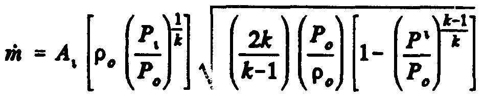
The measurement of mass flow rate of the gas according to this invention makes beneficial use of relationships of specific heat to mass of the gas and the fact that flow through a sonic nozzle is isotropic (no energy loss) to obtain accurate mass flow rate measurements of the gas, regardless of molecular composition or non-ideal gas characteristics of the gas being measured. To implement this invention, a pressure tap 304 is positioned at, or preferably slightly (a few thousandths of an inch) upstream of, the throat 446 of the nozzle 52 to get a pressure P- measurement of the fluid flowing through a cross-section I of the nozzle 52. The mass flow rate rii- of the gas through section i can be expressed by the equation:

where: p0 = density of the gas at stagnant pressure P0;
P0 = stagnant pressure of the gas just upstream of the sonic nozzle;
P; = pressure of the gas flowing through the cross-section i of the nozzle; and k = specific heat ratio of the gas (heat capacity per unit of mass). The velocity v* at the cross-section i can also be expressed in terms of p0, P0, P-, and k by applying the energy equation to get

Therefore, substituting equation (2) and (3) into equation (1) yields mass flow rate m, as follows:

Likewise, mass flow rate at the cross-section t of the smallest area or throat 446 can be expressed as
(5) if?t=P tAtvt
where: pt = gas density at the throat t;
At = cross-sectional area at the throat t; and vt = velocity of gas flow at me throat cross-section t. When the sonic nozzle is choked, the mass flow m, at the throat 446 is fixed for a particular gas temperature T and pressure P0 upstream of the nozzle 52, as explained in more detail in our U.S. Patent Nos. 5,238,030 and 5,259,424. The density pt of the gas at the throat 466 is

and the velocity Vt of the gas at the throat 466 is

where:
R = the universal gas constant; and
T0 = temperature of the gas just upstream of the nozzle.
Therefore, substituting equations (6) and (7) into equation (5) yields mass flow rate m. at the throat in terms of the formula:

Since: p
— =RTn
(state equation), equation (8) reduces to:

Since the mass flow rate m. at the throat cross-section t under choked condition is constant, the mass flow rate m- at cross-section I upstream of the throat is also constant and is the same as the mass flow rate rh, at the throat. Therefore, equations (4) and (9) can be equated to yield:

(10)
Simplifying provides a relationship among P- to P0 ratio, A, to A- ratio, and specific heat ratio k, as follows:

(ID
Therefore, since the cross-sectional areas A, and A- are fixed by the geometry of the nozzle 52 and by the placement of the pressure tap 304 in the nozzle 52, obtaining pressure measurements for P. and P0 enables a solution for specific heat ratio k from equation (11). Then, using the calculated specific heat ratio k from equation (11) along with the already measured pressures P- and P0, and also obtaining a measurement of the gas density p0 at the pressure P„, an accurate mass flow rate rh- can be calculated from equation (4), regardless of the molecular composition of the gas being dispensed. As mentioned above, the mass flow rate m- at the cross-section i is the same as the mass flow rate m. at the throat cross-section t or, for that matter, is the same as the mass flow rate rh through any section of the nozzle 52. Therefore, m- calculated for a given pressure P., a given pressure P„, and a given density p0 is a measure of the instantaneous mass flow rate m delivered to the vehicle tank 300. When the P-, P„ and p„ values are updated frequently on a real time basis, fed to a microprocessor 306, and recalculated rapidly, the resulting sequentially recalculated values of m- provide effectively real time mass flow rate m measurements of the gas dispensed to the vehicle tank 300. Multiplying mass flow rate rh by time, which can also be done rapidly at many short time intervals with the microprocessor 306, provides a cumulative or running total of the mass of gas dispensed into the vehicle tank 300 on a real time basis. The flowing pressure P* and stagnant pressure P„ can be obtained with respective state-of-the- art pressure transducers 310 and 96, which can be, for example, a 5,000 p.s.i.a pressure transducer Engineering Measurements Company of Longmont, Colorado, EG&G Chandler Enginering of P.O. Box 470710, Tulsa, Oklahoma. The gas density p0 can be obtained with a state-of-the-art densitometer 600, for example, a Model UGC 278 densitometer manufactured by EG&G Chandler
Engineering of P.O. Box 470710, Tulsa, Oklahoma, or a Model FD 700, manufactured by Sarasota Automation, Inc., of 10335 Landsbury, Suite 300, Houston, Texas, or a Model 7812 manufactured by Schlumberger Industries, Transducer Dvision, 11321 Richmond Avenue, M-102, Houston Texas, or a densitometer manufactered by Engineering Measurements Company of Longmont, Colorado. In operation, the main valve 312 at the supply tank 110 is opened to allow gas to flow through supply pipe 114 to the intake plenum 56 of the dispenser 100 of this invention. The densitometer 600 can be connected to the intake plenum 56, and density readings can be fed through a connection 318 to the microprocessor 306. From the intake plenum 56, the gas flows through an intermediate conduit 308 to the staging plenum 314, where stagnation pressure P„ is obtained through a pressure tap 316 by the P„ pressure transducer 96. A shut-off valve 320 is positioned between the supply tank 110 and the staging plenum 314 for turning the gas flow "on" and "off" in response to signals from the microprocessor 306. The pressure signals can be fed from transducers 306 and 308 via respective connections 307 and 309 to the microprocessor 306.
In the preferred embodiment dispenser 100, the shut-off valve 320 is positioned between the conduit 308 and staging plenum 314 in axial alignment with the sonic nozzle 52, as shown in Figure 1 and 6, and it is pilot operated with gas pressure from the intermediate conduit 308. The pilot gas pressure is directed by pilot supply line 340 through a solenoid-operated pilot valve 342 and then through either pilot operating line 343 or 344 to close or open the shut-off valve 320. Signals from the microprocessor 306 via a connection 345 actuate the solenoid pilot valve 342 to apply gas pressure to a pilot actuator (not shown in Figure 1) on shut-off valve 320 to close the shut-off valve 320 or to release gas pressure to open shut-off valve 320, as will be described in more detail below.
Gas is delivered from the dispenser 100 to the vehicle tank 300 by a delivery or dispenser hose 28. The dispenser hose 28 and intake pipe 346 of vehicle tank 300 have respective mating couplers 348 and 349 for connecting the dispenser hose 28 to vehicle tank 300. A valve 350, usually manually operated, is provided in the intake pipe 346 of tank 300, and a delivery valve 44, also usually manually operated, is provided on the distal end of dispenser hose 28. The proximal end of dispenser hose 28 is connected to an outlet plenum 62 positioned at the downstream end of the nozzle 52.
With couplers 348, 349 connected togeuier and the valve 350 on vehicle tank 300 opened, the delivery valve 44 can also be opened. A signal can be sent automatically via connection 352 or manually via a switch (not shown) to start the microprocessor and let it know that the couplers 348, 349 and valves 350, 44 are set for a fill operation.
The microprocessor 306 is preferably programmed to go through an initialization procedure similar to that described in our U.S. Patents Nos. 5,238,030 and 5,259,424, to calibrate the P- and
P„ pressure transducers 310 and 96 to each other. In other words, with the shut-off valve 320 still closed and with e delivery valve 44 and tank valve 350 opened, the stagnant pressures throughout e system downstream of shut-off valve 320 all the way to and including the vehicle tank 300 should equalize, so the pressure transducers 310 and 96 should read the same values. If not, the microprocessor 306 is programmed to add a correction value equal to the difference in the two transducers 310, 96 to die readings of one of diem as explained in more detail in our U.S. Patent Nos. 5,238,030 and 5,259,424. As also mentioned in our U.S. Patents Nos. 5,238,030 and 5,259,424, it might be necessary to first briefly open and men close valve 320 to pop open a one way check valve (not shown) that is usually positioned in the vehicle tank 300 in order to get a read on the initial pressure in tank 300 with pressure transducers 310 or 96.
The fill operation can be initiated with a start switch 301 or any other device that sends a start signal to d e microprocessor 306, which in turn initializes time and other functions, as described above. To start the flow of gas, the microprocessor 306 sends a signal via connection 345 to solenoid 341 to open pilot valve 342, which applies gas pressure via conduit 344 to open die shut-off valve 320, as will be described in more detail below. When the shut-off valve 320 is opened, gas flows from the supply tank 110, assuming main tank valve 312 is already open, as is the usual case after initial set up and assembly. The gas flows through inlet plenum 56, where densitometer 600 takes density ps measurements of the gas and through conduit 308 to staging plenum 314. The plenums 56 and 314 should be large enough to have substantially stagnant pressure conditions, in spite of gas flowing through them, so mat pressure P0 and density pβ measurements are at stagnant conditions. The plenums 56 and 314 should also be in close proximity to each other and to the sonic nozzle 52 to ensure that the gas for which density p0 measurements are taken is substantially the same in composition as the gas being measured in die sonic nozzle 52. With the valve 320 open, the pressure in die inlet plenum 56 should be substantially the same as the pressure P0 in staging plenum 314, so the density p0 measurement is made essentially at P0 pressure. The Ps pressure is measured by the pressure transducer 96 tapped into staging plenum 314, as described above. Actually, the density p0 reading could be taken in the staging plenum 314, and me inlet plenum 56 could be eliminated in alternately structured dispensers.
From the staging plenum 314, the gas flows into the converging section 442 of the sonic nozzle 52, through d e throat 446 and diverging section 444 of die sonic nozzle 52, and into the oudet plenum 62. As long as the ratio of pressure P2 downstream of die nozzle 52 to die pressure P. upstream of the nozzle 52 is less man critical (approximately 0.85), me flow of gas through die throat 446 is choked at sonic velocity and cannot increase. Consequendy, the flow where pressure P* is measured, which is preferably slightly upstream of die throat 446, is always subsonic. While it is
not necessary to the determination of mass flow according to this invention, when flow through the nozzle 52 is choked at sonic velocity, a pressure transducer 92 for measuring me pressure P2 at the oudet of the diffuser section 444 is tapped into oudet plenum 62 and connected to microprocessor 306 to monitor the P2/P0 ratio. If me P2/P0 rises above die critical level of about 0.85, such as near the end of a dispensing cycle when the vehicle tank 300 is almost filled, men Equation (4) above is used to calculate mass flow rate m, assuming a constant specific heat k equal to the specific heat k that was previously measured when die flow was critical, i.e., when me P2/P0 was less than about 0.85. The sensitivity of Equation (4) to specific heat k changes is very small for P2/P0 ratios greater than critical, so any changes in specific heat k during subsonic flow have a negligible effect on overall metering accuracy. Of course, die mass flow rate m determinations according to mis invention with the formula of Equation (4) above can also be made with specific heat ratio k measurements or values obtained with odier, more conventional mediods or from look-up tables after determining molecular composition of die gas, such as with a chromatograph. However, the method and apparatus for determi. g specific heat ratios k according to this invention, as described above, have die advantage of real-tim application, which is significant for natural gas, which varies in composition in different locations and even in die same locations from well to well or from time to time.
From e outiet plenum 62, the gas continues flowing tiirough dispenser hose 28 to the vehicle tank 300, as described above. At die same time, the Pβ and P* information from transducers 96 and 310 are fed to die microprocessor 306, which uses mat information along with preprogrammed area At of the throat cross-section t and area A- of d e cross-section I in converging section 442 of sonic nozzle 52 to determine the specific heat ratio k of the gas according to equation (10), as described above. The microprocessor 306 then uses the determined value of specific heat ratio k along with die measured gas density pc, stagnant pressure Pβ, flowing pressure P,, and area A- of the cross- section I to determine mass flow rate rh* according to equation (4), as described above. The microprocessor 306 can be programmed to use the specific heat k or some average of recent specific heat k values for calculating mass flow rate m with Equation (4) when die P2/P0 ratio reaches or climbs above critical (about 0.85), as described above. Of course, multiplying mass flow rate iii- times me elapsed time from any time interval yields e mass of gas flowed dirough the nozzle 52 during that interval. Real time in terms of minutes or seconds, or even fractions of seconds can be input to e microprocessor 306 by an appropriate timing device 302. The shorter me time intervals used, i.e., d e more sequential recalculations of specific heat k and mass flow measurements made during a vehicle tank fill, die more accurate will be the mass flow measurements, because the values of die parameters k, p0, P0 , and P* will be more specific and accurate for such shorter time intervals. The microprocessor 306 can also tabulate sequential mass determinations of sequential time intervals
diroughout the gas fill process to keep a real time running total of mass delivered to the vehicle tank 300. For purposes of this invention, sequential recalculations of specific heat k and mass flow measurements at time intervals on me order of milliseconds yields very accurate mass flow values. The method and apparatus of this invention can measure mass flow of natural gas being dispensed significandy more accurately man the mass flow determinations obtained by die inventions described in our U.S. Patents Nos. 5,238,030 and 5,259,424.
While this invention is directed primarily to improved mass flow measuring in gas dispensers, it is appropriate to note that d e microprocessor 306, with an additional ambient temperature or gas temperature input (not shown), can be programmed to determine me volume of the vehicle tank 300, a temperature compensated maximum pressure for the vehicle tank 300, die additional mass of gas required to fill die vehicle tank 300, to that temperature compensated maximum pressure, d e mass of gas actually dispensed, and to output a signal to die solenoid 341 to operate the pilot valve 342 to shut-off valve 320 when the mass of gas actually dispensed equals die mass required for maximum temperature compensated fill, all as described in our U.S. Patent No. 5,238,030. When die fill is complete and me shut-off valve 320 is closed, die hose valve 44 and vehicle tank valve 350 can be closed and the coupler 348, 349 disconnecting couplers 348, 349, it may be desirable to open bleed valve 390 to bleed residual gas trapped between valves 44 and 350 to a vent recovery system 391, which is well known in this art and not a part of this invention.
The electrical power supplies to the density and pressure transducers, amplifiers, filters, analog-to-digital converters, and other electric circuit components to the microprocessor connections that implement mis invention are well-known and within the capabilities of persons skilled in mat art, once me principles of this invention are understood, so they are not described in any greater detail. A number of safety features, such as those to detect broken or disconnected hoses, as described in our U.S. Patents No. 5,238,030 and 5,259,424, as well as other safety features may be used widi diis invention. However, such safety features are not a part of mis invention, so are not described in anymore detail herein.
The structures and mechanical components of the valve and fluid flow dispenser measuring apparatus according to mis invention might not be as obvious, so an exemplary embodiment is shown in Figures 2-6. A housing 303 contains the inlet plenum 56, shut-off valve 320, staging plenum 314, sonic nozzle 52, and oudet plenum 62, as best seen in Figure 6. A pipe fitting 305 sealed with an o-ring seal 307 connects the high pressure supply line 114 to me inlet plenum 56, which is bored into me upstream face 354 of housing 303. A similar pipe fitting 309 and o-ring seal 311 connects die threaded end of die dispenser hose 28 to die oudet plenum 62, which is bored into die downstream face 355 of housing 303. Therefore, me gas flows into die housing 303 from the source of supply
110 (not shown in Figures 2-6), dirough fitting 305, as indicated by arrow 313, and it flows out of housing 303 through fitting 309, as indicated by arrow 313 to vehicle tank 300 (not shown in Figures 2-6).
The densitometer 600 is connected via a duct 317 bored into the housing 303 from the top surface 353 to the inlet plenum. An annular filter 319 in plenum 56 protects the densitometer 600 from solid or liquid impurities uiat might be in die gas. The intermediate conduit 308 extends dirough e housing 303 to a valve chamber 321 that is bored into the housing 303 from die top surface 353 substantially perpendicular to die conduit 308. The valve chamber 321 is bored in four different diameter sections 322, 323, 324, 325, with die smallest section 322 extending into the oudet plenum 62.
A nozzle plug 326 with the sonic nozzle 52 extending axially therethrough is positioned in die bottom of me smaller intermediate section 323 of die valve chamber 321 and is sealed by o-ring seals 327, 328. An annular P- pressure chamber 330 is recessed into me peripheral surface of nozzle plug 326 between die o-ring seals 327, 328. The P* pressure tap 304 is bored laterally from me annular P- pressure chamber 330 dirough the nozzle plug 326 to intersect perpendicularly wiΛ the sonic nozzle 52 slightiy above die tiiroat 446. The P* pressure transducer 310 (shown only in Figure 1) is connected by a tube 332 to a P* pressure port 331 mat extends from die left side 357 of housing 303 into an intersection with die smaller intermediate section 323 of valve chamber 321 in alignment with die annular P- chamber 330. An axial recess 332 in the top of the nozzle plug 326 forms the lower part of staging plenum 314.
A cylindrical sleeve 333 with an internal axial bore 334 is positioned in the top of the smaller intermediate section of valve chamber 321 and forms the upper part of staging plenum 314. An o- ring seal 329 encircles die periphery of sleeve 333, and a tapered upper rim forms a valve seat 335. A space between the top of nozzle plug 326 and d e bottom of sleeve 333 forms an annular extension 336 of staging plenum 314. The P0 pressure tap 316 is bored laterally through housing 303 from a P„ pressure port 337 in downstream face 355 into the valve chamber 321 in alignment with the annular extension 336. The P0 pressure transducer 96 (shown only in Figure 1) is connected to port 337 via a tube 338, so die P0 pressure transducer 96 can measure the Pc pressure in staging plenum 314. A valve plunger 360 is positioned slidably in the larger intermediate section 324 of valve chamber 321 for opening and closing the staging chamber 314 to the intermediate conduit 308. A soft valve closure 361, preferably fabricated of a soft neoprene or rubber material, is adhered to a bolt 362 tiiat is screwed into the lower end of plunger 360 for seating in the valve seat 335. The lower end of plunger 360 is a narrowed neck 363 mat leaves an annular space 364 around die plunger
360 that is connected to intermediate conduit 308. A port 365 in die downstream side 355 of housing 303 connects to die annular space 364, tiius also to intermediate conduit 308, which is open to the supply gas pressure line 114. Therefore, the pilot supply tube 340 attached to port 365 always has high pressure gas, regardless of die position of valve plunger 360 in valve chamber 321. This gas pressure in pilot supply tube 340 can be supplied selectively by die 3-way pilot valve 342 (Figure 1) to eitiier die top of plunger 360 via pilot operating tube 344 and port 366 to move the plunger 360 downwardly into seat 335 or to the underside of flange 367 of plunger 360 via pilot operating tube 343 and port 368 to move the plunger 360 upwardly away from seat 335.
The pilot operated shut-off valve 320 is comprised primarily of the valve seat 335, die slidable plunger 360, and the soft closure 361, which assembly opens or closes the staging plenum 314 to intermediate conduit 308. The enlarged flange 367 on the upper end of plunger 360 fits in d e largest diameter section 325 of valve chamber 321. The annular space 369 under die flange 367 is connected to port 368 by a tap 370 bored laterally into housing 303 to me lowest part of the largest diameter section 325 of valve chamber 321. Connecting this annular space 369 to gas pressure via pilot tube 343, while bleeding pressure off die top of plunger 360 will cause the plunger 360 to move upwardly, tiius opening me value 320.
The port 366 to which the odier pilot tube 344 is connected is bored into a bonnet 371, which, along wfth seal 372, closes die top of valve chamber 321. A tap 373 connects me port 366 to the space 374 in valve chamber 321 between the top of plunger 360 and die bottom of bonnet 371. Applying gas pressure to this space 374 while bleeding pressure off die annular space 369 causes die plunger 360 to move downwardly and seat in die valve seat 335, tiius closing valve 320. Seals 375, 376 around die plunger 360 on either side of annular space 369 prevent leakage around die sides of die plunger 360.
Of course, d e valve 320 could be actuated by air pressure, by a solenoid, or by any other well-known mechanism, and does not have to be pilot gas operated for purposes of this invention. The P2 pressure transducer 92 (Figure 1) is connected by a tube 378 to a port 377 extending from the left side 357 into the oudet plenum 62.
The foregoing is considered as illustrative only of die principles of this invention. Further, since numerous modifications and changes will readily occur to those skilled in the art, it is not desired to limit me invention to the exact construction and operation shown and described, and accordingly, all suitable modifications and equivalents may be considered as falling within the scope of die invention as defined by d e claims which follow.
Claims
1. Apparatus for measuring specific heat ratio k of a gas, comprising: a sonic nozzle having a flow passage that converges from an entrance to a throat that has a cross-sectional area A, and diverges after d e throat to an exit; a staging plenum adjacent said entrance tiiat is large enough to have stagnant pressure conditions of a gas tiiat flows dirough said staging plenum, into said nozzle, and dirough said diroat at sonic choked or velocity; stagnant pressure sensing means connected to said staging plenum for measuring stagnant pressure P0 of a gas in said staging plenum; a pressure tap into said flow passage at a location having a cross-sectional area A- adjacent said throat with flow pressure transducer means connected to said pressure tap for measuring pressure P- of a gas flowing through said nozzle; and microprocessor means connected to said stagnant pressure sensing means and to said flow pressure transducer means for determining specific heat k of a gas flowing through said sonic nozzle in choked or sonic flow condition according to relationships that can be expressed by die formula:

2. The apparatus of claim 1, wherein said pressure tap is upstream of said diroat.
3. The apparatus of claim 1, including densitometer means positioned for determining density pD of said gas at stagnant pressure PD, said microprocessor means also being connected to said densitometer means and being for determining mass flow rate rh of said gas according to relationships mat can be expressed by the formula:
4. The apparatus of claim 3 , wherein said microprocessor means is programmed to make said calculations of specific heat k and mass flow rate m on a real-time basis.
5. The apparatus of claim 3 , wherein said microprocessor means is programmed to make
said calculations of specific heat k and mass flow rate rh at short sequential time intervals.
6. The apparatus of claim 3, wherein said microprocessor means is programmed to calculate mass flow over one of said time intervals by multiplying mass flow rate rh by the time interval.
7. The apparatus of claim 6, wherein said microprocessor means is programmed to calculate sequential mass flows over a plurality of said sequential time intervals and to add said sequential mass flows together to determine cumulative mass flow over the duration of said plurality of said time intervals.
8. A metiiod of determining specific heat k of a gas, comprising die steps of: flowing said gas dirough a sonic nozzle mat has a flow passage which converges from an entrance to a diroat having a cross-sectional area At and diverges from the diroat to an exit under sufficient pressure differential between said entrance and said exit to cause die gas flow to choke at sonic velocity in said diroat; measuring stagnant pressure P0 of said gas at said entrance; measuring flowing pressure P- of said gas at a location in said flow passage having a cross-sectional area A-; and determining specific heat k of said gas according to relationships that can be expressed by die formula:

9. The method of claim 8, wherein said step of measuring flowing pressure P* is done at a location that is in the converging portion of said flow passage slighdy upstream of said diroat.
10. A method of measuring mass flow of a gas, comprising the steps of: flowing said gas dirough a nozzle that has a flow passage which converges from an entrance to a diroat mat has a cross-sectional area A, and diverges from the diroat to an exit under sufficient pressure differential between said entrance and said exit to cause die gas flow to choke at sonic velocity in said diroat; measuring stagnant pressure P„ of said gas at said entrance; measuring flow passage pressure P* of said gas at a location in said flow passage having a cross-sectional area A-; determining specific heat k of said gas according to relationships that can be expressed by d e formula:

measuring density of said gas at said stagnant pressure P0; and deteirnining mass flow rate m of said flow of gas according to relationships mat can be expressed by the formula:

11. The method of claim 10, wherein said step of measuring flow passage pressure Pi is done at a location in the converging portion of said flow passage mat is upstream from said throat.
12. The method of claim 11, including die steps of measuring said stagnant pressure P0 and said flow passage pressure P. and making said determination of specific heat k on a real time basis.
13. The method of claim 11, wherein said step of measuring flow passage pressure P* is done at a location in me converging portion of said flow passage tiiat is closer to said diroat man to said entrance.
14. The method of claim 12, including the steps of measuring density pβ of said gas at said stagnant pressure P0 and determining said mass flow rate m on a real time basis.
15. The method of claim 10, including the steps of measuring said stagnant pressure P0, flow passage pressure P-, and density p0 at sequential time intervals while said gas is flowing and using said Pβ, P-, and pc measurements to determine specific heat k and mass flow rate m at sequential time intervals.
16. The method of claim 15, including die steps of determining mass m of gas that flows in each of die intervals by multiplying mass flow rate m determined for each time interval by die time elapsed in die time interval.
17. The method of claim 16, including die step of determining accumulated mass of gas mat flows over an extended time period by adding die incremental mass determinations for each time interval in the extended time period.
18. A method of measuring mass flow rate of a flowing gas mat varies in aggregate molecular composition, comprising me steps of : deteπnining specific heat ratio k of the gas;
determining mass flow rate rii of die flowing gas as a function of die specific heat ratio k of die gas; redetermining specific heat ratio k of die gas as molecular composition of the gas varies; and redetermining mass flow rate m of the flowing gas as a function of die redetermined specific heat ratio k of die gas.
19. The method of claim 18, including die steps of determining the specific heat ratio k by flowing die gas dirough a conduit that includes a nozzle which converges from a wider cross- section of said conduit to a narrower diroat section such tiiat there is a pressure differential between the gas in said closed conduit upstream of said nozzle and die gas in said nozzle, measuring the respective pressures upstream of said nozzle and in said nozzle, and determining said specific heat ratio of said gas as a function of the ratio of said pressure in said nozzle to die pressure upstream of the nozzle.
20. The method of claim 19, including die steps of flowing said gas through said nozzle under conditions of sonic velocity choked flow in said nozzle.
21. The method of claim 20, including the step of measuring said pressure in said nozzle upstream of said diroat.
22. The method of claim 21, including die steps of measuring said pressure upstream of " said nozzle under substantially stagnant condition.
23. The method of claim 22, including die step of measuring density of said gas at die stagnant pressure condition and determining me mass flow rate m as a function of said density, said ratio of pressure in die nozzle to pressure upstream of the nozzle, and said specific heat ratio k.
24. A method of determining specific heat ratio k of a gas, comprising the steps of flowing the gas dirough a conduit tiiat includes a nozzle which converges from a wider cross-section of said conduit to a narrower diroat section such tiiat tiiere is a pressure differential between the gas in said closed conduit upstream of said nozzle and die gas in said nozzle; measuring the respective pressures upstream of said nozzle and in said nozzle and determining said specific heat ratio of said gas as a function of die ratio of said pressure in said nozzle to die pressure upstream of the nozzle.
25. The method of claim 24, including d e steps of flowing said gas dirough said nozzle under conditions of sonic velocity choked flow in said nozzle.
26. The method of claim 27, including die step of measuring said pressure in said nozzle upstream of said diroat.
27. The method of claim 26, including die steps of measuring said pressure upstream of said nozzle under substantially stagnant condition.
28. The method of claim 27, including die step of deteπnining said specific heat ratio k of said gas according to relationships mat can be expressed by die formula:

where P* is said pressure in said nozzle, P0 is said pressure upstream of said nozzle, At is die cross- sectional area of said diroat section, and A- is die cross-sectional area of die nozzle at the location where said pressure Pi in said nozzle is measured.
Priority Applications (1)
| Application Number | Priority Date | Filing Date | Title |
|---|---|---|---|
| AU25562/95A AU2556295A (en) | 1994-05-25 | 1995-05-25 | Density compensated gas flow meter |
Applications Claiming Priority (2)
| Application Number | Priority Date | Filing Date | Title |
|---|---|---|---|
| US08/248,689 US5564306A (en) | 1994-05-25 | 1994-05-25 | Density compensated gas flow meter |
| US08/248,689 | 1994-05-25 |
Publications (1)
| Publication Number | Publication Date |
|---|---|
| WO1995032405A1 true WO1995032405A1 (en) | 1995-11-30 |
Family
ID=22940246
Family Applications (1)
| Application Number | Title | Priority Date | Filing Date |
|---|---|---|---|
| PCT/US1995/006633 WO1995032405A1 (en) | 1994-05-25 | 1995-05-25 | Density compensated gas flow meter |
Country Status (3)
| Country | Link |
|---|---|
| US (1) | US5564306A (en) |
| AU (1) | AU2556295A (en) |
| WO (1) | WO1995032405A1 (en) |
Cited By (6)
| Publication number | Priority date | Publication date | Assignee | Title |
|---|---|---|---|---|
| GB2335281A (en) * | 1998-03-13 | 1999-09-15 | Standard Aero Limited | Gas flow are measurement |
| AU753256B2 (en) * | 1998-03-13 | 2002-10-10 | Standard Aero Limited | Gas flow area measurement |
| US6772627B2 (en) | 2002-03-26 | 2004-08-10 | Ronald J. Fleming | Flow vector analyzer for flow bench |
| US7024929B2 (en) | 2002-03-25 | 2006-04-11 | Fleming Ronald J | Flow stabilizer for flow bench |
| WO2009143447A1 (en) * | 2008-05-23 | 2009-11-26 | Rosemount, Inc. | Multivariable process fluid flow device with energy flow calculation |
| WO2018111725A1 (en) * | 2016-12-15 | 2018-06-21 | Mks Instruments, Inc. | Methods and apparatus for wide range mass flow verification |
Families Citing this family (44)
| Publication number | Priority date | Publication date | Assignee | Title |
|---|---|---|---|---|
| DE69802954T4 (en) | 1997-10-02 | 2003-11-20 | Siemens Canada Ltd | METHOD FOR TEMPERATURE CORRECTION AND SUBSYSTEM FOR AN ARRANGEMENT FOR EVAPORATION LEAK DETECTION OF VEHICLES |
| KR100362819B1 (en) * | 1998-01-16 | 2002-11-29 | 비지 인텔렉츄얼 프라퍼티 리미티드 | Method and apparatus for measuring the relative density of a gas |
| US6343505B1 (en) | 1998-03-27 | 2002-02-05 | Siemens Canada Limited | Automotive evaporative leak detection system |
| US6450153B1 (en) | 1999-11-19 | 2002-09-17 | Siemens Canada Limited | Integrated pressure management apparatus providing an on-board diagnostic |
| US6478045B1 (en) | 1999-11-19 | 2002-11-12 | Siemens Canada Limited | Solenoid for an integrated pressure management apparatus |
| US6983641B1 (en) | 1999-11-19 | 2006-01-10 | Siemens Vdo Automotive Inc. | Method of managing pressure in a fuel system |
| US6470861B1 (en) | 1999-11-19 | 2002-10-29 | Siemens Canada Limited | Fluid flow through an integrated pressure management apparatus |
| US6502560B1 (en) | 1999-11-19 | 2003-01-07 | Siemens Canada Limited | Integrated pressure management apparatus having electronic control circuit |
| US6460566B1 (en) | 1999-11-19 | 2002-10-08 | Siemens Canada Limited | Integrated pressure management system for a fuel system |
| US6505514B1 (en) | 1999-11-19 | 2003-01-14 | Siemens Canada Limited | Sensor arrangement for an integrated pressure management apparatus |
| US6484555B1 (en) | 1999-11-19 | 2002-11-26 | Siemens Canada Limited | Method of calibrating an integrated pressure management apparatus |
| US6470908B1 (en) | 1999-11-19 | 2002-10-29 | Siemens Canada Limited | Pressure operable device for an integrated pressure management apparatus |
| US6453942B1 (en) | 1999-11-19 | 2002-09-24 | Siemens Canada Limited | Housing for integrated pressure management apparatus |
| US6474313B1 (en) | 1999-11-19 | 2002-11-05 | Siemens Canada Limited | Connection between an integrated pressure management apparatus and a vapor collection canister |
| US6474314B1 (en) | 1999-11-19 | 2002-11-05 | Siemens Canada Limited | Fuel system with intergrated pressure management |
| NL1014032C2 (en) * | 2000-01-07 | 2001-07-10 | Ir T Hendriks B V | Method and device for measuring the flow rate of steam flowing through a pipe. |
| US6931919B2 (en) | 2001-06-29 | 2005-08-23 | Siemens Vdo Automotive Inc. | Diagnostic apparatus and method for an evaporative control system including an integrated pressure management apparatus |
| US6708552B2 (en) | 2001-06-29 | 2004-03-23 | Siemens Automotive Inc. | Sensor arrangement for an integrated pressure management apparatus |
| US20030187606A1 (en) * | 2001-12-13 | 2003-10-02 | Curry Jimmie L. | Method and apparatus for a combustionless BTU measurement meter |
| AR041013A1 (en) * | 2002-12-04 | 2005-04-27 | Yt Ingenieria Ltda | GAS DOSING DEVICE AND METHOD FOR DOSING DEFAULT GAS QUANTITIES |
| US6948481B2 (en) * | 2003-03-07 | 2005-09-27 | Siemens Vdo Automotive Inc. | Electrical connections for an integrated pressure management apparatus |
| US7350604B2 (en) * | 2004-03-04 | 2008-04-01 | Ford Global Technologies, Llc | Gaseous fuel system for automotive vehicle |
| EP1836467B1 (en) * | 2005-01-10 | 2012-04-25 | Mocon, Inc. | Instrument and method for detecting leaks in hermetically sealed packaging |
| US7578170B2 (en) | 2005-02-02 | 2009-08-25 | Mocon, Inc. | Instrument and method for detecting and reporting the size of leaks in hermetically sealed packaging |
| WO2006088542A2 (en) | 2005-02-14 | 2006-08-24 | Mocon, Inc. | Detecting and reporting the location of a leak in hermetically sealed packaging |
| FR2890167B1 (en) * | 2005-08-26 | 2007-11-23 | Ion Beam Services Sa | MASS MEASUREMENT DEVICE BY SUMMATION |
| DE102006006585B3 (en) * | 2006-02-13 | 2007-10-18 | Samson Ag | Converter of an electrical input signal into a pneumatic output signal |
| US7252014B1 (en) | 2006-04-17 | 2007-08-07 | Mocon, Inc. | Instrument and method for measuring the volume of a hermetically sealed variable volume and pressure conforming container |
| US7654131B2 (en) * | 2006-06-14 | 2010-02-02 | Mocon, Inc. | Instrument for accurately measuring mass flow rate of a fluid pumped from a hermetically sealed container |
| US20120042721A1 (en) * | 2008-02-28 | 2012-02-23 | Tareq Nasser Al-Buaijan | Partial stroke testing system coupled with fuel control valve |
| US8534327B2 (en) * | 2009-11-16 | 2013-09-17 | Toyota Jidosha Kabushiki Kaisha | Gas charging apparatus and gas charging method |
| US9212783B2 (en) | 2010-04-21 | 2015-12-15 | Honda Motor Co., Ltd. | Method and system for tank refilling |
| US9605804B2 (en) | 2010-04-21 | 2017-03-28 | Honda Motor Co., Ltd. | Method and system for tank refilling using active fueling speed control |
| US9347614B2 (en) | 2010-04-21 | 2016-05-24 | Honda Motor Co., Ltd. | Method and system for tank refilling using active fueling speed control |
| US8783303B2 (en) | 2010-04-21 | 2014-07-22 | Ryan HARTY | Method and system for tank refilling |
| US9347612B2 (en) | 2010-04-21 | 2016-05-24 | Honda Motor Co., Ltd. | Method and system for tank refilling using active fueling speed control |
| US8973624B2 (en) * | 2011-01-27 | 2015-03-10 | GM Global Technology Operations LLC | Compressed hydrogen fueling control valve |
| KR101199105B1 (en) * | 2012-05-30 | 2012-11-08 | 윤정중 | gas discharge measuring program and its measuring method |
| DE102014015555B3 (en) * | 2014-10-22 | 2015-11-19 | Bundesrepublik Deutschland, vertr. durch das Bundesministerium für Wirtschaft und Energie, dieses vertreten durch den Präsidenten der Physikalisch-Technischen Bundesanstalt | Method for detecting the criticality of a differential pressure device and device for embodying a flow |
| US10077998B2 (en) | 2015-09-14 | 2018-09-18 | Honda Motor Co., Ltd. | Hydrogen fueling with integrity checks |
| US11313514B2 (en) | 2018-12-04 | 2022-04-26 | Honda Motor Co., Ltd. | Method and system for tank refueling using dispenser and nozzle readings |
| US11339926B2 (en) | 2018-12-05 | 2022-05-24 | Honda Motor Co., Ltd. | Methods and systems for improving hydrogen refueling |
| DE102019134643A1 (en) * | 2019-12-17 | 2021-06-17 | Bayerische Motoren Werke Aktiengesellschaft | Pressure vessel system and energy supply arrangement |
| US11629821B1 (en) | 2022-01-19 | 2023-04-18 | Praxair Technology, Inc. | Gas dosing apparatus with directional control valve |
Citations (3)
| Publication number | Priority date | Publication date | Assignee | Title |
|---|---|---|---|---|
| US1208494A (en) * | 1910-04-28 | 1916-12-12 | Frederick N Connet | Fluid-meter. |
| US2183374A (en) * | 1938-01-07 | 1939-12-12 | William C Walker | Fluid meter |
| US3073158A (en) * | 1959-02-09 | 1963-01-15 | Rotron Mfg Co | Gas mass metering device |
Family Cites Families (10)
| Publication number | Priority date | Publication date | Assignee | Title |
|---|---|---|---|---|
| US3719196A (en) * | 1970-05-06 | 1973-03-06 | Jones R Mc | Charging sequence system and process |
| US4153083A (en) * | 1971-12-15 | 1979-05-08 | Jacques Imler | Process and arrangement for filling gas cylinders |
| US3799218A (en) * | 1972-03-27 | 1974-03-26 | M Douglass | Apparatus for dispensing compressed gas at programmed pressure and volume |
| US3875955A (en) * | 1974-01-10 | 1975-04-08 | Process Systems | Digital fluid flow rate measurement or control system |
| US4527600A (en) * | 1982-05-05 | 1985-07-09 | Rockwell International Corporation | Compressed natural gas dispensing system |
| US4483376A (en) * | 1982-09-07 | 1984-11-20 | Bresie Don A | Natural gas loading station |
| US4582100A (en) * | 1982-09-30 | 1986-04-15 | Aga, A.B. | Filling of acetylene cylinders |
| WO1985002244A1 (en) * | 1983-11-16 | 1985-05-23 | Metal Box Public Limited Company | A method of and apparatus for filling a container with gas |
| EP0300222B1 (en) * | 1987-07-23 | 1992-08-12 | GebràDer Sulzer Aktiengesellschaft | Filling device for a gaseous-fuel reservoir |
| NZ229839A (en) * | 1988-08-15 | 1992-01-29 | Sulzer Ag | Cng refueller with temperature and pressure cut-offs |
-
1994
- 1994-05-25 US US08/248,689 patent/US5564306A/en not_active Expired - Fee Related
-
1995
- 1995-05-25 WO PCT/US1995/006633 patent/WO1995032405A1/en active Application Filing
- 1995-05-25 AU AU25562/95A patent/AU2556295A/en not_active Abandoned
Patent Citations (3)
| Publication number | Priority date | Publication date | Assignee | Title |
|---|---|---|---|---|
| US1208494A (en) * | 1910-04-28 | 1916-12-12 | Frederick N Connet | Fluid-meter. |
| US2183374A (en) * | 1938-01-07 | 1939-12-12 | William C Walker | Fluid meter |
| US3073158A (en) * | 1959-02-09 | 1963-01-15 | Rotron Mfg Co | Gas mass metering device |
Cited By (12)
| Publication number | Priority date | Publication date | Assignee | Title |
|---|---|---|---|---|
| GB2335281A (en) * | 1998-03-13 | 1999-09-15 | Standard Aero Limited | Gas flow are measurement |
| GB2335281B (en) * | 1998-03-13 | 2000-03-08 | Standard Aero Limited | Gas flow area measurement |
| US6148677A (en) * | 1998-03-13 | 2000-11-21 | Standard Aero Limited | Gas flow area measurement |
| AU753256B2 (en) * | 1998-03-13 | 2002-10-10 | Standard Aero Limited | Gas flow area measurement |
| US7024929B2 (en) | 2002-03-25 | 2006-04-11 | Fleming Ronald J | Flow stabilizer for flow bench |
| US6772627B2 (en) | 2002-03-26 | 2004-08-10 | Ronald J. Fleming | Flow vector analyzer for flow bench |
| US6923051B2 (en) | 2002-03-26 | 2005-08-02 | Ronald J. Fleming | Flow vector analyzer for flow bench |
| WO2009143447A1 (en) * | 2008-05-23 | 2009-11-26 | Rosemount, Inc. | Multivariable process fluid flow device with energy flow calculation |
| CN102027333B (en) * | 2008-05-23 | 2012-10-03 | 罗斯蒙德公司 | Multivariable process fluid flow device with energy flow calculation |
| US8849589B2 (en) | 2008-05-23 | 2014-09-30 | Rosemount Inc. | Multivariable process fluid flow device with energy flow calculation |
| WO2018111725A1 (en) * | 2016-12-15 | 2018-06-21 | Mks Instruments, Inc. | Methods and apparatus for wide range mass flow verification |
| US10031004B2 (en) | 2016-12-15 | 2018-07-24 | Mks Instruments, Inc. | Methods and apparatus for wide range mass flow verification |
Also Published As
| Publication number | Publication date |
|---|---|
| US5564306A (en) | 1996-10-15 |
| AU2556295A (en) | 1995-12-18 |
Similar Documents
| Publication | Publication Date | Title |
|---|---|---|
| US5564306A (en) | Density compensated gas flow meter | |
| US5315862A (en) | Flow meter | |
| US5653269A (en) | Method and apparatus for multiple-channel dispensing of natural gas | |
| EP0093275B1 (en) | Compressed natural gas dispensing system | |
| US4646940A (en) | Method and apparatus for accurately measuring volume of gas flowing as a result of differential pressure | |
| AU715786B2 (en) | Flow compensated pressure control system | |
| US5483838A (en) | Fluid flow connector and gauge assembly | |
| AU677438B2 (en) | Method and apparatus for the rapid tanking of a pressure container with a gaseous medium | |
| US5316057A (en) | Vapor recovery system tester | |
| US5557965A (en) | Pipeline leak detector | |
| BRPI0621236A2 (en) | system for determining the amount of fluid expended to operate a process control system, for measuring the amount of a supply fluid spent controlling a process control system, for measuring the amount of an operating fluid expended for a control device. process control of a control system, to measure the consumption of an operating fluid, to measure the consumption of a fluid supply and to test fluid consumption of a process control device, process for determining the amount of fluid expended to operating a process control device of a control system, and method for measuring the fluid consumption required to operate a component of a fluid consuming system | |
| JP2001508740A (en) | Steam recovery system for fuel dispensers | |
| US5551282A (en) | Method and apparatus for measuring volume correction using molar quantities | |
| US6062066A (en) | Method for determining empty volume of fuel tank | |
| US20170336233A1 (en) | Method for determining a gas amount and device for carrying out said method | |
| JPH05509160A (en) | Liquefied gas metering system | |
| US5787916A (en) | Pressure testing assembly for propane tank systems and testing method | |
| KR100466317B1 (en) | Liquid measuring equipment | |
| US1887400A (en) | Meter compensating device | |
| JPH0246090B2 (en) | ||
| JP2702465B2 (en) | Dispenser for filling CNG | |
| JPH07270211A (en) | Liquified-gas measuring apparatus | |
| US3217540A (en) | Fuel gauge | |
| SU356474A1 (en) | STAND FOR VERIFICATION OF FLOWMETERS AND COUNTER FLUID | |
| CA2165586C (en) | Fluid flow connector and gauge assembly |
Legal Events
| Date | Code | Title | Description |
|---|---|---|---|
| AK | Designated states |
Kind code of ref document: A1 Designated state(s): AM AT AU BB BG BR BY CA CH CN CZ DE DK EE ES FI GB GE HU JP KE KG KP KR KZ LK LR LT LU LV MD MG MN MW MX NO NZ PL PT RO RU SD SE SG SI SK TJ TT UA UG UZ VN |
|
| AL | Designated countries for regional patents |
Kind code of ref document: A1 Designated state(s): KE MW SD SZ UG AT BE CH DE DK ES FR GB GR IE IT LU MC NL PT SE BF BJ CF CG CI CM GA GN ML MR NE SN TD TG |
|
| 121 | Ep: the epo has been informed by wipo that ep was designated in this application | ||
| DFPE | Request for preliminary examination filed prior to expiration of 19th month from priority date (pct application filed before 20040101) | ||
| REG | Reference to national code |
Ref country code: DE Ref legal event code: 8642 |
|
| 122 | Ep: pct application non-entry in european phase | ||
| NENP | Non-entry into the national phase |
Ref country code: CA |