US9817243B2 - Imaging apparatus - Google Patents
Imaging apparatus Download PDFInfo
- Publication number
- US9817243B2 US9817243B2 US14/606,565 US201514606565A US9817243B2 US 9817243 B2 US9817243 B2 US 9817243B2 US 201514606565 A US201514606565 A US 201514606565A US 9817243 B2 US9817243 B2 US 9817243B2
- Authority
- US
- United States
- Prior art keywords
- lens
- image plane
- imaging apparatus
- optical axis
- focal
- Prior art date
- Legal status (The legal status is an assumption and is not a legal conclusion. Google has not performed a legal analysis and makes no representation as to the accuracy of the status listed.)
- Active, expires
Links
- 238000003384 imaging method Methods 0.000 title claims description 42
- 230000003287 optical effect Effects 0.000 claims abstract description 85
- 230000006641 stabilisation Effects 0.000 claims abstract description 42
- 238000011105 stabilization Methods 0.000 claims abstract description 42
- 230000004044 response Effects 0.000 claims description 10
- 230000009471 action Effects 0.000 abstract description 3
- 238000000034 method Methods 0.000 description 15
- 230000006870 function Effects 0.000 description 8
- 230000000694 effects Effects 0.000 description 6
- 238000004891 communication Methods 0.000 description 5
- 230000000644 propagated effect Effects 0.000 description 5
- 230000004075 alteration Effects 0.000 description 4
- 230000008901 benefit Effects 0.000 description 4
- 238000010586 diagram Methods 0.000 description 4
- 239000003381 stabilizer Substances 0.000 description 4
- 238000004590 computer program Methods 0.000 description 3
- 239000012190 activator Substances 0.000 description 2
- 238000003491 array Methods 0.000 description 2
- 238000005516 engineering process Methods 0.000 description 2
- 230000008569 process Effects 0.000 description 2
- 230000000087 stabilizing effect Effects 0.000 description 2
- XUIMIQQOPSSXEZ-UHFFFAOYSA-N Silicon Chemical compound [Si] XUIMIQQOPSSXEZ-UHFFFAOYSA-N 0.000 description 1
- 230000004913 activation Effects 0.000 description 1
- 230000005540 biological transmission Effects 0.000 description 1
- 210000000988 bone and bone Anatomy 0.000 description 1
- 238000001514 detection method Methods 0.000 description 1
- 230000004048 modification Effects 0.000 description 1
- 238000012986 modification Methods 0.000 description 1
- 238000007639 printing Methods 0.000 description 1
- 230000001902 propagating effect Effects 0.000 description 1
- 210000003813 thumb Anatomy 0.000 description 1
- 230000007723 transport mechanism Effects 0.000 description 1
Images


Classifications
-
- G—PHYSICS
- G02—OPTICS
- G02B—OPTICAL ELEMENTS, SYSTEMS OR APPARATUS
- G02B27/00—Optical systems or apparatus not provided for by any of the groups G02B1/00 - G02B26/00, G02B30/00
- G02B27/64—Imaging systems using optical elements for stabilisation of the lateral and angular position of the image
- G02B27/646—Imaging systems using optical elements for stabilisation of the lateral and angular position of the image compensating for small deviations, e.g. due to vibration or shake
-
- G—PHYSICS
- G02—OPTICS
- G02B—OPTICAL ELEMENTS, SYSTEMS OR APPARATUS
- G02B27/00—Optical systems or apparatus not provided for by any of the groups G02B1/00 - G02B26/00, G02B30/00
- G02B27/0025—Optical systems or apparatus not provided for by any of the groups G02B1/00 - G02B26/00, G02B30/00 for optical correction, e.g. distorsion, aberration
-
- G—PHYSICS
- G02—OPTICS
- G02B—OPTICAL ELEMENTS, SYSTEMS OR APPARATUS
- G02B7/00—Mountings, adjusting means, or light-tight connections, for optical elements
- G02B7/02—Mountings, adjusting means, or light-tight connections, for optical elements for lenses
- G02B7/023—Mountings, adjusting means, or light-tight connections, for optical elements for lenses permitting adjustment
-
- G—PHYSICS
- G03—PHOTOGRAPHY; CINEMATOGRAPHY; ANALOGOUS TECHNIQUES USING WAVES OTHER THAN OPTICAL WAVES; ELECTROGRAPHY; HOLOGRAPHY
- G03B—APPARATUS OR ARRANGEMENTS FOR TAKING PHOTOGRAPHS OR FOR PROJECTING OR VIEWING THEM; APPARATUS OR ARRANGEMENTS EMPLOYING ANALOGOUS TECHNIQUES USING WAVES OTHER THAN OPTICAL WAVES; ACCESSORIES THEREFOR
- G03B3/00—Focusing arrangements of general interest for cameras, projectors or printers
- G03B3/10—Power-operated focusing
-
- G—PHYSICS
- G03—PHOTOGRAPHY; CINEMATOGRAPHY; ANALOGOUS TECHNIQUES USING WAVES OTHER THAN OPTICAL WAVES; ELECTROGRAPHY; HOLOGRAPHY
- G03B—APPARATUS OR ARRANGEMENTS FOR TAKING PHOTOGRAPHS OR FOR PROJECTING OR VIEWING THEM; APPARATUS OR ARRANGEMENTS EMPLOYING ANALOGOUS TECHNIQUES USING WAVES OTHER THAN OPTICAL WAVES; ACCESSORIES THEREFOR
- G03B5/00—Adjustment of optical system relative to image or object surface other than for focusing
- G03B5/06—Swinging lens about normal to the optical axis
-
- H—ELECTRICITY
- H04—ELECTRIC COMMUNICATION TECHNIQUE
- H04M—TELEPHONIC COMMUNICATION
- H04M1/00—Substation equipment, e.g. for use by subscribers
- H04M1/02—Constructional features of telephone sets
- H04M1/0202—Portable telephone sets, e.g. cordless phones, mobile phones or bar type handsets
- H04M1/026—Details of the structure or mounting of specific components
- H04M1/0264—Details of the structure or mounting of specific components for a camera module assembly
-
- H—ELECTRICITY
- H04—ELECTRIC COMMUNICATION TECHNIQUE
- H04N—PICTORIAL COMMUNICATION, e.g. TELEVISION
- H04N23/00—Cameras or camera modules comprising electronic image sensors; Control thereof
- H04N23/50—Constructional details
- H04N23/55—Optical parts specially adapted for electronic image sensors; Mounting thereof
-
- H—ELECTRICITY
- H04—ELECTRIC COMMUNICATION TECHNIQUE
- H04N—PICTORIAL COMMUNICATION, e.g. TELEVISION
- H04N23/00—Cameras or camera modules comprising electronic image sensors; Control thereof
- H04N23/57—Mechanical or electrical details of cameras or camera modules specially adapted for being embedded in other devices
-
- H—ELECTRICITY
- H04—ELECTRIC COMMUNICATION TECHNIQUE
- H04N—PICTORIAL COMMUNICATION, e.g. TELEVISION
- H04N23/00—Cameras or camera modules comprising electronic image sensors; Control thereof
- H04N23/60—Control of cameras or camera modules
-
- H—ELECTRICITY
- H04—ELECTRIC COMMUNICATION TECHNIQUE
- H04N—PICTORIAL COMMUNICATION, e.g. TELEVISION
- H04N23/00—Cameras or camera modules comprising electronic image sensors; Control thereof
- H04N23/60—Control of cameras or camera modules
- H04N23/68—Control of cameras or camera modules for stable pick-up of the scene, e.g. compensating for camera body vibrations
- H04N23/682—Vibration or motion blur correction
- H04N23/685—Vibration or motion blur correction performed by mechanical compensation
- H04N23/687—Vibration or motion blur correction performed by mechanical compensation by shifting the lens or sensor position
-
- H04N5/2254—
-
- H04N5/2257—
-
- H04N5/23248—
-
- H04N5/23287—
-
- G—PHYSICS
- G02—OPTICS
- G02B—OPTICAL ELEMENTS, SYSTEMS OR APPARATUS
- G02B13/00—Optical objectives specially designed for the purposes specified below
- G02B13/001—Miniaturised objectives for electronic devices, e.g. portable telephones, webcams, PDAs, small digital cameras
- G02B13/0015—Miniaturised objectives for electronic devices, e.g. portable telephones, webcams, PDAs, small digital cameras characterised by the lens design
- G02B13/002—Miniaturised objectives for electronic devices, e.g. portable telephones, webcams, PDAs, small digital cameras characterised by the lens design having at least one aspherical surface
- G02B13/003—Miniaturised objectives for electronic devices, e.g. portable telephones, webcams, PDAs, small digital cameras characterised by the lens design having at least one aspherical surface having two lenses
-
- G—PHYSICS
- G02—OPTICS
- G02B—OPTICAL ELEMENTS, SYSTEMS OR APPARATUS
- G02B5/00—Optical elements other than lenses
- G02B5/20—Filters
- G02B5/208—Filters for use with infrared or ultraviolet radiation, e.g. for separating visible light from infrared and/or ultraviolet radiation
-
- G—PHYSICS
- G03—PHOTOGRAPHY; CINEMATOGRAPHY; ANALOGOUS TECHNIQUES USING WAVES OTHER THAN OPTICAL WAVES; ELECTROGRAPHY; HOLOGRAPHY
- G03B—APPARATUS OR ARRANGEMENTS FOR TAKING PHOTOGRAPHS OR FOR PROJECTING OR VIEWING THEM; APPARATUS OR ARRANGEMENTS EMPLOYING ANALOGOUS TECHNIQUES USING WAVES OTHER THAN OPTICAL WAVES; ACCESSORIES THEREFOR
- G03B2205/00—Adjustment of optical system relative to image or object surface other than for focusing
- G03B2205/0007—Movement of one or more optical elements for control of motion blur
- G03B2205/0023—Movement of one or more optical elements for control of motion blur by tilting or inclining one or more optical elements with respect to the optical axis
-
- G—PHYSICS
- G03—PHOTOGRAPHY; CINEMATOGRAPHY; ANALOGOUS TECHNIQUES USING WAVES OTHER THAN OPTICAL WAVES; ELECTROGRAPHY; HOLOGRAPHY
- G03B—APPARATUS OR ARRANGEMENTS FOR TAKING PHOTOGRAPHS OR FOR PROJECTING OR VIEWING THEM; APPARATUS OR ARRANGEMENTS EMPLOYING ANALOGOUS TECHNIQUES USING WAVES OTHER THAN OPTICAL WAVES; ACCESSORIES THEREFOR
- G03B29/00—Combinations of cameras, projectors or photographic printing apparatus with non-photographic non-optical apparatus, e.g. clocks or weapons; Cameras having the shape of other objects
Definitions
- Digital cameras usually comprise a lens and a sensor for capturing an image by capturing light and converting it into electrical signals.
- Mobile electronic devices such as smart phones are usually equipped with an imaging apparatus, a camera.
- the imaging quality of the hand-held devices may be improved by optical image stabilization.
- a camera lens usually provides sharp focus on only a single plane. When the lens plane is tilted relative to the image plane, the focus plane is at an angle to the image plane, causing blurring near the edges of the image captured from the image plane.
- the lens arrangement has at least two lenses, wherein a first lens may be used for autofocus and optical image stabilization.
- the first lens is tilted to compensate for the shaking movement of the hand-held device and to stabilize the image to be captured on the image plane.
- the tilt action may occur in two degrees of freedom, wherein an actuator causes the first lens to tilt around a pivot.
- a second lens is a field flattener lens that compensates for the error caused by the difference between the image plane and the focus plane.
- the field flattener lens causes the focal plane of the first lens to lie in the image plane when the first lens is in a tilted position.
- FIG. 1 is a schematic diagram of one example of an electronic device incorporating an imaging apparatus
- FIG. 2 is a schematic diagram of one example of an imaging apparatus having a first lens arranged on an optical axis;
- FIG. 3 is a schematic diagram of one example of an imaging apparatus having a first lens and a second lens arranged on an optical axis;
- FIG. 4 is a schematic diagram illustrating the effect of a prism in tilted position
- FIG. 5 a illustrates an exemplary scenario of tilt-enabled optical image stabilization with two lens groups
- FIG. 5 b illustrates an exemplary scenario of tilt-enabled optical image stabilization with two lens groups
- FIG. 5 c illustrates an exemplary scenario of tilt-enabled optical image stabilization with two lens groups
- FIG. 5 d illustrates an exemplary scenario of tilt-enabled optical image stabilization with two lens groups
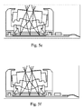
- FIG. 5 e illustrates an exemplary scenario of tilt-enabled optical image stabilization with two lens groups
- FIG. 5 f illustrates an exemplary scenario of tilt-enabled optical image stabilization with two lens groups.
- the present examples are described and illustrated herein as being implemented in a smartphone, the device described is provided as an example and not a limitation. As those skilled in the art will appreciate, the present examples are suitable for application in a variety of different types of mobile and/or hand-held apparatuses, e.g. in tablets, laptops or gaming consoles.
- FIG. 1 shows one example of an electronic device incorporating an imaging apparatus, wherein one embodiment of the electronic device is a smartphone.
- the electronic device comprises a body 100 comprising a display 110 , a speaker 120 , a microphone 130 and keys 140 .
- the electronic device comprises an imaging apparatus 150 , a camera on one surface.
- the electronic device may comprise two or more cameras, for example one on the front surface 150 and one on the rear surface 160 . Cameras may be different; some cameras may be equipped with optical image stabilization, whereas some cameras may lack certain features.
- FIG. 2 shows one example of an imaging apparatus 210 having a first lens 211 arranged on an optical axis.
- the optical axis is a line along which there is some degree of rotational symmetry in an optical system.
- the optical axis is an imaginary line that defines the path along which light propagates through the system.
- the first lens 211 is arranged in a lens barrel 220 as a part of a first lens group 212 .
- the first lens group 212 inside the lens barrel 220 may operate an autofocus function, a zoom and the optical image stabilization.
- the optical image stabilization is achieved by tilting the lens barrel 220 in the direction that reduces the effect of detected shaking.
- the lens barrel 220 is attached to an actuator 221 that tilts the lens barrel.
- An image plane 230 is arranged on the optical axis to receive the image from the lens barrel 220 .
- a focal plane 240 is the plane where object appears in focus.
- the tilted lens barrel 220 causes the focal plane 240 to tilt as well, wherein the focal plane 240 and the image plane are not aligned.
- the image plane 230 comprises for example a plurality of light sensing elements that measure the light captured by the light sensing elements to form an image of pixels.
- the focal plane projection error 241 increases towards the edges of the image plane and the edges of the image captured on the image plane 230 may be blurred.
- FIG. 3 discloses another example of an imaging apparatus.
- the first lens 311 is arranged on the lens barrel 320 , wherein the cylindrical shape of the wall defines the cylindrical shape of the lens barrel 320 .
- the first lens may also be arranged in other forms than the lens barrel 320 .
- the first lens 311 may be part of a first lens group 312 arranged in the lens barrel, wherein all the lenses of the first lens group 312 tilt along with the lens barrel 320 . In this example the autofocus or zoom function is achieved with the first lens group 312 in the lens barrel 320 .
- An actuator 321 is attached to the first lens 311 or the lens barrel 320 .
- the actuator 321 is configured to tilt the first lens 311 or the lens barrel.
- the lens barrel 320 may comprise one or more lenses to form a lens system.
- the actuator 321 receives information from the optical image stabilization element 322 that may comprise one or more orientation sensors such as gyroscope sensors, and the information is used as an input to counter the hand shaking.
- a computing based image detection system comparing at least two received images may be used to detect shaking movement in the imaging apparatus.
- the lens barrel 320 or the first lens 311 may be tilted to the direction opposite to the detected movement to counter the shaking—as an example, a corresponding stabilizing function appears in a human eye being focused to a single point that opposes the movement of the head.
- the optical image stabilization element 322 may be configured as a separate element 322 comprising a computing based device or at least portion of the functions may be embedded to the actuator 321 .
- the optical image stabilization element 322 is connected to the actuator 321 , wherein an electric signal may travel between the image stabilization element 322 and the actuator 321 .
- the actuator 321 causes the first lens 311 to tilt in response to the optical image stabilization element 322 .
- An image plane 330 is arranged on the optical axis for capturing the image for example with an image sensor.
- the image plane 330 comprises for example a plurality of light sensing elements that measure the light captured by the light sensing elements to form an image of pixels.
- Examples of the image plane comprise image sensor element, a device that converts an optical image into an electronic signal or an image capturing device.
- a second lens 350 is positioned on the optical axis between the first lens 311 and the image plane 330 .
- the second lens comprises a field flattener lens 351 .
- the imaging apparatus comprises a first lens 311 on an optical axis; an actuator 321 coupled to the first lens 311 , configured to cause the first lens 311 to tilt in response to an optical image stabilization element 322 ; an image plane 330 on the optical axis; and a second lens 350 comprising a field flattener lens 351 , on the optical axis between the first lens 311 and the image plane 330 .
- the second lens 350 comprises an infrared filter 352 .
- the infrared filter reduces the color shading. A further effect of the reduced color shading is a less distorted image.
- the second lens 350 may be a concave lens, a double concave lens and/or it may comprise a prism structure.
- the second lens 350 is immovably connected to the imaging apparatus.
- the field flattener lens 351 does not tilt with the first lens 311 or with the first lens group 312 ; it is arranged to flatten the focal plane to the image plane 330 at all predefined tilt angles of the first lens 311 or the lens barrel 320 .
- the effect is achieved by designing the flattener lens rather than moving the image plane, image sensor or by moving another element to counteract the tilted first lens 311 or the first lens group 312 .
- the second lens 320 is configured to cause the focal point of the first lens 311 or the first lens group 312 to lie in the image plane when the first lens 311 or the first lens group 312 is in a tilted position.
- the field flattener lens flattens the field curvature of the first lens group 312 , wherein the curve is defined by series of points caused by varying tilting angle.
- the shape of the field flattener lens 351 may be calculated or by selecting an appropriate field flattener lens from several alternatives that allows flattening of the focal point or the focal plane to the image plane when the first lens 311 or the first lens group is in the tilted position.
- the appropriate flattening lens 351 is selected with the trial and error method.
- One embodiment comprises a point around which the first lens 311 is tilted, and the series of focal points of the first lens 311 correspond to a focal curve according to the tilting angle, wherein the second lens 350 flattens the focal curve to the image plane 330 .
- One embodiment comprises the actuator 321 configured to allow tilting of the first lens 311 around a pivot, and the series of focal points of the first lens 311 correspond to a focal curve according to the tilting angle around the pivot, wherein the second lens 350 flattens the focal curve to the image plane.
- the point around which the first lens 311 tilts may be virtual or reference information for the imaging apparatus, as the actuator 321 may tilt the first lens 311 or the lens barrel 320 suspending it from side walls. Said point may be located on the optical axis.
- the suspended lens barrel 320 may be tilted around the point, wherein the actuator 321 defines the point around which the first lens 311 is tilted. Without the flattening lens 351 the series of focal points of the first lens 311 or the first lens group 312 form an arc of a fixed radius, wherein the point around which the first lens 311 is tilted forms a center point.
- the center point may be called the pivot.
- the pivot is used to arrange the autofocus and zoom with the first lens group 312 in the lens barrel 320 .
- the pivot of the lens barrel 320 may be used as a fixed reference, wherein the autofocus of the lens barrel 320 is used to move the first lens group 312 further or closer to the image plane 330 .
- the point around which the first lens 311 is tilted may be tracked by the actuator 321 and the lens barrel 320 , wherein the actuator 321 moves lens barrel 320 along the optical axis and the lens barrel moves the lenses configured in the lens barrel 320 .
- the first activator for the lens barrel 320 movement is the optical image stabilization and the second activator is the autofocus.
- the optical image stabilization element 322 may cause the activation and send the signal to control the movement.
- the autofocus may displace the pivot, the first lens group 312 is moved accordingly in relation to the pivot to compensate difference between the pivot and the autofocus.
- the imaging device is provided with a computing-based device to correct the pivot after the autofocus function.
- the first lens 311 is arranged in a lens barrel 320 .
- the second lens 350 comprises a single lens 351 .
- the field flattener lens 351 comprises a prism 420 near the edges to compensate for the aberration caused by the tilted angle towards the second lens 350 .
- the shape of the first lens 311 is tilted and the light rays travel to a different distance through the field flattener lens 351 .
- the left light ray 410 dashed line
- travels on a path 411 solid line, in the field flattener lens 351 .
- the right light ray 412 travels a substantially longer distance on a path 413 , solid line, through the field flattener lens 351 and moves the light ray 413 further to the right 414 , solid line, causing aberration to the image as the focus point 415 is below the image plane. Without the prism 420 , this would cause the focal plane and the image plane to separate when applying the extreme tilt angles. According to the embodiment the prism 420 arranged to the field flattener lens 351 causes the distances traveled by the light rays in the field flattener lens 351 to be evened out during the extreme tilt angles, as illustrated by the dashed line with the focal point on the image plane.
- a Petzval field curvature describes the optical aberration in which a flat object cannot be brought into focus on a flat image plane.
- the first lens 311 is configured to flatten the Petzval field curvature to the image plane and the second lens 350 is configured to flatten to the image plane 330 the curvature caused by the tilted first lens 311 .
- the first lens 311 and the second lens 350 are configured to flatten the Petzval field curvature to the image plane 330 .
- the second lens 350 is arranged to flatten the Petzval field curvature to the image plane 351 .
- FIGS. 5 a -5 f illustrate exemplary scenarios of tilt-enabled optical image stabilization with two lens groups. Light rays are illustrated as dashed lines and the diffraction points are illustrated at lens edges.
- FIG. 5 a shows a case, where the first lens group is not tilted and the movable first lens group is focused to infinity. The focal plane is equivalent to the image plane.
- the first lens group is not tilted. The first lens group is focused to macro and the focal plane matches the image plane.
- FIG. 5 c shows the first lens group tilted to the left when focused to macro and the optical image stabilizer is activated. The second lens corrects the image alignment to the image plane, maintaining focus by significantly reducing blurring.
- FIG. 5 a shows a case, where the first lens group is not tilted and the movable first lens group is focused to infinity. The focal plane is equivalent to the image plane.
- FIG. 5 b shows the first lens group is not tilted.
- the first lens group is focused
- FIG. 5 d shows the first lens group tilted to the right when focused to macro and the optical image stabilizer is activated.
- the second lens corrects the image alignment to the image plane, maintaining focus by significantly reducing blurring.
- FIG. 5 e shows the first lens group tilted to the right, focused at infinity and the optical image stabilization activated. The second lens corrects the image alignment to the image plane, maintaining focus by significantly reducing blurring.
- FIG. 5 f shows the first lens group tilted to the left, focused at infinity and the optical image stabilization activated. The second lens corrects the image alignment to the image plane, maintaining focus by significantly reducing blurring.
- the optical image stabilization is used more effectively when focused to infinity, in one embodiment the optical image stabilization is disabled for the macro imaging.
- One embodiment discloses an electronic device incorporating an imaging apparatus, the imaging apparatus comprising a first lens on an optical axis; an actuator coupled to the first lens, configured to cause the first lens to tilt in response to an optical image stabilization element; an image plane on the optical axis; and a second lens comprising a field flattener lens on the optical axis between the first lens and the image plane.
- the second lens is immovably connected to the imaging apparatus.
- the second lens is configured to cause the focal point of the first lens to lie in the image plane when the first lens is in a tilted position.
- the actuator is configured to allow tilting of the first lens around a pivot, and the series of focal points of the first lens correspond to a focal curve according to the tilting angle around the pivot, wherein the second lens flattens the focal curve to the image plane.
- the first lens is in a lens barrel.
- the second lens comprises a single lens.
- the second lens comprises an infrared filter.
- One embodiment discloses a system, comprising an imaging apparatus; an optical image stabilization element; a processor and a memory storing instructions that, when executed, control the operation of the optical image stabilization element; a first lens on an optical axis; an actuator coupled to the first lens, configured to cause the first lens to tilt for at least two degrees of freedom, in response to a signal received from the optical image stabilization element; an image plane on the optical axis; and a second lens on the optical axis between the first lens and the image plane, wherein the second lens is configured to cause the focal point of the first lens to lie in the image plane when the first lens is in a tilted position.
- the second lens is immovably connected to the imaging apparatus.
- the actuator is configured to allow tilting of the first lens around a pivot, and the series of focal points of the first lens correspond to a focal curve according to the tilting angle around the pivot, wherein the second lens flattens the focal curve to the image plane.
- the first lens is in a lens barrel.
- the second lens comprises a single lens.
- the second lens comprises an infrared filter.
- One embodiment discloses an optical image stabilizer for an imaging apparatus, the imaging apparatus comprising a first lens, a lens barrel and an image plane.
- the optical image stabilizer comprises a shake detector element and an actuator that causes the lens barrel to tilt in response to a shake detected by the shake detector element; and a second lens comprising a field flattener lens, arranged on the optical axis between the first lens and the image plane.
- the field flattener lens flattens the focal plane of the tilted first lens to the image plane.
- One embodiment discloses a method, comprising performing optical image stabilization by tilting a first lens or a first lens group, and arranging a second lens comprising a field flattener lens on the optical axis between the lens barrel and the focal plane, wherein the field flattener lens reduces the focus error caused by the tilted lens barrel.
- One embodiment discloses a method for optical image stabilization on an imaging apparatus, comprising a first lens or a first lens group arranged on an optical axis; an actuator coupled to the first lens or the first lens group, causing the first lens or the first lens group to tilt in response to an optical image stabilization element; an image plane arranged on the optical axis; and a second lens comprising a field flattener lens, arranged on the optical axis between the first lens or the first lens group and the image plane.
- One embodiment discloses a method for optical image stabilization on an imaging apparatus, comprising a first lens or a first lens group arranged on an optical axis; means for tilting the first lens or the first lens group in response to an optical image stabilization information; an image plane arranged on the optical axis; and a second lens comprising a field flattener lens, arranged on the optical axis between the first lens or the first lens group and the image plane.
- the tilt-enabled optical image stabilization allows for the imaging apparatus several degrees of shake that can still be corrected.
- the functionality can be used to improve panorama imaging, where the camera takes several images and combines them into one single wide image.
- Tilt-enabled optical image stabilization may be used even in macro imaging, where most image stabilizing techniques are ineffective.
- the extreme tilt angles are 3 degrees from the center position; in another embodiment the extreme tilt angles are 1.5 degrees from the center position.
- the functionality described herein can be performed, at least in part, by one or more hardware components or hardware logic components.
- illustrative types of hardware logic components include Field-programmable Gate Arrays (FPGAs), Program-specific Integrated Circuits (ASICs), Program-specific Standard Products (ASSPs), System-on-a-chip systems (SOCs), Complex Programmable Logic Devices (CPLDs), Graphics Processing Units (GPUs).
- FPGAs Field-programmable Gate Arrays
- ASICs Program-specific Integrated Circuits
- ASSPs Program-specific Standard Products
- SOCs System-on-a-chip systems
- CPLDs Complex Programmable Logic Devices
- GPUs Graphics Processing Units
- some or all of the optical image stabilization element functionality may be performed by one or more hardware logic components.
- An example of the apparatus or a system described hereinbefore is a computing-based device comprising one or more processors which may be microprocessors, controllers or any other suitable type of processors for processing computer executable instructions to control the operation of the device in order to control one or more sensors, receive sensor data and use the sensor data.
- Platform software comprising an operating system or any other suitable platform software may be provided at the computing-based device to enable application software to be executed on the device.
- Computer-readable media may include, for example, computer storage media such as memory and communications media.
- Computer storage media such as memory, includes volatile and non-volatile, removable and non-removable media implemented in any method or technology for storage of information such as computer readable instructions, data structures, program modules or other data.
- Computer storage media includes, but is not limited to, RAM, ROM, EPROM, EEPROM, flash memory or other memory technology, CD-ROM, digital versatile disks (DVD) or other optical storage, magnetic cassettes, magnetic tape, magnetic disk storage or other magnetic storage devices, or any other non-transmission medium that can be used to store information for access by a computing device.
- communication media may embody computer readable instructions, data structures, program modules, or other data in a modulated data signal, such as a carrier wave, or other transport mechanism.
- computer storage media does not include communication media. Therefore, a computer storage medium should not be interpreted to be a propagating signal per se. Propagated signals may be present in a computer storage media, but propagated signals per se are not examples of computer storage media.
- the computer storage media is shown within the computing-based device it will be appreciated that the storage may be distributed or located remotely and accessed via a network or other communication link, for example by using communication interface.
- the computing-based device may comprise an input/output controller arranged to output display information to a display device which may be separate from or integral to the computing-based device.
- the display information may provide a graphical user interface, for example, to display hand gestures tracked by the device using the sensor input or for other display purposes.
- the input/output controller is also arranged to receive and process input from one or more devices, such as a user input device (e.g. a mouse, keyboard, camera, microphone or other sensor).
- the user input device may detect voice input, user gestures or other user actions and may provide a natural user interface (NUI). This user input may be used to configure the device for a particular user such as by receiving information about bone lengths of the user.
- the display device may also act as the user input device if it is a touch sensitive display device.
- the input/output controller may also output data to devices other than the display device, e.g. a locally connected printing device.
- computer or ‘computing-based device’ is used herein to refer to any device with processing capability such that it can execute instructions.
- processors including smart phones
- tablet computers or tablet computers
- set-top boxes media players
- games consoles personal digital assistants and many other devices.
- the methods described herein may be performed by software in machine readable form on a tangible storage medium e.g. in the form of a computer program comprising computer program code means adapted to perform all the steps of any of the methods described herein when the program is run on a computer and where the computer program may be embodied on a computer readable medium.
- tangible storage media include computer storage devices comprising computer-readable media such as disks, thumb drives, memory etc. and do not only include propagated signals. Propagated signals may be present in a tangible storage media, but propagated signals per se are not examples of tangible storage media.
- the software can be suitable for execution on a parallel processor or a serial processor such that the method steps may be carried out in any suitable order, or simultaneously.
- a remote computer may store an example of the process described as software.
- a local or terminal computer may access the remote computer and download a part or all of the software to run the program.
- the local computer may download pieces of the software as needed, or execute some software instructions at the local terminal and some at the remote computer (or computer network).
- the functionally described herein can be performed, at least in part, by one or more hardware logic components.
- FPGAs Field-programmable Gate Arrays
- ASICs Application-specific Integrated Circuits
- ASSPs Application-specific Standard Products
- SOCs System-on-a-chip systems
- CPLDs Complex Programmable Logic Devices
Abstract
The lens arrangement has at least two lenses, wherein a first lens may be used for autofocus and optical image stabilization. The first lens is tilted to compensate for the shaking movement of the hand-held device and to stabilize the image to be captured on the image plane. The tilt action may occur in two degrees of freedom, wherein an actuator causes the first lens to tilt around a pivot. A second lens is a field flattener lens that compensates for the error caused by the difference between the image plane and the focus plane. The field flattener lens causes the focal plane of the first lens to lie in the image plane when the first lens is in a tilted position.
Description
Digital cameras usually comprise a lens and a sensor for capturing an image by capturing light and converting it into electrical signals. Mobile electronic devices such as smart phones are usually equipped with an imaging apparatus, a camera. The imaging quality of the hand-held devices may be improved by optical image stabilization. A camera lens usually provides sharp focus on only a single plane. When the lens plane is tilted relative to the image plane, the focus plane is at an angle to the image plane, causing blurring near the edges of the image captured from the image plane.
This Summary is provided to introduce a selection of concepts in a simplified form that are further described below in the Detailed Description. This Summary is not intended to identify key features or essential features of the claimed subject matter, nor is it intended to be used to limit the scope of the claimed subject matter.
The lens arrangement has at least two lenses, wherein a first lens may be used for autofocus and optical image stabilization. The first lens is tilted to compensate for the shaking movement of the hand-held device and to stabilize the image to be captured on the image plane. The tilt action may occur in two degrees of freedom, wherein an actuator causes the first lens to tilt around a pivot. A second lens is a field flattener lens that compensates for the error caused by the difference between the image plane and the focus plane. The field flattener lens causes the focal plane of the first lens to lie in the image plane when the first lens is in a tilted position.
Many of the attendant features will be more readily appreciated as they become better understood by reference to the following detailed description considered in connection with the accompanying drawings. The embodiments described below are not limited to implementations which solve any or all of the disadvantages of known imaging apparatuses integrated in hand-held devices.
The present description will be better understood from the following detailed description read in light of the accompanying drawings, wherein:
Like reference numerals are used to designate like parts in the accompanying drawings.
The detailed description provided below in connection with the appended drawings is intended as a description of the present examples and is not intended to represent the only forms in which the present example may be constructed or utilized. However, the same or equivalent functions and sequences may be accomplished by different examples.
Although the present examples are described and illustrated herein as being implemented in a smartphone, the device described is provided as an example and not a limitation. As those skilled in the art will appreciate, the present examples are suitable for application in a variety of different types of mobile and/or hand-held apparatuses, e.g. in tablets, laptops or gaming consoles.
In one embodiment the imaging apparatus comprises a first lens 311 on an optical axis; an actuator 321 coupled to the first lens 311, configured to cause the first lens 311 to tilt in response to an optical image stabilization element 322; an image plane 330 on the optical axis; and a second lens 350 comprising a field flattener lens 351, on the optical axis between the first lens 311 and the image plane 330. In one embodiment the second lens 350 comprises an infrared filter 352. The infrared filter reduces the color shading. A further effect of the reduced color shading is a less distorted image. The second lens 350 may be a concave lens, a double concave lens and/or it may comprise a prism structure.
In one embodiment the second lens 350 is immovably connected to the imaging apparatus. The field flattener lens 351 does not tilt with the first lens 311 or with the first lens group 312; it is arranged to flatten the focal plane to the image plane 330 at all predefined tilt angles of the first lens 311 or the lens barrel 320. The effect is achieved by designing the flattener lens rather than moving the image plane, image sensor or by moving another element to counteract the tilted first lens 311 or the first lens group 312. In one embodiment the second lens 320 is configured to cause the focal point of the first lens 311 or the first lens group 312 to lie in the image plane when the first lens 311 or the first lens group 312 is in a tilted position. The field flattener lens flattens the field curvature of the first lens group 312, wherein the curve is defined by series of points caused by varying tilting angle. The shape of the field flattener lens 351 may be calculated or by selecting an appropriate field flattener lens from several alternatives that allows flattening of the focal point or the focal plane to the image plane when the first lens 311 or the first lens group is in the tilted position. In one embodiment the appropriate flattening lens 351 is selected with the trial and error method.
One embodiment comprises a point around which the first lens 311 is tilted, and the series of focal points of the first lens 311 correspond to a focal curve according to the tilting angle, wherein the second lens 350 flattens the focal curve to the image plane 330. One embodiment comprises the actuator 321 configured to allow tilting of the first lens 311 around a pivot, and the series of focal points of the first lens 311 correspond to a focal curve according to the tilting angle around the pivot, wherein the second lens 350 flattens the focal curve to the image plane. The point around which the first lens 311 tilts may be virtual or reference information for the imaging apparatus, as the actuator 321 may tilt the first lens 311 or the lens barrel 320 suspending it from side walls. Said point may be located on the optical axis. The suspended lens barrel 320 may be tilted around the point, wherein the actuator 321 defines the point around which the first lens 311 is tilted. Without the flattening lens 351 the series of focal points of the first lens 311 or the first lens group 312 form an arc of a fixed radius, wherein the point around which the first lens 311 is tilted forms a center point. The center point may be called the pivot. The pivot is used to arrange the autofocus and zoom with the first lens group 312 in the lens barrel 320. The pivot of the lens barrel 320 may be used as a fixed reference, wherein the autofocus of the lens barrel 320 is used to move the first lens group 312 further or closer to the image plane 330. In an embodiment the point around which the first lens 311 is tilted may be tracked by the actuator 321 and the lens barrel 320, wherein the actuator 321 moves lens barrel 320 along the optical axis and the lens barrel moves the lenses configured in the lens barrel 320. In an embodiment the first activator for the lens barrel 320 movement is the optical image stabilization and the second activator is the autofocus. The optical image stabilization element 322 may cause the activation and send the signal to control the movement. As the autofocus may displace the pivot, the first lens group 312 is moved accordingly in relation to the pivot to compensate difference between the pivot and the autofocus. The imaging device is provided with a computing-based device to correct the pivot after the autofocus function.
In one embodiment the first lens 311 is arranged in a lens barrel 320. In one embodiment the second lens 350 comprises a single lens 351. In one embodiment the field flattener lens 351 comprises a prism 420 near the edges to compensate for the aberration caused by the tilted angle towards the second lens 350. As seen from FIG. 4 , the shape of the first lens 311 is tilted and the light rays travel to a different distance through the field flattener lens 351. As an example, without the prism 420 the left light ray 410, dashed line, travels on a path 411, solid line, in the field flattener lens 351. The right light ray 412, dashed line, travels a substantially longer distance on a path 413, solid line, through the field flattener lens 351 and moves the light ray 413 further to the right 414, solid line, causing aberration to the image as the focus point 415 is below the image plane. Without the prism 420, this would cause the focal plane and the image plane to separate when applying the extreme tilt angles. According to the embodiment the prism 420 arranged to the field flattener lens 351 causes the distances traveled by the light rays in the field flattener lens 351 to be evened out during the extreme tilt angles, as illustrated by the dashed line with the focal point on the image plane. A Petzval field curvature describes the optical aberration in which a flat object cannot be brought into focus on a flat image plane. In one embodiment the first lens 311 is configured to flatten the Petzval field curvature to the image plane and the second lens 350 is configured to flatten to the image plane 330 the curvature caused by the tilted first lens 311. In one embodiment the first lens 311 and the second lens 350 are configured to flatten the Petzval field curvature to the image plane 330. In one embodiment the second lens 350 is arranged to flatten the Petzval field curvature to the image plane 351.
One embodiment discloses an electronic device incorporating an imaging apparatus, the imaging apparatus comprising a first lens on an optical axis; an actuator coupled to the first lens, configured to cause the first lens to tilt in response to an optical image stabilization element; an image plane on the optical axis; and a second lens comprising a field flattener lens on the optical axis between the first lens and the image plane. In an embodiment of the electronic device the second lens is immovably connected to the imaging apparatus. In an embodiment of the electronic device the second lens is configured to cause the focal point of the first lens to lie in the image plane when the first lens is in a tilted position. In an embodiment of the electronic device the actuator is configured to allow tilting of the first lens around a pivot, and the series of focal points of the first lens correspond to a focal curve according to the tilting angle around the pivot, wherein the second lens flattens the focal curve to the image plane. In an embodiment of the electronic device the first lens is in a lens barrel. In an embodiment of the electronic device the second lens comprises a single lens. In an embodiment of the electronic device the second lens comprises an infrared filter.
One embodiment discloses a system, comprising an imaging apparatus; an optical image stabilization element; a processor and a memory storing instructions that, when executed, control the operation of the optical image stabilization element; a first lens on an optical axis; an actuator coupled to the first lens, configured to cause the first lens to tilt for at least two degrees of freedom, in response to a signal received from the optical image stabilization element; an image plane on the optical axis; and a second lens on the optical axis between the first lens and the image plane, wherein the second lens is configured to cause the focal point of the first lens to lie in the image plane when the first lens is in a tilted position. In an embodiment of the system the second lens is immovably connected to the imaging apparatus. In an embodiment of the system the actuator is configured to allow tilting of the first lens around a pivot, and the series of focal points of the first lens correspond to a focal curve according to the tilting angle around the pivot, wherein the second lens flattens the focal curve to the image plane. In an embodiment of the system the first lens is in a lens barrel. In an embodiment of the system the second lens comprises a single lens. In an embodiment of the system the second lens comprises an infrared filter.
One embodiment discloses an optical image stabilizer for an imaging apparatus, the imaging apparatus comprising a first lens, a lens barrel and an image plane. The optical image stabilizer comprises a shake detector element and an actuator that causes the lens barrel to tilt in response to a shake detected by the shake detector element; and a second lens comprising a field flattener lens, arranged on the optical axis between the first lens and the image plane. The field flattener lens flattens the focal plane of the tilted first lens to the image plane.
One embodiment discloses a method, comprising performing optical image stabilization by tilting a first lens or a first lens group, and arranging a second lens comprising a field flattener lens on the optical axis between the lens barrel and the focal plane, wherein the field flattener lens reduces the focus error caused by the tilted lens barrel. One embodiment discloses a method for optical image stabilization on an imaging apparatus, comprising a first lens or a first lens group arranged on an optical axis; an actuator coupled to the first lens or the first lens group, causing the first lens or the first lens group to tilt in response to an optical image stabilization element; an image plane arranged on the optical axis; and a second lens comprising a field flattener lens, arranged on the optical axis between the first lens or the first lens group and the image plane. One embodiment discloses a method for optical image stabilization on an imaging apparatus, comprising a first lens or a first lens group arranged on an optical axis; means for tilting the first lens or the first lens group in response to an optical image stabilization information; an image plane arranged on the optical axis; and a second lens comprising a field flattener lens, arranged on the optical axis between the first lens or the first lens group and the image plane.
The tilt-enabled optical image stabilization allows for the imaging apparatus several degrees of shake that can still be corrected. The functionality can be used to improve panorama imaging, where the camera takes several images and combines them into one single wide image. Tilt-enabled optical image stabilization may be used even in macro imaging, where most image stabilizing techniques are ineffective. In an embodiment the extreme tilt angles are 3 degrees from the center position; in another embodiment the extreme tilt angles are 1.5 degrees from the center position.
Alternatively, or in addition, the functionality described herein can be performed, at least in part, by one or more hardware components or hardware logic components. For example, and without limitation, illustrative types of hardware logic components that can be used include Field-programmable Gate Arrays (FPGAs), Program-specific Integrated Circuits (ASICs), Program-specific Standard Products (ASSPs), System-on-a-chip systems (SOCs), Complex Programmable Logic Devices (CPLDs), Graphics Processing Units (GPUs). For example, some or all of the optical image stabilization element functionality may be performed by one or more hardware logic components.
An example of the apparatus or a system described hereinbefore is a computing-based device comprising one or more processors which may be microprocessors, controllers or any other suitable type of processors for processing computer executable instructions to control the operation of the device in order to control one or more sensors, receive sensor data and use the sensor data. Platform software comprising an operating system or any other suitable platform software may be provided at the computing-based device to enable application software to be executed on the device.
The computer executable instructions may be provided using any computer-readable media that is accessible by computing based device. Computer-readable media may include, for example, computer storage media such as memory and communications media. Computer storage media, such as memory, includes volatile and non-volatile, removable and non-removable media implemented in any method or technology for storage of information such as computer readable instructions, data structures, program modules or other data. Computer storage media includes, but is not limited to, RAM, ROM, EPROM, EEPROM, flash memory or other memory technology, CD-ROM, digital versatile disks (DVD) or other optical storage, magnetic cassettes, magnetic tape, magnetic disk storage or other magnetic storage devices, or any other non-transmission medium that can be used to store information for access by a computing device. In contrast, communication media may embody computer readable instructions, data structures, program modules, or other data in a modulated data signal, such as a carrier wave, or other transport mechanism. As defined herein, computer storage media does not include communication media. Therefore, a computer storage medium should not be interpreted to be a propagating signal per se. Propagated signals may be present in a computer storage media, but propagated signals per se are not examples of computer storage media. Although the computer storage media is shown within the computing-based device it will be appreciated that the storage may be distributed or located remotely and accessed via a network or other communication link, for example by using communication interface.
The computing-based device may comprise an input/output controller arranged to output display information to a display device which may be separate from or integral to the computing-based device. The display information may provide a graphical user interface, for example, to display hand gestures tracked by the device using the sensor input or for other display purposes. The input/output controller is also arranged to receive and process input from one or more devices, such as a user input device (e.g. a mouse, keyboard, camera, microphone or other sensor). In some examples the user input device may detect voice input, user gestures or other user actions and may provide a natural user interface (NUI). This user input may be used to configure the device for a particular user such as by receiving information about bone lengths of the user. In an embodiment the display device may also act as the user input device if it is a touch sensitive display device. The input/output controller may also output data to devices other than the display device, e.g. a locally connected printing device.
The term ‘computer’ or ‘computing-based device’ is used herein to refer to any device with processing capability such that it can execute instructions. Those skilled in the art will realize that such processing capabilities are incorporated into many different devices and therefore the terms ‘computer’ and ‘computing-based device’ each include PCs, servers, mobile telephones (including smart phones), tablet computers, set-top boxes, media players, games consoles, personal digital assistants and many other devices.
The methods described herein may be performed by software in machine readable form on a tangible storage medium e.g. in the form of a computer program comprising computer program code means adapted to perform all the steps of any of the methods described herein when the program is run on a computer and where the computer program may be embodied on a computer readable medium. Examples of tangible storage media include computer storage devices comprising computer-readable media such as disks, thumb drives, memory etc. and do not only include propagated signals. Propagated signals may be present in a tangible storage media, but propagated signals per se are not examples of tangible storage media. The software can be suitable for execution on a parallel processor or a serial processor such that the method steps may be carried out in any suitable order, or simultaneously.
This acknowledges that software can be a valuable, separately tradable commodity. It is intended to encompass software, which runs on or controls “dumb” or standard hardware, to carry out the desired functions. It is also intended to encompass software which “describes” or defines the configuration of hardware, such as HDL (hardware description language) software, as is used for designing silicon chips, or for configuring universal programmable chips, to carry out desired functions.
Those skilled in the art will realize that storage devices utilized to store program instructions can be distributed across a network. For example, a remote computer may store an example of the process described as software. A local or terminal computer may access the remote computer and download a part or all of the software to run the program. Alternatively, the local computer may download pieces of the software as needed, or execute some software instructions at the local terminal and some at the remote computer (or computer network). Alternatively, or in addition, the functionally described herein can be performed, at least in part, by one or more hardware logic components. For example, and without limitation, illustrative types of hardware logic components that can be used include Field-programmable Gate Arrays (FPGAs), Application-specific Integrated Circuits (ASICs), Application-specific Standard Products (ASSPs), System-on-a-chip systems (SOCs), Complex Programmable Logic Devices (CPLDs), etc.
Any range or device value given herein may be extended or altered without losing the effect sought.
Although the subject matter has been described in language specific to structural features and/or acts, it is to be understood that the subject matter defined in the appended claims is not necessarily limited to the specific features or acts described above. Rather, the specific features and acts described above are disclosed as examples of implementing the claims and other equivalent features and acts are intended to be within the scope of the claims.
It will be understood that the benefits and advantages described above may relate to one embodiment or may relate to several embodiments. The embodiments are not limited to those that solve any or all of the stated problems or those that have any or all of the stated benefits and advantages. It will further be understood that reference to ‘an’ item refers to one or more of those items.
The steps of the methods described herein may be carried out in any suitable order, or simultaneously where appropriate. Additionally, individual blocks may be deleted from any of the methods without departing from the spirit and scope of the subject matter described herein. Aspects of any of the examples described above may be combined with aspects of any of the other examples described to form further examples without losing the effect sought.
The term ‘comprising’ is used herein to mean including the method blocks or elements identified, but that such blocks or elements do not comprise an exclusive list and a method or apparatus may contain additional blocks or elements.
It will be understood that the above description is given by way of example only and that various modifications may be made by those skilled in the art. The above specification, examples and data provide a complete description of the structure and use of exemplary embodiments. Although various embodiments have been described above with a certain degree of particularity, or with reference to one or more individual embodiments, those skilled in the art could make numerous alterations to the disclosed embodiments without departing from the spirit or scope of this specification.
Claims (20)
1. An imaging apparatus, comprising:
a first lens on an optical axis;
an actuator coupled to the first lens, the actuator configured to cause the first lens to tilt in one of a plurality of predefined tilt angles in response to an optical image stabilization element;
an image plane on the optical axis; and
a second lens comprising a field flattener lens on the optical axis between the first lens and the image plane, the field flattener arranged to flatten a focal plane to the image plane at each of the plurality of predefined tilt angles.
2. An imaging apparatus according to claim 1 , wherein the second lens is immovably connected to the imaging apparatus.
3. An imaging apparatus according to claim 1 , wherein the second lens is configured to cause the focal point of the first lens to lie in the image plane when the first lens is in a tilted position.
4. An imaging apparatus according to claim 1 , wherein the actuator is configured to allow tilting of the first lens around a pivot, and the series of focal points of the first lens correspond to the focal curve according to the tilting angle around the pivot.
5. An imaging apparatus according to claim 1 , wherein the first lens is in a lens barrel.
6. An imaging apparatus according to claim 1 , wherein the second lens comprises a single lens.
7. An imaging apparatus according to claim 1 , wherein the second lens comprises an infrared filter.
8. An electronic device incorporating an imaging apparatus, the imaging apparatus comprising:
a first lens on an optical axis;
an actuator coupled to the first lens, the actuator configured to cause the first lens to tilt in one of a plurality of predefined tilt angles in response to an optical image stabilization element;
an image plane on the optical axis; and
a second lens comprising a field flattener lens on the optical axis between the first lens and the image plane, the field flattener arranged to flatten a focal plane to the image plane at each of the plurality of predefined tilt angles.
9. An electronic device according to claim 8 , wherein the second lens is immovably connected to the imaging apparatus.
10. An electronic device according to claim 8 , wherein the second lens is configured to cause the focal point of the first lens to lie in the image plane when the first lens is in a tilted position.
11. An electronic device according to claim 8 , wherein the actuator is configured to allow tilting of the first lens around a pivot, and the series of focal points of the first lens correspond to the focal curve according to the tilting angle around the pivot.
12. An electronic device according to claim 8 , wherein the first lens is in a lens barrel.
13. An electronic device according to claim 8 , wherein the second lens comprises a single lens.
14. An electronic device according to claim 8 , wherein the second lens comprises an infrared filter.
15. A system, comprising:
an imaging apparatus;
an optical image stabilization element;
a processor;
a memory storing instructions that, when executed by the processor, control the operation of the optical image stabilization element;
a first lens on an optical axis;
an actuator coupled to the first lens, the actuator configured to cause the first lens to tilt in one of a plurality of predefined tilt angles in response to a signal received from the optical image stabilization element;
an image plane on the optical axis; and
a second lens on the optical axis between the first lens and the image plane, wherein the second lens is configured to cause the focal point of the first lens to lie in the image plane when the first lens is in each of the plurality of predefined tilt angles.
16. A system according to claim 15 , wherein the second lens is immovably connected to the imaging apparatus.
17. A system according to claim 15 , wherein the actuator is configured to allow tilting of the first lens around a pivot, and the series of focal points of the first lens correspond to a focal curve according to the tilting angle around the pivot, wherein the second lens flattens the focal curve to the image plane.
18. A system according to claim 15 , wherein the first lens is in a lens barrel.
19. A system according to claim 15 , wherein the second lens comprises a single lens.
20. A system according to claim 15 , wherein the second lens comprises an infrared filter.
Priority Applications (6)
| Application Number | Priority Date | Filing Date | Title |
|---|---|---|---|
| US14/606,565 US9817243B2 (en) | 2015-01-27 | 2015-01-27 | Imaging apparatus |
| EP16700858.0A EP3234686B1 (en) | 2015-01-27 | 2016-01-15 | Imaging lens with image-stabilization |
| CN201680007425.2A CN107209397B (en) | 2015-01-27 | 2016-01-15 | Imaging lens with image stabilization |
| PCT/US2016/013499 WO2016122899A2 (en) | 2015-01-27 | 2016-01-15 | Imaging apparatus |
| US15/727,552 US10353218B2 (en) | 2015-01-27 | 2017-10-06 | Imaging apparatus |
| US16/449,300 US11079606B2 (en) | 2015-01-27 | 2019-06-21 | Imaging apparatus |
Applications Claiming Priority (1)
| Application Number | Priority Date | Filing Date | Title |
|---|---|---|---|
| US14/606,565 US9817243B2 (en) | 2015-01-27 | 2015-01-27 | Imaging apparatus |
Related Child Applications (1)
| Application Number | Title | Priority Date | Filing Date |
|---|---|---|---|
| US15/727,552 Continuation US10353218B2 (en) | 2015-01-27 | 2017-10-06 | Imaging apparatus |
Publications (2)
| Publication Number | Publication Date |
|---|---|
| US20160216527A1 US20160216527A1 (en) | 2016-07-28 |
| US9817243B2 true US9817243B2 (en) | 2017-11-14 |
Family
ID=55173963
Family Applications (3)
| Application Number | Title | Priority Date | Filing Date |
|---|---|---|---|
| US14/606,565 Active 2035-09-14 US9817243B2 (en) | 2015-01-27 | 2015-01-27 | Imaging apparatus |
| US15/727,552 Active US10353218B2 (en) | 2015-01-27 | 2017-10-06 | Imaging apparatus |
| US16/449,300 Active 2035-02-10 US11079606B2 (en) | 2015-01-27 | 2019-06-21 | Imaging apparatus |
Family Applications After (2)
| Application Number | Title | Priority Date | Filing Date |
|---|---|---|---|
| US15/727,552 Active US10353218B2 (en) | 2015-01-27 | 2017-10-06 | Imaging apparatus |
| US16/449,300 Active 2035-02-10 US11079606B2 (en) | 2015-01-27 | 2019-06-21 | Imaging apparatus |
Country Status (4)
| Country | Link |
|---|---|
| US (3) | US9817243B2 (en) |
| EP (1) | EP3234686B1 (en) |
| CN (1) | CN107209397B (en) |
| WO (1) | WO2016122899A2 (en) |
Families Citing this family (9)
| Publication number | Priority date | Publication date | Assignee | Title |
|---|---|---|---|---|
| WO2017083526A1 (en) * | 2015-11-10 | 2017-05-18 | Reald Inc. | Distortion matching polarization conversion systems and methods thereof |
| US11523034B2 (en) | 2016-02-10 | 2022-12-06 | Microsoft Technology Licensing, Llc | Imaging apparatus |
| US10317779B2 (en) * | 2016-08-16 | 2019-06-11 | Microsoft Technology Licensing, Llc | Imaging apparatus |
| CN108337381B (en) | 2018-03-14 | 2019-11-19 | 维沃移动通信有限公司 | A kind of lens control method and mobile terminal |
| EP3761099B1 (en) * | 2018-04-28 | 2023-11-22 | Ningbo Sunny Opotech Co., Ltd. | Optical lens assembly, camera module, and assembling method therefor |
| US10893200B2 (en) * | 2018-06-01 | 2021-01-12 | Faez Ba-Tis | Autofocus and optical image stabilizer system |
| US20230258909A1 (en) * | 2022-02-16 | 2023-08-17 | University Of Rochester | Artificially curved optical detector, and methods and systems of making and using |
| CN115291353B (en) * | 2022-08-19 | 2023-07-14 | 中国科学院长春光学精密机械与物理研究所 | Large-caliber small-spacing optical lens group, assembling and adjusting method and optical equipment |
| CN117376687A (en) * | 2023-12-04 | 2024-01-09 | 荣耀终端有限公司 | Lens module, camera module and electronic equipment |
Citations (11)
| Publication number | Priority date | Publication date | Assignee | Title |
|---|---|---|---|---|
| US3800085A (en) * | 1972-10-20 | 1974-03-26 | M Ambats | Convertible direct viewing/projection t-v system |
| US6226122B1 (en) | 1998-01-06 | 2001-05-01 | Canon Kabushiki Kaisha | Observation optical system and optical apparatus having the same |
| US6567126B1 (en) | 1998-07-08 | 2003-05-20 | Hewlett-Packard Company | Planar focus correction |
| US20080212154A1 (en) | 2004-12-23 | 2008-09-04 | Matthew Feinsod | Motion compensated light-emitting apparatus |
| US7907174B2 (en) | 2003-12-03 | 2011-03-15 | Stueckler Gerd | Stabilization device for image stabilization and associated methods |
| US8000568B2 (en) | 2006-11-07 | 2011-08-16 | Olympus Corporation | Beam steering element and associated methods for mixed manifold fiberoptic switches |
| US20120113318A1 (en) | 2010-11-04 | 2012-05-10 | Lensvector Inc. | Methods of Adjustment Free Manufacture Of Focus Free Camera Modules |
| US20120307089A1 (en) | 2011-05-31 | 2012-12-06 | Apple Inc. | Estimating optical characteristics of a camera component using sharpness sweep data |
| WO2013076350A1 (en) | 2011-11-23 | 2013-05-30 | Nokia Corporation | Optical image stabilization |
| US8687281B2 (en) | 2007-12-04 | 2014-04-01 | Blackeye Optics, Llc | Liquid optics image stabilization |
| US20140211030A1 (en) | 2011-09-29 | 2014-07-31 | Fujifilm Corporation | Lens apparatus and image capturing apparatus |
Family Cites Families (5)
| Publication number | Priority date | Publication date | Assignee | Title |
|---|---|---|---|---|
| US6118474A (en) * | 1996-05-10 | 2000-09-12 | The Trustees Of Columbia University In The City Of New York | Omnidirectional imaging apparatus |
| US7428106B1 (en) * | 2004-10-14 | 2008-09-23 | Wavefront Research, Inc. | Optical field flatteners |
| KR20060071224A (en) | 2004-12-21 | 2006-06-26 | 삼성전자주식회사 | Image stabilizer of camera |
| JP2007047547A (en) | 2005-08-11 | 2007-02-22 | Sharp Corp | Electronic imaging apparatus with shake correcting function, and portable electronic device with camera |
| WO2013187620A1 (en) | 2012-06-14 | 2013-12-19 | (주)하이소닉 | Method for assembling miniature camera actuator for aligning optical axis of lens, and method and device for aligning optical axis of lens of miniature camera actuator |
-
2015
- 2015-01-27 US US14/606,565 patent/US9817243B2/en active Active
-
2016
- 2016-01-15 CN CN201680007425.2A patent/CN107209397B/en active Active
- 2016-01-15 WO PCT/US2016/013499 patent/WO2016122899A2/en active Application Filing
- 2016-01-15 EP EP16700858.0A patent/EP3234686B1/en active Active
-
2017
- 2017-10-06 US US15/727,552 patent/US10353218B2/en active Active
-
2019
- 2019-06-21 US US16/449,300 patent/US11079606B2/en active Active
Patent Citations (12)
| Publication number | Priority date | Publication date | Assignee | Title |
|---|---|---|---|---|
| US3800085A (en) * | 1972-10-20 | 1974-03-26 | M Ambats | Convertible direct viewing/projection t-v system |
| US6226122B1 (en) | 1998-01-06 | 2001-05-01 | Canon Kabushiki Kaisha | Observation optical system and optical apparatus having the same |
| US6567126B1 (en) | 1998-07-08 | 2003-05-20 | Hewlett-Packard Company | Planar focus correction |
| US7907174B2 (en) | 2003-12-03 | 2011-03-15 | Stueckler Gerd | Stabilization device for image stabilization and associated methods |
| US20080212154A1 (en) | 2004-12-23 | 2008-09-04 | Matthew Feinsod | Motion compensated light-emitting apparatus |
| US8000568B2 (en) | 2006-11-07 | 2011-08-16 | Olympus Corporation | Beam steering element and associated methods for mixed manifold fiberoptic switches |
| US8687281B2 (en) | 2007-12-04 | 2014-04-01 | Blackeye Optics, Llc | Liquid optics image stabilization |
| US20120113318A1 (en) | 2010-11-04 | 2012-05-10 | Lensvector Inc. | Methods of Adjustment Free Manufacture Of Focus Free Camera Modules |
| US20120307089A1 (en) | 2011-05-31 | 2012-12-06 | Apple Inc. | Estimating optical characteristics of a camera component using sharpness sweep data |
| US20140211030A1 (en) | 2011-09-29 | 2014-07-31 | Fujifilm Corporation | Lens apparatus and image capturing apparatus |
| WO2013076350A1 (en) | 2011-11-23 | 2013-05-30 | Nokia Corporation | Optical image stabilization |
| US20140340537A1 (en) * | 2011-11-23 | 2014-11-20 | Nokia Corporation | Optical image stabilization |
Non-Patent Citations (8)
| Title |
|---|
| "Images From Your Imagination, Delivered by Canon EF Lenses", Published on: Jun. 30, 2006, Available at: http://www.usa.canon.com/app/pdf/lens/EF-Lens-Bro.pdf. |
| "International Preliminary Report on Patentability Issued in PCT Application No. PCT/US2016/013499", dated Dec. 9, 2016, 6 Pages. |
| "International Search Report and Written Opinion Issued in PCT Application No. PCT/US2016/013499", dated Aug. 4, 2016, 15 Pages. |
| "Nikon D3300 + AF-S DX Zoom-Nikkor 18-55mm f/3.5-5.6G ED II-Lens on camera in picture not included", Published on: Jun. 13, 2014, Available at: http://fotodiscountworld.co.za/page/16/?taxonomy=product-type&term=simple. |
| "Our Lens Tilting Technology", Aug. 22, 2014, Available at: http://www.app-hk.com/index-topic.php?did=233604&didpath=/233551/233604. |
| "Images From Your Imagination, Delivered by Canon EF Lenses", Published on: Jun. 30, 2006, Available at: http://www.usa.canon.com/app/pdf/lens/EF—Lens—Bro.pdf. |
| "Nikon D3300 + AF-S DX Zoom-Nikkor 18-55mm f/3.5-5.6G ED II—Lens on camera in picture not included", Published on: Jun. 13, 2014, Available at: http://fotodiscountworld.co.za/page/16/?taxonomy=product—type&term=simple. |
| "Our Lens Tilting Technology", Aug. 22, 2014, Available at: http://www.app-hk.com/index—topic.php?did=233604&didpath=/233551/233604. |
Also Published As
| Publication number | Publication date |
|---|---|
| WO2016122899A3 (en) | 2016-09-15 |
| US20200089019A1 (en) | 2020-03-19 |
| EP3234686B1 (en) | 2018-11-14 |
| US20160216527A1 (en) | 2016-07-28 |
| WO2016122899A2 (en) | 2016-08-04 |
| CN107209397B (en) | 2021-07-20 |
| US11079606B2 (en) | 2021-08-03 |
| EP3234686A2 (en) | 2017-10-25 |
| US20180031861A1 (en) | 2018-02-01 |
| US10353218B2 (en) | 2019-07-16 |
| CN107209397A (en) | 2017-09-26 |
Similar Documents
| Publication | Publication Date | Title |
|---|---|---|
| US11079606B2 (en) | Imaging apparatus | |
| US10257433B2 (en) | Multi-lens imaging apparatus with actuator | |
| US20230080199A1 (en) | Imaging apparatus | |
| US9990536B2 (en) | Combining images aligned to reference frame | |
| TW201728155A (en) | Apparatus and method to maximize the display area of a mobile device | |
| US10317779B2 (en) | Imaging apparatus | |
| US9922250B2 (en) | Method of capturing iris image, computer-readable recording medium storing the method, and iris image capturing apparatus | |
| EP3642673B1 (en) | Electronic device for controlling focus of lens and method for controlling the same | |
| CN115989678A (en) | Multi-camera system for wide-angle imaging | |
| US9204047B2 (en) | Imaging | |
| US9648239B2 (en) | Control of shake blur and motion blur for pixel multiplexing cameras | |
| US20130321690A1 (en) | Methods and Apparatus for Refocusing via Video Capture | |
| US11949984B2 (en) | Electronic device that performs a driving operation of a second camera based on a determination that a tracked object is leaving the field of view of a moveable first camera having a lesser angle of view than the second camera, method for controlling the same, and recording medium of recording program |
Legal Events
| Date | Code | Title | Description |
|---|---|---|---|
| AS | Assignment |
Owner name: MICROSOFT TECHNOLOGY LICENSING, LLC, WASHINGTON Free format text: ASSIGNMENT OF ASSIGNORS INTEREST;ASSIGNORS:JUHOLA, MIKKO;EROMAEKI, MARKO;REEL/FRAME:034822/0313 Effective date: 20150127 |
|
| STCF | Information on status: patent grant |
Free format text: PATENTED CASE |
|
| MAFP | Maintenance fee payment |
Free format text: PAYMENT OF MAINTENANCE FEE, 4TH YEAR, LARGE ENTITY (ORIGINAL EVENT CODE: M1551); ENTITY STATUS OF PATENT OWNER: LARGE ENTITY Year of fee payment: 4 |