US9746319B2 - Generation of depth data based on spatial light pattern - Google Patents

Generation of depth data based on spatial light pattern Download PDF

Info

Publication number
US9746319B2
US9746319B2 US14/660,769 US201514660769A US9746319B2 US 9746319 B2 US9746319 B2 US 9746319B2 US 201514660769 A US201514660769 A US 201514660769A US 9746319 B2 US9746319 B2 US 9746319B2
Authority
US
United States
Prior art keywords
image
light pattern
spatial light
depth
superimposed
Prior art date
Legal status (The legal status is an assumption and is not a legal conclusion. Google has not performed a legal analysis and makes no representation as to the accuracy of the status listed.)
Expired - Fee Related, expires
Application number
US14/660,769
Other versions
US20150198439A1 (en
Inventor
Kazutake Uehira
Masahiro Suzuki
Current Assignee (The listed assignees may be inaccurate. Google has not performed a legal analysis and makes no representation or warranty as to the accuracy of the list.)
Empire Technology Development LLC
Original Assignee
Empire Technology Development LLC
Priority date (The priority date is an assumption and is not a legal conclusion. Google has not performed a legal analysis and makes no representation as to the accuracy of the date listed.)
Filing date
Publication date
Application filed by Empire Technology Development LLC filed Critical Empire Technology Development LLC
Priority to US14/660,769 priority Critical patent/US9746319B2/en
Publication of US20150198439A1 publication Critical patent/US20150198439A1/en
Application granted granted Critical
Publication of US9746319B2 publication Critical patent/US9746319B2/en
Assigned to CRESTLINE DIRECT FINANCE, L.P. reassignment CRESTLINE DIRECT FINANCE, L.P. SECURITY INTEREST (SEE DOCUMENT FOR DETAILS). Assignors: EMPIRE TECHNOLOGY DEVELOPMENT LLC
Expired - Fee Related legal-status Critical Current
Adjusted expiration legal-status Critical

Links

Images

Classifications

    • GPHYSICS
    • G01MEASURING; TESTING
    • G01CMEASURING DISTANCES, LEVELS OR BEARINGS; SURVEYING; NAVIGATION; GYROSCOPIC INSTRUMENTS; PHOTOGRAMMETRY OR VIDEOGRAMMETRY
    • G01C3/00Measuring distances in line of sight; Optical rangefinders
    • G01C3/02Details
    • G01C3/06Use of electric means to obtain final indication
    • GPHYSICS
    • G01MEASURING; TESTING
    • G01BMEASURING LENGTH, THICKNESS OR SIMILAR LINEAR DIMENSIONS; MEASURING ANGLES; MEASURING AREAS; MEASURING IRREGULARITIES OF SURFACES OR CONTOURS
    • G01B11/00Measuring arrangements characterised by the use of optical techniques
    • G01B11/24Measuring arrangements characterised by the use of optical techniques for measuring contours or curvatures
    • G01B11/25Measuring arrangements characterised by the use of optical techniques for measuring contours or curvatures by projecting a pattern, e.g. one or more lines, moiré fringes on the object
    • G01B11/2513Measuring arrangements characterised by the use of optical techniques for measuring contours or curvatures by projecting a pattern, e.g. one or more lines, moiré fringes on the object with several lines being projected in more than one direction, e.g. grids, patterns
    • GPHYSICS
    • G01MEASURING; TESTING
    • G01BMEASURING LENGTH, THICKNESS OR SIMILAR LINEAR DIMENSIONS; MEASURING ANGLES; MEASURING AREAS; MEASURING IRREGULARITIES OF SURFACES OR CONTOURS
    • G01B11/00Measuring arrangements characterised by the use of optical techniques
    • G01B11/24Measuring arrangements characterised by the use of optical techniques for measuring contours or curvatures
    • G01B11/25Measuring arrangements characterised by the use of optical techniques for measuring contours or curvatures by projecting a pattern, e.g. one or more lines, moiré fringes on the object
    • G01B11/2545Measuring arrangements characterised by the use of optical techniques for measuring contours or curvatures by projecting a pattern, e.g. one or more lines, moiré fringes on the object with one projection direction and several detection directions, e.g. stereo
    • GPHYSICS
    • G06COMPUTING; CALCULATING OR COUNTING
    • G06TIMAGE DATA PROCESSING OR GENERATION, IN GENERAL
    • G06T1/00General purpose image data processing
    • GPHYSICS
    • G06COMPUTING; CALCULATING OR COUNTING
    • G06TIMAGE DATA PROCESSING OR GENERATION, IN GENERAL
    • G06T15/003D [Three Dimensional] image rendering
    • GPHYSICS
    • G06COMPUTING; CALCULATING OR COUNTING
    • G06TIMAGE DATA PROCESSING OR GENERATION, IN GENERAL
    • G06T15/003D [Three Dimensional] image rendering
    • G06T15/10Geometric effects
    • GPHYSICS
    • G06COMPUTING; CALCULATING OR COUNTING
    • G06TIMAGE DATA PROCESSING OR GENERATION, IN GENERAL
    • G06T17/00Three dimensional [3D] modelling, e.g. data description of 3D objects
    • GPHYSICS
    • G06COMPUTING; CALCULATING OR COUNTING
    • G06TIMAGE DATA PROCESSING OR GENERATION, IN GENERAL
    • G06T17/00Three dimensional [3D] modelling, e.g. data description of 3D objects
    • G06T17/20Finite element generation, e.g. wire-frame surface description, tesselation
    • GPHYSICS
    • G06COMPUTING; CALCULATING OR COUNTING
    • G06TIMAGE DATA PROCESSING OR GENERATION, IN GENERAL
    • G06T19/00Manipulating 3D models or images for computer graphics

Definitions

  • the disclosures herein generally relate to the generation of depth data.
  • Images for stereoscopic viewing may be composed of an image for the right eye and an image for the left eye.
  • the observer may typically use special glasses that make the right eye see only the image for the right eye and the left eye see only the image for the left eye, thereby giving the observer the perception of a three-dimensional scene.
  • the second method may involve creating a depth map from a left-eye image and a right-eye image and then transmitting the resulting depth map together with either the left-eye or right-eye image.
  • the recipient of the data may use the depth map to recreate one of the two images that has not been sent.
  • the second method may also result in a larger amount of data than normal 2D-image data being transmitted. Further, the need to generate a depth map at a transmission side may impose additional computation load.
  • a method of generating depth data includes calculating a value of a spatial frequency component of image data in a local image area around a pixel of interest, wherein the image data is representative of one or more objects on which a spatial light pattern is projected and blurring of the spatial light pattern in the image data increases or decreases in a depth direction, and determining depth data corresponding to the calculated value of the spatial frequency component by utilizing a preset relationship between depths and values of the spatial frequency component.
  • an apparatus for generating depth data includes a frequency component calculating unit configured to calculate a value of a spatial frequency component of the image data in a local image area around a pixel of interest, wherein the image data is representative of one or more objects on which a spatial light pattern is projected and blurring of the spatial light pattern in the image data increases or decreases in a depth direction, and a depth map generating unit configured to determine depth data corresponding to the calculated value of the spatial frequency component by utilizing a preset relationship between depths and values of the spatial frequency component.
  • a system for generating depth data includes a projection unit configured to project a spatial light pattern, and an imaging unit configured to capture an image of one or more objects on which the spatial light pattern is projected, wherein blurring of the spatial light pattern in the image increases or decreases in a depth direction such that the depth data corresponding to a calculated value of a spatial frequency component of the image in a local image area around a pixel of interest can be determined by utilizing a preset relationship between depths and values of the spatial frequency component.
  • FIG. 1 is a drawing illustrating an example of a depth data generating system
  • FIG. 2 is a drawing illustrating an example of a spatial light pattern
  • FIG. 3 is a drawing illustrating an example of the blurring of a spatial light pattern that monotonously increases in the depth direction on an object surface
  • FIG. 4 is a block diagram illustrating an example of the configuration of a depth data generating apparatus
  • FIG. 5 is a flowchart illustrating a method for generating depth data performed by the depth data generating apparatus
  • FIG. 6 is a block diagram illustrating an example of the configuration of a reflectance correcting unit
  • FIG. 7 is a flowchart illustrating the process of performing luminance correction performed by the reflectance correcting unit
  • FIG. 8 is a block diagram illustrating an example of the configuration of a depth map generating unit
  • FIG. 9 is a flowchart illustrating a method for determining depth data performed by the depth map generating unit.
  • FIG. 10 is a drawing illustrating an example of a monotonous blurring increase in the depth direction; all arranged in accordance with at least some embodiments described herein.
  • This disclosure is drawn, inter alia, to methods, apparatus, devices, and/or systems related to the generation of depth data.
  • the method may include obtaining an image of one or more objects on which a spatial light pattern is projected, wherein blurring of the spatial light pattern in the image monotonously increases or decreases in a depth direction, calculating a value of a spatial frequency component of the image in a local image area around a pixel of interest, and determining depth data corresponding to the calculated value of the spatial frequency component by utilizing a preset relationship between depths and values of the spatial frequency component.
  • FIG. 1 is a drawing illustrating an example of a depth data generating system arranged in accordance with at least some embodiments described herein.
  • a depth data generating system 10 illustrated in FIG. 1 may include a projection unit 11 , an imaging unit 12 , and a depth data generating apparatus 13 .
  • three orthogonal directions in space may be represented by the x, y, and z axes of a coordinate system, with the z axis corresponding to the depth direction of the projection unit 11 and the imaging unit 12 .
  • the projection unit 11 may be configured to emit a spatial light pattern.
  • the projection unit 11 may be a conventional projector capable of projecting a high-definition image generated by a film medium or the like.
  • the projection unit 11 may alternatively be a digital projector employing liquid-crystal-display panels or a DLP (digital light processing) projector employing Digital Micro-Mirror Devices.
  • display data of the spatial light pattern to be projected may be input into the projection unit 11 .
  • the imaging unit 12 may be configured to capture an image of one or more objects 16 through 18 on which the spatial light pattern is projected.
  • the imaging unit 12 may be a camera that employs an imaging device such as a CCD (Charge Coupled Device) image sensor or CMOS (Complementary Metal Oxide Semiconductor) image sensor.
  • the optical system parameters of the projection unit 11 and the imaging unit 12 may be adjusted such that blurring of the spatial light pattern in the captured image monotonously increases or decreases in the depth direction z. How to achieve such optical system parameters may be described later in detail.
  • the imaging unit 12 may operate as a still camera to produce a single image at a time, or may operate as a video or motion camera to produce a series of images continuously during an activated state. Images produced or generated by the imaging unit 12 are supplied to the depth data generating apparatus 13 .
  • the supply of the images may be via a transitory medium 14 or a non-transitory medium 15 .
  • the transitory medium 14 may be a communication line through which electrical signals are transmitted, or may be space through which electromagnetic signals are transmitted.
  • the non-transitory medium 15 may be a tangible recording medium such as a Compact Disc (CD), a Digital Versatile Disk (DVD), a memory card, or the like.
  • the depth data generating apparatus 13 may be configured to generate depth data indicative of a position z in the depth direction at a pixel corresponding to any given x, y position in an image captured by the imaging unit 12 . Such depth data may be extracted from an image captured by the imaging unit 12 . Namely, the depth data generating apparatus 13 may generate depth data indicative of the distance of the object 16 , for example, from the imaging unit 12 by analyzing the image captured by the imaging unit 12 . The depth data generating apparatus 13 may generate a depth map indicative of depths at all the pixels in the image.
  • the depth data generating apparatus 13 may calculate a value of a pre-determined spatial frequency component of the image in a local image area around a pixel of interest. The depth data generating apparatus 13 may then determine depth data corresponding to the calculated value of the spatial frequency component by utilizing a preset relationship between depths and values of the spatial frequency component. As previously noted, the blurring of the spatial light pattern in the captured image may monotonously increase or decrease in the depth direction z. In such a case, the value of the predetermined spatial frequency component may monotonously increase or decrease in the depth direction z.
  • the relationship between depths and values of the predetermined spatial frequency component may be provided as a mathematical formula.
  • the relationship between depths and values of the predetermined spatial frequency component may be obtained in advance and stored as a lookup table or the like in memory.
  • This lookup table may be referred to when determining depth data, so that a depth value corresponding to the value of the predetermined spatial frequency component calculated for a pixel of interest may be located in the table.
  • FIG. 2 is a drawing illustrating an example of the spatial light pattern arranged in accordance with at least some embodiments described herein.
  • the spatial light pattern may be a checkerboard pattern in which black square areas and white square areas are arranged alternately both in the vertical direction and in the horizontal direction.
  • the projection unit 11 and the imaging unit 12 may be configured to have substantially the same angle of view. In such a case, each square area of the spatial light pattern projected by the projection unit 11 on a surface may appear to have a constant two-dimensional size in an image taken by the imaging unit 12 regardless of the distance z of the surface from the projection unit 11 . That is, in the example illustrated in FIG.
  • the spatial light pattern projected on the surface of the object 16 may appear to have the same size as the spatial light pattern projected on the surface of the object 17 or 18 when viewed by the imaging unit 12 .
  • the projection unit 11 may be configured to have a focus position at a point z pf in the depth direction such that the focus point z pf is nearer than any objects (e.g., 16 , 17 , 18 ) that may be captured by the imaging unit 12 . This arrangement may ensure that the blurring of the spatial light pattern monotonously increases in the depth direction z on an object surface situated at depth z.
  • the projection unit 11 may have a focus position that is farther away from the projection unit 11 than any objects. This arrangement may ensure that the blurring of the spatial light pattern monotonously decreases in the depth direction z on an object surface situated at depth z.
  • FIG. 3 is a drawing illustrating an example of the blurring of a spatial light pattern that monotonously increases in the depth direction z on an object surface arranged in accordance with at least some embodiments described herein.
  • an image 30 captured by the imaging unit 12 may include an image 31 of the object 16 (see FIG. 1 ), an image 32 of the object 17 , and an image 33 of the object 18 .
  • the object 16 , the object 17 , and the object 18 may be arranged in the depicted order in the depth direction z, with the object 16 being the nearest to the imaging unit 12 .
  • a spatial light pattern 34 projected on the nearest object 16 may be the sharpest, and a spatial light pattern 36 projected on the farthest object 18 may be the most blurred, with a spatial light pattern 35 projected on the object 17 being in the middle in terms of sharpness.
  • Depth data may be extracted from the image 30 by analyzing, in a local image area of interest, the value of the predetermined frequency component which may be a function of the degree of blurring of the spatial light patterns 34 , 35 , and 36 appearing in the image 30 .
  • the spatial light pattern projected by the projection unit 11 may be configured such that the spatial light patterns 34 , 35 , and 36 appearing in the captured image 30 are so fine that a person looking at the image 30 may not recognize the existence of the spatial light patterns.
  • a fine light pattern may be produced by a digital projector which employs a liquid-crystal-display panel having a large number of pixels such as 1280.times.1024 pixels, 1920.times.1080 pixels, or the like. Under normal viewing conditions, human view may not perceive details as small as the size of a few pixels. That is, the spatial light patterns appearing in the image may be periodic at spatial frequency that is higher than spatial frequencies perceivable to human vision when the image is viewed.
  • each square area of the checkerboard pattern may be at least twice as large as the pixel size both in the x direction and in the y direction. This arrangement may ensure that a proper sampling pitch be achieved by the imaging unit 12 in order to extract accurate information about the frequency components of the spatial light pattern.
  • the description provided above in respect of the spatial light pattern appearing in the image 30 of FIG. 3 has not taken into account the focusing of the imaging unit 12 .
  • the imaging unit 12 is a pinhole camera, for example, the imaging unit 12 may be able to focus on any object at any distance. In such a case, a spatial light pattern projected on a given object surface may appear blurred in the captured image as it is on the object surface. That is, the focusing of the imaging unit 12 may be disregarded under some circumstances.
  • the characteristics of the optical system of the imaging unit 12 may affect the blurring of the spatial light pattern that appears in a captured image. That is, the focusing of the imaging unit 12 in addition to the focusing of the projection unit 11 may need to be taken into account when generating depth data from the image captured by the imaging unit 12 .
  • the imaging unit 12 may focus on the object 16 that is an object of interest. In other circumstances, the imaging unit 12 may focus on the object 17 that is an object of interest, and may then focus on the object 18 that is a next object of interest. How to take into account the focusing of the imaging unit 12 and changes in its focus position are further described below.
  • Such monotonous characteristics may be provided by ensuring that a monotonous blurring increase (or decrease) in the depth direction caused by the projection unit 11 be predominant over a blurring change in the depth direction caused by the imaging unit 12 .
  • FIG. 4 is a block diagram illustrating an example of the configuration of the depth data generating apparatus 13 arranged in accordance with at least some embodiments described herein.
  • the depth data generating apparatus 13 illustrated in FIG. 4 may include an image receiving unit 41 , a frequency component calculating unit 42 , a reflectance correcting unit 43 , a depth map generating unit 44 , and a frequency detecting unit 45 .
  • FIG. 5 is a flowchart illustrating a method for generating depth data performed by the depth data generating apparatus 13 arranged in accordance with at least some embodiments described herein.
  • an example method may include one or more operations, actions, or functions as illustrated by one or more of blocks S 1 , S 2 , S 3 , S 4 , S 5 and/or S 6 .
  • the method in FIG. 5 could be implemented using, for example, the depth data generating apparatus 13 depicted in FIG. 4 , the method for generating depth data will be described by referring to FIG. 4 and FIG. 5 .
  • the image receiving unit 41 may receive from the imaging unit 12 an image of one or more objects on which a spatial light pattern is projected. In this image, the blurring of the spatial light pattern may monotonously increase or decrease in the depth direction. Processing may begin at block S 1 .
  • the frequency detecting unit 45 may divide the image into blocks, each of which may be a rectangular image area comprised of an array of pixels. Processing may continue from block S 1 to block S 2 .
  • the frequency detecting unit 45 may apply orthogonal transformation, such as a Fourier transform or a Hadamard transform, to each block to obtain frequency component F(u,v) for each block.
  • F(u,v) may be a discrete Fourier transform (or Hadamard transform, or any other orthogonal transform) of pixel data b(x,y), which represents the pixel values of the pixel array corresponding to a block of interest. Coordinates x and y may represent pixel positions within the block of interest.
  • Variable u represents spatial frequency in the x direction
  • the frequency detecting unit 45 may add up F(u,v) of all the blocks to obtain S(u,v), and may find the largest value of S(u,v) in a frequency range above a threshold frequency.
  • S(u,v) may be the sum of F(u,v) of the first block, F(u,v) of the second block, F(u,v) of the third block, . . . , and F(u,v) of the N-th block when there are N blocks in the image. Since the spatial light pattern periodic at certain spatial frequency is included in the image, S(u,v) may have a local maximum value at this spatial frequency within a frequency range above a certain threshold frequency.
  • This threshold frequency may be determined by taking into account the spatial frequency at which the spatial light pattern is periodic.
  • the threshold frequency may be set lower than the above-noted special frequency but higher than most of the frequency spectrum of image information attributable to the captured scene. Since most of the frequency spectrum of image information attributable to the captured scene (i.e., excluding image information attributable to the projected spatial light pattern) resides at lower frequencies, the provision of such a threshold frequency may make it possible to detect the local maximum of the spectrum attributable to the projected spatial light pattern. In this manner, spatial frequency (u m ,v m ) at which the spatial light pattern is periodic may be detected. Processing may continue from block S 3 to block S 4 .
  • the frequency component calculating unit 42 may apply orthogonal transformation, such as the Fourier transform or the Hadamard transform, to a local image area around each pixel of interest at coordinates (x,y) to obtain frequency component F x,y (u m ,v m ).
  • This local image area may be a rectangular image area centered at coordinates (x,y).
  • F x,y (u,v) may be a discrete Fourier transform (or Hadamard transform, or any other orthogonal transform) of pixel data, which are the pixel values of the pixel array of the local image area. Processing may continue from block S 4 to block S 5 .
  • the reflectance correcting unit 43 may correct F x,y (u m ,v m ) for different object reflectance.
  • the spatial light pattern projected by the projection unit 11 may be reflected by an object surface to reach the imaging unit 12 .
  • the intensity of the reflected light may depend on the reflectance of the object surface.
  • pixel values i.e., luminance values
  • the reflectance correcting unit 43 may remove variation in F x,y (u m ,v m ) caused by differences in object surface reflectance. This correction process may be described later in detail. Processing may continue from block S 5 to block S 6 .
  • the depth map generating unit 44 may generate a depth map based on the corrected F x,y (u m ,v m ) and a lookup table.
  • the lookup table may indicate a relationship between depths (i.e., positions in the z direction) and the values of the spatial frequency component F x,y (u m ,v m ). This lookup table may be prepared in advance and stored in memory.
  • FIG. 6 is a block diagram illustrating an example of the configuration of the reflectance correcting unit 43 arranged in accordance with at least some embodiments described herein.
  • the reflectance correcting unit 43 illustrated in FIG. 6 may include a global average luminance calculating unit 61 , a correcting unit 62 , and a local average luminance calculating unit 63 .
  • FIG. 7 is a flowchart illustrating a method for performing luminance correction performed by the reflectance correcting unit 43 arranged in accordance with at least some embodiments described herein.
  • an example method may include one or more operations, actions, or functions as illustrated by one or more of blocks S 21 , S 22 and/or S 23 .
  • the method in FIG. 7 could be implemented using, for example, the reflectance correcting unit 43 depicted in FIG. 6 , the method for performing luminance correction will be described by referring to FIG. 6 and FIG. 7 .
  • Processing may begin at block S 21 .
  • the global average luminance calculating unit 61 may calculate average luminance DC A of the entire image.
  • the average luminance DC A of the entire image may be calculated by adding up all the pixel values and by dividing the obtained sum by the number of pixels.
  • the average luminance DC A of the entire image may be calculated by using a direct current component F x,y (0,0) that may be obtained together with F x,y (u m ,v m ). Since the direct current component F x,y (0,0) is proportional to the sum of pixel values within the local image area, the global average luminance calculating unit 61 may use F x,y (0,0) to obtain the average luminance DC A of the entire image. Processing may continue from block S 21 to block S 22 .
  • the local average luminance calculating unit 63 may calculate average luminance DC xy of a local image area around each pixel of interest situated at coordinates (x,y).
  • the average luminance DC xy of the local image area may be calculated by adding up all the pixel values of the local image area and by dividing the obtained sum by the number of pixels.
  • the average luminance DC xy of the local image area may be directly obtained from the direct current component F x,y (0,0). Processing may continue from block S 22 to block S 23 .
  • the correcting unit 62 may multiply F x,y (u m ,v m ) by DC A /DC xy for luminance correction.
  • local average luminance DC xy of a local image area may be proportional to the reflectance of an object surface corresponding to this local image area.
  • the value of F x,y (u m ,v m ) may also be proportional to the reflectance of the object surface corresponding to this local image area.
  • multiplication by DC A /DC xy may remove the effect of object-surface reflectance variation from F x,y (u m ,v m ).
  • FIG. 8 is a block diagram illustrating an example of the configuration of the depth map generating unit 44 arranged in accordance with at least some embodiments described herein.
  • the depth map generating unit 44 illustrated in FIG. 8 includes a camera parameter obtaining unit 81 , an A(z) calculating unit 82 , an LUT generating unit 83 , a depth calculating unit 84 , and an LUT (lookup table) 85 indicative of B(z).
  • A(z) may represent a relationship between position in the depth direction and the blurring of the spatial light pattern caused by the projection unit 11 that projects the spatial light pattern.
  • B(z) may represent a relationship between position in the depth direction and the blurring of the spatial light pattern caused by the imaging unit 12 that captures an image.
  • FIG. 9 is a flowchart illustrating a method for determining depth data performed by the depth map generating unit 44 arranged in accordance with at least some embodiments described herein.
  • an example method may include one or more operations, actions, or functions as illustrated by one or more of blocks S 31 , S 32 , S 33 , S 34 and/or S 35 .
  • the depicted example method determines depth data by combining the effect of focusing of the projection unit 11 with the effect of focusing of the imaging unit 12 .
  • the method in FIG. 9 could be implemented using, for example, the depth map generating unit 44 depicted in FIG. 8 , the method for determining depth data will be described by referring to FIG. 8 and FIG. 9 . Processing may begin at block S 31 .
  • the camera parameter obtaining unit 81 may obtain a focus position za, in the z direction and an aperture size D from the imaging unit 12 .
  • the camera parameter obtaining unit 81 may also obtain a focus position (x cf ,y cf ), at which point in the x-y plane the imaging unit 12 focuses on an object surface.
  • the aperture size D may typically be provided in the form of a focal length f and an f-number N.
  • the A(z) calculating unit 82 may calculate a depth-dependent amplitude variation A(z) of the spatial pattern frequency caused by the camera optical system (i.e., the imaging unit 12 ) as a function of depth z based on the focus position z cf and the aperture size D.
  • This depth-dependent amplitude variation A(z) may represent the amplitude of the spatial frequency (u m ,v m ) of the spatial light pattern on a surface positioned at depth z as viewed by the imaging unit 12 focusing on the focus position z cf .
  • This spatial light pattern may be an ideal spatial light pattern having no blurring on the surface positioned at depth z.
  • the depth-dependent amplitude variation A(z) may take into account only the blurring of the spatial light pattern caused by the imaging unit 12 under the condition in which the blurring of the spatial light pattern caused by the projection unit 11 is nonexistent.
  • the depth-dependent amplitude variation A(z) may be obtained as follows.
  • the depth-dependent amplitude variation A(z) may be equal to P(u m ,v m ) where (u m ,v m ) is the spatial frequency at which the spatial light pattern is periodic. Processing may continue from block S 32 to block S 33 .
  • the LUT generating unit 83 may create a lookup table Bc(z) indicative of a relationship between F x,y (u m ,v m ) and depth z based on A(z) and B(z) where B(z) represents the blurring of the spatial light pattern caused by the projection unit 11 .
  • B(z) may be obtained in advance as follows. First, the projection unit 11 may project the spatial light pattern (e.g., checkerboard pattern) on a blank, flat surface (e.g., white, flat surface) positioned at depth z while focusing on the depth z pf as described in connection with FIG. 1 .
  • a spatial light pattern p(x,y,z) in the captured image may include blurring caused by the projection unit 11 , but may not include blurring caused by the imaging unit 12 .
  • B(z) may be represented as P(u m ,v m ,z). B(z) obtained in this manner in advance may be stored as a lookup table B(z) in memory.
  • A(z)B(z) may be stored as a lookup table Bc(z).
  • B(z) may alternatively be obtained as the depth-dependent characteristics of a point-spread function by projecting a single light spot rather than the spatial light pattern such as a checkerboard pattern.
  • B(z) may alternatively be obtained as a mathematical formula that approximates a point-spread function of the projection unit 11 .
  • the point spread function may be similar to psf(x,y,z) previously described, or may be represented by a Gaussian function.
  • B(z) is provided as a mathematical formula
  • Bc(z) may also be obtained as a mathematical formula rather than as a lookup table. Processing may continue from block S 33 to block S 34 .
  • the depth calculating unit 84 may standardize F x,y (u m ,v m ) for a luminance factor.
  • the value of the frequency component as corrected by the reflectance correcting unit 43 for reflectance variation may be F x,y (u m ,v m ) DC A /DC xy .
  • the focus position (x cf ,y cf ) at which point in the x-y plane the imaging unit 12 focuses on an object surface may be obtained from the imaging unit 12 in block S 1 of FIG. 9 .
  • the value of F x,y (u m ,v m ) DC A /DC, at this focus position (x cf ,y cf ) may be denoted as R xy .
  • the depth calculating unit 84 may standardize the value of F x,y (u m ,v m ) DC A /DC xy at any given spatial coordinates (x,y) in the captured image by multiplying this value by Bc(z cf )/R xy .
  • This standardization process may ensure that the amplitude of the spatial frequency (u m ,v m ) at the focus position (x cf ,y cf ) at the focus depth z cf be equal to Bc(z cf ). Processing may continue from block S 34 to block S 35 .
  • the depth calculating unit 84 may determine a depth at each pixel position based on the standardized. Namely, the depth calculating unit 84 may refer to the lookup table Bc(z) to find a depth z associated with the (F x,y (u m ,v m ) DC A /DC xy )x(Bc(z cf )/R xy ). The depth z found in the lookup table Bc(z) may be the depth at which an object surface corresponding to the pixel position (x,y) is positioned in the scene captured by the imaging unit 12 .
  • the blurring of the spatial light pattern caused by the projection unit 11 and the blurring of the spatial light pattern caused by the imaging unit 12 may both be taken into account in a depth map generated by the depth map generating unit 44 .
  • provision may easily be made such that the blurring of the spatial light pattern in the captured image monotonously increases or decreases in the depth direction z.
  • Such monotonous characteristics may be provided by ensuring that a monotonous blurring increase (or decrease) in the depth direction caused by the projection unit 11 be predominant over a blurring change in the depth direction caused by the imaging unit 12 .
  • FIG. 10 is a drawing illustrating an example of a monotonous blurring increase in the depth direction arranged in accordance with at least some embodiments described herein.
  • the horizontal axis may represent depth z, and the vertical axis may represent the amplitude of the spatial frequency (u m ,v m ).
  • a characteristic curve 91 may correspond to A(z), which may represent the blurring of the spatial light pattern caused by the imaging unit 12 .
  • the imaging unit 12 may have a focus position at an object of interest, so that the characteristics curve 91 may have a maximum peak at this focus position in the depth direction z.
  • a characteristic curve 92 may correspond to B(z), which may represent the blurring of the spatial light pattern caused by the projection unit 11 .
  • the projection unit 11 may have a focus position at the nearest point in the depth direction z, so that the characteristics curve 92 monotonously falls as depth z increases. Namely, the blurring represented by the characteristic curve 92 may monotonously increase as depth z increases.
  • references made in this disclosure to the term “responsive to” or “in response to” are not limited to responsiveness to only a particular feature and/or structure.
  • a feature may also be responsive to another feature and/or structure and also be located within that feature and/or structure.
  • terms or phrases such as “coupled” or “responsive” or “in response to” or “in communication with”, etc. are used herein or in the claims that follow, these terms should be interpreted broadly.
  • the phrase “coupled to” may refer to being communicatively, electrically and/or operatively coupled as appropriate for the context in which the phrase is used.
  • Examples of a signal bearing medium include, but are not limited to, the following: a recordable type medium such as a flexible disk, a hard disk drive (HDD), a Compact Disc (CD), a Digital Versatile Disk (DVD), a digital tape, a computer memory, etc.; and a transmission type medium such as a digital and/or an analog communication medium (e.g., a fiber optic cable, a waveguide, a wired communication link, a wireless communication link, etc.).
  • a recordable type medium such as a flexible disk, a hard disk drive (HDD), a Compact Disc (CD), a Digital Versatile Disk (DVD), a digital tape, a computer memory, etc.
  • a transmission type medium such as a digital and/or an analog communication medium (e.g., a fiber optic cable, a waveguide, a wired communication link, a wireless communication link, etc.).
  • a typical data processing system generally may include one or more of a system unit housing, a video display device, a memory such as volatile and non-volatile memory, processors such as micro-processors and digital signal processors, computational entities such as operating systems, drivers, graphical user interfaces, and applications programs, one or more interaction devices, such as a touch pad or screen, and/or control systems including feedback loops and control motors (e.g., feedback for sensing position and/or velocity; control motors for moving and/or adjusting components and/or quantities).
  • a typical data processing system may be implemented utilizing any suitable commercially available components, such as those typically found in data computing/communication and/or network computing/communication systems.
  • any two components so associated can also be viewed as being “operably connected”, or “operably coupled”, to each other to achieve the desired functionality, and any two components capable of being so associated can also be viewed as being “operably couplable”, to each other to achieve the desired functionality.
  • operably couplable include but are not limited to physically mateable and/or physically interacting components and/or wirelessly interactable and/or wirelessly interacting components and/or logically interacting and/or logically interactable components.
  • the term “optimize” may include maximization and/or minimization.
  • the term “minimization” and/or the like as used herein may include a global minimum, a local minimum, an approximate global minimum, and/or an approximate local minimum.
  • the term “maximization” and/or the like as used herein may include a global maximum, a local maximum, an approximate global maximum, and/or an approximate local maximum.

Abstract

Technologies are generally described for generating depth data based on a spatial light pattern. In some examples, a method of generating depth data includes obtaining an image of one or more objects on which a spatial light pattern is projected, wherein blurring of the spatial light pattern in the image monotonously increases or decreases in a depth direction, calculating a value of a spatial frequency component of the image in a local image area around a pixel of interest, and determining depth data corresponding to the calculated value of the spatial frequency component by utilizing a preset relationship between depths and values of the spatial frequency component.

Description

CROSS-REFERENCE TO RELATED APPLICATION(S)
This application is a continuation application under 35 U.S.C. §120 of U.S. patent application Ser. No. 13/122,912, filed on Apr. 6, 2011, issued as U.S. Pat. No. 9,030,466 on May 12, 2015, which is a U.S. National Stage filing under 35 U.S.C §371 of International Application No. PCT/JP2010/005965, filed on Oct. 5, 2010, the applications and disclosures of which are hereby incorporated by reference, in their entirety, for any purpose.
TECHNICAL FIELD
The disclosures herein generally relate to the generation of depth data.
BACKGROUND
Unless otherwise indicated herein, the approaches described in this section are not prior art to the claims in this application and are not admitted to be prior art by inclusion in this section.
Images for stereoscopic viewing may be composed of an image for the right eye and an image for the left eye. The observer may typically use special glasses that make the right eye see only the image for the right eye and the left eye see only the image for the left eye, thereby giving the observer the perception of a three-dimensional scene. There may be two typical methods for transmitting image data for stereoscopic viewing. The first method may involve sending both left-eye and right-eye images, which may result in twice as much data as normal 2D-image data being transmitted. The second method may involve creating a depth map from a left-eye image and a right-eye image and then transmitting the resulting depth map together with either the left-eye or right-eye image. The recipient of the data may use the depth map to recreate one of the two images that has not been sent. The second method may also result in a larger amount of data than normal 2D-image data being transmitted. Further, the need to generate a depth map at a transmission side may impose additional computation load.
SUMMARY
According to one or more embodiments, a method of generating depth data includes calculating a value of a spatial frequency component of image data in a local image area around a pixel of interest, wherein the image data is representative of one or more objects on which a spatial light pattern is projected and blurring of the spatial light pattern in the image data increases or decreases in a depth direction, and determining depth data corresponding to the calculated value of the spatial frequency component by utilizing a preset relationship between depths and values of the spatial frequency component.
According to one or more embodiments, an apparatus for generating depth data includes a frequency component calculating unit configured to calculate a value of a spatial frequency component of the image data in a local image area around a pixel of interest, wherein the image data is representative of one or more objects on which a spatial light pattern is projected and blurring of the spatial light pattern in the image data increases or decreases in a depth direction, and a depth map generating unit configured to determine depth data corresponding to the calculated value of the spatial frequency component by utilizing a preset relationship between depths and values of the spatial frequency component.
According to one or more embodiments, a system for generating depth data includes a projection unit configured to project a spatial light pattern, and an imaging unit configured to capture an image of one or more objects on which the spatial light pattern is projected, wherein blurring of the spatial light pattern in the image increases or decreases in a depth direction such that the depth data corresponding to a calculated value of a spatial frequency component of the image in a local image area around a pixel of interest can be determined by utilizing a preset relationship between depths and values of the spatial frequency component.
The foregoing summary is illustrative only and is not intended to be in any way limiting. In addition to the illustrative aspects, embodiments, and features described above, further aspects, embodiments, and features will become apparent by reference to the drawings and the following detailed description.
BRIEF DESCRIPTION OF THE DRAWINGS
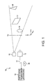
FIG. 1 is a drawing illustrating an example of a depth data generating system;
FIG. 2 is a drawing illustrating an example of a spatial light pattern;
FIG. 3 is a drawing illustrating an example of the blurring of a spatial light pattern that monotonously increases in the depth direction on an object surface;
FIG. 4 is a block diagram illustrating an example of the configuration of a depth data generating apparatus;
FIG. 5 is a flowchart illustrating a method for generating depth data performed by the depth data generating apparatus;
FIG. 6 is a block diagram illustrating an example of the configuration of a reflectance correcting unit;
FIG. 7 is a flowchart illustrating the process of performing luminance correction performed by the reflectance correcting unit;
FIG. 8 is a block diagram illustrating an example of the configuration of a depth map generating unit;
FIG. 9 is a flowchart illustrating a method for determining depth data performed by the depth map generating unit; and
FIG. 10 is a drawing illustrating an example of a monotonous blurring increase in the depth direction; all arranged in accordance with at least some embodiments described herein.
DETAILED DESCRIPTION
The following detailed description sets forth various examples along with specific details to provide a thorough understanding of claimed subject matter. It will be understood by those skilled in the art, however, that claimed subject matter may be practiced without some or more of the specific details disclosed herein. Further, in some circumstances, well-known methods, procedures, systems, components and/or circuits have not been described in detail in order to avoid unnecessarily obscuring claimed subject matter. In the following detailed description, reference is made to the accompanying drawings, which form a part hereof. In the drawings, similar symbols typically identify similar components, unless context dictates otherwise. The illustrative embodiments described in the detailed description, drawings, and claims are not meant to be limiting. Other embodiments may be utilized, and other changes may be made, without departing from the spirit or scope of the subject matter presented here. It will be readily understood that the aspects of the present disclosure, as generally described herein, and illustrated in the Figures, can be arranged, substituted, combined, separated, and designed in a wide variety of different configurations, all of which are explicitly contemplated herein.
This disclosure is drawn, inter alia, to methods, apparatus, devices, and/or systems related to the generation of depth data.
Briefly stated, technologies are generally described herein for a method of and apparatus for generating depth data. In some examples, the method may include obtaining an image of one or more objects on which a spatial light pattern is projected, wherein blurring of the spatial light pattern in the image monotonously increases or decreases in a depth direction, calculating a value of a spatial frequency component of the image in a local image area around a pixel of interest, and determining depth data corresponding to the calculated value of the spatial frequency component by utilizing a preset relationship between depths and values of the spatial frequency component.
FIG. 1 is a drawing illustrating an example of a depth data generating system arranged in accordance with at least some embodiments described herein. A depth data generating system 10 illustrated in FIG. 1 may include a projection unit 11, an imaging unit 12, and a depth data generating apparatus 13. For the sake of convenience of explanation, three orthogonal directions in space may be represented by the x, y, and z axes of a coordinate system, with the z axis corresponding to the depth direction of the projection unit 11 and the imaging unit 12. The projection unit 11 may be configured to emit a spatial light pattern. The projection unit 11 may be a conventional projector capable of projecting a high-definition image generated by a film medium or the like. The projection unit 11 may alternatively be a digital projector employing liquid-crystal-display panels or a DLP (digital light processing) projector employing Digital Micro-Mirror Devices. In such a case, display data of the spatial light pattern to be projected may be input into the projection unit 11. The imaging unit 12 may be configured to capture an image of one or more objects 16 through 18 on which the spatial light pattern is projected. The imaging unit 12 may be a camera that employs an imaging device such as a CCD (Charge Coupled Device) image sensor or CMOS (Complementary Metal Oxide Semiconductor) image sensor. The optical system parameters of the projection unit 11 and the imaging unit 12 may be adjusted such that blurring of the spatial light pattern in the captured image monotonously increases or decreases in the depth direction z. How to achieve such optical system parameters may be described later in detail.
The imaging unit 12 may operate as a still camera to produce a single image at a time, or may operate as a video or motion camera to produce a series of images continuously during an activated state. Images produced or generated by the imaging unit 12 are supplied to the depth data generating apparatus 13. The supply of the images may be via a transitory medium 14 or a non-transitory medium 15. The transitory medium 14 may be a communication line through which electrical signals are transmitted, or may be space through which electromagnetic signals are transmitted. The non-transitory medium 15 may be a tangible recording medium such as a Compact Disc (CD), a Digital Versatile Disk (DVD), a memory card, or the like.
The depth data generating apparatus 13 may be configured to generate depth data indicative of a position z in the depth direction at a pixel corresponding to any given x, y position in an image captured by the imaging unit 12. Such depth data may be extracted from an image captured by the imaging unit 12. Namely, the depth data generating apparatus 13 may generate depth data indicative of the distance of the object 16, for example, from the imaging unit 12 by analyzing the image captured by the imaging unit 12. The depth data generating apparatus 13 may generate a depth map indicative of depths at all the pixels in the image.
In order to generate depth data, the depth data generating apparatus 13 may calculate a value of a pre-determined spatial frequency component of the image in a local image area around a pixel of interest. The depth data generating apparatus 13 may then determine depth data corresponding to the calculated value of the spatial frequency component by utilizing a preset relationship between depths and values of the spatial frequency component. As previously noted, the blurring of the spatial light pattern in the captured image may monotonously increase or decrease in the depth direction z. In such a case, the value of the predetermined spatial frequency component may monotonously increase or decrease in the depth direction z. The relationship between depths and values of the predetermined spatial frequency component may be provided as a mathematical formula. Alternatively, the relationship between depths and values of the predetermined spatial frequency component may be obtained in advance and stored as a lookup table or the like in memory. This lookup table may be referred to when determining depth data, so that a depth value corresponding to the value of the predetermined spatial frequency component calculated for a pixel of interest may be located in the table.
FIG. 2 is a drawing illustrating an example of the spatial light pattern arranged in accordance with at least some embodiments described herein. In this example, the spatial light pattern may be a checkerboard pattern in which black square areas and white square areas are arranged alternately both in the vertical direction and in the horizontal direction. The projection unit 11 and the imaging unit 12 may be configured to have substantially the same angle of view. In such a case, each square area of the spatial light pattern projected by the projection unit 11 on a surface may appear to have a constant two-dimensional size in an image taken by the imaging unit 12 regardless of the distance z of the surface from the projection unit 11. That is, in the example illustrated in FIG. 1, the spatial light pattern projected on the surface of the object 16 may appear to have the same size as the spatial light pattern projected on the surface of the object 17 or 18 when viewed by the imaging unit 12. The projection unit 11 may be configured to have a focus position at a point zpf in the depth direction such that the focus point zpf is nearer than any objects (e.g., 16, 17, 18) that may be captured by the imaging unit 12. This arrangement may ensure that the blurring of the spatial light pattern monotonously increases in the depth direction z on an object surface situated at depth z. The projection unit 11 may have a focus position that is farther away from the projection unit 11 than any objects. This arrangement may ensure that the blurring of the spatial light pattern monotonously decreases in the depth direction z on an object surface situated at depth z.
FIG. 3 is a drawing illustrating an example of the blurring of a spatial light pattern that monotonously increases in the depth direction z on an object surface arranged in accordance with at least some embodiments described herein. In FIG. 3, an image 30 captured by the imaging unit 12 may include an image 31 of the object 16 (see FIG. 1), an image 32 of the object 17, and an image 33 of the object 18. As illustrated in FIG. 1, the object 16, the object 17, and the object 18 may be arranged in the depicted order in the depth direction z, with the object 16 being the nearest to the imaging unit 12. In such a case, a spatial light pattern 34 projected on the nearest object 16 may be the sharpest, and a spatial light pattern 36 projected on the farthest object 18 may be the most blurred, with a spatial light pattern 35 projected on the object 17 being in the middle in terms of sharpness. Depth data may be extracted from the image 30 by analyzing, in a local image area of interest, the value of the predetermined frequency component which may be a function of the degree of blurring of the spatial light patterns 34, 35, and 36 appearing in the image 30.
The spatial light pattern projected by the projection unit 11 may be configured such that the spatial light patterns 34, 35, and 36 appearing in the captured image 30 are so fine that a person looking at the image 30 may not recognize the existence of the spatial light patterns. Such a fine light pattern may be produced by a digital projector which employs a liquid-crystal-display panel having a large number of pixels such as 1280.times.1024 pixels, 1920.times.1080 pixels, or the like. Under normal viewing conditions, human view may not perceive details as small as the size of a few pixels. That is, the spatial light patterns appearing in the image may be periodic at spatial frequency that is higher than spatial frequencies perceivable to human vision when the image is viewed. This arrangement may ensure that the quality of the image 30 from an aesthetic point of view be not undermined by the superimposed spatial light patterns. It may be noted, however, that the size of each square area of the checkerboard pattern may be at least twice as large as the pixel size both in the x direction and in the y direction. This arrangement may ensure that a proper sampling pitch be achieved by the imaging unit 12 in order to extract accurate information about the frequency components of the spatial light pattern.
The description provided above in respect of the spatial light pattern appearing in the image 30 of FIG. 3 has not taken into account the focusing of the imaging unit 12. If the imaging unit 12 is a pinhole camera, for example, the imaging unit 12 may be able to focus on any object at any distance. In such a case, a spatial light pattern projected on a given object surface may appear blurred in the captured image as it is on the object surface. That is, the focusing of the imaging unit 12 may be disregarded under some circumstances.
In reality, however, the characteristics of the optical system of the imaging unit 12 may affect the blurring of the spatial light pattern that appears in a captured image. That is, the focusing of the imaging unit 12 in addition to the focusing of the projection unit 11 may need to be taken into account when generating depth data from the image captured by the imaging unit 12. In some circumstances, the imaging unit 12 may focus on the object 16 that is an object of interest. In other circumstances, the imaging unit 12 may focus on the object 17 that is an object of interest, and may then focus on the object 18 that is a next object of interest. How to take into account the focusing of the imaging unit 12 and changes in its focus position are further described below. It may be noted here, however, that despite the focusing of the imaging unit 12, provision may easily be made such that the blurring of the spatial light pattern in the captured image monotonously increases or decreases in the depth direction z. Such monotonous characteristics may be provided by ensuring that a monotonous blurring increase (or decrease) in the depth direction caused by the projection unit 11 be predominant over a blurring change in the depth direction caused by the imaging unit 12.
FIG. 4 is a block diagram illustrating an example of the configuration of the depth data generating apparatus 13 arranged in accordance with at least some embodiments described herein. The depth data generating apparatus 13 illustrated in FIG. 4 may include an image receiving unit 41, a frequency component calculating unit 42, a reflectance correcting unit 43, a depth map generating unit 44, and a frequency detecting unit 45.
FIG. 5 is a flowchart illustrating a method for generating depth data performed by the depth data generating apparatus 13 arranged in accordance with at least some embodiments described herein. As depicted, an example method may include one or more operations, actions, or functions as illustrated by one or more of blocks S1, S2, S3, S4, S5 and/or S6. As the method in FIG. 5 could be implemented using, for example, the depth data generating apparatus 13 depicted in FIG. 4, the method for generating depth data will be described by referring to FIG. 4 and FIG. 5.
The image receiving unit 41 may receive from the imaging unit 12 an image of one or more objects on which a spatial light pattern is projected. In this image, the blurring of the spatial light pattern may monotonously increase or decrease in the depth direction. Processing may begin at block S1. At block S1, the frequency detecting unit 45 may divide the image into blocks, each of which may be a rectangular image area comprised of an array of pixels. Processing may continue from block S1 to block S2.
At block S2, the frequency detecting unit 45 may apply orthogonal transformation, such as a Fourier transform or a Hadamard transform, to each block to obtain frequency component F(u,v) for each block. Here, F(u,v) may be a discrete Fourier transform (or Hadamard transform, or any other orthogonal transform) of pixel data b(x,y), which represents the pixel values of the pixel array corresponding to a block of interest. Coordinates x and y may represent pixel positions within the block of interest. Variable u represents spatial frequency in the x direction, and variable v represents spatial frequency in the y direction. Processing may continue from block S2 to block S3.
At block S3, the frequency detecting unit 45 may add up F(u,v) of all the blocks to obtain S(u,v), and may find the largest value of S(u,v) in a frequency range above a threshold frequency. S(u,v) may be the sum of F(u,v) of the first block, F(u,v) of the second block, F(u,v) of the third block, . . . , and F(u,v) of the N-th block when there are N blocks in the image. Since the spatial light pattern periodic at certain spatial frequency is included in the image, S(u,v) may have a local maximum value at this spatial frequency within a frequency range above a certain threshold frequency. This threshold frequency may be determined by taking into account the spatial frequency at which the spatial light pattern is periodic. For example, the threshold frequency may be set lower than the above-noted special frequency but higher than most of the frequency spectrum of image information attributable to the captured scene. Since most of the frequency spectrum of image information attributable to the captured scene (i.e., excluding image information attributable to the projected spatial light pattern) resides at lower frequencies, the provision of such a threshold frequency may make it possible to detect the local maximum of the spectrum attributable to the projected spatial light pattern. In this manner, spatial frequency (um,vm) at which the spatial light pattern is periodic may be detected. Processing may continue from block S3 to block S4.
At block S4, the frequency component calculating unit 42 may apply orthogonal transformation, such as the Fourier transform or the Hadamard transform, to a local image area around each pixel of interest at coordinates (x,y) to obtain frequency component Fx,y(um,vm). This local image area may be a rectangular image area centered at coordinates (x,y). Here, Fx,y(u,v) may be a discrete Fourier transform (or Hadamard transform, or any other orthogonal transform) of pixel data, which are the pixel values of the pixel array of the local image area. Processing may continue from block S4 to block S5.
At block S5, the reflectance correcting unit 43 may correct Fx,y(um,vm) for different object reflectance. The spatial light pattern projected by the projection unit 11 may be reflected by an object surface to reach the imaging unit 12. The intensity of the reflected light may depend on the reflectance of the object surface. As a result, pixel values (i.e., luminance values) of the captured image are dependent on the reflectance of each object surface. As the reflectance of the object surface increases, the pixel value of a pixel situated within an image area corresponding to this object surface may also increase. It follows that the value of Fx,y(um,vm) may also depend on object surface reflectance. The reflectance correcting unit 43 may remove variation in Fx,y(um,vm) caused by differences in object surface reflectance. This correction process may be described later in detail. Processing may continue from block S5 to block S6.
At block S6, the depth map generating unit 44 may generate a depth map based on the corrected Fx,y(um,vm) and a lookup table. The lookup table may indicate a relationship between depths (i.e., positions in the z direction) and the values of the spatial frequency component Fx,y(um,vm). This lookup table may be prepared in advance and stored in memory.
FIG. 6 is a block diagram illustrating an example of the configuration of the reflectance correcting unit 43 arranged in accordance with at least some embodiments described herein. The reflectance correcting unit 43 illustrated in FIG. 6 may include a global average luminance calculating unit 61, a correcting unit 62, and a local average luminance calculating unit 63.
FIG. 7 is a flowchart illustrating a method for performing luminance correction performed by the reflectance correcting unit 43 arranged in accordance with at least some embodiments described herein. As depicted, an example method may include one or more operations, actions, or functions as illustrated by one or more of blocks S21, S22 and/or S23. As the method in FIG. 7 could be implemented using, for example, the reflectance correcting unit 43 depicted in FIG. 6, the method for performing luminance correction will be described by referring to FIG. 6 and FIG. 7. Processing may begin at block S21.
At block S21, the global average luminance calculating unit 61 may calculate average luminance DCA of the entire image. The average luminance DCA of the entire image may be calculated by adding up all the pixel values and by dividing the obtained sum by the number of pixels. Alternatively, the average luminance DCA of the entire image may be calculated by using a direct current component Fx,y(0,0) that may be obtained together with Fx,y(um,vm). Since the direct current component Fx,y(0,0) is proportional to the sum of pixel values within the local image area, the global average luminance calculating unit 61 may use Fx,y(0,0) to obtain the average luminance DCA of the entire image. Processing may continue from block S21 to block S22.
At block S22, the local average luminance calculating unit 63 may calculate average luminance DCxy of a local image area around each pixel of interest situated at coordinates (x,y). The average luminance DCxy of the local image area may be calculated by adding up all the pixel values of the local image area and by dividing the obtained sum by the number of pixels. Alternatively, the average luminance DCxy of the local image area may be directly obtained from the direct current component Fx,y(0,0). Processing may continue from block S22 to block S23.
At block S23, the correcting unit 62 may multiply Fx,y(um,vm) by DCA/DCxy for luminance correction. It may be noted that local average luminance DCxy of a local image area may be proportional to the reflectance of an object surface corresponding to this local image area. Further, the value of Fx,y(um,vm) may also be proportional to the reflectance of the object surface corresponding to this local image area. Accordingly, multiplication by DCA/DCxy may remove the effect of object-surface reflectance variation from Fx,y(um,vm). It may also be noted that for the purpose of removing the effect of object-surface reflectance variation, it may suffice to multiply Fx,y(um,vm) by 1/DCxy.
FIG. 8 is a block diagram illustrating an example of the configuration of the depth map generating unit 44 arranged in accordance with at least some embodiments described herein. The depth map generating unit 44 illustrated in FIG. 8 includes a camera parameter obtaining unit 81, an A(z) calculating unit 82, an LUT generating unit 83, a depth calculating unit 84, and an LUT (lookup table) 85 indicative of B(z). A(z) may represent a relationship between position in the depth direction and the blurring of the spatial light pattern caused by the projection unit 11 that projects the spatial light pattern. B(z) may represent a relationship between position in the depth direction and the blurring of the spatial light pattern caused by the imaging unit 12 that captures an image.
FIG. 9 is a flowchart illustrating a method for determining depth data performed by the depth map generating unit 44 arranged in accordance with at least some embodiments described herein. As depicted, an example method may include one or more operations, actions, or functions as illustrated by one or more of blocks S31, S32, S33, S34 and/or S35. The depicted example method determines depth data by combining the effect of focusing of the projection unit 11 with the effect of focusing of the imaging unit 12. As the method in FIG. 9 could be implemented using, for example, the depth map generating unit 44 depicted in FIG. 8, the method for determining depth data will be described by referring to FIG. 8 and FIG. 9. Processing may begin at block S31.
At block S31, the camera parameter obtaining unit 81 may obtain a focus position za, in the z direction and an aperture size D from the imaging unit 12. The camera parameter obtaining unit 81 may also obtain a focus position (xcf,ycf), at which point in the x-y plane the imaging unit 12 focuses on an object surface. The aperture size D may typically be provided in the form of a focal length f and an f-number N. The aperture size (i.e., the diameter of an entrance pupil) D may then be calculated as D=f/N. Processing may continue from block S31 to block S32.
At block S32, the A(z) calculating unit 82 may calculate a depth-dependent amplitude variation A(z) of the spatial pattern frequency caused by the camera optical system (i.e., the imaging unit 12) as a function of depth z based on the focus position zcf and the aperture size D. This depth-dependent amplitude variation A(z) may represent the amplitude of the spatial frequency (um,vm) of the spatial light pattern on a surface positioned at depth z as viewed by the imaging unit 12 focusing on the focus position zcf. This spatial light pattern may be an ideal spatial light pattern having no blurring on the surface positioned at depth z. Namely, the depth-dependent amplitude variation A(z) may take into account only the blurring of the spatial light pattern caused by the imaging unit 12 under the condition in which the blurring of the spatial light pattern caused by the projection unit 11 is nonexistent.
The depth-dependent amplitude variation A(z) may be obtained as follows. A point-spread function of the imaging unit 12 focusing on the distance zcf may be represented as psf(x,y,z) that assumes a value of (2(zcf+z)/Dz)2/pi (pi=3.14 . . . ) within a circular area having a diameter of Dz/(zcf+z) and that assumes zero outside this circular area. The spatial light pattern positioned at depth z may then appear in an image captured by the imaging unit 12 as p(x,y)=p0(x,y)*psf(x,y,z) where p0(x,y) is the spatial light pattern at position zcf and the symbol “*” represents a convolution operation. An orthogonal transform (e.g., Fourier transform or Hadamard transform) of p(x,y) with respect to x and y may be represented as P(u,v)=P0(u,v)PSF(u,v,z) where P0(u,v) and PSF(u,v,z) are orthogonal transforms of p0(x,y) and psf(x,y,z), respectively. Then, the depth-dependent amplitude variation A(z) may be equal to P(um,vm) where (um,vm) is the spatial frequency at which the spatial light pattern is periodic. Processing may continue from block S32 to block S33.
At block S33, the LUT generating unit 83 may create a lookup table Bc(z) indicative of a relationship between Fx,y(um,vm) and depth z based on A(z) and B(z) where B(z) represents the blurring of the spatial light pattern caused by the projection unit 11. B(z) may be obtained in advance as follows. First, the projection unit 11 may project the spatial light pattern (e.g., checkerboard pattern) on a blank, flat surface (e.g., white, flat surface) positioned at depth z while focusing on the depth zpf as described in connection with FIG. 1. An image of this spatial light pattern on the surface positioned at depth z may then be captured by the imaging unit 12 focusing on this surface positioned at depth z. A spatial light pattern p(x,y,z) in the captured image may include blurring caused by the projection unit 11, but may not include blurring caused by the imaging unit 12. When an orthogonal transform of p(x,y,z) with respect to x and y is denoted as P(u,v,z), B(z) may be represented as P(um,vm,z). B(z) obtained in this manner in advance may be stored as a lookup table B(z) in memory. The depth-dependent amplitude variation that factors in both the blurring caused by the projection unit 11 and the blurring caused by the imaging unit 12 may then be represented as A(z)B(z). Namely, A(z)B(z) may be stored as a lookup table Bc(z). It may be noted that B(z) may alternatively be obtained as the depth-dependent characteristics of a point-spread function by projecting a single light spot rather than the spatial light pattern such as a checkerboard pattern. It may further be noted that B(z) may alternatively be obtained as a mathematical formula that approximates a point-spread function of the projection unit 11. The point spread function may be similar to psf(x,y,z) previously described, or may be represented by a Gaussian function. When B(z) is provided as a mathematical formula, Bc(z) may also be obtained as a mathematical formula rather than as a lookup table. Processing may continue from block S33 to block S34.
At block S34, the depth calculating unit 84 may standardize Fx,y(um,vm) for a luminance factor. As previously described, the value of the frequency component as corrected by the reflectance correcting unit 43 for reflectance variation may be Fx,y(um,vm) DCA/DCxy. The focus position (xcf,ycf) at which point in the x-y plane the imaging unit 12 focuses on an object surface may be obtained from the imaging unit 12 in block S1 of FIG. 9. The value of Fx,y(um,vm) DCA/DC, at this focus position (xcf,ycf) may be denoted as Rxy. Then, the depth calculating unit 84 may standardize the value of Fx,y(um,vm) DCA/DCxy at any given spatial coordinates (x,y) in the captured image by multiplying this value by Bc(zcf)/Rxy . This standardization process may ensure that the amplitude of the spatial frequency (um,vm) at the focus position (xcf,ycf) at the focus depth zcf be equal to Bc(zcf). Processing may continue from block S34 to block S35.
At block S35, the depth calculating unit 84 may determine a depth at each pixel position based on the standardized. Namely, the depth calculating unit 84 may refer to the lookup table Bc(z) to find a depth z associated with the (Fx,y(um,vm) DCA/DCxy)x(Bc(zcf)/Rxy). The depth z found in the lookup table Bc(z) may be the depth at which an object surface corresponding to the pixel position (x,y) is positioned in the scene captured by the imaging unit 12.
In the manner described above, the blurring of the spatial light pattern caused by the projection unit 11 and the blurring of the spatial light pattern caused by the imaging unit 12 may both be taken into account in a depth map generated by the depth map generating unit 44. Further, as previously noted, despite the focusing of the imaging unit 12, provision may easily be made such that the blurring of the spatial light pattern in the captured image monotonously increases or decreases in the depth direction z. Such monotonous characteristics may be provided by ensuring that a monotonous blurring increase (or decrease) in the depth direction caused by the projection unit 11 be predominant over a blurring change in the depth direction caused by the imaging unit 12.
FIG. 10 is a drawing illustrating an example of a monotonous blurring increase in the depth direction arranged in accordance with at least some embodiments described herein. The horizontal axis may represent depth z, and the vertical axis may represent the amplitude of the spatial frequency (um,vm). A characteristic curve 91 may correspond to A(z), which may represent the blurring of the spatial light pattern caused by the imaging unit 12. The imaging unit 12 may have a focus position at an object of interest, so that the characteristics curve 91 may have a maximum peak at this focus position in the depth direction z. A characteristic curve 92 may correspond to B(z), which may represent the blurring of the spatial light pattern caused by the projection unit 11. The projection unit 11 may have a focus position at the nearest point in the depth direction z, so that the characteristics curve 92 monotonously falls as depth z increases. Namely, the blurring represented by the characteristic curve 92 may monotonously increase as depth z increases.
As illustrated in FIG. 10, provision may be made such that a monotonous blurring increase in the depth direction caused by the projection unit 11 be predominant over a blurring change in the depth direction caused by the imaging unit 12. Accordingly, a characteristics curve 93 which corresponds to Bc(z)=A(z)B(z) may monotonously fall as depth z increases. That is, blurring obtained by combining the blurring caused by the projection unit 11 and the blurring caused by the imaging unit 12 may monotonously increase as depth z increases. With such blurring characteristics, depth data may be uniquely determined from a given amplitude of the spatial frequency (um,vm).
References made in this disclosure to the term “responsive to” or “in response to” are not limited to responsiveness to only a particular feature and/or structure. A feature may also be responsive to another feature and/or structure and also be located within that feature and/or structure. Moreover, when terms or phrases such as “coupled” or “responsive” or “in response to” or “in communication with”, etc. are used herein or in the claims that follow, these terms should be interpreted broadly. For example, the phrase “coupled to” may refer to being communicatively, electrically and/or operatively coupled as appropriate for the context in which the phrase is used.
Some portions of the foregoing detailed description are presented in terms of algorithms or symbolic representations of operations on data bits or binary digital signals stored within a computing system memory, such as a computer memory. These algorithmic descriptions or representations are examples of techniques used by those of ordinary skill in the data processing arts to convey the substance of their work to others skilled in the art. An algorithm is here, and generally, is considered to be a self-consistent sequence of operations or similar processing leading to a desired result. In this context, operations or processing involve physical manipulation of physical quantities. Typically, although not necessarily, such quantities may take the form of electrical or magnetic signals capable of being stored, transferred, combined, compared or otherwise manipulated. It has proven convenient at times, principally for reasons of common usage, to refer to such signals as bits, data, values, elements, symbols, characters, terms, numbers, numerals or the like. It should be understood, however, that all of these and similar terms are to be associated with appropriate physical quantities and are merely convenient labels. Unless specifically stated otherwise, as apparent from the following discussion, it is appreciated that throughout this specification discussions utilizing terms such as “processing,” “computing,” “calculating,” “determining” or the like refer to actions or processes of a computing device, that manipulates or transforms data represented as physical electronic or magnetic quantities within memories, registers, or other information storage devices, transmission devices, or display devices of the computing device.
The foregoing detailed description has set forth various embodiments of the devices and/or processes via the use of block diagrams, flowcharts, and/or examples. Insofar as such block diagrams, flowcharts, and/or examples contain one or more functions and/or operations, it will be understood by those within the art that each function and/or operation within such block diagrams, flowcharts, or examples can be implemented, individually and/or collectively, by a wide range of hardware, software, firmware, or virtually any combination thereof. In one embodiment, several portions of the subject matter described herein may be implemented via Application Specific Integrated Circuits (ASICs), Field Programmable Gate Arrays (FPGAs), digital signal processors (DSPs), or other integrated formats. However, those skilled in the art will recognize that some aspects of the embodiments disclosed herein, in whole or in part, can be equivalently implemented in integrated circuits, as one or more computer programs running on one or more computers (e.g., as one or more programs running on one or more computer systems), as one or more programs running on one or more processors (e.g., as one or more programs running on one or more microprocessors), as firmware, or as virtually any combination thereof, and that designing the circuitry and/or writing the code for the software and/or firmware would be well within the skill of one of skill in the art in light of this disclosure. In addition, those skilled in the art will appreciate that the mechanisms of the subject matter described herein are capable of being distributed as a program product in a variety of forms, and that an illustrative embodiment of the subject matter described herein applies regardless of the particular type of signal bearing medium used to actually carry out the distribution. Examples of a signal bearing medium include, but are not limited to, the following: a recordable type medium such as a flexible disk, a hard disk drive (HDD), a Compact Disc (CD), a Digital Versatile Disk (DVD), a digital tape, a computer memory, etc.; and a transmission type medium such as a digital and/or an analog communication medium (e.g., a fiber optic cable, a waveguide, a wired communication link, a wireless communication link, etc.).
Those skilled in the art will recognize that it is common within the art to describe devices and/or processes in the fashion set forth herein, and thereafter use engineering practices to integrate such described devices and/or processes into data processing systems. That is, at least a portion of the devices and/or processes described herein can be integrated into a data processing system via a reasonable amount of experimentation. Those having skill in the art will recognize that a typical data processing system generally may include one or more of a system unit housing, a video display device, a memory such as volatile and non-volatile memory, processors such as micro-processors and digital signal processors, computational entities such as operating systems, drivers, graphical user interfaces, and applications programs, one or more interaction devices, such as a touch pad or screen, and/or control systems including feedback loops and control motors (e.g., feedback for sensing position and/or velocity; control motors for moving and/or adjusting components and/or quantities). A typical data processing system may be implemented utilizing any suitable commercially available components, such as those typically found in data computing/communication and/or network computing/communication systems.
The herein described subject matter sometimes illustrates different components contained within, or connected with, different other components. It is to be understood that such depicted architectures are merely exemplary, and that in fact many other architectures can be implemented which achieve the same functionality. In a conceptual sense, any arrangement of components to achieve the same functionality is effectively “associated” such that the desired functionality is achieved. Hence, any two components herein combined to achieve a particular functionality can be seen as “associated with” each other such that the desired functionality is achieved, irrespective of architectures or intermedial components. Likewise, any two components so associated can also be viewed as being “operably connected”, or “operably coupled”, to each other to achieve the desired functionality, and any two components capable of being so associated can also be viewed as being “operably couplable”, to each other to achieve the desired functionality. Specific examples of operably couplable include but are not limited to physically mateable and/or physically interacting components and/or wirelessly interactable and/or wirelessly interacting components and/or logically interacting and/or logically interactable components.
With respect to the use of substantially any plural and/or singular terms herein, those having skill in the art can translate from the plural to the singular and/or from the singular to the plural as is appropriate to the context and/or application. The various singular/plural permutations may be expressly set forth herein for sake of clarity.
It will be understood by those within the art that, in general, terms used herein, and especially in the appended claims (e.g., bodies of the appended claims) are generally intended as “open” terms (e.g., the term “including” should be interpreted as “including but not limited to,” the term “having” should be interpreted as “having at least,” the term “includes” should be interpreted as “includes but is not limited to,” etc.). It will be further understood by those within the art that if a specific number of an introduced claim recitation is intended, such an intent will be explicitly recited in the claim, and in the absence of such recitation, no such intent is present. For example, as an aid to understanding, the following appended claims may contain usage of the introductory phrases “at least one” and “one or more” to introduce claim recitations. However, the use of such phrases should not be construed to imply that the introduction of a claim recitation by the indefinite articles “a” or “an” limits any particular claim containing such introduced claim recitation to implementations containing only one such recitation, even when the same claim includes the introductory phrases “one or more” or “at least one” and indefinite articles such as “a” or “an” (e.g., “a” and/or “an” should typically be interpreted to mean “at least one” or “one or more”); the same holds true for the use of definite articles used to introduce claim recitations. In addition, even if a specific number of an introduced claim recitation is explicitly recited, those skilled in the art will recognize that such recitation should typically be interpreted to mean at least the recited number (e.g., the bare recitation of “two recitations,” without other modifiers, typically means at least two recitations, or two or more recitations). Furthermore, in those instances where a convention analogous to “at least one of A, B, and C, etc.” is used, in general, such a construction is intended in the sense one having skill in the art would understand the convention (e.g., “a system having at least one of A, B, and C” would include but not be limited to systems that have A alone, B alone, C alone, A and B together, A and C together, B and C together, and/or A, B, and C together, etc.). In those instances where a convention analogous to “at least one of A, B, or C, etc.” is used, in general, such a construction is intended in the sense one having skill in the art would understand the convention (e.g., “a system having at least one of A, B, or C” would include but not be limited to systems that have A alone, B alone, C alone, A and B together, A and C together, B and C together, and/or A, B, and C together, etc.). It will be further understood by those within the art that virtually any disjunctive word and/or phrase presenting two or more alternative terms, whether in the description, claims, or drawings, should be understood to contemplate the possibilities of including one of the terms, either of the terms, or both terms. For example, the phrase “A or B” will be understood to include the possibilities of “A” or “B” or “A and B.”
It should also be understood that, the term “optimize” may include maximization and/or minimization. The term “minimization” and/or the like as used herein may include a global minimum, a local minimum, an approximate global minimum, and/or an approximate local minimum. Likewise, it should also be understood that, the term “maximization” and/or the like as used herein may include a global maximum, a local maximum, an approximate global maximum, and/or an approximate local maximum.
Reference in the specification to “an implementation,” “one implementation,” “some implementations,” or “other implementations” may mean that a particular feature, structure, or characteristic described in connection with one or more implementations may be included in at least some implementations, but not necessarily in all implementations. The various appearances of “an implementation,” “one implementation,” or “some implementations” in the preceding description are not necessarily all referring to the same implementations.
While certain example techniques have been described and shown herein using various methods and systems, it should be understood by those skilled in the art that various other modifications may be made, and equivalents may be substituted, without departing from claimed subject matter. Additionally, many modifications may be made to adapt a particular situation to the teachings of claimed subject matter without departing from the central concept described herein. Therefore, it is intended that claimed subject matter not be limited to the particular examples disclosed, but that such claimed subject matter also may include all implementations falling within the scope of the appended claims, and equivalents thereof.

Claims (20)

What is claimed is:
1. A method for use at a computing device, the method for transmitting image data for a stereoscopic view of an image, the method comprising:
receiving the image of one or more objects, wherein the image is a two-dimensional image with a superimposed spatial light pattern;
generating depth data associated with the image based on at least a degree of blur of the superimposed spatial light pattern within the image, wherein the blur of the superimposed spatial light pattern within the image increases in a first depth direction of the image and decreases in a second depth direction of the image, and wherein generating the depth data associated with the image comprises:
dividing the image into a plurality of blocks;
for each block included in the plurality of blocks, obtaining a frequency component for the block; and
detecting a local maximum of a spectrum attributable to the superimposed spatial light pattern by adding the frequency components for each block of the plurality of blocks together; and
providing the image together with the depth data to enable the stereoscopic view of the image.
2. The method of claim 1, wherein the superimposed spatial light pattern is projected on the one or more objects during capture of the two-dimensional image.
3. The method of claim 1, wherein the superimposed spatial light pattern is a checkboard pattern.
4. The method of claim 3, wherein the checkboard pattern includes black square areas and white square areas arranged alternately both in a vertical direction and in a horizontal direction.
5. The method of claim 1, wherein generating the depth data associated with the image comprises: accounting for blur of the superimposed spatial light pattern caused by an image projection device and accounting for blur of the superimposed spatial light pattern caused by an image capture device.
6. The method of claim 1, wherein the superimposed spatial light pattern is periodic at a spatial frequency that is higher than spatial frequencies perceivable to human vision.
7. The method of claim 1, wherein obtaining the frequency component for the block comprises obtaining a frequency component that represents pixel values of a pixel array that corresponds to the block.
8. A method for use at a computing device, the method for transmitting image data for a stereoscopic view of an image, the method comprising:
receiving image data that includes a superimposed spatial light pattern, wherein the image data represents a two-dimensional image, and wherein the superimposed spatial light pattern is indicative of depth in the two-dimensional image, based on a degree of blur of the superimposed spatial light pattern within the image data received at an image capture device, and wherein the blur of the superimposed spatial light pattern increases in a first depth direction of the two-dimensional image and decreases in a second depth direction of the two-dimensional image; and
transmitting the image data together with the superimposed spatial light pattern to enable the stereoscopic view of the two-dimensional image, wherein enabling the stereoscopic view of the two-dimensional image includes generating depth data for the two-dimensional image, and wherein generating the depth data comprises:
dividing the two-dimensional image into a plurality of blocks;
obtaining a frequency component for each block of the plurality of blocks; and
detecting a local maximum of a spectrum attributable to the superimposed spatial light pattern by addition of the frequency components for each block of the plurality of blocks together.
9. The method of claim 8, wherein generating the depth data for the two-dimensional image further comprises accounting for blur of the superimposed spatial light pattern caused by an image projection device and accounting for blur of the superimposed spatial light pattern caused by the image capture device.
10. The method of claim 9, wherein the depth data enables the stereoscopic view of the image.
11. The method of claim 9, further comprising:
transmitting image capture parameters of the image capture device, wherein the image capture parameters further enable the generation of the depth data.
12. The method of claim 11, wherein the image capture parameters include at least a focus position and an aperture size of the image capture device.
13. The method of claim 8, wherein transmitting the image data together with the superimposed spatial light pattern to enable the stereoscopic view of the image comprises transmitting the image data together with the superimposed spatial light pattern via one of a transitory medium or a non-transitory medium.
14. The method of claim 13, wherein the transitory medium comprises an electromagnetic signal communication channel.
15. A non-transitory computer-readable medium storing code that, when executed by a processor, causes the processor to:
receive an image of a scene, wherein the image of the scene includes a superimposed spatial light pattern;
generate a depth map of the image based on a degree of blur of the superimposed spatial light pattern within the image of the scene, wherein the blur of the superimposed spatial light pattern within the image of the scene increases in a first depth direction of the image of the scene and decreases in a second depth direction of the image of the scene, and wherein the depth map comprises depth data associated with a plurality of local image areas of the image of the scene, and wherein to generate the depth map of the image, the code, when executed by the processor, causes the processor to;
divide the image of the scene into a plurality of blocks;
for each block included in the plurality of blocks, obtain a frequency component for the block; and
detect a local maximum of a spectrum attributable to the superimposed spatial light pattern by addition of the frequency components for each block of the plurality of blocks together; and
provide the image of the scene and the depth map to enable a stereoscopic view of the image of the scene.
16. The non-transitory computer-readable medium storing code of claim 15, wherein when the code is executed by a processor, further causes the processor to:
calculate a value of a pre-determined spatial frequency component for each of the plurality of local image areas of the image of the scene, wherein each of the plurality of local image areas are associated with a respective pixel of the image of the scene.
17. The non-transitory computer-readable medium storing code of claim 16, wherein when the code is executed by a processor, further causes the processor to:
determine the depth data for each of the plurality of local area images based on the calculated values of the pre-determined spatial frequency component of the image of the scene for each of the plurality of local image areas of the image of the scene.
18. The non-transitory computer-readable medium storing code of claim 17, wherein when the code is executed by a processor, further causes the processor to:
look up a relationship between depth and the calculated values of the predetermined spatial frequency component of the image from a look up table to determine the depth data for each pixel.
19. The non-transitory computer-readable medium storing code of claim 15, wherein the superimposed spatial light pattern includes black square areas and white square areas arranged alternately both in a vertical direction and in a horizontal direction.
20. The non-transitory computer-readable medium storing code of claim 15, wherein the superimposed spatial light pattern is periodic at a spatial frequency that is higher than spatial frequencies perceivable to human vision.
US14/660,769 2010-10-05 2015-03-17 Generation of depth data based on spatial light pattern Expired - Fee Related US9746319B2 (en)

Priority Applications (1)

Application Number Priority Date Filing Date Title
US14/660,769 US9746319B2 (en) 2010-10-05 2015-03-17 Generation of depth data based on spatial light pattern

Applications Claiming Priority (3)

Application Number Priority Date Filing Date Title
PCT/JP2010/005965 WO2012046270A1 (en) 2010-10-05 2010-10-05 Generation of depth data based on spatial light pattern
US201113122912A 2011-04-06 2011-04-06
US14/660,769 US9746319B2 (en) 2010-10-05 2015-03-17 Generation of depth data based on spatial light pattern

Related Parent Applications (2)

Application Number Title Priority Date Filing Date
US13/122,912 Continuation US9030466B2 (en) 2010-10-05 2010-10-05 Generation of depth data based on spatial light pattern
PCT/JP2010/005965 Continuation WO2012046270A1 (en) 2010-10-05 2010-10-05 Generation of depth data based on spatial light pattern

Publications (2)

Publication Number Publication Date
US20150198439A1 US20150198439A1 (en) 2015-07-16
US9746319B2 true US9746319B2 (en) 2017-08-29

Family

ID=45889368

Family Applications (2)

Application Number Title Priority Date Filing Date
US13/122,912 Expired - Fee Related US9030466B2 (en) 2010-10-05 2010-10-05 Generation of depth data based on spatial light pattern
US14/660,769 Expired - Fee Related US9746319B2 (en) 2010-10-05 2015-03-17 Generation of depth data based on spatial light pattern

Family Applications Before (1)

Application Number Title Priority Date Filing Date
US13/122,912 Expired - Fee Related US9030466B2 (en) 2010-10-05 2010-10-05 Generation of depth data based on spatial light pattern

Country Status (6)

Country Link
US (2) US9030466B2 (en)
JP (1) JP5536071B2 (en)
KR (1) KR101494066B1 (en)
CN (1) CN103109158B (en)
BR (1) BR112013008313A2 (en)
WO (1) WO2012046270A1 (en)

Families Citing this family (18)

* Cited by examiner, † Cited by third party
Publication number Priority date Publication date Assignee Title
US9251578B2 (en) 2012-07-02 2016-02-02 Sony Corporation System and method for match move quality control
CN103546736B (en) * 2012-07-12 2016-12-28 三星电子株式会社 Image processing equipment and method
TWI707483B (en) * 2012-07-17 2020-10-11 新加坡商新加坡恒立私人有限公司 Opto-electronic module for emitting light of variable intensity distribution
US9389067B2 (en) * 2012-09-05 2016-07-12 Canon Kabushiki Kaisha Three-dimensional shape measuring apparatus, three-dimensional shape measuring method, program, and storage medium
US10368053B2 (en) 2012-11-14 2019-07-30 Qualcomm Incorporated Structured light active depth sensing systems combining multiple images to compensate for differences in reflectivity and/or absorption
US10257506B2 (en) * 2012-12-28 2019-04-09 Samsung Electronics Co., Ltd. Method of obtaining depth information and display apparatus
US9729860B2 (en) * 2013-05-24 2017-08-08 Microsoft Technology Licensing, Llc Indirect reflection suppression in depth imaging
US9542749B2 (en) * 2014-01-06 2017-01-10 Microsoft Technology Licensing, Llc Fast general multipath correction in time-of-flight imaging
JP2016061622A (en) * 2014-09-17 2016-04-25 株式会社リコー Information processing system and information processing method
CN107209007B (en) * 2014-11-20 2021-07-06 螳螂慧视科技有限公司 Method, device, accessory and system for image acquisition with depth estimation
WO2016117716A1 (en) * 2015-01-20 2016-07-28 재단법인 다차원 스마트 아이티 융합시스템 연구단 Method and apparatus for extracting depth information from image
FR3034078B1 (en) * 2015-03-27 2017-03-24 Airbus Helicopters METHOD AND DEVICE FOR SIGNALING TO THE GROUND AN AIRCRAFT IN FLIGHT AND AN AIRCRAFT PROVIDED WITH SAID DEVICE
WO2016171296A1 (en) * 2015-04-24 2016-10-27 재단법인 다차원 스마트 아이티 융합시스템 연구단 Method and device for estimating depth of image by using aperture of non-square and non-circle shape
WO2017048927A1 (en) * 2015-09-18 2017-03-23 The Regents Of The University Of California Cameras and depth estimation of images acquired in a distorting medium
WO2017079333A1 (en) * 2015-11-04 2017-05-11 Magic Leap, Inc. Light field display metrology
US10234561B2 (en) 2016-05-09 2019-03-19 Microsoft Technology Licensing, Llc Specular reflection removal in time-of-flight camera apparatus
JP6735615B2 (en) * 2016-06-29 2020-08-05 キヤノン株式会社 Information processing apparatus, information processing apparatus control method, and program
US11729370B2 (en) * 2018-11-28 2023-08-15 Texas Instruments Incorporated Multi-perspective display driver

Citations (46)

* Cited by examiner, † Cited by third party
Publication number Priority date Publication date Assignee Title
JPS622118A (en) 1985-06-17 1987-01-08 ヴイユウ エンジニアリング インコ−ポレイテツド Method and device for measuring position in z axial direction
US4920273A (en) 1985-06-17 1990-04-24 View Engineering, Inc. Z-axis measurement system
JPH0560528A (en) 1991-09-03 1993-03-09 Hitachi Ltd Input device for three-dimensional information
JPH10508107A (en) 1995-06-07 1998-08-04 ザ トラスティース オブ コロンビア ユニヴァーシティー イン ザ シティー オブ ニューヨーク Apparatus and method for determining a three-dimensional shape of an object using relative blur in an image due to active illumination and defocus
US6045515A (en) * 1997-04-07 2000-04-04 Lawton; Teri A. Methods and apparatus for diagnosing and remediating reading disorders
JP2001027517A (en) 1999-07-14 2001-01-30 Opton Co Ltd Noncontact shape measuring method
US6330066B1 (en) 1999-05-20 2001-12-11 Sony Corporation Height measuring apparatus and method and testing apparatus using the height measuring apparatus
US20030156260A1 (en) * 2002-01-04 2003-08-21 Neurok Llc Three-dimensional image projection employing retro-reflective screens
US20030156181A1 (en) * 2002-02-19 2003-08-21 Alain Bouchard Technique for printing a color image
US20040036687A1 (en) * 1999-03-01 2004-02-26 Sony Computer Entertainment Inc. Methods and apparatus for rendering an image with depth-of-field display
JP2005017805A (en) 2003-06-27 2005-01-20 Mitsutoyo Corp Focus detecting method of image measuring device, focus detection mechanism, and image measuring device equipped with the focus detection mechanism
US6947582B1 (en) 1999-09-16 2005-09-20 Brainlab Ag Three-dimensional shape detection by means of camera images
US20050254688A1 (en) 2002-01-17 2005-11-17 Matthias Franz Method and device for recognizing obstruction of view in image sensor systems
JP2006098252A (en) 2004-09-30 2006-04-13 Brother Ind Ltd Three-dimensional information acquisition method
US20060098231A1 (en) 2004-11-09 2006-05-11 Sharp Kabushiki Kaisha Image searching device, image forming device, image searching method, image searching program, and computer-readable storage medium
US20070019266A1 (en) * 2005-07-20 2007-01-25 Sony Corporation Holographic stereogram creation device and its method
US20070081200A1 (en) * 2005-03-16 2007-04-12 Columbia University Lensless imaging with controllable apertures
US20070140333A1 (en) 2004-02-20 2007-06-21 Keiichi Chono Image encoding method, device thereof, and control program thereof
WO2008120217A2 (en) 2007-04-02 2008-10-09 Prime Sense Ltd. Depth mapping using projected patterns
US7440590B1 (en) 2002-05-21 2008-10-21 University Of Kentucky Research Foundation System and technique for retrieving depth information about a surface by projecting a composite image of modulated light patterns
US20080308712A1 (en) * 2007-03-22 2008-12-18 Fujifilm Corporation Image capturing apparatus
JP2009008649A (en) 2007-05-31 2009-01-15 Nsk Ltd Wheel-carriage robot
US20090161964A1 (en) * 2007-12-21 2009-06-25 Meir Tzur Detecting Objects In An Image Being Acquired By A Digital Camera Or Other Electronic Image Acquisition Device
US20090187242A1 (en) 2007-08-27 2009-07-23 Advanced Medical Optics, Inc. Intraocular lens having extended depth of focus
US7583272B2 (en) 2004-11-29 2009-09-01 Purdue Research Foundation Methods for retrieving shapes and drawings
US20090234448A1 (en) 2007-08-27 2009-09-17 Advanced Medical Optics, Inc. Intraocular lens having extended depth of focus
US20090238449A1 (en) 2005-11-09 2009-09-24 Geometric Informatics, Inc Method and Apparatus for Absolute-Coordinate Three-Dimensional Surface Imaging
US20090239308A1 (en) * 2008-03-19 2009-09-24 Fluidigm Corporation Method and apparatus for determining copy number variation using digital pcr
US7609724B1 (en) * 2005-04-29 2009-10-27 Qualcomm Incorporated Enhanced frame aggregation in a wireless network system
US20090268985A1 (en) 2008-04-29 2009-10-29 Earl Quong Wong Reduced Hardware Implementation For A Two-Picture Depth Map Algorithm
US20100174599A1 (en) * 2009-01-05 2010-07-08 Apple Inc. System and method for providing content associated with a product or service
US20100238189A1 (en) * 2009-03-19 2010-09-23 Sharp Laboratories Of America, Inc. Area adaptive backlight with reduced computation and halo artifacts
US20100265355A1 (en) * 2009-04-21 2010-10-21 Kenichi Sato Phase correction plate, imaging system and apparatus, mobile phone, in-vehicle device, monitor camera, endoscopic apparatus, digital camera, digital video camera, and lens unit
US20100278390A1 (en) 2003-12-01 2010-11-04 Silveira Paulo E X Task-based imaging systems
US20100296751A1 (en) 2009-05-22 2010-11-25 Canon Kabushiki Kaisha Image processing apparatus, image processing method, and storage medium
US20110020740A1 (en) * 2009-07-23 2011-01-27 Akihiro Sugino Image forming apparatus
US20110019056A1 (en) * 2009-07-26 2011-01-27 Massachusetts Institute Of Technology Bi-Directional Screen
US20110058085A1 (en) * 2009-09-09 2011-03-10 Olympus Imaging Corp. Waterproof camera and display method
US20110080400A1 (en) 2009-10-02 2011-04-07 Victor Company Of Japan, Ltd. Pseudo 3D image creation apparatus and display system
US20110150082A1 (en) 2004-01-30 2011-06-23 Jiuhuai Lu Moving picture coding method and moving picture decoding method
US7999844B2 (en) * 1995-12-22 2011-08-16 Dynamic Digital Depth Research Pty Ltd. Image conversion and encoding techniques
US20110292234A1 (en) * 2010-05-26 2011-12-01 Canon Kabushiki Kaisha Image processing apparatus and image processing method
US20110304532A1 (en) * 2010-05-27 2011-12-15 Samsung Electronics Co., Ltd. Image capturing and display apparatus and method
US20120050501A1 (en) * 2010-08-30 2012-03-01 Tomoya Narita Information Processing Apparatus, Stereoscopic Display Method, and Program
US20120257029A1 (en) 2010-12-17 2012-10-11 Olympus Medical Systems Corp. Endoscope apparatus and method of displaying object image using endoscope
US8885941B2 (en) 2011-09-16 2014-11-11 Adobe Systems Incorporated System and method for estimating spatially varying defocus blur in a digital image

Patent Citations (53)

* Cited by examiner, † Cited by third party
Publication number Priority date Publication date Assignee Title
JPS622118A (en) 1985-06-17 1987-01-08 ヴイユウ エンジニアリング インコ−ポレイテツド Method and device for measuring position in z axial direction
US4743771A (en) 1985-06-17 1988-05-10 View Engineering, Inc. Z-axis height measurement system
US4920273A (en) 1985-06-17 1990-04-24 View Engineering, Inc. Z-axis measurement system
JPH0560528A (en) 1991-09-03 1993-03-09 Hitachi Ltd Input device for three-dimensional information
US5305092A (en) 1991-09-03 1994-04-19 Hitachi, Ltd. Apparatus for obtaining three-dimensional volume data of an object
US6229913B1 (en) 1995-06-07 2001-05-08 The Trustees Of Columbia University In The City Of New York Apparatus and methods for determining the three-dimensional shape of an object using active illumination and relative blurring in two-images due to defocus
JPH10508107A (en) 1995-06-07 1998-08-04 ザ トラスティース オブ コロンビア ユニヴァーシティー イン ザ シティー オブ ニューヨーク Apparatus and method for determining a three-dimensional shape of an object using relative blur in an image due to active illumination and defocus
US7999844B2 (en) * 1995-12-22 2011-08-16 Dynamic Digital Depth Research Pty Ltd. Image conversion and encoding techniques
US6045515A (en) * 1997-04-07 2000-04-04 Lawton; Teri A. Methods and apparatus for diagnosing and remediating reading disorders
US20040036687A1 (en) * 1999-03-01 2004-02-26 Sony Computer Entertainment Inc. Methods and apparatus for rendering an image with depth-of-field display
US6330066B1 (en) 1999-05-20 2001-12-11 Sony Corporation Height measuring apparatus and method and testing apparatus using the height measuring apparatus
JP2001027517A (en) 1999-07-14 2001-01-30 Opton Co Ltd Noncontact shape measuring method
US6947582B1 (en) 1999-09-16 2005-09-20 Brainlab Ag Three-dimensional shape detection by means of camera images
US20030156260A1 (en) * 2002-01-04 2003-08-21 Neurok Llc Three-dimensional image projection employing retro-reflective screens
US20050254688A1 (en) 2002-01-17 2005-11-17 Matthias Franz Method and device for recognizing obstruction of view in image sensor systems
US20030156181A1 (en) * 2002-02-19 2003-08-21 Alain Bouchard Technique for printing a color image
US7440590B1 (en) 2002-05-21 2008-10-21 University Of Kentucky Research Foundation System and technique for retrieving depth information about a surface by projecting a composite image of modulated light patterns
JP2005017805A (en) 2003-06-27 2005-01-20 Mitsutoyo Corp Focus detecting method of image measuring device, focus detection mechanism, and image measuring device equipped with the focus detection mechanism
US7342608B2 (en) 2003-06-27 2008-03-11 Mitutoyo Corporation Focus detecting method, focus detecting mechanism and image measuring device having focus detecting mechanism
US20100278390A1 (en) 2003-12-01 2010-11-04 Silveira Paulo E X Task-based imaging systems
US20110176708A1 (en) 2003-12-01 2011-07-21 Omnivision Technologies, Inc. Task-Based Imaging Systems
US20110150082A1 (en) 2004-01-30 2011-06-23 Jiuhuai Lu Moving picture coding method and moving picture decoding method
US20070140333A1 (en) 2004-02-20 2007-06-21 Keiichi Chono Image encoding method, device thereof, and control program thereof
US20070177160A1 (en) 2004-09-30 2007-08-02 Brother Kogyo Kabushiki Kaisha Three-dimensional object information acquisition using patterned light projection with optimized image-thresholding
JP2006098252A (en) 2004-09-30 2006-04-13 Brother Ind Ltd Three-dimensional information acquisition method
US7602999B2 (en) 2004-11-09 2009-10-13 Sharp Kabushiki Kaisha Image searching device, image forming device, image searching method, image searching program, and computer-readable storage medium
US20060098231A1 (en) 2004-11-09 2006-05-11 Sharp Kabushiki Kaisha Image searching device, image forming device, image searching method, image searching program, and computer-readable storage medium
US7583272B2 (en) 2004-11-29 2009-09-01 Purdue Research Foundation Methods for retrieving shapes and drawings
US20070081200A1 (en) * 2005-03-16 2007-04-12 Columbia University Lensless imaging with controllable apertures
US7609724B1 (en) * 2005-04-29 2009-10-27 Qualcomm Incorporated Enhanced frame aggregation in a wireless network system
US20070019266A1 (en) * 2005-07-20 2007-01-25 Sony Corporation Holographic stereogram creation device and its method
US20090238449A1 (en) 2005-11-09 2009-09-24 Geometric Informatics, Inc Method and Apparatus for Absolute-Coordinate Three-Dimensional Surface Imaging
US20080308712A1 (en) * 2007-03-22 2008-12-18 Fujifilm Corporation Image capturing apparatus
WO2008120217A2 (en) 2007-04-02 2008-10-09 Prime Sense Ltd. Depth mapping using projected patterns
JP2009008649A (en) 2007-05-31 2009-01-15 Nsk Ltd Wheel-carriage robot
US20090234448A1 (en) 2007-08-27 2009-09-17 Advanced Medical Optics, Inc. Intraocular lens having extended depth of focus
US20090187242A1 (en) 2007-08-27 2009-07-23 Advanced Medical Optics, Inc. Intraocular lens having extended depth of focus
US20090161964A1 (en) * 2007-12-21 2009-06-25 Meir Tzur Detecting Objects In An Image Being Acquired By A Digital Camera Or Other Electronic Image Acquisition Device
US20090239308A1 (en) * 2008-03-19 2009-09-24 Fluidigm Corporation Method and apparatus for determining copy number variation using digital pcr
US20090268985A1 (en) 2008-04-29 2009-10-29 Earl Quong Wong Reduced Hardware Implementation For A Two-Picture Depth Map Algorithm
US20100174599A1 (en) * 2009-01-05 2010-07-08 Apple Inc. System and method for providing content associated with a product or service
US20100238189A1 (en) * 2009-03-19 2010-09-23 Sharp Laboratories Of America, Inc. Area adaptive backlight with reduced computation and halo artifacts
US20100265355A1 (en) * 2009-04-21 2010-10-21 Kenichi Sato Phase correction plate, imaging system and apparatus, mobile phone, in-vehicle device, monitor camera, endoscopic apparatus, digital camera, digital video camera, and lens unit
US20100296751A1 (en) 2009-05-22 2010-11-25 Canon Kabushiki Kaisha Image processing apparatus, image processing method, and storage medium
US20110020740A1 (en) * 2009-07-23 2011-01-27 Akihiro Sugino Image forming apparatus
US20110019056A1 (en) * 2009-07-26 2011-01-27 Massachusetts Institute Of Technology Bi-Directional Screen
US20110058085A1 (en) * 2009-09-09 2011-03-10 Olympus Imaging Corp. Waterproof camera and display method
US20110080400A1 (en) 2009-10-02 2011-04-07 Victor Company Of Japan, Ltd. Pseudo 3D image creation apparatus and display system
US20110292234A1 (en) * 2010-05-26 2011-12-01 Canon Kabushiki Kaisha Image processing apparatus and image processing method
US20110304532A1 (en) * 2010-05-27 2011-12-15 Samsung Electronics Co., Ltd. Image capturing and display apparatus and method
US20120050501A1 (en) * 2010-08-30 2012-03-01 Tomoya Narita Information Processing Apparatus, Stereoscopic Display Method, and Program
US20120257029A1 (en) 2010-12-17 2012-10-11 Olympus Medical Systems Corp. Endoscope apparatus and method of displaying object image using endoscope
US8885941B2 (en) 2011-09-16 2014-11-11 Adobe Systems Incorporated System and method for estimating spatially varying defocus blur in a digital image

Non-Patent Citations (3)

* Cited by examiner, † Cited by third party
Title
International Search Report and Written Opinion for PCT Application No. PCT/JP2010/005965, mailed on Dec. 28, 2010.
Kahn, A. et al., "Hiding Depth Map of an Object in its 2D Image: Reversible Watermarking for 3D Cameras", ICCE '09. Digest of Technical Papers International Conference on Consumer Electronics, Jan. 10-14, 2009, 1-2.
Zhang, S, "3D Surface Data Acquisition", Department of Mechanical Engineering, Oct. 16, 2003, 1-32.

Also Published As

Publication number Publication date
US20150198439A1 (en) 2015-07-16
CN103109158B (en) 2015-03-04
KR20130038300A (en) 2013-04-17
KR101494066B1 (en) 2015-02-16
US9030466B2 (en) 2015-05-12
WO2012046270A1 (en) 2012-04-12
JP2013502558A (en) 2013-01-24
JP5536071B2 (en) 2014-07-02
CN103109158A (en) 2013-05-15
US20120081360A1 (en) 2012-04-05
BR112013008313A2 (en) 2020-09-15

Similar Documents

Publication Publication Date Title
US9746319B2 (en) Generation of depth data based on spatial light pattern
US11050994B2 (en) Virtual reality parallax correction
US11315274B2 (en) Depth determination for images captured with a moving camera and representing moving features
US9122946B2 (en) Systems, methods, and media for capturing scene images and depth geometry and generating a compensation image
JP2018522429A (en) Capture and render panoramic virtual reality content
US20110025830A1 (en) Methods, systems, and computer-readable storage media for generating stereoscopic content via depth map creation
US20120140038A1 (en) Zero disparity plane for feedback-based three-dimensional video
KR20180111798A (en) Adaptive stitching of frames in the panorama frame creation process
US20150379720A1 (en) Methods for converting two-dimensional images into three-dimensional images
US9990738B2 (en) Image processing method and apparatus for determining depth within an image
US10567649B2 (en) Parallax viewer system for 3D content
CN112672139A (en) Projection display method, device and computer readable storage medium
Kovács et al. Quality Measurement Of 3D Light-Field Displays
WO2011014421A2 (en) Methods, systems, and computer-readable storage media for generating stereoscopic content via depth map creation
US10341546B2 (en) Image processing apparatus and image processing method
US10529057B2 (en) Image processing apparatus and image processing method
US10438402B2 (en) Image processing apparatus, image processing system, image processing method, and storage medium
CN110870304A (en) Method and apparatus for providing information to a user for viewing multi-view content
WO2021145913A1 (en) Estimating depth based on iris size
US20180124321A1 (en) Image processing apparatus and image processing method
US20190268546A1 (en) Image processing device, image processing method, and program
US10453183B2 (en) Image processing apparatus and image processing method
CN115244570A (en) Merging split pixel data to obtain deeper depth of field
EP3062291A1 (en) An image processing method and apparatus for determining depth within an image
GB2535726A (en) An image processing method and apparatus for determining depth within an image

Legal Events

Date Code Title Description
STCF Information on status: patent grant

Free format text: PATENTED CASE

CC Certificate of correction
AS Assignment

Owner name: CRESTLINE DIRECT FINANCE, L.P., TEXAS

Free format text: SECURITY INTEREST;ASSIGNOR:EMPIRE TECHNOLOGY DEVELOPMENT LLC;REEL/FRAME:048373/0217

Effective date: 20181228

FEPP Fee payment procedure

Free format text: MAINTENANCE FEE REMINDER MAILED (ORIGINAL EVENT CODE: REM.); ENTITY STATUS OF PATENT OWNER: LARGE ENTITY

LAPS Lapse for failure to pay maintenance fees

Free format text: PATENT EXPIRED FOR FAILURE TO PAY MAINTENANCE FEES (ORIGINAL EVENT CODE: EXP.); ENTITY STATUS OF PATENT OWNER: LARGE ENTITY

STCH Information on status: patent discontinuation

Free format text: PATENT EXPIRED DUE TO NONPAYMENT OF MAINTENANCE FEES UNDER 37 CFR 1.362

FP Lapsed due to failure to pay maintenance fee

Effective date: 20210829