US9540072B2 - Snowmobile - Google Patents
Snowmobile Download PDFInfo
- Publication number
- US9540072B2 US9540072B2 US14/812,998 US201514812998A US9540072B2 US 9540072 B2 US9540072 B2 US 9540072B2 US 201514812998 A US201514812998 A US 201514812998A US 9540072 B2 US9540072 B2 US 9540072B2
- Authority
- US
- United States
- Prior art keywords
- snowmobile
- coupled
- toggle link
- carrier roller
- link
- Prior art date
- Legal status (The legal status is an assumption and is not a legal conclusion. Google has not performed a legal analysis and makes no representation as to the accuracy of the status listed.)
- Active
Links
Images


Classifications
-
- B—PERFORMING OPERATIONS; TRANSPORTING
- B62—LAND VEHICLES FOR TRAVELLING OTHERWISE THAN ON RAILS
- B62D—MOTOR VEHICLES; TRAILERS
- B62D55/00—Endless track vehicles
- B62D55/08—Endless track units; Parts thereof
- B62D55/104—Suspension devices for wheels, rollers, bogies or frames
-
- B—PERFORMING OPERATIONS; TRANSPORTING
- B62—LAND VEHICLES FOR TRAVELLING OTHERWISE THAN ON RAILS
- B62M—RIDER PROPULSION OF WHEELED VEHICLES OR SLEDGES; POWERED PROPULSION OF SLEDGES OR SINGLE-TRACK CYCLES; TRANSMISSIONS SPECIALLY ADAPTED FOR SUCH VEHICLES
- B62M27/00—Propulsion devices for sledges or the like
- B62M27/02—Propulsion devices for sledges or the like power driven
-
- B—PERFORMING OPERATIONS; TRANSPORTING
- B60—VEHICLES IN GENERAL
- B60Y—INDEXING SCHEME RELATING TO ASPECTS CROSS-CUTTING VEHICLE TECHNOLOGY
- B60Y2200/00—Type of vehicle
- B60Y2200/20—Off-Road Vehicles
- B60Y2200/252—Snowmobiles
-
- B—PERFORMING OPERATIONS; TRANSPORTING
- B60—VEHICLES IN GENERAL
- B60Y—INDEXING SCHEME RELATING TO ASPECTS CROSS-CUTTING VEHICLE TECHNOLOGY
- B60Y2400/00—Special features of vehicle units
- B60Y2400/86—Suspension systems
-
- B—PERFORMING OPERATIONS; TRANSPORTING
- B62—LAND VEHICLES FOR TRAVELLING OTHERWISE THAN ON RAILS
- B62M—RIDER PROPULSION OF WHEELED VEHICLES OR SLEDGES; POWERED PROPULSION OF SLEDGES OR SINGLE-TRACK CYCLES; TRANSMISSIONS SPECIALLY ADAPTED FOR SUCH VEHICLES
- B62M27/00—Propulsion devices for sledges or the like
- B62M27/02—Propulsion devices for sledges or the like power driven
- B62M2027/023—Snow mobiles characterised by engine mounting arrangements
-
- B—PERFORMING OPERATIONS; TRANSPORTING
- B62—LAND VEHICLES FOR TRAVELLING OTHERWISE THAN ON RAILS
- B62M—RIDER PROPULSION OF WHEELED VEHICLES OR SLEDGES; POWERED PROPULSION OF SLEDGES OR SINGLE-TRACK CYCLES; TRANSMISSIONS SPECIALLY ADAPTED FOR SUCH VEHICLES
- B62M27/00—Propulsion devices for sledges or the like
- B62M27/02—Propulsion devices for sledges or the like power driven
- B62M2027/026—Snow mobiles characterised by the suspension means
-
- B—PERFORMING OPERATIONS; TRANSPORTING
- B62—LAND VEHICLES FOR TRAVELLING OTHERWISE THAN ON RAILS
- B62M—RIDER PROPULSION OF WHEELED VEHICLES OR SLEDGES; POWERED PROPULSION OF SLEDGES OR SINGLE-TRACK CYCLES; TRANSMISSIONS SPECIALLY ADAPTED FOR SUCH VEHICLES
- B62M27/00—Propulsion devices for sledges or the like
- B62M27/02—Propulsion devices for sledges or the like power driven
- B62M2027/028—Snow mobiles characterised by chassis or bodywork
Definitions
- the present application relates to a snowmobile.
- the present invention relates to snowmobiles, and more particularly, the present invention relates generally to a frame assembly and suspension assembly for snowmobiles.
- the present application claims priority to U.S. Provisional Patent Application Ser. No. 61/597,104, filed on Feb. 9, 2012, the subject matter of which is expressly incorporated by reference herein.
- a snowmobile suspension includes two systems, a front suspension system for a pair of skis and a rear suspension system for the track.
- the rear suspension of a snowmobile supports an endless track driven by the snowmobile engine to propel the machine.
- the track is supported beneath a vehicle chassis by a suspension that is designed to provide a comfortable ride and to help absorb the shock of the snowmobile crossing uneven terrain.
- Most modern snowmobiles use a slide rail suspension which incorporates a pair of slide rails along with several idler wheels to support the track in its configuration.
- the slide rails are typically suspended beneath the chassis by a pair of suspension arms, with each arm being attached at its upper end to the chassis of the snowmobile, and at its lower end to the slide rails.
- the mechanical linkage of the slide rails to the suspension arms and to the snowmobile chassis typically is provided by springs and at least one element acting along a linear path, such as a shock absorber, damper, air shock, shock and spring combination, or other linear force element (LFE).
- the springs are loaded to bias the slide rails downwardly away from the snowmobile chassis and the shock absorbers; dampers or LFEs provide damping forces for ride comfort.
- a snowmobile comprises a chassis having a front chassis portion and a rear chassis portion.
- the front chassis portion includes a bulkhead and a steering mount positioned above the bulkhead by way of frame members.
- An engine has at least one intake and at least one exhaust port, and the engine is mounted with the at least one exhaust port facing forwardly.
- a steering post is coupled to the steering mount and extends substantially along a longitudinal centerline of the vehicle and over a top of the engine.
- An exhaust outlet is coupled to the at least one exhaust port, the exhaust outlet projecting vertically upwardly to a position higher than the engine, and projecting rearwardly between the steering post and one of the frame members.
- a snowmobile in another aspect, comprises a chassis having a front chassis portion and a rear chassis portion, the front chassis portion includes a bulkhead.
- An engine is supported by the chassis.
- a steering post extends substantially along a longitudinal centerline of the vehicle and extends over a top of the engine and is coupled to the bulkhead.
- the snowmobile includes front steerable skis; spindles coupled to the skis; steering arms coupled to the spindles; and a first coupling link interconnecting the steering arms and the steering post, the first coupling link being an extruded member forming plural pivot points.
- a snowmobile in another aspect, comprises a chassis extending along a longitudinal axis; and an engine supported by the bulkhead.
- the engine has a crankshaft having a crankshaft axis transverse to the longitudinal axis.
- the engine has a piston coupled to the crankshaft and reciprocates along a piston reciprocation axis, the piston reciprocation axis extending upwardly and forwardly.
- a continuously variable clutch has a drive clutch coupled coaxially to the crankshaft and a driven clutch mounted rearwardly of the drive clutch, wherein a line between a rotational axis of the drive clutch and a rotational axis of the driven clutch define a clutch axis, and wherein an angle formed between the piston reciprocation axis and the clutch axis is approximately 90°.
- a snowmobile comprises a chassis including a bulkhead and a tunnel, an engine supported by the chassis, a front suspension coupled to the bulkhead, a rear suspension coupled to the tunnel, a fuel tank supported by a tunnel top surface, and a frame comprising frame tubes extending downwardly and rearwardly and coupled to rear corners of the tunnel, with the frame tubes flanking the fuel tank.
- a snowmobile comprises a chassis having a bulkhead and a tunnel. An engine is supported by the chassis and a front suspension is coupled to bulkhead. A rear suspension is coupled to the tunnel and slide rails are coupled to the rear suspension. The rear suspension comprises a toggle link pivotally coupled to the tunnel, and a rear control arm coupled between the slide rails and the toggle link. A front control arm is coupled between the slide rails and the tunnel; wherein the snowmobile has a snowmobile center of gravity, and the front control arm is mounted at a position in a range of 300-310 mm relative to the snowmobile center of gravity.
- a snowmobile comprises a chassis, having a bulkhead and a tunnel. An engine is supported by the chassis, and a front suspension is coupled to bulkhead. A rear suspension is coupled to the tunnel. Slide rails are coupled to the rear suspension, where the rear suspension is comprised of a toggle link pivotally coupled to the tunnel, and a rear control arm coupled between the slide rails and the toggle link; a carrier roller coupled to the toggle link, the toggle link being movable to a plurality of positions relative to the toggle link to vary the dynamics of the vehicle propulsion; and a front control arm coupled between the slide rails and the tunnel.
- FIG. 1 shows a front perspective view of a snowmobile according to the present embodiment, shown without the body member and driver's seat;
- FIG. 2 is a front view of the snowmobile of FIG. 1 with the exhaust system removed;
- FIG. 3 is a side view of the snowmobile of FIG. 1 ;
- FIG. 4 is a rear perspective view of the steering system of the present embodiment
- FIG. 5 is a view similar to that of FIG. 4 showing the suspension system removed;
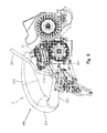
- FIG. 6 is an enlarged view of the steering coupler
- FIG. 7 is a view similar to that of FIG. 2 , including the exhaust system
- FIG. 8 is a top view of the embodiment shown in FIG. 7 ;
- FIG. 9 is a side view of the embodiment in FIG. 8 ;
- FIG. 10 is an enlarged front view of the snowmobile of FIG. 7 ;
- FIG. 11 is a side view of the engine and CVT configuration.
- FIG. 12 shows a rear perspective view of the snowmobile of FIG. 1 ;
- FIG. 13 shows a top view of the snowmobile of FIG. 12 ;
- FIG. 14 shows an enlarged view of the tunnel couplings
- FIG. 15 shows a view similar to that of FIG. 12 less the drive mechanism
- FIG. 16 shows a top view of the snowmobile frame of FIG. 15 ;
- FIG. 17 shows a bottom view of the snowmobile of FIG. 16 ;
- FIG. 18 shows an underside perspective view of the rear suspension
- FIG. 19 shows a rear perspective view of the rear suspension
- FIG. 20 shows a rear perspective view of the snowmobile fuel tank
- FIG. 21 shows a side view of the toggle link
- FIG. 22 shows an alternative embodiment of the toggle link.
- a snowmobile is generally shown at 2 to include a frame 4 , a propulsion system 6 coupled to the frame, an exhaust system 8 coupled to an engine 10 of the propulsion system 6 , a steering system 12 coupled to steerable skis 14 , and front 16 and rear 18 suspensions.
- Frame 4 includes lower cast members 20 , 22 which are fastened together in a clam shell type arrangement.
- Cast members 20 and 22 include integrated upper and lower pivot members 24 , 26 ( FIG. 3 ) and upper pedestals 28 .
- a coupler 30 is provided which couples frame tubes 32 between coupler 30 and pedestal 28 of cast member 20 .
- Cross tube 34 extends between the cast members 20 and 22 .
- Frame tubes 32 could be fastened by any mechanical means such as by fasteners, welding, adhesives and the like.
- frame 4 further includes engine cradle 40 , drive housing 42 , tunnel 44 and brace tubes 46 extending between coupler 30 and cast couplings 50 ( FIG. 1 ) attached to tunnel 44 .
- Suspension 16 includes upper 60 and lower 62 alignment arms having pivot mounts 64 and 66 attachable to pivot members 24 ( FIG. 2 ) and 26 ( FIG. 3 ) where each of the alignment arms 60 , 62 are attached to spindle 68 by way of ball joints 69 ( FIGS. 3 and 4 ) as is known in the art.
- a shock absorber 70 is attached at 72 to lower alignment arm 62 and extends upwardly through upper alignment arm 60 and is attached at 74 to pedestal 28 ( FIGS. 2 and 4 ).
- steering system 12 includes handlebars 80 attached to a steering post 82 which is rotatably fixed at a lower end thereof and rotates relative to a mounting block 84 .
- steering post 82 defines single post, center pivot steering, which extends over the engine 10 as shown best in FIG. 3 .
- steering post 82 includes an outward bend at 83 for clearance of engine 10 .
- Mounting block 84 is attached to a front inner surface of the cast members 20 , 22 by way of fasteners at 86 ( FIGS. 2 and 4 ).
- Steering post 82 includes a pitman arm 87 having a ball joint 88 attached thereto.
- Ball joint 88 is coupled to a ball joint 90 by way of a link 91 .
- Ball joint 90 is attached to a coupling link 92 having four pivot points.
- coupling link 92 is a top extruded member having a pivot cylinder 94 with three radially extending webs or walls 96 , 98 and 100 extending integrally from cylinder 94 , and terminating in respective pivot bosses 102 , 104 and 106 .
- Bosses 102 and 104 are integrally connected by way of an integral link 108 whereas bosses 104 and 106 are interconnected by an integrated link 110 .
- coupling link 92 may be easily attached to the inside of cast member 20 by way of bracket 120 and pivotably mounted relative thereto by way of fastener 122 .
- ball joint 90 is attached to first boss 106 by way of fastener 126 .
- coupling link 92 is interconnected to tie rod 130 at boss 102 by way of fastener 132 .
- tie rod 130 is attached to spindle by way of ball joint 136 ( FIG. 5 ).
- coupling link 92 is interconnected in parallel to a second coupling link 142 by way of a drag link 144 .
- Coupling link 142 is similar to coupling link 92 , however, only includes two radial walls 146 and 150 attached to a pivot cylinder 152 . In a similar manner, coupling link 142 is attached to tie rod 160 by ball joint 162 , which in turn is coupled to spindle 168 by way of ball joint 170 .
- exhaust system 8 includes an exhaust manifold 200 extending forwardly and downwardly from engine 10 , as best shown in FIGS. 8 and 9 .
- Exhaust system 8 includes a first tube portion 202 extending generally longitudinally and forwardly past cast members 20 , 22 and extending under cross tube 34 ( FIGS. 7 and 8 ).
- tube portion 202 extends on the vehicle left hand side of steering post 82 .
- Exhaust system 8 further includes a vertically projecting radiused section 204 which turns the exhaust system 8 vertically upwardly and includes a reversely bent tube section 206 ( FIG.
- Tube portion 206 also extends above cross tube 34 and on the inside of frame tube 32 .
- the exhaust system 8 at the front of the snowmobile 2 is defined between the envelope of frame tubes 32 on either side.
- engine 10 is shown mounted in engine cradle 40 and tipped forward.
- a CVT (continuous variable transmission) drive clutch 210 is mounted coaxially with a crank shaft rotational axis 212 .
- axis 212 is transverse to a longitudinal direction of snowmobile 2 .
- engine 10 is a reciprocating type engine having a piston (not shown) reciprocating within an engine head of engine 10 .
- Engine 10 includes a piston reciprocation axis 214 where axis 214 is rotated forward relative to vertical by an angle ⁇ .
- 11 equals 12°.
- a CVT driven clutch 215 is mounted to drive housing 42 along a rotational axis 216 .
- a CVT belt (not shown) would entrain the drive clutch 210 and the driven clutch 215 to transmit power between the engine 10 and the driven clutch 215 .
- a line drawn between axis 212 and axis 216 is known as the belt center axis, and is shown at 218 .
- As an angle ⁇ is defined between lines 214 and 218 where a is in the range of approximately 70-100°. As shown, a equals 78°. This prevents any reciprocation vibration from being transmitted to the driven clutch 215 .
- Frame tubes 46 include longitudinally extending sections 220 , inwardly directed sections 222 and outwardly directed sections 224 .
- Frame tubes 46 flank fuel tank 230 as described further herein.
- tunnel 44 includes a top wall 240 and side walls 242 defining an internal enclosure for receiving the snowmobile track as is known in the art.
- Couplings 50 are mounted at the rear corners of tunnel 44 at the juncture of the top wall 240 and side walls 242 .
- couplings 50 include apertures 250 receiving frame tube portions 224 , a trunnion portion 252 , and a mounting portion 254 .
- rear suspension 18 will be described in greater detail. It should be appreciated that rear suspension 18 is similar to that described in U.S. patent application Ser. Nos. 11/623,879 and 12/627,642, the subject matter of which are incorporated herein by reference.
- rear suspension 18 includes a front control arm 260 , rear control arm 262 , toggle link 264 and a pair (only one of which is shown) of slide rails 266 .
- front control arm 260 includes upper couplers 270 coupled to an inner surface of tunnel sidewall 242 , arm portions 272 and a coupling tube 274 .
- Coupling tube 274 is interconnected to inside surfaces of slide rail 266 as shown best in FIG. 15 .
- rear control arm 262 includes couplers 280 coupled to slide rail 266 and arms 282 coupled to toggle link 264 .
- Toggle link 264 is generally comprised of arms 290 including front couplers 292 pivotally mounted within trunnion portions 252 of couplers 50 .
- Toggle link 264 further includes rear coupling portions 294 which couple to an upper portion of arms 282 .
- a cross bar 296 locates a shock mount 298 ( FIG. 19 ) as described herein.
- Arms 290 include triangular link portions 300 including couplers 302 for carrying a carrier roller (not shown) which is similar in design to that shown in U.S. patent application Ser. No.
- Brackets 310 may also be provided to hold a rear heat exchanger as shown in U.S. patent application Ser. No. 13/018,824, the subject matter of which is incorporated herein by reference.
- a bracket 320 ( FIG. 19 ) is attached to top surface 240 of tunnel 44 where a shock absorber is mounted between shock mounts 298 and 322 .
- slide rails 266 move upwardly and downwardly relative to tunnel 44 by way of rear suspension 18 . More particularly, as slide rail 266 moves relative to tunnel 44 (or tunnel 44 moves relative to slide rail 266 ), slide rails 266 move by way of front control arms 260 which are interconnected between tunnel 44 and slide rails 266 . Moreover, as slide rails 266 move relative to tunnel 44 , toggle link 264 is moved about couplings 292 towards and away from tunnel 44 under compression from a shock absorber mounted between shock mounts 298 and 322 ( FIG. 19 ).
- Fuel tank 230 is shown in great detail. Fuel tank 230 is shown having a base portion 340 which conforms to the top surface 240 of tunnel 44 , side walls 342 , front wall 344 , and a center narrow portion 346 defining shoulders 348 for receiving frame tubes 46 . Fuel tank 230 further includes a rear opening 350 including a rear wall 352 to receive shock mounting bracket 320 , shoulders 354 for receiving tube portions 224 and a rear opening 356 to receive shock absorber connected to shock mount 322 .
- front ski 14 is attached to spindle 68 at position 400 which extends along a transverse axis 402 .
- the present embodiment differs from the embodiments shown in U.S. patent application Ser. Nos. 11/623,879 and 12/627,642.
- the embodiment differs in that the operator has been positioned closer to the vehicle center of gravity from the previous embodiment, such that the rider is positioned substantially at the vehicle center of gravity, including the fuel and driver (CG f-d ).
- the CG f-d may be changed plus or minus 2 inches based on the rider and the respective position on the snowmobile 2 .
- the front control arm 260 of the rear suspension assembly 18 has been moved rearwardly, which has modified the pitch of the vehicle.
- the tunnel 44 of the present embodiment has been elongated, which has provided several inherent improvements.
- a longitudinal position from ski bolt position 400 to a position of operator's hands on hand grip 404 is shown at X 1 , where X 1 is in a range of 750-770 mm, and in the embodiment shown X 1 equals 29.93 inches (760.24 mm). This is approximately 2.5-4.0 inches forward of the position of the embodiments shown in U.S. patent application Ser. Nos. 11/623,879 and 12/627,642.
- the position of the operator's hands on hand grip 404 is forward of a belt drive axis 406 by a distance of X 2 , where X 2 is in a range of 100-120 mm, and in the embodiment shown X 2 equals 4.385 inches (111.39 mm).
- Snowmobile 2 also includes an operator's foot rest 408 , and a forward most position of foot rest 408 is forward of drive axis 406 by a dimension of X 3 , where X 3 is in a range of 30-50 mm, and in the embodiment shown X 3 equals 1.54 inches (39.1 mm). As also shown in FIG.
- the center of gravity of the vehicle dry with the suspension in the fully extended position is shown at 410 which is rearward of drive axis 406 by a dimension of X 4 , where X 4 is in a range of 65-75 mm, and in the embodiment shown equals 2.699 inches (68.57 mm).
- Position 412 in FIG. 3 represents the pivot axis of front control arm 260 and in particular the position for connection of couplings 270 ( FIG. 17 ) inside the tunnel 44 . This is approximately 5.5 inches rearward of the position shown in the embodiments shown in U.S. patent application Ser. Nos. 11/623,879 and 12/627,642.
- the longitudinal distance for pivot point 412 is positioned a distance of X 5 from drive axis 406 , where X 5 is in a range of 210-260 mm, and in the embodiment shown equals 236.33 mm.
- Position 414 shows a seating position for operator on snowmobile 2 .
- the seating position is rearward of drive axis 406 by a dimension of X 6 , where X 6 is in a range of 405-505 mm, and in the embodiment shown equals 18.00 inches (457.20 mm).
- the positions 404 , 408 and 414 define the operator coordinates relative to the CG d .
- the pivot point 360 for toggle link 264 ( FIG. 15 ) is at the center of coupler 292 .
- the distance between the drive axis 406 and pivot point 360 is X 7 , where X 7 is in a range of 700-800 mm, and in the embodiment shown equals 29.766 inches (756.055 mm). As also shown in FIG.
- a distance from the ski bolt position 400 and spindle pivot axis 402 to the front control arm mounting 412 is in the range of 1000-1200, and is approximately 1100 mm. In the embodiment distance from the ski bolt position 400 to the front control arm mounting 412 is 1107.96 mm (X 1 +X 2 +X 5 ).
- the vertical position of pivot point 412 is Y 1 from a ground position and the vertical position of CG d 410 is in a range of 320-360 mm, and in the embodiment shown is equal to 345.10 mm or an incremental Y 2 , where Y 2 equals 92.22 mm.
- the pivot point 412 of front control arm 260 is rearward of the CG d
- the pivot point of front control arm 260 is forward of the CG d
- the positioning of the front control arm 260 , and particularly the mounting of couplers 270 can vary the amount of the vehicle pitch. The steeper the angle of control arm 260 , the greater the vehicle pitches; whereas the flatter the angle of control arm 260 , the lesser the vehicle pitches. This is due to the vertical force component of front control arm 260 acting on and through the coupler 270 .
- the pivot point for toggle link 264 is at coupler 292 , which is 54.6 mm further back from the position shown in U.S. patent application Ser. Nos. 11/623,879 and 12/627,642. This improves carrier wheel engagement, improves transfer control, reduces sensitivity, increases running-board length, provides room for fuel capacity and provides a more rearward position for the shock mounting.
- toggle link 264 is shown in side view. As mentioned above, toggle link 264 rotates relative to tunnel 44 via pivot couplings 292 and rotates relative to rear control arm 262 by way of pivot coupling 294 . As shown in the FIG. 21 embodiment, legs 300 A, 300 B, which make up link 300 , are substantially the same length. A carrier roller (not shown) is rotatably mounted to coupling 302 . As toggle link 264 is rotatably coupled to tunnel 44 at pivot point 292 , during compression of rear suspension 18 , toggle link 264 rotates counterclockwise. As toggle link 264 rotates, a carrier roller attached at 302 has some slight vertical downward movement before it swings vertically upward. However, the carrier roller may be moved to other positions relative to the toggle link 264 to change the position of the carrier roller, and resultantly, can the dynamic attributes of the snowmobile 2 , as discussed below.
- a carrier roller mounted further rearward along arm 300 B would have immediately upward movement upon counter clockwise rotation of toggle link 264 and would provide more aggressive propulsion of the drive belt. This is due to the increase in bias of the carrier roller, which upon acceleration of snowmobile 2 , causes more load to go down to the rear control arm 262 , then to the slide rail 266 and into the ground. Conversely, if a carrier roller were moved upward to a position 302 ′′ along arm 300 A, upon acceleration, the chassis is pulled down resulting in more vertical lift of the snowmobile during acceleration. It should also be noted that movement rearward, for example to position 302 ′ also increases the cornering ability of the snowmobile 2 .
- a toggle link 324 ′ could be provided having front and rear pivot points 326 and 328 .
- Arms 300 A and 300 B of the FIG. 21 embodiment are replaced by a trapezoidal plate 370 with a roller 372 mounted thereto.
- Roller 372 is mounted about a center of rotation 374 .
- Carrier roller 372 could be positioned within a zone defined within hypothetical box 380 where the desirability of the drive characteristics could be “tuned” by positioned roller on any one of the mounting apertures 382 .
- Hypothetical box 380 is defined relative to a reference line R drawn through the centers of pivot points 326 and 328 , and relative to a tangent line T, tangent to reference line R and through pivot point 326 .
- hypothetical box 340 is approximately positioned between A 1 (80 mm) and A 2 (225 mm) from reference line R, and B 1 (60 mm) and B 2 (225 mm) from reference line T. In the embodiment shown, hypothetical box 340 is positioned between A 1 (80 mm) and A 2 (226.68 mm) from reference line R, and B 1 (59.35 mm) and B 2 (225.23 mm).
Abstract
Description
Claims (21)
Priority Applications (3)
| Application Number | Priority Date | Filing Date | Title |
|---|---|---|---|
| US14/812,998 US9540072B2 (en) | 2012-02-09 | 2015-07-29 | Snowmobile |
| US15/387,544 US11505263B2 (en) | 2012-02-09 | 2016-12-21 | Snowmobile |
| US17/975,082 US20230052282A1 (en) | 2012-02-09 | 2022-10-27 | Snowmobile |
Applications Claiming Priority (3)
| Application Number | Priority Date | Filing Date | Title |
|---|---|---|---|
| US201261597104P | 2012-02-09 | 2012-02-09 | |
| US13/763,282 US9096289B2 (en) | 2012-02-09 | 2013-02-08 | Snowmobile |
| US14/812,998 US9540072B2 (en) | 2012-02-09 | 2015-07-29 | Snowmobile |
Related Parent Applications (1)
| Application Number | Title | Priority Date | Filing Date |
|---|---|---|---|
| US13/763,282 Division US9096289B2 (en) | 2011-08-01 | 2013-02-08 | Snowmobile |
Related Child Applications (1)
| Application Number | Title | Priority Date | Filing Date |
|---|---|---|---|
| US15/387,544 Continuation US11505263B2 (en) | 2012-02-09 | 2016-12-21 | Snowmobile |
Publications (2)
| Publication Number | Publication Date |
|---|---|
| US20150329177A1 US20150329177A1 (en) | 2015-11-19 |
| US9540072B2 true US9540072B2 (en) | 2017-01-10 |
Family
ID=47747842
Family Applications (4)
| Application Number | Title | Priority Date | Filing Date |
|---|---|---|---|
| US13/763,282 Active US9096289B2 (en) | 2011-08-01 | 2013-02-08 | Snowmobile |
| US14/812,998 Active US9540072B2 (en) | 2012-02-09 | 2015-07-29 | Snowmobile |
| US15/387,544 Active US11505263B2 (en) | 2012-02-09 | 2016-12-21 | Snowmobile |
| US17/975,082 Pending US20230052282A1 (en) | 2012-02-09 | 2022-10-27 | Snowmobile |
Family Applications Before (1)
| Application Number | Title | Priority Date | Filing Date |
|---|---|---|---|
| US13/763,282 Active US9096289B2 (en) | 2011-08-01 | 2013-02-08 | Snowmobile |
Family Applications After (2)
| Application Number | Title | Priority Date | Filing Date |
|---|---|---|---|
| US15/387,544 Active US11505263B2 (en) | 2012-02-09 | 2016-12-21 | Snowmobile |
| US17/975,082 Pending US20230052282A1 (en) | 2012-02-09 | 2022-10-27 | Snowmobile |
Country Status (5)
| Country | Link |
|---|---|
| US (4) | US9096289B2 (en) |
| EP (2) | EP2812236B1 (en) |
| CA (3) | CA2863952C (en) |
| RU (1) | RU2014136470A (en) |
| WO (1) | WO2013119958A2 (en) |
Cited By (6)
| Publication number | Priority date | Publication date | Assignee | Title |
|---|---|---|---|---|
| US20170305500A1 (en) * | 2016-04-25 | 2017-10-26 | Arctic Cat Inc. | Spindle and suspension system for recreational vehicles |
| US10493846B2 (en) | 2007-05-16 | 2019-12-03 | Polaris Industries Inc. | All terrain vehicle |
| US10730551B2 (en) | 2016-08-09 | 2020-08-04 | Polaris Industries Inc. | Tracked all-terrain vehicle |
| US10793181B2 (en) | 2018-02-13 | 2020-10-06 | Polaris Industries Inc. | All-terrain vehicle |
| US11286019B2 (en) | 2014-01-10 | 2022-03-29 | Polaris Industries Inc. | Snowmobile |
| US11505263B2 (en) | 2012-02-09 | 2022-11-22 | Polaris Industries Inc. | Snowmobile |
Families Citing this family (13)
| Publication number | Priority date | Publication date | Assignee | Title |
|---|---|---|---|---|
| US8381857B1 (en) | 2006-08-09 | 2013-02-26 | Polaris Industries Inc. | Snowmobile |
| CA2842698C (en) * | 2011-08-01 | 2020-11-17 | Polaris Industries Inc. | Snowmobile |
| US9428028B2 (en) | 2013-05-31 | 2016-08-30 | Skinz Protective Gear | Remotely adjustable degrees of freedom for suspension coupling |
| WO2014194253A1 (en) | 2013-05-31 | 2014-12-04 | Skinz Protective Gear | Remotely adjustable suspension coupling |
| CA2960786A1 (en) * | 2014-09-09 | 2016-03-17 | Bombardier Recreational Products Inc. | Snowmobile fuel tank and frame |
| US20160167722A1 (en) * | 2014-12-11 | 2016-06-16 | Raptor Performance Shocks, LLC | Snow Bike Rear Suspension System |
| WO2016191290A2 (en) | 2015-05-22 | 2016-12-01 | Polaris Industries Inc. | Power boost regulator |
| US10870465B2 (en) * | 2015-05-22 | 2020-12-22 | Polaris Industries Inc. | Power boost regulator |
| JP2017136917A (en) * | 2016-02-02 | 2017-08-10 | ヤマハ発動機株式会社 | Snow mobile |
| CA2995691C (en) | 2017-02-20 | 2020-06-30 | Polaris Industries Inc. | Snowmobile |
| CN109649470B (en) * | 2019-02-01 | 2021-03-05 | 浦江漱金电子科技有限公司 | Sliding propulsion device for ice and snow movement |
| JP2023516273A (en) * | 2020-02-26 | 2023-04-19 | クリアフレーム エンジンズ,インコーポレイテッド | Fuel independent compression ignition engine |
| US11060268B1 (en) | 2020-10-13 | 2021-07-13 | Conivate IP, Inc. | Methods and systems for plumbing fixture installations |
Citations (88)
| Publication number | Priority date | Publication date | Assignee | Title |
|---|---|---|---|---|
| US2834608A (en) * | 1956-07-25 | 1958-05-13 | John B Wixson | Motor vehicle undercarriage protective device |
| USRE26775E (en) | 1968-12-17 | 1970-01-20 | Smieja snow vehicle | |
| US3688856A (en) | 1970-12-14 | 1972-09-05 | Textron Inc | Dual purpose snowmobile hood |
| US3712416A (en) | 1971-11-26 | 1973-01-23 | Donaldson Co Inc | Air intake silencer |
| US3840082A (en) | 1972-11-17 | 1974-10-08 | Brunswick Corp | Drive assembly and suspension for ground-support vehicles |
| US3933213A (en) | 1974-04-11 | 1976-01-20 | Brunswick Corporation | Variable response snowmobile suspension system |
| US3969895A (en) | 1974-06-24 | 1976-07-20 | John Krizman | Power control valve attachment for two cycle motorcycle type engine exhaust systems |
| USRE28922E (en) | 1970-08-17 | 1976-08-03 | Santa Fe International Corporation | Column stabilized stinger |
| US3977493A (en) | 1972-01-27 | 1976-08-31 | Kay Keith Richardson | Exhaust control method and apparatus |
| US4222453A (en) | 1978-11-17 | 1980-09-16 | Arctic Enterprises, Inc. | Rear suspension system for a snowmobile |
| US4339156A (en) * | 1980-08-29 | 1982-07-13 | Caterpillar Tractor Co. | Roller-idler assembly for crawler undercarriage |
| CA1150752A (en) | 1981-07-03 | 1983-07-26 | Jean-Guy Talbot | Slide suspension |
| US4407386A (en) | 1981-12-31 | 1983-10-04 | Yamaha Hatsudoki Kabushiki Kaisha | Snowmobile suspension unit |
| US4442913A (en) | 1982-02-08 | 1984-04-17 | Yamaha Hatsudoki Kabushiki Kaisha | Snow vehicle |
| EP0287038A2 (en) | 1987-04-14 | 1988-10-19 | Honda Giken Kogyo Kabushiki Kaisha | Exhaust- timing controlling device and method for an internal combustion engine |
| JPH01113527A (en) | 1987-10-27 | 1989-05-02 | Honda Motor Co Ltd | Method of controlling onboard internal combustion engine |
| US4858722A (en) | 1988-09-22 | 1989-08-22 | Abbe David C | Self-contained muffler attachment and conversion kit for small two-cycle engines |
| US4917207A (en) | 1987-03-04 | 1990-04-17 | Yamaha Hatsudoki Kabushiki Kaisha | Engine mounting arrangement and drive mechanism for small snowmobiles |
| US4987965A (en) | 1990-01-17 | 1991-01-29 | Bombardier Inc. | Snowmobile suspension |
| US5370198A (en) | 1992-09-25 | 1994-12-06 | Karpik; Gerard J. | Long travel suspension for tracked vehicle |
| WO1995001503A1 (en) | 1993-06-30 | 1995-01-12 | Orbital Engine Company (Australia) Pty. Limited | Exhaust valve timing control responsive to engine knock and torque |
| US5692759A (en) | 1994-04-12 | 1997-12-02 | Synergy Medical Products, Inc. | Keyless chuck operation device |
| US5697332A (en) | 1993-06-30 | 1997-12-16 | Honda Giken Kogyo Kabushiki Kaisha | Combustion controller for a spark ignition type two-cycle engine |
| US5727643A (en) | 1993-11-29 | 1998-03-17 | Honda Giken Kogyo Kabushiki Kaisha | Suspension device for a snowmobile |
| US5860486A (en) | 1996-04-15 | 1999-01-19 | Bombardier, Inc. | Rear suspension system for a land vehicle |
| CA2561337A1 (en) | 1998-02-25 | 1999-09-02 | Vernal D. Forbes | Snow vehicle |
| US5947217A (en) | 1996-04-01 | 1999-09-07 | Snare; Kerry M. | Track laying vehicle |
| US6161908A (en) | 1998-02-08 | 2000-12-19 | Yamaha Hatsudoki Kabushiki Kaisha | Drive belt suspension for snowmobile |
| WO2001005613A1 (en) | 1999-02-19 | 2001-01-25 | Yamaha Motor Corporation, U.S.A. | Snowmobile induction system |
| JP2001065344A (en) | 1999-08-30 | 2001-03-13 | Suzuki Motor Corp | Cooling structure of engine on snowmobile |
| US6227323B1 (en) | 1997-11-20 | 2001-05-08 | Yamaha Hatsudoki Kabushiki Kaisha | Exhaust control system for snowmobile engine |
| US6321864B1 (en) | 2000-04-27 | 2001-11-27 | Vernal D. Forbes | Snow vehicle track suspension |
| US6343578B1 (en) | 1999-09-08 | 2002-02-05 | Dr. Ing. H.C.F. Porsche Ag | Device and method for variable valve timing in an internal combustion engine |
| US6379411B1 (en) | 2000-04-26 | 2002-04-30 | Bechtel Bwxt Idaho, Llc | Two stroke engine exhaust emissions separator |
| US6390219B1 (en) | 2000-09-21 | 2002-05-21 | Bombardier Inc. | Rear suspension system for a snowmobile |
| US6461208B2 (en) | 1997-06-16 | 2002-10-08 | Yamaha Hatsudoki Kabushiki Kaisha | Exhaust and control for watercraft engine |
| WO2002087957A1 (en) | 2001-04-26 | 2002-11-07 | Schoenfelder Raymond A | Snowmobile planetary drive system |
| US6554665B1 (en) | 1999-09-28 | 2003-04-29 | Yamaha Hatsudoki Kabushiki Kaisha | Exhaust system for watercraft |
| US6557530B1 (en) | 2000-05-04 | 2003-05-06 | Cummins, Inc. | Fuel control system including adaptive injected fuel quantity estimation |
| USRE38124E1 (en) | 1991-12-10 | 2003-05-27 | Bombardier Inc. | Snowmobile suspension |
| US6568030B1 (en) * | 1999-02-08 | 2003-05-27 | Kayaba Kogyo Kabushiki Kaisha | Caster |
| US6595309B1 (en) | 1999-03-15 | 2003-07-22 | Redline Performance Products, Inc. | Snowmobile suspension |
| US20030172907A1 (en) | 2000-05-17 | 2003-09-18 | Jan Nytomt | Method in connection with engine control |
| US6626258B1 (en) | 1998-02-25 | 2003-09-30 | Vernal D. Forbes | Snow vehicle |
| US6695083B2 (en) | 2001-03-22 | 2004-02-24 | Suzuki Motor Corporation | Saddle-mounted type four-wheel vehicle |
| US20040089492A1 (en) | 2002-11-07 | 2004-05-13 | Arctic Cat, Inc. | Vehicle with inclined engine |
| US6755271B1 (en) | 2001-09-07 | 2004-06-29 | Polaris Industries Inc. | Snowmobile drivetrain |
| US20040187826A1 (en) | 2003-03-27 | 2004-09-30 | Hitoshi Kino | Air intake apparatus and manufacturing method therefor |
| US20040262064A1 (en) | 2003-06-24 | 2004-12-30 | Christian Lefort | Snow vehicle |
| US6926108B1 (en) | 2002-09-03 | 2005-08-09 | Great Lakes Sound & Vibration, Inc. | Snowmobile rear suspension system |
| US6942050B1 (en) | 2004-04-28 | 2005-09-13 | Polaris Industries Inc. | Snowmobile front suspension system and method |
| US20050199433A1 (en) | 2004-03-11 | 2005-09-15 | Tomohisa Abe | Snowmobile with reinforced frame structure for improved engine support |
| US20050199432A1 (en) | 2004-03-11 | 2005-09-15 | Honda Motor Co., Ltd. | Snowmobile with improved component layout |
| US20050205320A1 (en) | 1998-12-23 | 2005-09-22 | Bombardier Recreational Products Inc. | Frame construction for a vehicle |
| US20050225067A1 (en) * | 2004-04-12 | 2005-10-13 | Nguyen Tony V | Rear drag wheel mount |
| US20050252592A1 (en) * | 2004-05-12 | 2005-11-17 | Clark Equipment Company | Collapsible track undercarriage for installation and tensioning |
| US20050279552A1 (en) | 2000-11-13 | 2005-12-22 | Bombardier Recreational Products Inc. | Snowmobile with a turbocharged four-stroke engine |
| US20060085966A1 (en) | 2004-10-22 | 2006-04-27 | Kerner Richard D | Snowmobile chassis |
| US7040437B1 (en) | 2004-01-06 | 2006-05-09 | Polaris Industries Inc. | Engine air intake system |
| US7047924B1 (en) | 2005-08-19 | 2006-05-23 | Delphi Technologies, Inc. | Method for diagnosing the operational state of a two-step variable valve lift device |
| US7063057B1 (en) | 2005-08-19 | 2006-06-20 | Delphi Technologies, Inc. | Method for effectively diagnosing the operational state of a variable valve lift device |
| US20060180370A1 (en) | 2002-09-03 | 2006-08-17 | Polakowski Stephen E | Snowmobile rear suspension system |
| US20070017480A1 (en) | 2001-12-06 | 2007-01-25 | Denso Corporation | Apparatus for controlling engine |
| US20070028877A1 (en) | 2005-08-02 | 2007-02-08 | Mcdonald Mike M | Detection of a specific faulted DOD electrohydraulic circuit |
| US7182165B1 (en) | 2002-01-14 | 2007-02-27 | Keinath Mark B | Snow cycle |
| US20070199753A1 (en) | 2006-02-24 | 2007-08-30 | Polaris Industries Inc. | Snowmobile frame assembly |
| WO2007100751A2 (en) | 2006-02-24 | 2007-09-07 | Polaris Industries Inc. | Snowmobile rear suspension |
| US20070227810A1 (en) | 2006-03-29 | 2007-10-04 | Yamaha Hatsudoki Kabushiki Kaisha | Vehicle exhaust system |
| US20070246283A1 (en) | 2006-02-24 | 2007-10-25 | Polaris Industries Inc. | Snowmobile drive assembly |
| US20080141957A1 (en) | 2006-12-15 | 2008-06-19 | Kevin Dea | Valve performing detection and modification strategy for internal combustion engine |
| US7444236B2 (en) | 2006-09-26 | 2008-10-28 | Gm Global Technology Operations, Inc. | Discrete variable valve lift diagnostic control system |
| US7455141B2 (en) | 2005-03-25 | 2008-11-25 | Hildebrand William B E | Track drive system |
| US20090217908A1 (en) | 2008-03-03 | 2009-09-03 | Toyota Jidosha Kabushiki Kaisha | Ignition timing controlling apparatus and ignition timing controlling method for internal combustion engine |
| WO2009114414A1 (en) | 2008-03-07 | 2009-09-17 | Polaris Industries Inc. | Snowmobile |
| US20100071982A1 (en) * | 2007-01-17 | 2010-03-25 | Polaris Industries Inc. | Snowmobile and rear suspension for snowmobile |
| US20100089355A1 (en) | 2008-10-10 | 2010-04-15 | Polaris Industries Inc. | Air intake system for controlling sound emission |
| US20100108427A1 (en) | 2008-10-31 | 2010-05-06 | Bombardier Recreational Products Inc. | Snowmobile Exhaust System |
| US7761217B2 (en) | 2008-03-04 | 2010-07-20 | Delphi Technologies, Inc. | Diagnostics for two-mode variable valve activation devices |
| US20100269771A1 (en) | 2009-04-24 | 2010-10-28 | Gm Global Technology Operations, Inc. | Method and apparatus for operating an internal combustion engine |
| US20110100340A1 (en) | 2009-10-30 | 2011-05-05 | Ford Global Technologies, Llc | Method for controlling engine temperature of an engine |
| US20110139529A1 (en) * | 2008-10-10 | 2011-06-16 | Polaris Industries Inc. | Snowmobile |
| WO2011093847A1 (en) | 2010-02-01 | 2011-08-04 | Polaris Industries Inc. | Vehicle cooling system |
| WO2011099959A1 (en) | 2010-02-09 | 2011-08-18 | Polaris Industries Inc. | Snowmobile |
| US20120143465A1 (en) | 2010-12-07 | 2012-06-07 | Hyundai Motor Company | Apparatus and method for controlling motor |
| US20120205902A1 (en) | 2011-02-16 | 2012-08-16 | Andrew Beavis | Snowmobile chassis with tunnel |
| US20130233265A1 (en) | 2008-07-22 | 2013-09-12 | Eaton Corporation | System to diagnose variable valve actuation malfunctions by monitoring fluid pressure in a hydraulic lash adjuster gallery |
| US8602159B2 (en) | 2011-08-04 | 2013-12-10 | Chris B. Harris | Compact muffler for small two-stroke internal combustion engines |
| US8893835B2 (en) | 2011-03-10 | 2014-11-25 | Hyundai Motor Company | Wind flux concentration guiding device and engine room layout thereof |
Family Cites Families (81)
| Publication number | Priority date | Publication date | Assignee | Title |
|---|---|---|---|---|
| US3684045A (en) * | 1971-02-12 | 1972-08-15 | Textron Inc | Integral disk brake apparatus for snowmobiles |
| US3800910A (en) | 1972-08-02 | 1974-04-02 | Massey Ferguson Inc | Apparatus for directing air flow and sound waves |
| US3791482A (en) | 1973-05-14 | 1974-02-12 | Coleman Co | Noise supression air duct assembly for air cooled internal combustion engines in vehicle installations |
| CA984693A (en) | 1973-11-22 | 1976-03-02 | Bombardier Limited | Air intake silencer for a two-stroke internal combustion engine |
| JPS5930209Y2 (en) | 1975-04-19 | 1984-08-29 | 川崎重工業株式会社 | Motorcycle intake silencer |
| US4109751A (en) | 1976-08-26 | 1978-08-29 | Deere & Company | Noise silencer |
| FR2393163A1 (en) | 1977-05-30 | 1978-12-29 | Honda Motor Co Ltd | APPLIANCE SERVING TO ELIMINATE SUCTION NOISE FROM AN INTERNAL COMBUSTION ENGINE |
| US4592316A (en) | 1983-06-29 | 1986-06-03 | Honda Giken Kogyo Kabushiki Kaisha | Air funnel assembly |
| US4782912A (en) | 1987-03-18 | 1988-11-08 | Ford Motor Company | Engine air cleaner - noise reducer |
| JP2863580B2 (en) | 1990-01-12 | 1999-03-03 | ヤマハ発動機株式会社 | Air intake system for small snowmobiles |
| US5016728A (en) | 1990-03-12 | 1991-05-21 | Arctco, Inc. | Air intake noise suppressor |
| JPH04306168A (en) | 1991-01-16 | 1992-10-28 | Yamaha Motor Co Ltd | Air guiding device of snowmobile |
| US5233831A (en) | 1991-06-28 | 1993-08-10 | Mazda Motor Corporation | Exhaust control system for internal combustion engine |
| US5514047A (en) | 1993-03-08 | 1996-05-07 | Ford Motor Company | Continuously variable transmission |
| US5660245A (en) * | 1994-02-18 | 1997-08-26 | Yamaha Hatsudoki Kabushiki Kaisha | Snowmobile |
| JP3373942B2 (en) | 1994-07-27 | 2003-02-04 | 本田技研工業株式会社 | Exhaust silencer |
| AUPN387795A0 (en) | 1995-06-29 | 1995-07-20 | Orbital Engine Company (Australia) Proprietary Limited | Supplementary port for two stroke engine |
| JP4083837B2 (en) * | 1997-01-31 | 2008-04-30 | 本田技研工業株式会社 | Vehicle engine support device |
| JPH11182271A (en) | 1997-12-17 | 1999-07-06 | Yamaha Motor Co Ltd | Driving control method for exhaust timing control device |
| US20020068490A1 (en) | 1998-02-28 | 2002-06-06 | Nobuyuki Ochiai | Exhaust timing control valve control arrangement |
| US7213669B2 (en) * | 1998-12-23 | 2007-05-08 | Bombardier Recreational Products Inc. | Snowmobile rider positioning |
| US6655487B2 (en) * | 1998-12-23 | 2003-12-02 | Bombardier Inc. | Front suspension with three ball joints for a vehicle |
| DE19903165A1 (en) | 1999-01-27 | 2000-08-03 | Mann & Hummel Filter | Suction device with a line section having openings |
| JP2000345837A (en) | 1999-06-01 | 2000-12-12 | Honda Motor Co Ltd | Arrangement structure of exhaust pipe in vehicle |
| US6247442B1 (en) | 1999-11-19 | 2001-06-19 | Polaris Industries Inc. | Combined air box, coolant reservoir and oil tank for snowmobiles |
| US6742618B2 (en) | 2000-03-07 | 2004-06-01 | Arctic Cat, Inc. | Snowmobile planetary drive system |
| US6892842B2 (en) | 2000-08-31 | 2005-05-17 | Bombardier Recreational Products Inc. | Air intake for a straddle-type all terrain vehicle |
| US6896087B2 (en) | 2000-09-01 | 2005-05-24 | Brp-Rotax Gmbh & Co. Kg | Component arrangement for an all terrain vehicle |
| WO2002018820A1 (en) | 2000-09-01 | 2002-03-07 | Bombardier-Rotax Gmbh | Continuously variable transmission for an internal combustion engine |
| US6454037B1 (en) * | 2000-11-22 | 2002-09-24 | Yamaha Hatsudoki Kabushiki Kaisha | Internal combustion engine for a snowmobile |
| JP2002266653A (en) | 2001-03-09 | 2002-09-18 | Yamaha Motor Co Ltd | Snow vehicle |
| JP2002276318A (en) | 2001-03-14 | 2002-09-25 | Yamaha Motor Co Ltd | Structure for arranging lubricating device for engine |
| US6745862B2 (en) | 2001-06-01 | 2004-06-08 | Suzuki Motor Corporation | Snowmobile equipped with a four-cycle engine and intake structure for snowmobile engines |
| US6941924B2 (en) * | 2001-07-27 | 2005-09-13 | Suzuki Motor Corporation | Arrangement and structure of auxiliaries in a snowmobile engine |
| US6796395B1 (en) * | 2001-09-07 | 2004-09-28 | Polaris Industries Inc. | Snowmobile |
| US7059440B1 (en) * | 2001-09-07 | 2006-06-13 | Polaris Industries Inc. | Snowmobile |
| DE10144972C1 (en) | 2001-09-12 | 2003-05-15 | Woco Franz Josef Wolf & Co Gmbh | Fluid guidance, in particular in the form of a raw air hose for sucking raw air into an air filter of a motor vehicle |
| JP2003343373A (en) | 2002-03-19 | 2003-12-03 | Nihon Sekiso Industries Co Ltd | Intake duct |
| DE10245110B4 (en) | 2002-09-27 | 2004-07-22 | Siemens Ag | suction |
| US6758187B2 (en) | 2002-10-22 | 2004-07-06 | Delphi Technologies, Inc. | Method and apparatus to estimate oil aeration in an engine |
| US7367418B2 (en) | 2002-11-07 | 2008-05-06 | Arctic Cat Inc. | Snowmobile air box assembly |
| JP2004270559A (en) | 2003-03-10 | 2004-09-30 | Honda Motor Co Ltd | Suction device for vehicle |
| JP2004360520A (en) * | 2003-06-03 | 2004-12-24 | Suzuki Motor Corp | Four-stroke engine equipped with belt-type continuously variable transmission mechanism |
| DE10341319B4 (en) | 2003-09-08 | 2006-02-02 | Veritas Ag | silencer |
| US7004137B2 (en) | 2003-12-10 | 2006-02-28 | Nissan Motors Co., Ltd | V-type multiple-cylinder air intake device |
| US7510050B2 (en) | 2004-01-27 | 2009-03-31 | Emler Don R | Vehicle exhaust systems |
| US7237802B2 (en) | 2004-04-27 | 2007-07-03 | Autoliv Asp, Inc. | Cushion venting design for out of position occupant protection |
| CA2506059C (en) * | 2004-05-17 | 2009-02-03 | Honda Motor Co., Ltd. | Snowmobile |
| US20060032700A1 (en) | 2004-08-12 | 2006-02-16 | Vizanko James C | Noise reduction technique for snowmobiles |
| US20060058143A1 (en) | 2004-08-24 | 2006-03-16 | Luk Lamellen Und Kupplungsbau Beteiligungs Kg | Belt-driven conical-pulley transmission, method for producing it, and motor vehicle having such a transmission |
| US7357207B2 (en) | 2005-02-02 | 2008-04-15 | Brp Finland Oy | Nose cone for a snowmobile |
| JP2006291777A (en) | 2005-04-07 | 2006-10-26 | Yamaha Motor Co Ltd | Throttle body including fuel return passage and vehicle |
| EP1712772A3 (en) | 2005-04-14 | 2010-01-06 | Yamaha Hatsudoki Kabushiki Kaisha | Hybrid vehicle and engine therefor |
| US7854290B1 (en) | 2005-06-16 | 2010-12-21 | Polaris Industries Inc. | ATV with dual silencers |
| US7578366B2 (en) | 2006-02-02 | 2009-08-25 | Yamaha Hatsudoki Kabushiki Kaisha | Snowmobile and stopper mechanism for snowmobile |
| US8820458B2 (en) * | 2006-02-24 | 2014-09-02 | Polaris Industries Inc. | Snowmobile rear suspension |
| US7708097B1 (en) * | 2006-06-02 | 2010-05-04 | Polaris Industries Inc. | Combination mounting feature and cover for electrical components |
| JP2008031918A (en) | 2006-07-28 | 2008-02-14 | Denso Corp | Intake device |
| EP2121420B1 (en) | 2007-01-16 | 2012-05-02 | Polaris Industries Inc. | Light weight track for a snowmobile |
| US7802646B2 (en) * | 2007-02-01 | 2010-09-28 | Yamaha Hatsudoki Kabushiki Kaisha | Snow vehicle |
| CA2577382A1 (en) | 2007-02-06 | 2008-08-06 | Bombardier Recreational Products Inc. | Snowmobile and features thereof allowing for different tunnel widths |
| US7458354B1 (en) | 2007-05-09 | 2008-12-02 | Mahle Technology, Inc. | Intake manifold tuning assembly |
| US7845452B2 (en) | 2007-05-16 | 2010-12-07 | Polaris Industries Inc. | Drivetrain for an all terrain vehicle |
| JP4670835B2 (en) | 2007-05-21 | 2011-04-13 | トヨタ自動車株式会社 | In-vehicle engine exhaust pipe |
| US20090038869A1 (en) * | 2007-08-06 | 2009-02-12 | Mark Beyer | Endless Track Vehicle With Light Weight Drive Train Having A Sprocket And Chain Reduction |
| US8408348B2 (en) * | 2008-08-29 | 2013-04-02 | Suzuki Motor Corporation | Snowmobile and engine for snowmobile |
| EP2357330B1 (en) | 2009-10-16 | 2015-08-19 | TI Automotive Engineering Centre (Heidelberg) GmbH | Cooling circuit with acoustic baffler for a tubular body forming a cavity |
| CA3030691C (en) | 2010-02-08 | 2020-10-27 | Polaris Industries Inc. | Snowmobile frame and connector |
| US8651800B2 (en) | 2010-06-04 | 2014-02-18 | Gm Global Technology Operations Llp | Induction system with air flow rotation and noise absorber for turbocharger applications |
| US8613335B2 (en) | 2010-08-03 | 2013-12-24 | Polaris Industries Inc. | Side-by-side vehicle |
| US8746719B2 (en) | 2010-08-03 | 2014-06-10 | Polaris Industries Inc. | Side-by-side vehicle |
| JP6059660B2 (en) | 2010-10-26 | 2017-01-11 | デルファイ・テクノロジーズ・インコーポレーテッド | System and method for operating a gasoline direct injection internal combustion engine |
| US10358187B2 (en) | 2014-01-10 | 2019-07-23 | Polaris Industries Inc. | Snowmobile |
| US9506407B2 (en) | 2014-01-10 | 2016-11-29 | Polaris Industries Inc. | Engine having active exhaust valve position control system and method |
| CA2842698C (en) | 2011-08-01 | 2020-11-17 | Polaris Industries Inc. | Snowmobile |
| US9010099B2 (en) | 2011-11-22 | 2015-04-21 | Stephen B. SCHULTZ | Exhaust system for two-stroke internal combustion engine |
| JP5909425B2 (en) | 2012-01-18 | 2016-04-26 | 本田技研工業株式会社 | Engine exhaust system |
| EP2812236B1 (en) | 2012-02-09 | 2016-11-02 | Polaris Industries Inc. | Snowmobile |
| US9174702B1 (en) | 2012-06-29 | 2015-11-03 | Bombardier Recreational Products Inc. | Snowmobile exhaust system |
| US9845004B2 (en) | 2014-01-10 | 2017-12-19 | Polaris Industries Inc. | Snowmobile |
| WO2015105974A2 (en) | 2014-01-10 | 2015-07-16 | Polaris Industries Inc. | Snowmobile |
-
2013
- 2013-02-08 EP EP13705693.3A patent/EP2812236B1/en active Active
- 2013-02-08 CA CA2863952A patent/CA2863952C/en active Active
- 2013-02-08 EP EP14194801.8A patent/EP2886436B1/en active Active
- 2013-02-08 RU RU2014136470A patent/RU2014136470A/en not_active Application Discontinuation
- 2013-02-08 WO PCT/US2013/025354 patent/WO2013119958A2/en active Application Filing
- 2013-02-08 CA CA3207355A patent/CA3207355A1/en active Pending
- 2013-02-08 US US13/763,282 patent/US9096289B2/en active Active
- 2013-02-08 CA CA3079718A patent/CA3079718C/en active Active
-
2015
- 2015-07-29 US US14/812,998 patent/US9540072B2/en active Active
-
2016
- 2016-12-21 US US15/387,544 patent/US11505263B2/en active Active
-
2022
- 2022-10-27 US US17/975,082 patent/US20230052282A1/en active Pending
Patent Citations (93)
| Publication number | Priority date | Publication date | Assignee | Title |
|---|---|---|---|---|
| US2834608A (en) * | 1956-07-25 | 1958-05-13 | John B Wixson | Motor vehicle undercarriage protective device |
| USRE26775E (en) | 1968-12-17 | 1970-01-20 | Smieja snow vehicle | |
| USRE28922E (en) | 1970-08-17 | 1976-08-03 | Santa Fe International Corporation | Column stabilized stinger |
| US3688856A (en) | 1970-12-14 | 1972-09-05 | Textron Inc | Dual purpose snowmobile hood |
| US3712416A (en) | 1971-11-26 | 1973-01-23 | Donaldson Co Inc | Air intake silencer |
| US3977493A (en) | 1972-01-27 | 1976-08-31 | Kay Keith Richardson | Exhaust control method and apparatus |
| US3840082A (en) | 1972-11-17 | 1974-10-08 | Brunswick Corp | Drive assembly and suspension for ground-support vehicles |
| US3933213A (en) | 1974-04-11 | 1976-01-20 | Brunswick Corporation | Variable response snowmobile suspension system |
| US3969895A (en) | 1974-06-24 | 1976-07-20 | John Krizman | Power control valve attachment for two cycle motorcycle type engine exhaust systems |
| US4222453A (en) | 1978-11-17 | 1980-09-16 | Arctic Enterprises, Inc. | Rear suspension system for a snowmobile |
| US4339156A (en) * | 1980-08-29 | 1982-07-13 | Caterpillar Tractor Co. | Roller-idler assembly for crawler undercarriage |
| CA1150752A (en) | 1981-07-03 | 1983-07-26 | Jean-Guy Talbot | Slide suspension |
| US4407386A (en) | 1981-12-31 | 1983-10-04 | Yamaha Hatsudoki Kabushiki Kaisha | Snowmobile suspension unit |
| US4442913A (en) | 1982-02-08 | 1984-04-17 | Yamaha Hatsudoki Kabushiki Kaisha | Snow vehicle |
| US4917207A (en) | 1987-03-04 | 1990-04-17 | Yamaha Hatsudoki Kabushiki Kaisha | Engine mounting arrangement and drive mechanism for small snowmobiles |
| US5060745A (en) | 1987-03-04 | 1991-10-29 | Yamaha Hatsudoki Kabushiki Kaisha | Engine mounting arrangement and drive mechanism for small snowmobiles |
| EP0287038A2 (en) | 1987-04-14 | 1988-10-19 | Honda Giken Kogyo Kabushiki Kaisha | Exhaust- timing controlling device and method for an internal combustion engine |
| JPH01113527A (en) | 1987-10-27 | 1989-05-02 | Honda Motor Co Ltd | Method of controlling onboard internal combustion engine |
| US4858722A (en) | 1988-09-22 | 1989-08-22 | Abbe David C | Self-contained muffler attachment and conversion kit for small two-cycle engines |
| US4987965A (en) | 1990-01-17 | 1991-01-29 | Bombardier Inc. | Snowmobile suspension |
| USRE38124E1 (en) | 1991-12-10 | 2003-05-27 | Bombardier Inc. | Snowmobile suspension |
| US5370198A (en) | 1992-09-25 | 1994-12-06 | Karpik; Gerard J. | Long travel suspension for tracked vehicle |
| WO1995001503A1 (en) | 1993-06-30 | 1995-01-12 | Orbital Engine Company (Australia) Pty. Limited | Exhaust valve timing control responsive to engine knock and torque |
| US5697332A (en) | 1993-06-30 | 1997-12-16 | Honda Giken Kogyo Kabushiki Kaisha | Combustion controller for a spark ignition type two-cycle engine |
| US5727643A (en) | 1993-11-29 | 1998-03-17 | Honda Giken Kogyo Kabushiki Kaisha | Suspension device for a snowmobile |
| US5692759A (en) | 1994-04-12 | 1997-12-02 | Synergy Medical Products, Inc. | Keyless chuck operation device |
| US5947217A (en) | 1996-04-01 | 1999-09-07 | Snare; Kerry M. | Track laying vehicle |
| US5860486A (en) | 1996-04-15 | 1999-01-19 | Bombardier, Inc. | Rear suspension system for a land vehicle |
| US6461208B2 (en) | 1997-06-16 | 2002-10-08 | Yamaha Hatsudoki Kabushiki Kaisha | Exhaust and control for watercraft engine |
| US6227323B1 (en) | 1997-11-20 | 2001-05-08 | Yamaha Hatsudoki Kabushiki Kaisha | Exhaust control system for snowmobile engine |
| US6161908A (en) | 1998-02-08 | 2000-12-19 | Yamaha Hatsudoki Kabushiki Kaisha | Drive belt suspension for snowmobile |
| CA2561337A1 (en) | 1998-02-25 | 1999-09-02 | Vernal D. Forbes | Snow vehicle |
| US6626258B1 (en) | 1998-02-25 | 2003-09-30 | Vernal D. Forbes | Snow vehicle |
| US20050205320A1 (en) | 1998-12-23 | 2005-09-22 | Bombardier Recreational Products Inc. | Frame construction for a vehicle |
| US6568030B1 (en) * | 1999-02-08 | 2003-05-27 | Kayaba Kogyo Kabushiki Kaisha | Caster |
| WO2001005613A1 (en) | 1999-02-19 | 2001-01-25 | Yamaha Motor Corporation, U.S.A. | Snowmobile induction system |
| US6595309B1 (en) | 1999-03-15 | 2003-07-22 | Redline Performance Products, Inc. | Snowmobile suspension |
| JP2001065344A (en) | 1999-08-30 | 2001-03-13 | Suzuki Motor Corp | Cooling structure of engine on snowmobile |
| US6343578B1 (en) | 1999-09-08 | 2002-02-05 | Dr. Ing. H.C.F. Porsche Ag | Device and method for variable valve timing in an internal combustion engine |
| US6554665B1 (en) | 1999-09-28 | 2003-04-29 | Yamaha Hatsudoki Kabushiki Kaisha | Exhaust system for watercraft |
| US6379411B1 (en) | 2000-04-26 | 2002-04-30 | Bechtel Bwxt Idaho, Llc | Two stroke engine exhaust emissions separator |
| US6551385B2 (en) | 2000-04-26 | 2003-04-22 | Bechtel Bwxt Idaho, Llc | Two stroke engine exhaust emissions separator |
| US6321864B1 (en) | 2000-04-27 | 2001-11-27 | Vernal D. Forbes | Snow vehicle track suspension |
| US6557530B1 (en) | 2000-05-04 | 2003-05-06 | Cummins, Inc. | Fuel control system including adaptive injected fuel quantity estimation |
| US6823834B2 (en) | 2000-05-04 | 2004-11-30 | Cummins, Inc. | System for estimating auxiliary-injected fueling quantities |
| US20030172907A1 (en) | 2000-05-17 | 2003-09-18 | Jan Nytomt | Method in connection with engine control |
| US6390219B1 (en) | 2000-09-21 | 2002-05-21 | Bombardier Inc. | Rear suspension system for a snowmobile |
| US20050279552A1 (en) | 2000-11-13 | 2005-12-22 | Bombardier Recreational Products Inc. | Snowmobile with a turbocharged four-stroke engine |
| US6695083B2 (en) | 2001-03-22 | 2004-02-24 | Suzuki Motor Corporation | Saddle-mounted type four-wheel vehicle |
| WO2002087957A1 (en) | 2001-04-26 | 2002-11-07 | Schoenfelder Raymond A | Snowmobile planetary drive system |
| US6755271B1 (en) | 2001-09-07 | 2004-06-29 | Polaris Industries Inc. | Snowmobile drivetrain |
| US20070017480A1 (en) | 2001-12-06 | 2007-01-25 | Denso Corporation | Apparatus for controlling engine |
| US7182165B1 (en) | 2002-01-14 | 2007-02-27 | Keinath Mark B | Snow cycle |
| US6926108B1 (en) | 2002-09-03 | 2005-08-09 | Great Lakes Sound & Vibration, Inc. | Snowmobile rear suspension system |
| US20090294197A1 (en) | 2002-09-03 | 2009-12-03 | Great Lakes Sound & Vibration, Inc. | Snowmobile Rear Suspension System |
| US20060180370A1 (en) | 2002-09-03 | 2006-08-17 | Polakowski Stephen E | Snowmobile rear suspension system |
| US20040089492A1 (en) | 2002-11-07 | 2004-05-13 | Arctic Cat, Inc. | Vehicle with inclined engine |
| US20040187826A1 (en) | 2003-03-27 | 2004-09-30 | Hitoshi Kino | Air intake apparatus and manufacturing method therefor |
| US20040262064A1 (en) | 2003-06-24 | 2004-12-30 | Christian Lefort | Snow vehicle |
| US7040437B1 (en) | 2004-01-06 | 2006-05-09 | Polaris Industries Inc. | Engine air intake system |
| US20050199433A1 (en) | 2004-03-11 | 2005-09-15 | Tomohisa Abe | Snowmobile with reinforced frame structure for improved engine support |
| US20050199432A1 (en) | 2004-03-11 | 2005-09-15 | Honda Motor Co., Ltd. | Snowmobile with improved component layout |
| US20050225067A1 (en) * | 2004-04-12 | 2005-10-13 | Nguyen Tony V | Rear drag wheel mount |
| US7237803B2 (en) * | 2004-04-12 | 2007-07-03 | Tony Van Nguyen | Rear drag wheel mount |
| US6942050B1 (en) | 2004-04-28 | 2005-09-13 | Polaris Industries Inc. | Snowmobile front suspension system and method |
| US20050252592A1 (en) * | 2004-05-12 | 2005-11-17 | Clark Equipment Company | Collapsible track undercarriage for installation and tensioning |
| US20060085966A1 (en) | 2004-10-22 | 2006-04-27 | Kerner Richard D | Snowmobile chassis |
| US7455141B2 (en) | 2005-03-25 | 2008-11-25 | Hildebrand William B E | Track drive system |
| US20070028877A1 (en) | 2005-08-02 | 2007-02-08 | Mcdonald Mike M | Detection of a specific faulted DOD electrohydraulic circuit |
| US7063057B1 (en) | 2005-08-19 | 2006-06-20 | Delphi Technologies, Inc. | Method for effectively diagnosing the operational state of a variable valve lift device |
| US7047924B1 (en) | 2005-08-19 | 2006-05-23 | Delphi Technologies, Inc. | Method for diagnosing the operational state of a two-step variable valve lift device |
| WO2007100751A2 (en) | 2006-02-24 | 2007-09-07 | Polaris Industries Inc. | Snowmobile rear suspension |
| US20070199753A1 (en) | 2006-02-24 | 2007-08-30 | Polaris Industries Inc. | Snowmobile frame assembly |
| US20070246283A1 (en) | 2006-02-24 | 2007-10-25 | Polaris Industries Inc. | Snowmobile drive assembly |
| US20070227810A1 (en) | 2006-03-29 | 2007-10-04 | Yamaha Hatsudoki Kabushiki Kaisha | Vehicle exhaust system |
| US7444236B2 (en) | 2006-09-26 | 2008-10-28 | Gm Global Technology Operations, Inc. | Discrete variable valve lift diagnostic control system |
| US20080141957A1 (en) | 2006-12-15 | 2008-06-19 | Kevin Dea | Valve performing detection and modification strategy for internal combustion engine |
| US20100071982A1 (en) * | 2007-01-17 | 2010-03-25 | Polaris Industries Inc. | Snowmobile and rear suspension for snowmobile |
| US20090217908A1 (en) | 2008-03-03 | 2009-09-03 | Toyota Jidosha Kabushiki Kaisha | Ignition timing controlling apparatus and ignition timing controlling method for internal combustion engine |
| US7761217B2 (en) | 2008-03-04 | 2010-07-20 | Delphi Technologies, Inc. | Diagnostics for two-mode variable valve activation devices |
| WO2009114414A1 (en) | 2008-03-07 | 2009-09-17 | Polaris Industries Inc. | Snowmobile |
| US20130233265A1 (en) | 2008-07-22 | 2013-09-12 | Eaton Corporation | System to diagnose variable valve actuation malfunctions by monitoring fluid pressure in a hydraulic lash adjuster gallery |
| US20110139529A1 (en) * | 2008-10-10 | 2011-06-16 | Polaris Industries Inc. | Snowmobile |
| US20100089355A1 (en) | 2008-10-10 | 2010-04-15 | Polaris Industries Inc. | Air intake system for controlling sound emission |
| US20100108427A1 (en) | 2008-10-31 | 2010-05-06 | Bombardier Recreational Products Inc. | Snowmobile Exhaust System |
| US20100269771A1 (en) | 2009-04-24 | 2010-10-28 | Gm Global Technology Operations, Inc. | Method and apparatus for operating an internal combustion engine |
| US20110100340A1 (en) | 2009-10-30 | 2011-05-05 | Ford Global Technologies, Llc | Method for controlling engine temperature of an engine |
| WO2011093847A1 (en) | 2010-02-01 | 2011-08-04 | Polaris Industries Inc. | Vehicle cooling system |
| WO2011099959A1 (en) | 2010-02-09 | 2011-08-18 | Polaris Industries Inc. | Snowmobile |
| US20120143465A1 (en) | 2010-12-07 | 2012-06-07 | Hyundai Motor Company | Apparatus and method for controlling motor |
| US20120205902A1 (en) | 2011-02-16 | 2012-08-16 | Andrew Beavis | Snowmobile chassis with tunnel |
| US8893835B2 (en) | 2011-03-10 | 2014-11-25 | Hyundai Motor Company | Wind flux concentration guiding device and engine room layout thereof |
| US8602159B2 (en) | 2011-08-04 | 2013-12-10 | Chris B. Harris | Compact muffler for small two-stroke internal combustion engines |
Non-Patent Citations (9)
| Title |
|---|
| Annex to Form PCT/ISA/206 Communication Relating to the Results of the Partial International Search issued by the European Patent Office, mailed Mar. 2, 2010, Rijswijk, Netherlands, for a related international PCT Application No. PCT/US2009/066093; 3 pages. |
| International Preliminary Report on Patentability, issued by the European Patent Office, for International Application No. PCT/US2013/025354, mailed Jun. 4, 2014, 10 pages. |
| International Preliminary Report on Patentability, issued by the European Patent Office, Jun. 10, 2008, for International Application No. PCT/US2007/004895; 22 pages. |
| International Preliminary Report on Patentability, issued by the International Bureau of WIPO, Geneva, Switzerland, dated Jul. 19, 2011, for International Application No. PCT/US2009/066093; 9 pages. |
| International Search Report and Written Opinion issued by the European Patent Office for PCT/US2015/010621, mailed Aug. 12, 2014; 17 pages. |
| International Search Report and Written Opinion issued by the European Patent Office for PCT/US2015/010623, mailed Mar. 24, 2015; 11 pages. |
| International Search Report and Written Opinion, issued by the European Patent Office, dated Nov. 6, 2007 for International Application No. PCT/US2007/004895; 20 pages. |
| International Search Report and Written Opinion, issued by the European Patent Office, for International Application No. PCT/US2013/025354, mailed Sep. 18, 2014, 13 pages. |
| International Search Report and Written Opinion, issued by the European Patent Office, mailed Jul. 2, 2010, for International Application No. PCT/US2009/066093; 14 pages. |
Cited By (9)
| Publication number | Priority date | Publication date | Assignee | Title |
|---|---|---|---|---|
| US10493846B2 (en) | 2007-05-16 | 2019-12-03 | Polaris Industries Inc. | All terrain vehicle |
| US10974595B2 (en) | 2007-05-16 | 2021-04-13 | Polaris Industries Inc. | All terrain vehicle |
| US11505263B2 (en) | 2012-02-09 | 2022-11-22 | Polaris Industries Inc. | Snowmobile |
| US11286019B2 (en) | 2014-01-10 | 2022-03-29 | Polaris Industries Inc. | Snowmobile |
| US20170305500A1 (en) * | 2016-04-25 | 2017-10-26 | Arctic Cat Inc. | Spindle and suspension system for recreational vehicles |
| US10647384B2 (en) * | 2016-04-25 | 2020-05-12 | Arctic Cat Inc. | Spindle and suspension system for recreational vehicles |
| US11718370B2 (en) | 2016-04-25 | 2023-08-08 | Arctic Cat Inc. | Spindle and suspension system for recreational vehicles |
| US10730551B2 (en) | 2016-08-09 | 2020-08-04 | Polaris Industries Inc. | Tracked all-terrain vehicle |
| US10793181B2 (en) | 2018-02-13 | 2020-10-06 | Polaris Industries Inc. | All-terrain vehicle |
Also Published As
| Publication number | Publication date |
|---|---|
| US9096289B2 (en) | 2015-08-04 |
| EP2812236B1 (en) | 2016-11-02 |
| WO2013119958A2 (en) | 2013-08-15 |
| US20170101142A1 (en) | 2017-04-13 |
| RU2014136470A (en) | 2016-04-10 |
| CA3079718A1 (en) | 2013-08-15 |
| WO2013119958A3 (en) | 2013-11-14 |
| US20230052282A1 (en) | 2023-02-16 |
| EP2812236A2 (en) | 2014-12-17 |
| US11505263B2 (en) | 2022-11-22 |
| US20150329177A1 (en) | 2015-11-19 |
| EP2886436A1 (en) | 2015-06-24 |
| CA3079718C (en) | 2023-08-29 |
| EP2886436B1 (en) | 2019-11-20 |
| CA3207355A1 (en) | 2013-08-15 |
| US20130206494A1 (en) | 2013-08-15 |
| CA2863952A1 (en) | 2013-08-15 |
| CA2863952C (en) | 2020-06-30 |
Similar Documents
| Publication | Publication Date | Title |
|---|---|---|
| US20230052282A1 (en) | Snowmobile | |
| US7210695B2 (en) | Suspension systems | |
| US7694768B2 (en) | Snowmobile drive assembly | |
| US7891454B2 (en) | Snowmobile frame assembly | |
| JP3570648B2 (en) | Snow vehicle | |
| US20090322055A1 (en) | Bicycle suspension | |
| US20070221424A1 (en) | Snowmobile rear suspension | |
| US20060081407A1 (en) | Front suspension for recreational vehicle | |
| GB2424631A (en) | Motorcycle footpeg arrangement | |
| US6581716B1 (en) | All terrain vehicle with rear-facing rear arm bracket | |
| US7063179B2 (en) | Tricycle with a rocking mechanism | |
| US4592441A (en) | Three-wheeled motor vehicle with pivotable frame | |
| JP4339021B2 (en) | Swing arm suspension | |
| CN219904616U (en) | Saddle-ride type vehicle | |
| CA2143385C (en) | Suspension device for a snowmobile | |
| JPS6128546B2 (en) | ||
| JPH0371319B2 (en) | ||
| JP2010215034A5 (en) |
Legal Events
| Date | Code | Title | Description |
|---|---|---|---|
| AS | Assignment |
Owner name: POLARIS INDUSTRIES INC., MINNESOTA Free format text: ASSIGNMENT OF ASSIGNORS INTEREST;ASSIGNORS:HEDLUND, MICHAEL A.;FUGLEBERG, MICHAEL L.;PRUSAK, MATTHEW J.;SIGNING DATES FROM 20130215 TO 20130315;REEL/FRAME:036212/0916 |
|
| FEPP | Fee payment procedure |
Free format text: PAYOR NUMBER ASSIGNED (ORIGINAL EVENT CODE: ASPN); ENTITY STATUS OF PATENT OWNER: LARGE ENTITY |
|
| STCF | Information on status: patent grant |
Free format text: PATENTED CASE |
|
| MAFP | Maintenance fee payment |
Free format text: PAYMENT OF MAINTENANCE FEE, 4TH YEAR, LARGE ENTITY (ORIGINAL EVENT CODE: M1551); ENTITY STATUS OF PATENT OWNER: LARGE ENTITY Year of fee payment: 4 |