US9484569B2 - Electrochemical slurry compositions and methods for preparing the same - Google Patents
Electrochemical slurry compositions and methods for preparing the same Download PDFInfo
- Publication number
- US9484569B2 US9484569B2 US13/832,861 US201313832861A US9484569B2 US 9484569 B2 US9484569 B2 US 9484569B2 US 201313832861 A US201313832861 A US 201313832861A US 9484569 B2 US9484569 B2 US 9484569B2
- Authority
- US
- United States
- Prior art keywords
- mixing
- electrode material
- slurry
- electrode
- electrolyte
- Prior art date
- Legal status (The legal status is an assumption and is not a legal conclusion. Google has not performed a legal analysis and makes no representation as to the accuracy of the status listed.)
- Active, expires
Links
- 238000000034 method Methods 0.000 title claims abstract description 108
- 239000002002 slurry Substances 0.000 title description 199
- 239000000203 mixture Substances 0.000 title description 146
- 238000002156 mixing Methods 0.000 claims abstract description 268
- 239000007787 solid Substances 0.000 claims abstract description 96
- 239000002482 conductive additive Substances 0.000 claims abstract description 79
- 239000003792 electrolyte Substances 0.000 claims abstract description 69
- 239000011149 active material Substances 0.000 claims abstract description 61
- 239000007772 electrode material Substances 0.000 claims abstract description 59
- 239000000725 suspension Substances 0.000 claims abstract description 58
- 230000003247 decreasing effect Effects 0.000 claims description 10
- 238000001704 evaporation Methods 0.000 claims description 8
- 230000008020 evaporation Effects 0.000 claims description 7
- 239000004020 conductor Substances 0.000 claims description 6
- 239000000463 material Substances 0.000 abstract description 43
- 238000011068 loading method Methods 0.000 description 52
- 238000009472 formulation Methods 0.000 description 40
- OKTJSMMVPCPJKN-UHFFFAOYSA-N Carbon Chemical compound [C] OKTJSMMVPCPJKN-UHFFFAOYSA-N 0.000 description 33
- 230000008569 process Effects 0.000 description 30
- 238000012545 processing Methods 0.000 description 27
- 229910052799 carbon Inorganic materials 0.000 description 26
- 239000002245 particle Substances 0.000 description 25
- 230000000694 effects Effects 0.000 description 22
- 239000006257 cathode slurry Substances 0.000 description 20
- 239000000654 additive Substances 0.000 description 16
- 239000006256 anode slurry Substances 0.000 description 14
- 239000006229 carbon black Substances 0.000 description 12
- 238000004519 manufacturing process Methods 0.000 description 12
- 238000012360 testing method Methods 0.000 description 12
- 150000001875 compounds Chemical class 0.000 description 11
- 229910052751 metal Inorganic materials 0.000 description 11
- 239000002184 metal Substances 0.000 description 11
- 238000000518 rheometry Methods 0.000 description 10
- 230000000996 additive effect Effects 0.000 description 9
- 230000007423 decrease Effects 0.000 description 9
- 229910002804 graphite Inorganic materials 0.000 description 9
- 239000010439 graphite Substances 0.000 description 9
- WHXSMMKQMYFTQS-UHFFFAOYSA-N Lithium Chemical compound [Li] WHXSMMKQMYFTQS-UHFFFAOYSA-N 0.000 description 8
- 239000011230 binding agent Substances 0.000 description 8
- IEJIGPNLZYLLBP-UHFFFAOYSA-N dimethyl carbonate Chemical compound COC(=O)OC IEJIGPNLZYLLBP-UHFFFAOYSA-N 0.000 description 8
- 229910052744 lithium Inorganic materials 0.000 description 8
- 239000011159 matrix material Substances 0.000 description 8
- PXHVJJICTQNCMI-UHFFFAOYSA-N nickel Substances [Ni] PXHVJJICTQNCMI-UHFFFAOYSA-N 0.000 description 8
- 239000002904 solvent Substances 0.000 description 8
- KMTRUDSVKNLOMY-UHFFFAOYSA-N Ethylene carbonate Chemical compound O=C1OCCO1 KMTRUDSVKNLOMY-UHFFFAOYSA-N 0.000 description 7
- 239000006185 dispersion Substances 0.000 description 7
- 238000001125 extrusion Methods 0.000 description 7
- XEEYBQQBJWHFJM-UHFFFAOYSA-N iron Substances [Fe] XEEYBQQBJWHFJM-UHFFFAOYSA-N 0.000 description 7
- 229910001290 LiPF6 Inorganic materials 0.000 description 6
- -1 LiVPO4F Chemical class 0.000 description 6
- 241000872198 Serjania polyphylla Species 0.000 description 6
- 238000010281 constant-current constant-voltage charging Methods 0.000 description 6
- 238000006073 displacement reaction Methods 0.000 description 6
- 239000002994 raw material Substances 0.000 description 6
- 238000009826 distribution Methods 0.000 description 5
- 239000011267 electrode slurry Substances 0.000 description 5
- 239000012530 fluid Substances 0.000 description 5
- 229910052742 iron Inorganic materials 0.000 description 5
- 239000007791 liquid phase Substances 0.000 description 5
- 229910052759 nickel Inorganic materials 0.000 description 5
- 230000002829 reductive effect Effects 0.000 description 5
- 235000002639 sodium chloride Nutrition 0.000 description 5
- 239000000758 substrate Substances 0.000 description 5
- 229910052723 transition metal Inorganic materials 0.000 description 5
- 150000003624 transition metals Chemical class 0.000 description 5
- 229910052782 aluminium Inorganic materials 0.000 description 4
- 238000013459 approach Methods 0.000 description 4
- 230000008901 benefit Effects 0.000 description 4
- 238000003490 calendering Methods 0.000 description 4
- 239000006182 cathode active material Substances 0.000 description 4
- 229910052804 chromium Inorganic materials 0.000 description 4
- 239000011651 chromium Substances 0.000 description 4
- 229910052748 manganese Inorganic materials 0.000 description 4
- 239000011572 manganese Substances 0.000 description 4
- 230000007246 mechanism Effects 0.000 description 4
- 238000001000 micrograph Methods 0.000 description 4
- 239000000843 powder Substances 0.000 description 4
- 150000003839 salts Chemical class 0.000 description 4
- 238000000926 separation method Methods 0.000 description 4
- 239000006104 solid solution Substances 0.000 description 4
- 238000002525 ultrasonication Methods 0.000 description 4
- 229910052720 vanadium Inorganic materials 0.000 description 4
- WEVYAHXRMPXWCK-UHFFFAOYSA-N Acetonitrile Chemical compound CC#N WEVYAHXRMPXWCK-UHFFFAOYSA-N 0.000 description 3
- RTZKZFJDLAIYFH-UHFFFAOYSA-N Diethyl ether Chemical compound CCOCC RTZKZFJDLAIYFH-UHFFFAOYSA-N 0.000 description 3
- XEKOWRVHYACXOJ-UHFFFAOYSA-N Ethyl acetate Chemical compound CCOC(C)=O XEKOWRVHYACXOJ-UHFFFAOYSA-N 0.000 description 3
- 230000002411 adverse Effects 0.000 description 3
- 230000002776 aggregation Effects 0.000 description 3
- 229910052783 alkali metal Inorganic materials 0.000 description 3
- 150000001340 alkali metals Chemical class 0.000 description 3
- 230000000712 assembly Effects 0.000 description 3
- 238000000429 assembly Methods 0.000 description 3
- QVGXLLKOCUKJST-UHFFFAOYSA-N atomic oxygen Chemical compound [O] QVGXLLKOCUKJST-UHFFFAOYSA-N 0.000 description 3
- 239000003990 capacitor Substances 0.000 description 3
- 238000005266 casting Methods 0.000 description 3
- 239000000470 constituent Substances 0.000 description 3
- 230000001186 cumulative effect Effects 0.000 description 3
- 238000011161 development Methods 0.000 description 3
- 239000011263 electroactive material Substances 0.000 description 3
- 238000010438 heat treatment Methods 0.000 description 3
- 230000003993 interaction Effects 0.000 description 3
- 239000011777 magnesium Substances 0.000 description 3
- 229910052760 oxygen Inorganic materials 0.000 description 3
- 239000001301 oxygen Substances 0.000 description 3
- 230000037361 pathway Effects 0.000 description 3
- 238000002360 preparation method Methods 0.000 description 3
- 238000005070 sampling Methods 0.000 description 3
- 239000011343 solid material Substances 0.000 description 3
- 229910052596 spinel Inorganic materials 0.000 description 3
- 239000011029 spinel Substances 0.000 description 3
- 229910000319 transition metal phosphate Inorganic materials 0.000 description 3
- 230000004580 weight loss Effects 0.000 description 3
- IJGRMHOSHXDMSA-UHFFFAOYSA-N Atomic nitrogen Chemical compound N#N IJGRMHOSHXDMSA-UHFFFAOYSA-N 0.000 description 2
- RYGMFSIKBFXOCR-UHFFFAOYSA-N Copper Chemical compound [Cu] RYGMFSIKBFXOCR-UHFFFAOYSA-N 0.000 description 2
- MYMOFIZGZYHOMD-UHFFFAOYSA-N Dioxygen Chemical compound O=O MYMOFIZGZYHOMD-UHFFFAOYSA-N 0.000 description 2
- 229910032387 LiCoO2 Inorganic materials 0.000 description 2
- 229910001305 LiMPO4 Inorganic materials 0.000 description 2
- HBBGRARXTFLTSG-UHFFFAOYSA-N Lithium ion Chemical compound [Li+] HBBGRARXTFLTSG-UHFFFAOYSA-N 0.000 description 2
- ZOKXTWBITQBERF-UHFFFAOYSA-N Molybdenum Chemical compound [Mo] ZOKXTWBITQBERF-UHFFFAOYSA-N 0.000 description 2
- FAPWRFPIFSIZLT-UHFFFAOYSA-M Sodium chloride Chemical class [Na+].[Cl-] FAPWRFPIFSIZLT-UHFFFAOYSA-M 0.000 description 2
- WYURNTSHIVDZCO-UHFFFAOYSA-N Tetrahydrofuran Chemical compound C1CCOC1 WYURNTSHIVDZCO-UHFFFAOYSA-N 0.000 description 2
- RTAQQCXQSZGOHL-UHFFFAOYSA-N Titanium Chemical compound [Ti] RTAQQCXQSZGOHL-UHFFFAOYSA-N 0.000 description 2
- 238000005054 agglomeration Methods 0.000 description 2
- XAGFODPZIPBFFR-UHFFFAOYSA-N aluminium Chemical compound [Al] XAGFODPZIPBFFR-UHFFFAOYSA-N 0.000 description 2
- 230000015572 biosynthetic process Effects 0.000 description 2
- 150000004649 carbonic acid derivatives Chemical class 0.000 description 2
- 230000008859 change Effects 0.000 description 2
- 238000007600 charging Methods 0.000 description 2
- 238000006243 chemical reaction Methods 0.000 description 2
- 230000000052 comparative effect Effects 0.000 description 2
- 238000013329 compounding Methods 0.000 description 2
- 230000001276 controlling effect Effects 0.000 description 2
- 229910052802 copper Inorganic materials 0.000 description 2
- 239000010949 copper Substances 0.000 description 2
- 238000005520 cutting process Methods 0.000 description 2
- 230000007812 deficiency Effects 0.000 description 2
- 238000010586 diagram Methods 0.000 description 2
- 229910001882 dioxygen Inorganic materials 0.000 description 2
- 238000001035 drying Methods 0.000 description 2
- FKRCODPIKNYEAC-UHFFFAOYSA-N ethyl propionate Chemical compound CCOC(=O)CC FKRCODPIKNYEAC-UHFFFAOYSA-N 0.000 description 2
- 230000002349 favourable effect Effects 0.000 description 2
- 239000011888 foil Substances 0.000 description 2
- 229910052736 halogen Inorganic materials 0.000 description 2
- 150000002367 halogens Chemical class 0.000 description 2
- 238000013038 hand mixing Methods 0.000 description 2
- 239000004615 ingredient Substances 0.000 description 2
- 239000007788 liquid Substances 0.000 description 2
- 229910001416 lithium ion Inorganic materials 0.000 description 2
- GELKBWJHTRAYNV-UHFFFAOYSA-K lithium iron phosphate Chemical compound [Li+].[Fe+2].[O-]P([O-])([O-])=O GELKBWJHTRAYNV-UHFFFAOYSA-K 0.000 description 2
- 230000007774 longterm Effects 0.000 description 2
- 238000005259 measurement Methods 0.000 description 2
- 229910052750 molybdenum Inorganic materials 0.000 description 2
- 239000011733 molybdenum Substances 0.000 description 2
- 239000002114 nanocomposite Substances 0.000 description 2
- 229910052758 niobium Inorganic materials 0.000 description 2
- 239000010955 niobium Substances 0.000 description 2
- 239000010450 olivine Substances 0.000 description 2
- 229910052609 olivine Inorganic materials 0.000 description 2
- 238000005325 percolation Methods 0.000 description 2
- 239000012071 phase Substances 0.000 description 2
- BASFCYQUMIYNBI-UHFFFAOYSA-N platinum Chemical compound [Pt] BASFCYQUMIYNBI-UHFFFAOYSA-N 0.000 description 2
- 229920000447 polyanionic polymer Polymers 0.000 description 2
- 229920006254 polymer film Polymers 0.000 description 2
- 102220042174 rs141655687 Human genes 0.000 description 2
- 102220043159 rs587780996 Human genes 0.000 description 2
- 238000010008 shearing Methods 0.000 description 2
- 239000007790 solid phase Substances 0.000 description 2
- 239000000126 substance Substances 0.000 description 2
- 230000002123 temporal effect Effects 0.000 description 2
- 238000010998 test method Methods 0.000 description 2
- 229910052719 titanium Inorganic materials 0.000 description 2
- 239000010936 titanium Substances 0.000 description 2
- 238000012546 transfer Methods 0.000 description 2
- 238000005303 weighing Methods 0.000 description 2
- 229910052726 zirconium Inorganic materials 0.000 description 2
- ZZXUZKXVROWEIF-UHFFFAOYSA-N 1,2-butylene carbonate Chemical compound CCC1COC(=O)O1 ZZXUZKXVROWEIF-UHFFFAOYSA-N 0.000 description 1
- WNXJIVFYUVYPPR-UHFFFAOYSA-N 1,3-dioxolane Chemical compound C1COCO1 WNXJIVFYUVYPPR-UHFFFAOYSA-N 0.000 description 1
- JWUJQDFVADABEY-UHFFFAOYSA-N 2-methyltetrahydrofuran Chemical compound CC1CCCO1 JWUJQDFVADABEY-UHFFFAOYSA-N 0.000 description 1
- PPDFQRAASCRJAH-UHFFFAOYSA-N 2-methylthiolane 1,1-dioxide Chemical compound CC1CCCS1(=O)=O PPDFQRAASCRJAH-UHFFFAOYSA-N 0.000 description 1
- SBUOHGKIOVRDKY-UHFFFAOYSA-N 4-methyl-1,3-dioxolane Chemical compound CC1COCO1 SBUOHGKIOVRDKY-UHFFFAOYSA-N 0.000 description 1
- ZOXJGFHDIHLPTG-UHFFFAOYSA-N Boron Chemical compound [B] ZOXJGFHDIHLPTG-UHFFFAOYSA-N 0.000 description 1
- VYZAMTAEIAYCRO-UHFFFAOYSA-N Chromium Chemical compound [Cr] VYZAMTAEIAYCRO-UHFFFAOYSA-N 0.000 description 1
- 229910021582 Cobalt(II) fluoride Inorganic materials 0.000 description 1
- 229910021594 Copper(II) fluoride Inorganic materials 0.000 description 1
- OIFBSDVPJOWBCH-UHFFFAOYSA-N Diethyl carbonate Chemical compound CCOC(=O)OCC OIFBSDVPJOWBCH-UHFFFAOYSA-N 0.000 description 1
- XTHFKEDIFFGKHM-UHFFFAOYSA-N Dimethoxyethane Chemical compound COCCOC XTHFKEDIFFGKHM-UHFFFAOYSA-N 0.000 description 1
- GYHNNYVSQQEPJS-UHFFFAOYSA-N Gallium Chemical compound [Ga] GYHNNYVSQQEPJS-UHFFFAOYSA-N 0.000 description 1
- 229910003528 Li(Ni,Co,Al)O2 Inorganic materials 0.000 description 1
- 229910003000 Li(Ni,Mn,Co)O2 Inorganic materials 0.000 description 1
- FUJCRWPEOMXPAD-UHFFFAOYSA-N Li2O Inorganic materials [Li+].[Li+].[O-2] FUJCRWPEOMXPAD-UHFFFAOYSA-N 0.000 description 1
- 229910052493 LiFePO4 Inorganic materials 0.000 description 1
- 229910013191 LiMO2 Inorganic materials 0.000 description 1
- 229910002993 LiMnO2 Inorganic materials 0.000 description 1
- 229910003005 LiNiO2 Inorganic materials 0.000 description 1
- 229910001319 LiVPO4F Inorganic materials 0.000 description 1
- 229910002097 Lithium manganese(III,IV) oxide Inorganic materials 0.000 description 1
- 229910015818 MPO4 Inorganic materials 0.000 description 1
- RJUFJBKOKNCXHH-UHFFFAOYSA-N Methyl propionate Chemical compound CCC(=O)OC RJUFJBKOKNCXHH-UHFFFAOYSA-N 0.000 description 1
- 229910021587 Nickel(II) fluoride Inorganic materials 0.000 description 1
- 229910019142 PO4 Inorganic materials 0.000 description 1
- OAICVXFJPJFONN-UHFFFAOYSA-N Phosphorus Chemical compound [P] OAICVXFJPJFONN-UHFFFAOYSA-N 0.000 description 1
- 229910000676 Si alloy Inorganic materials 0.000 description 1
- 229910000681 Silicon-tin Inorganic materials 0.000 description 1
- 229910001128 Sn alloy Inorganic materials 0.000 description 1
- NINIDFKCEFEMDL-UHFFFAOYSA-N Sulfur Chemical compound [S] NINIDFKCEFEMDL-UHFFFAOYSA-N 0.000 description 1
- ATJFFYVFTNAWJD-UHFFFAOYSA-N Tin Chemical compound [Sn] ATJFFYVFTNAWJD-UHFFFAOYSA-N 0.000 description 1
- GWEVSGVZZGPLCZ-UHFFFAOYSA-N Titan oxide Chemical compound O=[Ti]=O GWEVSGVZZGPLCZ-UHFFFAOYSA-N 0.000 description 1
- 238000005411 Van der Waals force Methods 0.000 description 1
- HCHKCACWOHOZIP-UHFFFAOYSA-N Zinc Chemical compound [Zn] HCHKCACWOHOZIP-UHFFFAOYSA-N 0.000 description 1
- QCWXUUIWCKQGHC-UHFFFAOYSA-N Zirconium Chemical compound [Zr] QCWXUUIWCKQGHC-UHFFFAOYSA-N 0.000 description 1
- XHCLAFWTIXFWPH-UHFFFAOYSA-N [O-2].[O-2].[O-2].[O-2].[O-2].[V+5].[V+5] Chemical class [O-2].[O-2].[O-2].[O-2].[O-2].[V+5].[V+5] XHCLAFWTIXFWPH-UHFFFAOYSA-N 0.000 description 1
- 238000009825 accumulation Methods 0.000 description 1
- 125000002015 acyclic group Chemical group 0.000 description 1
- 238000004220 aggregation Methods 0.000 description 1
- 239000003513 alkali Substances 0.000 description 1
- 229910045601 alloy Inorganic materials 0.000 description 1
- 239000000956 alloy Substances 0.000 description 1
- 229910052787 antimony Inorganic materials 0.000 description 1
- WATWJIUSRGPENY-UHFFFAOYSA-N antimony atom Chemical compound [Sb] WATWJIUSRGPENY-UHFFFAOYSA-N 0.000 description 1
- 229910052785 arsenic Inorganic materials 0.000 description 1
- RQNWIZPPADIBDY-UHFFFAOYSA-N arsenic atom Chemical compound [As] RQNWIZPPADIBDY-UHFFFAOYSA-N 0.000 description 1
- 238000010923 batch production Methods 0.000 description 1
- 230000009286 beneficial effect Effects 0.000 description 1
- 229910052797 bismuth Inorganic materials 0.000 description 1
- JCXGWMGPZLAOME-UHFFFAOYSA-N bismuth atom Chemical compound [Bi] JCXGWMGPZLAOME-UHFFFAOYSA-N 0.000 description 1
- 229910052796 boron Inorganic materials 0.000 description 1
- 239000013590 bulk material Substances 0.000 description 1
- CTZGGNZWFSDEGK-UHFFFAOYSA-N butyl ethyl carbonate Chemical compound [CH2]COC(=O)OCCCC CTZGGNZWFSDEGK-UHFFFAOYSA-N 0.000 description 1
- FWBMVXOCTXTBAD-UHFFFAOYSA-N butyl methyl carbonate Chemical compound CCCCOC(=O)OC FWBMVXOCTXTBAD-UHFFFAOYSA-N 0.000 description 1
- VASVAWIFVXAQMI-UHFFFAOYSA-N butyl propyl carbonate Chemical compound CCCCOC(=O)OCCC VASVAWIFVXAQMI-UHFFFAOYSA-N 0.000 description 1
- 229910052791 calcium Inorganic materials 0.000 description 1
- 239000002134 carbon nanofiber Substances 0.000 description 1
- 239000003660 carbonate based solvent Substances 0.000 description 1
- 239000000969 carrier Substances 0.000 description 1
- 239000002800 charge carrier Substances 0.000 description 1
- 239000003795 chemical substances by application Substances 0.000 description 1
- 238000004140 cleaning Methods 0.000 description 1
- 239000011248 coating agent Substances 0.000 description 1
- 238000000576 coating method Methods 0.000 description 1
- 229910017052 cobalt Inorganic materials 0.000 description 1
- 239000010941 cobalt Substances 0.000 description 1
- GUTLYIVDDKVIGB-UHFFFAOYSA-N cobalt atom Chemical compound [Co] GUTLYIVDDKVIGB-UHFFFAOYSA-N 0.000 description 1
- UBEWDCMIDFGDOO-UHFFFAOYSA-N cobalt(II,III) oxide Inorganic materials [O-2].[O-2].[O-2].[O-2].[Co+2].[Co+3].[Co+3] UBEWDCMIDFGDOO-UHFFFAOYSA-N 0.000 description 1
- 238000007596 consolidation process Methods 0.000 description 1
- 238000010924 continuous production Methods 0.000 description 1
- GWFAVIIMQDUCRA-UHFFFAOYSA-L copper(ii) fluoride Chemical compound [F-].[F-].[Cu+2] GWFAVIIMQDUCRA-UHFFFAOYSA-L 0.000 description 1
- 239000013078 crystal Substances 0.000 description 1
- 230000001419 dependent effect Effects 0.000 description 1
- 238000013461 design Methods 0.000 description 1
- QLVWOKQMDLQXNN-UHFFFAOYSA-N dibutyl carbonate Chemical compound CCCCOC(=O)OCCCC QLVWOKQMDLQXNN-UHFFFAOYSA-N 0.000 description 1
- XUCJHNOBJLKZNU-UHFFFAOYSA-M dilithium;hydroxide Chemical compound [Li+].[Li+].[OH-] XUCJHNOBJLKZNU-UHFFFAOYSA-M 0.000 description 1
- 230000003292 diminished effect Effects 0.000 description 1
- VUPKGFBOKBGHFZ-UHFFFAOYSA-N dipropyl carbonate Chemical compound CCCOC(=O)OCCC VUPKGFBOKBGHFZ-UHFFFAOYSA-N 0.000 description 1
- 238000007599 discharging Methods 0.000 description 1
- 239000002270 dispersing agent Substances 0.000 description 1
- 239000002019 doping agent Substances 0.000 description 1
- 230000008030 elimination Effects 0.000 description 1
- 238000003379 elimination reaction Methods 0.000 description 1
- 238000004146 energy storage Methods 0.000 description 1
- JBTWLSYIZRCDFO-UHFFFAOYSA-N ethyl methyl carbonate Chemical compound CCOC(=O)OC JBTWLSYIZRCDFO-UHFFFAOYSA-N 0.000 description 1
- CYEDOLFRAIXARV-UHFFFAOYSA-N ethyl propyl carbonate Chemical compound CCCOC(=O)OCC CYEDOLFRAIXARV-UHFFFAOYSA-N 0.000 description 1
- 230000005284 excitation Effects 0.000 description 1
- 230000001747 exhibiting effect Effects 0.000 description 1
- 238000002474 experimental method Methods 0.000 description 1
- 238000011049 filling Methods 0.000 description 1
- 238000001914 filtration Methods 0.000 description 1
- 150000002222 fluorine compounds Chemical class 0.000 description 1
- 229910052733 gallium Inorganic materials 0.000 description 1
- 239000007789 gas Substances 0.000 description 1
- 239000000499 gel Substances 0.000 description 1
- 229910052732 germanium Inorganic materials 0.000 description 1
- GNPVGFCGXDBREM-UHFFFAOYSA-N germanium atom Chemical compound [Ge] GNPVGFCGXDBREM-UHFFFAOYSA-N 0.000 description 1
- YBMRDBCBODYGJE-UHFFFAOYSA-N germanium oxide Inorganic materials O=[Ge]=O YBMRDBCBODYGJE-UHFFFAOYSA-N 0.000 description 1
- PCHJSUWPFVWCPO-UHFFFAOYSA-N gold Chemical compound [Au] PCHJSUWPFVWCPO-UHFFFAOYSA-N 0.000 description 1
- 229910052737 gold Inorganic materials 0.000 description 1
- 239000010931 gold Substances 0.000 description 1
- 229910021389 graphene Inorganic materials 0.000 description 1
- 230000005484 gravity Effects 0.000 description 1
- 229910052739 hydrogen Inorganic materials 0.000 description 1
- 239000001257 hydrogen Substances 0.000 description 1
- 150000002431 hydrogen Chemical class 0.000 description 1
- 238000011065 in-situ storage Methods 0.000 description 1
- 229910052738 indium Inorganic materials 0.000 description 1
- APFVFJFRJDLVQX-UHFFFAOYSA-N indium atom Chemical compound [In] APFVFJFRJDLVQX-UHFFFAOYSA-N 0.000 description 1
- 239000007924 injection Substances 0.000 description 1
- 238000002347 injection Methods 0.000 description 1
- 238000007689 inspection Methods 0.000 description 1
- 150000002500 ions Chemical class 0.000 description 1
- FZGIHSNZYGFUGM-UHFFFAOYSA-L iron(ii) fluoride Chemical compound [F-].[F-].[Fe+2] FZGIHSNZYGFUGM-UHFFFAOYSA-L 0.000 description 1
- SHXXPRJOPFJRHA-UHFFFAOYSA-K iron(iii) fluoride Chemical compound F[Fe](F)F SHXXPRJOPFJRHA-UHFFFAOYSA-K 0.000 description 1
- 235000015110 jellies Nutrition 0.000 description 1
- 239000008274 jelly Substances 0.000 description 1
- 239000003273 ketjen black Substances 0.000 description 1
- 238000004898 kneading Methods 0.000 description 1
- LQJIDIOGYJAQMF-UHFFFAOYSA-N lambda2-silanylidenetin Chemical compound [Si].[Sn] LQJIDIOGYJAQMF-UHFFFAOYSA-N 0.000 description 1
- 238000010030 laminating Methods 0.000 description 1
- 229910021437 lithium-transition metal oxide Inorganic materials 0.000 description 1
- 229910052749 magnesium Inorganic materials 0.000 description 1
- 150000002681 magnesium compounds Chemical class 0.000 description 1
- 230000014759 maintenance of location Effects 0.000 description 1
- WPBNNNQJVZRUHP-UHFFFAOYSA-L manganese(2+);methyl n-[[2-(methoxycarbonylcarbamothioylamino)phenyl]carbamothioyl]carbamate;n-[2-(sulfidocarbothioylamino)ethyl]carbamodithioate Chemical compound [Mn+2].[S-]C(=S)NCCNC([S-])=S.COC(=O)NC(=S)NC1=CC=CC=C1NC(=S)NC(=O)OC WPBNNNQJVZRUHP-UHFFFAOYSA-L 0.000 description 1
- 230000000873 masking effect Effects 0.000 description 1
- 150000001247 metal acetylides Chemical class 0.000 description 1
- 229910001512 metal fluoride Inorganic materials 0.000 description 1
- 229910044991 metal oxide Inorganic materials 0.000 description 1
- 150000004706 metal oxides Chemical class 0.000 description 1
- 229910052752 metalloid Inorganic materials 0.000 description 1
- 150000002738 metalloids Chemical class 0.000 description 1
- 150000002739 metals Chemical class 0.000 description 1
- 229940017219 methyl propionate Drugs 0.000 description 1
- KKQAVHGECIBFRQ-UHFFFAOYSA-N methyl propyl carbonate Chemical compound CCCOC(=O)OC KKQAVHGECIBFRQ-UHFFFAOYSA-N 0.000 description 1
- 238000013508 migration Methods 0.000 description 1
- 230000005012 migration Effects 0.000 description 1
- 239000011268 mixed slurry Substances 0.000 description 1
- 238000012986 modification Methods 0.000 description 1
- 230000004048 modification Effects 0.000 description 1
- 229910000476 molybdenum oxide Inorganic materials 0.000 description 1
- 230000000877 morphologic effect Effects 0.000 description 1
- 238000009740 moulding (composite fabrication) Methods 0.000 description 1
- 239000002086 nanomaterial Substances 0.000 description 1
- 239000002071 nanotube Substances 0.000 description 1
- DBJLJFTWODWSOF-UHFFFAOYSA-L nickel(ii) fluoride Chemical compound F[Ni]F DBJLJFTWODWSOF-UHFFFAOYSA-L 0.000 description 1
- GUCVJGMIXFAOAE-UHFFFAOYSA-N niobium atom Chemical compound [Nb] GUCVJGMIXFAOAE-UHFFFAOYSA-N 0.000 description 1
- 229910052757 nitrogen Inorganic materials 0.000 description 1
- 230000003287 optical effect Effects 0.000 description 1
- 150000005677 organic carbonates Chemical class 0.000 description 1
- 239000003960 organic solvent Substances 0.000 description 1
- PVADDRMAFCOOPC-UHFFFAOYSA-N oxogermanium Chemical compound [Ge]=O PVADDRMAFCOOPC-UHFFFAOYSA-N 0.000 description 1
- PQQKPALAQIIWST-UHFFFAOYSA-N oxomolybdenum Chemical compound [Mo]=O PQQKPALAQIIWST-UHFFFAOYSA-N 0.000 description 1
- 238000004806 packaging method and process Methods 0.000 description 1
- 238000012856 packing Methods 0.000 description 1
- 230000036961 partial effect Effects 0.000 description 1
- 230000002572 peristaltic effect Effects 0.000 description 1
- 238000005191 phase separation Methods 0.000 description 1
- NBIIXXVUZAFLBC-UHFFFAOYSA-K phosphate Chemical compound [O-]P([O-])([O-])=O NBIIXXVUZAFLBC-UHFFFAOYSA-K 0.000 description 1
- 239000010452 phosphate Substances 0.000 description 1
- 229910052698 phosphorus Inorganic materials 0.000 description 1
- 239000011574 phosphorus Substances 0.000 description 1
- 229910052697 platinum Inorganic materials 0.000 description 1
- 230000010287 polarization Effects 0.000 description 1
- 229920000642 polymer Polymers 0.000 description 1
- 238000010094 polymer processing Methods 0.000 description 1
- 229920002981 polyvinylidene fluoride Polymers 0.000 description 1
- 239000007774 positive electrode material Substances 0.000 description 1
- 230000002250 progressing effect Effects 0.000 description 1
- FVSKHRXBFJPNKK-UHFFFAOYSA-N propionitrile Chemical compound CCC#N FVSKHRXBFJPNKK-UHFFFAOYSA-N 0.000 description 1
- RUOJZAUFBMNUDX-UHFFFAOYSA-N propylene carbonate Chemical compound CC1COC(=O)O1 RUOJZAUFBMNUDX-UHFFFAOYSA-N 0.000 description 1
- 238000000197 pyrolysis Methods 0.000 description 1
- 230000005855 radiation Effects 0.000 description 1
- 239000000700 radioactive tracer Substances 0.000 description 1
- 239000000376 reactant Substances 0.000 description 1
- 230000001105 regulatory effect Effects 0.000 description 1
- 238000011160 research Methods 0.000 description 1
- 230000004044 response Effects 0.000 description 1
- 238000005096 rolling process Methods 0.000 description 1
- 238000005204 segregation Methods 0.000 description 1
- 238000012163 sequencing technique Methods 0.000 description 1
- 239000011780 sodium chloride Substances 0.000 description 1
- 238000009494 specialized coating Methods 0.000 description 1
- 230000003068 static effect Effects 0.000 description 1
- 238000006467 substitution reaction Methods 0.000 description 1
- HXJUTPCZVOIRIF-UHFFFAOYSA-N sulfolane Chemical compound O=S1(=O)CCCC1 HXJUTPCZVOIRIF-UHFFFAOYSA-N 0.000 description 1
- 229910052717 sulfur Inorganic materials 0.000 description 1
- 239000011593 sulfur Substances 0.000 description 1
- 239000004094 surface-active agent Substances 0.000 description 1
- 229910052715 tantalum Inorganic materials 0.000 description 1
- GUVRBAGPIYLISA-UHFFFAOYSA-N tantalum atom Chemical compound [Ta] GUVRBAGPIYLISA-UHFFFAOYSA-N 0.000 description 1
- ZUHZGEOKBKGPSW-UHFFFAOYSA-N tetraglyme Chemical compound COCCOCCOCCOCCOC ZUHZGEOKBKGPSW-UHFFFAOYSA-N 0.000 description 1
- YLQBMQCUIZJEEH-UHFFFAOYSA-N tetrahydrofuran Natural products C=1C=COC=1 YLQBMQCUIZJEEH-UHFFFAOYSA-N 0.000 description 1
- 239000002562 thickening agent Substances 0.000 description 1
- 229910052718 tin Inorganic materials 0.000 description 1
- OGIDPMRJRNCKJF-UHFFFAOYSA-N titanium oxide Inorganic materials [Ti]=O OGIDPMRJRNCKJF-UHFFFAOYSA-N 0.000 description 1
- 229910000314 transition metal oxide Inorganic materials 0.000 description 1
- WFKWXMTUELFFGS-UHFFFAOYSA-N tungsten Chemical compound [W] WFKWXMTUELFFGS-UHFFFAOYSA-N 0.000 description 1
- 229910052721 tungsten Inorganic materials 0.000 description 1
- 239000010937 tungsten Substances 0.000 description 1
- GPPXJZIENCGNKB-UHFFFAOYSA-N vanadium Chemical compound [V]#[V] GPPXJZIENCGNKB-UHFFFAOYSA-N 0.000 description 1
- 229910001935 vanadium oxide Inorganic materials 0.000 description 1
- 229910052727 yttrium Inorganic materials 0.000 description 1
- VWQVUPCCIRVNHF-UHFFFAOYSA-N yttrium atom Chemical compound [Y] VWQVUPCCIRVNHF-UHFFFAOYSA-N 0.000 description 1
- 229910052725 zinc Inorganic materials 0.000 description 1
- 239000011701 zinc Substances 0.000 description 1
- 229910006525 α-NaFeO2 Inorganic materials 0.000 description 1
- 229910006596 α−NaFeO2 Inorganic materials 0.000 description 1
Images


Classifications
-
- H—ELECTRICITY
- H01—ELECTRIC ELEMENTS
- H01M—PROCESSES OR MEANS, e.g. BATTERIES, FOR THE DIRECT CONVERSION OF CHEMICAL ENERGY INTO ELECTRICAL ENERGY
- H01M4/00—Electrodes
- H01M4/02—Electrodes composed of, or comprising, active material
- H01M4/13—Electrodes for accumulators with non-aqueous electrolyte, e.g. for lithium-accumulators; Processes of manufacture thereof
- H01M4/139—Processes of manufacture
- H01M4/1391—Processes of manufacture of electrodes based on mixed oxides or hydroxides, or on mixtures of oxides or hydroxides, e.g. LiCoOx
-
- C—CHEMISTRY; METALLURGY
- C22—METALLURGY; FERROUS OR NON-FERROUS ALLOYS; TREATMENT OF ALLOYS OR NON-FERROUS METALS
- C22B—PRODUCTION AND REFINING OF METALS; PRETREATMENT OF RAW MATERIALS
- C22B26/00—Obtaining alkali, alkaline earth metals or magnesium
- C22B26/10—Obtaining alkali metals
- C22B26/12—Obtaining lithium
-
- H—ELECTRICITY
- H01—ELECTRIC ELEMENTS
- H01G—CAPACITORS; CAPACITORS, RECTIFIERS, DETECTORS, SWITCHING DEVICES OR LIGHT-SENSITIVE DEVICES, OF THE ELECTROLYTIC TYPE
- H01G11/00—Hybrid capacitors, i.e. capacitors having different positive and negative electrodes; Electric double-layer [EDL] capacitors; Processes for the manufacture thereof or of parts thereof
- H01G11/22—Electrodes
- H01G11/30—Electrodes characterised by their material
- H01G11/32—Carbon-based
- H01G11/38—Carbon pastes or blends; Binders or additives therein
-
- H—ELECTRICITY
- H01—ELECTRIC ELEMENTS
- H01G—CAPACITORS; CAPACITORS, RECTIFIERS, DETECTORS, SWITCHING DEVICES OR LIGHT-SENSITIVE DEVICES, OF THE ELECTROLYTIC TYPE
- H01G11/00—Hybrid capacitors, i.e. capacitors having different positive and negative electrodes; Electric double-layer [EDL] capacitors; Processes for the manufacture thereof or of parts thereof
- H01G11/22—Electrodes
- H01G11/30—Electrodes characterised by their material
- H01G11/46—Metal oxides
-
- H—ELECTRICITY
- H01—ELECTRIC ELEMENTS
- H01G—CAPACITORS; CAPACITORS, RECTIFIERS, DETECTORS, SWITCHING DEVICES OR LIGHT-SENSITIVE DEVICES, OF THE ELECTROLYTIC TYPE
- H01G11/00—Hybrid capacitors, i.e. capacitors having different positive and negative electrodes; Electric double-layer [EDL] capacitors; Processes for the manufacture thereof or of parts thereof
- H01G11/84—Processes for the manufacture of hybrid or EDL capacitors, or components thereof
- H01G11/86—Processes for the manufacture of hybrid or EDL capacitors, or components thereof specially adapted for electrodes
-
- H—ELECTRICITY
- H01—ELECTRIC ELEMENTS
- H01M—PROCESSES OR MEANS, e.g. BATTERIES, FOR THE DIRECT CONVERSION OF CHEMICAL ENERGY INTO ELECTRICAL ENERGY
- H01M10/00—Secondary cells; Manufacture thereof
- H01M10/05—Accumulators with non-aqueous electrolyte
- H01M10/052—Li-accumulators
- H01M10/0525—Rocking-chair batteries, i.e. batteries with lithium insertion or intercalation in both electrodes; Lithium-ion batteries
-
- H—ELECTRICITY
- H01—ELECTRIC ELEMENTS
- H01M—PROCESSES OR MEANS, e.g. BATTERIES, FOR THE DIRECT CONVERSION OF CHEMICAL ENERGY INTO ELECTRICAL ENERGY
- H01M4/00—Electrodes
- H01M4/02—Electrodes composed of, or comprising, active material
-
- H—ELECTRICITY
- H01—ELECTRIC ELEMENTS
- H01M—PROCESSES OR MEANS, e.g. BATTERIES, FOR THE DIRECT CONVERSION OF CHEMICAL ENERGY INTO ELECTRICAL ENERGY
- H01M4/00—Electrodes
- H01M4/02—Electrodes composed of, or comprising, active material
- H01M4/04—Processes of manufacture in general
- H01M4/0402—Methods of deposition of the material
- H01M4/0411—Methods of deposition of the material by extrusion
-
- H—ELECTRICITY
- H01—ELECTRIC ELEMENTS
- H01M—PROCESSES OR MEANS, e.g. BATTERIES, FOR THE DIRECT CONVERSION OF CHEMICAL ENERGY INTO ELECTRICAL ENERGY
- H01M4/00—Electrodes
- H01M4/02—Electrodes composed of, or comprising, active material
- H01M4/13—Electrodes for accumulators with non-aqueous electrolyte, e.g. for lithium-accumulators; Processes of manufacture thereof
- H01M4/131—Electrodes based on mixed oxides or hydroxides, or on mixtures of oxides or hydroxides, e.g. LiCoOx
-
- H—ELECTRICITY
- H01—ELECTRIC ELEMENTS
- H01M—PROCESSES OR MEANS, e.g. BATTERIES, FOR THE DIRECT CONVERSION OF CHEMICAL ENERGY INTO ELECTRICAL ENERGY
- H01M4/00—Electrodes
- H01M4/02—Electrodes composed of, or comprising, active material
- H01M4/13—Electrodes for accumulators with non-aqueous electrolyte, e.g. for lithium-accumulators; Processes of manufacture thereof
- H01M4/136—Electrodes based on inorganic compounds other than oxides or hydroxides, e.g. sulfides, selenides, tellurides, halogenides or LiCoFy
-
- H—ELECTRICITY
- H01—ELECTRIC ELEMENTS
- H01M—PROCESSES OR MEANS, e.g. BATTERIES, FOR THE DIRECT CONVERSION OF CHEMICAL ENERGY INTO ELECTRICAL ENERGY
- H01M4/00—Electrodes
- H01M4/02—Electrodes composed of, or comprising, active material
- H01M4/13—Electrodes for accumulators with non-aqueous electrolyte, e.g. for lithium-accumulators; Processes of manufacture thereof
- H01M4/139—Processes of manufacture
- H01M4/1397—Processes of manufacture of electrodes based on inorganic compounds other than oxides or hydroxides, e.g. sulfides, selenides, tellurides, halogenides or LiCoFy
-
- H—ELECTRICITY
- H01—ELECTRIC ELEMENTS
- H01M—PROCESSES OR MEANS, e.g. BATTERIES, FOR THE DIRECT CONVERSION OF CHEMICAL ENERGY INTO ELECTRICAL ENERGY
- H01M4/00—Electrodes
- H01M4/02—Electrodes composed of, or comprising, active material
- H01M4/36—Selection of substances as active materials, active masses, active liquids
- H01M4/48—Selection of substances as active materials, active masses, active liquids of inorganic oxides or hydroxides
- H01M4/50—Selection of substances as active materials, active masses, active liquids of inorganic oxides or hydroxides of manganese
- H01M4/505—Selection of substances as active materials, active masses, active liquids of inorganic oxides or hydroxides of manganese of mixed oxides or hydroxides containing manganese for inserting or intercalating light metals, e.g. LiMn2O4 or LiMn2OxFy
-
- H—ELECTRICITY
- H01—ELECTRIC ELEMENTS
- H01M—PROCESSES OR MEANS, e.g. BATTERIES, FOR THE DIRECT CONVERSION OF CHEMICAL ENERGY INTO ELECTRICAL ENERGY
- H01M4/00—Electrodes
- H01M4/02—Electrodes composed of, or comprising, active material
- H01M4/36—Selection of substances as active materials, active masses, active liquids
- H01M4/48—Selection of substances as active materials, active masses, active liquids of inorganic oxides or hydroxides
- H01M4/52—Selection of substances as active materials, active masses, active liquids of inorganic oxides or hydroxides of nickel, cobalt or iron
- H01M4/525—Selection of substances as active materials, active masses, active liquids of inorganic oxides or hydroxides of nickel, cobalt or iron of mixed oxides or hydroxides containing iron, cobalt or nickel for inserting or intercalating light metals, e.g. LiNiO2, LiCoO2 or LiCoOxFy
-
- H—ELECTRICITY
- H01—ELECTRIC ELEMENTS
- H01M—PROCESSES OR MEANS, e.g. BATTERIES, FOR THE DIRECT CONVERSION OF CHEMICAL ENERGY INTO ELECTRICAL ENERGY
- H01M4/00—Electrodes
- H01M4/02—Electrodes composed of, or comprising, active material
- H01M4/36—Selection of substances as active materials, active masses, active liquids
- H01M4/58—Selection of substances as active materials, active masses, active liquids of inorganic compounds other than oxides or hydroxides, e.g. sulfides, selenides, tellurides, halogenides or LiCoFy; of polyanionic structures, e.g. phosphates, silicates or borates
- H01M4/5825—Oxygenated metallic salts or polyanionic structures, e.g. borates, phosphates, silicates, olivines
-
- H—ELECTRICITY
- H01—ELECTRIC ELEMENTS
- H01M—PROCESSES OR MEANS, e.g. BATTERIES, FOR THE DIRECT CONVERSION OF CHEMICAL ENERGY INTO ELECTRICAL ENERGY
- H01M4/00—Electrodes
- H01M4/02—Electrodes composed of, or comprising, active material
- H01M2004/021—Physical characteristics, e.g. porosity, surface area
-
- H—ELECTRICITY
- H01—ELECTRIC ELEMENTS
- H01M—PROCESSES OR MEANS, e.g. BATTERIES, FOR THE DIRECT CONVERSION OF CHEMICAL ENERGY INTO ELECTRICAL ENERGY
- H01M4/00—Electrodes
- H01M4/02—Electrodes composed of, or comprising, active material
- H01M2004/026—Electrodes composed of, or comprising, active material characterised by the polarity
- H01M2004/028—Positive electrodes
-
- Y—GENERAL TAGGING OF NEW TECHNOLOGICAL DEVELOPMENTS; GENERAL TAGGING OF CROSS-SECTIONAL TECHNOLOGIES SPANNING OVER SEVERAL SECTIONS OF THE IPC; TECHNICAL SUBJECTS COVERED BY FORMER USPC CROSS-REFERENCE ART COLLECTIONS [XRACs] AND DIGESTS
- Y02—TECHNOLOGIES OR APPLICATIONS FOR MITIGATION OR ADAPTATION AGAINST CLIMATE CHANGE
- Y02E—REDUCTION OF GREENHOUSE GAS [GHG] EMISSIONS, RELATED TO ENERGY GENERATION, TRANSMISSION OR DISTRIBUTION
- Y02E60/00—Enabling technologies; Technologies with a potential or indirect contribution to GHG emissions mitigation
- Y02E60/10—Energy storage using batteries
-
- Y02E60/122—
-
- Y—GENERAL TAGGING OF NEW TECHNOLOGICAL DEVELOPMENTS; GENERAL TAGGING OF CROSS-SECTIONAL TECHNOLOGIES SPANNING OVER SEVERAL SECTIONS OF THE IPC; TECHNICAL SUBJECTS COVERED BY FORMER USPC CROSS-REFERENCE ART COLLECTIONS [XRACs] AND DIGESTS
- Y02—TECHNOLOGIES OR APPLICATIONS FOR MITIGATION OR ADAPTATION AGAINST CLIMATE CHANGE
- Y02E—REDUCTION OF GREENHOUSE GAS [GHG] EMISSIONS, RELATED TO ENERGY GENERATION, TRANSMISSION OR DISTRIBUTION
- Y02E60/00—Enabling technologies; Technologies with a potential or indirect contribution to GHG emissions mitigation
- Y02E60/13—Energy storage using capacitors
Definitions
- Embodiments described herein generally relate to semi-solid suspensions, and more particularly to systems and methods for preparing semi-solid suspensions for use as electrodes in electrochemical devices such as, for example, batteries.
- Batteries are typically constructed of solid electrodes, separators, electrolyte, and ancillary components such as, for example, packaging, thermal management, cell balancing, consolidation of electrical current carriers into terminals, and/or other such components.
- the electrodes typically include active material, conductive material, binders and other additives.
- Some known methods for preparing batteries include coating a metallic substrate (e.g., a current collector) with slurry composed of an active material, a conductive additive, and a binding agent dissolved in a solvent, evaporating the solvent, and calendering the dried solid matrix to a specific thickness.
- the electrodes are then cut, packaged with other components, infiltrated with electrolyte and the entire package is then sealed.
- Such known methods generally involve complicated and expensive manufacturing steps such as casting the electrode and are only suitable for electrodes of limited thickness, e.g., less than 100 ⁇ m.
- These known methods for producing electrodes of limited thickness result in batteries with lower capacity, lower energy density, and a high ratio of inactive components to active material.
- the binders used in known electrode formulations can increase tortuosity and decrease the ionic conductivity of the electrode.
- Embodiments described herein generally relate to semi-solid suspensions, and more particularly to systems and methods for preparing semi-solid suspensions for use as electrodes in electrochemical devices such as, for example, batteries.
- a method for preparing a semi-solid electrode includes combining a quantity of an active material with a quantity of an electrolyte to form an intermediate material. The intermediate material is then combined with a conductive additive to form an electrode material. The electrode material is mixed to form a suspension having a mixing index of at least about 0.80 and is then formed into a semi-solid electrode.
- FIG. 1 is a plot showing the effect of mixing methods on conductivity of semi-solid electrodes for a range of compositions, according to various embodiments.
- FIG. 2 is a plot showing the effect of mixing methods on yield stress of semi-solid electrodes for a range of compositions, according to various embodiments.
- FIGS. 3A-3C and FIGS. 4A-4C are schematic illustrations of semi-solid suspensions, according to various embodiments.
- FIG. 5 is a plot of the conductivity of a semi-solid electrode versus conductive additive loading, according to various embodiments.
- FIGS. 6A-6C depict electrode slurry mixtures with different conductive additive loadings, according to various embodiments.
- FIGS. 7-10 are plots illustrating rheological characteristics of slurry formulations, according to various embodiments.
- FIGS. 11-13 are plots illustrating mixing curves, according to various embodiments.
- FIG. 14 is a plot illustrating the relationship of mixing index with specific energy input and conductive additive loading, according to various embodiments.
- FIG. 15 is a plot illustrating the effect of mixing on certain slurry parameters, according to various embodiments.
- FIG. 16 is a plot illustrating the conductivity of certain slurries as a function of mixing time.
- FIGS. 17A-17D are micrographs of a slurry subjected to two different mixing times, according to an embodiment.
- FIG. 18 illustrates the evolution of mixing index and conductivity with mixing duration at 100 rpm, for two different cathode compositions.
- FIG. 19 illustrates the evolution of mixing index and conductivity with mixing duration at 100 rpm, for two different anode compositions.
- FIG. 20 is a plot illustrating conductivity as a function of mixing time for two shear conditions, according to various embodiments.
- FIG. 21 is a plot illustrating the loss of electrolyte with time, mixing duration and temperature, according to various embodiments.
- FIG. 22 and FIG. 23 are plots illustrating the effect of temperature on viscosity, according to various embodiments.
- FIG. 24 illustrates the mixing index over time for two different exemplary cathode compositions.
- FIG. 25 illustrates the mixing index over time for two different exemplary anode compositions.
- FIG. 26 illustrates the mixing index and conductivity for an anode composition prepared using various mixing processes.
- FIG. 27 illustrates the mixing index and conductivity for two different cathode compositions, prepared using two different mixing methods.
- FIG. 28 illustrates the mixing index and conductivity for an anode composition mixed for two different mixing times.
- FIG. 29 illustrates the effect of mixing time on stability during processing for a first anode composition.
- FIG. 30 illustrates the effect of mixing time on stability during processing for a second anode composition.
- FIG. 31 depicts two anode compositions and four different mixing durations.
- FIG. 32 illustrates the effect of mixing time on stability during processing for a first cathode composition.
- FIG. 33 illustrates the effect of mixing time on stability during processing for a second cathode composition.
- FIG. 34 depicts two cathode compositions and three different mixing durations.
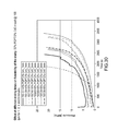
- FIGS. 35A-35B illustrate the capacity of an exemplary semi-solid cathode formulation as a function of charge and discharge rate, and a sample charge/discharge curve.
- FIGS. 36A-36B illustrate the capacity of an exemplary semi-solid cathode formulation as a function of charge and discharge rate, and a sample charge/discharge curve.
- FIGS. 37A-37B illustrate the capacity of an exemplary semi-solid cathode formulation as a function of charge and discharge rate, and a sample charge/discharge curve.
- FIGS. 38A-38B illustrate the capacity of an exemplary semi-solid cathode formulation as a function of charge and discharge rate, and a sample charge/discharge curve.
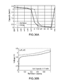
- FIGS. 39A-39B illustrate the performance of a semi-solid based electrochemical cell over 100 cycles, and a sample charge/discharge curve.
- FIGS. 40A-40B illustrate the performance of a semi-solid based electrochemical cell over 30 cycles, and a sample charge/discharge curve.
- Embodiments described herein generally relate to semi-solid suspensions, and more particularly to systems and methods for preparing semi-solid suspensions for use as electrodes in electrochemical devices such as, for example, batteries.
- a method for preparing a semi-solid electrode includes combining a quantity of an active material with a quantity of an electrolyte to form an intermediate material. The intermediate material is then combined with a conductive additive to form an electrode material. The electrode material is mixed to form a suspension having a mixing index of at least about 0.80 and is then formed into a semi-solid electrode.
- the stored energy or charge capacity of a manufactured battery is a function of: (1) the inherent charge capacity of the active material (mAh/g), (2) the volume of the electrodes (cm 3 ) (i.e., the product of the electrode thickness, electrode area, and number of layers (stacks)), and (3) the loading of active material in the electrode media (e.g., grams of active material per cm 3 of electrode media). Therefore, to enhance commercial appeal (e.g., increased energy density and decreased cost), it is generally desirable to increase the areal charge capacity (mAh/cm 2 ) of electrodes.
- Embodiments of semi-solid electrode compositions and methods of preparation described herein can be manufactured directly with the semi-solid suspension, thereby avoiding the use of conventional binding agents and the electrode casting, drying, and calendering steps altogether.
- Some benefits of this approach include, for example: (i) simplified manufacturing with less equipment (i.e., less capital intensive), (ii) the ability to manufacture electrodes of different thicknesses (e.g., by simply changing a forming die dimension), (iii) processing of thicker (>200 ⁇ m) and higher capacity (mAh/cm 2 ) electrodes, thereby decreasing the volume, mass, and cost contributions of inactive components with respect to active material, and (iv) the elimination of binding agents (e.g., PVdF), thereby reducing tortuosity and increasing ionic conductivity of the electrode, as well as increasing safety by excluding binders that can contribute to exothermic reactions.
- binding agents e.g., PVdF
- the term “about” generally means plus or minus 10% of the value stated, e.g. about 5 would include 4.5 to 5.5, about 10 would include 9 to 11, about 100 would include 90 to 110.
- Embodiments described herein relate generally to electrochemical devices such as, for example, lithium ion batteries, however, the systems, methods and principles described herein are applicable to all devices containing electrochemically active media. Said another way, any electrodes and/or devices including at least an active material (source or sink of charge carriers), an electronically conducting additive, and an ionically conducting media (electrolyte) such as, for example, batteries, capacitors, electric double-layer capacitors (e.g., Ultracapacitors), pseudo-capacitors, etc., are within the scope of this disclosure.
- a method of preparing a semi-solid electrode can include combining a quantity of an active material with a quantity of an electrolyte to form an intermediate material.
- the intermediate material is combined with an electrolyte and mixed to form an electrode material.
- the electrode material is mixed until a substantially stable suspension forms that has a mixing index of at least about 0.8, at least about 0.9, at least about 0.95, or at least about 0.975, inclusive of all ranges therebetween.
- the electrode material is mixed until the electrode material has an electronic conductivity of at least about 10 ⁇ 6 S/cm, at least about 10 ⁇ 5 S/cm, at least about 10 ⁇ 4 S/cm, at least about 10 ⁇ 3 S/cm, or at least about 10 ⁇ 2 S/cm, inclusive of all ranges therebetween. In some embodiments, the electrode material is mixed until the electrode material has an apparent viscosity of less than about 100,000 Pa-s, less than about 10,000 Pa-s, or less than about 1,000 Pa-s, at an apparent shear rate of about 1,000 s ⁇ 1 , inclusive of all ranges therebetween.
- the quantity of active material included in the electrode material can be about 20% to about 75% by volume, about 40% to about 75% by volume, or about 60% to about 75% by volume, inclusive of all ranges therebetween.
- the quantity of electrolyte included in the electrode material can be about 25% to about 70% by volume, about 30% to about 50% by volume, or about 20% to about 40% by volume, inclusive of all ranges therebetween.
- the quantity of conductive material included in the electrode material can be about 0.5% to about 25% by volume, or about 1% to about 6% by volume, inclusive of all ranges therebetween.
- the mixing of the electrode material can be performed with, for example, any one of a high shear mixer, a planetary mixer, a centrifugal planetary mixture, a sigma mixture, a CAM mixture and/or a roller mixture.
- the mixing of the electrode material can supply a specific mixing energy of at least about 90 J/g, at least about 100 J/g, about 90 J/g to about 150 J/g, or about 100 J/g to about 120 J/g, inclusive of all ranges therebetween.
- electroactive materials for the positive electrode in a lithium system include the general family of ordered rocksalt compounds LiMO 2 including those having the ⁇ -NaFeO 2 (so-called “layered compounds”) or orthorhombic-LiMnO 2 structure type or their derivatives of different crystal symmetry, atomic ordering, or partial substitution for the metals or oxygen.
- M comprises at least one first-row transition metal but may include non-transition metals including but not limited to Al, Ca, Mg, or Zr. Examples of such compounds include LiCoO 2 , LiCoO 2 doped with Mg, LiNiO 2 , Li(Ni, Co, Al)O 2 (known as “NCA”) and Li(Ni, Mn, Co)O 2 (known as “NMC”).
- exemplary electroactive materials includes those of spinel structure, such as LiMn 2 O 4 and its derivatives, so-called “layered spinel nanocomposites” in which the structure includes nanoscopic regions having ordered rocksalt and spinel ordering, olivines LiMPO 4 and their derivatives, in which M comprises one or more of Mn, Fe, Co, or Ni, partially fluorinated compounds such as LiVPO 4 F, other “polyanion” compounds as described below, and vanadium oxides V x O y including V 2 O 5 and V 6 O 11 .
- spinel structure such as LiMn 2 O 4 and its derivatives
- olivines LiMPO 4 and their derivatives in which M comprises one or more of Mn, Fe, Co, or Ni
- partially fluorinated compounds such as LiVPO 4 F, other “polyanion” compounds as described below
- vanadium oxides V x O y including V 2 O 5 and V 6 O 11 .
- the active material comprises a transition metal polyanion compound, for example as described in U.S. Pat. No. 7,338,734.
- the active material comprises an alkali metal transition metal oxide or phosphate, and for example, the compound has a composition A x (M′ 1 ⁇ a M′′ a )y(XD 4 ) z , A x (M′ 1 ⁇ a M′′ a )y(DXD 4 ) z , or A x (M′ 1 ⁇ a M′′ a )y(X 2 D 7 ) z , and have values such that x, plus y(1 ⁇ a) times a formal valence or valences of M′, plus ya times a formal valence or valence of M′′, is equal to z times a formal valence of the XD 4 , X 2 D 7 , or DXD 4 group; or a compound comprising a composition (A 1 ⁇ a M′′ a )
- A is at least one of an alkali metal and hydrogen
- M′ is a first-row transition metal
- X is at least one of phosphorus, sulfur, arsenic, molybdenum, and tungsten
- M′′ any of a Group IIA, IIIA, IVA, VA, VIA, VIIA, VIIIA, IB, IIB, IIIB, IVB, VB, and VIB metal
- D is at least one of oxygen, nitrogen, carbon, or a halogen.
- the positive electroactive material can be an olivine structure compound LiMPO 4 , where M is one or more of V, Cr, Mn, Fe, Co, and Ni, in which the compound is optionally doped at the Li, M or O-sites.
- the positive active material comprises a thermally stable, transition-metal-doped lithium transition metal phosphate having the olivine structure and having the formula (Li 1 ⁇ x l x )MPO 4 , where M is one or more of V, Cr, Mn, Fe, Co, and Ni, and Z is a non-alkali metal dopant such as one or more of Ti, Zr, Nb, Al, or Mg, and x ranges from 0.005 to 0.05.
- the lithium transition metal phosphate material has an overall composition of L 1 ⁇ x ⁇ z M 1+z PO4, where M comprises at least one first row transition metal selected from the group consisting of Ti, V, Cr, Mn, Fe, Co and Ni, where x is from 0 to 1 and z can be positive or negative. M includes Fe, z is between about 0.15 and ⁇ 0.15.
- the material can exhibit a solid solution over a composition range of O ⁇ x ⁇ 0.15, or the material can exhibit a stable solid solution over a composition range of x between 0 and at least about 0.05, or the material can exhibit a stable solid solution over a composition range of x between 0 and at least about 0.07 at room temperature (22-25° C.).
- the material may also exhibit a solid solution in the lithium-poor regime, e.g., where x ⁇ 0.8, or x ⁇ 0.9, or x ⁇ 0.95.
- Such fluorides may be used as the positive electrode in a lithium battery.
- the redox-active electrode material comprises carbon monofluoride or its derivatives.
- the material undergoing displacement or conversion reaction is in the form of particulates having on average dimensions of 100 nanometers or less.
- the material undergoing displacement or conversion reaction comprises a nanocomposite of the active material mixed with an inactive host.
- slurry components can be mixed in a batch process e.g., with a batch mixer that can include, e.g., a high shear mixture, a planetary mixture, a centrifugal planetary mixture, a sigma mixture, a CAM mixture, and/or a roller mixture, with a specific spatial and/or temporal ordering of component addition, as described in more detail herein.
- slurry components can be mixed in a continuous process (e.g. in an extruder), with a specific spatial and/or temporal ordering of component addition.
- process conditions can be selected and/or modified to control the electrical, rheological, and/or compositional (e.g., uniformity) properties of the prepared slurry.
- the mixing element e.g., roller blade edge
- the minimum gap between which fluid is being flowed in the mixing event e.g. distance from roller blade edge to mixer containment wall
- the shear rate is accordingly between about 1 and about 10,000 inverse seconds. In some embodiments the shear rate can be less than 1 inverse second, and in others it is greater than 10,000 inverse seconds.
- the process conditions can be selected to produce a prepared slurry having a mixing index of at least about 0.80, at least about 0.90, at least about 0.95, or at least about 0.975. In some embodiments, the process conditions can be selected to produce a prepared slurry having an electronic conductivity of at least about 10 ⁇ 6 S/cm, at least about 10 ⁇ 5 S/cm, at least about 10 ⁇ 4 S/cm, at least about 10 ⁇ 3 S/cm, or at least about 10 ⁇ 2 S/cm.
- the process conditions can be selected to produce a prepared slurry having an apparent viscosity at room temperature of less than about 100,000 Pa-s, less than about 10,000 Pa-s, or less than about 1,000 Pa-s, all at an apparent shear rate of 1,000 s ⁇ 1 . In some embodiments, the process conditions can be selected to produce a prepared slurry having two or more properties as described herein.
- the mixing and forming of a semi-solid electrode generally includes: (i) raw material conveyance and/or feeding, (ii) mixing, (iii) mixed slurry conveyance, (iv) dispensing and/or extruding, and (v) forming.
- multiple steps in the process can be performed at the same time and/or with the same piece of equipment.
- the mixing and conveyance of the slurry can be performed at the same time with an extruder.
- Each step in the process can include one or more possible embodiments.
- each step in the process can be performed manually or by any of a variety of process equipment.
- Each step can also include one or more sub-processes and, optionally, an inspection step to monitor process quality.
- Raw material conveyance and/or feeding can include: batch based manual weighing of material with natural feeding (e.g., allowing the mixer to accept material into the mixture without external force), batch based manual weighing of material with forced feeding either by a piston mechanism or a screw-based “side stuffer,” gravimetric screw solids feeders with natural feeding (e.g., feed at the rate which the mixer can naturally accept material), gravimetric screw solids feeders with forced feeding (e.g., units sold by Brabender Industries Inc combined with a piston mechanism or a screw-based ‘side stuffer’), and/or any other suitable conveyance and/or feeding methods and/or any suitable combination thereof.
- natural feeding e.g., allowing the mixer to accept material into the mixture without external force
- batch based manual weighing of material with forced feeding either by a piston mechanism or a screw-based “side stuffer”
- gravimetric screw solids feeders with natural feeding e.g., feed at the rate which the mixer can naturally accept material
- the slurry can be conveyed and/or pressurized, for example using a piston pump, peristaltic pump, gear/lobe pump, progressing cavity pump, single screw extruder, conveying section of a twin screw extruder, and/or any other suitable conveying device.
- the torque and/or power of the conveying device, the pressure at the conveying device exit, the flow rate, and/or the temperature can be measured, monitored and/or controlled during the conveying and/or pressurizing.
- the slurry can be dispensed and/or extruded.
- the slurry can be dispensed and/or extruded using, for example, a “hanger die” sheet extrusion die, a “winter manifold” sheet extrusion die, a profile-style sheet extrusion die, an arbitrary nozzle operable to apply a continuous stream of material to a substrate, injection into a mold of the correct size and shape (e.g., filling a pocket with material), and/or any other suitable dispensing device.
- the slurry after dispensing the slurry can be formed into a final electrode.
- the slurry can be calendar roll formed, stamped and/or pressed, subjected to vibrational settling, and/or cut in discrete sections. Additionally, in some embodiments, unwanted portions of material can be removed (e.g., masking and cleaning) and optionally recycled back into the slurry manufacturing process.
- the mixing device can be operable to control the flowability of the slurry regulating the temperature, and/or to control the slurry homogeneity by modulating the chemical composition.
- the semi-solid suspension can be transferred from the batch mixer to another piece of processing equipment, e.g., an extruder.
- the transfer method can be chosen so as to minimize electrolyte losses, to not appreciably disrupt the slurry state, and/or to not introduce other processing difficulties, such as entrainment of ambient gases.
- an extruder e.g., twin screw
- mixing and material conveyance occur together, thus eliminating a process step.
- some electrolyte loss can be tolerated and used as a control specification, and the amount that can be tolerated generally decreases as electrolyte volume fraction increases and/or mixing index increases.
- the maximum electrolyte loss can be controlled to less than about 39%, to less than about 33%, or to less than about 27%.
- the maximum electrolyte loss can be controlled to less than about 5%, to less than about 4%, or to less than about 3%.
- the maximum electrolyte loss can be controlled to less than about 5%, to less than about 4%, or to less than about 3%.
- Component concentrations can be calculated to determine and/or predict tolerable losses, and vary according to the specific components. In other embodiments, loss tolerances will be higher while in others they will be more restrictive.
- the composition of the slurry and the mixing process can be selected to homogeneously disperse the components of the slurry, achieve a percolating conductive network throughout the slurry and sufficiently high bulk electrical conductivity, which correlates to desirable electrochemical performance as described in further detail herein, to obtain a rheological state conducive to processing, which may include transfer, conveyance (e.g., extrusion), dispensing, segmenting or cutting, and post-dispense forming (e.g., press forming, rolling, calendering, etc.), or any combination thereof.
- transfer conveyance.g., extrusion
- dispensing segmenting or cutting
- post-dispense forming e.g., press forming, rolling, calendering, etc.
- FIG. 1 illustrates the electronic conductivity of different slurry formulations
- FIG. 2 illustrates the yield stress, a rheological parameter, of the same slurry formulations, prepared using a variety of mixing methods including high sheared mixing, planetary mixing, planetary mixing with ultrasonication, handmixing, and handmixing with ultrasonication.
- the mixing method can be selected to achieve one or more desired characteristic of the final prepared slurry.
- maximizing a performance measure is not always the most desirable characteristic of the final prepared slurry. Said another way, although producing a slurry having a high electronic conductivity is generally desirable, if the final slurry is not readily formable and/or stable, the high electronic conductivity for that particular slurry would not be beneficial. Similarly, producing a slurry that is easily formable and/or very stable, but with a low electronic conductivity is also not desirable.
- compositional homogeneity of the slurry will generally increase with mixing time, although the microstructure of the slurry may be changing as well.
- the compositional homogeneity of the slurry suspension can be evaluated quantitatively by an experimental method based on measuring statistical variance in the concentration distributions of the components of the slurry suspension.
- mixing index is a statistical measure, essentially a normalized variance or standard deviation, describing the degree of homogeneity of a composition. (See, e.g., Erol, M, & Kalyon, D. M., Assessment of the Degree of Mixedness of Filled Polymers , Intern. Polymer Processing XX (2005) 3, pps. 228-237).
- the homogeneity of the slurry can be described by its compositional uniformity (+x %/ ⁇ y %), defined herein as the range: (100% ⁇ y)*C to (100%+x)*C. All of the values x and y are thus defined by the samples exhibiting maximum positive and negative deviations from the mean value C, thus the compositions of all mixed material samples taken fall within this range.
- the basic process of determining mixing index includes taking a number of equally and appropriately sized material samples from the aggregated mix and conducting compositional analysis on each of the samples.
- the sampling and analysis can be repeated at different times in the mixing process.
- the sample size and volume is based on considerations of length scales over which homogeneity is important, for example, greater than a multiple of both the largest solid particle size and the ultimate mixed state average intra-particle distance at the low end, and 1/Nth of the total volume where N is the number of samples at the high end.
- the samples can be on the order of the electrode thickness, which is generally much smaller than the length and width of the electrode. Capabilities of certain experimental equipment, such as a thermo-gravimetric analyzer (TGA), will narrow the practical sample volume range further.
- TGA thermo-gravimetric analyzer
- Sample “dimension” means the cube root of sample volume.
- the mixing index at a given mixing time is defined, according to the present embodiments, to be equal to 1 ⁇ / ⁇ ref , where ⁇ is the standard deviation in the measured composition (which may be the measured amount of any one or more constituents of the slurry) and ⁇ ref is equal to [C(1 ⁇ C)] 1/2 , where C is the mean composition of the N samples, so as the variation in sample compositions is reduced, the mixing index approaches unity.
- time and “duration” are general terms speaking to the progression of the mixing event.
- Other indicators of mixing such as, for example, cumulative energy input to the mix, number of armature, roller, mixing blade, or screw rotations, distance traveled by a theoretical point or actual tracer particle in the mix, temperature of the mix (which is affected by viscous heating), certain dimensionless numbers commonly used in engineering analysis, and others can be used to predict or estimate how well the slurry is mixed.
- This mixture can be used to build electrodes with an area of 80 cm 2 , and a thickness of 500 ⁇ m.
- the specific dimension of interest is in the middle of this range, i.e., 500 ⁇ m. Accordingly, to quantify mixing index, the samples are taken with a special tool having a cylindrical sampling cavity with a diameter of 0.5 mm and a depth of 0.61 mm. In this example, the sample volume would be 0.12 mm 3 .
- the sample volume selection for mixing index measurement is guided by length scales over which uniformity is important.
- this length scale is the thickness (e.g., 250 ⁇ m to 2,000 ⁇ m) of an electrode in which the slurry will be used.
- the electrode is 0.2 mm thick, the sample volume should preferably be between 0.0025 and 0.025 mm 3 .
- the electrode is 2.0 mm thick, the sample volume should preferably be between 2.5 mm 3 and 25 mm 3 .
- the sample volume by which mixing index is evaluated is the cube of the electrode thickness ⁇ 10%. In some embodiments, the sample volume by which mixing index is evaluated is 0.12 mm 3 ⁇ 10%. In one embodiment, the mixing index is measured by taking N samples where N is at least 9, each sample having the sample volume, from a batch of the electrode slurry or from a formed slurry electrode that has a volume greater than the total volume of the N samples. Each of the sample volumes is heated in a thermo gravimetric analyzer (TGA) under flowing oxygen gas according to a time-temperature profile wherein there is 3 minute hold at room temperature, followed by heating at 20° C./min to 850° C., with the cumulative weight loss between 150° C. and 600° C. being used to calculate the mixing index. Measured in this manner, the electrolyte solvents are evaporated and the measured weight loss is primarily that due to pyrolysis of carbon in the sample volume.
- TGA thermo gravimetric analyzer
- a Brabender Batch Mixer can be used to mix the slurry at 30 to 100 rpm.
- the slurry can be mixed at 10-200 rpm or any other suitable speed.
- the speed of the mixer can be varied throughout the mix cycle, for example, a lower mix speed can be used to incorporate the ingredients, and a higher mix speed can be used to homogenize the slurry.
- the mixing speed can be varied during the addition of the ingredients.
- the total mix time can be between 1 and 100 minutes. In other embodiments, any appropriate mix time can be selected.
- the mixer can supply a specific mixing energy of between 3 and 2,000 J/g. In other embodiments, the mixer can supply any suitable amount of mixing energy.
- conductive additives can have technical characteristics and morphologies (i.e., hierarchical clustering of fundamental particles) that influence their dispersive and electrochemical behavior in dynamic and/or static suspensions.
- Characteristics that can influence dispersive and electrochemical behavior of conductive additives include surface area and bulk conductivity.
- morphological factors can impact the dispersion of the carbon particles.
- the primary carbon particles have dimensions on the order of nanometers, the particles typically exist as members of larger aggregates, consisting of particles either electrically bound (e.g., by van der Waals forces) or sintered together.
- Such agglomerates may have dimensions on the order of nanometers to microns.
- aggregates can form larger scale clusters commonly referred to as agglomerates, which can have dimensions on the order of microns to tens of microns.
- fluid shearing forces e.g., imparted during mixing
- the additives can disrupt the carbon network, for example, by overcoming agglomerate and aggregate binding forces.
- the additives can be present in a finer scale (more granular and more homogeneous) dispersion of the conductive solid.
- Mixing can also densify clusters of the conductive solid. In some embodiments, mixing can both disrupt the conductive network and densify clusters, which can sever electrical conduction pathways and adversely impact electrochemical performance.
- FIG. 3A-3C are schematic diagrams of an electrochemically active slurry containing active material 310 and conductive additive 320 in which the quantity of the conductive additive 320 is not enough to form a conductive network.
- FIG. 3A depicts a slurry before any mixing energy has been applied or after only minimal mixing energy has been applied.
- FIG. 3B depicts the slurry with an optimal amount of mixing energy applied and
- FIG. 3C depicts the slurry with an excessive amount of mixing energy applied. As illustrated in FIG. 3B even with the optimal amount of mixing, the amount of conductive additive 320 is not adequate to create an appreciable conductive network throughout the electrode volume.
- FIG. 4A-4C are schematic diagrams of an electrochemical active slurries containing an active material 410 and conductive additive 420 . Contrary to FIG. 3A-C , in this example the quantity of the conductive additive 420 is enough to form a conductive network. As shown in FIG. 4A , the conductive additive 420 is largely in the form of unbranched agglomerates 430 . The homogeneity of the conductive additive 420 could be characterized as non-uniform at this stage. As shown in FIG.
- FIGS. 3A-3C and FIGS. 4A-4C illustrate that an electrochemically active slurry can include a minimum threshold of conductive additive 320 / 420 loading, and an optimal processing regime between two extremes (i.e., the slurry depicted in FIG. 4B ).
- a semi-solid suspension can be formed having an appreciable conductive interparticle network (e.g., conductive additive agglomerate 440 network).
- the specific mixing energy applied can be about 90 J/g to about 150 J/g, e.g., at least about 90 J/g, at least about 100 J/g, at least about 120 J/g or at least about 150 J/g inclusive off all ranges therebetween.
- the quantity of a conductive additive i.e., the mass or volume fraction of the conductive additive (also referred to herein as the conductive additive “loading”) that is used in a given mixture relative to other components, such as an active material, that is suitable for the mixture to achieve a specified level of bulk electrical conductivity depends on the cluster state. Percolation theory can be used to select a loading of conductive additive. Referring now to FIG. 5 , a plot of conductivity of an electrochemical slurry versus conductive additive loading is shown. As the loading of the conductive additive increases, so does the conductivity of the slurry. Three regions of conductivity are depicted on FIG. 5 . At low loadings of conductive additive 522 , the slurry has relatively low conductivity.
- this slurry with low conductive additive loading 522 can correspond to the slurry depicted in FIG. 3A-3C , in which there is insufficient conductive material to form an appreciable interparticle network.
- a percolating network 524 begins to form as chains of conductive additive are able to at least intermittently provide connectivity between active particles.
- a relatively stable interparticle networks 530 is formed. The shape and height of the percolation curve can be modulated by the method of mixing an properties of the conductive additive, as described herein.
- the amount of conductive additive used in a slurry can be constrained by other considerations. For example, maximizing battery attributes such as energy density and specific energy is generally desirable and the loading of active materials directly influences those attributes. Similarly stated, the quantity of other solids, such as active material, must be considered in addition to the loading of conductive material.
- the composition of the slurry and the mixing process described herein can be selected to obtain a slurry of relatively uniform composition, while enabling clustering of the conductive additive to improve electrical conductivity. In other words, the slurry can be formulated and mixed such that a minimum threshold of conductive additive is included to form the interparticle network after an appropriate amount of mixing, thereby maximizing the active material loading.
- the amount of conductive additive in the slurry can be about 0.5% to about 25% by volume, e.g., about 0.5%, 1%, 6%, or 25% by volume, inclusive of all ranges therebetween.
- the electronic conductivities of the prepared slurries can be at least about 10 ⁇ 6 S/cm, at least about 10 ⁇ 5 S/cm, at least about 10 ⁇ 4 S/cm, at least about 10 ⁇ 3 S/cm, or at least about 10 ⁇ 2 S/cm, inclusive of all ranges therebetween.
- the maximum conductive additive loading at zero active material loading and the maximum active material loading at zero conductive additive loading depend on the type of conductive additive and active material being used. For example, a linear-type trend of active material to conductive additive, having a constant rheological parameter value (e.g., effective viscosity at a given shear rate) is generally observed, but other shapes (bowed out, bowed in, or with an inflection point) are possible. Said another way, a constant rheological parameter value can define a region in which “workable” formulations can be selected. The region can depend on, for example, materials being used, and can also be determined experimentally.
- a constant rheological parameter value e.g., effective viscosity at a given shear rate
- a workable formulation can have up to about 20% by volume of a conductive additive with a surface area less than 40 m 2 /g, up to about 5% by volume of a conductive additive with a surface area less than 1,000 m 2 /g, and up to about 52% by volume of lithium titanate with a tap density of 1.3 g/cc.
- the electrochemically active slurry it is desirable for the electrochemically active slurry to be “workable,” in order to facilitate material handling associated with battery manufacturing. For example, if a slurry is too fluid it can be compositionally unstable. In other words, the homogeneity can be lost under exposure to certain forces, such as gravity (e.g., solids settling) or centrifugal forces. If the slurry is unstable, solid phase density differences, or other attributes, can give rise to separation and/or compositional gradients. Said another way, if the slurry is overly fluidic, which may be the result of low solids loadings or a significantly disrupted conductive network, the solids may not be sufficiently bound in place to inhibit particle migration.
- gravity e.g., solids settling
- centrifugal forces e.g., centrifugal forces
- an electrochemically active slurry if an electrochemically active slurry is too solid, the slurry may break up, crumble, and/or otherwise segregate into pieces, which can complicate processing and dimensional control. Formulating the slurry within a band of adequate workability can facilitate easier slurry-based battery manufacturing.
- Workability of a slurry can typically be quantified using rheological parameters which can be measured using rheometers. Some examples of different types of rheometers that can be used to quantify slurry workability include: strain or stress-controlled rotational, capillary, slit, and extensional.
- the mixing speed (which may be fixed, staged, continuously varied, oscillated, and/or controlled according to a feedback signal) and duration of mixing (or of certain stages) can affect the establishment and stability of electrical conductivity in the carbon matrix and corresponding voltage efficiency in the cell, and the compositional homogeneity amongst all material components.
- the formation and stability of electrical conductivity can be diminished by high shear or extended mixing.
- High shear and/or extended mixing can facilitate homogeneity, which can support local electrode balancing and long cycle life.
- material “workability,” which can enable more efficient processing and handling during manufacture and/or long term local compositional stability (e.g., no “settling” of solids within the finished electrode), can also be affected by mixing speed and duration.
- Feeding of components to the mixer, extruder, or other combining equipment can be facilitated by ram feeding chutes or similar fixed displacement devices.
- the rate at which components are fed into the combining equipment can be set or controlled, which can limit shear history accumulation for material that is added first.
- Active materials and conductive additives of different types, structure, morphology, and/or made by different processes can have different interactions with different components in the mixtures. This can result in slurries having the same solid to electrolyte ratio with different rheological properties.
- the ratios between active material, conductive additive, and electrolyte can affect the stability, workability, and/or rheological properties of the slurry.
- FIG. 6A-6C depict electrode slurry mixtures with different loadings of active material and conductive additive relative to the electrolyte.
- a low loading 610 FIG. 6A
- phase separation i.e., separation of the of the active material and conductive additive (solid phase) from the electrolyte (liquid phase)
- phase separation i.e., separation of the of the active material and conductive additive (solid phase) from the electrolyte (liquid phase
- the “workable” slurries with different solids loadings can be evaluated for flowability and processability.
- the rheological behavior of the slurries can indicate processability under pressure driven flows, such as in a single or twin screw extrusion and/or flow through a die.
- the slurries can be categorized as “suspensions” with different loading levels and a low viscosity liquid medium/matrix.
- the flow behavior of such suspensions can be dependent on size distribution, shape and volume fraction of solid particles, particle-particle and particle-matrix interactions, and matrix rheology.
- slurries can be selected based on rheology, which can be used to predict favorable processability of the slurries and/or desired electrochemical performance.
- the rheology of the “workable” slurries can be governed by the compositional formulation, e.g., different active materials and conductive additives loaded at various concentrations and/or homogeneity of the slur
- a type and loading level of conductive additive can be selected, which can form a gel like network that holds the suspension together and can prevent separation.
- different types of conductive additives can, depending on their structure, form slurries with different rheological characteristics at the same loading levels.
- the type of active material incorporated into the formulation at given volume loading level and type of conductive additive can effect the rheological properties of the slurries.
- the particle size, aspect ratio and particle size distribution of the solids e.g., the active material and/or the conductive additive
- the particle size, aspect ratio and particle size distribution of the solids can impact the rheology of the slurry.
- the conductive additive can affect the rheology of the suspension.
- increasing concentrations of active materials can contribute to the rheology of the slurry by increasing the shear viscosity of the suspension.
- FIG. 7 illustrates rheological characteristics including the apparent viscosity ( ⁇ appr Pa-s) and apparent shear rate ( ⁇ app s ⁇ 1 ) for various formulations of slurries that are formulated from about 35% to about 50% by volume NMC and about 6% to about 12% by volume of conductive additive C45.
- FIG. 8 illustrates the rheological characteristics described herein for various formulations of slurries formulated from about 35% to about 50% by volume graphite (PGPT) and about 2% to about 10% by volume of the conductive additive C45.
- PGPT graphite
- the apparent viscosity of the slurries described herein decreases as the apparent shear rate increases.
- a capillary rheometer can be utilized to characterize rheological behavior of slurries with different compositions.
- Capillary rheometers use a pressure driven flow to determine, for example, processability of a suspension by subjecting the material to shear rates higher than 10 ⁇ 1 s ⁇ 1 .
- the suspension in a reservoir/barrel can flow through a capillary tube/die under pressure generated by a piston.
- the flow and deformation behavior of the suspension can be characterized through generating flow rate versus pressure drop data by using various capillary dies with different diameters, lengths and entrance angels.
- the flow of a suspension can be described by different mechanisms depending on the suspension properties, i.e., yield stress, matrix viscosity, loading levels, particle interaction, and wall slip behavior controlled by such properties.
- the suspension can flow with or without slip.
- the suspension can flow like a plug without deformation at stresses below the yield stress.
- the highly loaded slurry suspension can be characterized by a strong slip mechanism and with a high yield stress of around 35,000 Pa.
- the slurry suspensions can be prone to separation and flow instabilities, structure development, mat formation and/or binder filtration when flowing under a critical shear stress values due to a low viscosity liquid matrix in the formulation. Such behavior can be characterized using a capillary rheometer using a small diameter and a long L/D.
- the compositional formulation, especially conductive carbon loading levels, and the extrusion temperature can impact such structural changes during a pressure driven flow.
- FIG. 9 and FIG. 10 illustrate time-pressure graphs for various formulations of a first slurry that includes about 35%-50% NMC and about 6%-12% C45 ( FIG.
- the apparent viscosity of the prepared slurry at an apparent shear rate of about 1,000 s ⁇ 1 can be less than about 100,000 Pa-s, less than about 10,000 Pa-s, or less than about 1,000 Pa-s.
- the reciprocal of mean slurry viscosity can be greater than about 0.001 l/(Pa-s).
- Some slurry formulations include three main components such as, for example, active material (e.g., NMC, lithium iron phosphate (LFP), Graphite, etc.), conductive additive (e.g., carbon black), and electrolyte (e.g., a mix of carbonate based solvents with dissolved lithium based salt) that are mixed to form the slurry.
- the three main components are mixed in a batch mixer.
- active materials are first added to the mixing bowl followed by solvents.
- the electrolyte can be incorporated homogeneously with a dense active material without experiencing any ‘backing out’ of material from the mixing section of the mixing bowl to form an intermediate material.
- the conductive additive can be added to this intermediate material (i.e., loose paste), such that it can be evenly incorporated into the mix.
- the active material can tend not to aggregate into clumps.
- the components can be combined using another order of addition, for example, the solvent can be added first to the mixing bowl, then the active material added, and finally the additive can be added.
- the slurry can be mixed using any other order of addition.
- the mixer can add dispersive shear energy to the bulk material being mixed.
- the mixing energy can be normalized to the mass of material being mixed, which can provide a quantifiable metric for how much work was done to mix a given sample.
- mixing energy increases.
- the mixture can exhibit low homogeneity, e.g., material may not be evenly distributed throughout the bulk of the mixture. Additionally, a slurry having had a relatively small amount of mixing energy added can have low flowability and/or formability.
- aggregates of solid material can remain.
- such aggregates can be smaller than is visible to the naked eye, yet, these aggregates can cause the slurry to be “dry” or “crumbly.”
- a slurry having a small amount of mixing energy can exhibit a lack of ductility, which can include the tendency of the material to fracture instead of spread as it is formed.
- a slurry having excessive mixing energy imparted to it can display unstable rheology.
- the carbon network affects mechanical, as well as electronic characteristics of the slurry, formulations which have been over mixed tend to appear “wetter” than slurries subjected to a lesser amount of mixing energy. Slurries having experienced an excessive amount of mixing energy also tend to show poor long term compositional homogeneity as the solids phases tend to settle due to gravitational forces.
- a particular composition can have favorable electrical and/or rheological properties when subject to an appropriate amount of mixing. For any given formulation, there is a range of optimal mixing energies to give acceptable dispersion, conductivity and rheological stability.
- FIGS. 11-13 are plots illustrating an example mixing curve, comparative mixing curves of low and high active material loading for the same carbon additive loading, and comparative mixing curves of low and high carbon additive loading for the same active material loading, respectively.
- FIG. 11 depicts a mixing curve including the specific mixing energy 1110 , the speed 1140 , and the torque 1170 , of slurry, according to an embodiment.
- the first zone 1173 shows the addition of the raw materials.
- the active material is added to the mixer, then the electrolyte, and finally the conductive additive (carbon black).
- the carbon additive takes the longest time to add to the mixing bowl due to the difficulty of incorporating a light and fluffy powder into a relatively dry mixture.
- the torque curve 1170 provides an indication of the viscosity, particularly, the change in viscosity. As the viscosity of the mixture increases with the addition of the carbon black, the torque required to mix the slurry increases. The increasing viscosity is indicative of the mechanical carbon network being formed.
- the mixing curve shows the dispersion of the raw materials and relatively lower viscosity as evidenced by the decreased torque required to mix the slurry.
- FIG. 12 illustrates the difference between a low and high loading of active materials. It can be seen from this curve that the length of time needed to add the conductive carbon additive is approximately equal for low and high active loadings, but the overall torque (and consequently the mixing energy) is much higher for the higher active loading. This is indicative of a much higher viscosity.
- FIG. 13 illustrates the difference between a low and high conductive carbon additive loading for the same active material loading.
- the mixing curve for the high carbon loading includes the specific mixing energy 1310 , the speed 1340 and the torque 1373 .
- the first zone 1373 shows the addition of raw materials.
- the torque required to mix the slurry increases as seen in the first mixing zone 1375 .
- the increasing viscosity is indicative of the carbon network being formed.
- the mixing curve shows the dispersion of the raw materials and relatively lower viscosity as evidenced by the decreased torque required to mix the slurry. It should be noted that the time needed to add the carbon conductive additive is much longer for the high carbon loading and the overall torque (and mixing energy) is also much higher. This mixing curve illustrates that carbon loading has a much higher impact on material viscosity than active material loading.
- compositional homogeneity of the slurry will generally increase with mixing time and the compositional homogeneity can be characterized by the mixing index.
- FIG. 14 illustrates the specific energy input required to achieve different mixing indexes for slurries of different conductive additive loadings. As shown, a higher amount of specific energy input is required to achieve the desired specific index, e.g., about 0.95 as the vol % of conductive additive is increased in the slurry formulation.
- the slurry is mixed until the slurry has a mixing index of about 0.8, of about 0.9, of about 0.95 or about 0.975, inclusive of all mixing indices therebetween.
- FIG. 15 illustrates the effect of mixing on certain slurry parameters that include the mixing index and the electronic conductivity of the slurry, according to an embodiment.
- the mixing index 1580 rises monotonically while electronic conductivity 1590 initially increases (as conductive network is dispersed within the media), achieves a maximum value, and then decreases (network disruption due to “over mixing”).
- processing parameters can influence electronic conductivity, which is an important parameter for electrochemically active slurries.
- FIG. 16 demonstrates that processing time can be selected to alter electronic conductivity and morphology of the semi-solid electrodes. Examples of such results are shown in FIG. 16 , which depicts the conductivity of certain slurries that include about 35% NMC and about 2%-15% conductive additive C45, as a function of mixing time. As seen in FIG. 16 , longer mixing time can yield samples with lower conductivities.
- FIGS. 17A-17D are micrographs of a slurry subjected to two different mixing times showing that carbon conductive additive agglomeration tends to increase in a sample mixed for a longer time 1710 ( FIG. 17A-17B ), as compared to a sample that was mixed for a shorter time 1720 ( FIG. 17C-17D ).
- the mixing time can have a simultaneously impact mixing index and conductivity of an electrode slurry.
- FIG. 18 illustrates the effect of mixing time on the mixing index and conductivity of various slurry formulations that include about 45%-50% NMC and about 8% C45.
- the mixing index is measured by taking sample volumes of 0.12 mm 3 from a batch of the electrode slurry that has a total volume greater than the sum of the individual sample volumes.
- Each sample volume of slurry is heated in a thermo gravimetric analyzer (TGA) under flowing oxygen gas according to a time-temperature profile beginning with a 3 minute hold at room temperature, followed by heating at 20° C./min to 850° C., with the cumulative weight loss between 150° C.
- TGA thermo gravimetric analyzer
- the mixing index is observed to increase but the conductivity is observed to decrease with increased mixing times.
- a mixing time of about 2 minutes provided a good compromise between the conductivity and the mixing index, e.g., the slurry composition composed of 50% NMC and 8% C45 was observed to have a mixing index of about 0.95 and a conductivity of about 0.02 S/cm. Any further mixing has a negative impact on the conductivity.
- FIG. 19 illustrates the effect of mixing time on the mixing index and conductivity of various slurry formulations that include about 45%-50% PGPT and about 2%-4% C45.
- the conductivity is observed to initially rise, peaking at a 4 minute mixing time, and then decrease by more than a factor of two at 24 minutes—consistent with the trend described in FIG. 15 . Therefore the mixing times required to get an optimal mixing index and conductivity of a slurry depend on the slurry formulation.
- shear rate can influence mixing dynamics and conductivity.
- the selection of mixing element rotation speed, container and/or roller size, clearance dimensions/geometry, and so forth can have an effect on conductivity.
- FIG. 20 is a plot depicting conductivity as a function of mixing time for two different shear conditions. As shown, the slurry subjected to the lower shear mixing 2010 is less sensitive to over mixing. The slurry subject to higher shear mixing 2020 has a slightly higher peak conductivity, reaches the maximum conductivity with less mixing, and is more sensitive to over mixing. In some embodiments, the optimal mixing time can be 20 seconds, 2 minutes, 4 minutes or 8 minutes, inclusive of mixing times therebetween.
- particle size, shape, aspect ratio, and distribution of the solid particles in the slurry suspension can be selected to determine loading levels.
- temperature control during processing can be employed, which can reduce electrolyte evaporation.
- temperature control By controlling the temperature of the slurry, rheology, conductivity, and/or other characteristics of the slurry can be improved.
- the electrolyte can include a mixture of solvents with differing levels of volatility and vapor pressures. Temperature can have an effect on the evaporation rate of this mixture as well as which components will preferentially evaporate before others, which can change the composition and/or the performance of the electrolyte.
- FIG. 21 depicts the percentage loss of electrolyte with temperature and mixing duration. Reduced total electrolyte and loss of the more volatile components of the electrolyte in the slurry mixture can reduce the ionic conductivity of the slurry, subsequently increasing the voltage polarization and decreasing the efficiency and capacity of the battery. By reducing and/or controlling processing temperatures, evaporation and subsequent changes to the composition of the slurry can be decreased, and can lead to a more easily controllable process.
- a “compensation” step can be added to the process.
- This step can include adding a surplus of the electrolyte and/or components of the electrolyte (e.g., the more volatile electrolyte components) during some stage of the processing.
- the stage at which this addition is made could be during initial mixing of the electrolyte, during final cell assembly or at any other step.
- temperature control can also be used to control electrolyte viscosity, which can affect the rheological behavior of the slurry.
- FIG. 22 illustrates the effect of varying temperature on the apparent viscosity and apparent shear stress of an anode slurry composition that includes about 45% PGPT and about 4% C45, according to an embodiment.
- the anode slurry was formulated at a first temperature of ⁇ 2 degrees Celsius and a second temperature of 5 degrees Celsius. As the temperature of the slurry and/or electrolyte decreases, the viscosity increases. As the viscosity of the electrolyte increases, the force it exerts on the solid particles in suspension as it flows increases.
- FIG. 23 illustrates the effect of varying temperature on the apparent viscosity and shear stress of a cathode slurry composition that includes about 50% NMC and about 8% C45, according to an embodiment.
- the cathode slurry was formulated at a first temperature of 5 degrees Celsius and a second temperature of approximately room temperature (RT) (e.g., 25 degrees Celsius). Similar to anode slurry formulation of FIG. 22 , viscosity of the cathode slurry increases with decreasing temperature
- the temperature of the electrolyte and/or the slurry can have an effect on the adhesion of the slurry to other materials, such as process equipment. At low temperatures, the slurry can have a lower level of adhesion to typical materials used in processing. Conversely, when the slurry is applied to a substrate (e.g., a metallic foil or polymer film) to which adhesion is desired, raising the slurry/substrate interface temperature can act to promote adhesion.
- a substrate e.g., a metallic foil or polymer film
- a processing temperature can be approximately 10 degrees Celsius. In some embodiments, the processing temperature can be lower than 10 degrees Celsius.
- the processing temperature can be selected to increase the slurry flow stability, for example, by modulating the viscosity of the liquid phase (e.g. electrolyte). Said another way, for a given flow geometry, slurry composition, and driving force, the slurry may experience loss of compositional uniformity (i.e., segregate) at one temperature, but may experience no loss of compositional uniformity at a different temperature.
- the slurry flow stability can be modified (e.g., by temperature selection) to improve the conveyance of material through process equipment (e.g., extruder, extrusion die, etc.).
- the slurry flow stability can be modified to decrease slurry adhesion to process equipment (e.g., calendar roll, cutting blades, etc.). In some embodiments, the slurry flow stability can be modified to cause desired adhesion to laminating substrates (e.g., metallic foils or polymer films).
- the processing temperature can be selected to minimize, or otherwise control, the amount of electrolyte evaporation. In some embodiments, the processing temperature can be varied throughout the process to achieve the desired characteristics at different steps.
- ultrasonication can be used to modulate the conductive network in slurries.
- vibratory excitation can be applied to mixing devices, conveying/compounding devices, and/or the slurry itself (in a container or in situ).
- conductive additives can have aggregation and agglomeration characteristics (surface energies and interparticle forces) that can be modulated by other means, including: temperature, exposure to light or other tuned radiation, application of electrical or magnetic fields, use of additives in the liquid phase of the slurry, specialized coatings on active materials, addition of chemical moieties to the conductive additive, and/or operation in an electrochemical operational configuration before, during, and/or after one or more process steps.
- a salt can be added before, during and/or after processing.
- Battery electrolyte can include one or more solvents, e.g., various organic carbonates.
- a battery electrolyte can include one more salts.
- the electrolyte can contain other additives, for example, surfactants, dispersants, thickeners, and/or any other suitable agents.
- the additive can modify the properties of the electrolyte, for example to facilitate flowability, processability, compositional stability, workability, and/or overall manufacturability.
- the additive can include, for example, fluorinated carbonate derivatives, such as those developed by Daikin industries.
- additives can modify slurry properties in desirable ways, such as, for example: (1) increasing liquid phase viscosity—which expands the range of shear rates that can be used in processing while maintaining fluid-solid compositional homogeneity, (2) increasing lubricity—which expands the slipping region during flow and preserves homogeneity, and possibly reduces energy inputs related to processing, (3) reducing mixture vapor pressures, leading to reduced losses during processing in unconfined spaces, among others.
- additives such as these may have adverse effects on electrochemical performance, however, the advantages they afford for battery production can outweigh adverse effects.
- the following battery architectures can utilize the approaches described herein: (1) those in which both electrodes are slurry-based, (2) those in which one electrode is slurry-based and the other conventionally cast, (3) those where one electrode is slurry-based and the other is designed to consume and utilize a gas-phase reactant, e.g. oxygen from air.
- Designs can include single anode-cathode pairs (unit cells), prismatic assemblies with a multiplicity of anode/cathode pairs stacked atop one another, spiral wound assemblies, jelly roll assemblies, and other variants.
- the active materials can include lithium titanate, graphite, silicon alloys, tin alloys, silicon-tin alloys, lithium iron phosphate, lithium transition metal oxides, magnesium compounds, bismuth, boron, gallium, indium, zinc, tin, antimony, aluminum, titanium oxide, molybdenum, germanium, manganese, niobium, vanadium, tantalum, iron, copper, gold, platinum, chromium, nickel, cobalt, zirconium, yttrium, molybdenum oxide, germanium oxide, or any other suitable active material.
- the conductive additives can include carbon (high e.g. Ketjen black or low e.g.
- the electrolytes included in the slurries can include ethylene carbonate, propylene carbonate, butylene carbonate, and their chlorinated or fluorinated derivatives, and a family of acyclic dialkyl carbonate esters, such as dimethyl carbonate, diethyl carbonate, ethylmethyl carbonate, dipropyl carbonate, methyl propyl carbonate, ethyl propyl carbonate, dibutyl carbonate, butylmethyl carbonate, butylethyl carbonate, butylpropyl carbonate, y-butyrolactone, dimethoxyethane, tetrahydrofuran, 2-methyl tetrahydrofuran, 1,3-dioxolane, 4-methyl-1,3-dioxolane, diethyl ether, sulfolane, methylsulfolane, acetonitrile, propiononitrile, ethyl acetate, methyl propionat
- the progression of mixing index over time for a fixed RPM (e.g., 100 RPM) mixing speed can depend on the composition of the materials being mixed.
- FIG. 24 illustrates the mixing index at 100 rpm over time for a first cathode composition that includes about 45% NMC and about 8% C45, and a second cathode composition that includes about 50% NMC and about 8% C45.
- the mixing index of FIG. 25 illustrates the mixing index at 100 rpm over time for a first anode composition that includes about 45% PGPT and about 4% C45 and a second anode composition that includes about 50% PGPT and 2% C45.
- the cathode and anode slurries show an increase in the mixing index with mixing time.
- the mixing index can, for example, plateau after a certain mixing time, e.g., 8 minutes, after which any more mixing does not cause an increase in the mixing index.
- different mixing processes can produce different degrees of mixing (i.e., mixing index) and electrical conductivity for the same anode and/or cathode composition.
- FIG. 26 illustrates the mixing index and electrical conductivity for an anode composition that includes about 35% PGPT and about 2% C45, mixed at a fixed mixing speed of 100 RPM for 4 minutes with four different mixing techniques (e.g., hand-mixed, roller, sigma and CAM). As shown, sigma achieves better uniformity (i.e., higher mixing index), but roller achieves higher electrical conductivity.
- FIG. 27 illustrates the mixing index and electrical conductivity for a first cathode composition that includes about 35% NMC and 8% C45 and a second electrode composition that includes about 45% NMC and 8% C45, both mixed at a fixed mixing speed of 100 RPM for 4 minutes with two different mixing techniques (e.g., CAM and roller). While the 35% NMC/8% C45 slurry achieves a higher mixing index with the roller mixer, the 45% NMC/8% C45 slurry achieves a higher mixing index with the CAM roller.
- the type of mixing process used can also have an effect on the conductivity of the slurry.
- FIG. 28 illustrates the mixing index and conductivity of an anode composition that includes about 45% PGPT and about 4% C45, mixed using a first mixing process (e.g., roller blade) or a second mixing process (e.g. CAM blade) for a time period of 1 minutes or 4 minutes.
- a first mixing process e.g., roller blade
- a second mixing process e.g. CAM blade
- some mixing types e.g., roller
- the mixing index for the two types of mixing types reverses with the CAM producing higher uniformity.
- a higher conductivity can be achieved after mixing for longer time periods (e.g., 0.45 S/cm) in some cases.
- the mixing time can affect the flowability of a slurry which is an indicator of slurry stability.
- FIGS. 29-30 illustrate data from rheometer testing to assess the compositional stability of a first anode slurry formulation, which includes about 45% PGPT and 4% C45, and a second anode slurry formulation that includes 50% PGPT and about 2% C45, respectively.
- Each of the first and the second anode slurry formulations was mixed for 1 minute, 2 minutes, 4 minutes or 8 minutes.
- the pressure required to drive the slurry typically remains relativity constant in time.
- the timescale of pressure deviating from flat is an indicator of stability.
- FIG. 29-30 illustrate data from rheometer testing to assess the compositional stability of a first anode slurry formulation, which includes about 45% PGPT and 4% C45, and a second anode slurry formulation that includes 50% PGPT and about 2% C45, respectively.
- the first anode slurry formulation with the highest stability is one with an intermediate mixing time of 4 minutes, slurries mixed for less (1 and 2 minutes) and more (8 minutes) are less stable.
- FIG. 30 a similar trend is observed for the second anode slurry formulation.
- FIG. 31 shows micrographs of the first anode slurry and the second anode slurry which were mixed for the various time periods as described herein. As shown herein, the first and the second anode slurry mixed for 4 minutes are the most stable.
- FIGS. 32-33 data from rheometer testing to assess the compositional stability of a first cathode slurry formulation that includes about 50% NMC and 8% C45, and a second cathode slurry formulation that includes 45% NMC and about 8% C45, respectively.
- Each of the first and the second cathode slurry formulations was mixed for 4 minutes or 8 minutes. Results from slurries mixed at 1 minute are not shown as they were too unstable to hold shape. As shown in FIG. 30 and FIG. 31 , the first and second cathode slurries mixed for 4 minutes or 8 minutes show equally good rheological characteristics.
- FIG. 30 and FIG. 31 the first and second cathode slurries mixed for 4 minutes or 8 minutes show equally good rheological characteristics.
- FIG. 34 shows micrographs of the first cathode slurry and the second cathode slurry, which were mixed for the various time periods as described herein. As shown, the first and second cathode slurries mixed for 1 minute are unstable and breaking apart, while the first and second cathode slurries mixed for 4 or 8 minutes are stable.
- Conductivity, homogeneity, and rheological parameters like viscosity are slurry characteristics that can be measured outside of an electrochemical cell. These are used as indicators of potential electrochemical performance, life, and processability, and are important “figures of merit” for slurries. That said, others parameters such as, for example, ionic conductivity, dynamic electrical response e.g. impedance, modulus of elasticity, wettability, optical properties, and magnetic properties can be used as indicators of electrochemical performance.
- determining if a slurry has useful electrochemical properties can include verifying performance of the slurry in an electrochemical cell.
- Discharge capacity at C/10 or higher current rate that is of at least 80% of the theoretical capacity of the electrode over a cell voltage range from 50% to 150% of the discharge voltage at which the magnitude of the differential capacity dQ/dV reaches a maximum can serve as a reference definition for a slurry to have useful electrochemical properties.
- the following examples show the electrochemical properties of various semi-solid electrodes formed using the slurry preparation methods described herein. These examples are only for illustrative purposes and are not intended to limit the scope of the present disclosure.
- An LFP semi-solid cathode was prepared by mixing 45 vol % LFP and 2 vol % carbon black with an ethylene carbonate/dimethyl carbonate/LiPF 6 based electrolyte.
- the cathode slurry was prepared using a batchmixer with a roller blade fitting. Mixing was performed at 100 rpm for 2 minutes.
- the semi-solid slurry had a mixing index greater than 0.9 and a conductivity of 1.5 ⁇ 10 ⁇ 4 S/cm.
- the cell was charged using a constant current-constant voltage with a constant current rate at C/10 and C/8 for the first two cycles then at C/5 for the latter cycles.
- the constant current charge is followed by a constant voltage hold at 4.2 V until the charging current decreased to less than C/20.
- the cell was discharged over a range of C-rates between C/10 and 5 C.
- FIG. 35A illustrates the charge and discharge capacities as a function of the discharge C-rate for the semi-solid electrode of Example 1, and 35 B illustrates a representative charge and discharge curve at low C-rates.
- the nominal cell capacity of 2.23 mAh corresponds to complete utilization of the LFP cathode active material. It is seen that a majority of the cell capacity is obtained under the test conditions for C-rates up to 1 C.
- An NMC semi-solid cathode was prepared by mixing 45 vol % NMC and 8 vol % carbon black with an ethylene carbonate/dimethyl carbonate/LiPF 6 based electrolyte.
- the cathode slurry was prepared using a batchmixer with a roller mill blade fitting. Mixing was performed at 100 rpm for 4 minutes so that the semi-solid slurry had a mixing index greater than 0.9 and a conductivity of 8.5 ⁇ 10 ⁇ 3 S/cm.
- the cell was charged using a constant current-constant voltage with a constant current rate at C/10 and C/8 for the first two cycles then at C/5 for the latter cycles.
- the constant current charge was followed by a constant voltage hold at 4.2 V until the charging current was less than C/20.
- the cell was discharged over a range of C-rates between C/10 and 5 C.
- FIG. 36A illustrates the charge and discharge capacities as a function of the discharge C-rate for the semi-solid electrode of Example 2, and 36 B illustrates a representative charge and discharge curve at low C-rates.
- the nominal cell capacity of 3.17 mAh corresponds to complete utilization of the NMC cathode active material over the voltage range tested. It is seen that a majority of the cell capacity is obtained under the test conditions for C-rates up to C/2.
- An NMC semi-solid cathode was prepared by mixing 55 vol % NMC and 4 vol % carbon black with an ethylene carbonate/dimethyl carbonate based/LiPF6 based electrolyte.
- the cathode slurry was prepared using a batchmixer with a roller blade fitting. Mixing was performed at 100 rpm for 4 minutes so that the semi-solid slurry had a mixing index greater than 0.9 and a conductivity of 8.4 ⁇ 10 ⁇ 4 S/cm.
- the cathode slurry was tested against Li metal using the same cell configuration and test procedure as in Example 2.
- FIG. 37A illustrates the charge and discharge capacities as a function of the discharge C-rate for the semi-solid electrode of Example 3, and 37 B illustrates a representative charge and discharge curve at low C-rates.
- the nominal cell capacity of 2.92 mAh corresponds to complete utilization of the NMC cathode active material over the voltage range used. It is seen that a majority of the cell capacity is obtained under the test conditions for C-rates up to C/2.
- An NMC semi-solid cathode was prepared by mixing 60 vol % NMC and 2 vol % carbon black with an ethylene carbonate/dimethyl carbonate/LiPF6 based electrolyte.
- the cathode slurry was prepared using a batchmixer with a roller blade fitting. Mixing was performed at 100 rpm for 4 minutes. The cathode slurry was tested against Li metal using the same cell configuration and test procedure as in Example 2.
- FIG. 38A illustrates the charge and discharge capacities as a function of the discharge C-rate for the semi-solid electrode of Example 4, and 38 B illustrates a representative charge and discharge curve at low C-rates.
- the nominal cell capacity of 3.70 mAh corresponds to complete utilization of the NMC cathode active material over the voltage range used. It is seen that a majority of the cell capacity is obtained under the test conditions for C-rates up to C/2.
- cell stability under cycle testing can also be used to evaluate slurries and/or electrochemical cell performance. Stability means sufficiently high retention of electrochemical capacity from cycle to cycle such as, for example, 99% or higher.
- Stability means sufficiently high retention of electrochemical capacity from cycle to cycle such as, for example, 99% or higher.
- the following examples demonstrate cell stabilities under cycle testing of two slurry formulations prepared using the semi-solid electrode preparation methods described herein.
- An NMC semi-solid cathode was prepared by mixing 35 vol % NMC and 8 vol % carbon black with an ethylene carbonate/dimethyl carbonate/LiPF 6 based electrolyte.
- the cathode slurry was prepared using a batchmixer with a roller blade fitting. Mixing was performed at 100 rpm for 4 minutes. This yielded a semi-solid cathode suspension having a mixing index of 0.987 and a conductivity of 5 ⁇ 10 ⁇ 3 S/cm.
- a graphite semi-solid anode was prepared by mixing 35 vol % graphite and 2 vol % carbon black in the same composition electrolyte as used for the cathode.
- the anode slurry formulation was mixed at 100 rpm for 20 seconds to yield a semi-solid anode suspension having a mixing index of 0.933 and a conductivity of 0.19 S/cm.
- the cathode and anode semi-solid slurries were formed into electrodes, each with 500 ⁇ m thickness.
- the electrodes were used to form a NMC-Graphite based electrochemical cell having active areas for both cathode and anode of approximately 20 cm 2 .
- the cell was cycled between 2.75-4.2 V at various C rates. Over this voltage range the expected specific capacity of the NMC cathode is 155 mAh/g.
- the cell was cycled using a constant current-constant voltage charging (CC-CV) and a constant current discharge protocol between 2.75-4.2 V. At certain stages of testing a pulse charge and discharge test was performed (indicated on the plot by “DCR”). During the DCR test cycle, the capacity value for that cycle is then appeared to be close to zero on the plot (e.g. cycle 14 th , 34 th and 55 th ). For the constant current-constant voltage charge steps, the cell was subjected to a constant current at the rate specified e.g CC/10 and as the voltage limit was reached, the cell was charged at a constant voltage until the current drop below C/20 before it was switched to discharge. Constant current was used for all discharging steps.
- CC-CV constant current-constant voltage charging
- the discharge current was the same current as the charge current on that cycle.
- a CC-CV/10 cycle defined on the chart means that the cell was charged using a constant current of C/10, followed by a constant voltage charge until the current value dropped to C/20. The cell was then discharge at C/10 until the lower voltage limit was reached.
- the number of cycle of that type of charge/discharge protocol is indicated as “x number of cycle”.
- “CC-CV/5 ⁇ 3” means that during that stage of testing, the cells were charged at a constant current of C/5 followed by a constant voltage hold at 4.2V and the step was repeated 3 times.
- FIG. 39A shows results of charge/discharge cycle results for the electrochemical cell of Example 5.
- the electrochemical cell shows a capacity corresponding to about 160 mAh per gram of NMC in the first charge/discharge cycle, and maintains a capacity of about 120 mAh/g of NMC even after 100 charge/discharge cycles.
- FIG. 39B shows a representative charge and discharge curve for the electrochemical cell. The measured cell capacity of the electrochemical cell was 215 mAh.
- An NMC semi-solid cathode was prepared by mixing 45 vol % NMC and 8 vol % carbon black with an ethylene carbonate/dimethyl carbonate/LiPF6 based electrolyte.
- the cathode slurry was prepared using a batchmixer with a roller blade fitting. Mixing was performed at 100 rpm for 4 minutes. This yielded a semi-solid cathode suspension having a mixing index of 0.973 and a conductivity of 0.0084 S/cm.
- a graphite semi-solid anode was prepared by mixing 50 vol % graphite and 2 vol % carbon black in the same electrolyte as the cathode.
- the anode slurry formulation was mixed at 100 rpm for 20 seconds to yield a semi-solid anode suspension having a mixing index of 0.962 and a conductivity of 2 S/cm.
- the cathode and anode semi-solid slurries were formed into electrodes each with 500 ⁇ m thickness.
- the electrodes were used to form a NMC-Graphite based electrochemical cell having active areas for both cathode and anode of approximately 20 cm 2 .
- the cell was cycled using a constant current-constant voltage charging (CC-CV) and a constant current discharge between 2.75-4.2 V with a similar protocol to that shown in Example 5. Over this voltage range the expected specific capacity of the NMC cathode is 155 mAh/g.
- CC-CV constant current-constant voltage charging
- FIG. 40A shows results of charge/discharge cycle results for the electrochemical cell of Example 6.
- the electrochemical cell shows a capacity corresponding to about 170 mAh per gram of NMC in the first charge/discharge cycle and maintains a capacity of about 100 mAh/g of NMC after 30 charge/discharge cycles.
- FIG. 40B shows a representative charge and discharge curve for the electrochemical cell. The measured cell capacity of the electrochemical cell was 305 mAh.
Abstract
Description
Claims (39)
Priority Applications (12)
| Application Number | Priority Date | Filing Date | Title |
|---|---|---|---|
| US13/832,861 US9484569B2 (en) | 2012-06-13 | 2013-03-15 | Electrochemical slurry compositions and methods for preparing the same |
| EP23185432.4A EP4261861A3 (en) | 2012-06-13 | 2013-06-10 | Electrochemical slurry compositions and methods for preparing the same |
| EP13803965.6A EP2862226B1 (en) | 2012-06-13 | 2013-06-10 | Electrochemical slurry compositions and methods for preparing the same |
| JP2015517328A JP6700040B2 (en) | 2012-06-13 | 2013-06-10 | Electrochemical slurry composition and method for preparing the same |
| CA2876416A CA2876416C (en) | 2012-06-13 | 2013-06-10 | Electrochemical slurry compositions and methods for preparing the same |
| CN201380039146.0A CN104584315B (en) | 2012-06-13 | 2013-06-10 | Electrochemistry paste compound and preparation method thereof |
| PCT/US2013/044915 WO2013188265A1 (en) | 2012-06-13 | 2013-06-10 | Electrochemical slurry compositions and methods for preparing the same |
| US15/266,054 US20170162863A1 (en) | 2012-06-13 | 2016-09-15 | Electrochemical slurry compositions and methods for preparing the same |
| JP2018120482A JP6755282B2 (en) | 2012-06-13 | 2018-06-26 | Electrochemical slurry composition and its preparation method |
| JP2020141311A JP7148578B2 (en) | 2012-06-13 | 2020-08-25 | Electrochemical slurry composition and method for its preparation |
| US17/825,826 US20220285669A1 (en) | 2012-06-13 | 2022-05-26 | Electrochemical slurry compositions and methods for preparing the same |
| JP2022151417A JP2022180546A (en) | 2012-06-13 | 2022-09-22 | Electrochemical slurry composition and preparation method thereof |
Applications Claiming Priority (5)
| Application Number | Priority Date | Filing Date | Title |
|---|---|---|---|
| US201261659248P | 2012-06-13 | 2012-06-13 | |
| US201261659736P | 2012-06-14 | 2012-06-14 | |
| US201261662173P | 2012-06-20 | 2012-06-20 | |
| US201261665225P | 2012-06-27 | 2012-06-27 | |
| US13/832,861 US9484569B2 (en) | 2012-06-13 | 2013-03-15 | Electrochemical slurry compositions and methods for preparing the same |
Related Child Applications (1)
| Application Number | Title | Priority Date | Filing Date |
|---|---|---|---|
| US15/266,054 Continuation US20170162863A1 (en) | 2012-06-13 | 2016-09-15 | Electrochemical slurry compositions and methods for preparing the same |
Publications (2)
| Publication Number | Publication Date |
|---|---|
| US20130337319A1 US20130337319A1 (en) | 2013-12-19 |
| US9484569B2 true US9484569B2 (en) | 2016-11-01 |
Family
ID=49756196
Family Applications (3)
| Application Number | Title | Priority Date | Filing Date |
|---|---|---|---|
| US13/832,861 Active 2034-02-11 US9484569B2 (en) | 2012-06-13 | 2013-03-15 | Electrochemical slurry compositions and methods for preparing the same |
| US15/266,054 Abandoned US20170162863A1 (en) | 2012-06-13 | 2016-09-15 | Electrochemical slurry compositions and methods for preparing the same |
| US17/825,826 Pending US20220285669A1 (en) | 2012-06-13 | 2022-05-26 | Electrochemical slurry compositions and methods for preparing the same |
Family Applications After (2)
| Application Number | Title | Priority Date | Filing Date |
|---|---|---|---|
| US15/266,054 Abandoned US20170162863A1 (en) | 2012-06-13 | 2016-09-15 | Electrochemical slurry compositions and methods for preparing the same |
| US17/825,826 Pending US20220285669A1 (en) | 2012-06-13 | 2022-05-26 | Electrochemical slurry compositions and methods for preparing the same |
Country Status (6)
| Country | Link |
|---|---|
| US (3) | US9484569B2 (en) |
| EP (2) | EP2862226B1 (en) |
| JP (4) | JP6700040B2 (en) |
| CN (1) | CN104584315B (en) |
| CA (1) | CA2876416C (en) |
| WO (1) | WO2013188265A1 (en) |
Cited By (34)
| Publication number | Priority date | Publication date | Assignee | Title |
|---|---|---|---|---|
| US9812674B2 (en) | 2012-05-18 | 2017-11-07 | 24M Technologies, Inc. | Electrochemical cells and methods of manufacturing the same |
| US9825280B2 (en) | 2011-09-07 | 2017-11-21 | 24M Technologies, Inc. | Semi-solid electrode cell having a porous current collector and methods of manufacture |
| US9831522B2 (en) | 2013-03-15 | 2017-11-28 | 24M Technologies, Inc. | Asymmetric battery having a semi-solid cathode and high energy density anode |
| US10115970B2 (en) | 2015-04-14 | 2018-10-30 | 24M Technologies, Inc. | Semi-solid electrodes with porous current collectors and methods of manufacture |
| US10122044B2 (en) | 2013-07-19 | 2018-11-06 | 24M Technologies, Inc. | Semi-solid electrodes with gel polymer additive |
| US10153651B2 (en) | 2014-10-13 | 2018-12-11 | 24M Technologies, Inc. | Systems and methods for series battery charging |
| US10181587B2 (en) | 2015-06-18 | 2019-01-15 | 24M Technologies, Inc. | Single pouch battery cells and methods of manufacture |
| US10230128B2 (en) | 2014-04-09 | 2019-03-12 | 24M Technologies, Inc. | Damage tolerant batteries |
| WO2019136467A1 (en) | 2018-01-08 | 2019-07-11 | 24M Technologies, Inc. | Electrochemical cells including selectively permeable membranes, systems and methods of manufacturing the same |
| US10411310B2 (en) | 2015-06-19 | 2019-09-10 | 24M Technologies, Inc. | Methods for electrochemical cell remediation |
| US10483582B2 (en) | 2012-12-13 | 2019-11-19 | 24M Technologies, Inc. | Semi-solid electrodes having high rate capability |
| US10497935B2 (en) | 2014-11-03 | 2019-12-03 | 24M Technologies, Inc. | Pre-lithiation of electrode materials in a semi-solid electrode |
| WO2020014268A1 (en) | 2018-07-09 | 2020-01-16 | 24M Technologies, Inc. | Continuous and semi-continuous methods of semi-solid electrode and battery manufacturing |
| US10593952B2 (en) | 2015-05-19 | 2020-03-17 | 24M Technologies Inc. | Mechanical systems and methods for providing edge support and protection in semi-solid electrodes |
| US10637038B2 (en) | 2014-11-05 | 2020-04-28 | 24M Technologies, Inc. | Electrochemical cells having semi-solid electrodes and methods of manufacturing the same |
| US10777852B2 (en) | 2017-03-31 | 2020-09-15 | 24M Technologies, Inc. | Overcharge protection of batteries using current interrupt devices |
| US10854869B2 (en) | 2017-08-17 | 2020-12-01 | 24M Technologies, Inc. | Short-circuit protection of battery cells using fuses |
| WO2021087465A1 (en) | 2019-11-01 | 2021-05-06 | 24M Technologies, Inc. | Electrochemical cells with separator seals, and methods of manufacturing the same |
| US11005087B2 (en) | 2016-01-15 | 2021-05-11 | 24M Technologies, Inc. | Systems and methods for infusion mixing a slurry based electrode |
| WO2021150602A1 (en) | 2020-01-21 | 2021-07-29 | 24M Technologies, Inc. | Apparatuses and processes for forming a semi-solid electrode having high active solids loading and electrochemical cells including the same |
| US11094487B2 (en) | 2018-06-25 | 2021-08-17 | 24M Technologies, Inc. | Current interrupt device based on thermal activation of frangible glass bulb |
| WO2021168416A1 (en) | 2020-02-21 | 2021-08-26 | 24M Technologies, Inc. | Electrochemical cells with electrode material coupled directly to film and methods of making the same |
| WO2021248012A1 (en) | 2020-06-04 | 2021-12-09 | 24M Technologies, Inc. | Electrochemical cells with one or more segmented current collectors and methods of making the same |
| WO2022067081A1 (en) | 2020-09-24 | 2022-03-31 | 24M Technologies, Inc. | Semi-solid electrodes with carbon additives, and methods of making the same |
| WO2022076946A1 (en) | 2020-10-09 | 2022-04-14 | 24M Technologies, Inc. | Methods of continuous and semi-continuous production of electrochemical cells |
| US11342567B2 (en) | 2008-06-12 | 2022-05-24 | Massachusetts Institute Of Technology | High energy density redox flow device |
| WO2022212404A1 (en) | 2021-03-30 | 2022-10-06 | 24M Technologies, Inc. | Electrochemical cells with reinforced current collectors, and methods of producing the same |
| US11476551B2 (en) | 2017-07-31 | 2022-10-18 | 24M Technologies, Inc. | Current interrupt devices using shape memory materials |
| US11552368B2 (en) | 2017-02-01 | 2023-01-10 | 24M Technologies, Inc. | Systems and methods for improving safety features in electrochemical cells |
| US11631920B2 (en) | 2019-06-27 | 2023-04-18 | 24M Technologies, Inc. | Dual electrolyte electrochemical cells, systems, and methods of manufacturing the same |
| US11742525B2 (en) | 2020-02-07 | 2023-08-29 | 24M Technologies, Inc. | Divided energy electrochemical cell systems and methods of producing the same |
| US11764353B2 (en) | 2018-05-24 | 2023-09-19 | 24M Technologies, Inc. | High energy-density composition-gradient electrodes and methods of making the same |
| WO2023201253A1 (en) | 2022-04-12 | 2023-10-19 | 24M Technologies, Inc. | Continuous and semi-continuous methods of electrode and electrochemical cell production |
| US11909077B2 (en) | 2008-06-12 | 2024-02-20 | Massachusetts Institute Of Technology | High energy density redox flow device |
Families Citing this family (25)
| Publication number | Priority date | Publication date | Assignee | Title |
|---|---|---|---|---|
| CA2820227C (en) * | 2013-07-10 | 2020-10-20 | Grafoid, Inc. | Novel composite conductive material |
| US20150357626A1 (en) | 2014-06-05 | 2015-12-10 | 24M Technologies, Inc. | Porous semi-solid electrode and methods of manufacturing the same |
| WO2016153886A1 (en) * | 2015-03-25 | 2016-09-29 | President And Fellows Of Harvard College | Biphasic electrode suspension for a semi-solid flow cell |
| WO2016187143A1 (en) | 2015-05-15 | 2016-11-24 | Composite Materials Technology, Inc. | Improved high capacity rechargeable batteries |
| CN105632788B (en) * | 2016-02-29 | 2017-09-19 | 东南大学 | Active material BaCoF4Super capacitor of working electrode and preparation method thereof |
| US10230110B2 (en) | 2016-09-01 | 2019-03-12 | Composite Materials Technology, Inc. | Nano-scale/nanostructured Si coating on valve metal substrate for LIB anodes |
| KR102242254B1 (en) * | 2017-03-23 | 2021-04-21 | 주식회사 엘지화학 | Method for preparing positive electrode slurry for secondary battery |
| DE102017208218A1 (en) * | 2017-05-16 | 2018-11-22 | Fraunhofer-Gesellschaft zur Förderung der angewandten Forschung e.V. | A method of making an alkali metal coated substrate by means of a mediator layer and a mediator layer, and a coated substrate |
| CN110692152B (en) * | 2017-05-24 | 2023-08-15 | 纳米技术仪器公司 | Alkali metal cell with deformable quasi-solid electrode material |
| US11394058B2 (en) | 2017-06-02 | 2022-07-19 | Global Graphene Group, Inc. | Method of producing shape-conformable alkali metal-sulfur battery |
| US11335946B2 (en) | 2017-06-02 | 2022-05-17 | Global Graphene Group, Inc. | Shape-conformable alkali metal-sulfur battery |
| US10651512B2 (en) * | 2017-06-30 | 2020-05-12 | Global Graphene Group, Inc. | Shape-conformable alkali metal-sulfur battery having a deformable and conductive quasi-solid electrode |
| US10454141B2 (en) * | 2017-06-30 | 2019-10-22 | Global Graphene Group, Inc. | Method of producing shape-conformable alkali metal-sulfur battery having a deformable and conductive quasi-solid electrode |
| KR102026527B1 (en) * | 2017-08-08 | 2019-09-27 | 주식회사 엘지화학 | Method for evaluating blockage of filter by slurrys for manufacturing electrodes |
| CN107946636A (en) * | 2017-10-26 | 2018-04-20 | 北京大学深圳研究生院 | A kind of solid electrolyte material, solid state battery and its application |
| US10873083B2 (en) | 2017-11-30 | 2020-12-22 | Global Graphene Group, Inc. | Anode particulates or cathode particulates and alkali metal batteries |
| US10797313B2 (en) | 2017-12-05 | 2020-10-06 | Global Graphene Group, Inc. | Method of producing anode or cathode particulates for alkali metal batteries |
| US10637043B2 (en) | 2017-11-30 | 2020-04-28 | Global Graphene Group, Inc. | Anode particulates or cathode particulates and alkali metal batteries containing same |
| US10431811B1 (en) * | 2018-12-31 | 2019-10-01 | Sf Motors, Inc. | Electric vehicle battery cell having water-based Li-ion anode slurry and process of preparing same |
| CN110970231A (en) * | 2019-11-11 | 2020-04-07 | 上海奥威科技开发有限公司 | Semi-solid lithium ion capacitor and manufacturing method thereof |
| CN112198092A (en) * | 2020-08-24 | 2021-01-08 | 浙江南都电源动力股份有限公司 | Method for testing stability of battery slurry |
| CN112525771B (en) * | 2020-11-30 | 2023-03-24 | 湖北亿纬动力有限公司 | Battery slurry storage performance evaluation method |
| JP7372277B2 (en) | 2021-04-01 | 2023-10-31 | プライムプラネットエナジー&ソリューションズ株式会社 | Method for manufacturing electrodes for secondary batteries and wet powder |
| CN114284486A (en) * | 2021-12-23 | 2022-04-05 | 郑州中科新兴产业技术研究院 | Graphite negative electrode slurry for lithium ion flow battery and preparation method thereof |
| US20230411695A1 (en) | 2022-06-21 | 2023-12-21 | 24M Technologies, Inc. | Electrochemical cells with high-viscosity semi-solid electrodes, and methods of making the same |
Citations (117)
| Publication number | Priority date | Publication date | Assignee | Title |
|---|---|---|---|---|
| US3255046A (en) | 1961-02-16 | 1966-06-07 | Union Carbide Corp | Means for converting high energy radiation to electrical energy |
| US3360401A (en) | 1965-09-29 | 1967-12-26 | Standard Oil Co | Process for converting chemical energy into electrical energy |
| US3540933A (en) | 1967-07-11 | 1970-11-17 | Jan Boeke | Redox fuel cell |
| US3540934A (en) | 1967-07-11 | 1970-11-17 | Jan Boeke | Multiple cell redox battery |
| US3551207A (en) | 1961-03-30 | 1970-12-29 | Exxon Research Engineering Co | Fuel cell |
| US3996064A (en) | 1975-08-22 | 1976-12-07 | The United States Of America As Represented By The Administrator Of The National Aeronautics And Space Administration | Electrically rechargeable REDOX flow cell |
| US4018971A (en) | 1976-07-20 | 1977-04-19 | The United States Of America As Represented By The Administrator Of The National Aeronautics And Space Administration | Gels as battery separators for soluble electrode cells |
| US4126733A (en) | 1976-05-10 | 1978-11-21 | Sorapec Societe de Recherches et d'Application Electronchimiques | Electrochemical generator comprising an electrode in the form of a suspension |
| US4159366A (en) | 1978-06-09 | 1979-06-26 | The United States Of America As Represented By The Administrator Of The National Aeronautics And Space Administration | Electrochemical cell for rebalancing redox flow system |
| US4192910A (en) | 1978-11-29 | 1980-03-11 | Nasa | Catalyst surfaces for the chromous/chromic redox couple |
| US4318969A (en) | 1980-11-21 | 1982-03-09 | Gte Laboratories Incorporated | Electrochemical cell |
| US4320180A (en) | 1979-10-19 | 1982-03-16 | Agency Of Industrial Science And Technology | Fuel cell |
| US4335191A (en) | 1980-07-28 | 1982-06-15 | Tadiran Israel Electronics Industries Ltd. | Lithium cells |
| US4352864A (en) | 1981-04-06 | 1982-10-05 | Universal Fuel Systems, Inc. | Metal/acid ion permeable membrane fuel cell |
| US4370392A (en) | 1981-06-08 | 1983-01-25 | The University Of Akron | Chrome-halogen energy storage device and system |
| US4375501A (en) | 1980-10-17 | 1983-03-01 | Gte Laboratories Incorporated | Electrochemical cell |
| US4382116A (en) | 1981-05-22 | 1983-05-03 | The United States Of America As Represented By The Administrator Of The National Aeronautics And Space Administration | Zirconium carbide as an electrocatalyst for the chromous/chromic REDOX couple |
| US4410609A (en) | 1980-09-19 | 1983-10-18 | Emanuel Peled | Electrochemical cell |
| US4431718A (en) | 1980-12-05 | 1984-02-14 | Societe Anonyme Dite: Compagnie Generale D'electricite | Electrochemical cell with a liquid negative electrode |
| US4443522A (en) | 1981-04-06 | 1984-04-17 | Struthers Ralph C | Metal/acid ion permeable membrane fuel cell |
| US4456665A (en) | 1981-07-16 | 1984-06-26 | Ramot University Authority For Applied Research And Industrial Development Ltd. | Calcium electrochemical reserve cell |
| US4461815A (en) | 1981-07-16 | 1984-07-24 | Ramot University Authority For Applied Research And Industrial Development Ltd. | Ca Electrochemical cell |
| US4485154A (en) | 1981-09-08 | 1984-11-27 | Institute Of Gas Technology | Electrically rechargeable anionically active reduction-oxidation electrical storage-supply system |
| US4517258A (en) | 1982-10-21 | 1985-05-14 | T.R.E.G.I.E. | Electrochemical generator operating device with a zinc negative electrode |
| US4576878A (en) | 1985-06-25 | 1986-03-18 | The United States Of America As Represented By The Administrator Of The National Aeronautics And Space Administration | Method and apparatus for rebalancing a redox flow cell system |
| US4614693A (en) | 1984-06-06 | 1986-09-30 | Kabushiki Kaisha Meidensha | Metal-halogen secondary battery |
| US4755440A (en) | 1986-02-04 | 1988-07-05 | Ramot University For Applied Research And Industrial Development Ltd. | Electrochemical cell |
| US4784924A (en) | 1981-06-08 | 1988-11-15 | University Of Akron | Metal-halogen energy storage device and system |
| US4956244A (en) | 1988-06-03 | 1990-09-11 | Sumitomo Electric Industries, Ltd. | Apparatus and method for regenerating electrolyte of a redox flow battery |
| US5079104A (en) | 1991-03-18 | 1992-01-07 | International Fuel Cells | Integrated fuel cell stack shunt current prevention arrangement |
| US5308718A (en) | 1993-01-15 | 1994-05-03 | Globe-Union Inc. | End block constructions for batteries |
| US5368952A (en) | 1991-06-12 | 1994-11-29 | Stork Screens B.V. | Metal suspension half-cell for an accumulator, method for operating such a half-cell and metal suspension accumulator comprising such a half-cell |
| US5441820A (en) | 1993-10-26 | 1995-08-15 | Regents, University Of California | Electrically recharged battery employing a packed/spouted bed metal particle electrode |
| EP0330290B1 (en) | 1988-02-26 | 1996-05-15 | Stork Screens B.V. | Electrode material for use in a storage battery half-cell containing a suspension, storage battery half-cell having an electrode of such material and a storage battery comprising such a storage battery half-cell |
| US5558961A (en) | 1994-06-13 | 1996-09-24 | Regents, University Of California | Secondary cell with orthorhombic alkali metal/manganese oxide phase active cathode material |
| US5591538A (en) | 1995-07-07 | 1997-01-07 | Zbb Technologies, Inc. | Zinc-bromine battery with non-flowing electrolyte |
| US5600534A (en) | 1995-10-12 | 1997-02-04 | Zbb Technologies, Inc. | Capacitor having non-conductive plastic frames |
| US5601943A (en) | 1995-10-26 | 1997-02-11 | Zbb Technologies, Inc. | Module for an aqueous battery system |
| US5610802A (en) | 1995-05-23 | 1997-03-11 | Zb B Technologies, Inc. | Compact energy storage system |
| WO1997024774A1 (en) | 1995-12-28 | 1997-07-10 | National Patent Development Corporation | Electroconversion cell |
| US5650239A (en) | 1995-06-07 | 1997-07-22 | Zbb Technologies, Inc. | Method of electrode reconditioning |
| US5656390A (en) | 1995-02-16 | 1997-08-12 | Kashima-Kita Electric Power Corporation | Redox battery |
| US5674802A (en) | 1992-10-13 | 1997-10-07 | Ushers, Inc. | Shares for catalyst carrier elements, and catalyst apparatuses employing same |
| WO1998005706A1 (en) | 1996-08-02 | 1998-02-12 | Cryovac, Inc. | Film having grafted fatty amide in outerfilm layer |
| US5759711A (en) | 1996-02-19 | 1998-06-02 | Kashima-Kita Electric Power Corporation | Liquid-circulating battery |
| US5792576A (en) | 1996-11-08 | 1998-08-11 | Gould Electronics Inc. | Limited rechargeable lithium battery based on a cathode slurry |
| US5837397A (en) | 1996-11-08 | 1998-11-17 | Gould Electronics Inc. | Laminar (flat or paper-type) lithium-ion battery with slurry anodes and slurry cathodes |
| US5849427A (en) | 1993-12-02 | 1998-12-15 | Lawrence Berkeley Laboratory | Hydraulically refueled battery employing a packed bed metal particle electrode |
| US5869200A (en) | 1997-08-12 | 1999-02-09 | Sunsave, Inc. | Magnetic slurry fueled battery system |
| US5912088A (en) | 1997-10-28 | 1999-06-15 | Plug Power, L.L.C. | Gradient isolator for flow field of fuel cell assembly |
| WO1999065100A1 (en) | 1998-06-09 | 1999-12-16 | Farnow Technologies Pty. Ltd. | Redox gel battery |
| US6143443A (en) | 1993-11-17 | 2000-11-07 | Pinnacle Arb Limited | Stabilized electrolyte solutions, methods of preparation thereof and redox cells and batteries containing stabilized electrolyte solutions |
| GB2346006B (en) | 1999-01-20 | 2001-01-31 | Nat Power Plc | Method of carrying out electrochemical reactions |
| US6203947B1 (en) | 1998-04-08 | 2001-03-20 | Ramot University Authority For Applied Research And Industrial Development Ltd. | Long cycle-life alkali metal battery |
| US6242125B1 (en) | 1998-05-06 | 2001-06-05 | Zbb Technologies, Inc. | Battery circulation system with improved four-way valve |
| US6277520B1 (en) | 1999-03-19 | 2001-08-21 | Ntk Powerdex, Inc. | Thin lithium battery with slurry cathode |
| US6296958B1 (en) | 2000-03-08 | 2001-10-02 | Metallic Power, Inc. | Refuelable electrochemical power source capable of being maintained in a substantially constant full condition and method of using the same |
| US20010028977A1 (en) | 1995-05-03 | 2001-10-11 | Michael Kazacos | High energy density vanadium electrolyte solutions, methods of preparation thereof and all-vanadium redox cells and batteries containing high energy vanadium electrolyte solutions |
| US20020074972A1 (en) | 1997-12-23 | 2002-06-20 | Subhash Narang | Ion battery using high aspect ratio electrodes |
| US6447943B1 (en) | 2000-01-18 | 2002-09-10 | Ramot University Authority For Applied Research & Industrial Development Ltd. | Fuel cell with proton conducting membrane with a pore size less than 30 nm |
| US6455187B1 (en) | 2000-10-03 | 2002-09-24 | Premium Power Acquisition Corporation | Recombinator for the re-acidification of an electrolyte stream in a flowing electrolyte zinc-bromine battery |
| US20030022059A1 (en) | 2000-12-06 | 2003-01-30 | Takefumi Ito | Pressurre fluctuation prevention tank structure, electrolyte circulation type secondary battery, and redox flow type secondary battery |
| US20030039868A1 (en) | 1998-08-19 | 2003-02-27 | Liberatore Michael James | Enzymatic fuel cell |
| US20030091883A1 (en) | 2000-01-18 | 2003-05-15 | Emanuel Peled | Fuel cell with proton conducting membrane |
| GB2374722B (en) | 2001-04-20 | 2003-05-28 | Innogy Technology Ventures Ltd | Regenerative fuel cell with pH control |
| US20030113627A1 (en) | 2001-12-18 | 2003-06-19 | Jae-Young Choi | Cathode electrode, manufacturing method thereof and lithium sulfur battery using the same |
| US20030211377A1 (en) | 2002-05-07 | 2003-11-13 | Holmes Charles M. | Fuel-cell based power source having internal series redundancy |
| US6689507B1 (en) | 1999-03-29 | 2004-02-10 | Kawasaki Jukogyo Kabushiki Kaisha | Battery and equipment or device having the battery as part of structure and locally distributed power generation method and power generation device therefor |
| US6764789B1 (en) | 1999-09-27 | 2004-07-20 | Sumitomo Electric Industries, Ltd. | Redox flow battery |
| US20040191623A1 (en) | 2001-06-07 | 2004-09-30 | Michiru Kubata | Electrolyte for redox flow battery, and redox flow battery |
| US20040209153A1 (en) | 2001-07-18 | 2004-10-21 | Emanuel Peled | Fuel cell with proton conducting membrane and with improved water and fuel management |
| US6811911B1 (en) | 1998-02-24 | 2004-11-02 | Tel Aviv University Future Technology Development L.P. | Ion conductive matrixes and their use |
| US20040234843A1 (en) | 2001-08-24 | 2004-11-25 | Maria Skyllas-Kazacos | Vanadium/polyhalide redox flow battery |
| US20040241552A1 (en) | 2001-05-18 | 2004-12-02 | Maria Skyllas-Kazacos | Vanadium redox battery electrolyte |
| CN1209219C (en) | 2001-06-26 | 2005-07-06 | 艾铭南 | Process and apparatus for preparing silver atoms |
| US20050175890A1 (en) | 2000-10-31 | 2005-08-11 | Kazuo Tsutsumi | Battery |
| US20050244707A1 (en) | 2002-04-23 | 2005-11-03 | Maria Skyllas-Kazacos | Metal halide redox flow battery |
| US6979512B2 (en) | 2003-03-19 | 2005-12-27 | Phillips Edward D | Colloidal battery |
| US6986966B2 (en) | 2001-08-10 | 2006-01-17 | Plurion Systems, Inc. | Battery with bifunctional electrolyte |
| US20060032046A1 (en) | 2002-10-17 | 2006-02-16 | Menachem Nathan | Thin-film cathode for 3-dimensional microbattery and method for preparing such cathode |
| US20060063065A1 (en) | 2001-08-10 | 2006-03-23 | Clarke Robert L | Battery with bifunctional electrolyte |
| US7033696B2 (en) | 2002-02-12 | 2006-04-25 | Plurion Systems, Inc. | Electric devices with improved bipolar electrode |
| US20060183016A1 (en) | 2003-04-14 | 2006-08-17 | Michael Kazacos | Novel vanadium halide redox flow battery |
| US20060204810A1 (en) | 1993-10-12 | 2006-09-14 | Subbarao Surampudi | Organic fuel cell methods and apparatus |
| WO2006129635A1 (en) | 2005-05-31 | 2006-12-07 | Matsushita Electric Industrial Co., Ltd. | Secondary battery, power supply system using same and usage of power supply system |
| WO2006135958A1 (en) | 2005-06-20 | 2006-12-28 | V-Fuel Pty Ltd | Improved perfluorinated membranes and improved electrolytes for redox cells and batteries |
| US7214443B2 (en) | 2002-02-12 | 2007-05-08 | Plurion Limited | Secondary battery with autolytic dendrites |
| US7252905B2 (en) | 2001-08-10 | 2007-08-07 | Plurion Limited | Lanthanide batteries |
| US7270911B2 (en) | 2001-08-10 | 2007-09-18 | Plurion Limited | Load leveling battery and methods therefor |
| US7297437B2 (en) | 2001-08-10 | 2007-11-20 | Plurion Limited | Battery with gelled electrolyte |
| US7338734B2 (en) | 2001-12-21 | 2008-03-04 | Massachusetts Institute Of Technology | Conductive lithium storage electrode |
| US20080094937A1 (en) | 2006-09-28 | 2008-04-24 | Washington, University Of | Micromixer using integrated three-dimensional porous structure |
| US20080131357A1 (en) | 1998-11-09 | 2008-06-05 | Nanogram Corporation | Multiple metal oxide submicron particles |
| US20080192564A1 (en) | 2005-04-28 | 2008-08-14 | Jean-Luc Jouvin | Method For Mixing Dental Impression Pastes, Mixer, And Bowl For Mixing |
| WO2008128341A1 (en) | 2007-04-19 | 2008-10-30 | National Research Council Of Canada | Direct fuel redox fuel cells |
| WO2008148148A1 (en) | 2007-06-07 | 2008-12-11 | V-Fuel Pty Ltd | Efficient energy storage systems using vanadium redox batteries for electricity trading, fossil fuel reduction and electricity power cost savings for consumers |
| US20090032754A1 (en) | 2005-06-17 | 2009-02-05 | Gm Global Technology Operations, Inc. | Shut-off valve having two valve seats providing pressure equalization |
| US7521149B2 (en) | 2004-08-11 | 2009-04-21 | Medeiros Maria G | High efficiency semi-fuel cell incorporating an ion exchange membrane |
| US7560189B2 (en) | 2001-08-10 | 2009-07-14 | Plurion Limited | Mixed electrolyte battery |
| US20090253025A1 (en) | 2008-04-07 | 2009-10-08 | Carnegie Mellon University | Sodium ion based aqueous electrolyte electrochemical secondary energy storage device |
| US7625663B2 (en) | 2001-08-10 | 2009-12-01 | Plurion Limited Company | Cerium batteries |
| WO2009151639A1 (en) | 2008-06-12 | 2009-12-17 | Massachusetts Institute Of Technology | High energy density redox flow device |
| US20100248046A1 (en) | 2009-03-31 | 2010-09-30 | Toyota Jidosha Kabushiki Kaisha | Method of creating particle size distribution model, method of predicting degradation of fuel cell catalyst using the method of creating particle size distribution model, and method of controlling fuel cell using the method of predicting degradation of fuel cell catalyst |
| US20100323264A1 (en) | 2009-04-06 | 2010-12-23 | A123 Systems, Inc. | Fuel system using redox flow battery |
| US20110159345A1 (en) | 2008-08-27 | 2011-06-30 | Sumitomo Chemical Company, Limited | Electrode active material and method for producing same |
| WO2011084649A2 (en) | 2009-12-16 | 2011-07-14 | Massachusetts Institute Of Technology | High energy density redox flow device |
| US20110189520A1 (en) | 2008-06-12 | 2011-08-04 | 24M Technologies, Inc. | High energy density redox flow device |
| US20110200848A1 (en) * | 2008-06-12 | 2011-08-18 | Massachusetts Institute Of Technology | High energy density redox flow device |
| US20110274948A1 (en) | 2010-04-09 | 2011-11-10 | Massachusetts Institute Of Technology | Energy transfer using electrochemically isolated fluids |
| US8097364B2 (en) | 2008-03-31 | 2012-01-17 | Integrated Resource Recovery, Inc | Electroactive material for charge transport |
| WO2012024499A1 (en) | 2010-08-18 | 2012-02-23 | Massachusetts Institute Of Technology | Stationary, fluid redox electrode |
| US8133629B2 (en) | 2007-03-21 | 2012-03-13 | SOCIéTé BIC | Fluidic distribution system and related methods |
| US20120088155A1 (en) | 2010-05-03 | 2012-04-12 | Gleb Yushin | Alginate-containing compositions for use in battery applications |
| US20120135282A1 (en) | 2010-11-02 | 2012-05-31 | The Board Of Trustees Of The Leland Stanford Junior University | Batteries for efficient energy extraction from a salinity difference |
| WO2012088442A2 (en) | 2010-12-23 | 2012-06-28 | 24M Technologies, Inc. | Semi-solid filled battery and method of manufacture |
| US20130040229A1 (en) * | 2011-08-12 | 2013-02-14 | Leonid Grigorian | Method of making cohesive carbon assembly and its applications |
| US20130055559A1 (en) | 2011-09-07 | 2013-03-07 | 24M Technologies, Inc. | Stationary semi-solid battery module and method of manufacture |
Family Cites Families (12)
| Publication number | Priority date | Publication date | Assignee | Title |
|---|---|---|---|---|
| JPH1145706A (en) * | 1997-05-27 | 1999-02-16 | Tdk Corp | Manufacture of electrode for nonaqueous electrolytic battery |
| JP2001236991A (en) * | 2000-02-21 | 2001-08-31 | Toshiba Battery Co Ltd | Method of producing nonaqueous secondary battery |
| JP4593114B2 (en) * | 2002-03-07 | 2010-12-08 | バシウム・カナダ・インコーポレーテッド | Positive electrode film for alkali metal polymer battery and method for producing the same |
| DE102004033345A1 (en) * | 2004-07-09 | 2006-02-02 | Dilo Trading Ag | Flame protective high energy-lithium-polymer-cell, useful in preparing high energy-lithium-polymer-battery, comprises anode and cathode comprising an arrestor and an active electrodes mass with e.g. binding agent, respectively |
| JP2006156255A (en) * | 2004-11-30 | 2006-06-15 | Nippon Zeon Co Ltd | Polyether series polymer composition for cathode film, cathode film, manufacturing method of them, and battery |
| JP2006294288A (en) * | 2005-04-06 | 2006-10-26 | Matsushita Electric Ind Co Ltd | Alkaline dry cell |
| GB0612452D0 (en) * | 2006-06-22 | 2006-08-02 | Univ Aston | Improvements in or relating to drilling apparatus and methods |
| JP5448020B2 (en) * | 2007-03-23 | 2014-03-19 | トヨタ自動車株式会社 | Method for producing composite layer and method for producing solid battery |
| JP5211775B2 (en) * | 2008-03-14 | 2013-06-12 | 株式会社豊田中央研究所 | Slurry secondary battery |
| JP4794619B2 (en) * | 2008-12-26 | 2011-10-19 | Tdk株式会社 | Method for producing positive electrode for lithium ion secondary battery, method for producing lithium ion secondary battery, and positive electrode for lithium ion secondary battery and lithium ion secondary battery |
| CN102804470B (en) * | 2009-06-09 | 2015-04-15 | 夏普株式会社 | Redox flow battery |
| JP5493656B2 (en) * | 2009-09-30 | 2014-05-14 | 日本ゼオン株式会社 | Electrode device electrode manufacturing method and manufacturing apparatus |
-
2013
- 2013-03-15 US US13/832,861 patent/US9484569B2/en active Active
- 2013-06-10 CN CN201380039146.0A patent/CN104584315B/en active Active
- 2013-06-10 WO PCT/US2013/044915 patent/WO2013188265A1/en active Application Filing
- 2013-06-10 CA CA2876416A patent/CA2876416C/en active Active
- 2013-06-10 JP JP2015517328A patent/JP6700040B2/en active Active
- 2013-06-10 EP EP13803965.6A patent/EP2862226B1/en active Active
- 2013-06-10 EP EP23185432.4A patent/EP4261861A3/en active Pending
-
2016
- 2016-09-15 US US15/266,054 patent/US20170162863A1/en not_active Abandoned
-
2018
- 2018-06-26 JP JP2018120482A patent/JP6755282B2/en active Active
-
2020
- 2020-08-25 JP JP2020141311A patent/JP7148578B2/en active Active
-
2022
- 2022-05-26 US US17/825,826 patent/US20220285669A1/en active Pending
- 2022-09-22 JP JP2022151417A patent/JP2022180546A/en active Pending
Patent Citations (138)
| Publication number | Priority date | Publication date | Assignee | Title |
|---|---|---|---|---|
| US3255046A (en) | 1961-02-16 | 1966-06-07 | Union Carbide Corp | Means for converting high energy radiation to electrical energy |
| US3551207A (en) | 1961-03-30 | 1970-12-29 | Exxon Research Engineering Co | Fuel cell |
| US3360401A (en) | 1965-09-29 | 1967-12-26 | Standard Oil Co | Process for converting chemical energy into electrical energy |
| US3540933A (en) | 1967-07-11 | 1970-11-17 | Jan Boeke | Redox fuel cell |
| US3540934A (en) | 1967-07-11 | 1970-11-17 | Jan Boeke | Multiple cell redox battery |
| US3996064A (en) | 1975-08-22 | 1976-12-07 | The United States Of America As Represented By The Administrator Of The National Aeronautics And Space Administration | Electrically rechargeable REDOX flow cell |
| US4126733A (en) | 1976-05-10 | 1978-11-21 | Sorapec Societe de Recherches et d'Application Electronchimiques | Electrochemical generator comprising an electrode in the form of a suspension |
| US4018971A (en) | 1976-07-20 | 1977-04-19 | The United States Of America As Represented By The Administrator Of The National Aeronautics And Space Administration | Gels as battery separators for soluble electrode cells |
| US4159366A (en) | 1978-06-09 | 1979-06-26 | The United States Of America As Represented By The Administrator Of The National Aeronautics And Space Administration | Electrochemical cell for rebalancing redox flow system |
| US4192910A (en) | 1978-11-29 | 1980-03-11 | Nasa | Catalyst surfaces for the chromous/chromic redox couple |
| US4320180A (en) | 1979-10-19 | 1982-03-16 | Agency Of Industrial Science And Technology | Fuel cell |
| US4335191A (en) | 1980-07-28 | 1982-06-15 | Tadiran Israel Electronics Industries Ltd. | Lithium cells |
| US4410609A (en) | 1980-09-19 | 1983-10-18 | Emanuel Peled | Electrochemical cell |
| US4375501A (en) | 1980-10-17 | 1983-03-01 | Gte Laboratories Incorporated | Electrochemical cell |
| US4318969A (en) | 1980-11-21 | 1982-03-09 | Gte Laboratories Incorporated | Electrochemical cell |
| US4431718A (en) | 1980-12-05 | 1984-02-14 | Societe Anonyme Dite: Compagnie Generale D'electricite | Electrochemical cell with a liquid negative electrode |
| US4352864A (en) | 1981-04-06 | 1982-10-05 | Universal Fuel Systems, Inc. | Metal/acid ion permeable membrane fuel cell |
| US4443522A (en) | 1981-04-06 | 1984-04-17 | Struthers Ralph C | Metal/acid ion permeable membrane fuel cell |
| US4382116A (en) | 1981-05-22 | 1983-05-03 | The United States Of America As Represented By The Administrator Of The National Aeronautics And Space Administration | Zirconium carbide as an electrocatalyst for the chromous/chromic REDOX couple |
| US4370392A (en) | 1981-06-08 | 1983-01-25 | The University Of Akron | Chrome-halogen energy storage device and system |
| US4784924A (en) | 1981-06-08 | 1988-11-15 | University Of Akron | Metal-halogen energy storage device and system |
| US4456665A (en) | 1981-07-16 | 1984-06-26 | Ramot University Authority For Applied Research And Industrial Development Ltd. | Calcium electrochemical reserve cell |
| US4461815A (en) | 1981-07-16 | 1984-07-24 | Ramot University Authority For Applied Research And Industrial Development Ltd. | Ca Electrochemical cell |
| US4485154A (en) | 1981-09-08 | 1984-11-27 | Institute Of Gas Technology | Electrically rechargeable anionically active reduction-oxidation electrical storage-supply system |
| US4517258A (en) | 1982-10-21 | 1985-05-14 | T.R.E.G.I.E. | Electrochemical generator operating device with a zinc negative electrode |
| US4614693A (en) | 1984-06-06 | 1986-09-30 | Kabushiki Kaisha Meidensha | Metal-halogen secondary battery |
| US4576878A (en) | 1985-06-25 | 1986-03-18 | The United States Of America As Represented By The Administrator Of The National Aeronautics And Space Administration | Method and apparatus for rebalancing a redox flow cell system |
| US4755440A (en) | 1986-02-04 | 1988-07-05 | Ramot University For Applied Research And Industrial Development Ltd. | Electrochemical cell |
| EP0330290B1 (en) | 1988-02-26 | 1996-05-15 | Stork Screens B.V. | Electrode material for use in a storage battery half-cell containing a suspension, storage battery half-cell having an electrode of such material and a storage battery comprising such a storage battery half-cell |
| US4956244A (en) | 1988-06-03 | 1990-09-11 | Sumitomo Electric Industries, Ltd. | Apparatus and method for regenerating electrolyte of a redox flow battery |
| US5079104A (en) | 1991-03-18 | 1992-01-07 | International Fuel Cells | Integrated fuel cell stack shunt current prevention arrangement |
| US5368952A (en) | 1991-06-12 | 1994-11-29 | Stork Screens B.V. | Metal suspension half-cell for an accumulator, method for operating such a half-cell and metal suspension accumulator comprising such a half-cell |
| US5674802A (en) | 1992-10-13 | 1997-10-07 | Ushers, Inc. | Shares for catalyst carrier elements, and catalyst apparatuses employing same |
| US5308718A (en) | 1993-01-15 | 1994-05-03 | Globe-Union Inc. | End block constructions for batteries |
| US20060204810A1 (en) | 1993-10-12 | 2006-09-14 | Subbarao Surampudi | Organic fuel cell methods and apparatus |
| US5441820A (en) | 1993-10-26 | 1995-08-15 | Regents, University Of California | Electrically recharged battery employing a packed/spouted bed metal particle electrode |
| US6562514B1 (en) | 1993-11-17 | 2003-05-13 | Pinnacle Vrb Limited | Stabilized vanadium electrolyte solutions for all-vanadium redox cells and batteries |
| US6143443A (en) | 1993-11-17 | 2000-11-07 | Pinnacle Arb Limited | Stabilized electrolyte solutions, methods of preparation thereof and redox cells and batteries containing stabilized electrolyte solutions |
| US5849427A (en) | 1993-12-02 | 1998-12-15 | Lawrence Berkeley Laboratory | Hydraulically refueled battery employing a packed bed metal particle electrode |
| US5558961A (en) | 1994-06-13 | 1996-09-24 | Regents, University Of California | Secondary cell with orthorhombic alkali metal/manganese oxide phase active cathode material |
| US5656390A (en) | 1995-02-16 | 1997-08-12 | Kashima-Kita Electric Power Corporation | Redox battery |
| US20010028977A1 (en) | 1995-05-03 | 2001-10-11 | Michael Kazacos | High energy density vanadium electrolyte solutions, methods of preparation thereof and all-vanadium redox cells and batteries containing high energy vanadium electrolyte solutions |
| US7078123B2 (en) | 1995-05-03 | 2006-07-18 | Vrb Power Systems, Inc. | High energy density vanadium electrolyte solutions, methods of preparation thereof and all-vanadium redox cells and batteries containing high energy vanadium electrolyte solutions |
| US20030143456A1 (en) | 1995-05-03 | 2003-07-31 | Michael Kazacos | High energy density vanadium electrolyte solutions, methods of preparation thereof and all-vanadium redox cells and batteries containing high energy vanadium electrolyte solutions |
| US6468688B2 (en) | 1995-05-03 | 2002-10-22 | Pinnacle Vrb Limited | High energy density vanadium electrolyte solutions, methods of preparation thereof and all-vanadium redox cells and batteries containing high energy vanadium electrolyte solutions |
| US5610802A (en) | 1995-05-23 | 1997-03-11 | Zb B Technologies, Inc. | Compact energy storage system |
| US5650239A (en) | 1995-06-07 | 1997-07-22 | Zbb Technologies, Inc. | Method of electrode reconditioning |
| US5591538A (en) | 1995-07-07 | 1997-01-07 | Zbb Technologies, Inc. | Zinc-bromine battery with non-flowing electrolyte |
| US5600534A (en) | 1995-10-12 | 1997-02-04 | Zbb Technologies, Inc. | Capacitor having non-conductive plastic frames |
| US5601943A (en) | 1995-10-26 | 1997-02-11 | Zbb Technologies, Inc. | Module for an aqueous battery system |
| WO1997024774A1 (en) | 1995-12-28 | 1997-07-10 | National Patent Development Corporation | Electroconversion cell |
| US6497973B1 (en) | 1995-12-28 | 2002-12-24 | Millennium Cell, Inc. | Electroconversion cell |
| US5759711A (en) | 1996-02-19 | 1998-06-02 | Kashima-Kita Electric Power Corporation | Liquid-circulating battery |
| WO1998005706A1 (en) | 1996-08-02 | 1998-02-12 | Cryovac, Inc. | Film having grafted fatty amide in outerfilm layer |
| US5837397A (en) | 1996-11-08 | 1998-11-17 | Gould Electronics Inc. | Laminar (flat or paper-type) lithium-ion battery with slurry anodes and slurry cathodes |
| US5792576A (en) | 1996-11-08 | 1998-08-11 | Gould Electronics Inc. | Limited rechargeable lithium battery based on a cathode slurry |
| US5869200A (en) | 1997-08-12 | 1999-02-09 | Sunsave, Inc. | Magnetic slurry fueled battery system |
| US5912088A (en) | 1997-10-28 | 1999-06-15 | Plug Power, L.L.C. | Gradient isolator for flow field of fuel cell assembly |
| US20020074972A1 (en) | 1997-12-23 | 2002-06-20 | Subhash Narang | Ion battery using high aspect ratio electrodes |
| US6811911B1 (en) | 1998-02-24 | 2004-11-02 | Tel Aviv University Future Technology Development L.P. | Ion conductive matrixes and their use |
| US6203947B1 (en) | 1998-04-08 | 2001-03-20 | Ramot University Authority For Applied Research And Industrial Development Ltd. | Long cycle-life alkali metal battery |
| US6261714B1 (en) | 1998-05-06 | 2001-07-17 | Zbb Technologies, Inc. | Spill and leak containment system for zinc-bromine battery |
| US20010055713A1 (en) | 1998-05-06 | 2001-12-27 | Eidler Phillip A. | Four-way valve for battery circulation system |
| US6242125B1 (en) | 1998-05-06 | 2001-06-05 | Zbb Technologies, Inc. | Battery circulation system with improved four-way valve |
| US6720107B1 (en) | 1998-06-09 | 2004-04-13 | Farnow Technologies Pty. Ltd. | Redox gel battery |
| WO1999065100A1 (en) | 1998-06-09 | 1999-12-16 | Farnow Technologies Pty. Ltd. | Redox gel battery |
| US20030039868A1 (en) | 1998-08-19 | 2003-02-27 | Liberatore Michael James | Enzymatic fuel cell |
| US20080131357A1 (en) | 1998-11-09 | 2008-06-05 | Nanogram Corporation | Multiple metal oxide submicron particles |
| GB2346006B (en) | 1999-01-20 | 2001-01-31 | Nat Power Plc | Method of carrying out electrochemical reactions |
| US6551745B2 (en) | 1999-03-19 | 2003-04-22 | Ngk Spark Plug Co., Ltd. | Thin lithium battery with slurry cathode |
| US6277520B1 (en) | 1999-03-19 | 2001-08-21 | Ntk Powerdex, Inc. | Thin lithium battery with slurry cathode |
| US6689507B1 (en) | 1999-03-29 | 2004-02-10 | Kawasaki Jukogyo Kabushiki Kaisha | Battery and equipment or device having the battery as part of structure and locally distributed power generation method and power generation device therefor |
| US6764789B1 (en) | 1999-09-27 | 2004-07-20 | Sumitomo Electric Industries, Ltd. | Redox flow battery |
| US6447943B1 (en) | 2000-01-18 | 2002-09-10 | Ramot University Authority For Applied Research & Industrial Development Ltd. | Fuel cell with proton conducting membrane with a pore size less than 30 nm |
| US7413824B2 (en) | 2000-01-18 | 2008-08-19 | Tel Aviv University Future Technology Development L.P. | Direct oxidation fuel cell with a divided fuel tank having a movable barrier pressurized by anode effluent gas |
| US20080241629A1 (en) | 2000-01-18 | 2008-10-02 | Emanuel Peled | Fuel cell with proton conducting membrane |
| US6492047B1 (en) | 2000-01-18 | 2002-12-10 | Ramot University Authority For Applied Research & Industrial Development Ltd. | Fuel cell with proton conducting membrane |
| US20030091883A1 (en) | 2000-01-18 | 2003-05-15 | Emanuel Peled | Fuel cell with proton conducting membrane |
| US6296958B1 (en) | 2000-03-08 | 2001-10-02 | Metallic Power, Inc. | Refuelable electrochemical power source capable of being maintained in a substantially constant full condition and method of using the same |
| US6455187B1 (en) | 2000-10-03 | 2002-09-24 | Premium Power Acquisition Corporation | Recombinator for the re-acidification of an electrolyte stream in a flowing electrolyte zinc-bromine battery |
| US20050175890A1 (en) | 2000-10-31 | 2005-08-11 | Kazuo Tsutsumi | Battery |
| US20030022059A1 (en) | 2000-12-06 | 2003-01-30 | Takefumi Ito | Pressurre fluctuation prevention tank structure, electrolyte circulation type secondary battery, and redox flow type secondary battery |
| GB2374722B (en) | 2001-04-20 | 2003-05-28 | Innogy Technology Ventures Ltd | Regenerative fuel cell with pH control |
| US20040241552A1 (en) | 2001-05-18 | 2004-12-02 | Maria Skyllas-Kazacos | Vanadium redox battery electrolyte |
| US20040191623A1 (en) | 2001-06-07 | 2004-09-30 | Michiru Kubata | Electrolyte for redox flow battery, and redox flow battery |
| CN1209219C (en) | 2001-06-26 | 2005-07-06 | 艾铭南 | Process and apparatus for preparing silver atoms |
| US20040209153A1 (en) | 2001-07-18 | 2004-10-21 | Emanuel Peled | Fuel cell with proton conducting membrane and with improved water and fuel management |
| US7625663B2 (en) | 2001-08-10 | 2009-12-01 | Plurion Limited Company | Cerium batteries |
| US6986966B2 (en) | 2001-08-10 | 2006-01-17 | Plurion Systems, Inc. | Battery with bifunctional electrolyte |
| US20060063065A1 (en) | 2001-08-10 | 2006-03-23 | Clarke Robert L | Battery with bifunctional electrolyte |
| US7560189B2 (en) | 2001-08-10 | 2009-07-14 | Plurion Limited | Mixed electrolyte battery |
| US7252905B2 (en) | 2001-08-10 | 2007-08-07 | Plurion Limited | Lanthanide batteries |
| US7297437B2 (en) | 2001-08-10 | 2007-11-20 | Plurion Limited | Battery with gelled electrolyte |
| US7270911B2 (en) | 2001-08-10 | 2007-09-18 | Plurion Limited | Load leveling battery and methods therefor |
| US20040234843A1 (en) | 2001-08-24 | 2004-11-25 | Maria Skyllas-Kazacos | Vanadium/polyhalide redox flow battery |
| US7320844B2 (en) | 2001-08-24 | 2008-01-22 | Newsouth Innovations Pty Limited | Vanadium/polyhalide redox flow battery |
| US20030113627A1 (en) | 2001-12-18 | 2003-06-19 | Jae-Young Choi | Cathode electrode, manufacturing method thereof and lithium sulfur battery using the same |
| US7338734B2 (en) | 2001-12-21 | 2008-03-04 | Massachusetts Institute Of Technology | Conductive lithium storage electrode |
| US7214443B2 (en) | 2002-02-12 | 2007-05-08 | Plurion Limited | Secondary battery with autolytic dendrites |
| US7033696B2 (en) | 2002-02-12 | 2006-04-25 | Plurion Systems, Inc. | Electric devices with improved bipolar electrode |
| US20050244707A1 (en) | 2002-04-23 | 2005-11-03 | Maria Skyllas-Kazacos | Metal halide redox flow battery |
| US20030211377A1 (en) | 2002-05-07 | 2003-11-13 | Holmes Charles M. | Fuel-cell based power source having internal series redundancy |
| US20060032046A1 (en) | 2002-10-17 | 2006-02-16 | Menachem Nathan | Thin-film cathode for 3-dimensional microbattery and method for preparing such cathode |
| US6979512B2 (en) | 2003-03-19 | 2005-12-27 | Phillips Edward D | Colloidal battery |
| US20060183016A1 (en) | 2003-04-14 | 2006-08-17 | Michael Kazacos | Novel vanadium halide redox flow battery |
| US7521149B2 (en) | 2004-08-11 | 2009-04-21 | Medeiros Maria G | High efficiency semi-fuel cell incorporating an ion exchange membrane |
| US20080192564A1 (en) | 2005-04-28 | 2008-08-14 | Jean-Luc Jouvin | Method For Mixing Dental Impression Pastes, Mixer, And Bowl For Mixing |
| US20090017379A1 (en) | 2005-05-31 | 2009-01-15 | Matsushita Electric Industrial Co., Ltd. | Secondary battery, power supply system using same and usage of power supply system |
| WO2006129635A1 (en) | 2005-05-31 | 2006-12-07 | Matsushita Electric Industrial Co., Ltd. | Secondary battery, power supply system using same and usage of power supply system |
| US20090032754A1 (en) | 2005-06-17 | 2009-02-05 | Gm Global Technology Operations, Inc. | Shut-off valve having two valve seats providing pressure equalization |
| JP2008544444A (en) | 2005-06-20 | 2008-12-04 | ヴィ−フューエル ピーティワイ リミテッド | Improved perfluoromembrane and improved electrolyte for redox cells and batteries |
| US20080292964A1 (en) | 2005-06-20 | 2008-11-27 | George Christopher Kazacos | Perfluorinated Membranes and Improved Electrolytes for Redox Cells and Batteries |
| CN101213700B (en) | 2005-06-20 | 2012-11-21 | 新南创新私人有限公司 | Improved perfluorinated membranes and improved electrolytes for redox cells and batteries |
| WO2006135958A1 (en) | 2005-06-20 | 2006-12-28 | V-Fuel Pty Ltd | Improved perfluorinated membranes and improved electrolytes for redox cells and batteries |
| US20080094937A1 (en) | 2006-09-28 | 2008-04-24 | Washington, University Of | Micromixer using integrated three-dimensional porous structure |
| US8133629B2 (en) | 2007-03-21 | 2012-03-13 | SOCIéTé BIC | Fluidic distribution system and related methods |
| WO2008128341A1 (en) | 2007-04-19 | 2008-10-30 | National Research Council Of Canada | Direct fuel redox fuel cells |
| WO2008148148A1 (en) | 2007-06-07 | 2008-12-11 | V-Fuel Pty Ltd | Efficient energy storage systems using vanadium redox batteries for electricity trading, fossil fuel reduction and electricity power cost savings for consumers |
| US8097364B2 (en) | 2008-03-31 | 2012-01-17 | Integrated Resource Recovery, Inc | Electroactive material for charge transport |
| US20090253025A1 (en) | 2008-04-07 | 2009-10-08 | Carnegie Mellon University | Sodium ion based aqueous electrolyte electrochemical secondary energy storage device |
| US20100047671A1 (en) * | 2008-06-12 | 2010-02-25 | Massachusetts Institute Of Technology | High energy density redox flow device |
| US20110189520A1 (en) | 2008-06-12 | 2011-08-04 | 24M Technologies, Inc. | High energy density redox flow device |
| US20110200848A1 (en) * | 2008-06-12 | 2011-08-18 | Massachusetts Institute Of Technology | High energy density redox flow device |
| WO2009151639A1 (en) | 2008-06-12 | 2009-12-17 | Massachusetts Institute Of Technology | High energy density redox flow device |
| US20110159345A1 (en) | 2008-08-27 | 2011-06-30 | Sumitomo Chemical Company, Limited | Electrode active material and method for producing same |
| US20100248046A1 (en) | 2009-03-31 | 2010-09-30 | Toyota Jidosha Kabushiki Kaisha | Method of creating particle size distribution model, method of predicting degradation of fuel cell catalyst using the method of creating particle size distribution model, and method of controlling fuel cell using the method of predicting degradation of fuel cell catalyst |
| US20100323264A1 (en) | 2009-04-06 | 2010-12-23 | A123 Systems, Inc. | Fuel system using redox flow battery |
| WO2011084649A2 (en) | 2009-12-16 | 2011-07-14 | Massachusetts Institute Of Technology | High energy density redox flow device |
| US20110274948A1 (en) | 2010-04-09 | 2011-11-10 | Massachusetts Institute Of Technology | Energy transfer using electrochemically isolated fluids |
| WO2011127384A8 (en) | 2010-04-09 | 2012-01-19 | Massachusetts Institute Of Technology | Energy transfer using electrochemically isolated fluids |
| US20120088155A1 (en) | 2010-05-03 | 2012-04-12 | Gleb Yushin | Alginate-containing compositions for use in battery applications |
| WO2012024499A1 (en) | 2010-08-18 | 2012-02-23 | Massachusetts Institute Of Technology | Stationary, fluid redox electrode |
| US20120164499A1 (en) | 2010-08-18 | 2012-06-28 | Massachusetts Institute Of Technology | Stationary, fluid redox electrode |
| US20120135282A1 (en) | 2010-11-02 | 2012-05-31 | The Board Of Trustees Of The Leland Stanford Junior University | Batteries for efficient energy extraction from a salinity difference |
| WO2012088442A2 (en) | 2010-12-23 | 2012-06-28 | 24M Technologies, Inc. | Semi-solid filled battery and method of manufacture |
| US20130040229A1 (en) * | 2011-08-12 | 2013-02-14 | Leonid Grigorian | Method of making cohesive carbon assembly and its applications |
| US20130055559A1 (en) | 2011-09-07 | 2013-03-07 | 24M Technologies, Inc. | Stationary semi-solid battery module and method of manufacture |
| US20130065122A1 (en) | 2011-09-07 | 2013-03-14 | 24M Technologies, Inc. | Semi-solid electrode cell having a porous current collector and methods of manufacture |
Non-Patent Citations (91)
| Title |
|---|
| "Basic Principle of the Vandium Fuel Cell," Cellennium (Thailand) Company Limited, Technology, http://www.vandiumbattery.com/technology.asp, Retrieved from the Internet: Apr. 12, 2009, 2 pages. |
| "Flow Cell Battery Recharges Power Grid," Advanced Battery Technology, Apr. 2003, http://findarticles.com/p/articles/mi/qa3864/is/200304/ai/n9167647/.pdf, 4 pages. |
| "Flow/Redox Batteries: Technologies, Applications and Markets," The New Management Report from EscoVale Consultancy Services, Report #5061, No date given, 8 pages. |
| "High System-Power Density Flow Battery for Advanced Modular, Energy Storage Technology," Navy SBIR FY2009.1, Proposal No. N091-053-0414, http://www.navysbir.com/09-1/179.htm, Retrieved from the Internet: Apr. 12, 2009, 2 pages. |
| "USF and Progress Energy Florida Purchase Two 5kW x 4hr VRB Energy Storage Systems," VRB Power Systems Inc., News Release, Jul. 25, 2007, 2 pages. |
| "ZBB Energy aims for sales of up to US$38m in zinc bromine batteries form new Chinese joint venture," Media Release, ZBB Energy Corporation, Mar. 30, 2005, 2 pages. |
| Amatucci, G. G. et al., "Fluoride based electrode materials for advanced energy storage devices," Journal of Fluorine Chemistry, 128(4):243-262 (2007). |
| Amatucci, G. G., "Battery Materials and Issues for Grid Applications," Rutgers, Department of Material Science and Engineering, Stanford University Global Climate & Energy Project, Nov. 2, 2007, http://gcep.stanford.edu/pdfs/ig9b0/11bOrRuH/veOA2jA/Amatucci-20071102, 33 paqes. |
| Armand, M. et al., "Conjugated dicarboxylate anodes for Li-ion batteries," Nature Materials, 8:120-125 (2009). |
| Asgeirsson, H., "Zinc Bromine Flow Battery at Detroit Edison Utility Application," California Energy Commission Workshop, Feb. 24, 2005, DTE Energy, 35 pages. |
| Badway, F. et al., "Carbon-Metal Fluoride Nanocomposites," Journal of the Electrochemical Society, 150(9):A1209-A1218 (2003). |
| Badway, F. et al., "Carbon-Metal Fluoride Nanocomposites: High-Capacity Reversible Metal Fluoride Conversion Materials as Rechargeable Positive Electrodes for Li Batteries," Journal of the Electrochemical Society, 150(10):A1318-A1327 (2003). |
| Badway, F. et al., "Structure and Electrochemistry of Copper Fluoride Nanocomposites Utilizing Mixed Conducting Matrices," Chem. Mater., 19:4129-4141 (2007). |
| Bae, C.-H. et al., "Chromium redox couples for application to redox flow batteries," Electrochimica Acta, 48:279-287 (2002). |
| Bartolozzi, M., "Development of Redox Flow Batteries. A Historical Bibliography," Journal of Power Sources, 27:219-234 (1989). |
| Bazylak, A. et al., "Improved fuel utilization in microfluidic fuel cells. A computational study," Journal of Power Sources, 143:57-66 (2005). |
| Bervas, M. et al., "Bismuth Fluoride Nanocomposite as a Positive Electrode Material for Rechargeable Lithium Batteries," Electrochemical and Solid-State Letters, 8(4):A179-A183 (2005). |
| Bervas, M. et al., "Investigation of the Lithiation and Delithiation Conversion Mechanisms in a Bismuth Fluoride Nanocomposites," Journal of the Electrochemical Society, 153(4):A799-A808 (2006). |
| Bervas, M. et al., "Reversible Conversion Reactions with Lithium in Bismuth Oxyfluoride Nanocomposites," Journal of the Electrochemical Society, 153(1):A159-A170 (2006). |
| Chakrabarti, M. H., "Evaluation of electrolytes for redox flow battery applications," Electrochemica Acta, 52:2189-2195 (2007). |
| Chan, C. K. et al., "High-performance lithium battery anodes using silicon nanowires," Nature Nanotechnology, 3:31-35 (2008). |
| Chen, Y-W D. et al., "Solution Redox Couples for Electrochemical Energy Storage," J. Electrochem. Soc., 128(7):1460-1467 (1981). |
| Cosandey, F. et al., "EELS Spectroscopy of Iron Fluorides and FeFx/C Nanocomposite Electrodes Used in Li-Ion Batteries," Microscopy and Microanalysis, 13(2):87-95 (2007). |
| Davidson, P., "New battery packs powerful punch," USA Today, Jul. 4, 2007, 3 pages. |
| De Boer, P. et al., "Briefing Paper: Flow Batteries," KEMA, Jun. 2007, Leonardo Energy, 9 pages. |
| De Leon, C. P. et al., "Redox Flow Cells for Energy Conversion," Journal of Power Sources, 160:716-732 (2006). |
| Department of Energy Tutorial, "II. Energy Storage Technology Overview," http://www.netl.doe.gov/technolgies/coalpower/fuelcells/seca/tutoriai/Tutorialll/files/Tutorialll, Courtesy: Energy Storage Association (ESA), 61 pages. |
| Duduta, M. et al., "Semi-Solid Lithium Rechargeable Flow Battery," Advanced Energy Materials. 1:511-516 (2011). |
| Endo, A. et. al., "Electrochemistry of Tris(beta-diketonato)ruthenium(III) Complexes at Platinum Electrodes in Nonaqueous Solutions and Substituent Effects on their Rreversible Half-Wave Potentials," Bulletin of the Chemical Society of Japan, 62(3): 709-716 (1989). |
| Endo, A. et. al., "Electrochemistry of Tris(β-diketonato)ruthenium(III) Complexes at Platinum Electrodes in Nonaqueous Solutions and Substituent Effects on their Rreversible Half-Wave Potentials," Bulletin of the Chemical Society of Japan, 62(3): 709-716 (1989). |
| Erol, M. et al., "Assessment of the Degree of Mixedness of Filled Polymers," Intern. Polymer Processing XX, 3:228-237 (2005). |
| European Office Action for EP 09762935.6, mailed Sep. 27, 2011, 4 pages. |
| Garrard, A. et al., "Numerical model of a single phase, regenerative fuel cell," Fuel Cell Science, Engineering and Technology, The Second International Conference on Fuel Cell Science, Jun. 14-16, 2004, Rochester, NY, The American Society of Mechanical Engineers, The Rochester Institute of Technology, p. 79-84. |
| Giridharan, M. G. et al., "Computational simulation of microfluidics, electrokinetics, and particle transport in biological mems devices," In Proceedings of SPIE, Part of the Symposium on Design, Test, and Microfabrication of MEMS and MOEMS, Paris, France, Mar.-Apr. 1999, pp. 150-160. |
| Hong, C-C et al., "A novel in-plane passive microfluidic mixer with modified Tesla structures," The Royal Society of Chemistry Lab Chip, 4:109-113 (2004). |
| International Preliminary Report on Patentability for International Application No. PCT/US2009/003551, mailed Dec. 23, 2010, 11 pages. |
| International Preliminary Report on Patentability for International Application No. PCT/US2010/060876, mailed Jun. 28, 2012, 7 pages. |
| International Preliminary Report on Patentability for International Application No. PCT/US2011/031748, mailed Oct. 18, 2012, 6 pages. |
| International Preliminary Report on Patentability for International Application No. PCT/US2011/048266, mailed Feb. 28, 2013, 9 pages. |
| International Search Report and Written Opinion for International Application No. PCT/US2009/003551, mailed Sep. 21, 2009, 16 pages. |
| International Search Report and Written Opinion for International Application No. PCT/US2010/030136, mailed Jul. 20, 2010, 8 pages. |
| International Search Report and Written Opinion for International Application No. PCT/US2010/060876, mailed May 23, 2011, 9 pages. |
| International Search Report and Written Opinion for International Application No. PCT/US2011/031748, mailed Aug. 24, 2011, 8 pages. |
| International Search Report and Written Opinion for International Application No. PCT/US2011/048266, mailed Nov. 23, 2011, 11 pages. |
| International Search Report and Written Opinion for International Application No. PCT/US2011/065615, mailed Apr. 23, 2012, 8 pages. |
| International Search Report and Written Opinion, mailed Oct. 31, 2013, for PCT/US2013/044915, filed Jun. 10, 2013. |
| Johnson, T. J. et al., "Characterization and optimization of slanted well designs for microfluidic mixing under electroosmotic flow," The Royal Society of Chemistry Lab Chip, 2(3):135-140 (2002). |
| Jossen, A. et al., "Advances in redox-flow batteries," First International Renewable Energy Storage Conference, Gelsenkirchen, Germany, Oct. 30-31, 2006, 23 pages. |
| Katz, E. et al., "Chapter 21: Biochemical Fuel Cells," in Handbook of Fuel Cells-Fundamentals, Technology and Applications, vol. 1: Fundamentals and Survey of Systems, Vielstich et al. (eds.) John Wiley & Sons (2003), 27 pages. |
| Koo, J. et al., "Liquid flow in microchannels: experimental observations and computational analyses of microfluidics effects," Journal of Micromechanics and Microengineering, 13(5):568-579 (2003). |
| Kumar, A. et al., "Effect of channel dimensions and shape in the flow-field distributor on the performance of polymer electrolyte membrane fuel cells," Journal of Power Sources, 113:11-18 (2003). |
| Kuntz, M. T., "Flow battery storage application with wind power," California Energy Commission Staff, Workshop: Meeting California's electricity system challenges through electricity energy storage, Feb. 24, 2005, VRB Power Systems Inc., 15 pages. |
| Lee, Y. J. et al., "Fabricating Genetically Engineered High-Power Lithium-Ion Batteries Using Multiple Virus Genes," Science, 324:1051-1055 (2009). |
| Li, H. et al., "Li-Storage via Heterogeneous Reaction in Selected Binary Metal Fluorides and Oxides," Journal of Electrochemical Society, 151(11):A1878-A1885 (2004). |
| Li, W. et al., "Rechargeable Lithium Batteries with Aqueous Electrolytes," Science, 264:1115-1118 (1994). |
| Lithium, U.S. Geological Survey, Mineral Commodity Summaries, Jan. 2010, p. 93. |
| Medeiros, M. G. et al., "Magnesium-Solution Phase Catholyte Semi-Fuel Cell for Undersea Vehicles," Selected papers presented at the International Power Sources Symposium, Journal of Power Sources, 136(2):226-231 (2004) Abstract. |
| Miley, G. H. et al., "Optimization of the H202-NaBH4 Regenerative Fuel Cell for Space Power Applications Using FEMLAB Modeling," Excerpt from the Proceedings of the COMSOL Multiphysics User's Conference, Boston (2005), http://cds.comsol.com/access/dl/papers/1090/Miley.pdf, 6 pages. |
| Molenda, J. et al., "Modification in the electronic structure of cobalt bronze LixCo02 and the resulting electrochemical properties," Solid State Ionics, 36:53-58 (1989). |
| Morikawa, H. et al., "Development and Advances of a V -Flow FC Stack for FCX Clarity," SAE Int. J. Engines, 2(1):955-959 (2009). |
| Nakahara, K. et al. "Rechargeable batteries with organic radical cathodes," Chemical Physics Letters, 359:351-354 (2002). |
| Nam, K. T. et al., "Virus-enabled synthesis and assembly of nanowires for lithium ion battery electrodes," Science, 312(5775):885-888 (2006). |
| Nishide, H. et al., "Organic radical battery: nitroxide polymers as a cathode-active material," Electrochimica Acta, 50:827-831 (2004). |
| Office Action for Chinese Application No. 200980127051.8, mailed Aug. 14, 2013, 11 pages. |
| Office Action for Chinese Application No. 200980127051.8, mailed Dec. 26, 2012, 16 pages. |
| Office Action for Japanese Application No. 2011-513506, mailed Jul. 29, 2013, 3 pages. |
| Office Action for U.S. Appl. No. 12/970,773, mailed Jun. 13, 2013, 6 pages. |
| Office Action for U.S. Appl. No. 13/872,613, mailed Aug. 26, 2013, 13 pages. |
| Officer, C., "Better rechargable batteries," Anzode (NZ) Ltd., Anzode Clean Energy Solutions, 2009, 13 pages. |
| Peek, G., "Evaluation of utility scale system," TVA Regenesys Flow Battery Demonstration, Sandia National Laboratories, Oct. 30, 2003, 18 pages. |
| Pereira, N. et al., "Iron Oxyfluorides as High Capacity Cathode Materials for Lithium Batteries," Journal of the Electrochemical Society, 156(6):A407-A416 (2009). |
| Pillai, K. C. et al., "Studies on Promising Cell Performance with H2S04 as the Catholyte for Electrogeneration of AG2+ from AG+ in HN03 Anolyte in Mediated Electrochemical Oxidation Process," J. Appl. Electrochem, 39:23-30 (2009). |
| Plitz, I. et al., "Structure and Electrochemistry of Carbon-Metal Fluoride Nanocomposites Fabricated by a Solid State Redox Conversion Reaction", Journal of the Electrochemical Society, 152(2):A307-A315 (2005). |
| Plurion Technology Platform, Flow Batteries Vs. Conventional Batteries, Plurion Advantages Webpage, web.archive.org/web/20080514160556/http://plurionsystems.com/tech-flow-advantages.html, Retrieved from the Internet: May 14, 2008, 2 pages. |
| Plurion Technology Platform, Flow Batteries Vs. Conventional Batteries, Plurion Advantages Webpage, web.archive.org/web/20100623000411/http://plurionsystems.com/tech-flow-advantages.html, Retrieved from the Internet: Jun. 23, 2010, 2 pages. |
| Ponce De Leon, C. et al., "Redox flow batteries for energy conversion," Journal of Power Sources, 160(1):716-732 (2006). |
| Price, A. et al., "The Regenesys Utility-Scale Flow Battery Technology: Flow Battery Technologies for Electrical Energy Storage," VDI Berichte Nr., 1734:47-56 (2002). |
| Regenesys Utility Scale Energy Storage, Project Summary, DTI, Contract No. K/EL/00246/00/00, URN No. 04/1048, (2004), 20 pages. |
| Ruffo, R. et al., "Electrochemical behavior of LiCoO2 as aqueous lithium-ion battery electrodes," Electrochemistry Communications, 11:247-249 (2009). |
| Rydh, C. J. et al., "Energy analysis of batteries in photovoltaic systems," Eesat, San Francisco, CA, Oct. 27-29, 2003, 6 pages. |
| Rydh, C. J. et al., "Energy analysis of batteries in photovoltaic systems. Part 1: Performance and energy requirements," Energy Conversion and Management, 46:1957-1979 (2005). |
| Rydh, C. J. et al., "Energy analysis of batteries in photovoltaic systems. Part II: Energy return factors and overall battery efficiencies," Energy Conversion and Management, 46:1980-2000 (2005). |
| Skyllas-Kazacos, M., "Efficient Vanadium Redox Flow Cell," Journal of the Electrochemical Society, 134(12):2950-2953 (1987). |
| Thaller, L. H., "Cleantech Energy Storage Blog: Redox Flow Batteries . . . Then and Now (Part 1 )," posted Sep. 4, 2008, http://www.deeyaenergy.com/blog/bid/5225/Redox-Fiow-Batteries-Then-And-Now-Part-1, accessed Apr. 12, 2009, 4 pages. |
| Thomas, M. H., "Persistence and progress: The zinc bromine battery," ZBB Energy Corporation, No date given, 27 pages. |
| Walsh, F. C., "Electrochemical technology for environmental treatment and clean energy conversion," Pure Appl. Chem., 73(12):1819-1837 (2001). |
| Wang, H. et al., "Optimizing layout of obstacles for enhanced mixing in microchannels," Smart Materials and Structures, 11(5):662-667 (2002). |
| Wen, Y. H. et al., "A study of the Fe(III)/Fe(II)-triethanolamine complex redox couple for redox flow battery application," Electrochimica Acta, 51:3769-3775 (2006). |
| Yamamura, T. et. al., "Enhancements in the electron transfer kinetics of uranium-based redox couples induced by tetraketone ligands with potential chelate effect," Journal of Physical Chemistry, 111:18812-18820 (2007). |
| Yu, D. Y. W. et al., "Effect of electrode parameters on LiFePO4 cathodes," Journal of the Electrochemical Society, 153(5):A835-A839 (2006). |
| ZBB Energy Corporation, "The ZBB is the best battery for renewable energy storage!," No date given, 42 pages. |
Cited By (67)
| Publication number | Priority date | Publication date | Assignee | Title |
|---|---|---|---|---|
| US11342567B2 (en) | 2008-06-12 | 2022-05-24 | Massachusetts Institute Of Technology | High energy density redox flow device |
| US11909077B2 (en) | 2008-06-12 | 2024-02-20 | Massachusetts Institute Of Technology | High energy density redox flow device |
| US11309531B2 (en) | 2011-09-07 | 2022-04-19 | 24M Technologies, Inc. | Stationary semi-solid battery module and method of manufacture |
| US9825280B2 (en) | 2011-09-07 | 2017-11-21 | 24M Technologies, Inc. | Semi-solid electrode cell having a porous current collector and methods of manufacture |
| US10566603B2 (en) | 2011-09-07 | 2020-02-18 | 24M Technologies, Inc. | Stationary semi-solid battery module and method of manufacture |
| US11888144B2 (en) | 2011-09-07 | 2024-01-30 | 24M Technologies, Inc. | Stationary semi-solid battery module and method of manufacture |
| US11121437B2 (en) | 2012-05-18 | 2021-09-14 | 24M Technologies, Inc. | Electrochemical cells and methods of manufacturing the same |
| US10566581B2 (en) | 2012-05-18 | 2020-02-18 | 24M Technologies, Inc. | Electrochemical cells and methods of manufacturing the same |
| US11646437B2 (en) | 2012-05-18 | 2023-05-09 | 24M Technologies, Inc. | Electrochemical cells and methods of manufacturing the same |
| US9812674B2 (en) | 2012-05-18 | 2017-11-07 | 24M Technologies, Inc. | Electrochemical cells and methods of manufacturing the same |
| US11018365B2 (en) | 2012-12-13 | 2021-05-25 | 24M Technologies, Inc. | Semi-solid electrodes having high rate capability |
| US10483582B2 (en) | 2012-12-13 | 2019-11-19 | 24M Technologies, Inc. | Semi-solid electrodes having high rate capability |
| US11811119B2 (en) | 2012-12-13 | 2023-11-07 | 24M Technologies, Inc. | Semi-solid electrodes having high rate capability |
| US10522870B2 (en) | 2013-03-15 | 2019-12-31 | 24M Technologies, Inc. | Asymmetric battery having a semi-solid cathode and high energy density anode |
| US9831522B2 (en) | 2013-03-15 | 2017-11-28 | 24M Technologies, Inc. | Asymmetric battery having a semi-solid cathode and high energy density anode |
| US10964973B2 (en) | 2013-03-15 | 2021-03-30 | 24M Technologies, Inc. | Asymmetric battery having a semi-solid cathode and high energy density anode |
| US11394049B2 (en) | 2013-03-15 | 2022-07-19 | 24M Technologies, Inc. | Asymmetric battery having a semi-solid cathode and high energy density anode |
| US10122044B2 (en) | 2013-07-19 | 2018-11-06 | 24M Technologies, Inc. | Semi-solid electrodes with gel polymer additive |
| US11757129B2 (en) | 2013-07-19 | 2023-09-12 | 24M Technologies, Inc. | Semi-solid electrodes with a polymer additive |
| US10957940B2 (en) | 2013-07-19 | 2021-03-23 | 24M Technologies, Inc. | Semi-solid electrodes with a polymer additive |
| US10230128B2 (en) | 2014-04-09 | 2019-03-12 | 24M Technologies, Inc. | Damage tolerant batteries |
| US10910858B2 (en) | 2014-10-13 | 2021-02-02 | 24M Technologies, Inc. | Systems and methods for series battery charging |
| US11575146B2 (en) | 2014-10-13 | 2023-02-07 | 24M Technologies, Inc. | Systems and methods for series battery charging |
| US11855250B2 (en) | 2014-10-13 | 2023-12-26 | 24M Technologies, Inc. | Systems and methods for series battery charging |
| US10601239B2 (en) | 2014-10-13 | 2020-03-24 | 24M Technologies, Inc. | Systems and methods for series battery charging |
| US10153651B2 (en) | 2014-10-13 | 2018-12-11 | 24M Technologies, Inc. | Systems and methods for series battery charging |
| US20200106094A1 (en) * | 2014-11-03 | 2020-04-02 | 24M Technologies, Inc. | Pre-lithiation of electrode materials in a semi-solid electrode |
| US10497935B2 (en) | 2014-11-03 | 2019-12-03 | 24M Technologies, Inc. | Pre-lithiation of electrode materials in a semi-solid electrode |
| US11804595B2 (en) * | 2014-11-03 | 2023-10-31 | 24M Technologies, Inc. | Pre-lithiation of electrode materials in a semi-solid electrode |
| US10886521B2 (en) | 2014-11-05 | 2021-01-05 | 24M Technologies, Inc. | Electrochemical cells having semi-solid electrodes and methods of manufacturing the same |
| US10637038B2 (en) | 2014-11-05 | 2020-04-28 | 24M Technologies, Inc. | Electrochemical cells having semi-solid electrodes and methods of manufacturing the same |
| US11611061B2 (en) | 2014-11-05 | 2023-03-21 | 24M Technologies, Inc. | Electrochemical cells having semi-solid electrodes and methods of manufacturing the same |
| US10115970B2 (en) | 2015-04-14 | 2018-10-30 | 24M Technologies, Inc. | Semi-solid electrodes with porous current collectors and methods of manufacture |
| US10593952B2 (en) | 2015-05-19 | 2020-03-17 | 24M Technologies Inc. | Mechanical systems and methods for providing edge support and protection in semi-solid electrodes |
| US11024903B2 (en) | 2015-06-18 | 2021-06-01 | 24M Technologies, Inc. | Single pouch battery cells and methods of manufacture |
| US11831026B2 (en) | 2015-06-18 | 2023-11-28 | 24M Technologies, Inc. | Single pouch battery cells and methods of manufacture |
| US10181587B2 (en) | 2015-06-18 | 2019-01-15 | 24M Technologies, Inc. | Single pouch battery cells and methods of manufacture |
| US11094976B2 (en) | 2015-06-19 | 2021-08-17 | 24M Technologies, Inc. | Methods for electrochemical cell remediation |
| US11876194B2 (en) | 2015-06-19 | 2024-01-16 | 24M Technologies, Inc. | Methods for electrochemical cell remediation |
| US10411310B2 (en) | 2015-06-19 | 2019-09-10 | 24M Technologies, Inc. | Methods for electrochemical cell remediation |
| US11005087B2 (en) | 2016-01-15 | 2021-05-11 | 24M Technologies, Inc. | Systems and methods for infusion mixing a slurry based electrode |
| US11552368B2 (en) | 2017-02-01 | 2023-01-10 | 24M Technologies, Inc. | Systems and methods for improving safety features in electrochemical cells |
| US10777852B2 (en) | 2017-03-31 | 2020-09-15 | 24M Technologies, Inc. | Overcharge protection of batteries using current interrupt devices |
| US11476551B2 (en) | 2017-07-31 | 2022-10-18 | 24M Technologies, Inc. | Current interrupt devices using shape memory materials |
| US10854869B2 (en) | 2017-08-17 | 2020-12-01 | 24M Technologies, Inc. | Short-circuit protection of battery cells using fuses |
| US11594793B2 (en) | 2017-08-17 | 2023-02-28 | 24M Technologies, Inc. | Short-circuit protection of battery cells using fuses |
| WO2019136467A1 (en) | 2018-01-08 | 2019-07-11 | 24M Technologies, Inc. | Electrochemical cells including selectively permeable membranes, systems and methods of manufacturing the same |
| US10734672B2 (en) | 2018-01-08 | 2020-08-04 | 24M Technologies, Inc. | Electrochemical cells including selectively permeable membranes, systems and methods of manufacturing the same |
| US11764353B2 (en) | 2018-05-24 | 2023-09-19 | 24M Technologies, Inc. | High energy-density composition-gradient electrodes and methods of making the same |
| US11469065B2 (en) | 2018-06-25 | 2022-10-11 | 24M Technologies, Inc. | Current interrupt device based on thermal activation of frangible glass bulb |
| US11094487B2 (en) | 2018-06-25 | 2021-08-17 | 24M Technologies, Inc. | Current interrupt device based on thermal activation of frangible glass bulb |
| US11652203B2 (en) | 2018-07-09 | 2023-05-16 | 24M Technologies, Inc. | Continuous and semi-continuous methods of semi-solid electrode and battery manufacturing |
| US11139467B2 (en) | 2018-07-09 | 2021-10-05 | 24M Technologies, Inc. | Continuous and semi-continuous methods of semi-solid electrode and battery manufacturing |
| WO2020014268A1 (en) | 2018-07-09 | 2020-01-16 | 24M Technologies, Inc. | Continuous and semi-continuous methods of semi-solid electrode and battery manufacturing |
| US11942654B2 (en) | 2019-06-27 | 2024-03-26 | 24M Technologies, Inc. | Dual electrolyte electrochemical cells, systems, and methods of manufacturing the same |
| US11631920B2 (en) | 2019-06-27 | 2023-04-18 | 24M Technologies, Inc. | Dual electrolyte electrochemical cells, systems, and methods of manufacturing the same |
| WO2021087465A1 (en) | 2019-11-01 | 2021-05-06 | 24M Technologies, Inc. | Electrochemical cells with separator seals, and methods of manufacturing the same |
| US11462722B2 (en) | 2020-01-21 | 2022-10-04 | 24M Technologies, Inc. | Apparatuses and processes for forming a semi-solid electrode having high active solids loading and electrochemical cells including the same |
| WO2021150602A1 (en) | 2020-01-21 | 2021-07-29 | 24M Technologies, Inc. | Apparatuses and processes for forming a semi-solid electrode having high active solids loading and electrochemical cells including the same |
| US11742525B2 (en) | 2020-02-07 | 2023-08-29 | 24M Technologies, Inc. | Divided energy electrochemical cell systems and methods of producing the same |
| US11749804B2 (en) | 2020-02-21 | 2023-09-05 | 24M Technologies, Inc. | Electrochemical cells with electrode material coupled directly to film and methods of making the same |
| WO2021168416A1 (en) | 2020-02-21 | 2021-08-26 | 24M Technologies, Inc. | Electrochemical cells with electrode material coupled directly to film and methods of making the same |
| WO2021248012A1 (en) | 2020-06-04 | 2021-12-09 | 24M Technologies, Inc. | Electrochemical cells with one or more segmented current collectors and methods of making the same |
| WO2022067081A1 (en) | 2020-09-24 | 2022-03-31 | 24M Technologies, Inc. | Semi-solid electrodes with carbon additives, and methods of making the same |
| WO2022076946A1 (en) | 2020-10-09 | 2022-04-14 | 24M Technologies, Inc. | Methods of continuous and semi-continuous production of electrochemical cells |
| WO2022212404A1 (en) | 2021-03-30 | 2022-10-06 | 24M Technologies, Inc. | Electrochemical cells with reinforced current collectors, and methods of producing the same |
| WO2023201253A1 (en) | 2022-04-12 | 2023-10-19 | 24M Technologies, Inc. | Continuous and semi-continuous methods of electrode and electrochemical cell production |
Also Published As
| Publication number | Publication date |
|---|---|
| JP6755282B2 (en) | 2020-09-16 |
| US20220285669A1 (en) | 2022-09-08 |
| EP2862226B1 (en) | 2023-08-09 |
| CN104584315A (en) | 2015-04-29 |
| JP7148578B2 (en) | 2022-10-05 |
| EP2862226A4 (en) | 2016-01-20 |
| JP2019012688A (en) | 2019-01-24 |
| EP4261861A2 (en) | 2023-10-18 |
| WO2013188265A1 (en) | 2013-12-19 |
| CA2876416C (en) | 2023-07-11 |
| EP2862226A1 (en) | 2015-04-22 |
| US20170162863A1 (en) | 2017-06-08 |
| US20130337319A1 (en) | 2013-12-19 |
| JP6700040B2 (en) | 2020-05-27 |
| EP4261861A3 (en) | 2024-01-24 |
| JP2022180546A (en) | 2022-12-06 |
| CA2876416A1 (en) | 2013-12-19 |
| JP2015521783A (en) | 2015-07-30 |
| JP2020198312A (en) | 2020-12-10 |
| CN104584315B (en) | 2018-09-18 |
Similar Documents
| Publication | Publication Date | Title |
|---|---|---|
| US20220285669A1 (en) | Electrochemical slurry compositions and methods for preparing the same | |
| US11811119B2 (en) | Semi-solid electrodes having high rate capability | |
| JP2015521783A5 (en) | ||
| JP6698349B2 (en) | Semi-solid electrode with high speed capability | |
| US20220093929A1 (en) | Semi-solid electrodes with carbon additives, and methods of making the same | |
| CN106299268B (en) | The manufacturing method of positive electrode active material layer, all-solid lithium battery and positive electrode active material layer | |
| Zhu et al. | Solution deposition of thin carbon coatings on LiFePO4 | |
| Du et al. | Electrochemical performances of LiNi0. 83Co0. 12Mn0. 05O2 by dual doping of Mg and Ti | |
| JP2016154097A (en) | Method for manufacturing positive electrode mixture layer for nonaqueous electrolyte secondary battery |
Legal Events
| Date | Code | Title | Description |
|---|---|---|---|
| AS | Assignment |
Owner name: 24M TECHNOLOGIES, INC., MASSACHUSETTS Free format text: ASSIGNMENT OF ASSIGNORS INTEREST;ASSIGNORS:DOHERTY, TRISTAN;LIMTHONGKUL, PIMPA;BUTROS, ASLI;AND OTHERS;SIGNING DATES FROM 20130516 TO 20130520;REEL/FRAME:030482/0977 |
|
| AS | Assignment |
Owner name: U.S. DEPARTMENT OF ENERGY, DISTRICT OF COLUMBIA Free format text: CONFIRMATORY LICENSE;ASSIGNOR:3M INNOVATIVE PROPERTIES COMPANY;REEL/FRAME:032805/0765 Effective date: 20130828 |
|
| AS | Assignment |
Owner name: U.S. DEPARTMENT OF ENERGY, DISTRICT OF COLUMBIA Free format text: CONFIRMATORY LICENSE;ASSIGNOR:24M TECHNOLOGIES, INC.;REEL/FRAME:032815/0570 Effective date: 20130828 |
|
| STCF | Information on status: patent grant |
Free format text: PATENTED CASE |
|
| FEPP | Fee payment procedure |
Free format text: PAYOR NUMBER ASSIGNED (ORIGINAL EVENT CODE: ASPN); ENTITY STATUS OF PATENT OWNER: SMALL ENTITY |
|
| MAFP | Maintenance fee payment |
Free format text: PAYMENT OF MAINTENANCE FEE, 4TH YR, SMALL ENTITY (ORIGINAL EVENT CODE: M2551); ENTITY STATUS OF PATENT OWNER: SMALL ENTITY Year of fee payment: 4 |