US9348143B2 - Ergonomic head mounted display device and optical system - Google Patents
Ergonomic head mounted display device and optical system Download PDFInfo
- Publication number
- US9348143B2 US9348143B2 US13/335,884 US201113335884A US9348143B2 US 9348143 B2 US9348143 B2 US 9348143B2 US 201113335884 A US201113335884 A US 201113335884A US 9348143 B2 US9348143 B2 US 9348143B2
- Authority
- US
- United States
- Prior art keywords
- waveguide
- refractive
- physical
- see
- pupil
- Prior art date
- Legal status (The legal status is an assumption and is not a legal conclusion. Google has not performed a legal analysis and makes no representation as to the accuracy of the status listed.)
- Active, expires
Links
- 230000003287 optical effect Effects 0.000 title claims abstract description 90
- 210000001747 pupil Anatomy 0.000 claims abstract description 47
- 238000013461 design Methods 0.000 claims abstract description 36
- 210000003128 head Anatomy 0.000 claims abstract description 26
- 238000000576 coating method Methods 0.000 claims description 34
- 239000011248 coating agent Substances 0.000 claims description 33
- 230000008878 coupling Effects 0.000 claims description 24
- 238000010168 coupling process Methods 0.000 claims description 24
- 238000005859 coupling reaction Methods 0.000 claims description 24
- 230000004075 alteration Effects 0.000 claims description 9
- 210000005252 bulbus oculi Anatomy 0.000 claims description 7
- 230000001419 dependent effect Effects 0.000 claims 1
- 230000011218 segmentation Effects 0.000 claims 1
- 210000001508 eye Anatomy 0.000 description 11
- 208000013057 hereditary mucoepithelial dysplasia Diseases 0.000 description 9
- 238000012545 processing Methods 0.000 description 6
- 238000005286 illumination Methods 0.000 description 5
- XUIMIQQOPSSXEZ-UHFFFAOYSA-N Silicon Chemical compound [Si] XUIMIQQOPSSXEZ-UHFFFAOYSA-N 0.000 description 4
- 238000003491 array Methods 0.000 description 4
- 239000004973 liquid crystal related substance Substances 0.000 description 4
- 229910052710 silicon Inorganic materials 0.000 description 4
- 239000010703 silicon Substances 0.000 description 4
- 230000008901 benefit Effects 0.000 description 3
- 239000000463 material Substances 0.000 description 3
- 238000012986 modification Methods 0.000 description 3
- 230000004048 modification Effects 0.000 description 3
- 230000001902 propagating effect Effects 0.000 description 3
- 238000013459 approach Methods 0.000 description 2
- 230000004888 barrier function Effects 0.000 description 2
- 239000004568 cement Substances 0.000 description 2
- 238000004891 communication Methods 0.000 description 2
- 238000005516 engineering process Methods 0.000 description 2
- 239000005262 ferroelectric liquid crystals (FLCs) Substances 0.000 description 2
- 239000003292 glue Substances 0.000 description 2
- 238000000034 method Methods 0.000 description 2
- 230000003190 augmentative effect Effects 0.000 description 1
- 230000005540 biological transmission Effects 0.000 description 1
- 239000006059 cover glass Substances 0.000 description 1
- 238000012938 design process Methods 0.000 description 1
- 239000003814 drug Substances 0.000 description 1
- 230000000694 effects Effects 0.000 description 1
- 210000001061 forehead Anatomy 0.000 description 1
- 238000003384 imaging method Methods 0.000 description 1
- 230000007246 mechanism Effects 0.000 description 1
- 229920001690 polydopamine Polymers 0.000 description 1
- 238000012549 training Methods 0.000 description 1
- 238000012546 transfer Methods 0.000 description 1
- 230000007704 transition Effects 0.000 description 1
- 230000000007 visual effect Effects 0.000 description 1
- 238000012800 visualization Methods 0.000 description 1
Images


Classifications
-
- G—PHYSICS
- G02—OPTICS
- G02B—OPTICAL ELEMENTS, SYSTEMS OR APPARATUS
- G02B27/00—Optical systems or apparatus not provided for by any of the groups G02B1/00 - G02B26/00, G02B30/00
- G02B27/01—Head-up displays
- G02B27/017—Head mounted
- G02B27/0172—Head mounted characterised by optical features
-
- G—PHYSICS
- G02—OPTICS
- G02B—OPTICAL ELEMENTS, SYSTEMS OR APPARATUS
- G02B27/00—Optical systems or apparatus not provided for by any of the groups G02B1/00 - G02B26/00, G02B30/00
- G02B27/01—Head-up displays
- G02B27/017—Head mounted
- G02B27/0176—Head mounted characterised by mechanical features
-
- G—PHYSICS
- G02—OPTICS
- G02B—OPTICAL ELEMENTS, SYSTEMS OR APPARATUS
- G02B27/00—Optical systems or apparatus not provided for by any of the groups G02B1/00 - G02B26/00, G02B30/00
- G02B27/28—Optical systems or apparatus not provided for by any of the groups G02B1/00 - G02B26/00, G02B30/00 for polarising
- G02B27/283—Optical systems or apparatus not provided for by any of the groups G02B1/00 - G02B26/00, G02B30/00 for polarising used for beam splitting or combining
-
- G—PHYSICS
- G02—OPTICS
- G02B—OPTICAL ELEMENTS, SYSTEMS OR APPARATUS
- G02B6/00—Light guides; Structural details of arrangements comprising light guides and other optical elements, e.g. couplings
- G02B6/0001—Light guides; Structural details of arrangements comprising light guides and other optical elements, e.g. couplings specially adapted for lighting devices or systems
- G02B6/0011—Light guides; Structural details of arrangements comprising light guides and other optical elements, e.g. couplings specially adapted for lighting devices or systems the light guides being planar or of plate-like form
- G02B6/0013—Means for improving the coupling-in of light from the light source into the light guide
- G02B6/0023—Means for improving the coupling-in of light from the light source into the light guide provided by one optical element, or plurality thereof, placed between the light guide and the light source, or around the light source
- G02B6/003—Lens or lenticular sheet or layer
-
- G—PHYSICS
- G02—OPTICS
- G02B—OPTICAL ELEMENTS, SYSTEMS OR APPARATUS
- G02B27/00—Optical systems or apparatus not provided for by any of the groups G02B1/00 - G02B26/00, G02B30/00
- G02B27/01—Head-up displays
- G02B27/0101—Head-up displays characterised by optical features
- G02B2027/011—Head-up displays characterised by optical features comprising device for correcting geometrical aberrations, distortion
-
- G—PHYSICS
- G02—OPTICS
- G02B—OPTICAL ELEMENTS, SYSTEMS OR APPARATUS
- G02B27/00—Optical systems or apparatus not provided for by any of the groups G02B1/00 - G02B26/00, G02B30/00
- G02B27/01—Head-up displays
- G02B27/0101—Head-up displays characterised by optical features
- G02B2027/0123—Head-up displays characterised by optical features comprising devices increasing the field of view
-
- G—PHYSICS
- G02—OPTICS
- G02B—OPTICAL ELEMENTS, SYSTEMS OR APPARATUS
- G02B27/00—Optical systems or apparatus not provided for by any of the groups G02B1/00 - G02B26/00, G02B30/00
- G02B27/01—Head-up displays
- G02B27/0101—Head-up displays characterised by optical features
- G02B2027/013—Head-up displays characterised by optical features comprising a combiner of particular shape, e.g. curvature
-
- G—PHYSICS
- G02—OPTICS
- G02B—OPTICAL ELEMENTS, SYSTEMS OR APPARATUS
- G02B27/00—Optical systems or apparatus not provided for by any of the groups G02B1/00 - G02B26/00, G02B30/00
- G02B27/01—Head-up displays
- G02B27/017—Head mounted
- G02B2027/0178—Eyeglass type
-
- G—PHYSICS
- G02—OPTICS
- G02B—OPTICAL ELEMENTS, SYSTEMS OR APPARATUS
- G02B5/00—Optical elements other than lenses
- G02B5/30—Polarising elements
Definitions
- the present invention relates generally to an optical see-through head-mounted display (OST-HMD) device, and more particularly, to ergonomically designed freeform optical systems for use as an optical viewing device in optical see-through HMDs with an eyeglass-form appearance and a wide see-through field of view (FOV).
- OST-HMD head-mounted display
- FOV wide see-through field of view
- Head-mounted displays have long been proven invaluable for many applications, spanning the fields of scientific visualization, medicine and military training, engineering design and prototyping, tele-manipulation and tele-presence, and personal entertainment systems.
- optical see-through HMDs are one of the basic approaches to combining computer-generated virtual scene with the views of a real-world scene.
- an OST-HMD optically overlays computer-generated images onto the real-world view while maintaining a direct, minimally-degraded view of the real world.
- An OST-HMD has a great potential for creating a mobile display solution that offers much more attractive image quality and screen site than other popular mobile platforms such as smart phones and PDAs.
- This invention concerns an ergonomic optical see-through head mounted display (OST-HMD) device with an eyeglass-form appearance and freeform optical systems for use as an optical viewing device in such display devices.
- the optical viewing device in an OST-HMD typically consists of an optical path for viewing a displayed virtual image and a see-through path for directly viewing a real-world scene.
- the virtual image path includes a miniature image display unit for supplying display content and an ergonomically-shaped display viewing optics through which a user views a magnified image of the displayed content.
- the display viewing optics includes a light guiding device (referred to as a freeform waveguide prism hereafter) containing multiple freeform refractive and reflective surfaces.
- the display viewing optics may also include additional coupling optics to properly inject light from the image display device into the waveguide prism.
- the location and shape of the freeform surfaces and the coupling optics are designed such that a viewer is able to see a clear, magnified image of the displayed content.
- the see-through path of the head-mounted display device consists of the waveguide prism and a freeform see-through compensation lens attached to an exterior surface of the prism.
- the see-through compensation lens containing multiple freeform refractive surfaces, enables proper viewing of the surrounding environment across a very wide see-through field of view.
- the waveguide prism and the see-through compensation lens are properly designed to ergonomically fit with the ergonomic factors of the human heads enabling a wrap-around design of a lightweight, compact, and see-through display system which has an eyeglass-form appearance, wide see-through field of view, and superior optical performance.
- the present invention provides various embodiments of freeform optical systems for use as an optical viewing device in an ergonomic head mounted display device.
- the freeform optical systems in the present invention are optimized to provide ergonomically shaped viewing optics that fit with the ergonomic factors of the human head, allowing them to be wrapped around a human face and present an eyeglass-like appearance instead of helmet-like appearance in prior-art HMD designs.
- the present invention also offers a see-through capability, allowing a user to view the surrounding environment through the viewing optics, as well as the displayed content on an image display device.
- the present invention offers a see-through FOV that may be considerably larger than the FOV of the virtual view.
- the virtual image path of the OST-HMD device includes a miniature image display unit for supplying display content and an ergonomically-shaped display viewing optics through which a user views a magnified image of the displayed content.
- the display viewing optics includes a freeform waveguide prism containing multiple freeform refractive and reflective surfaces, and may also include additional coupling optics.
- the waveguide prism serves as a near-eye viewing optics that magnifies the image on a miniature image display device. Light rays emitted from the image display unit are injected into the waveguide prism via the first refractive surface of the prism. The rays may be injected into the prism directly from the display device or through a group of coupling lens.
- the injected rays propagate through the waveguide prism via multiple reflections (typically 3 or more) and are then coupled out of the prism via the second refractive surface of the prism.
- the outgoing rays continue propagating and reach the exit pupil of the system where a user places her/his eye to view the virtual content.
- TIR Total Internal Reflection
- the light loss through the reflection is minimal. Therefore, it is desired, but not strictly required, that all of the reflections satisfy the TIR condition.
- a semi-transparent coating is applied on these surfaces in order to ensure that the sufficient light from the miniature display unit reach the exit pupil and produce a bright image, while facilitating the optical see-through capability.
- a high-reflection mirror coating can be applied on the surfaces to minimize light loss.
- the miniature image display unit can be any type of self-emissive or illuminated pixel arrays that can serve as an image source, including, but not limited to, a liquid crystal on silicon (LCoS) display device, a liquid crystal display (LCD) panel, an organic light emitting display (OLED), Ferroelectric liquid crystal on silicon (FLCoS) device, digital mirror device (DMD), or a micro-projector built upon these aforementioned or other types of micro-display devices.
- LCD liquid crystal on silicon
- OLED organic light emitting display
- FLCoS Ferroelectric liquid crystal on silicon
- DMD digital mirror device
- the see-through path of the head-mounted display device consists of the freeform waveguide prism and a freeform see-through compensation lens.
- the compensation lens is attached to the physical outer surface of the waveguide prism in order to counteract the ray shift and distortion caused by the prism and to maintain a clear see-through view of a real-world scene.
- the compensation lens containing multiple (typically 2 or more) freeform refractive surfaces, enables proper viewing of the surrounding environment across a very wide field of view.
- the surfaces of the compensation lens are optimized to minimize the shift and distortion introduced to the rays from a real-world scene when the lens is combined with the prism. If the reflection on the attached surfaces of the waveguide prism satisfies TIR condition in the virtual image display path, it is necessary to maintain a small air gap between the waveguide prism and the compensation lens.
- multiple reflections are utilized to extend the optical path length so that the width of the waveguide prism closely matches with the width of an average human head.
- the long optical path allows facilitating the design of the waveguide prism into an ergonomic shape, as well as maintaining a large see-through FOV.
- the long optical path of the prism also allows moving the image display unit to the side of the display frame which reduces the front weight of the HMD system and improves the ergonomic fit of the system.
- the shape of the waveguide prism (and the optical viewing device as a whole) can be designed to approximate the natural curve of the human head for optimal ergonomic fit.
- the prism shape in some of our embodiments is curved to approximate the curvature of a pair of 8-base curve eyeglasses, and the prism shape in some other embodiments approximately follows the form factor of a pair of 4-base curve eyeglasses.
- the overall thickness of the waveguide prism and the compensation lens is deliberately controlled to achieve a thin optics profile (typically less than 30 mm).
- the deliberately controlled prism shapes, long optical path, and optics thickness enable a wraparound design of optical see-through HMDs that offers ergonomic fit with the human head and attractive eyeglass-like appearance.
- Another key aspect of the present invention is the capability of providing a very large see-through field of view, typically much larger than the FOV of the virtual display.
- this capability is enabled by several mechanisms, for instance, moving the image display device to the side of the head to extend the clear optical aperture of the waveguide prism, deliberately control the freeform surfaces on the waveguide prism and compensation lens to correct ray shifts and distortions and ensure high see-through performance across a large FOV.
- the see-through FOV extends as large as 120-degrees in the horizontal direction and 80-degrees in the vertical direction.
- the see-through through FOV of the present invention can be extended to match the field of view of human eyes.
- the rays from the same point on the image display device will cross at least once inside the waveguide prism, which indicates that an intermediate image of the virtual display is formed inside the waveguide, although the ray cross point may not be well formed.
- FIG. 1 is a concept illustration of a typical embodiment of the present invention.
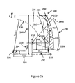
- FIG. 2 a illustrates a set of key structural constraints for the design of the present invention in a cross-sectional view in the YZ plane.
- FIG. 2 b illustrates additional structural constraints for the design of the present invention in a cross-sectional view in the XZ plane.
- FIG. 3 illustrates the reference surface 230 in a 3D view.
- FIG. 4 shows a 5-reflection preferred embodiment of the waveguide prism of the present invention with the inner surface approximating an 8-base curve wraparound appearance.
- FIG. 5 shows another 5-reflection preferred embodiment of the waveguide prism of the present invention with the inner surface approximating an 8-base curve wraparound appearance.
- FIG. 6 shows another 5-reflection preferred embodiment of the waveguide prism of the present invention with a flat inner curve on the temple side.
- FIG. 7 shows another 5-reflection preferred embodiment of the waveguide prism of the present invention with a form similar to the previous embodiment in FIG. 6 .
- FIG. 8 shows another 5-reflection preferred embodiment of the waveguide prism of the present invention with the inner surface approximating an 8-base curve wraparound appearance and the embodiment is based on a reflective type micro-display.
- FIG. 9 shows another preferred embodiment of the present invention similar to the previous embodiment in FIG. 8 but with the inner surface approximating a 4-base curve.
- FIG. 10 shows a 3-reflection preferred embodiment of the waveguide prism of the present invention with the inner surface approximating an 8-base curve wraparound appearance.
- FIG. 11 shows the notation and element definition for the embodiment 5 shown in FIG. 8 .
- FIG. 12 shows the MTF plots of the selected fields for Red (625 nm), Green (525 nm), and Blue (465 nm) wavelengths for the embodiment 5.
- FIG. 13 shows the notation and element definition for the embodiment 6 shown in FIG. 9 .
- FIG. 14 shows the MTF plots of the selected fields for Red (625 nm), Green (525 nm), and Blue (465 nm) wavelengths for the embodiment 6.
- FIG. 15 shows a ray tracing example of the see-through path for embodiment 6.
- FIG. 16 shows an illustrative OST-HMD design with a 4-base curve appearance according to the embodiment 6 of the present invention.
- FIG. 17 shows the notation and element definition for the embodiment 7 shown in FIG. 10 .
- FIG. 18 shows the MTF plots of the selected fields for Red (625 nm), Green (525 nm), and Blue (465 nm) wavelengths for the embodiment 7.
- FIG. 19 shows the notation and element definition of the compensation lens for the embodiment 7 shown in FIG. 10 .
- FIG. 20 shows a ray tracing example of the see-through path for the embodiment 7 shown in FIG. 10 .
- FIG. 21 shows Polychromatic MTF plots of selected fields for the see-through path for the embodiment 7 shown in FIG. 10 .
- FIG. 22 shows an untrimmed 3D model of the embodiment 7 of the present invention.
- FIG. 23 shows an illustrative OST-HMD design with an 8-base curve wraparound appearance according to the embodiment 7 of the present invention.
- FIG. 24 shows the mathematical equations that define the shape of the freeform surfaces.
- FIG. 25 shows the parameters of the surfaces for Embodiment 5 of the waveguide shown in FIG. 8 and FIG. 11 .
- FIG. 26 shows the surface parameters for coupling lens and field lens of Embodiment 5 shown in FIG. 8 and FIG. 11 .
- FIG. 27 shows position and orientation parameters of the optical surfaces in Embodiment 5 shown in FIG. 8 and FIG. 11 .
- FIG. 28 shows surface parameters for waveguide prism of Embodiment 6 shown in FIG. 9 and FIG. 13 .
- FIG. 29 shows surface parameters for coupling lens and field lens of Embodiment 6 shown in FIG. 9 and FIG. 13 .
- FIG. 30 shows position and orientation parameters of the optical surfaces in Embodiment 6 shown in FIG. 9 and FIG. 13 .
- FIG. 31 shows surface parameters for waveguide prism of Embodiment 7 shown in FIG. 10 .
- FIG. 32 shows surface parameters for coupling lens and field lens of Embodiment 7 shown in FIG. 10 and FIG. 17 .
- FIG. 33 shows position and orientation parameters of the optical surfaces in Embodiment 7 shown in FIG. 10 and FIG. 17 .
- FIG. 34 shows surface parameters for compensation lens of Embodiment 7 shown in FIG. 10 and FIG. 19 .
- FIG. 35 shows position and orientation parameters of the compensation lens of Embodiment 7 shown in FIG. 10 and FIG. 19 .
- the present invention relates to ergonomically designed freeform optical systems for use as an optical viewing device in optical see-through HMDs with an eyeglass-form appearance and a wide see-through field of view (FOV).
- a typical embodiment of the invention, shown in FIG. 1 is an image display system which projects displayed virtual image into the user's eye pupil through a freeform waveguide prism, allowing the user to see displayed content overlaid upon the real world scene, comprising:
- One aspect of the invention is an ergonomically shaped freeform waveguide prism, which enables an image to be projected into one refractive input surface of the prism, which is then reflected and refracted until it reaches the user's eye.
- the shape, optical path length, and thickness of the waveguide prism are deliberately optimized, enabling a wrapped-around design of optical see-through HMDs that offer ergonomic fit with the human head and attractive eyeglass-like appearance.
- the freeform waveguide prism of the invention comprises at least three physical surfaces each of which contains a plurality of reflective and refractive optical surfaces disposed upon the physical surfaces, where the interior space of the physical surfaces is filled by a refractive medium having an index (n) greater than 1, the physical and optical surfaces comprising:
- the inner surface 115 and the outer surface 125 of the waveguide is appropriately designed to produce a plurality of reflections that guide light towards the user's pupil without distorting the image.
- the plurality of reflections extends the optical path length so that the width of the waveguide prism closely fit with the width of an average human head.
- the long optical path length enables the design of the waveguide prism into an ergonomic shape.
- the long optical path of the prism further allows moving the image display unit 105 to the side of the display frame which reduces the front weight of the HMD system and improves the ergonomic fit of the system.
- the inner surface 115 is constrained to approximate a pre-designated curved surface for the desired eyeglass form factor.
- the outer surface 125 is further constrained to achieve a thin profile with a thickness of typically no more than 30 mm between the inner surface and outer surfaces. In one practice of the art, we constrained the overall thickness between the inner and outer surfaces to be no more than 12 mm.
- the parameters of the inner surface and the outer surface of the waveguide are hence optimized that the image to be projected has minimal distortion at the exit point of the waveguide.
- the inner surface 115 of the waveguide 100 may contain multiple surface segments; each surface segment is described by one unique set of parameters.
- the outer surface 125 of the waveguide 100 may contain multiple surface segments; each surface segment is described by one unique set of parameters.
- a coupling lens 110 may be added between the miniature image display unit 105 and the first refractive surface 130 of the waveguide 100 , facilitating transmission of the light from the display unit 105 into the waveguide.
- the coupling lens may be used to correct for optical aberrations of the waveguide.
- One other aspect of the invention is a freeform see-through compensation lens 160 physically attached to the waveguide prism 100 .
- the compensation lens 160 is designed to counteract the ray shift and distortion caused by the waveguide prism 100 and enables a clear see-through view of a real-world scene across a wide field of view.
- the freeform compensation lens 160 of the invention comprises multiple (typically 2 or more) freeform refractive surfaces, where the interior space of the refractive surfaces is filled by a refractive medium having an index (n) greater than 1, the optical surfaces comprising:
- the compensation lens 160 and the waveguide prism 100 are deliberately optimized together to enable proper viewing of the surrounding environment across a very wide field of view 190 .
- the inner surface 165 and outer surface 170 of the compensation lens 160 are optimized to minimize the shift and distortion introduced to the rays from a real-world scene when the compensation lens 160 is combined with the waveguide prism 100 .
- the inner surface 165 of the compensation lens 160 could be an exact duplicate of the outer surface 125 of the waveguide prism 100 with a small off-set along the z axis.
- the waveguide prism 100 If a reflection on the attached outer surface 125 of the waveguide prism 100 satisfies the TIR condition in the virtual image display path, it is necessary to maintain a small air gap 195 between the waveguide prism 100 and the compensation lens 160 .
- Index matching glue can fill in the air gap 195 to cement the compensation lens 160 with the waveguide prism 100 if there is no TIR requirement on the outer surface 125 of the waveguide prism 100 .
- the inner surface 165 of the compensation lens 160 can also be redesigned along with the outer surface 170 of the compensation lens 160 for better see-through performance.
- the gap 195 between the waveguide prism 100 and the compensation 160 may be constrained to be less than 6 mm at any points along the surfaces.
- the outer surface 170 is further constrained to limit the overall thickness of the waveguide prism 100 and the compensation lens 160 to be typically no more than 30 mm. In one practice of the art, we constrained the overall thickness of the prism and lens to be no more than 15 mm. Both the inner surface 165 and the outer surface 170 of the compensation lens 160 should be sufficiently large for the designated see-through FOV 190 .
- the shape and the thickness of the compensation lens are deliberately optimized, enabling a wrapped-around design of optical see-through HMDs that offer ergonomic fit with the human head and attractive eyeglass-like appearance.
- the inner and outer surfaces on the compensation lens 160 and waveguide prism 100 are sufficiently large to enable a wide see-through field of view 190 as large as the visual field of the human eye, for example, relative to the center of the field of view, up to 90° on the temple side and 60° on the nasal side in the horizontal direction, and up to 60° superiorly and inferiorly in the vertical direction.
- the freeform surfaces on the waveguide prism 100 and compensation lens 160 are optimized to correct ray shifts and distortions to ensure high see-through performance across a large FOV.
- All the above mentioned surfaces are free-form surfaces, including, but not limited to, spherical, aspheric, anamorphic aspheric, XYP polynomial or any other types of mathematical prescriptions, which is asymmetric in YZ plane of the global coordinate as shown in FIG. 1 , where the origin of the coordinate system is located at the center of the exit pupil 150 with Z axis 175 pointing to the external scene, Y axis 180 pointing to the temple side, and X axis 185 pointing vertically along the head.
- the same coordinate system is used for all the drawings and the descriptions.
- the primary goal of the present invention is to design freeform optical systems for use as an optical viewing device in optical see-through HMDs, achieving an eyeglass-form appearance and a wide see-through field of view (FOV).
- designing the waveguide prism requires optimizing the parameters of each individual surface to minimize proper optical error function, for example, wavefront error or system modulation transfer functions (MTF).
- MTF system modulation transfer functions
- the waveguide prism presented in FIG. 1 contains multiple freeform surfaces which offer more design freedom than that of the traditional rotationally symmetric optical surfaces. Therefore, the freeform design approach provides the capability of designing optical viewing devices with better optical performance and ergonomic fit while using fewer surfaces compared with optical viewing devices of the similar specifications that use the traditional rotationally symmetric optical surfaces.
- proper constraints must be applied on all of the surfaces in order to have a valid design of the waveguide prism, to achieve our primary goal of maintaining a desired form factor and providing a large see-through FOV.
- FIGS. 2 and 3 illustrate the structural constraints we employed during our design process. These control methods put structural signature into our design.
- FIG. 2 illustrates a set of key structural constraints for the waveguide prism design.
- FIGS. 2 a and 2 b illustrate a cross-sectional view in the YZ plane and XZ plane, respectively.
- the exit pupil 250 of the waveguide 200 is aligned with the pupil of the human eye;
- the dash line 230 is a reference surface used for constraining the shape of the inner surface 215 of the waveguide 200 , as well as the position of the miniature image display unit 205 .
- the reference surface 230 is a cylindrical surface in 3D space (as shown in FIG. 3 ) approximating the natural curvature of the human head from nasal side of the face to the ear side.
- the radius of the reference surface 230 in the horizontal YZ plane may vary from 40 mm to as large as 100 mm, depending on the head size of the targeted user population.
- the radius of the reference surface 230 in the vertical XZ plane may be straight or curved, as long as the inner surface of the prism does not interfere with the face of the user. In one practice of the art, we choose the radius of 65 mm in the horizontal direction which is similar to the radius of an 8-base curve eyeglass.
- the center of the reference curve 232 is defined by the reference dimensions Y ref1 234 , Z ref1 236 and Y HIPD 238 , where the dimension Y HIPD 238 is half of the user's inter-pupillary distance (IPD) and IPD has a typical range of 40 mm to 80 mm for over 95% of the population.
- the reference dimensions 234 , 236 , and 238 are chosen according to specific design goals. In one practice of the art, the dimensions 234 , 236 and 238 are chosen to be 10 mm, 50 mm and 32 mm, respectively, for the example of 8-base curve and an IPD of 64 mm.
- the dash line 240 is another reference surface for constraining the shape of the inner surface 215 .
- the reference surface 240 which may be a planar surface or a curved surface of a desired shape, ensures that the compensation lens 260 does not stick away too much from the user's face, which could result in an optical design with a very poor appearance.
- the dash line 290 a and 290 b mark the boundary of the designated see-through FOV 290 in the horizontal dimension from temple to nose, while the dash line 290 c and 290 d mark the boundary of the designated see-through FOV 290 in the vertical dimension.
- the outer surface 225 of the waveguide prism 200 has much more freedom than the inner surface 215 .
- the outer surface can be broken into multiple surface segments as needed.
- the broken points could lie inside or outside the see-through FOV 290 .
- When the broken point is inside the see-through FOV 290 it is required that there is a at least 1 mm ray-free gap around the intersection line of the two adjacent surface segments to ensure a smooth transition between two segments.
- the outer surface 225 must be wide enough along both X- and Y directions for the designated see-through FOV 290 .
- the maximum distance between the outer surface 225 and the inner surface 216 is constrained, typically less than 30 mm to ensure that the waveguide prism is not too thick.
- the maximum distance we constrained the maximum distance to be less than 15 mm.
- the TIR condition for the reflections on the outer surface 225 is not required.
- a half-mirror coating is required for the surface segment inside the see-through FOV 290 if the TIR condition is not satisfied.
- a high-reflection mirror coating is recommended if the TIR condition is not satisfied.
- the width 244 of the waveguide prism 200 is constrained with a lower bound so that the waveguide prism is wide enough to provide the desired see-through FOV 290 on the temple side.
- the width 244 is further constrained with an upper bound to ensure the resultant waveguide prism does not stick out too much on the temple side of the human head for the purpose of ergonomic fit and attractive appearance.
- the width 244 is set with an upper bound of 50 mm from the exit pupil 250 in Y direction.
- the width 246 of the waveguide prism measured from the eye pupil 250 to the nose side in Y direction, is constrained with a lower bound so that the waveguide prism 200 is wide enough to provide the desired see-through FOV 290 on the nasal side.
- the width 246 is further constrained with an upper bound to ensure the resultant waveguide prism does not interfere with the nose bridge of the human head.
- the width 246 is set with an upper bound of 30 mm from the pupil 250 in Y direction.
- the heights 252 and 254 of the waveguide prism are constrained with a tower bound so that the waveguide prism 200 is tall enough to provide the desired see-through FOV 290 above and below in the vertical dimension.
- Two position constraints are applied to the miniature image display unit 205 : (1) Any part of the display unit should lie outside of the reference surface 230 ; (2) The display unit should not be too far away from the exit pupil 250 in Y direction.
- the compensation lens 260 is designed to counteract the ray shift and distortion caused by the waveguide prism 200 and is physically attached to the waveguide prism 200 .
- the inner surface 265 and outer surface 270 of the compensation lens 260 are optimized to minimize the shift and distortion introduced to the rays from a real-world scene when the compensation lens 260 is combined with the waveguide prism 200 .
- the inner surface 265 of the compensation lens 260 could be an exact duplicate of the outer surface 225 of the waveguide prism 200 with a small off-set along the z axis.
- the waveguide prism 200 If a reflection on the attached outer surface 225 of the waveguide prism 200 satisfies the TIR condition in the virtual image display path, it is necessary to maintain a small air gap 295 between the waveguide prism 200 and the compensation lens 260 .
- Index matching glue can fill in the air gap 295 to cement the compensation lens with the waveguide prism if there is no TIR requirement on the outer surface 225 of the waveguide prism 200 .
- the inner surface 265 of the compensation lens 260 can also be redesigned along with the outer surface 270 of the compensation lens 260 for better see-through performance. For this case, the gap 295 between the waveguide prism 200 and the compensation 260 may be constrained to be less than 6 mm at any points along the surfaces.
- the outer surface is further constrained to limit the overall thickness of the waveguide prism 200 and the compensation lens 260 to be typically no more than 30 mm. In one practice of the art, we constrained the overall thickness of the prism and lens to be no more than 15 mm. Both the inner surface 265 and the outer surface 270 of the compensation lens 260 should be sufficient large for a designated see-through FOV 290 .
- FIG. 3 illustrates the reference surface 230 in a 3D view.
- the reference curve 230 in FIG. 2 is swept along X axis to a cylindrical surface 330 .
- the entire inner surface 325 of the waveguide prism 300 should lie outside the cylindrical surface 330 to ensure the prism will not physically interfere with the users face.
- the circle 350 marks the exit pupil position of the waveguide 300 .
- FIG. 4 shows a 5-reflection preferred embodiment of the waveguide prism of the present invention with the inner surface approximating an 8-base curve wraparound appearance.
- This embodiment can be used to implement an HMD system with an 8-base wraparound eyeglass form factor.
- the inner physical surface 415 and the outer physical surface 425 of the waveguide prism 400 are two continuous, smooth surfaces, each of which are described by a set of freeform surface parameters.
- the refractive surface 430 of the waveguide prism 400 is not a part of the inner surface 415 and is described by a different set of surface parameters.
- the ray bundles 440 a , 440 b and 440 c are originated from three different pixels on the miniature image display unit 405 .
- a coupling lens 410 is used to help correct optical aberrations and improve the image quality.
- the ray bundles 440 a , 440 b and 440 c enter the waveguide prism 400 through the refractive surface 430 , are reflected consecutively five times (R 1 through R 5 ) by the outer surface 425 and the inner surface 415 , are then transmitted through the refractive surface 435 , and reach the exit pupil 450 .
- the reflection R 1 on the outer surface 425 and the reflection R 2 on the inner surface 415 satisfy the TIR condition, while the reflection R 4 on the inner surfaces 415 and the reflections R 3 and R 5 on the outer surface 425 do not satisfy the TIR condition.
- a dielectric coating is preferred.
- the inner surface 415 is constrained to approximate a pre-defined 8-base curve in the horizontal dimension.
- the ray bundles 440 a , 440 b and 440 c are refocused and form intermediate images 455 a , 455 b and 455 c , respectively.
- FIG. 5 shows another 5-reflection preferred embodiment of the waveguide prism of the present invention with the inner surface approximating an 8-base curve.
- the inner physical surface 515 of the waveguide prism 500 is broken into two surface segments 515 a and 515 b , each of which is a smooth surface described by a different set of freeform surface parameters.
- the outer physical surface 525 of the waveguide prism 500 is a continuous, smooth surface described by a set of freeform surface parameters.
- the refractive surface 630 and the reflective surface 515 a are described by the same set of freeform surface parameters and thus are one single smooth surface; the reflective surface 515 b and the refractive surface 535 are described by the same set of freeform surface parameters and are one single smooth surface.
- the surface segments 515 a and 515 b are connected by a surface segment 615 c .
- the surface segment 516 c is designed to maintain the first-order continuity at the intersection between surfaces 515 b and 515 c if the intersection is inside the upper boundary 590 a of the see-through FOV 590 .
- the first-order continuity at the intersection between surfaces 515 a and 516 c may also be necessary if the intersection is inside the upper boundary 690 a of the see-through FOV 590 .
- the reflections R 2 , R 3 and R 4 satisfy the TIR condition, while the reflections R 1 and R 5 do not satisfy the TIR condition.
- the outer surface 525 is coated with a semi-transparent coating.
- a dielectric coating is preferred.
- a mirror coating can be applied on the upper surface segment 525 a if the segment 625 a is outside the upper boundary 690 a of the see-through FOV 590 .
- a coupling lens 510 is used to help correct optical aberrations and improve the image quality.
- the surface segment 515 b is constrained to approximate an 8-base curve, while the surface segment 515 a is constrained to move closer to the outer surface 525 for the benefit of reducing the overall weight of the waveguide prism 500 .
- FIG. 6 shows another 5-reflection preferred embodiment of the waveguide prism of the present invention with a flat inner curve on the temple side.
- the refractive surface 630 of the waveguide prism 600 is not a part of the inner surface 615 and is described by a different set of surface parameters, while the inner surface 615 is a continuous, smooth surface.
- the refractive surface 635 shares the same set of surface parameters as the surface 615 .
- the outer physical surface 625 of the waveguide prism 600 is a continuous, smooth surface described by a set of freeform surface parameters.
- the reflections R 2 , R 3 , and R 4 satisfy the TIR condition, while the reflections R 1 and R 5 do not satisfy the TIR condition.
- the outer surface 625 is coated with a semi-transparent coating.
- a dielectric coating is preferred.
- a mirror coating can be applied on the upper surface segment 625 a if the surface segment 625 a is outside the upper boundary 690 a of the see-through FOY 690 .
- the inner surface 615 is not constrained to any predefined curvature but the position of the surface is constrained to ensure the prism is not too far away from the human face.
- a coupling lens 610 is used to help correct optical aberrations and improve the image quality.
- FIG. 7 shows another 5-reflection preferred embodiment of the waveguide prism of the present invention similar to the embodiment shown in FIG. 6 .
- the refractive surface 730 of the waveguide prism 700 is not a part of the inner surface 715 and is described by a different set of surface parameters, while the inner surface 715 is a continuous, smooth surface.
- the refractive surface 735 shares the same set of surface parameters as the surface 715 .
- the outer physical surface 725 of the waveguide prism 700 is broken into two segments 725 a and 725 b , each of which is a smooth surface described by a different set of freeform surface parameters.
- the surface segments 725 a and 725 b are connected by a surface segment 725 c .
- the surface segment 725 c is designed to maintain the first-order continuity at the intersection between surfaces 725 b and 725 c if the intersection is inside the upper boundary 790 a of the see-through FOV 790 .
- the first-order continuity at the intersection between surfaces 725 a and 725 c may also be necessary if the intersection is inside the upper boundary 790 a of the see-through FOV 790 .
- this embodiment does not require a coupling lens between the waveguide prism 700 and the miniature image display unit 705 as the prism itself is sufficient to correct optical aberrations.
- FIG. 8 shows a 5-reflection preferred embodiment of the waveguide prism of the present invention with the inner surface approximating an 8-base curve, and this embodiment is designed specifically for a reflective-type illuminated pixel arrays such as LCoS or FLCoS type micro-display panels.
- the inner physical surface 815 of the waveguide prism 800 is broken into two surface segments 815 a and 815 b , each of which is a smooth surface described by a different set of freeform surface parameters.
- the refractive surface 830 and the reflective surface 815 a are one single smooth surface and are described by the same set of surface parameters; the reflective surfaces 815 b and the refractive surface 835 are one single smooth surface and are described by the same set of surface parameters.
- the surface segments 815 a and 815 b are connected by a surface segment 815 c .
- the surface segment 815 c is designed to maintain the first-order continuity at the intersection between surfaces 815 b and 815 c if the intersection is inside the upper boundary 890 a of the see-through FOV 890 .
- the first-order continuity at the intersection between surfaces 815 a and 815 c may also be necessary if the intersection is inside the upper boundary 890 a of the see-through FOV 890 .
- the outer physical surface 825 of the waveguide prism 800 is broken into two segments 825 a and 825 b , each of which is a smooth surface described by a different set of freeform surface parameters.
- the surface segments 825 a and 825 b are connected by a surface segment 825 c .
- the surface segment 825 c is designed to maintain the first-order continuity at the intersection between surfaces 825 b and 825 c if the intersection is inside the upper boundary 890 a of the see-through FOV 890 .
- the first-order continuity at the intersection between surfaces 825 a and 825 C may also be necessary if the intersection is inside the upper boundary 890 a of the see-through FOV 890 .
- the surface segment 815 b is constrained to approximate an 8-base curve, while the surface segment 816 a is constrained to be closer to the outer surface 825 a for the benefit of reducing the overall weight of the prism.
- the reflections R 2 , R 3 and R 4 satisfy the TIR condition, while the reflections. R 1 and R 5 do not satisfy the TIR condition. Therefore, a semi-transparent coating is required for the outer surface 825 in order to increase the reflection efficiency. In order to maintain the TIR condition for the reflection R 3 on the surface 825 b , a dielectric coating is preferred. A mirror coating can be applied on the upper surface segment 825 a if the surface segment 825 a is outside the upper boundary 890 a of the see-through FOV 890 . Between the miniature image display unit 806 and the refractive surface 830 of the waveguide prism 800 , a coupling lens 810 is used to help correct optical aberrations and improve image qualities.
- the miniature image display unit 805 contains a reflective micro-display panel 805 a (e.g. LCoS display panel), a field lens 805 b and a polarized beamsplitter 805 c .
- the field lens 805 b is employed to enforce the tele-centricity of light at the micro-display surface.
- the polarized beamsplitter 805 c acts as a beam combiner to merge the display illumination path (not shown) and the display imaging path.
- the polarized beamsplitter 805 c also acts as a polarizer and then an analyzer for the incoming and outgoing light to micro-display panel 805 a . Element definitions for this embodiment are shown in FIG. 11 , and parameters are given in FIG. 25-27 (Table 2-4).
- FIG. 9 shows another preferred embodiment of the present invention similar to the embodiment shown in FIG. 8 except that the inner physical surface 915 of the waveguide prism 900 is optimized to approximate a 4-base curve instead of an 8-base curve.
- the waveguide prism 900 has the similar structural characteristics to these of the embodiment in FIG. 8 .
- the inner surface segment 915 b is constrained to approximate a 4-base curve.
- this embodiment can be used to implement an HMD system with a 4-base eyeglass form factor, having a flat appearance like a pair of 4-base curve eyeglass.
- this embodiment is designed specifically for a reflective-type illuminated pixel arrays such as LCoS or FLCoS type micro-display panels. Element definitions for this embodiment are shown in FIG. 13 , and parameters are given in FIG. 28-30 (Table 5-7).
- FIG. 10 shows a 3-reflection preferred embodiment of the waveguide prism of the present invention with the inner surface approximating an 8-base curve wraparound appearance.
- This embodiment can be used to implement an HMD system with an 8-base curve wraparound form factor.
- the inner physical surface 1015 and the outer physical surface 1025 of the waveguide prism 1000 are two continuous, smooth surfaces, each of which are described by a set of freeform surface parameters.
- the refractive surface 1030 of the waveguide prism 1000 is not a part of the inner surface 1015 and is described by a different set of surface parameters.
- the miniature image display unit 1005 contains a micro-display panel 1006 a and a field lens 1005 b which is used to achieve tele-centricity of light at the micro-display surface.
- the micro-display panel 1006 a can be either a reflective type micro-display (for example: LCoS, FLCoS, or DMD panels) or a transmissive type micro-display (for example: LCD panel) or a self-emissive type micro-display (for example: OLED panel).
- a beamsplitter (not shown) is required after the field lens 1005 b to introduce an illumination path (not shown).
- a coupling lens 1010 is used to help correct optical aberrations and improve image qualities.
- the ray bundles 1040 a , 1040 b and 1040 c originated from three different pixels on the micro-display 1005 a enter the waveguide prism 1000 through the refractive surface 1030 , are reflected three times by the inner surfaces 1015 and the outer surface 1025 , are then transmitted through the refractive surface 1035 , and reach the exit pupil 1050 .
- the reflections R 1 and R 2 satisfy the TIR condition and the reflection R 3 on the outer surface 1025 does not satisfy the TIR condition.
- the inner surface 1015 is constrained to approximate a pre-defined 8-base curve.
- the ray bundles 1040 a , 1040 b and 1040 c are refocused and form intermediate images 1055 a , 1055 b and 1055 c , respectively. Element definitions for this embodiment are shown in FIG. 17 , and parameters are given in FIG. 31-33 (Table 8-10).
- the image display unit may be disposed towards the inner surface, outer surface, or edge surface, depending on the shape of the lens, the number of reflections and the desired eyeglass form factor.
- the image display apparatus would usually be disposed towards the edge surface of the waveguide, while for a 4-base eyeglass form factor it would usually be disposed towards the inner surface.
- a feature of the present invention is that the extended optical path length requires the surfaces to be designed such that ray bundles are refocused at intermediate points through the prism. This refocusing of the light produces an intermediate image part way through the prism, as a result the rays have diverged less at the exit refractive surface, an advantage of which is the overall thickness of the waveguide does not increase rapidly as the field of view of the virtual image path increases in an OST-HMD.
- FIGS. 4 ⁇ 10 Seven embodiments ( FIGS. 4 ⁇ 10 ) are presented according to the present invention.
- numerical data of embodiments 5 to 7 FIG. 8 ⁇ 10 ) are presented.
- Three types of freeform surfaces are employed in the embodiments and the mathematic equation of each surface type is listed in FIG. 24 (Table 1).
- the equations in FIG. 24 (Table 1) are given in the local coordinate system with the origin at the vertex of the surface.
- the position and orientation of the surface are either directly defined in the global coordinate system or through a reference coordinate system.
- the global coordinate is located at the center of the exit pupil with the x axis pointing inside the paper, y axis pointing up and z axis pointing right toward the external scene.
- FIG. 11 shows the notation and element definition for embodiment 5 ( FIG. 8 ).
- the embodiment is designed for a 0.37′′ reflective-type display (for instance LCoS or FLCoS), yielding a virtual. FOV of 26.5° in Y direction and 15° in X direction, and 30° diagonally.
- the system F/number is 2.
- FIG. 25 (Table 2) lists the surface parameters for the waveguide prism 800 and
- FIG. 26 (Table 3) lists the surface parameters for the coupling lens 810 and field lens 805 b .
- the position and orientation of all the optical surfaces as well as the optical material for each optical element are listed in FIG. 27 (Table 4).
- the MTF plots of selected fields for Red (625 nm), Green (525 nm), and Blue (465 nm) wavelengths are shown in FIG. 12 .
- the MTF performance was evaluated for a centered 3-mm pupil at a cutoff spatial frequency of 80 cycles/mm, which corresponds to an equivalent pixel size of 6.25 ⁇ m.
- FIG. 13 shows the notation and element definition for embodiment 6 ( FIG. 9 ).
- the embodiment is designed for a 0.37′′ reflective-type display (for instance LCoS or FLCoS), yielding a virtual FOV of 26.5° in Y direction and 15° in X direction, and 30° diagonally.
- the system F/number is 2.
- FIG. 28 (Table 5) lists the surface parameters for the waveguide prism 900 and
- FIG. 29 (Table 6) lists the surface parameters for the coupling lens 910 and field lens 905 b .
- the position and orientation of all the optical surfaces as well as the optical material for each optical element are listed in FIG. 30 (Table 7).
- the MTF plots of selected fields for Red (625 nm), Green (525 nm), and Blue (465 nm) wavelengths are shown in FIG. 14 .
- the MTF performance was evaluated for a centered 3-mm pupil at a cutoff spatial frequency of 80 cycles/mm, which corresponds to an equivalent pixel size of 6.25 ⁇ m.
- FIG. 15 shows a ray-tracing example of the see-through path for the embodiment 6.
- the overall corrected see-through FOV is 75° in the horizontal direction and 70° in the vertical direction.
- FIG. 16 shows an illustrative OST-HMD design with a 4-base curve appearance according to the embodiment 6 of the present invention.
- the OST-HMD device contains a pair of optical assembly of the embodiment 6, a frame 1602 , and an electronics unit 1604 .
- Each optical assembly contains the freeform waveguide prism 1600 , compensation lens 1660 , coupling lens 1610 , beam splitter 1605 c , field lens 1605 b , and a micro-display panel 1605 a .
- the electronics unit 1604 inside the two arms of the frame 1602 can be used to integrate the necessary electronics, which include but not limited to, circuit boards for the micro-display unit and display illumination unit, image and video receiving and processing unit, audio input and output unit, graphic processing unit, positioning unit, wireless communication unit, and computing processing unit, etc.
- the designated see-through FOV 1690 of this embodiment is 45° on temple side and 30° on nasal side in the horizontal dimension and ⁇ 35° in the vertical dimension (not shown).
- FIG. 17 shows the notation and element definition for embodiment 7 ( FIG. 10 ).
- the embodiment is designed for a 0.37′′ reflective-type display (for instance LCoS or FLCoS), yielding a virtual FOV of 26.5° in Y direction and 15° in X direction, and 30° diagonally.
- the system F/number is 2.
- FIG. 31 (Table 8) lists the surface parameters for the waveguide prism 1000 and
- FIG. 32 (Table 9) lists the surface parameters for the coupling lens 1010 and field lens 1005 b .
- the position and orientation of all the optical surfaces as well as the optical material for each optical element are listed in FIG. 33 (Table 10).
- the MTF plots of selected fields for Red (625 nm), Green (525 nm), and Blue (465 nm) wavelengths are shown in FIG. 18 .
- the MTF performance was evaluated for a centered 3-mm pupil at a cutoff spatial frequency of 80 cycles/mm, which corresponds to an equivalent pixel size of 6.25 ⁇ m.
- FIG. 19 shows the notation and element definition for the compensation lens of embodiment 7 ( FIG. 10 ).
- FIG. 20 shows a ray-tracing example of the see-through path for the embodiment 6.
- the overall corrected see-through FOV is 80° in the horizontal direction and 70° in the vertical direction.
- the polychromatic MTF plots of the selected fields for the see-through path are shown in FIG. 21 .
- the MTF performance was evaluated for a centered 3-mm pupil at a cutoff spatial frequency of 60 cycles/mm.
- FIG. 22 shows an untrimmed 3D model of the embodiment 7.
- the model contains the waveguide prism, compensation lens, coupling lens, and field lens.
- the model also includes a beam splitter space to provide room for inserting a beam splitter to introduce an illumination path for a reflective-type micro-display.
- the model further includes a cover glass for the micro-display.
- FIG. 23 shows an illustrative OST-HMD design with an 8-base curve appearance according to the embodiment 7 of the present invention.
- the OST-HMD device contains a pair of optical assembly of the embodiment 7, a frame 2302 , and an electronics unit 2304 .
- Each optical assembly contains the freeform waveguide prism 2300 , compensation lens 2360 , coupling lens 2310 , field lens 2305 b , and a micro-display panel 2305 a .
- the electronics unit 2304 inside the two arms of the frame 2302 can be used to integrate the necessary electronics, which include but not limited to, circuit boards for the micro-display unit and display illumination unit, image and video receiving and processing unit, audio input and output unit, graphic processing unit, positioning unit, wireless communication unit, and computing processing unit, etc.
- the designated see-through FOV 2390 of this embodiment is 65° on temple side and 35° on nasal side in the horizontal dimension and ⁇ 35° in the vertical dimension (not shown).
Abstract
Description
-
- a. A miniature
image display unit 105, which serves as an image source and projects light into the waveguide; - b. an optional
coupling lens group 110, composed of one or more lenses that guide light from the display unit into thefreeform waveguide prism 100 and correct for optical aberrations; - c. a transparent freeform
optical waveguide prism 100, as described, which accepts the light from thedisplay unit 105 and propagates the light until the image is projected into the user's eye pupil; where the waveguide allows the light from a real-world scene to pass through and enters the user's eye pupil; where the waveguide has a physicalinner surface 115,physical edge surface 120 and physicalouter surface 125, a firstrefractive surface 130, and a secondrefractive surface 135, and a plurality of reflective surfaces; - d. a
freeform compensation lens 160, secured to the physicalouter surface 125 of the waveguide, which corrects for optical distortion caused by viewing the world through the waveguide prism; where the innerphysical surface 165 of thecompensation lens 160 approximates the shape of the outerphysical surface 125 of thewaveguide prism 100, and asmall gap 195 is maintained between thewaveguide 100 and thecompensation lens 160 on surfaces where the TIR criterion is satisfied for the outerphysical surface 125 of the waveguide; where thecompensation lens 160 is designed to compensate for the effect of ray shift and distortion caused by thewaveguide 100 so that the user maintains a clear see-through field ofview 190;
whereupon theimage display unit 105 can be any type of self-emissive or illuminated pixel arrays that can serve as an image source, including, but not limited to, a liquid crystal on silicon (LCoS) display device, a liquid crystal display (LCD) panel, an organic light emitting display (OLED), ferroelectric liquid crystal on silicon (LCoS device, digital mirror device (DMD), or a micro-projector built upon these aforementioned or other types of micro-display devices;
Whereupon theimage display unit 105 transmits light 140 into theoptional coupling lens 110 followed by thewaveguide 100 or into the waveguide directly, through a firstrefractive surface 130;
whereupon the light 140 follows apath 145 along the waveguide that comprises a plurality of reflections from the firstrefractive surface 130 to the secondrefractive surface 135;
whereupon the rays of the light 140 following apath 145 along the waveguide may cross and form anintermediate image 155 inside thewaveguide 100;
whereupon light 140 passes through the secondrefractive surface 135 beyond which where the user places his or herpupil 150 to view the image; whereupon light from the real-world scene 198 passes through thecompensation lens 160 and thewaveguide 100 before reaching thepupil 150.
- a. A miniature
-
- a. a physical
inner surface 115, disposed towards the eyeball of the user, where the physical inner surface, containing a plurality of reflective and refractive surfaces appropriate to propagating an image to the eyeball of the user, is constrained to fit the ergonomic factors of the human head; - b. a physical
outer surface 125, disposed towards the external scene, where the physical outer surface contains a plurality of reflective surfaces appropriate to reflecting an image to the eyeball of the user, where the physical outer surface is within typically 30 mm of the inner surface at all points, where the physical outer surface contains at least one refractive surface to allow light from the external scene to pass through the waveguide and reach the eyeball of the user; - c. a
physical edge surface 120, which may potentially contain a refractive surface for light from an image display unit to enter the waveguide; - d. a
refractive input surface 130, disposed on one of the physical surfaces, that allows light from an image display unit to enter the waveguide; - e. a refractive output surface 136 that allows light to exit the waveguide, disposed upon the physical inner surface, near the pupil of the user, where the refractive surface may or may not be covered by a semi-transparent coating;
- f. a plurality of reflective surfaces, disposed upon the physical inner and outer surfaces, where each reflection is produced by either satisfying the TIR condition, or by the application of a semi-transparent, partially reflective coating to the surface of the waveguide.
whereupon light 140 from animage display unit 105 enters the waveguide, through a firstrefractive surface 130;
whereupon the light 140 follows apath 145 along the waveguide that comprises a plurality of reflections upon the plurality of reflective surfaces, from the firstrefractive surface 130 to the secondrefractive surface 135, where each reflection is produced either by satisfying conditions of Total Internal Reflection, or by the application of a semi-transparent coating to the surface;
whereupon light 140 passes through the secondrefractive surface 135 beyond which where the user places his or herpupil 150 to view the image;
whereupon light 198 from the real-world scene, after being refracted by thecompensation lens 160, is refracted through the physicalouter surface 125 of thewaveguide 100 and the physicalinner surface 115 of the waveguide before reaching thepupil 150.
- a. a physical
-
- a. a refractive
outer surface 170, disposed towards the external scene, that allows light 198 from the external scene to enter the compensation lens, where the refractive outer surface is typically a continuous, single refractive surface and is within typically 30 mm of the physicalinner surface 115 of thewaveguide prism 100 at all points; - b. a refractive
inner surface 165, disposed towards theouter surface 125 of thewaveguide prism 100, which allows light to exit the compensation lens and enters into thewaveguide prism 100, where the refractiveinner surface 165, containing a plurality of refractive surfaces, is typically constrained to approximate or match the shape of theouter surface 125 of thewaveguide prism 100,
whereupon light from the real-world scene 198, is refracted through the refractiveouter surface 170 and the refractiveinner surface 165 ofcompensation lens 160, the physicalouter surface 125 and the physicalinner surface 115 of thewaveguide 100 before reaching thepupil 150.
- a. a refractive
-
- a. The entire
inner surface 215 is constrained to lie outside thereference surface 230 to ensure that the prism will not interfere with the user's head; - b. The
inner surface 215 could deviate away from thereference surface 230, but it is constrained to not pass thereference surface 240; - c. When it is necessary to break the
inner surface 215 from a single surface description into multiple surface segments, each of which has its own mathematical formula, to increase the design freedom, the broken point must lie outside theupper boundary 290 a of the see-throughFOV 290, or the broken segments must be adjoined by an intermediate segment by maintaining first order continuity. In other words, the surface segment 215 a of theinner surface 215 inside of the see-throughFOV 290 must be a continuous, smooth optical surface. The local radius curvature of the surface segment 215 a should be no less than 20 mm in order to maintain the see-through distortion at an acceptable level. - d. The surface segment 215 a is constrained to approximate a designed curvature. The shape of the inner surface segment 215 a determines the appearance of the waveguide prism as the
outer surface 270 of thecompensation lens 260 will have a similar shape as the inner surface segment 215 a. In one practice of the art, the surface segment 215 a is designed to follow a base-8 curve positioned 10 mm outside thereference surface 230 to achieve an 8-base wraparound design.
- a. The entire
Claims (27)
Priority Applications (4)
| Application Number | Priority Date | Filing Date | Title |
|---|---|---|---|
| US13/335,884 US9348143B2 (en) | 2010-12-24 | 2011-12-22 | Ergonomic head mounted display device and optical system |
| US14/726,396 US10156722B2 (en) | 2010-12-24 | 2015-05-29 | Methods and systems for displaying stereoscopy with a freeform optical system with addressable focus for virtual and augmented reality |
| US14/991,810 US9753286B2 (en) | 2010-12-24 | 2016-01-08 | Ergonomic head mounted display device and optical system |
| US15/653,287 US20170336639A1 (en) | 2010-12-24 | 2017-07-18 | Ergonomic head mounted display device and optical system |
Applications Claiming Priority (2)
| Application Number | Priority Date | Filing Date | Title |
|---|---|---|---|
| US201061427162P | 2010-12-24 | 2010-12-24 | |
| US13/335,884 US9348143B2 (en) | 2010-12-24 | 2011-12-22 | Ergonomic head mounted display device and optical system |
Related Child Applications (1)
| Application Number | Title | Priority Date | Filing Date |
|---|---|---|---|
| US14/991,810 Division US9753286B2 (en) | 2010-12-24 | 2016-01-08 | Ergonomic head mounted display device and optical system |
Publications (2)
| Publication Number | Publication Date |
|---|---|
| US20120162549A1 US20120162549A1 (en) | 2012-06-28 |
| US9348143B2 true US9348143B2 (en) | 2016-05-24 |
Family
ID=46314494
Family Applications (3)
| Application Number | Title | Priority Date | Filing Date |
|---|---|---|---|
| US13/335,884 Active 2033-09-05 US9348143B2 (en) | 2010-12-24 | 2011-12-22 | Ergonomic head mounted display device and optical system |
| US14/991,810 Active US9753286B2 (en) | 2010-12-24 | 2016-01-08 | Ergonomic head mounted display device and optical system |
| US15/653,287 Abandoned US20170336639A1 (en) | 2010-12-24 | 2017-07-18 | Ergonomic head mounted display device and optical system |
Family Applications After (2)
| Application Number | Title | Priority Date | Filing Date |
|---|---|---|---|
| US14/991,810 Active US9753286B2 (en) | 2010-12-24 | 2016-01-08 | Ergonomic head mounted display device and optical system |
| US15/653,287 Abandoned US20170336639A1 (en) | 2010-12-24 | 2017-07-18 | Ergonomic head mounted display device and optical system |
Country Status (10)
| Country | Link |
|---|---|
| US (3) | US9348143B2 (en) |
| EP (2) | EP4036630A1 (en) |
| JP (5) | JP6185844B2 (en) |
| KR (3) | KR101997845B1 (en) |
| CN (2) | CN107179607B (en) |
| AU (3) | AU2011348122A1 (en) |
| CA (1) | CA2822978C (en) |
| IL (3) | IL255277B (en) |
| NZ (2) | NZ725592A (en) |
| WO (1) | WO2012088478A1 (en) |
Cited By (191)
| Publication number | Priority date | Publication date | Assignee | Title |
|---|---|---|---|---|
| US20170000342A1 (en) | 2015-03-16 | 2017-01-05 | Magic Leap, Inc. | Methods and systems for detecting health conditions by imaging portions of the eye, including the fundus |
| US9857591B2 (en) | 2014-05-30 | 2018-01-02 | Magic Leap, Inc. | Methods and system for creating focal planes in virtual and augmented reality |
| WO2018009467A1 (en) * | 2016-07-05 | 2018-01-11 | Vuzix Corporation | Head mounted imaging apparatus with optical coupling |
| US9904058B2 (en) | 2016-05-12 | 2018-02-27 | Magic Leap, Inc. | Distributed light manipulation over imaging waveguide |
| US10078919B2 (en) | 2016-03-31 | 2018-09-18 | Magic Leap, Inc. | Interactions with 3D virtual objects using poses and multiple-DOF controllers |
| US10089526B2 (en) | 2015-08-21 | 2018-10-02 | Magic Leap, Inc. | Eyelid shape estimation |
| US10089453B2 (en) | 2016-03-07 | 2018-10-02 | Magic Leap, Inc. | Blue light adjustment for biometric identification |
| US10088689B2 (en) * | 2015-03-13 | 2018-10-02 | Microsoft Technology Licensing, Llc | Light engine with lenticular microlenslet arrays |
| US10120194B2 (en) | 2016-01-22 | 2018-11-06 | Corning Incorporated | Wide field personal display |
| US10146997B2 (en) | 2015-08-21 | 2018-12-04 | Magic Leap, Inc. | Eyelid shape estimation using eye pose measurement |
| US10156725B2 (en) | 2014-09-29 | 2018-12-18 | Magic Leap, Inc. | Architectures and methods for outputting different wavelength light out of waveguides |
| US10163011B2 (en) | 2016-06-30 | 2018-12-25 | Magic Leap, Inc. | Estimating pose in 3D space |
| US10163010B2 (en) | 2015-10-16 | 2018-12-25 | Magic Leap, Inc. | Eye pose identification using eye features |
| US10234687B2 (en) | 2014-05-30 | 2019-03-19 | Magic Leap, Inc. | Methods and system for creating focal planes in virtual and augmented reality |
| US10254454B2 (en) | 2015-06-15 | 2019-04-09 | Magic Leap, Inc. | Display system with optical elements for in-coupling multiplexed light streams |
| US10261162B2 (en) | 2016-04-26 | 2019-04-16 | Magic Leap, Inc. | Electromagnetic tracking with augmented reality systems |
| US10260864B2 (en) | 2015-11-04 | 2019-04-16 | Magic Leap, Inc. | Dynamic display calibration based on eye-tracking |
| US10296792B2 (en) | 2016-07-14 | 2019-05-21 | Magic Leap, Inc. | Iris boundary estimation using cornea curvature |
| US10302957B2 (en) | 2016-02-24 | 2019-05-28 | Magic Leap, Inc. | Polarizing beam splitter with low light leakage |
| US10306213B2 (en) | 2016-02-26 | 2019-05-28 | Magic Leap, Inc. | Light output system with reflector and lens for highly spatially uniform light output |
| US10317690B2 (en) | 2014-01-31 | 2019-06-11 | Magic Leap, Inc. | Multi-focal display system and method |
| US10332315B2 (en) | 2016-06-20 | 2019-06-25 | Magic Leap, Inc. | Augmented reality display system for evaluation and modification of neurological conditions, including visual processing and perception conditions |
| US10338400B2 (en) | 2017-07-03 | 2019-07-02 | Holovisions LLC | Augmented reality eyewear with VAPE or wear technology |
| US10337691B2 (en) | 2016-06-10 | 2019-07-02 | Magic Leap, Inc. | Integrating point source for texture projecting bulb |
| US10371896B2 (en) | 2016-12-22 | 2019-08-06 | Magic Leap, Inc. | Color separation in planar waveguides using dichroic filters |
| US10371876B2 (en) | 2017-04-18 | 2019-08-06 | Magic Leap, Inc. | Reflective diffractive gratings with variable reflectivity and display systems having the same |
| US10386636B2 (en) | 2014-01-31 | 2019-08-20 | Magic Leap, Inc. | Multi-focal display system and method |
| US10402649B2 (en) | 2016-08-22 | 2019-09-03 | Magic Leap, Inc. | Augmented reality display device with deep learning sensors |
| US10430985B2 (en) | 2014-03-14 | 2019-10-01 | Magic Leap, Inc. | Augmented reality systems and methods utilizing reflections |
| US10442727B2 (en) | 2017-01-05 | 2019-10-15 | Magic Leap, Inc. | Patterning of high refractive index glasses by plasma etching |
| US10445881B2 (en) | 2016-09-29 | 2019-10-15 | Magic Leap, Inc. | Neural network for eye image segmentation and image quality estimation |
| US10455153B2 (en) | 2017-03-21 | 2019-10-22 | Magic Leap, Inc. | Depth sensing techniques for virtual, augmented, and mixed reality systems |
| US10451895B2 (en) | 2016-07-25 | 2019-10-22 | Magic Leap, Inc. | Light field processor system |
| US10451799B2 (en) | 2017-01-23 | 2019-10-22 | Magic Leap, Inc. | Eyepiece for virtual, augmented, or mixed reality systems |
| US10459231B2 (en) | 2016-04-08 | 2019-10-29 | Magic Leap, Inc. | Augmented reality systems and methods with variable focus lens elements |
| US10466480B2 (en) | 2016-01-07 | 2019-11-05 | Magic Leap, Inc. | Virtual and augmented reality systems and methods having unequal numbers of component color images distributed across depth planes |
| US10466778B2 (en) | 2016-01-19 | 2019-11-05 | Magic Leap, Inc. | Eye image selection |
| US10466394B2 (en) | 2017-01-27 | 2019-11-05 | Magic Leap, Inc. | Diffraction gratings formed by metasurfaces having differently oriented nanobeams |
| US10466561B2 (en) | 2016-12-08 | 2019-11-05 | Magic Leap, Inc. | Diffractive devices based on cholesteric liquid crystal |
| US10466478B2 (en) | 2015-09-23 | 2019-11-05 | Magic Leap, Inc. | Eye imaging with an off-axis imager |
| US10481317B2 (en) | 2016-08-22 | 2019-11-19 | Magic Leap, Inc. | Nanograting method and apparatus |
| US10481399B2 (en) | 2016-09-21 | 2019-11-19 | Magic Leap, Inc. | Systems and methods for optical systems with exit pupil expander |
| US10489680B2 (en) | 2016-10-04 | 2019-11-26 | Magic Leap, Inc. | Efficient data layouts for convolutional neural networks |
| US20190384061A1 (en) * | 2018-06-13 | 2019-12-19 | Futurewei Technologies, Inc. | Achromatic Freeform Prism for Near Eye Displays |
| US10521661B2 (en) | 2017-09-01 | 2019-12-31 | Magic Leap, Inc. | Detailed eye shape model for robust biometric applications |
| US10521025B2 (en) | 2015-10-20 | 2019-12-31 | Magic Leap, Inc. | Selecting virtual objects in a three-dimensional space |
| US10527851B2 (en) | 2016-05-06 | 2020-01-07 | Magic Leap, Inc. | Metasurfaces with asymmetric gratings for redirecting light and methods for fabricating |
| US10531220B2 (en) | 2016-12-05 | 2020-01-07 | Magic Leap, Inc. | Distributed audio capturing techniques for virtual reality (VR), augmented reality (AR), and mixed reality (MR) systems |
| US10536690B2 (en) | 2016-01-29 | 2020-01-14 | Magic Leap, Inc. | Display for three-dimensional image |
| US10534954B2 (en) | 2016-06-03 | 2020-01-14 | Magic Leap, Inc. | Augmented reality identity verification |
| US10534043B2 (en) | 2016-09-26 | 2020-01-14 | Magic Leap, Inc. | Calibration of magnetic and optical sensors in a virtual reality or augmented reality display system |
| US10540941B2 (en) | 2018-01-30 | 2020-01-21 | Magic Leap, Inc. | Eclipse cursor for mixed reality displays |
| US10558047B2 (en) | 2016-09-22 | 2020-02-11 | Magic Leap, Inc. | Augmented reality spectroscopy |
| US10564533B2 (en) | 2017-03-21 | 2020-02-18 | Magic Leap, Inc. | Low-profile beam splitter |
| US10565790B2 (en) | 2016-11-11 | 2020-02-18 | Magic Leap, Inc. | Periocular and audio synthesis of a full face image |
| US10571693B2 (en) | 2016-03-01 | 2020-02-25 | Magic Leap, Inc. | Reflective switching device for inputting different wavelengths of light into waveguides |
| US10573042B2 (en) | 2016-10-05 | 2020-02-25 | Magic Leap, Inc. | Periocular test for mixed reality calibration |
| US10580213B2 (en) | 2016-09-13 | 2020-03-03 | Magic Leap, Inc. | Systems and methods for sign language recognition |
| US10607609B2 (en) | 2016-08-12 | 2020-03-31 | Magic Leap, Inc. | Word flow annotation |
| US10621747B2 (en) | 2016-11-15 | 2020-04-14 | Magic Leap, Inc. | Deep learning system for cuboid detection |
| US10627625B2 (en) | 2016-08-11 | 2020-04-21 | Magic Leap, Inc. | Automatic placement of a virtual object in a three-dimensional space |
| US10649527B2 (en) | 2016-03-04 | 2020-05-12 | Magic Leap, Inc. | Current drain reduction in AR/VR display systems |
| US10657376B2 (en) | 2017-03-17 | 2020-05-19 | Magic Leap, Inc. | Room layout estimation methods and techniques |
| US10671160B2 (en) | 2017-05-31 | 2020-06-02 | Magic Leap, Inc. | Eye tracking calibration techniques |
| US10681489B2 (en) | 2015-09-16 | 2020-06-09 | Magic Leap, Inc. | Head pose mixing of audio files |
| US10698215B2 (en) | 2016-03-25 | 2020-06-30 | Magic Leap, Inc. | Virtual and augmented reality systems and methods |
| US10719951B2 (en) | 2017-09-20 | 2020-07-21 | Magic Leap, Inc. | Personalized neural network for eye tracking |
| US10735649B2 (en) | 2018-02-22 | 2020-08-04 | Magic Leap, Inc. | Virtual and augmented reality systems and methods using display system control information embedded in image data |
| US10746999B2 (en) | 2016-12-28 | 2020-08-18 | Magic Leap, Inc. | Dual depth exit pupil expander |
| US10768693B2 (en) | 2017-04-19 | 2020-09-08 | Magic Leap, Inc. | Multimodal task execution and text editing for a wearable system |
| US10775618B2 (en) | 2018-03-16 | 2020-09-15 | Magic Leap, Inc. | Facial expressions from eye-tracking cameras |
| US10775545B2 (en) | 2016-02-26 | 2020-09-15 | Magic Leap, Inc. | Display system having a plurality of light pipes for a plurality of light emitters |
| US10789753B2 (en) | 2018-04-23 | 2020-09-29 | Magic Leap, Inc. | Avatar facial expression representation in multidimensional space |
| US10813619B2 (en) | 2016-05-09 | 2020-10-27 | Magic Leap, Inc. | Augmented reality systems and methods for user health analysis |
| US10839576B2 (en) | 2017-10-27 | 2020-11-17 | Magic Leap, Inc. | Virtual reticle for augmented reality systems |
| US10838484B2 (en) | 2016-04-21 | 2020-11-17 | Magic Leap, Inc. | Visual aura around field of view |
| US10838210B2 (en) | 2016-07-25 | 2020-11-17 | Magic Leap, Inc. | Imaging modification, display and visualization using augmented and virtual reality eyewear |
| US10852547B2 (en) | 2017-12-15 | 2020-12-01 | Magic Leap, Inc. | Eyepieces for augmented reality display system |
| US10852542B2 (en) | 2017-03-14 | 2020-12-01 | Magic Leap, Inc. | Waveguides with light absorbing films and processes for forming the same |
| US10860070B2 (en) | 2016-11-16 | 2020-12-08 | Magic Leap, Inc. | Thermal management systems for wearable components |
| US10861242B2 (en) | 2018-05-22 | 2020-12-08 | Magic Leap, Inc. | Transmodal input fusion for a wearable system |
| US10859834B2 (en) | 2017-07-03 | 2020-12-08 | Holovisions | Space-efficient optical structures for wide field-of-view augmented reality (AR) eyewear |
| US10860090B2 (en) | 2018-03-07 | 2020-12-08 | Magic Leap, Inc. | Visual tracking of peripheral devices |
| US10867314B2 (en) | 2016-03-22 | 2020-12-15 | Magic Leap, Inc. | Head mounted display system configured to exchange biometric information |
| US10871806B2 (en) | 2017-05-30 | 2020-12-22 | Magic Leap, Inc. | Power supply assembly with fan assembly for electronic device |
| US10878620B2 (en) | 2018-03-14 | 2020-12-29 | Magic Leap, Inc. | Display systems and methods for clipping content to increase viewing comfort |
| US10885692B2 (en) | 2018-05-22 | 2021-01-05 | Magic Leap, Inc. | Skeletal systems for animating virtual avatars |
| US10890769B2 (en) | 2017-10-26 | 2021-01-12 | Magic Leap, Inc. | Augmented reality display having liquid crystal variable focus element and roll-to-roll method and apparatus for forming the same |
| US10895784B2 (en) | 2016-12-14 | 2021-01-19 | Magic Leap, Inc. | Patterning of liquid crystals using soft-imprint replication of surface alignment patterns |
| US10908423B2 (en) | 2016-11-18 | 2021-02-02 | Magic Leap, Inc. | Multilayer liquid crystal diffractive gratings for redirecting light of wide incident angle ranges |
| US10908680B1 (en) | 2017-07-12 | 2021-02-02 | Magic Leap, Inc. | Pose estimation using electromagnetic tracking |
| US10916060B2 (en) | 2018-01-04 | 2021-02-09 | Magic Leap, Inc. | Optical elements based on polymeric structures incorporating inorganic materials |
| US10917634B2 (en) | 2018-01-17 | 2021-02-09 | Magic Leap, Inc. | Display systems and methods for determining registration between a display and a user's eyes |
| US10922583B2 (en) | 2017-07-26 | 2021-02-16 | Magic Leap, Inc. | Training a neural network with representations of user interface devices |
| US10921630B2 (en) | 2016-11-18 | 2021-02-16 | Magic Leap, Inc. | Spatially variable liquid crystal diffraction gratings |
| US10922393B2 (en) | 2016-07-14 | 2021-02-16 | Magic Leap, Inc. | Deep neural network for iris identification |
| US10922887B2 (en) | 2016-12-13 | 2021-02-16 | Magic Leap, Inc. | 3D object rendering using detected features |
| US10943120B2 (en) | 2017-12-15 | 2021-03-09 | Magic Leap, Inc. | Enhanced pose determination for display device |
| US10950024B2 (en) | 2018-07-27 | 2021-03-16 | Magic Leap, Inc. | Pose space dimensionality reduction for pose space deformation of a virtual character |
| US10955662B2 (en) | 2017-05-22 | 2021-03-23 | Magic Leap, Inc. | Pairing with companion device |
| US10962855B2 (en) | 2017-02-23 | 2021-03-30 | Magic Leap, Inc. | Display system with variable power reflector |
| US10976551B2 (en) | 2017-08-30 | 2021-04-13 | Corning Incorporated | Wide field personal display device |
| US10976549B2 (en) | 2016-09-28 | 2021-04-13 | Magic Leap, Inc. | Face model capture by a wearable device |
| US10986270B2 (en) | 2018-06-18 | 2021-04-20 | Magic Leap, Inc. | Augmented reality display with frame modulation functionality |
| USD918176S1 (en) | 2018-07-24 | 2021-05-04 | Magic Leap, Inc. | Totem controller having an illumination region |
| US11009662B2 (en) * | 2017-09-05 | 2021-05-18 | Facebook Technologies, Llc | Manufacturing a graded index profile for waveguide display applications |
| US11016305B2 (en) | 2019-04-15 | 2021-05-25 | Magic Leap, Inc. | Sensor fusion for electromagnetic tracking |
| US11029805B2 (en) | 2019-07-10 | 2021-06-08 | Magic Leap, Inc. | Real-time preview of connectable objects in a physically-modeled virtual space |
| US11036049B2 (en) | 2016-12-22 | 2021-06-15 | Magic Leap, Inc. | Systems and methods for manipulating light from ambient light sources |
| US11044101B2 (en) | 2016-07-29 | 2021-06-22 | Magic Leap, Inc. | Secure exchange of cryptographically signed records |
| US11048978B2 (en) | 2017-11-14 | 2021-06-29 | Magic Leap, Inc. | Meta-learning for multi-task learning for neural networks |
| USD924204S1 (en) | 2018-07-24 | 2021-07-06 | Magic Leap, Inc. | Totem controller having an illumination region |
| US11067860B2 (en) | 2016-11-18 | 2021-07-20 | Magic Leap, Inc. | Liquid crystal diffractive devices with nano-scale pattern and methods of manufacturing the same |
| US11067805B2 (en) | 2018-04-19 | 2021-07-20 | Magic Leap, Inc. | Systems and methods for operating a display system based on user perceptibility |
| US11067808B2 (en) | 2018-07-24 | 2021-07-20 | Magic Leap, Inc. | Diffractive optical elements with mitigation of rebounce-induced light loss and related systems and methods |
| US11074748B2 (en) | 2018-02-27 | 2021-07-27 | Magic Leap, Inc. | Matching meshes for virtual avatars |
| US11073695B2 (en) | 2017-03-21 | 2021-07-27 | Magic Leap, Inc. | Eye-imaging apparatus using diffractive optical elements |
| US11103763B2 (en) | 2018-09-11 | 2021-08-31 | Real Shot Inc. | Basketball shooting game using smart glasses |
| US11106033B2 (en) | 2018-07-05 | 2021-08-31 | Magic Leap, Inc. | Waveguide-based illumination for head mounted display system |
| US11112932B2 (en) | 2017-04-27 | 2021-09-07 | Magic Leap, Inc. | Light-emitting user input device |
| US11112863B2 (en) | 2018-01-17 | 2021-09-07 | Magic Leap, Inc. | Eye center of rotation determination, depth plane selection, and render camera positioning in display systems |
| USD930614S1 (en) | 2018-07-24 | 2021-09-14 | Magic Leap, Inc. | Totem controller having an illumination region |
| US11138436B2 (en) | 2016-12-29 | 2021-10-05 | Magic Leap, Inc. | Automatic control of wearable display device based on external conditions |
| US11138793B2 (en) | 2014-03-14 | 2021-10-05 | Magic Leap, Inc. | Multi-depth plane display system with reduced switching between depth planes |
| US11138915B2 (en) | 2017-07-28 | 2021-10-05 | Magic Leap, Inc. | Fan assembly for displaying an image |
| US11141645B2 (en) | 2018-09-11 | 2021-10-12 | Real Shot Inc. | Athletic ball game using smart glasses |
| US11150777B2 (en) | 2016-12-05 | 2021-10-19 | Magic Leap, Inc. | Virtual user input controls in a mixed reality environment |
| US11151793B2 (en) | 2018-06-26 | 2021-10-19 | Magic Leap, Inc. | Waypoint creation in map detection |
| US11157159B2 (en) | 2018-06-07 | 2021-10-26 | Magic Leap, Inc. | Augmented reality scrollbar |
| US11157090B2 (en) | 2018-10-26 | 2021-10-26 | Magic Leap, Inc. | Ambient electromagnetic distortion correction for electromagnetic tracking |
| US11158129B2 (en) | 2018-07-24 | 2021-10-26 | Magic Leap, Inc. | Flickering mitigation when toggling eyepiece display illumination in augmented reality systems |
| USD934873S1 (en) | 2018-09-18 | 2021-11-02 | Magic Leap, Inc. | Mobile computing support system having an illumination region |
| USD934872S1 (en) | 2018-09-18 | 2021-11-02 | Magic Leap, Inc. | Mobile computing support system having an illumination region |
| US11187900B2 (en) | 2017-03-21 | 2021-11-30 | Magic Leap, Inc. | Methods, devices, and systems for illuminating spatial light modulators |
| US11199912B2 (en) | 2018-11-30 | 2021-12-14 | Magic Leap, Inc. | Multi-modal hand location and orientation for avatar movement |
| US20210389592A1 (en) * | 2016-03-18 | 2021-12-16 | tooz technologies GmbH | Eyeglass lens for an optical imaging element, and augmented reality glasses |
| USD940189S1 (en) | 2019-12-09 | 2022-01-04 | Magic Leap, Inc. | Portion of a display screen with transitional graphical user interface for guiding graphics |
| USD940748S1 (en) | 2019-12-09 | 2022-01-11 | Magic Leap, Inc. | Portion of a display screen with transitional graphical user interface for guiding graphics |
| USD940749S1 (en) | 2019-12-09 | 2022-01-11 | Magic Leap, Inc. | Portion of a display screen with transitional graphical user interface for guiding graphics |
| USD941307S1 (en) | 2019-12-09 | 2022-01-18 | Magic Leap, Inc. | Portion of a display screen with graphical user interface for guiding graphics |
| USD941353S1 (en) | 2019-12-09 | 2022-01-18 | Magic Leap, Inc. | Portion of a display screen with transitional graphical user interface for guiding graphics |
| US11231612B2 (en) | 2017-10-26 | 2022-01-25 | Magic Leap, Inc. | Broadband adaptive lens assembly with variable optical power for augmented reality display |
| US11231544B2 (en) | 2015-11-06 | 2022-01-25 | Magic Leap, Inc. | Metasurfaces for redirecting light and methods for fabricating |
| US11231584B2 (en) | 2016-10-21 | 2022-01-25 | Magic Leap, Inc. | System and method for presenting image content on multiple depth planes by providing multiple intra-pupil parallax views |
| US11231581B2 (en) | 2017-09-27 | 2022-01-25 | Magic Leap, Inc. | Near eye 3D display with separate phase and amplitude modulators |
| US11237393B2 (en) | 2018-11-20 | 2022-02-01 | Magic Leap, Inc. | Eyepieces for augmented reality display system |
| US11238836B2 (en) | 2018-03-16 | 2022-02-01 | Magic Leap, Inc. | Depth based foveated rendering for display systems |
| US11244485B2 (en) | 2016-01-19 | 2022-02-08 | Magic Leap, Inc. | Augmented reality systems and methods utilizing reflections |
| US11249309B2 (en) | 2017-06-12 | 2022-02-15 | Magic Leap, Inc. | Augmented reality display having multi-element adaptive lens for changing depth planes |
| US11264548B2 (en) | 2016-02-24 | 2022-03-01 | Magic Leap, Inc. | Low profile interconnect for light emitter |
| US11269144B2 (en) | 2017-03-21 | 2022-03-08 | Magic Leap, Inc. | Stacked waveguides having different diffraction gratings for combined field of view |
| US11275433B2 (en) | 2018-02-28 | 2022-03-15 | Magic Leap, Inc. | Head scan alignment using ocular registration |
| US11276219B2 (en) | 2018-04-16 | 2022-03-15 | Magic Leap, Inc. | Systems and methods for cross-application authoring, transfer, and evaluation of rigging control systems for virtual characters |
| US11287657B2 (en) | 2019-02-28 | 2022-03-29 | Magic Leap, Inc. | Display system and method for providing variable accommodation cues using multiple intra-pupil parallax views formed by light emitter arrays |
| US11302018B2 (en) | 2015-08-18 | 2022-04-12 | Magic Leap, Inc. | Virtual and augmented reality systems and methods |
| US11308673B2 (en) | 2018-05-03 | 2022-04-19 | Magic Leap, Inc. | Using three-dimensional scans of a physical subject to determine positions and/or orientations of skeletal joints in the rigging for a virtual character |
| USD950567S1 (en) | 2018-09-18 | 2022-05-03 | Magic Leap, Inc. | Mobile computing support system having an illumination region |
| US11328484B2 (en) | 2016-05-20 | 2022-05-10 | Magic Leap, Inc. | Contextual awareness of user interface menus |
| US11334154B2 (en) | 2019-01-25 | 2022-05-17 | Magic Leap, Inc. | Eye-tracking using images having different exposure times |
| USD952673S1 (en) | 2019-12-09 | 2022-05-24 | Magic Leap, Inc. | Portion of a display screen with transitional graphical user interface for guiding graphics |
| US11347054B2 (en) | 2017-02-16 | 2022-05-31 | Magic Leap, Inc. | Systems and methods for augmented reality |
| USD955396S1 (en) | 2018-09-18 | 2022-06-21 | Magic Leap, Inc. | Mobile computing support system having an illumination region |
| US11380039B2 (en) | 2017-12-14 | 2022-07-05 | Magic Leap, Inc. | Contextual-based rendering of virtual avatars |
| US11378864B2 (en) | 2016-11-18 | 2022-07-05 | Magic Leap, Inc. | Waveguide light multiplexer using crossed gratings |
| US11423624B2 (en) | 2019-11-18 | 2022-08-23 | Magic Leap, Inc. | Mapping and localization of a passable world |
| USD962981S1 (en) | 2019-05-29 | 2022-09-06 | Magic Leap, Inc. | Display screen or portion thereof with animated scrollbar graphical user interface |
| US11468640B2 (en) | 2018-08-03 | 2022-10-11 | Magic Leap, Inc. | Depth plane selection for multi-depth plane display systems by user categorization |
| US11474355B2 (en) | 2014-05-30 | 2022-10-18 | Magic Leap, Inc. | Methods and systems for displaying stereoscopy with a freeform optical system with addressable focus for virtual and augmented reality |
| US11481965B2 (en) | 2020-04-10 | 2022-10-25 | Samsung Electronics Co., Ltd. | Electronic device for communicating in augmented reality and method thereof |
| US11500143B2 (en) * | 2017-01-28 | 2022-11-15 | Lumus Ltd. | Augmented reality imaging system |
| US11537895B2 (en) | 2017-10-26 | 2022-12-27 | Magic Leap, Inc. | Gradient normalization systems and methods for adaptive loss balancing in deep multitask networks |
| US11567331B2 (en) | 2018-05-22 | 2023-01-31 | Lumus Ltd. | Optical system and method for improvement of light field uniformity |
| US11567336B2 (en) | 2018-07-24 | 2023-01-31 | Magic Leap, Inc. | Display systems and methods for determining registration between display and eyes of user |
| US11567627B2 (en) | 2018-01-30 | 2023-01-31 | Magic Leap, Inc. | Eclipse cursor for virtual content in mixed reality displays |
| US11610371B2 (en) | 2017-05-19 | 2023-03-21 | Magic Leap, Inc. | Keyboards for virtual, augmented, and mixed reality display systems |
| US11624919B2 (en) | 2019-05-24 | 2023-04-11 | Magic Leap, Inc. | Variable focus assemblies |
| US11624909B2 (en) | 2018-06-18 | 2023-04-11 | Magic Leap, Inc. | Head-mounted display systems with power saving functionality |
| US11644669B2 (en) | 2017-03-22 | 2023-05-09 | Magic Leap, Inc. | Depth based foveated rendering for display systems |
| US11650423B2 (en) | 2019-06-20 | 2023-05-16 | Magic Leap, Inc. | Eyepieces for augmented reality display system |
| US11669726B2 (en) | 2018-07-02 | 2023-06-06 | Magic Leap, Inc. | Methods and systems for interpolation of disparate inputs |
| US11681153B2 (en) | 2017-01-27 | 2023-06-20 | Magic Leap, Inc. | Antireflection coatings for metasurfaces |
| US11733516B2 (en) | 2017-10-11 | 2023-08-22 | Magic Leap, Inc. | Augmented reality display comprising eyepiece having a transparent emissive display |
| US11747635B2 (en) | 2016-12-31 | 2023-09-05 | Lumus Ltd. | Eye tracker based on retinal imaging via light-guide optical element |
| US11822088B2 (en) | 2021-05-19 | 2023-11-21 | Lumus Ltd. | Active optical engine |
| US11841481B2 (en) | 2017-09-21 | 2023-12-12 | Magic Leap, Inc. | Augmented reality display with waveguide configured to capture images of eye and/or environment |
| US11852829B2 (en) | 2020-08-07 | 2023-12-26 | Magic Leap, Inc. | Tunable cylindrical lenses and head-mounted display including the same |
| US11860369B2 (en) | 2021-03-01 | 2024-01-02 | Lumus Ltd. | Optical system with compact coupling from a projector into a waveguide |
| US11868525B2 (en) | 2019-07-16 | 2024-01-09 | Magic Leap, Inc. | Eye center of rotation determination with one or more eye tracking cameras |
| US11886008B2 (en) | 2021-08-23 | 2024-01-30 | Lumus Ltd. | Methods of fabrication of compound light-guide optical elements having embedded coupling-in reflectors |
| US11940625B2 (en) | 2018-11-08 | 2024-03-26 | Lumus Ltd. | Light-guide display with reflector |
| US11954243B2 (en) | 2022-07-11 | 2024-04-09 | Magic Leap, Inc. | Mapping and localization of a passable world |
Families Citing this family (263)
| Publication number | Priority date | Publication date | Assignee | Title |
|---|---|---|---|---|
| GB0522968D0 (en) | 2005-11-11 | 2005-12-21 | Popovich Milan M | Holographic illumination device |
| GB0718706D0 (en) | 2007-09-25 | 2007-11-07 | Creative Physics Ltd | Method and apparatus for reducing laser speckle |
| AU2009206514A1 (en) | 2008-01-22 | 2009-07-30 | The Arizona Board Of Regents On Behalf Of The University Of Arizona | Head-mounted projection display using reflective microdisplays |
| US20120081800A1 (en) | 2009-04-20 | 2012-04-05 | Dewen Cheng | Optical see-through free-form head-mounted display |
| US11726332B2 (en) | 2009-04-27 | 2023-08-15 | Digilens Inc. | Diffractive projection apparatus |
| US9335604B2 (en) | 2013-12-11 | 2016-05-10 | Milan Momcilo Popovich | Holographic waveguide display |
| US20110075257A1 (en) | 2009-09-14 | 2011-03-31 | The Arizona Board Of Regents On Behalf Of The University Of Arizona | 3-Dimensional electro-optical see-through displays |
| US9341846B2 (en) | 2012-04-25 | 2016-05-17 | Rockwell Collins Inc. | Holographic wide angle display |
| CN102782562B (en) | 2010-04-30 | 2015-07-22 | 北京理工大学 | Wide angle and high resolution tiled head-mounted display device |
| WO2012088478A1 (en) * | 2010-12-24 | 2012-06-28 | Chunyu Gao | An ergonomic head mounted display device and optical system |
| US10156722B2 (en) * | 2010-12-24 | 2018-12-18 | Magic Leap, Inc. | Methods and systems for displaying stereoscopy with a freeform optical system with addressable focus for virtual and augmented reality |
| US9274349B2 (en) | 2011-04-07 | 2016-03-01 | Digilens Inc. | Laser despeckler based on angular diversity |
| US10670876B2 (en) | 2011-08-24 | 2020-06-02 | Digilens Inc. | Waveguide laser illuminator incorporating a despeckler |
| WO2016020630A2 (en) | 2014-08-08 | 2016-02-11 | Milan Momcilo Popovich | Waveguide laser illuminator incorporating a despeckler |
| EP2748670B1 (en) | 2011-08-24 | 2015-11-18 | Rockwell Collins, Inc. | Wearable data display |
| US20150010265A1 (en) | 2012-01-06 | 2015-01-08 | Milan, Momcilo POPOVICH | Contact image sensor using switchable bragg gratings |
| BR112014018154A8 (en) | 2012-01-24 | 2017-07-11 | Univ Arizona | HEAD MOUNTED EYE MONITORING VISOR |
| US9977238B2 (en) | 2012-02-24 | 2018-05-22 | Seiko Epson Corporation | Virtual image display apparatus |
| JP6111635B2 (en) * | 2012-02-24 | 2017-04-12 | セイコーエプソン株式会社 | Virtual image display device |
| JP6111636B2 (en) * | 2012-02-24 | 2017-04-12 | セイコーエプソン株式会社 | Virtual image display device |
| US9456744B2 (en) | 2012-05-11 | 2016-10-04 | Digilens, Inc. | Apparatus for eye tracking |
| KR20150054967A (en) | 2012-09-11 | 2015-05-20 | 매직 립, 인코포레이티드 | Ergonomic head mounted display device and optical system |
| WO2014043142A1 (en) * | 2012-09-11 | 2014-03-20 | Augmented Vision, Inc. | Compact eye imaging and eye tracking apparatus |
| WO2014041871A1 (en) * | 2012-09-12 | 2014-03-20 | ソニー株式会社 | Image display device, image display method, and recording medium |
| JP6260536B2 (en) * | 2012-09-12 | 2018-01-17 | ソニー株式会社 | Image display device |
| CN104756494B (en) | 2012-10-18 | 2019-04-16 | 亚利桑那大学评议会 | Stereoscopic display with the prompt of addressable focus |
| US9933684B2 (en) * | 2012-11-16 | 2018-04-03 | Rockwell Collins, Inc. | Transparent waveguide display providing upper and lower fields of view having a specific light output aperture configuration |
| JP6065630B2 (en) * | 2013-02-13 | 2017-01-25 | セイコーエプソン株式会社 | Virtual image display device |
| JP6065631B2 (en) * | 2013-02-13 | 2017-01-25 | セイコーエプソン株式会社 | Virtual image display device |
| US9063331B2 (en) | 2013-02-26 | 2015-06-23 | Microsoft Technology Licensing, Llc | Optical system for near-eye display |
| JP6499154B2 (en) * | 2013-03-11 | 2019-04-10 | マジック リープ, インコーポレイテッドMagic Leap,Inc. | Systems and methods for augmented and virtual reality |
| JP6307793B2 (en) * | 2013-05-01 | 2018-04-11 | セイコーエプソン株式会社 | Virtual image display device |
| EP2992382B1 (en) | 2013-05-02 | 2021-10-27 | Essilor International | Method for providing a head mounted optical system |
| WO2014188149A1 (en) | 2013-05-20 | 2014-11-27 | Milan Momcilo Popovich | Holographic waveguide eye tracker |
| US10088681B2 (en) | 2013-05-24 | 2018-10-02 | University Of Rochester | Optical display apparatus, method, and applications |
| US10228561B2 (en) * | 2013-06-25 | 2019-03-12 | Microsoft Technology Licensing, Llc | Eye-tracking system using a freeform prism and gaze-detection light |
| US9625723B2 (en) * | 2013-06-25 | 2017-04-18 | Microsoft Technology Licensing, Llc | Eye-tracking system using a freeform prism |
| US8913865B1 (en) | 2013-06-27 | 2014-12-16 | Microsoft Corporation | Waveguide including light turning gaps |
| DE102013214700B4 (en) * | 2013-07-26 | 2020-08-06 | tooz technologies GmbH | Spectacle lens and display device with such a spectacle lens |
| US9727772B2 (en) | 2013-07-31 | 2017-08-08 | Digilens, Inc. | Method and apparatus for contact image sensing |
| JP6221731B2 (en) * | 2013-09-03 | 2017-11-01 | セイコーエプソン株式会社 | Virtual image display device |
| JP6244888B2 (en) * | 2013-09-03 | 2017-12-13 | セイコーエプソン株式会社 | Virtual image display device |
| US9915826B2 (en) | 2013-11-27 | 2018-03-13 | Magic Leap, Inc. | Virtual and augmented reality systems and methods having improved diffractive grating structures |
| CN107219628B (en) | 2013-11-27 | 2020-05-01 | 奇跃公司 | Virtual and augmented reality systems and methods |
| JP6307857B2 (en) * | 2013-11-29 | 2018-04-11 | セイコーエプソン株式会社 | Virtual image display device |
| US9459455B2 (en) * | 2013-12-19 | 2016-10-04 | Google Inc. | See-through eyepiece for head wearable display |
| US20160320621A1 (en) * | 2013-12-23 | 2016-11-03 | Essilor International (Compagnie Generale D'optique) | Head-mounted display with filter function |
| US9389422B1 (en) | 2013-12-23 | 2016-07-12 | Google Inc. | Eyepiece for head wearable display using partial and total internal reflections |
| JP6264878B2 (en) | 2013-12-24 | 2018-01-24 | セイコーエプソン株式会社 | Light guide device, virtual image display device, and light guide device manufacturing method |
| US9841598B2 (en) * | 2013-12-31 | 2017-12-12 | 3M Innovative Properties Company | Lens with embedded multilayer optical film for near-eye display systems |
| KR102063105B1 (en) * | 2014-02-04 | 2020-01-07 | 엘지전자 주식회사 | Mobile terminal |
| IL247587B2 (en) | 2014-03-05 | 2023-12-01 | Univ Arizona | Wearable 3D Augmented Reality Display |
| US9395544B2 (en) * | 2014-03-13 | 2016-07-19 | Google Inc. | Eyepiece with switchable reflector for head wearable display |
| EP3264145A1 (en) * | 2014-03-18 | 2018-01-03 | 3M Innovative Properties Company | Combiner optic |
| US10048647B2 (en) | 2014-03-27 | 2018-08-14 | Microsoft Technology Licensing, Llc | Optical waveguide including spatially-varying volume hologram |
| WO2015150401A1 (en) | 2014-04-02 | 2015-10-08 | Essilor International (Compagnie Generale D'optique) | Method of calculating an optical system according to a given spectacle frame |
| US10642044B2 (en) | 2014-04-09 | 2020-05-05 | 3M Innovative Properties Company | Near-eye display system having a pellicle as a combiner |
| DE102014207500B3 (en) * | 2014-04-17 | 2015-05-07 | Carl Zeiss Ag | Spectacle lens for a display device that can be placed on the head of a user and forms an image |
| DE102014207499B4 (en) * | 2014-04-17 | 2017-02-09 | Carl Zeiss Jena Gmbh | Spectacle lens for a display device that can be placed on the head of a user and forms an image |
| DE102014207488A1 (en) * | 2014-04-17 | 2015-10-22 | Carl Zeiss Ag | Setting method for a display device |
| CN105094304B (en) * | 2014-05-20 | 2018-08-10 | 联想(北京)有限公司 | A kind of information processing method and electronic equipment |
| CN104035157B (en) * | 2014-05-26 | 2017-12-26 | 北京理工大学 | A kind of Waveguide display based on diffraction optical element |
| CN104090330B (en) * | 2014-05-26 | 2017-08-25 | 北京理工大学 | A kind of Waveguide display based on integrated freeform optics element |
| WO2016010289A1 (en) * | 2014-07-15 | 2016-01-21 | Samsung Electronics Co., Ltd. | Holographic see-through optical device, stereoscopic imaging system, and multimedia head mounted system |
| RU2603238C2 (en) * | 2014-07-15 | 2016-11-27 | Самсунг Электроникс Ко., Лтд. | Light-guide structure, holographic optical device and imaging system |
| US10359736B2 (en) | 2014-08-08 | 2019-07-23 | Digilens Inc. | Method for holographic mastering and replication |
| CN105445824B (en) * | 2014-08-20 | 2017-02-22 | 清华大学 | LED optical communication receiving lens and LED optical communication system |
| US20170276918A1 (en) * | 2014-08-29 | 2017-09-28 | Arizona Board Of Regents Of Behalf Of The University Of Arizona | Ultra-compact head-up displays based on freeform waveguide |
| KR20160029245A (en) * | 2014-09-04 | 2016-03-15 | 삼성디스플레이 주식회사 | Head mounted display apparatus |
| US9733475B1 (en) * | 2014-09-08 | 2017-08-15 | Rockwell Collins, Inc. | Curved waveguide combiner for head-mounted and helmet-mounted displays (HMDS), a collimated virtual window, or a head up display (HUD) |
| JP6213432B2 (en) * | 2014-09-12 | 2017-10-18 | ブラザー工業株式会社 | Wearing equipment and head mounted display |
| WO2016042283A1 (en) | 2014-09-19 | 2016-03-24 | Milan Momcilo Popovich | Method and apparatus for generating input images for holographic waveguide displays |
| US10423222B2 (en) | 2014-09-26 | 2019-09-24 | Digilens Inc. | Holographic waveguide optical tracker |
| WO2016054079A1 (en) | 2014-09-29 | 2016-04-07 | Zyomed Corp. | Systems and methods for blood glucose and other analyte detection and measurement using collision computing |
| US9366869B2 (en) | 2014-11-10 | 2016-06-14 | Google Inc. | Thin curved eyepiece for see-through head wearable display |
| IL235642B (en) | 2014-11-11 | 2021-08-31 | Lumus Ltd | Compact head-mounted display system protected by a hyperfine structure |
| CN105807424B (en) * | 2014-12-30 | 2018-10-12 | 联想(北京)有限公司 | Display device and electronic equipment |
| US9759919B2 (en) | 2015-01-05 | 2017-09-12 | Microsoft Technology Licensing, Llc | Virtual image display with curved light path |
| US10359632B2 (en) | 2015-01-06 | 2019-07-23 | Vuzix Corporation | Head mounted imaging apparatus with optical coupling |
| CN107873086B (en) | 2015-01-12 | 2020-03-20 | 迪吉伦斯公司 | Environmentally isolated waveguide display |
| EP3245551B1 (en) | 2015-01-12 | 2019-09-18 | DigiLens Inc. | Waveguide light field displays |
| WO2016116733A1 (en) | 2015-01-20 | 2016-07-28 | Milan Momcilo Popovich | Holographic waveguide lidar |
| WO2016118648A1 (en) * | 2015-01-21 | 2016-07-28 | Tesseland Llc | Imaging optics adapted to the human eye resolution |
| IL285033B2 (en) | 2015-01-26 | 2023-04-01 | Magic Leap Inc | Virtual and augmented reality systems and methods having improved diffractive grating structures |
| CN104656258B (en) * | 2015-02-05 | 2017-06-16 | 上海理湃光晶技术有限公司 | The nearly optics of the eye display device of the adjustable curved surface waveguide of diopter |
| US10176961B2 (en) | 2015-02-09 | 2019-01-08 | The Arizona Board Of Regents On Behalf Of The University Of Arizona | Small portable night vision system |
| DE102015102032A1 (en) * | 2015-02-12 | 2016-08-18 | Carl Zeiss Jena Gmbh | Optical element |
| US9632226B2 (en) | 2015-02-12 | 2017-04-25 | Digilens Inc. | Waveguide grating device |
| JP6661885B2 (en) * | 2015-03-09 | 2020-03-11 | セイコーエプソン株式会社 | Image display device |
| WO2016146963A1 (en) | 2015-03-16 | 2016-09-22 | Popovich, Milan, Momcilo | Waveguide device incorporating a light pipe |
| US11819273B2 (en) * | 2015-03-17 | 2023-11-21 | Raytrx, Llc | Augmented and extended reality glasses for use in surgery visualization and telesurgery |
| WO2016156776A1 (en) | 2015-03-31 | 2016-10-06 | Milan Momcilo Popovich | Method and apparatus for contact image sensing |
| US10162180B2 (en) | 2015-06-04 | 2018-12-25 | Google Llc | Efficient thin curved eyepiece for see-through head wearable display |
| KR20160147636A (en) | 2015-06-15 | 2016-12-23 | 삼성전자주식회사 | Head Mounted Display Apparatus |
| WO2016204433A1 (en) | 2015-06-15 | 2016-12-22 | Samsung Electronics Co., Ltd. | Head mounted display apparatus |
| TWI587004B (en) * | 2015-06-18 | 2017-06-11 | 中強光電股份有限公司 | Image display apparatus |
| US10210844B2 (en) | 2015-06-29 | 2019-02-19 | Microsoft Technology Licensing, Llc | Holographic near-eye display |
| US10146054B2 (en) | 2015-07-06 | 2018-12-04 | Google Llc | Adding prescriptive correction to eyepieces for see-through head wearable displays |
| JP6373232B2 (en) * | 2015-07-23 | 2018-08-15 | キヤノン株式会社 | Image display device |
| DE102015114833A1 (en) * | 2015-09-04 | 2017-03-09 | Carl Zeiss Smart Optics Gmbh | Spectacle lens for imaging optics for generating a virtual image and method for producing such a spectacle lens |
| CN108139589B (en) | 2015-09-05 | 2021-01-26 | 镭亚股份有限公司 | Light concentrating backlight and near-to-eye display system using the same |
| JP6545359B2 (en) * | 2015-09-13 | 2019-07-17 | シェンジェン ロイオル テクノロジーズ カンパニー リミテッドShenzhen Royole Technologies Co., Ltd. | Optical module, optical device, and wearable display device |
| WO2017060665A1 (en) | 2015-10-05 | 2017-04-13 | Milan Momcilo Popovich | Waveguide display |
| CN108028917B (en) | 2015-10-16 | 2021-06-29 | 镭亚股份有限公司 | Near-to-eye display based on multibeam diffraction grating |
| JP6641974B2 (en) * | 2015-12-18 | 2020-02-05 | セイコーエプソン株式会社 | Virtual image display |
| TWI604223B (en) | 2015-12-18 | 2017-11-01 | 台達電子工業股份有限公司 | Display apparatus |
| JP6641987B2 (en) * | 2015-12-25 | 2020-02-05 | セイコーエプソン株式会社 | Virtual image display |
| US20190018186A1 (en) | 2016-01-30 | 2019-01-17 | Leia Inc. | Privacy display and dual-mode privacy display system |
| EP3398007A1 (en) | 2016-02-04 | 2018-11-07 | DigiLens, Inc. | Holographic waveguide optical tracker |
| JP6895451B2 (en) | 2016-03-24 | 2021-06-30 | ディジレンズ インコーポレイテッド | Methods and Devices for Providing Polarized Selective Holography Waveguide Devices |
| US9554738B1 (en) | 2016-03-30 | 2017-01-31 | Zyomed Corp. | Spectroscopic tomography systems and methods for noninvasive detection and measurement of analytes using collision computing |
| US9946074B2 (en) | 2016-04-07 | 2018-04-17 | Google Llc | See-through curved eyepiece with patterned optical combiner |
| CN107272319A (en) * | 2016-04-07 | 2017-10-20 | 中强光电股份有限公司 | Projection arrangement and image projecting method |
| US9897811B2 (en) * | 2016-04-07 | 2018-02-20 | Google Llc | Curved eyepiece with color correction for head wearable display |
| JP7055751B2 (en) * | 2016-04-07 | 2022-04-18 | マジック リープ, インコーポレイテッド | Systems and methods for augmented reality |
| JP6734933B2 (en) | 2016-04-11 | 2020-08-05 | ディジレンズ インコーポレイテッド | Holographic Waveguide Device for Structured Light Projection |
| US10215986B2 (en) * | 2016-05-16 | 2019-02-26 | Microsoft Technology Licensing, Llc | Wedges for light transformation |
| WO2017199232A1 (en) | 2016-05-18 | 2017-11-23 | Lumus Ltd. | Head-mounted imaging device |
| US10353202B2 (en) | 2016-06-09 | 2019-07-16 | Microsoft Technology Licensing, Llc | Wrapped waveguide with large field of view |
| US9964769B2 (en) | 2016-06-10 | 2018-05-08 | Google Llc | Head-wearable displays with a tiled field of view using a single microdisplay |
| US10338390B2 (en) | 2016-06-17 | 2019-07-02 | Google Llc | Method for fabricating a curved eyepiece |
| CN106121823B (en) * | 2016-06-22 | 2018-04-24 | 中国人民解放军63820部队吸气式高超声速技术研究中心 | The flow-field visualized glass window of the special-shaped curved inner flow passage of aircraft and design method |
| CN106054390A (en) * | 2016-08-01 | 2016-10-26 | 深圳市世尊科技有限公司 | Display device and head-mounted device using the same |
| CA3033651C (en) | 2016-08-12 | 2023-09-05 | Arizona Board Of Regents On Behalf Of The University Of Arizona | High-resolution freeform eyepiece design with a large exit pupil |
| US10261328B2 (en) | 2016-09-02 | 2019-04-16 | Microsoft Technology Licensing, Llc | Enhanced illumination system |
| JP2018054782A (en) * | 2016-09-28 | 2018-04-05 | セイコーエプソン株式会社 | Optical element and display device |
| US10983342B2 (en) * | 2016-10-04 | 2021-04-20 | Maxell, Ltd. | Light source apparatus and head up display apparatus |
| CN113296270B (en) * | 2016-10-04 | 2023-02-28 | 麦克赛尔株式会社 | Automobile with a detachable cover |
| US10466479B2 (en) | 2016-10-07 | 2019-11-05 | Coretronic Corporation | Head-mounted display apparatus and optical system |
| US10254542B2 (en) | 2016-11-01 | 2019-04-09 | Microsoft Technology Licensing, Llc | Holographic projector for a waveguide display |
| WO2018102834A2 (en) | 2016-12-02 | 2018-06-07 | Digilens, Inc. | Waveguide device with uniform output illumination |
| US10551616B2 (en) * | 2016-12-09 | 2020-02-04 | Microsoft Technology Licensing, Llc | Display device system with tilted lens group to prevent ghost images |
| WO2018111449A2 (en) | 2016-12-13 | 2018-06-21 | Magic Leap. Inc. | Augmented and virtual reality eyewear, systems, and methods for delivering polarized light and determing glucose levels |
| US11022939B2 (en) | 2017-01-03 | 2021-06-01 | Microsoft Technology Licensing, Llc | Reduced bandwidth holographic near-eye display |
| US10545346B2 (en) | 2017-01-05 | 2020-01-28 | Digilens Inc. | Wearable heads up displays |
| CN108267859B (en) * | 2017-01-12 | 2021-08-20 | 胡大文 | Display equipment for displaying 3D multimedia |
| US10409066B2 (en) | 2017-01-19 | 2019-09-10 | Coretronic Corporation | Head-mounted display device with waveguide elements |
| CN110914741A (en) * | 2017-03-09 | 2020-03-24 | 亚利桑那大学评议会 | Free form prism and head mounted display with increased field of view |
| EP3593196B1 (en) * | 2017-03-09 | 2023-11-01 | Arizona Board of Regents on behalf of the University of Arizona | Head-mounted light field display with integral imaging and waveguide prism |
| AU2018231081B2 (en) * | 2017-03-09 | 2023-03-09 | Arizona Board Of Regents On Behalf Of The University Of Arizona | Head-mounted light field display with integral imaging and relay optics |
| CN115220156A (en) | 2017-03-21 | 2022-10-21 | 奇跃公司 | Display system with spatial light modulator illumination for split pupils |
| KR20230164224A (en) * | 2017-03-22 | 2023-12-01 | 매직 립, 인코포레이티드 | Wearable display device utilizing a composite field of view |
| CN108873326A (en) | 2017-05-16 | 2018-11-23 | 中强光电股份有限公司 | Head-mounted display apparatus |
| CN115185088A (en) * | 2017-06-06 | 2022-10-14 | 苹果公司 | Optical system for electronic device with display |
| US10712567B2 (en) | 2017-06-15 | 2020-07-14 | Microsoft Technology Licensing, Llc | Holographic display system |
| US10983346B2 (en) | 2017-09-07 | 2021-04-20 | Microsoft Technology Licensing, Llc | Display apparatuses, systems and methods including curved waveguides |
| CN107422484B (en) | 2017-09-19 | 2023-07-28 | 歌尔光学科技有限公司 | Prismatic AR display device |
| EP3698214A4 (en) | 2017-10-16 | 2021-10-27 | Digilens Inc. | Systems and methods for multiplying the image resolution of a pixelated display |
| GB2567662B (en) * | 2017-10-19 | 2023-02-22 | Snap Inc | Asymmetric image source for head up displays |
| US11262581B2 (en) | 2017-10-19 | 2022-03-01 | Bae Systems Plc | Axially asymmetric image source for head-up displays |
| CN107884934B (en) * | 2017-11-10 | 2022-05-31 | 联想(北京)有限公司 | Head-mounted display device and control method thereof |
| KR102182768B1 (en) | 2017-11-24 | 2020-11-25 | 주식회사 엘지화학 | Waveguide having light shielding and manufacturing method for the same |
| AU2018383595A1 (en) | 2017-12-11 | 2020-06-11 | Magic Leap, Inc. | Waveguide illuminator |
| JP2021507320A (en) * | 2017-12-18 | 2021-02-22 | レイア、インコーポレイテッドLeia Inc. | Near-eye displays, systems, and methods based on multi-beam elements |
| CN107861247B (en) * | 2017-12-22 | 2020-08-25 | 联想(北京)有限公司 | Optical component and augmented reality device |
| KR20200108030A (en) | 2018-01-08 | 2020-09-16 | 디지렌즈 인코포레이티드. | System and method for high throughput recording of holographic gratings in waveguide cells |
| US10914950B2 (en) | 2018-01-08 | 2021-02-09 | Digilens Inc. | Waveguide architectures and related methods of manufacturing |
| CN111819487A (en) | 2018-03-05 | 2020-10-23 | 奇跃公司 | Display system with low-delay pupil tracker |
| CN111801616A (en) | 2018-03-07 | 2020-10-20 | 奇跃公司 | Adaptive lens assembly including polarization selective lens stack for augmented reality display |
| JP7304874B2 (en) | 2018-03-12 | 2023-07-07 | マジック リープ, インコーポレイテッド | Ultra-High Index Eyepiece Substrate-Based Viewing Optics Assembly Architecture |
| WO2019177870A1 (en) | 2018-03-15 | 2019-09-19 | Magic Leap, Inc. | Animating virtual avatar facial movements |
| US10690851B2 (en) | 2018-03-16 | 2020-06-23 | Digilens Inc. | Holographic waveguides incorporating birefringence control and methods for their fabrication |
| US11480467B2 (en) | 2018-03-21 | 2022-10-25 | Magic Leap, Inc. | Augmented reality system and method for spectroscopic analysis |
| CN111869204B (en) | 2018-03-22 | 2023-10-03 | 亚利桑那大学评议会 | Method for rendering light field images for light field display based on integral imaging |
| WO2019195193A1 (en) | 2018-04-02 | 2019-10-10 | Magic Leap, Inc. | Waveguides having integrated spacers, waveguides having edge absorbers, and methods for making the same |
| WO2019195174A1 (en) | 2018-04-02 | 2019-10-10 | Magic Leap, Inc. | Waveguides with integrated optical elements and methods of making the same |
| JP7323547B2 (en) | 2018-04-02 | 2023-08-08 | マジック リープ, インコーポレイテッド | Hybrid polymer waveguide and method of making the same |
| US11204501B2 (en) * | 2018-04-24 | 2021-12-21 | Mentor Acquisition One, Llc | See-through computer display systems with vision correction and increased content density |
| US11257268B2 (en) | 2018-05-01 | 2022-02-22 | Magic Leap, Inc. | Avatar animation using Markov decision process policies |
| WO2019226494A1 (en) | 2018-05-21 | 2019-11-28 | Magic Leap, Inc. | Generating textured polygon strip hair from strand-based hair for a virtual character |
| WO2019226549A1 (en) | 2018-05-22 | 2019-11-28 | Magic Leap, Inc. | Computer generated hair groom transfer tool |
| WO2019226865A1 (en) | 2018-05-25 | 2019-11-28 | Magic Leap, Inc. | Compression of dynamic unstructured point clouds |
| CN108563025A (en) * | 2018-06-04 | 2018-09-21 | 东莞广辰光电科技有限公司 | A kind of light synthesizer structure of virtual image display |
| JP7336470B2 (en) | 2018-06-15 | 2023-08-31 | マジック リープ, インコーポレイテッド | Wide-field polarization switch using liquid crystal optical element with pretilt angle |
| US11694435B2 (en) | 2018-06-18 | 2023-07-04 | Magic Leap, Inc. | Systems and methods for temporarily disabling user control interfaces during attachment of an electronic device |
| US11627587B2 (en) | 2018-07-23 | 2023-04-11 | Magic Leap, Inc. | Coexistence interference avoidance between two different radios operating in the same band |
| US11320899B2 (en) | 2018-07-23 | 2022-05-03 | Magic Leap, Inc. | Deep predictor recurrent neural network for head pose prediction |
| EP3827585A4 (en) | 2018-07-24 | 2022-04-27 | Magic Leap, Inc. | Display systems and methods for determining vertical alignment between left and right displays and a user's eyes |
| US11402801B2 (en) | 2018-07-25 | 2022-08-02 | Digilens Inc. | Systems and methods for fabricating a multilayer optical structure |
| JP2020020858A (en) * | 2018-07-30 | 2020-02-06 | セイコーエプソン株式会社 | Virtual image display device |
| KR102607861B1 (en) * | 2018-08-08 | 2023-11-29 | 삼성전자주식회사 | See-through type display device |
| CN108873355A (en) * | 2018-08-29 | 2018-11-23 | 深圳珑璟光电技术有限公司 | A kind of nearly eye display device |
| CN113168009A (en) | 2018-09-26 | 2021-07-23 | 奇跃公司 | Diffractive optical element with optical power |
| KR20200050689A (en) | 2018-11-02 | 2020-05-12 | 삼성전자주식회사 | An electronic device including optical members that change the optical path |
| US11500185B2 (en) * | 2018-11-09 | 2022-11-15 | Meta Platforms Technologies, Llc | Catadioptric and refractive optical structures for beam shaping |
| US11893789B2 (en) | 2018-11-15 | 2024-02-06 | Magic Leap, Inc. | Deep neural network pose estimation system |
| US10962782B2 (en) * | 2018-11-27 | 2021-03-30 | Microsoft Technology Licensing, Llc | Exit pupil expansion via curved waveguide |
| US10778953B2 (en) | 2018-12-10 | 2020-09-15 | Universal City Studios Llc | Dynamic convergence adjustment in augmented reality headsets |
| CN109683317A (en) * | 2018-12-28 | 2019-04-26 | 北京灵犀微光科技有限公司 | Augmented reality eyepiece device and augmented reality display device |
| CN113508580A (en) | 2018-12-28 | 2021-10-15 | 奇跃公司 | Augmented and virtual reality display system with left and right eye shared display |
| CN113544560A (en) | 2018-12-28 | 2021-10-22 | 奇跃公司 | Virtual and augmented reality display system with light emitting microdisplay |
| CN110146981A (en) * | 2018-12-29 | 2019-08-20 | 深圳珑璟光电技术有限公司 | A kind of augmented reality glasses |
| JP2022520472A (en) | 2019-02-15 | 2022-03-30 | ディジレンズ インコーポレイテッド | Methods and equipment for providing holographic waveguide displays using integrated grids |
| KR20210134763A (en) | 2019-03-12 | 2021-11-10 | 디지렌즈 인코포레이티드. | Holographic waveguide backlights and related manufacturing methods |
| KR20200111308A (en) * | 2019-03-18 | 2020-09-29 | 삼성디스플레이 주식회사 | Augmented reality providing device |
| JP7200775B2 (en) * | 2019-03-18 | 2023-01-10 | 株式会社リコー | Projection device, display system and moving object |
| US11846778B2 (en) | 2019-03-20 | 2023-12-19 | Magic Leap, Inc. | System for providing illumination of the eye |
| CN113614608B (en) * | 2019-04-03 | 2023-07-18 | 华为技术有限公司 | Free-form surface optical lens structure for near-eye display |
| CN113678050B (en) * | 2019-04-17 | 2022-12-27 | 华为技术有限公司 | Near-eye display free-form optical lens integrated with goggles |
| JP7423659B2 (en) | 2019-05-20 | 2024-01-29 | マジック リープ, インコーポレイテッド | Systems and techniques for estimating eye pose |
| US11622470B2 (en) | 2019-05-28 | 2023-04-04 | Magic Leap, Inc. | Thermal management system for portable electronic devices |
| KR20220016990A (en) | 2019-06-07 | 2022-02-10 | 디지렌즈 인코포레이티드. | Waveguides incorporating transmission and reflection gratings and related manufacturing methods |
| JP7311643B2 (en) | 2019-06-21 | 2023-07-19 | マジック リープ, インコーポレイテッド | Secure authorization through modal windows |
| EP3987329A4 (en) | 2019-06-24 | 2023-10-11 | Magic Leap, Inc. | Waveguides having integral spacers and related systems and methods |
| CN114072717A (en) | 2019-06-27 | 2022-02-18 | 鲁姆斯有限公司 | Apparatus and method for eye tracking based on imaging of an eye via light guide optical elements |
| CN114514443A (en) | 2019-07-19 | 2022-05-17 | 奇跃公司 | Method for manufacturing diffraction grating |
| JP7447237B2 (en) | 2019-07-19 | 2024-03-11 | マジック リープ, インコーポレイテッド | Display device with diffraction grating with reduced polarization sensitivity |
| JP2022543571A (en) | 2019-07-29 | 2022-10-13 | ディジレンズ インコーポレイテッド | Method and Apparatus for Multiplying Image Resolution and Field of View for Pixelated Displays |
| WO2021018391A1 (en) * | 2019-07-31 | 2021-02-04 | Huawei Technologies Co., Ltd. | Image capturing lens assembly, image capturing device, and electronic device |
| EP4022370A4 (en) | 2019-08-29 | 2023-08-30 | Digilens Inc. | Evacuating bragg gratings and methods of manufacturing |
| EP4028354A4 (en) | 2019-09-11 | 2023-11-22 | Magic Leap, Inc. | Display device with diffraction grating having reduced polarization sensitivity |
| US11276246B2 (en) | 2019-10-02 | 2022-03-15 | Magic Leap, Inc. | Color space mapping for intuitive surface normal visualization |
| US11176757B2 (en) | 2019-10-02 | 2021-11-16 | Magic Leap, Inc. | Mission driven virtual character for user interaction |
| KR102097390B1 (en) * | 2019-10-10 | 2020-04-06 | 주식회사 메디씽큐 | Smart glasses display device based on eye tracking |
| PL241407B1 (en) | 2019-10-16 | 2022-09-26 | Seemore Spółka Z Ograniczoną Odpowiedzialnością | Helmet or headpiece visor |
| CN111175971A (en) * | 2019-10-30 | 2020-05-19 | 北京理工大学 | Near-to-eye optical display system and augmented reality glasses |
| US11493989B2 (en) | 2019-11-08 | 2022-11-08 | Magic Leap, Inc. | Modes of user interaction |
| EP4055423A4 (en) | 2019-11-08 | 2024-01-10 | Magic Leap Inc | Metasurfaces with light-redirecting structures including multiple materials and methods for fabricating |
| USD982593S1 (en) | 2019-11-08 | 2023-04-04 | Magic Leap, Inc. | Portion of a display screen with animated ray |
| US11269184B2 (en) | 2019-11-20 | 2022-03-08 | Coretronic Corporation | Head-mounted display device |
| CN114730111A (en) | 2019-11-22 | 2022-07-08 | 奇跃公司 | Method and system for patterning liquid crystal layer |
| US11681362B2 (en) | 2019-11-26 | 2023-06-20 | Magic Leap, Inc. | Enhanced eye tracking for augmented or virtual reality display systems |
| WO2021113309A1 (en) | 2019-12-06 | 2021-06-10 | Magic Leap, Inc. | Encoding stereo splash screen in static image |
| US11442593B2 (en) | 2019-12-06 | 2022-09-13 | Magic Leap, Inc. | Dynamic browser stage |
| US11288876B2 (en) | 2019-12-13 | 2022-03-29 | Magic Leap, Inc. | Enhanced techniques for volumetric stage mapping based on calibration object |
| JP2023511905A (en) | 2020-01-24 | 2023-03-23 | マジック リープ, インコーポレイテッド | Content movement and interaction using a single controller |
| US11340695B2 (en) | 2020-01-24 | 2022-05-24 | Magic Leap, Inc. | Converting a 2D positional input into a 3D point in space |
| WO2021154437A1 (en) | 2020-01-27 | 2021-08-05 | Magic Leap, Inc. | Gaze timer based augmentation of functionality of a user input device |
| WO2021154646A1 (en) | 2020-01-27 | 2021-08-05 | Magic Leap, Inc. | Neutral avatars |
| USD949200S1 (en) | 2020-01-27 | 2022-04-19 | Magic Leap, Inc. | Portion of a display screen with a set of avatars |
| USD936704S1 (en) | 2020-01-27 | 2021-11-23 | Magic Leap, Inc. | Portion of a display screen with avatar |
| JP2023511332A (en) | 2020-01-27 | 2023-03-17 | マジック リープ, インコーポレイテッド | Augmented reality map curation |
| USD948562S1 (en) | 2020-01-27 | 2022-04-12 | Magic Leap, Inc. | Portion of a display screen with avatar |
| US11756509B2 (en) | 2020-01-27 | 2023-09-12 | Magic Leap, Inc. | Enhanced state control for anchor-based cross reality applications |
| USD948574S1 (en) | 2020-01-27 | 2022-04-12 | Magic Leap, Inc. | Portion of a display screen with a set of avatars |
| KR102382710B1 (en) * | 2020-01-29 | 2022-04-05 | (주)엔디에스 | Head Mounted Display |
| EP4097532A4 (en) | 2020-01-31 | 2024-02-21 | Magic Leap Inc | Augmented and virtual reality display systems for oculometric assessments |
| US11709363B1 (en) | 2020-02-10 | 2023-07-25 | Avegant Corp. | Waveguide illumination of a spatial light modulator |
| US11276248B2 (en) | 2020-02-10 | 2022-03-15 | Magic Leap, Inc. | Body-centric content positioning relative to three-dimensional container in a mixed reality environment |
| JP2023517281A (en) | 2020-02-14 | 2023-04-25 | マジック リープ, インコーポレイテッド | Virtual Object Movement Velocity Curves for Virtual and Augmented Reality Display Systems |
| WO2021173566A1 (en) | 2020-02-26 | 2021-09-02 | Magic Leap, Inc. | Procedural electron beam lithography |
| WO2021174062A1 (en) | 2020-02-28 | 2021-09-02 | Magic Leap, Inc. | Method of fabricating molds for forming eyepieces with integrated spacers |
| US11262588B2 (en) | 2020-03-10 | 2022-03-01 | Magic Leap, Inc. | Spectator view of virtual and physical objects |
| EP4121813A4 (en) | 2020-03-20 | 2024-01-17 | Magic Leap Inc | Systems and methods for retinal imaging and tracking |
| JP2023519198A (en) | 2020-03-25 | 2023-05-10 | マジック リープ, インコーポレイテッド | Optical device with one-way mirror |
| US11604354B2 (en) | 2020-04-03 | 2023-03-14 | Magic Leap, Inc. | Wearable display systems with nanowire LED micro-displays |
| CN115769174A (en) | 2020-04-03 | 2023-03-07 | 奇跃公司 | Avatar customization for optimal gaze recognition |
| CN116194821A (en) | 2020-05-22 | 2023-05-30 | 奇跃公司 | Augmented and virtual reality display system with associated in-and out-coupling optical zones |
| EP4162343A1 (en) | 2020-06-05 | 2023-04-12 | Magic Leap, Inc. | Enhanced eye tracking techniques based on neural network analysis of images |
| CN116438479A (en) | 2020-09-29 | 2023-07-14 | 阿维甘特公司 | Architecture for illuminating a display panel |
| US11662583B2 (en) * | 2020-10-15 | 2023-05-30 | Google Llc | Optical combiner with integrated prescription optical correction and method of manufacturing the same |
| US11893698B2 (en) | 2020-11-04 | 2024-02-06 | Samsung Electronics Co., Ltd. | Electronic device, AR device and method for controlling data transfer interval thereof |
| DE102020214478A1 (en) * | 2020-11-18 | 2022-05-19 | Robert Bosch Gesellschaft mit beschränkter Haftung | Ophthalmic lens for spectacles and method of making an ophthalmic lens |
| WO2023281499A1 (en) | 2021-07-04 | 2023-01-12 | Lumus Ltd. | Display with stacked light-guide elements providing different parts of field of view |
| US11940627B2 (en) * | 2021-07-09 | 2024-03-26 | Realwear, Inc. | Opaque waveguide optical engine assembly for head-mounted device |
| US11852822B2 (en) * | 2021-07-09 | 2023-12-26 | Realwear, Inc. | Convertible waveguide optical engine assembly for head-mounted device |
| CN113325567B (en) * | 2021-08-02 | 2022-08-02 | 深圳纳德光学有限公司 | Reflective eyepiece optical system and head-mounted near-to-eye display device |
| CN113325565B (en) * | 2021-08-02 | 2021-10-08 | 深圳纳德光学有限公司 | Reflective eyepiece optical system and head-mounted near-to-eye display device |
| CN113795783B (en) * | 2021-08-06 | 2024-02-06 | 香港应用科技研究院有限公司 | Display-integrated imaging device for head-mounted display |
| CN117813543A (en) * | 2021-08-17 | 2024-04-02 | 索尼集团公司 | Image display device and image display method |
| CN116413911A (en) * | 2021-12-31 | 2023-07-11 | 北京耐德佳显示技术有限公司 | Ultra-thin lens, virtual image imaging device using same and near-eye display |
| WO2023247919A1 (en) * | 2022-06-24 | 2023-12-28 | Bae Systems Plc | Optical device and method |
| EP4296744A1 (en) * | 2022-06-24 | 2023-12-27 | BAE SYSTEMS plc | Optical device and method |
Citations (36)
| Publication number | Priority date | Publication date | Assignee | Title |
|---|---|---|---|---|
| US5699194A (en) | 1996-02-13 | 1997-12-16 | Olympus Optical Co., Ltd. | Image display apparatus comprising an internally reflecting ocular optical system |
| US5701202A (en) | 1995-05-18 | 1997-12-23 | Olympus Optical Co., Ltd. | Head or face mounted image display apparatus |
| US5706136A (en) | 1995-02-28 | 1998-01-06 | Canon Kabushiki Kaisha | Optical system, and image observing apparatus and image pickup apparatus using it |
| US5745295A (en) | 1995-11-28 | 1998-04-28 | Olympus Optical Co., Ltd. | Image display apparatus |
| US5886824A (en) | 1996-08-30 | 1999-03-23 | Olympus Optical Co., Ltd. | Image display apparatus |
| US5909317A (en) | 1996-03-19 | 1999-06-01 | Olympus Optical Co., Ltd. | Distortion corrected image display apparatus |
| US5959780A (en) | 1996-04-15 | 1999-09-28 | Olympus Optical Co., Ltd. | Head-mounted display apparatus comprising a rotationally asymmetric surface |
| US5986812A (en) | 1996-07-19 | 1999-11-16 | Olympus Optical Co. Ltd. | Image display apparatus |
| US6023373A (en) * | 1998-03-26 | 2000-02-08 | Mixed Reality Systems Laboratory Inc. | Reflective image display apparatus |
| US6028709A (en) | 1996-12-24 | 2000-02-22 | Olympus Optical Co., Ltd. | Image display apparatus |
| US6034823A (en) | 1997-02-07 | 2000-03-07 | Olympus Optical Co., Ltd. | Decentered prism optical system |
| US6046857A (en) * | 1996-01-08 | 2000-04-04 | Canon Kabushiki Kaisha | Head mounted image display apparatus |
| JP2001013446A (en) | 1999-07-02 | 2001-01-19 | Olympus Optical Co Ltd | Observation optical system |
| US6181475B1 (en) | 1995-08-21 | 2001-01-30 | Olympus Optical Co., Ltd. | Optical system and image display apparatus |
| US6201646B1 (en) | 1998-10-26 | 2001-03-13 | Olympus Optical Co., Ltd | Image-forming optical system and viewing optical system |
| EP1089111A1 (en) | 1999-04-02 | 2001-04-04 | Olympus Optical Co., Ltd. | Viewing optical system and image display comprising the same |
| US20020034016A1 (en) * | 1999-03-04 | 2002-03-21 | Kazutaka Inoguchi | Image display apparatus |
| JP2002162598A (en) | 2000-11-28 | 2002-06-07 | Olympus Optical Co Ltd | Observation optical system and imaging optical system |
| JP2002311379A (en) | 2001-04-13 | 2002-10-23 | Olympus Optical Co Ltd | Observation optical system |
| US20030107816A1 (en) | 2001-11-14 | 2003-06-12 | Akinari Takagi | Display optical system, image display apparatus, image taking optical system, and image taking apparatus |
| US6646812B2 (en) | 2001-01-29 | 2003-11-11 | Olympus Optical Co., Ltd. | De-centered optical system and optical apparatus equipped therewith |
| US6653989B2 (en) * | 2001-02-21 | 2003-11-25 | Canon Kabushiki Kaisha | Composite display apparatus and head mounted display system using the same |
| US20040085649A1 (en) * | 2002-07-17 | 2004-05-06 | C.R.F. Societa Consortile Per Azioni | Light guide for display devices of the head-mounted or head-up type |
| US6760169B2 (en) | 1997-05-07 | 2004-07-06 | Olympus Corporation | Prism optical element, image observation apparatus and image display apparatus |
| US6977776B2 (en) | 2001-07-06 | 2005-12-20 | Carl Zeiss Ag | Head-mounted optical direct visualization system |
| US20060072205A1 (en) | 2004-09-30 | 2006-04-06 | Kuo-Yuin Li | Head mounted device |
| US20070064310A1 (en) * | 2004-03-08 | 2007-03-22 | Sony Corporation | Image display apparatus |
| US20080062537A1 (en) | 2006-09-08 | 2008-03-13 | Asia Optical Co., Inc. | Compact imaging lens system |
| WO2008090000A1 (en) | 2007-01-25 | 2008-07-31 | Rodenstock Gmbh | Glasses and eyeglass lens for data reflection |
| WO2010123934A1 (en) | 2009-04-20 | 2010-10-28 | The Arizona Board Of Regents On Behalf Of The University Of Arizona | Optical see-through free-form head-mounted display |
| US20110213664A1 (en) | 2010-02-28 | 2011-09-01 | Osterhout Group, Inc. | Local advertising content on an interactive head-mounted eyepiece |
| US20110214082A1 (en) | 2010-02-28 | 2011-09-01 | Osterhout Group, Inc. | Projection triggering through an external marker in an augmented reality eyepiece |
| US20110221896A1 (en) | 2010-02-28 | 2011-09-15 | Osterhout Group, Inc. | Displayed content digital stabilization |
| US20140071539A1 (en) * | 2012-09-11 | 2014-03-13 | Magic Leap, Inc. | Ergonomic head mounted display device and optical system |
| US20140139403A1 (en) * | 2012-11-16 | 2014-05-22 | Seiko Epson Corporation | Optical member and virtual image display apparatus |
| US20140293434A1 (en) * | 2011-12-06 | 2014-10-02 | Beijing Institute Of Technology | Display apparatus and system and display method thereof |
Family Cites Families (28)
| Publication number | Priority date | Publication date | Assignee | Title |
|---|---|---|---|---|
| GB9217058D0 (en) * | 1992-08-12 | 1992-11-04 | Marconi Gec Ltd | Display system |
| US5699186A (en) * | 1995-04-03 | 1997-12-16 | Motorola, Inc. | Multi-fold optical magnifier for use in image manifestation apparatus |
| JPH0973043A (en) * | 1995-06-26 | 1997-03-18 | Olympus Optical Co Ltd | Video display device |
| US5909325A (en) * | 1995-06-26 | 1999-06-01 | Olympus Optical Co., Ltd. | Image display apparatus |
| JP3720464B2 (en) * | 1995-07-03 | 2005-11-30 | キヤノン株式会社 | Optical element and observation system using the same |
| JPH09166760A (en) * | 1995-12-18 | 1997-06-24 | Olympus Optical Co Ltd | Picture display device |
| JPH09265048A (en) * | 1996-03-29 | 1997-10-07 | Olympus Optical Co Ltd | Picture display device |
| US5907416A (en) * | 1997-01-27 | 1999-05-25 | Raytheon Company | Wide FOV simulator heads-up display with selective holographic reflector combined |
| JPH10307276A (en) * | 1997-05-07 | 1998-11-17 | Olympus Optical Co Ltd | Image display device |
| JP2000180783A (en) * | 1998-12-16 | 2000-06-30 | Olympus Optical Co Ltd | Image display device |
| JP2001033729A (en) * | 1999-07-26 | 2001-02-09 | Olympus Optical Co Ltd | Observation optical system |
| US6147807A (en) * | 1999-05-04 | 2000-11-14 | Honeywell, Inc. | High brightness see-through head-mounted display |
| JP3854763B2 (en) * | 1999-11-19 | 2006-12-06 | キヤノン株式会社 | Image display device |
| JP2001330794A (en) * | 2000-05-18 | 2001-11-30 | Olympus Optical Co Ltd | Head mounting type video display device |
| WO2001095005A1 (en) * | 2000-06-08 | 2001-12-13 | Interactive Imaging Systems, Inc. | Two stage optical magnification and image correction system |
| JP2003029336A (en) * | 2001-07-19 | 2003-01-29 | Fujitsu General Ltd | Projection type display device |
| JP2004341324A (en) * | 2003-05-16 | 2004-12-02 | Canon Inc | Optical system and picture display device |
| JP4069814B2 (en) * | 2003-06-26 | 2008-04-02 | 株式会社島津製作所 | Display device for wearing in front of eyes |
| JP2005202060A (en) * | 2004-01-14 | 2005-07-28 | Olympus Corp | Observation optical system |
| JP2006153967A (en) * | 2004-11-25 | 2006-06-15 | Olympus Corp | Information display device |
| JP2009145513A (en) * | 2007-12-13 | 2009-07-02 | Konica Minolta Holdings Inc | Video display apparatus and head mount display |
| FR2925171B1 (en) * | 2007-12-13 | 2010-04-16 | Optinvent | OPTICAL GUIDE AND OPTICAL SYSTEM OF EYE VISION |
| JPWO2010061835A1 (en) * | 2008-11-26 | 2012-04-26 | コニカミノルタオプト株式会社 | Video display device and head mounted display |
| JP5389492B2 (en) * | 2009-03-25 | 2014-01-15 | オリンパス株式会社 | Head-mounted image display device |
| CN101726856B (en) * | 2009-12-18 | 2012-06-06 | 中航华东光电有限公司 | Onboard goggle-type helmet display optical system |
| WO2012088478A1 (en) * | 2010-12-24 | 2012-06-28 | Chunyu Gao | An ergonomic head mounted display device and optical system |
| US8985803B2 (en) * | 2012-03-21 | 2015-03-24 | Microsoft Technology Licensing, Llc | Freeform-prism eyepiece with illumination waveguide |
| US8937771B2 (en) * | 2012-12-12 | 2015-01-20 | Microsoft Corporation | Three piece prism eye-piece |
-
2011
- 2011-12-22 WO PCT/US2011/067033 patent/WO2012088478A1/en active Application Filing
- 2011-12-22 EP EP22164002.2A patent/EP4036630A1/en active Pending
- 2011-12-22 NZ NZ725592A patent/NZ725592A/en unknown
- 2011-12-22 KR KR1020187023460A patent/KR101997845B1/en active IP Right Grant
- 2011-12-22 CA CA2822978A patent/CA2822978C/en active Active
- 2011-12-22 CN CN201710316616.3A patent/CN107179607B/en active Active
- 2011-12-22 KR KR1020137019558A patent/KR101890328B1/en active IP Right Grant
- 2011-12-22 CN CN201180068447.7A patent/CN103688208B/en active Active
- 2011-12-22 JP JP2013546440A patent/JP6185844B2/en active Active
- 2011-12-22 KR KR1020187023461A patent/KR101997852B1/en active IP Right Grant
- 2011-12-22 AU AU2011348122A patent/AU2011348122A1/en not_active Abandoned
- 2011-12-22 US US13/335,884 patent/US9348143B2/en active Active
- 2011-12-22 NZ NZ706893A patent/NZ706893A/en unknown
- 2011-12-22 EP EP11850243.4A patent/EP2656135B1/en active Active
-
2013
- 2013-06-24 IL IL255277A patent/IL255277B/en active IP Right Grant
- 2013-06-24 IL IL227154A patent/IL227154B/en active IP Right Grant
-
2015
- 2015-10-14 AU AU2015242991A patent/AU2015242991B2/en active Active
-
2016
- 2016-01-08 US US14/991,810 patent/US9753286B2/en active Active
-
2017
- 2017-05-08 AU AU2017203034A patent/AU2017203034B9/en active Active
- 2017-07-18 US US15/653,287 patent/US20170336639A1/en not_active Abandoned
- 2017-07-28 JP JP2017146764A patent/JP2017223970A/en active Pending
- 2017-10-26 IL IL255277A patent/IL255277A0/en unknown
-
2018
- 2018-08-21 JP JP2018154608A patent/JP6884738B2/en active Active
-
2019
- 2019-05-28 JP JP2019099221A patent/JP6952738B2/en active Active
-
2020
- 2020-06-30 JP JP2020112443A patent/JP7377773B2/en active Active
Patent Citations (58)
| Publication number | Priority date | Publication date | Assignee | Title |
|---|---|---|---|---|
| US5706136A (en) | 1995-02-28 | 1998-01-06 | Canon Kabushiki Kaisha | Optical system, and image observing apparatus and image pickup apparatus using it |
| US5701202A (en) | 1995-05-18 | 1997-12-23 | Olympus Optical Co., Ltd. | Head or face mounted image display apparatus |
| US6181475B1 (en) | 1995-08-21 | 2001-01-30 | Olympus Optical Co., Ltd. | Optical system and image display apparatus |
| US5745295A (en) | 1995-11-28 | 1998-04-28 | Olympus Optical Co., Ltd. | Image display apparatus |
| US6046857A (en) * | 1996-01-08 | 2000-04-04 | Canon Kabushiki Kaisha | Head mounted image display apparatus |
| US5699194A (en) | 1996-02-13 | 1997-12-16 | Olympus Optical Co., Ltd. | Image display apparatus comprising an internally reflecting ocular optical system |
| US5909317A (en) | 1996-03-19 | 1999-06-01 | Olympus Optical Co., Ltd. | Distortion corrected image display apparatus |
| US5959780A (en) | 1996-04-15 | 1999-09-28 | Olympus Optical Co., Ltd. | Head-mounted display apparatus comprising a rotationally asymmetric surface |
| US5986812A (en) | 1996-07-19 | 1999-11-16 | Olympus Optical Co. Ltd. | Image display apparatus |
| US5886824A (en) | 1996-08-30 | 1999-03-23 | Olympus Optical Co., Ltd. | Image display apparatus |
| US6028709A (en) | 1996-12-24 | 2000-02-22 | Olympus Optical Co., Ltd. | Image display apparatus |
| US6034823A (en) | 1997-02-07 | 2000-03-07 | Olympus Optical Co., Ltd. | Decentered prism optical system |
| US6760169B2 (en) | 1997-05-07 | 2004-07-06 | Olympus Corporation | Prism optical element, image observation apparatus and image display apparatus |
| US6023373A (en) * | 1998-03-26 | 2000-02-08 | Mixed Reality Systems Laboratory Inc. | Reflective image display apparatus |
| US6201646B1 (en) | 1998-10-26 | 2001-03-13 | Olympus Optical Co., Ltd | Image-forming optical system and viewing optical system |
| US6396639B1 (en) | 1999-02-04 | 2002-05-28 | Olympus Optical Co., Ltd. | Viewing optical system and image display apparatus using the same |
| US20020034016A1 (en) * | 1999-03-04 | 2002-03-21 | Kazutaka Inoguchi | Image display apparatus |
| EP1089111A1 (en) | 1999-04-02 | 2001-04-04 | Olympus Optical Co., Ltd. | Viewing optical system and image display comprising the same |
| JP2001013446A (en) | 1999-07-02 | 2001-01-19 | Olympus Optical Co Ltd | Observation optical system |
| JP2002162598A (en) | 2000-11-28 | 2002-06-07 | Olympus Optical Co Ltd | Observation optical system and imaging optical system |
| US6646812B2 (en) | 2001-01-29 | 2003-11-11 | Olympus Optical Co., Ltd. | De-centered optical system and optical apparatus equipped therewith |
| US6653989B2 (en) * | 2001-02-21 | 2003-11-25 | Canon Kabushiki Kaisha | Composite display apparatus and head mounted display system using the same |
| JP2002311379A (en) | 2001-04-13 | 2002-10-23 | Olympus Optical Co Ltd | Observation optical system |
| US20030086135A1 (en) | 2001-04-13 | 2003-05-08 | Tetsuhide Takeyama | Observation optical system |
| US6977776B2 (en) | 2001-07-06 | 2005-12-20 | Carl Zeiss Ag | Head-mounted optical direct visualization system |
| US20030107816A1 (en) | 2001-11-14 | 2003-06-12 | Akinari Takagi | Display optical system, image display apparatus, image taking optical system, and image taking apparatus |
| US20040085649A1 (en) * | 2002-07-17 | 2004-05-06 | C.R.F. Societa Consortile Per Azioni | Light guide for display devices of the head-mounted or head-up type |
| US20070064310A1 (en) * | 2004-03-08 | 2007-03-22 | Sony Corporation | Image display apparatus |
| US20060072205A1 (en) | 2004-09-30 | 2006-04-06 | Kuo-Yuin Li | Head mounted device |
| US20080062537A1 (en) | 2006-09-08 | 2008-03-13 | Asia Optical Co., Inc. | Compact imaging lens system |
| WO2008090000A1 (en) | 2007-01-25 | 2008-07-31 | Rodenstock Gmbh | Glasses and eyeglass lens for data reflection |
| JP2010517090A (en) | 2007-01-25 | 2010-05-20 | ローデンストック.ゲゼルシャフト.ミット.ベシュレンクテル.ハフツング | Glasses and spectacle lenses for data reflection |
| US20100171922A1 (en) | 2007-01-25 | 2010-07-08 | Rodenstock Gmbh | Spectacle Glass and Spectacle Lens for Data Reflection |
| WO2010123934A1 (en) | 2009-04-20 | 2010-10-28 | The Arizona Board Of Regents On Behalf Of The University Of Arizona | Optical see-through free-form head-mounted display |
| US20120081800A1 (en) * | 2009-04-20 | 2012-04-05 | Dewen Cheng | Optical see-through free-form head-mounted display |
| US20110221659A1 (en) | 2010-02-28 | 2011-09-15 | Osterhout Group, Inc. | Augmented reality eyepiece with freeform optic, image source, and optical display |
| US20110222745A1 (en) | 2010-02-28 | 2011-09-15 | Osterhout Group, Inc. | Method and apparatus for biometric data capture |
| US20110221657A1 (en) | 2010-02-28 | 2011-09-15 | Osterhout Group, Inc. | Optical stabilization of displayed content with a variable lens |
| US20110221669A1 (en) | 2010-02-28 | 2011-09-15 | Osterhout Group, Inc. | Gesture control in an augmented reality eyepiece |
| US20110221672A1 (en) | 2010-02-28 | 2011-09-15 | Osterhout Group, Inc. | Hand-worn control device in an augmented reality eyepiece |
| US20110221670A1 (en) | 2010-02-28 | 2011-09-15 | Osterhout Group, Inc. | Method and apparatus for visual biometric data capture |
| US20110221668A1 (en) | 2010-02-28 | 2011-09-15 | Osterhout Group, Inc. | Partial virtual keyboard obstruction removal in an augmented reality eyepiece |
| US20110221656A1 (en) | 2010-02-28 | 2011-09-15 | Osterhout Group, Inc. | Displayed content vision correction with electrically adjustable lens |
| US20110214082A1 (en) | 2010-02-28 | 2011-09-01 | Osterhout Group, Inc. | Projection triggering through an external marker in an augmented reality eyepiece |
| US20110221671A1 (en) | 2010-02-28 | 2011-09-15 | Osterhout Group, Inc. | Method and apparatus for audio biometric data capture |
| US20110221793A1 (en) | 2010-02-28 | 2011-09-15 | Osterhout Group, Inc. | Adjustable display characteristics in an augmented reality eyepiece |
| US20110221896A1 (en) | 2010-02-28 | 2011-09-15 | Osterhout Group, Inc. | Displayed content digital stabilization |
| US20110225536A1 (en) | 2010-02-28 | 2011-09-15 | Osterhout Group, Inc. | Sliding keyboard input control in an augmented reality eyepiece |
| US20110221658A1 (en) | 2010-02-28 | 2011-09-15 | Osterhout Group, Inc. | Augmented reality eyepiece with waveguide having a mirrored surface |
| US20110221897A1 (en) | 2010-02-28 | 2011-09-15 | Osterhout Group, Inc. | Eyepiece with waveguide for rectilinear content display with the long axis approximately horizontal |
| US20110227820A1 (en) | 2010-02-28 | 2011-09-22 | Osterhout Group, Inc. | Lock virtual keyboard position in an augmented reality eyepiece |
| US20110231757A1 (en) | 2010-02-28 | 2011-09-22 | Osterhout Group, Inc. | Tactile control in an augmented reality eyepiece |
| US20110227812A1 (en) | 2010-02-28 | 2011-09-22 | Osterhout Group, Inc. | Head nod detection and control in an augmented reality eyepiece |
| US20110227813A1 (en) | 2010-02-28 | 2011-09-22 | Osterhout Group, Inc. | Augmented reality eyepiece with secondary attached optic for surroundings environment vision correction |
| US20110213664A1 (en) | 2010-02-28 | 2011-09-01 | Osterhout Group, Inc. | Local advertising content on an interactive head-mounted eyepiece |
| US20140293434A1 (en) * | 2011-12-06 | 2014-10-02 | Beijing Institute Of Technology | Display apparatus and system and display method thereof |
| US20140071539A1 (en) * | 2012-09-11 | 2014-03-13 | Magic Leap, Inc. | Ergonomic head mounted display device and optical system |
| US20140139403A1 (en) * | 2012-11-16 | 2014-05-22 | Seiko Epson Corporation | Optical member and virtual image display apparatus |
Non-Patent Citations (6)
| Title |
|---|
| D. Cheng, et al., "Design of an optical see-through head-mounted display with a low f-number and large field of view using a freeform prism," Applied Optics, 48(14), 2009. |
| Hua et al.; A Poloarized Head-Mounted Projective Display; Proceedings of the International Symposium on Mixed and Augmented Reality ISMAR'05, 2005 [retrieved on Apr. 20, 2012]; retrieved from internet: . |
| Hua et al.; A Poloarized Head-Mounted Projective Display; Proceedings of the International Symposium on Mixed and Augmented Reality ISMAR'05, 2005 [retrieved on Apr. 20, 2012]; retrieved from internet: <URL:http://ieeexplore.ieee.org/stamp/stmap.jsp?tp=&arnumber=1544660>. |
| Office Action dated Sep. 17, 2015 and mailed on Sep. 24, 2015 (with English Translation), Japanese Patent Application No. 2013-546440, (22 pages). |
| Rolland; Wide-angle, off-axis, see through head-mounted display; Optical Engineering vol. 39 No. 7; Jul. 2000 [retrieved on Apr. 20, 2012]; retrieved from the internet: . |
| Rolland; Wide-angle, off-axis, see through head-mounted display; Optical Engineering vol. 39 No. 7; Jul. 2000 [retrieved on Apr. 20, 2012]; retrieved from the internet: <URL:http://www.creol.ucf.edu/Research/Publications/1378.PDF>. |
Cited By (467)
| Publication number | Priority date | Publication date | Assignee | Title |
|---|---|---|---|---|
| US11150489B2 (en) | 2014-01-31 | 2021-10-19 | Magic Leap, Inc. | Multi-focal display system and method |
| US10317690B2 (en) | 2014-01-31 | 2019-06-11 | Magic Leap, Inc. | Multi-focal display system and method |
| US11520164B2 (en) | 2014-01-31 | 2022-12-06 | Magic Leap, Inc. | Multi-focal display system and method |
| US11209651B2 (en) | 2014-01-31 | 2021-12-28 | Magic Leap, Inc. | Multi-focal display system and method |
| US10386636B2 (en) | 2014-01-31 | 2019-08-20 | Magic Leap, Inc. | Multi-focal display system and method |
| US10430985B2 (en) | 2014-03-14 | 2019-10-01 | Magic Leap, Inc. | Augmented reality systems and methods utilizing reflections |
| US11138793B2 (en) | 2014-03-14 | 2021-10-05 | Magic Leap, Inc. | Multi-depth plane display system with reduced switching between depth planes |
| US9857591B2 (en) | 2014-05-30 | 2018-01-02 | Magic Leap, Inc. | Methods and system for creating focal planes in virtual and augmented reality |
| US11422374B2 (en) | 2014-05-30 | 2022-08-23 | Magic Leap, Inc. | Methods and system for creating focal planes in virtual and augmented reality |
| US10234687B2 (en) | 2014-05-30 | 2019-03-19 | Magic Leap, Inc. | Methods and system for creating focal planes in virtual and augmented reality |
| US10627632B2 (en) | 2014-05-30 | 2020-04-21 | Magic Leap, Inc. | Methods and system for creating focal planes in virtual and augmented reality |
| US11474355B2 (en) | 2014-05-30 | 2022-10-18 | Magic Leap, Inc. | Methods and systems for displaying stereoscopy with a freeform optical system with addressable focus for virtual and augmented reality |
| US11016300B2 (en) | 2014-09-29 | 2021-05-25 | Magic Leap, Inc. | Architectures and methods for outputting different wavelength light out of waveguides |
| US10156725B2 (en) | 2014-09-29 | 2018-12-18 | Magic Leap, Inc. | Architectures and methods for outputting different wavelength light out of waveguides |
| US10901219B2 (en) | 2014-09-29 | 2021-01-26 | Magic Leap, Inc. | Architectures and methods for outputting different wavelength light out of waveguides |
| US11796814B2 (en) | 2014-09-29 | 2023-10-24 | Magic Leap, Inc. | Architectures and methods for outputting different wavelength light out of waveguides |
| US11042032B2 (en) | 2014-09-29 | 2021-06-22 | Magic Leap, Inc. | Architectures and methods for outputting different wavelength light out of waveguides |
| US10261318B2 (en) | 2014-09-29 | 2019-04-16 | Magic Leap, Inc. | Architectures and methods for outputting different wavelength light out of waveguides |
| US10088689B2 (en) * | 2015-03-13 | 2018-10-02 | Microsoft Technology Licensing, Llc | Light engine with lenticular microlenslet arrays |
| US10345590B2 (en) | 2015-03-16 | 2019-07-09 | Magic Leap, Inc. | Augmented and virtual reality display systems and methods for determining optical prescriptions |
| US10564423B2 (en) | 2015-03-16 | 2020-02-18 | Magic Leap, Inc. | Augmented and virtual reality display systems and methods for delivery of medication to eyes |
| US10545341B2 (en) | 2015-03-16 | 2020-01-28 | Magic Leap, Inc. | Methods and systems for diagnosing eye conditions, including macular degeneration |
| US10466477B2 (en) | 2015-03-16 | 2019-11-05 | Magic Leap, Inc. | Methods and systems for providing wavefront corrections for treating conditions including myopia, hyperopia, and/or astigmatism |
| US10969588B2 (en) | 2015-03-16 | 2021-04-06 | Magic Leap, Inc. | Methods and systems for diagnosing contrast sensitivity |
| US10983351B2 (en) | 2015-03-16 | 2021-04-20 | Magic Leap, Inc. | Augmented and virtual reality display systems and methods for diagnosing health conditions based on visual fields |
| US10527850B2 (en) | 2015-03-16 | 2020-01-07 | Magic Leap, Inc. | Augmented and virtual reality display systems and methods for determining optical prescriptions by imaging retina |
| US20170007843A1 (en) | 2015-03-16 | 2017-01-12 | Magic Leap, Inc. | Methods and systems for diagnosing and treating eyes using laser therapy |
| US20170000342A1 (en) | 2015-03-16 | 2017-01-05 | Magic Leap, Inc. | Methods and systems for detecting health conditions by imaging portions of the eye, including the fundus |
| US11474359B2 (en) | 2015-03-16 | 2022-10-18 | Magic Leap, Inc. | Augmented and virtual reality display systems and methods for diagnosing health conditions based on visual fields |
| US10345592B2 (en) | 2015-03-16 | 2019-07-09 | Magic Leap, Inc. | Augmented and virtual reality display systems and methods for diagnosing a user using electrical potentials |
| US10345593B2 (en) | 2015-03-16 | 2019-07-09 | Magic Leap, Inc. | Methods and systems for providing augmented reality content for treating color blindness |
| US10345591B2 (en) | 2015-03-16 | 2019-07-09 | Magic Leap, Inc. | Methods and systems for performing retinoscopy |
| US10459229B2 (en) | 2015-03-16 | 2019-10-29 | Magic Leap, Inc. | Methods and systems for performing two-photon microscopy |
| US10359631B2 (en) | 2015-03-16 | 2019-07-23 | Magic Leap, Inc. | Augmented reality display systems and methods for re-rendering the world |
| US10365488B2 (en) | 2015-03-16 | 2019-07-30 | Magic Leap, Inc. | Methods and systems for diagnosing eyes using aberrometer |
| US10371949B2 (en) | 2015-03-16 | 2019-08-06 | Magic Leap, Inc. | Methods and systems for performing confocal microscopy |
| US10371946B2 (en) | 2015-03-16 | 2019-08-06 | Magic Leap, Inc. | Methods and systems for diagnosing binocular vision conditions |
| US10371945B2 (en) | 2015-03-16 | 2019-08-06 | Magic Leap, Inc. | Methods and systems for diagnosing and treating higher order refractive aberrations of an eye |
| US10371947B2 (en) | 2015-03-16 | 2019-08-06 | Magic Leap, Inc. | Methods and systems for modifying eye convergence for diagnosing and treating conditions including strabismus and/or amblyopia |
| US10539794B2 (en) | 2015-03-16 | 2020-01-21 | Magic Leap, Inc. | Methods and systems for detecting health conditions by imaging portions of the eye, including the fundus |
| US10371948B2 (en) | 2015-03-16 | 2019-08-06 | Magic Leap, Inc. | Methods and systems for diagnosing color blindness |
| US10539795B2 (en) | 2015-03-16 | 2020-01-21 | Magic Leap, Inc. | Methods and systems for diagnosing and treating eyes using laser therapy |
| US20170007450A1 (en) | 2015-03-16 | 2017-01-12 | Magic Leap, Inc. | Augmented and virtual reality display systems and methods for delivery of medication to eyes |
| US10379350B2 (en) | 2015-03-16 | 2019-08-13 | Magic Leap, Inc. | Methods and systems for diagnosing eyes using ultrasound |
| US10379353B2 (en) | 2015-03-16 | 2019-08-13 | Magic Leap, Inc. | Augmented and virtual reality display systems and methods for diagnosing health conditions based on visual fields |
| US10379354B2 (en) | 2015-03-16 | 2019-08-13 | Magic Leap, Inc. | Methods and systems for diagnosing contrast sensitivity |
| US10379351B2 (en) | 2015-03-16 | 2019-08-13 | Magic Leap, Inc. | Methods and systems for diagnosing and treating eyes using light therapy |
| US10386640B2 (en) | 2015-03-16 | 2019-08-20 | Magic Leap, Inc. | Methods and systems for determining intraocular pressure |
| US10386639B2 (en) | 2015-03-16 | 2019-08-20 | Magic Leap, Inc. | Methods and systems for diagnosing eye conditions such as red reflex using light reflected from the eyes |
| US10386641B2 (en) | 2015-03-16 | 2019-08-20 | Magic Leap, Inc. | Methods and systems for providing augmented reality content for treatment of macular degeneration |
| US10775628B2 (en) | 2015-03-16 | 2020-09-15 | Magic Leap, Inc. | Methods and systems for diagnosing and treating presbyopia |
| US10473934B2 (en) | 2015-03-16 | 2019-11-12 | Magic Leap, Inc. | Methods and systems for performing slit lamp examination |
| US10451877B2 (en) | 2015-03-16 | 2019-10-22 | Magic Leap, Inc. | Methods and systems for diagnosing and treating presbyopia |
| US11747627B2 (en) | 2015-03-16 | 2023-09-05 | Magic Leap, Inc. | Augmented and virtual reality display systems and methods for diagnosing health conditions based on visual fields |
| US11256096B2 (en) | 2015-03-16 | 2022-02-22 | Magic Leap, Inc. | Methods and systems for diagnosing and treating presbyopia |
| US10429649B2 (en) | 2015-03-16 | 2019-10-01 | Magic Leap, Inc. | Augmented and virtual reality display systems and methods for diagnosing using occluder |
| US10437062B2 (en) | 2015-03-16 | 2019-10-08 | Magic Leap, Inc. | Augmented and virtual reality display platforms and methods for delivering health treatments to a user |
| US11156835B2 (en) | 2015-03-16 | 2021-10-26 | Magic Leap, Inc. | Methods and systems for diagnosing and treating health ailments |
| US10444504B2 (en) | 2015-03-16 | 2019-10-15 | Magic Leap, Inc. | Methods and systems for performing optical coherence tomography |
| US10788675B2 (en) | 2015-03-16 | 2020-09-29 | Magic Leap, Inc. | Methods and systems for diagnosing and treating eyes using light therapy |
| US11733443B2 (en) | 2015-06-15 | 2023-08-22 | Magic Leap, Inc. | Virtual and augmented reality systems and methods |
| US11789189B2 (en) | 2015-06-15 | 2023-10-17 | Magic Leap, Inc. | Display system with optical elements for in-coupling multiplexed light streams |
| US11067732B2 (en) | 2015-06-15 | 2021-07-20 | Magic Leap, Inc. | Virtual and augmented reality systems and methods |
| US10948642B2 (en) | 2015-06-15 | 2021-03-16 | Magic Leap, Inc. | Display system with optical elements for in-coupling multiplexed light streams |
| US10690826B2 (en) | 2015-06-15 | 2020-06-23 | Magic Leap, Inc. | Virtual and augmented reality systems and methods |
| US10254454B2 (en) | 2015-06-15 | 2019-04-09 | Magic Leap, Inc. | Display system with optical elements for in-coupling multiplexed light streams |
| US11481911B2 (en) | 2015-08-18 | 2022-10-25 | Magic Leap, Inc. | Virtual and augmented reality systems and methods |
| US11302018B2 (en) | 2015-08-18 | 2022-04-12 | Magic Leap, Inc. | Virtual and augmented reality systems and methods |
| US10146997B2 (en) | 2015-08-21 | 2018-12-04 | Magic Leap, Inc. | Eyelid shape estimation using eye pose measurement |
| US10089526B2 (en) | 2015-08-21 | 2018-10-02 | Magic Leap, Inc. | Eyelid shape estimation |
| US10671845B2 (en) | 2015-08-21 | 2020-06-02 | Magic Leap, Inc. | Eyelid shape estimation using eye pose measurement |
| US11538280B2 (en) | 2015-08-21 | 2022-12-27 | Magic Leap, Inc. | Eyelid shape estimation using eye pose measurement |
| US10282611B2 (en) | 2015-08-21 | 2019-05-07 | Magic Leap, Inc. | Eyelid shape estimation |
| US11778412B2 (en) | 2015-09-16 | 2023-10-03 | Magic Leap, Inc. | Head pose mixing of audio files |
| US10681489B2 (en) | 2015-09-16 | 2020-06-09 | Magic Leap, Inc. | Head pose mixing of audio files |
| US11039267B2 (en) | 2015-09-16 | 2021-06-15 | Magic Leap, Inc. | Head pose mixing of audio files |
| US11438724B2 (en) | 2015-09-16 | 2022-09-06 | Magic Leap, Inc. | Head pose mixing of audio files |
| US10466478B2 (en) | 2015-09-23 | 2019-11-05 | Magic Leap, Inc. | Eye imaging with an off-axis imager |
| US11022801B2 (en) | 2015-09-23 | 2021-06-01 | Magic Leap, Inc. | Eye imaging with an off-axis imager |
| US11747624B2 (en) | 2015-09-23 | 2023-09-05 | Magic Leap, Inc. | Eye imaging with an off-axis imager |
| US11126842B2 (en) | 2015-10-16 | 2021-09-21 | Magic Leap, Inc. | Eye pose identification using eye features |
| US10163010B2 (en) | 2015-10-16 | 2018-12-25 | Magic Leap, Inc. | Eye pose identification using eye features |
| US11749025B2 (en) | 2015-10-16 | 2023-09-05 | Magic Leap, Inc. | Eye pose identification using eye features |
| US10521025B2 (en) | 2015-10-20 | 2019-12-31 | Magic Leap, Inc. | Selecting virtual objects in a three-dimensional space |
| US11175750B2 (en) | 2015-10-20 | 2021-11-16 | Magic Leap, Inc. | Selecting virtual objects in a three-dimensional space |
| US11733786B2 (en) | 2015-10-20 | 2023-08-22 | Magic Leap, Inc. | Selecting virtual objects in a three-dimensional space |
| US11507204B2 (en) | 2015-10-20 | 2022-11-22 | Magic Leap, Inc. | Selecting virtual objects in a three-dimensional space |
| US10571251B2 (en) | 2015-11-04 | 2020-02-25 | Magic Leap, Inc. | Dynamic display calibration based on eye-tracking |
| US11536559B2 (en) | 2015-11-04 | 2022-12-27 | Magic Leap, Inc. | Light field display metrology |
| US10260864B2 (en) | 2015-11-04 | 2019-04-16 | Magic Leap, Inc. | Dynamic display calibration based on eye-tracking |
| US11454495B2 (en) | 2015-11-04 | 2022-09-27 | Magic Leap, Inc. | Dynamic display calibration based on eye-tracking |
| US11898836B2 (en) | 2015-11-04 | 2024-02-13 | Magic Leap, Inc. | Light field display metrology |
| US10378882B2 (en) | 2015-11-04 | 2019-08-13 | Magic Leap, Inc. | Light field display metrology |
| US11226193B2 (en) | 2015-11-04 | 2022-01-18 | Magic Leap, Inc. | Light field display metrology |
| US11789198B2 (en) | 2015-11-06 | 2023-10-17 | Magic Leap, Inc. | Metasurfaces for redirecting light and methods for fabricating |
| US11231544B2 (en) | 2015-11-06 | 2022-01-25 | Magic Leap, Inc. | Metasurfaces for redirecting light and methods for fabricating |
| US11500208B2 (en) | 2016-01-07 | 2022-11-15 | Magic Leap, Inc. | Virtual and augmented reality systems and methods having unequal numbers of component color images distributed across depth planes |
| US10890773B2 (en) | 2016-01-07 | 2021-01-12 | Magic Leap, Inc. | Virtual and augmented reality systems and methods having unequal numbers of component color images distributed across depth planes |
| US10466480B2 (en) | 2016-01-07 | 2019-11-05 | Magic Leap, Inc. | Virtual and augmented reality systems and methods having unequal numbers of component color images distributed across depth planes |
| US11244485B2 (en) | 2016-01-19 | 2022-02-08 | Magic Leap, Inc. | Augmented reality systems and methods utilizing reflections |
| US11579694B2 (en) | 2016-01-19 | 2023-02-14 | Magic Leap, Inc. | Eye image selection |
| US10831264B2 (en) | 2016-01-19 | 2020-11-10 | Magic Leap, Inc. | Eye image combination |
| US11231775B2 (en) | 2016-01-19 | 2022-01-25 | Magic Leap, Inc. | Eye image selection |
| US10466778B2 (en) | 2016-01-19 | 2019-11-05 | Magic Leap, Inc. | Eye image selection |
| US11209898B2 (en) | 2016-01-19 | 2021-12-28 | Magic Leap, Inc. | Eye image collection |
| US10649210B2 (en) | 2016-01-22 | 2020-05-12 | Corning Incorporated | Wide field personal display |
| US10120194B2 (en) | 2016-01-22 | 2018-11-06 | Corning Incorporated | Wide field personal display |
| US11159783B2 (en) | 2016-01-29 | 2021-10-26 | Magic Leap, Inc. | Display for three-dimensional image |
| US10536690B2 (en) | 2016-01-29 | 2020-01-14 | Magic Leap, Inc. | Display for three-dimensional image |
| US10302957B2 (en) | 2016-02-24 | 2019-05-28 | Magic Leap, Inc. | Polarizing beam splitter with low light leakage |
| US11264548B2 (en) | 2016-02-24 | 2022-03-01 | Magic Leap, Inc. | Low profile interconnect for light emitter |
| US11619827B2 (en) | 2016-02-24 | 2023-04-04 | Magic Leap, Inc. | Polarizing beam splitter with low light leakage |
| US11811011B2 (en) | 2016-02-24 | 2023-11-07 | Magic Leap, Inc. | Low profile interconnect for light emitter |
| US11378256B2 (en) | 2016-02-26 | 2022-07-05 | Magic Leap, Inc. | Light output system with reflector and lens for highly spatially uniform light output |
| US11692689B2 (en) | 2016-02-26 | 2023-07-04 | Magic Leap, Inc. | Light output system with reflector and lens for highly spatially uniform light output |
| US10775545B2 (en) | 2016-02-26 | 2020-09-15 | Magic Leap, Inc. | Display system having a plurality of light pipes for a plurality of light emitters |
| US10306213B2 (en) | 2016-02-26 | 2019-05-28 | Magic Leap, Inc. | Light output system with reflector and lens for highly spatially uniform light output |
| US10571693B2 (en) | 2016-03-01 | 2020-02-25 | Magic Leap, Inc. | Reflective switching device for inputting different wavelengths of light into waveguides |
| US11256095B2 (en) | 2016-03-01 | 2022-02-22 | Magic Leap, Inc. | Reflective switching device for inputting different wavelengths of light into waveguides |
| US11402898B2 (en) | 2016-03-04 | 2022-08-02 | Magic Leap, Inc. | Current drain reduction in AR/VR display systems |
| US10649527B2 (en) | 2016-03-04 | 2020-05-12 | Magic Leap, Inc. | Current drain reduction in AR/VR display systems |
| US11775062B2 (en) | 2016-03-04 | 2023-10-03 | Magic Leap, Inc. | Current drain reduction in AR/VR display systems |
| US11320900B2 (en) | 2016-03-04 | 2022-05-03 | Magic Leap, Inc. | Current drain reduction in AR/VR display systems |
| US11288350B2 (en) | 2016-03-07 | 2022-03-29 | Magic Leap, Inc. | Blue light adjustment for biometric security |
| US10127369B2 (en) | 2016-03-07 | 2018-11-13 | Magic Leap, Inc. | Blue light adjustment for biometric security |
| US10664582B2 (en) | 2016-03-07 | 2020-05-26 | Magic Leap, Inc. | Blue light adjustment for biometric security |
| US10089453B2 (en) | 2016-03-07 | 2018-10-02 | Magic Leap, Inc. | Blue light adjustment for biometric identification |
| US11698534B2 (en) * | 2016-03-18 | 2023-07-11 | tooz technologies GmbH | Eyeglass lens for an optical imaging element, and augmented reality glasses |
| US20210389592A1 (en) * | 2016-03-18 | 2021-12-16 | tooz technologies GmbH | Eyeglass lens for an optical imaging element, and augmented reality glasses |
| US11436625B2 (en) | 2016-03-22 | 2022-09-06 | Magic Leap, Inc. | Head mounted display system configured to exchange biometric information |
| US10867314B2 (en) | 2016-03-22 | 2020-12-15 | Magic Leap, Inc. | Head mounted display system configured to exchange biometric information |
| US10698215B2 (en) | 2016-03-25 | 2020-06-30 | Magic Leap, Inc. | Virtual and augmented reality systems and methods |
| US11467408B2 (en) | 2016-03-25 | 2022-10-11 | Magic Leap, Inc. | Virtual and augmented reality systems and methods |
| US10510191B2 (en) | 2016-03-31 | 2019-12-17 | Magic Leap, Inc. | Interactions with 3D virtual objects using poses and multiple-DOF controllers |
| US10078919B2 (en) | 2016-03-31 | 2018-09-18 | Magic Leap, Inc. | Interactions with 3D virtual objects using poses and multiple-DOF controllers |
| US10733806B2 (en) | 2016-03-31 | 2020-08-04 | Magic Leap, Inc. | Interactions with 3D virtual objects using poses and multiple-dof controllers |
| US10417831B2 (en) | 2016-03-31 | 2019-09-17 | Magic Leap, Inc. | Interactions with 3D virtual objects using poses and multiple-DOF controllers |
| US11049328B2 (en) | 2016-03-31 | 2021-06-29 | Magic Leap, Inc. | Interactions with 3D virtual objects using poses and multiple-DOF controllers |
| US11657579B2 (en) | 2016-03-31 | 2023-05-23 | Magic Leap, Inc. | Interactions with 3D virtual objects using poses and multiple-DOF controllers |
| US11106041B2 (en) | 2016-04-08 | 2021-08-31 | Magic Leap, Inc. | Augmented reality systems and methods with variable focus lens elements |
| US10459231B2 (en) | 2016-04-08 | 2019-10-29 | Magic Leap, Inc. | Augmented reality systems and methods with variable focus lens elements |
| US11614626B2 (en) | 2016-04-08 | 2023-03-28 | Magic Leap, Inc. | Augmented reality systems and methods with variable focus lens elements |
| US11340694B2 (en) | 2016-04-21 | 2022-05-24 | Magic Leap, Inc. | Visual aura around field of view |
| US10838484B2 (en) | 2016-04-21 | 2020-11-17 | Magic Leap, Inc. | Visual aura around field of view |
| US11460698B2 (en) | 2016-04-26 | 2022-10-04 | Magic Leap, Inc. | Electromagnetic tracking with augmented reality systems |
| US10495718B2 (en) | 2016-04-26 | 2019-12-03 | Magic Leap, Inc. | Electromagnetic tracking with augmented reality systems |
| US10261162B2 (en) | 2016-04-26 | 2019-04-16 | Magic Leap, Inc. | Electromagnetic tracking with augmented reality systems |
| US10948721B2 (en) | 2016-04-26 | 2021-03-16 | Magic Leap, Inc. | Electromagnetic tracking with augmented reality systems |
| US11796818B2 (en) | 2016-05-06 | 2023-10-24 | Magic Leap, Inc. | Metasurfaces with asymetric gratings for redirecting light and methods for fabricating |
| US10527851B2 (en) | 2016-05-06 | 2020-01-07 | Magic Leap, Inc. | Metasurfaces with asymmetric gratings for redirecting light and methods for fabricating |
| US11360306B2 (en) | 2016-05-06 | 2022-06-14 | Magic Leap, Inc. | Metasurfaces with asymmetric gratings for redirecting light and methods for fabricating |
| US11617559B2 (en) | 2016-05-09 | 2023-04-04 | Magic Leap, Inc. | Augmented reality systems and methods for user health analysis |
| US10813619B2 (en) | 2016-05-09 | 2020-10-27 | Magic Leap, Inc. | Augmented reality systems and methods for user health analysis |
| US11071515B2 (en) | 2016-05-09 | 2021-07-27 | Magic Leap, Inc. | Augmented reality systems and methods for user health analysis |
| US9904058B2 (en) | 2016-05-12 | 2018-02-27 | Magic Leap, Inc. | Distributed light manipulation over imaging waveguide |
| US11314091B2 (en) | 2016-05-12 | 2022-04-26 | Magic Leap, Inc. | Wavelength multiplexing in waveguides |
| US10534175B2 (en) | 2016-05-12 | 2020-01-14 | Magic Leap, Inc. | Wavelength multiplexing in waveguides |
| US11086125B2 (en) | 2016-05-12 | 2021-08-10 | Magic Leap, Inc. | Distributed light manipulation over imaging waveguide |
| US11328484B2 (en) | 2016-05-20 | 2022-05-10 | Magic Leap, Inc. | Contextual awareness of user interface menus |
| US10534954B2 (en) | 2016-06-03 | 2020-01-14 | Magic Leap, Inc. | Augmented reality identity verification |
| US11263438B2 (en) | 2016-06-03 | 2022-03-01 | Magic Leap, Inc. | Augmented reality identity verification |
| US11274807B2 (en) | 2016-06-10 | 2022-03-15 | Magic Leap, Inc. | Integrating point source for texture projecting bulb |
| US10612749B2 (en) | 2016-06-10 | 2020-04-07 | Magic Leap, Inc. | Integrating point source for texture projecting bulb |
| US10337691B2 (en) | 2016-06-10 | 2019-07-02 | Magic Leap, Inc. | Integrating point source for texture projecting bulb |
| US10719992B2 (en) | 2016-06-20 | 2020-07-21 | Magic Leap, Inc. | Augmented reality display system for evaluation and modification of neurological conditions, including visual processing and perception conditions |
| US11049326B2 (en) | 2016-06-20 | 2021-06-29 | Magic Leap, Inc. | Augmented reality display system for evaluation and modification of neurological conditions, including visual processing and perception conditions |
| US11734896B2 (en) | 2016-06-20 | 2023-08-22 | Magic Leap, Inc. | Augmented reality display system for evaluation and modification of neurological conditions, including visual processing and perception conditions |
| US10332315B2 (en) | 2016-06-20 | 2019-06-25 | Magic Leap, Inc. | Augmented reality display system for evaluation and modification of neurological conditions, including visual processing and perception conditions |
| US11200420B2 (en) | 2016-06-30 | 2021-12-14 | Magic Leap, Inc. | Estimating pose in 3D space |
| US10163011B2 (en) | 2016-06-30 | 2018-12-25 | Magic Leap, Inc. | Estimating pose in 3D space |
| US11765339B2 (en) | 2016-06-30 | 2023-09-19 | Magic Leap, Inc. | Estimating pose in 3D space |
| WO2018009467A1 (en) * | 2016-07-05 | 2018-01-11 | Vuzix Corporation | Head mounted imaging apparatus with optical coupling |
| US10416458B2 (en) | 2016-07-05 | 2019-09-17 | Vuzix Corporation | Head mounted imaging apparatus with optical coupling |
| US11568035B2 (en) | 2016-07-14 | 2023-01-31 | Magic Leap, Inc. | Deep neural network for iris identification |
| US10296792B2 (en) | 2016-07-14 | 2019-05-21 | Magic Leap, Inc. | Iris boundary estimation using cornea curvature |
| US10922393B2 (en) | 2016-07-14 | 2021-02-16 | Magic Leap, Inc. | Deep neural network for iris identification |
| US11808943B2 (en) | 2016-07-25 | 2023-11-07 | Magic Leap, Inc. | Imaging modification, display and visualization using augmented and virtual reality eyewear |
| US11048101B2 (en) | 2016-07-25 | 2021-06-29 | Magic Leap, Inc. | Light field processor system |
| US11733542B2 (en) | 2016-07-25 | 2023-08-22 | Magic Leap, Inc. | Light field processor system |
| US10451895B2 (en) | 2016-07-25 | 2019-10-22 | Magic Leap, Inc. | Light field processor system |
| US11327312B2 (en) | 2016-07-25 | 2022-05-10 | Magic Leap, Inc. | Imaging modification, display and visualization using augmented and virtual reality eyewear |
| US10838210B2 (en) | 2016-07-25 | 2020-11-17 | Magic Leap, Inc. | Imaging modification, display and visualization using augmented and virtual reality eyewear |
| US11044101B2 (en) | 2016-07-29 | 2021-06-22 | Magic Leap, Inc. | Secure exchange of cryptographically signed records |
| US11876914B2 (en) | 2016-07-29 | 2024-01-16 | Magic Leap, Inc. | Secure exchange of cryptographically signed records |
| US11808944B2 (en) | 2016-08-11 | 2023-11-07 | Magic Leap, Inc. | Automatic placement of a virtual object in a three-dimensional space |
| US10921599B2 (en) | 2016-08-11 | 2021-02-16 | Magic Leap, Inc. | Automatic placement of a virtual object in a three-dimensional space |
| US10627625B2 (en) | 2016-08-11 | 2020-04-21 | Magic Leap, Inc. | Automatic placement of a virtual object in a three-dimensional space |
| US11287659B2 (en) | 2016-08-11 | 2022-03-29 | Magic Leap, Inc. | Automatic placement of a virtual object in a three-dimensional space |
| US10607609B2 (en) | 2016-08-12 | 2020-03-31 | Magic Leap, Inc. | Word flow annotation |
| US11423909B2 (en) | 2016-08-12 | 2022-08-23 | Magic Leap, Inc. | Word flow annotation |
| US10481317B2 (en) | 2016-08-22 | 2019-11-19 | Magic Leap, Inc. | Nanograting method and apparatus |
| US10402649B2 (en) | 2016-08-22 | 2019-09-03 | Magic Leap, Inc. | Augmented reality display device with deep learning sensors |
| US11822112B2 (en) | 2016-08-22 | 2023-11-21 | Magic Leap, Inc. | Projector architecture incorporating artifact mitigation |
| US11797078B2 (en) | 2016-08-22 | 2023-10-24 | Magic Leap, Inc. | Augmented reality display device with deep learning sensors |
| US10983263B2 (en) | 2016-08-22 | 2021-04-20 | Magic Leap, Inc. | Diffractive waveguide and eyepiece having image multiplying grating overlapping with outcoupling grating |
| US11120266B2 (en) | 2016-08-22 | 2021-09-14 | Magic Leap, Inc. | Augmented reality display device with deep learning sensors |
| US10823894B2 (en) | 2016-08-22 | 2020-11-03 | Magic Leaps, Inc. | Nanograting method and apparatus |
| US11604310B2 (en) | 2016-08-22 | 2023-03-14 | Magic Leap, Inc. | Multi-layer diffractive eyepiece with front cover plate and wavelength-selective reflector |
| US10627559B2 (en) | 2016-08-22 | 2020-04-21 | Magic Leap, Inc. | Projector architecture incorporating artifact mitigation |
| US10725223B2 (en) | 2016-08-22 | 2020-07-28 | Magic Leap, Inc. | Multi-layer diffractive eyepiece with wavelength-selective reflector |
| US10733447B2 (en) | 2016-08-22 | 2020-08-04 | Magic Leap, Inc. | Augmented reality display device with deep learning sensors |
| US11428859B2 (en) | 2016-08-22 | 2022-08-30 | Magic Leap, Inc. | Projector architecture incorporating artifact mitigation |
| US10769858B2 (en) | 2016-09-13 | 2020-09-08 | Magic Leap, Inc. | Systems and methods for sign language recognition |
| US11410392B2 (en) | 2016-09-13 | 2022-08-09 | Magic Leap, Inc. | Information display in augmented reality systems |
| US11747618B2 (en) | 2016-09-13 | 2023-09-05 | Magic Leap, Inc. | Systems and methods for sign language recognition |
| US10580213B2 (en) | 2016-09-13 | 2020-03-03 | Magic Leap, Inc. | Systems and methods for sign language recognition |
| US10481399B2 (en) | 2016-09-21 | 2019-11-19 | Magic Leap, Inc. | Systems and methods for optical systems with exit pupil expander |
| US11347065B2 (en) | 2016-09-21 | 2022-05-31 | Magic Leap, Inc. | Systems and methods for optical systems with exit pupil expander |
| US11119323B2 (en) | 2016-09-21 | 2021-09-14 | Magic Leap, Inc. | Systems and methods for optical systems with exit pupil expander |
| US11079598B2 (en) | 2016-09-22 | 2021-08-03 | Magic Leap, Inc. | Augmented reality spectroscopy |
| US11754844B2 (en) | 2016-09-22 | 2023-09-12 | Magic Leap, Inc. | Augmented reality spectroscopy |
| US11460705B2 (en) | 2016-09-22 | 2022-10-04 | Magic Leap, Inc. | Augmented reality spectroscopy |
| US10558047B2 (en) | 2016-09-22 | 2020-02-11 | Magic Leap, Inc. | Augmented reality spectroscopy |
| US10534043B2 (en) | 2016-09-26 | 2020-01-14 | Magic Leap, Inc. | Calibration of magnetic and optical sensors in a virtual reality or augmented reality display system |
| US11150310B2 (en) | 2016-09-26 | 2021-10-19 | Magic Leap, Inc. | Calibration of magnetic and optical sensors in a virtual reality or augmented reality display system |
| US11531072B2 (en) | 2016-09-26 | 2022-12-20 | Magic Leap, Inc. | Calibration of magnetic and optical sensors in a virtual reality or augmented reality display system |
| US11740474B2 (en) | 2016-09-28 | 2023-08-29 | Magic Leap, Inc. | Face model capture by a wearable device |
| US11428941B2 (en) | 2016-09-28 | 2022-08-30 | Magic Leap, Inc. | Face model capture by a wearable device |
| US10976549B2 (en) | 2016-09-28 | 2021-04-13 | Magic Leap, Inc. | Face model capture by a wearable device |
| US11100644B2 (en) | 2016-09-29 | 2021-08-24 | Magic Leap, Inc. | Neural network for eye image segmentation and image quality estimation |
| US11776131B2 (en) | 2016-09-29 | 2023-10-03 | Magic Leap, Inc. | Neural network for eye image segmentation and image quality estimation |
| US10445881B2 (en) | 2016-09-29 | 2019-10-15 | Magic Leap, Inc. | Neural network for eye image segmentation and image quality estimation |
| US10489680B2 (en) | 2016-10-04 | 2019-11-26 | Magic Leap, Inc. | Efficient data layouts for convolutional neural networks |
| US11720800B2 (en) | 2016-10-04 | 2023-08-08 | Magic Leap, Inc. | Efficient data layouts for convolutional neural networks |
| US11182645B2 (en) | 2016-10-04 | 2021-11-23 | Magic Leap, Inc. | Efficient data layouts for convolutional neural networks |
| US11100692B2 (en) | 2016-10-05 | 2021-08-24 | Magic Leap, Inc. | Periocular test for mixed reality calibration |
| US10573042B2 (en) | 2016-10-05 | 2020-02-25 | Magic Leap, Inc. | Periocular test for mixed reality calibration |
| US11906742B2 (en) | 2016-10-05 | 2024-02-20 | Magic Leap, Inc. | Periocular test for mixed reality calibration |
| US11614628B2 (en) | 2016-10-21 | 2023-03-28 | Magic Leap, Inc. | System and method for presenting image content on multiple depth planes by providing multiple intra-pupil parallax views |
| US11231584B2 (en) | 2016-10-21 | 2022-01-25 | Magic Leap, Inc. | System and method for presenting image content on multiple depth planes by providing multiple intra-pupil parallax views |
| US11835724B2 (en) | 2016-10-21 | 2023-12-05 | Magic Leap, Inc. | System and method for presenting image content on multiple depth planes by providing multiple intra-pupil parallax views |
| US11636652B2 (en) | 2016-11-11 | 2023-04-25 | Magic Leap, Inc. | Periocular and audio synthesis of a full face image |
| US10565790B2 (en) | 2016-11-11 | 2020-02-18 | Magic Leap, Inc. | Periocular and audio synthesis of a full face image |
| US11200736B2 (en) | 2016-11-11 | 2021-12-14 | Magic Leap, Inc. | Periocular and audio synthesis of a full face image |
| US10621747B2 (en) | 2016-11-15 | 2020-04-14 | Magic Leap, Inc. | Deep learning system for cuboid detection |
| US10937188B2 (en) | 2016-11-15 | 2021-03-02 | Magic Leap, Inc. | Deep learning system for cuboid detection |
| US11328443B2 (en) | 2016-11-15 | 2022-05-10 | Magic Leap, Inc. | Deep learning system for cuboid detection |
| US11797860B2 (en) | 2016-11-15 | 2023-10-24 | Magic Leap, Inc. | Deep learning system for cuboid detection |
| US10860070B2 (en) | 2016-11-16 | 2020-12-08 | Magic Leap, Inc. | Thermal management systems for wearable components |
| US11656663B2 (en) | 2016-11-16 | 2023-05-23 | Magic Leap, Inc. | Thermal management systems for wearable components |
| US11586065B2 (en) | 2016-11-18 | 2023-02-21 | Magic Leap, Inc. | Spatially variable liquid crystal diffraction gratings |
| US10921630B2 (en) | 2016-11-18 | 2021-02-16 | Magic Leap, Inc. | Spatially variable liquid crystal diffraction gratings |
| US11067860B2 (en) | 2016-11-18 | 2021-07-20 | Magic Leap, Inc. | Liquid crystal diffractive devices with nano-scale pattern and methods of manufacturing the same |
| US10908423B2 (en) | 2016-11-18 | 2021-02-02 | Magic Leap, Inc. | Multilayer liquid crystal diffractive gratings for redirecting light of wide incident angle ranges |
| US11378864B2 (en) | 2016-11-18 | 2022-07-05 | Magic Leap, Inc. | Waveguide light multiplexer using crossed gratings |
| US11693282B2 (en) | 2016-11-18 | 2023-07-04 | Magic Leap, Inc. | Liquid crystal diffractive devices with nano-scale pattern and methods of manufacturing the same |
| US11119327B2 (en) | 2016-11-18 | 2021-09-14 | Magic Leap, Inc. | Multilayer liquid crystal diffractive gratings for redirecting light of wide incident angle ranges |
| US11573424B2 (en) | 2016-11-18 | 2023-02-07 | Magic Leap, Inc. | Multilayer liquid crystal diffractive gratings for redirecting light of wide incident angle ranges |
| US11609480B2 (en) | 2016-11-18 | 2023-03-21 | Magic Leap, Inc. | Waveguide light multiplexer using crossed gratings |
| US10531220B2 (en) | 2016-12-05 | 2020-01-07 | Magic Leap, Inc. | Distributed audio capturing techniques for virtual reality (VR), augmented reality (AR), and mixed reality (MR) systems |
| US11150777B2 (en) | 2016-12-05 | 2021-10-19 | Magic Leap, Inc. | Virtual user input controls in a mixed reality environment |
| US11720223B2 (en) | 2016-12-05 | 2023-08-08 | Magic Leap, Inc. | Virtual user input controls in a mixed reality environment |
| US11528576B2 (en) | 2016-12-05 | 2022-12-13 | Magic Leap, Inc. | Distributed audio capturing techniques for virtual reality (VR), augmented reality (AR), and mixed reality (MR) systems |
| US11256153B2 (en) | 2016-12-08 | 2022-02-22 | Magic Leap, Inc. | Diffractive devices based on cholesteric liquid crystal |
| US10976632B2 (en) | 2016-12-08 | 2021-04-13 | Magic Leap, Inc. | Diffractive devices based on cholesteric liquid crystal |
| US10466561B2 (en) | 2016-12-08 | 2019-11-05 | Magic Leap, Inc. | Diffractive devices based on cholesteric liquid crystal |
| US11668989B2 (en) | 2016-12-08 | 2023-06-06 | Magic Leap, Inc. | Diffractive devices based on cholesteric liquid crystal |
| US10922887B2 (en) | 2016-12-13 | 2021-02-16 | Magic Leap, Inc. | 3D object rendering using detected features |
| US11461982B2 (en) | 2016-12-13 | 2022-10-04 | Magic Leap, Inc. | 3D object rendering using detected features |
| US11567371B2 (en) | 2016-12-14 | 2023-01-31 | Magic Leap, Inc. | Patterning of liquid crystals using soft-imprint replication of surface alignment patterns |
| US10895784B2 (en) | 2016-12-14 | 2021-01-19 | Magic Leap, Inc. | Patterning of liquid crystals using soft-imprint replication of surface alignment patterns |
| US11249255B2 (en) | 2016-12-22 | 2022-02-15 | Magic Leap, Inc. | Color separation in planar waveguides using an optical filter between two diffractive optical elements (DOE) |
| US10551568B2 (en) * | 2016-12-22 | 2020-02-04 | Magic Leap, Inc. | Eyepiece providing color separation in planar waveguides using dichroic filters |
| US11036049B2 (en) | 2016-12-22 | 2021-06-15 | Magic Leap, Inc. | Systems and methods for manipulating light from ambient light sources |
| US10852481B2 (en) | 2016-12-22 | 2020-12-01 | Magic Leap, Inc. | Color separation in planar waveguides using wavelength filters |
| US11520151B2 (en) | 2016-12-22 | 2022-12-06 | Magic Leap, Inc. | Systems and methods for manipulating light from ambient light sources |
| US10371896B2 (en) | 2016-12-22 | 2019-08-06 | Magic Leap, Inc. | Color separation in planar waveguides using dichroic filters |
| US11391951B2 (en) | 2016-12-28 | 2022-07-19 | Magic Leap, Inc. | Dual depth exit pupil expander |
| US10746999B2 (en) | 2016-12-28 | 2020-08-18 | Magic Leap, Inc. | Dual depth exit pupil expander |
| US11138436B2 (en) | 2016-12-29 | 2021-10-05 | Magic Leap, Inc. | Automatic control of wearable display device based on external conditions |
| US11568643B2 (en) | 2016-12-29 | 2023-01-31 | Magic Leap, Inc. | Automatic control of wearable display device based on external conditions |
| US11747635B2 (en) | 2016-12-31 | 2023-09-05 | Lumus Ltd. | Eye tracker based on retinal imaging via light-guide optical element |
| US10442727B2 (en) | 2017-01-05 | 2019-10-15 | Magic Leap, Inc. | Patterning of high refractive index glasses by plasma etching |
| US11396473B2 (en) | 2017-01-05 | 2022-07-26 | Magic Leap, Inc. | Patterning of high refractive index glasses by plasma etching |
| US11733456B2 (en) | 2017-01-23 | 2023-08-22 | Magic Leap, Inc. | Eyepiece for virtual, augmented, or mixed reality systems |
| US11204462B2 (en) | 2017-01-23 | 2021-12-21 | Magic Leap, Inc. | Eyepiece for virtual, augmented, or mixed reality systems |
| US10451799B2 (en) | 2017-01-23 | 2019-10-22 | Magic Leap, Inc. | Eyepiece for virtual, augmented, or mixed reality systems |
| US10466394B2 (en) | 2017-01-27 | 2019-11-05 | Magic Leap, Inc. | Diffraction gratings formed by metasurfaces having differently oriented nanobeams |
| US11681153B2 (en) | 2017-01-27 | 2023-06-20 | Magic Leap, Inc. | Antireflection coatings for metasurfaces |
| US11243338B2 (en) | 2017-01-27 | 2022-02-08 | Magic Leap, Inc. | Diffraction gratings formed by metasurfaces having differently oriented nanobeams |
| US11500143B2 (en) * | 2017-01-28 | 2022-11-15 | Lumus Ltd. | Augmented reality imaging system |
| US11347054B2 (en) | 2017-02-16 | 2022-05-31 | Magic Leap, Inc. | Systems and methods for augmented reality |
| US11714326B2 (en) | 2017-02-23 | 2023-08-01 | Magic Leap, Inc. | Variable-focus virtual image devices based on polarization conversion |
| US11774823B2 (en) | 2017-02-23 | 2023-10-03 | Magic Leap, Inc. | Display system with variable power reflector |
| US11300844B2 (en) | 2017-02-23 | 2022-04-12 | Magic Leap, Inc. | Display system with variable power reflector |
| US10962855B2 (en) | 2017-02-23 | 2021-03-30 | Magic Leap, Inc. | Display system with variable power reflector |
| US11215895B2 (en) | 2017-02-23 | 2022-01-04 | Magic Leap, Inc. | Variable-focus virtual image devices based on polarization conversion |
| US11036109B2 (en) | 2017-02-23 | 2021-06-15 | Magic Leap, Inc. | Variable-focus virtual image devices based on polarization conversion |
| US10852542B2 (en) | 2017-03-14 | 2020-12-01 | Magic Leap, Inc. | Waveguides with light absorbing films and processes for forming the same |
| US11467409B2 (en) | 2017-03-14 | 2022-10-11 | Magic Leap, Inc. | Waveguides with light absorbing films and processes for forming the same |
| US11775835B2 (en) | 2017-03-17 | 2023-10-03 | Magic Leap, Inc. | Room layout estimation methods and techniques |
| US10657376B2 (en) | 2017-03-17 | 2020-05-19 | Magic Leap, Inc. | Room layout estimation methods and techniques |
| US11029590B2 (en) | 2017-03-21 | 2021-06-08 | Magic Leap, Inc. | Low-profile beam splitter |
| US11754840B2 (en) | 2017-03-21 | 2023-09-12 | Magic Leap, Inc. | Eye-imaging apparatus using diffractive optical elements |
| US10564533B2 (en) | 2017-03-21 | 2020-02-18 | Magic Leap, Inc. | Low-profile beam splitter |
| US11803003B2 (en) | 2017-03-21 | 2023-10-31 | Magic Leap, Inc. | Stacked waveguides having different diffraction gratings for combined field of view |
| US11303809B2 (en) | 2017-03-21 | 2022-04-12 | Magic Leap, Inc. | Depth sensing techniques for virtual, augmented, and mixed reality systems |
| US11187900B2 (en) | 2017-03-21 | 2021-11-30 | Magic Leap, Inc. | Methods, devices, and systems for illuminating spatial light modulators |
| US10455153B2 (en) | 2017-03-21 | 2019-10-22 | Magic Leap, Inc. | Depth sensing techniques for virtual, augmented, and mixed reality systems |
| US11269144B2 (en) | 2017-03-21 | 2022-03-08 | Magic Leap, Inc. | Stacked waveguides having different diffraction gratings for combined field of view |
| US11480861B2 (en) | 2017-03-21 | 2022-10-25 | Magic Leap, Inc. | Low-profile beam splitter |
| US11073695B2 (en) | 2017-03-21 | 2021-07-27 | Magic Leap, Inc. | Eye-imaging apparatus using diffractive optical elements |
| US11778318B2 (en) | 2017-03-21 | 2023-10-03 | Magic Leap, Inc. | Depth sensing techniques for virtual, augmented, and mixed reality systems |
| US11567320B2 (en) | 2017-03-21 | 2023-01-31 | Magic Leap, Inc. | Methods, devices, and systems for illuminating spatial light modulators |
| US11835723B2 (en) | 2017-03-21 | 2023-12-05 | Magic Leap, Inc. | Methods, devices, and systems for illuminating spatial light modulators |
| US11644669B2 (en) | 2017-03-22 | 2023-05-09 | Magic Leap, Inc. | Depth based foveated rendering for display systems |
| US11215744B2 (en) | 2017-04-18 | 2022-01-04 | Magic Leap, Inc. | Waveguides having reflective layers formed by reflective flowable materials |
| US10830936B2 (en) | 2017-04-18 | 2020-11-10 | Magic Leap, Inc. | Waveguides having reflective layers formed by reflective flowable materials |
| US10371876B2 (en) | 2017-04-18 | 2019-08-06 | Magic Leap, Inc. | Reflective diffractive gratings with variable reflectivity and display systems having the same |
| US10436968B2 (en) | 2017-04-18 | 2019-10-08 | Magic Leap, Inc. | Waveguides having reflective layers formed by reflective flowable materials |
| US10768693B2 (en) | 2017-04-19 | 2020-09-08 | Magic Leap, Inc. | Multimodal task execution and text editing for a wearable system |
| US11237623B2 (en) | 2017-04-19 | 2022-02-01 | Magic Leap, Inc. | Multimodal task execution and text editing for a wearable system |
| US11163416B2 (en) | 2017-04-27 | 2021-11-02 | Magic Leap, Inc. | Light-emitting user input device for calibration or pairing |
| US11112932B2 (en) | 2017-04-27 | 2021-09-07 | Magic Leap, Inc. | Light-emitting user input device |
| US11573677B2 (en) | 2017-04-27 | 2023-02-07 | Magic Leap, Inc. | Light-emitting user input device for calibration or pairing |
| US11610371B2 (en) | 2017-05-19 | 2023-03-21 | Magic Leap, Inc. | Keyboards for virtual, augmented, and mixed reality display systems |
| US10955662B2 (en) | 2017-05-22 | 2021-03-23 | Magic Leap, Inc. | Pairing with companion device |
| US11835717B2 (en) | 2017-05-22 | 2023-12-05 | Magic Leap, Inc. | Pairing with companion device |
| US10871806B2 (en) | 2017-05-30 | 2020-12-22 | Magic Leap, Inc. | Power supply assembly with fan assembly for electronic device |
| US11797065B2 (en) | 2017-05-30 | 2023-10-24 | Magic Leap, Inc. | Power supply assembly with fan assembly for electronic device |
| US11068055B2 (en) | 2017-05-31 | 2021-07-20 | Magic Leap, Inc. | Eye tracking calibration techniques |
| US10671160B2 (en) | 2017-05-31 | 2020-06-02 | Magic Leap, Inc. | Eye tracking calibration techniques |
| US11249309B2 (en) | 2017-06-12 | 2022-02-15 | Magic Leap, Inc. | Augmented reality display having multi-element adaptive lens for changing depth planes |
| US11693247B2 (en) | 2017-06-12 | 2023-07-04 | Magic Leap, Inc. | Augmented reality display having multi-element adaptive lens for changing depth planes |
| US10338400B2 (en) | 2017-07-03 | 2019-07-02 | Holovisions LLC | Augmented reality eyewear with VAPE or wear technology |
| US10859834B2 (en) | 2017-07-03 | 2020-12-08 | Holovisions | Space-efficient optical structures for wide field-of-view augmented reality (AR) eyewear |
| US10908680B1 (en) | 2017-07-12 | 2021-02-02 | Magic Leap, Inc. | Pose estimation using electromagnetic tracking |
| US11709544B2 (en) | 2017-07-12 | 2023-07-25 | Magic Leap, Inc. | Pose estimation using electromagnetic tracking |
| US10922583B2 (en) | 2017-07-26 | 2021-02-16 | Magic Leap, Inc. | Training a neural network with representations of user interface devices |
| US11630314B2 (en) | 2017-07-26 | 2023-04-18 | Magic Leap, Inc. | Training a neural network with representations of user interface devices |
| US11334765B2 (en) | 2017-07-26 | 2022-05-17 | Magic Leap, Inc. | Training a neural network with representations of user interface devices |
| US11495154B2 (en) | 2017-07-28 | 2022-11-08 | Magic Leap, Inc. | Fan assembly for displaying an image |
| US11138915B2 (en) | 2017-07-28 | 2021-10-05 | Magic Leap, Inc. | Fan assembly for displaying an image |
| US10976551B2 (en) | 2017-08-30 | 2021-04-13 | Corning Incorporated | Wide field personal display device |
| US10521661B2 (en) | 2017-09-01 | 2019-12-31 | Magic Leap, Inc. | Detailed eye shape model for robust biometric applications |
| US11227158B2 (en) | 2017-09-01 | 2022-01-18 | Magic Leap, Inc. | Detailed eye shape model for robust biometric applications |
| US11009662B2 (en) * | 2017-09-05 | 2021-05-18 | Facebook Technologies, Llc | Manufacturing a graded index profile for waveguide display applications |
| US10977820B2 (en) | 2017-09-20 | 2021-04-13 | Magic Leap, Inc. | Personalized neural network for eye tracking |
| US10719951B2 (en) | 2017-09-20 | 2020-07-21 | Magic Leap, Inc. | Personalized neural network for eye tracking |
| US11841481B2 (en) | 2017-09-21 | 2023-12-12 | Magic Leap, Inc. | Augmented reality display with waveguide configured to capture images of eye and/or environment |
| US11231581B2 (en) | 2017-09-27 | 2022-01-25 | Magic Leap, Inc. | Near eye 3D display with separate phase and amplitude modulators |
| US11803054B2 (en) | 2017-09-27 | 2023-10-31 | Magic Leap, Inc. | Near eye 3D display with separate phase and amplitude modulators |
| US11733516B2 (en) | 2017-10-11 | 2023-08-22 | Magic Leap, Inc. | Augmented reality display comprising eyepiece having a transparent emissive display |
| US11537895B2 (en) | 2017-10-26 | 2022-12-27 | Magic Leap, Inc. | Gradient normalization systems and methods for adaptive loss balancing in deep multitask networks |
| US11231612B2 (en) | 2017-10-26 | 2022-01-25 | Magic Leap, Inc. | Broadband adaptive lens assembly with variable optical power for augmented reality display |
| US11921290B2 (en) | 2017-10-26 | 2024-03-05 | Magic Leap, Inc. | Augmented reality display having liquid crystal variable focus element and roll-to-roll method and apparatus for forming the same |
| US10890769B2 (en) | 2017-10-26 | 2021-01-12 | Magic Leap, Inc. | Augmented reality display having liquid crystal variable focus element and roll-to-roll method and apparatus for forming the same |
| US11367230B2 (en) | 2017-10-27 | 2022-06-21 | Magic Leap, Inc. | Virtual reticle for augmented reality systems |
| US10839576B2 (en) | 2017-10-27 | 2020-11-17 | Magic Leap, Inc. | Virtual reticle for augmented reality systems |
| US11853894B2 (en) | 2017-11-14 | 2023-12-26 | Magic Leap, Inc. | Meta-learning for multi-task learning for neural networks |
| US11048978B2 (en) | 2017-11-14 | 2021-06-29 | Magic Leap, Inc. | Meta-learning for multi-task learning for neural networks |
| US11699255B2 (en) | 2017-12-14 | 2023-07-11 | Magic Leap, Inc. | Contextual-based rendering of virtual avatars |
| US11380039B2 (en) | 2017-12-14 | 2022-07-05 | Magic Leap, Inc. | Contextual-based rendering of virtual avatars |
| US10852547B2 (en) | 2017-12-15 | 2020-12-01 | Magic Leap, Inc. | Eyepieces for augmented reality display system |
| US11501529B2 (en) | 2017-12-15 | 2022-11-15 | Magic Leap, Inc. | Enhanced pose determination for display device |
| US10943120B2 (en) | 2017-12-15 | 2021-03-09 | Magic Leap, Inc. | Enhanced pose determination for display device |
| US11347063B2 (en) | 2017-12-15 | 2022-05-31 | Magic Leap, Inc. | Eyepieces for augmented reality display system |
| US11823450B2 (en) | 2017-12-15 | 2023-11-21 | Magic Leap, Inc. | Enhanced pose determination for display device |
| US11328492B2 (en) | 2018-01-04 | 2022-05-10 | Magic Leap, Inc. | Optical elements based on polymeric structures incorporating inorganic materials |
| US10916060B2 (en) | 2018-01-04 | 2021-02-09 | Magic Leap, Inc. | Optical elements based on polymeric structures incorporating inorganic materials |
| US11112863B2 (en) | 2018-01-17 | 2021-09-07 | Magic Leap, Inc. | Eye center of rotation determination, depth plane selection, and render camera positioning in display systems |
| US11883104B2 (en) | 2018-01-17 | 2024-01-30 | Magic Leap, Inc. | Eye center of rotation determination, depth plane selection, and render camera positioning in display systems |
| US11290706B2 (en) | 2018-01-17 | 2022-03-29 | Magic Leap, Inc. | Display systems and methods for determining registration between a display and a user's eyes |
| US11880033B2 (en) | 2018-01-17 | 2024-01-23 | Magic Leap, Inc. | Display systems and methods for determining registration between a display and a user's eyes |
| US10917634B2 (en) | 2018-01-17 | 2021-02-09 | Magic Leap, Inc. | Display systems and methods for determining registration between a display and a user's eyes |
| US11367410B2 (en) | 2018-01-30 | 2022-06-21 | Magic Leap, Inc. | Eclipse cursor for mixed reality displays |
| US10540941B2 (en) | 2018-01-30 | 2020-01-21 | Magic Leap, Inc. | Eclipse cursor for mixed reality displays |
| US10885874B2 (en) | 2018-01-30 | 2021-01-05 | Magic Leap, Inc. | Eclipse cursor for mixed reality displays |
| US11567627B2 (en) | 2018-01-30 | 2023-01-31 | Magic Leap, Inc. | Eclipse cursor for virtual content in mixed reality displays |
| US11741917B2 (en) | 2018-01-30 | 2023-08-29 | Magic Leap, Inc. | Eclipse cursor for mixed reality displays |
| US11616911B2 (en) | 2018-02-22 | 2023-03-28 | Magic Leap, Inc. | Virtual and augmented reality systems and methods |
| US11800218B2 (en) | 2018-02-22 | 2023-10-24 | Magic Leap, Inc. | Virtual and augmented reality systems and methods |
| US10735649B2 (en) | 2018-02-22 | 2020-08-04 | Magic Leap, Inc. | Virtual and augmented reality systems and methods using display system control information embedded in image data |
| US11074748B2 (en) | 2018-02-27 | 2021-07-27 | Magic Leap, Inc. | Matching meshes for virtual avatars |
| US11275433B2 (en) | 2018-02-28 | 2022-03-15 | Magic Leap, Inc. | Head scan alignment using ocular registration |
| US10860090B2 (en) | 2018-03-07 | 2020-12-08 | Magic Leap, Inc. | Visual tracking of peripheral devices |
| US11181974B2 (en) | 2018-03-07 | 2021-11-23 | Magic Leap, Inc. | Visual tracking of peripheral devices |
| US11625090B2 (en) | 2018-03-07 | 2023-04-11 | Magic Leap, Inc. | Visual tracking of peripheral devices |
| US10878620B2 (en) | 2018-03-14 | 2020-12-29 | Magic Leap, Inc. | Display systems and methods for clipping content to increase viewing comfort |
| US11532118B2 (en) | 2018-03-14 | 2022-12-20 | Magic Leap, Inc. | Display systems and methods for clipping content to increase viewing comfort |
| US10775618B2 (en) | 2018-03-16 | 2020-09-15 | Magic Leap, Inc. | Facial expressions from eye-tracking cameras |
| US11347051B2 (en) | 2018-03-16 | 2022-05-31 | Magic Leap, Inc. | Facial expressions from eye-tracking cameras |
| US11710469B2 (en) | 2018-03-16 | 2023-07-25 | Magic Leap, Inc. | Depth based foveated rendering for display systems |
| US11598957B2 (en) | 2018-03-16 | 2023-03-07 | Magic Leap, Inc. | Facial expressions from eye-tracking cameras |
| US11238836B2 (en) | 2018-03-16 | 2022-02-01 | Magic Leap, Inc. | Depth based foveated rendering for display systems |
| US11276219B2 (en) | 2018-04-16 | 2022-03-15 | Magic Leap, Inc. | Systems and methods for cross-application authoring, transfer, and evaluation of rigging control systems for virtual characters |
| US11836840B2 (en) | 2018-04-16 | 2023-12-05 | Magic Leap, Inc. | Systems and methods for cross-application authoring, transfer, and evaluation of rigging control systems for virtual characters |
| US11892636B2 (en) | 2018-04-19 | 2024-02-06 | Magic Leap, Inc. | Systems and methods for operating a display system based on user perceptibility |
| US11067805B2 (en) | 2018-04-19 | 2021-07-20 | Magic Leap, Inc. | Systems and methods for operating a display system based on user perceptibility |
| US11107262B2 (en) | 2018-04-23 | 2021-08-31 | Magic Leap, Inc. | Avatar facial expression representation in multidimensional space |
| US11798215B2 (en) | 2018-04-23 | 2023-10-24 | Magic Leap, Inc. | Avatar facial expression representation in multidimensional space |
| US10789753B2 (en) | 2018-04-23 | 2020-09-29 | Magic Leap, Inc. | Avatar facial expression representation in multidimensional space |
| US11527031B2 (en) | 2018-04-23 | 2022-12-13 | Magic Leap, Inc. | Avatar facial expression representation in multidimensional space |
| US11308673B2 (en) | 2018-05-03 | 2022-04-19 | Magic Leap, Inc. | Using three-dimensional scans of a physical subject to determine positions and/or orientations of skeletal joints in the rigging for a virtual character |
| US11567331B2 (en) | 2018-05-22 | 2023-01-31 | Lumus Ltd. | Optical system and method for improvement of light field uniformity |
| US10885692B2 (en) | 2018-05-22 | 2021-01-05 | Magic Leap, Inc. | Skeletal systems for animating virtual avatars |
| US10861242B2 (en) | 2018-05-22 | 2020-12-08 | Magic Leap, Inc. | Transmodal input fusion for a wearable system |
| US11682155B2 (en) | 2018-05-22 | 2023-06-20 | Magic Leap, Inc. | Skeletal systems for animating virtual avatars |
| US11157159B2 (en) | 2018-06-07 | 2021-10-26 | Magic Leap, Inc. | Augmented reality scrollbar |
| US11520477B2 (en) | 2018-06-07 | 2022-12-06 | Magic Leap, Inc. | Augmented reality scrollbar |
| US10989923B2 (en) * | 2018-06-13 | 2021-04-27 | Futurewei Technologies, Inc. | Achromatic freeform prism for near eye displays |
| US20190384061A1 (en) * | 2018-06-13 | 2019-12-19 | Futurewei Technologies, Inc. | Achromatic Freeform Prism for Near Eye Displays |
| US11906732B2 (en) | 2018-06-18 | 2024-02-20 | Magic Leap, Inc. | Head-mounted display systems with power saving functionality |
| US10986270B2 (en) | 2018-06-18 | 2021-04-20 | Magic Leap, Inc. | Augmented reality display with frame modulation functionality |
| US11624909B2 (en) | 2018-06-18 | 2023-04-11 | Magic Leap, Inc. | Head-mounted display systems with power saving functionality |
| US11151793B2 (en) | 2018-06-26 | 2021-10-19 | Magic Leap, Inc. | Waypoint creation in map detection |
| US11798245B2 (en) | 2018-06-26 | 2023-10-24 | Magic Leap, Inc. | Waypoint creation in map detection |
| US11580709B2 (en) | 2018-06-26 | 2023-02-14 | Magic Leap, Inc. | Waypoint creation in map detection |
| US11669726B2 (en) | 2018-07-02 | 2023-06-06 | Magic Leap, Inc. | Methods and systems for interpolation of disparate inputs |
| US11106033B2 (en) | 2018-07-05 | 2021-08-31 | Magic Leap, Inc. | Waveguide-based illumination for head mounted display system |
| US11538227B2 (en) | 2018-07-24 | 2022-12-27 | Magic Leap, Inc. | Flicker mitigation when toggling eyepiece display illumination in augmented reality systems |
| US11158129B2 (en) | 2018-07-24 | 2021-10-26 | Magic Leap, Inc. | Flickering mitigation when toggling eyepiece display illumination in augmented reality systems |
| USD930614S1 (en) | 2018-07-24 | 2021-09-14 | Magic Leap, Inc. | Totem controller having an illumination region |
| USD924204S1 (en) | 2018-07-24 | 2021-07-06 | Magic Leap, Inc. | Totem controller having an illumination region |
| US11880043B2 (en) | 2018-07-24 | 2024-01-23 | Magic Leap, Inc. | Display systems and methods for determining registration between display and eyes of user |
| US11567336B2 (en) | 2018-07-24 | 2023-01-31 | Magic Leap, Inc. | Display systems and methods for determining registration between display and eyes of user |
| US11693246B2 (en) | 2018-07-24 | 2023-07-04 | Magic Leap, Inc. | Diffractive optical elements with mitigation of rebounce-induced light loss and related systems and methods |
| USD918176S1 (en) | 2018-07-24 | 2021-05-04 | Magic Leap, Inc. | Totem controller having an illumination region |
| US11067808B2 (en) | 2018-07-24 | 2021-07-20 | Magic Leap, Inc. | Diffractive optical elements with mitigation of rebounce-induced light loss and related systems and methods |
| USD984982S1 (en) | 2018-07-24 | 2023-05-02 | Magic Leap, Inc. | Totem controller having an illumination region |
| US10950024B2 (en) | 2018-07-27 | 2021-03-16 | Magic Leap, Inc. | Pose space dimensionality reduction for pose space deformation of a virtual character |
| US11328467B2 (en) | 2018-07-27 | 2022-05-10 | Magic Leap, Inc. | Pose space dimensionality reduction for pose space deformation of a virtual character |
| US11670032B2 (en) | 2018-07-27 | 2023-06-06 | Magic Leap, Inc. | Pose space dimensionality reduction for pose space deformation of a virtual character |
| US11468640B2 (en) | 2018-08-03 | 2022-10-11 | Magic Leap, Inc. | Depth plane selection for multi-depth plane display systems by user categorization |
| US11141645B2 (en) | 2018-09-11 | 2021-10-12 | Real Shot Inc. | Athletic ball game using smart glasses |
| US11103763B2 (en) | 2018-09-11 | 2021-08-31 | Real Shot Inc. | Basketball shooting game using smart glasses |
| USD955396S1 (en) | 2018-09-18 | 2022-06-21 | Magic Leap, Inc. | Mobile computing support system having an illumination region |
| USD950567S1 (en) | 2018-09-18 | 2022-05-03 | Magic Leap, Inc. | Mobile computing support system having an illumination region |
| USD934872S1 (en) | 2018-09-18 | 2021-11-02 | Magic Leap, Inc. | Mobile computing support system having an illumination region |
| USD934873S1 (en) | 2018-09-18 | 2021-11-02 | Magic Leap, Inc. | Mobile computing support system having an illumination region |
| US11157090B2 (en) | 2018-10-26 | 2021-10-26 | Magic Leap, Inc. | Ambient electromagnetic distortion correction for electromagnetic tracking |
| US11940625B2 (en) | 2018-11-08 | 2024-03-26 | Lumus Ltd. | Light-guide display with reflector |
| US11237393B2 (en) | 2018-11-20 | 2022-02-01 | Magic Leap, Inc. | Eyepieces for augmented reality display system |
| US11754841B2 (en) | 2018-11-20 | 2023-09-12 | Magic Leap, Inc. | Eyepieces for augmented reality display system |
| US11797105B2 (en) | 2018-11-30 | 2023-10-24 | Magic Leap, Inc. | Multi-modal hand location and orientation for avatar movement |
| US11487366B2 (en) | 2018-11-30 | 2022-11-01 | Magic Leap, Inc. | Multi-modal hand location and orientation for avatar movement |
| US11199912B2 (en) | 2018-11-30 | 2021-12-14 | Magic Leap, Inc. | Multi-modal hand location and orientation for avatar movement |
| US11334154B2 (en) | 2019-01-25 | 2022-05-17 | Magic Leap, Inc. | Eye-tracking using images having different exposure times |
| US11762462B2 (en) | 2019-01-25 | 2023-09-19 | Magic Leap, Inc. | Eye-tracking using images having different exposure times |
| US11287657B2 (en) | 2019-02-28 | 2022-03-29 | Magic Leap, Inc. | Display system and method for providing variable accommodation cues using multiple intra-pupil parallax views formed by light emitter arrays |
| US11815688B2 (en) | 2019-02-28 | 2023-11-14 | Magic Leap, Inc. | Display system and method for providing variable accommodation cues using multiple intra-pupil parallax views formed by light emitter arrays |
| US11353709B2 (en) | 2019-04-15 | 2022-06-07 | Magic Leap, Inc. | Sensor fusion for electromagnetic tracking |
| US11836284B2 (en) | 2019-04-15 | 2023-12-05 | Magic Leap, Inc. | Sensor fusion for electromagnetic tracking |
| US11550156B2 (en) | 2019-04-15 | 2023-01-10 | Magic Leap, Inc. | Sensor fusion for electromagnetic tracking |
| US11016305B2 (en) | 2019-04-15 | 2021-05-25 | Magic Leap, Inc. | Sensor fusion for electromagnetic tracking |
| US11624919B2 (en) | 2019-05-24 | 2023-04-11 | Magic Leap, Inc. | Variable focus assemblies |
| USD962981S1 (en) | 2019-05-29 | 2022-09-06 | Magic Leap, Inc. | Display screen or portion thereof with animated scrollbar graphical user interface |
| US11650423B2 (en) | 2019-06-20 | 2023-05-16 | Magic Leap, Inc. | Eyepieces for augmented reality display system |
| US11669218B2 (en) | 2019-07-10 | 2023-06-06 | Magic Leap, Inc. | Real-time preview of connectable objects in a physically-modeled virtual space |
| US11029805B2 (en) | 2019-07-10 | 2021-06-08 | Magic Leap, Inc. | Real-time preview of connectable objects in a physically-modeled virtual space |
| US11868525B2 (en) | 2019-07-16 | 2024-01-09 | Magic Leap, Inc. | Eye center of rotation determination with one or more eye tracking cameras |
| US11423624B2 (en) | 2019-11-18 | 2022-08-23 | Magic Leap, Inc. | Mapping and localization of a passable world |
| USD952673S1 (en) | 2019-12-09 | 2022-05-24 | Magic Leap, Inc. | Portion of a display screen with transitional graphical user interface for guiding graphics |
| USD940748S1 (en) | 2019-12-09 | 2022-01-11 | Magic Leap, Inc. | Portion of a display screen with transitional graphical user interface for guiding graphics |
| USD940189S1 (en) | 2019-12-09 | 2022-01-04 | Magic Leap, Inc. | Portion of a display screen with transitional graphical user interface for guiding graphics |
| USD940749S1 (en) | 2019-12-09 | 2022-01-11 | Magic Leap, Inc. | Portion of a display screen with transitional graphical user interface for guiding graphics |
| USD941307S1 (en) | 2019-12-09 | 2022-01-18 | Magic Leap, Inc. | Portion of a display screen with graphical user interface for guiding graphics |
| USD941353S1 (en) | 2019-12-09 | 2022-01-18 | Magic Leap, Inc. | Portion of a display screen with transitional graphical user interface for guiding graphics |
| US11481965B2 (en) | 2020-04-10 | 2022-10-25 | Samsung Electronics Co., Ltd. | Electronic device for communicating in augmented reality and method thereof |
| US11852829B2 (en) | 2020-08-07 | 2023-12-26 | Magic Leap, Inc. | Tunable cylindrical lenses and head-mounted display including the same |
| US11860369B2 (en) | 2021-03-01 | 2024-01-02 | Lumus Ltd. | Optical system with compact coupling from a projector into a waveguide |
| US11822088B2 (en) | 2021-05-19 | 2023-11-21 | Lumus Ltd. | Active optical engine |
| US11886008B2 (en) | 2021-08-23 | 2024-01-30 | Lumus Ltd. | Methods of fabrication of compound light-guide optical elements having embedded coupling-in reflectors |
| US11960636B2 (en) | 2021-12-22 | 2024-04-16 | Magic Leap, Inc. | Multimodal task execution and text editing for a wearable system |
| US11960165B2 (en) | 2022-01-24 | 2024-04-16 | Magic Leap, Inc. | Broadband adaptive lens assembly for augmented reality display |
| US11954809B2 (en) | 2022-04-29 | 2024-04-09 | Magic Leap, Inc. | Optical elements based on polymeric structures incorporating inorganic materials |
| US11954243B2 (en) | 2022-07-11 | 2024-04-09 | Magic Leap, Inc. | Mapping and localization of a passable world |
Also Published As
Similar Documents
| Publication | Publication Date | Title |
|---|---|---|
| US9753286B2 (en) | Ergonomic head mounted display device and optical system | |
| US9740006B2 (en) | Ergonomic head mounted display device and optical system | |
| US10007115B2 (en) | Placement of a computer generated display with focal plane at finite distance using optical devices and a see-through head-mounted display incorporating the same | |
| US11422371B2 (en) | Augmented reality (AR) display | |
| CN215117019U (en) | Optical lens group and near-to-eye display device | |
| US20200166753A1 (en) | Exit pupil expansion via curved waveguide |
Legal Events
| Date | Code | Title | Description |
|---|---|---|---|
| AS | Assignment |
Owner name: AUGMENTED VISION INC., ARIZONA Free format text: ASSIGNMENT OF ASSIGNORS INTEREST;ASSIGNORS:GAO, CHUNYU;HONG, HUA;LIN, YUXIANG;REEL/FRAME:027804/0667 Effective date: 20120217 |
|
| AS | Assignment |
Owner name: MAGIC LEAP INC., FLORIDA Free format text: ASSIGNMENT OF ASSIGNORS INTEREST;ASSIGNOR:AUGMENTED VISION INC.;REEL/FRAME:030698/0215 Effective date: 20130617 |
|
| STCF | Information on status: patent grant |
Free format text: PATENTED CASE |
|
| AS | Assignment |
Owner name: JP MORGAN CHASE BANK, N.A., NEW YORK Free format text: PATENT SECURITY AGREEMENT;ASSIGNORS:MAGIC LEAP, INC.;MOLECULAR IMPRINTS, INC.;MENTOR ACQUISITION ONE, LLC;REEL/FRAME:050138/0287 Effective date: 20190820 |
|
| AS | Assignment |
Owner name: CITIBANK, N.A., NEW YORK Free format text: ASSIGNMENT OF SECURITY INTEREST IN PATENTS;ASSIGNOR:JPMORGAN CHASE BANK, N.A.;REEL/FRAME:050967/0138 Effective date: 20191106 |
|
| MAFP | Maintenance fee payment |
Free format text: PAYMENT OF MAINTENANCE FEE, 4TH YEAR, LARGE ENTITY (ORIGINAL EVENT CODE: M1551); ENTITY STATUS OF PATENT OWNER: LARGE ENTITY Year of fee payment: 4 |
|
| MAFP | Maintenance fee payment |
Free format text: PAYMENT OF MAINTENANCE FEE, 8TH YEAR, LARGE ENTITY (ORIGINAL EVENT CODE: M1552); ENTITY STATUS OF PATENT OWNER: LARGE ENTITY Year of fee payment: 8 |