US9066092B2 - Communication infrastructure including simultaneous video pathways for multi-viewer support - Google Patents
Communication infrastructure including simultaneous video pathways for multi-viewer support Download PDFInfo
- Publication number
- US9066092B2 US9066092B2 US12/982,088 US98208810A US9066092B2 US 9066092 B2 US9066092 B2 US 9066092B2 US 98208810 A US98208810 A US 98208810A US 9066092 B2 US9066092 B2 US 9066092B2
- Authority
- US
- United States
- Prior art keywords
- pathway
- viewer
- media
- media content
- pixels
- Prior art date
- Legal status (The legal status is an assumption and is not a legal conclusion. Google has not performed a legal analysis and makes no representation as to the accuracy of the status listed.)
- Active, expires
Links
Images


Classifications
-
- H—ELECTRICITY
- H04—ELECTRIC COMMUNICATION TECHNIQUE
- H04N—PICTORIAL COMMUNICATION, e.g. TELEVISION
- H04N13/00—Stereoscopic video systems; Multi-view video systems; Details thereof
- H04N13/30—Image reproducers
- H04N13/361—Reproducing mixed stereoscopic images; Reproducing mixed monoscopic and stereoscopic images, e.g. a stereoscopic image overlay window on a monoscopic image background
-
- H04N13/0456—
-
- G—PHYSICS
- G03—PHOTOGRAPHY; CINEMATOGRAPHY; ANALOGOUS TECHNIQUES USING WAVES OTHER THAN OPTICAL WAVES; ELECTROGRAPHY; HOLOGRAPHY
- G03B—APPARATUS OR ARRANGEMENTS FOR TAKING PHOTOGRAPHS OR FOR PROJECTING OR VIEWING THEM; APPARATUS OR ARRANGEMENTS EMPLOYING ANALOGOUS TECHNIQUES USING WAVES OTHER THAN OPTICAL WAVES; ACCESSORIES THEREFOR
- G03B35/00—Stereoscopic photography
- G03B35/18—Stereoscopic photography by simultaneous viewing
- G03B35/24—Stereoscopic photography by simultaneous viewing using apertured or refractive resolving means on screens or between screen and eye
-
- G—PHYSICS
- G06—COMPUTING; CALCULATING OR COUNTING
- G06F—ELECTRIC DIGITAL DATA PROCESSING
- G06F3/00—Input arrangements for transferring data to be processed into a form capable of being handled by the computer; Output arrangements for transferring data from processing unit to output unit, e.g. interface arrangements
- G06F3/14—Digital output to display device ; Cooperation and interconnection of the display device with other functional units
-
- G—PHYSICS
- G09—EDUCATION; CRYPTOGRAPHY; DISPLAY; ADVERTISING; SEALS
- G09G—ARRANGEMENTS OR CIRCUITS FOR CONTROL OF INDICATING DEVICES USING STATIC MEANS TO PRESENT VARIABLE INFORMATION
- G09G3/00—Control arrangements or circuits, of interest only in connection with visual indicators other than cathode-ray tubes
- G09G3/001—Control arrangements or circuits, of interest only in connection with visual indicators other than cathode-ray tubes using specific devices not provided for in groups G09G3/02 - G09G3/36, e.g. using an intermediate record carrier such as a film slide; Projection systems; Display of non-alphanumerical information, solely or in combination with alphanumerical information, e.g. digital display on projected diapositive as background
- G09G3/003—Control arrangements or circuits, of interest only in connection with visual indicators other than cathode-ray tubes using specific devices not provided for in groups G09G3/02 - G09G3/36, e.g. using an intermediate record carrier such as a film slide; Projection systems; Display of non-alphanumerical information, solely or in combination with alphanumerical information, e.g. digital display on projected diapositive as background to produce spatial visual effects
-
- G—PHYSICS
- G09—EDUCATION; CRYPTOGRAPHY; DISPLAY; ADVERTISING; SEALS
- G09G—ARRANGEMENTS OR CIRCUITS FOR CONTROL OF INDICATING DEVICES USING STATIC MEANS TO PRESENT VARIABLE INFORMATION
- G09G3/00—Control arrangements or circuits, of interest only in connection with visual indicators other than cathode-ray tubes
- G09G3/20—Control arrangements or circuits, of interest only in connection with visual indicators other than cathode-ray tubes for presentation of an assembly of a number of characters, e.g. a page, by composing the assembly by combination of individual elements arranged in a matrix no fixed position being assigned to or needed to be assigned to the individual characters or partial characters
-
- H—ELECTRICITY
- H04—ELECTRIC COMMUNICATION TECHNIQUE
- H04N—PICTORIAL COMMUNICATION, e.g. TELEVISION
- H04N13/00—Stereoscopic video systems; Multi-view video systems; Details thereof
-
- H04N13/0029—
-
- H04N13/0048—
-
- H04N13/0055—
-
- H04N13/0059—
-
- H04N13/0404—
-
- H04N13/0409—
-
- H04N13/0411—
-
- H04N13/0413—
-
- H04N13/0429—
-
- H04N13/0447—
-
- H04N13/0454—
-
- H04N13/0468—
-
- H04N13/0484—
-
- H04N13/0497—
-
- H—ELECTRICITY
- H04—ELECTRIC COMMUNICATION TECHNIQUE
- H04N—PICTORIAL COMMUNICATION, e.g. TELEVISION
- H04N13/00—Stereoscopic video systems; Multi-view video systems; Details thereof
- H04N13/10—Processing, recording or transmission of stereoscopic or multi-view image signals
- H04N13/106—Processing image signals
- H04N13/139—Format conversion, e.g. of frame-rate or size
-
- H—ELECTRICITY
- H04—ELECTRIC COMMUNICATION TECHNIQUE
- H04N—PICTORIAL COMMUNICATION, e.g. TELEVISION
- H04N13/00—Stereoscopic video systems; Multi-view video systems; Details thereof
- H04N13/10—Processing, recording or transmission of stereoscopic or multi-view image signals
- H04N13/106—Processing image signals
- H04N13/161—Encoding, multiplexing or demultiplexing different image signal components
-
- H—ELECTRICITY
- H04—ELECTRIC COMMUNICATION TECHNIQUE
- H04N—PICTORIAL COMMUNICATION, e.g. TELEVISION
- H04N13/00—Stereoscopic video systems; Multi-view video systems; Details thereof
- H04N13/10—Processing, recording or transmission of stereoscopic or multi-view image signals
- H04N13/189—Recording image signals; Reproducing recorded image signals
-
- H—ELECTRICITY
- H04—ELECTRIC COMMUNICATION TECHNIQUE
- H04N—PICTORIAL COMMUNICATION, e.g. TELEVISION
- H04N13/00—Stereoscopic video systems; Multi-view video systems; Details thereof
- H04N13/10—Processing, recording or transmission of stereoscopic or multi-view image signals
- H04N13/194—Transmission of image signals
-
- H—ELECTRICITY
- H04—ELECTRIC COMMUNICATION TECHNIQUE
- H04N—PICTORIAL COMMUNICATION, e.g. TELEVISION
- H04N13/00—Stereoscopic video systems; Multi-view video systems; Details thereof
- H04N13/30—Image reproducers
- H04N13/302—Image reproducers for viewing without the aid of special glasses, i.e. using autostereoscopic displays
- H04N13/305—Image reproducers for viewing without the aid of special glasses, i.e. using autostereoscopic displays using lenticular lenses, e.g. arrangements of cylindrical lenses
-
- H—ELECTRICITY
- H04—ELECTRIC COMMUNICATION TECHNIQUE
- H04N—PICTORIAL COMMUNICATION, e.g. TELEVISION
- H04N13/00—Stereoscopic video systems; Multi-view video systems; Details thereof
- H04N13/30—Image reproducers
- H04N13/302—Image reproducers for viewing without the aid of special glasses, i.e. using autostereoscopic displays
- H04N13/31—Image reproducers for viewing without the aid of special glasses, i.e. using autostereoscopic displays using parallax barriers
- H04N13/312—Image reproducers for viewing without the aid of special glasses, i.e. using autostereoscopic displays using parallax barriers the parallax barriers being placed behind the display panel, e.g. between backlight and spatial light modulator [SLM]
-
- H—ELECTRICITY
- H04—ELECTRIC COMMUNICATION TECHNIQUE
- H04N—PICTORIAL COMMUNICATION, e.g. TELEVISION
- H04N13/00—Stereoscopic video systems; Multi-view video systems; Details thereof
- H04N13/30—Image reproducers
- H04N13/302—Image reproducers for viewing without the aid of special glasses, i.e. using autostereoscopic displays
- H04N13/31—Image reproducers for viewing without the aid of special glasses, i.e. using autostereoscopic displays using parallax barriers
- H04N13/315—Image reproducers for viewing without the aid of special glasses, i.e. using autostereoscopic displays using parallax barriers the parallax barriers being time-variant
-
- H—ELECTRICITY
- H04—ELECTRIC COMMUNICATION TECHNIQUE
- H04N—PICTORIAL COMMUNICATION, e.g. TELEVISION
- H04N13/00—Stereoscopic video systems; Multi-view video systems; Details thereof
- H04N13/30—Image reproducers
- H04N13/332—Displays for viewing with the aid of special glasses or head-mounted displays [HMD]
-
- H—ELECTRICITY
- H04—ELECTRIC COMMUNICATION TECHNIQUE
- H04N—PICTORIAL COMMUNICATION, e.g. TELEVISION
- H04N13/00—Stereoscopic video systems; Multi-view video systems; Details thereof
- H04N13/30—Image reproducers
- H04N13/349—Multi-view displays for displaying three or more geometrical viewpoints without viewer tracking
- H04N13/351—Multi-view displays for displaying three or more geometrical viewpoints without viewer tracking for displaying simultaneously
-
- H—ELECTRICITY
- H04—ELECTRIC COMMUNICATION TECHNIQUE
- H04N—PICTORIAL COMMUNICATION, e.g. TELEVISION
- H04N13/00—Stereoscopic video systems; Multi-view video systems; Details thereof
- H04N13/30—Image reproducers
- H04N13/356—Image reproducers having separate monoscopic and stereoscopic modes
- H04N13/359—Switching between monoscopic and stereoscopic modes
-
- H—ELECTRICITY
- H04—ELECTRIC COMMUNICATION TECHNIQUE
- H04N—PICTORIAL COMMUNICATION, e.g. TELEVISION
- H04N13/00—Stereoscopic video systems; Multi-view video systems; Details thereof
- H04N13/30—Image reproducers
- H04N13/366—Image reproducers using viewer tracking
-
- H—ELECTRICITY
- H04—ELECTRIC COMMUNICATION TECHNIQUE
- H04N—PICTORIAL COMMUNICATION, e.g. TELEVISION
- H04N13/00—Stereoscopic video systems; Multi-view video systems; Details thereof
- H04N13/30—Image reproducers
- H04N13/366—Image reproducers using viewer tracking
- H04N13/383—Image reproducers using viewer tracking for tracking with gaze detection, i.e. detecting the lines of sight of the viewer's eyes
-
- H—ELECTRICITY
- H04—ELECTRIC COMMUNICATION TECHNIQUE
- H04N—PICTORIAL COMMUNICATION, e.g. TELEVISION
- H04N13/00—Stereoscopic video systems; Multi-view video systems; Details thereof
- H04N13/30—Image reproducers
- H04N13/398—Synchronisation thereof; Control thereof
-
- H—ELECTRICITY
- H04—ELECTRIC COMMUNICATION TECHNIQUE
- H04N—PICTORIAL COMMUNICATION, e.g. TELEVISION
- H04N21/00—Selective content distribution, e.g. interactive television or video on demand [VOD]
- H04N21/20—Servers specifically adapted for the distribution of content, e.g. VOD servers; Operations thereof
- H04N21/23—Processing of content or additional data; Elementary server operations; Server middleware
- H04N21/235—Processing of additional data, e.g. scrambling of additional data or processing content descriptors
-
- H—ELECTRICITY
- H04—ELECTRIC COMMUNICATION TECHNIQUE
- H04N—PICTORIAL COMMUNICATION, e.g. TELEVISION
- H04N21/00—Selective content distribution, e.g. interactive television or video on demand [VOD]
- H04N21/40—Client devices specifically adapted for the reception of or interaction with content, e.g. set-top-box [STB]; Operations thereof
- H04N21/41—Structure of client; Structure of client peripherals
- H04N21/4104—Peripherals receiving signals from specially adapted client devices
- H04N21/4122—Peripherals receiving signals from specially adapted client devices additional display device, e.g. video projector
-
- H—ELECTRICITY
- H04—ELECTRIC COMMUNICATION TECHNIQUE
- H04N—PICTORIAL COMMUNICATION, e.g. TELEVISION
- H04N21/00—Selective content distribution, e.g. interactive television or video on demand [VOD]
- H04N21/40—Client devices specifically adapted for the reception of or interaction with content, e.g. set-top-box [STB]; Operations thereof
- H04N21/43—Processing of content or additional data, e.g. demultiplexing additional data from a digital video stream; Elementary client operations, e.g. monitoring of home network or synchronising decoder's clock; Client middleware
- H04N21/435—Processing of additional data, e.g. decrypting of additional data, reconstructing software from modules extracted from the transport stream
-
- H—ELECTRICITY
- H04—ELECTRIC COMMUNICATION TECHNIQUE
- H04S—STEREOPHONIC SYSTEMS
- H04S7/00—Indicating arrangements; Control arrangements, e.g. balance control
- H04S7/30—Control circuits for electronic adaptation of the sound field
- H04S7/302—Electronic adaptation of stereophonic sound system to listener position or orientation
- H04S7/303—Tracking of listener position or orientation
-
- G—PHYSICS
- G02—OPTICS
- G02B—OPTICAL ELEMENTS, SYSTEMS OR APPARATUS
- G02B6/00—Light guides; Structural details of arrangements comprising light guides and other optical elements, e.g. couplings
-
- G—PHYSICS
- G06—COMPUTING; CALCULATING OR COUNTING
- G06F—ELECTRIC DIGITAL DATA PROCESSING
- G06F3/00—Input arrangements for transferring data to be processed into a form capable of being handled by the computer; Output arrangements for transferring data from processing unit to output unit, e.g. interface arrangements
- G06F3/01—Input arrangements or combined input and output arrangements for interaction between user and computer
- G06F3/03—Arrangements for converting the position or the displacement of a member into a coded form
- G06F3/033—Pointing devices displaced or positioned by the user, e.g. mice, trackballs, pens or joysticks; Accessories therefor
- G06F3/0346—Pointing devices displaced or positioned by the user, e.g. mice, trackballs, pens or joysticks; Accessories therefor with detection of the device orientation or free movement in a 3D space, e.g. 3D mice, 6-DOF [six degrees of freedom] pointers using gyroscopes, accelerometers or tilt-sensors
-
- G—PHYSICS
- G09—EDUCATION; CRYPTOGRAPHY; DISPLAY; ADVERTISING; SEALS
- G09G—ARRANGEMENTS OR CIRCUITS FOR CONTROL OF INDICATING DEVICES USING STATIC MEANS TO PRESENT VARIABLE INFORMATION
- G09G2300/00—Aspects of the constitution of display devices
- G09G2300/02—Composition of display devices
- G09G2300/023—Display panel composed of stacked panels
-
- G—PHYSICS
- G09—EDUCATION; CRYPTOGRAPHY; DISPLAY; ADVERTISING; SEALS
- G09G—ARRANGEMENTS OR CIRCUITS FOR CONTROL OF INDICATING DEVICES USING STATIC MEANS TO PRESENT VARIABLE INFORMATION
- G09G2320/00—Control of display operating conditions
- G09G2320/02—Improving the quality of display appearance
- G09G2320/028—Improving the quality of display appearance by changing the viewing angle properties, e.g. widening the viewing angle, adapting the viewing angle to the view direction
-
- G—PHYSICS
- G09—EDUCATION; CRYPTOGRAPHY; DISPLAY; ADVERTISING; SEALS
- G09G—ARRANGEMENTS OR CIRCUITS FOR CONTROL OF INDICATING DEVICES USING STATIC MEANS TO PRESENT VARIABLE INFORMATION
- G09G2370/00—Aspects of data communication
- G09G2370/04—Exchange of auxiliary data, i.e. other than image data, between monitor and graphics controller
-
- G—PHYSICS
- G09—EDUCATION; CRYPTOGRAPHY; DISPLAY; ADVERTISING; SEALS
- G09G—ARRANGEMENTS OR CIRCUITS FOR CONTROL OF INDICATING DEVICES USING STATIC MEANS TO PRESENT VARIABLE INFORMATION
- G09G5/00—Control arrangements or circuits for visual indicators common to cathode-ray tube indicators and other visual indicators
- G09G5/003—Details of a display terminal, the details relating to the control arrangement of the display terminal and to the interfaces thereto
-
- G—PHYSICS
- G09—EDUCATION; CRYPTOGRAPHY; DISPLAY; ADVERTISING; SEALS
- G09G—ARRANGEMENTS OR CIRCUITS FOR CONTROL OF INDICATING DEVICES USING STATIC MEANS TO PRESENT VARIABLE INFORMATION
- G09G5/00—Control arrangements or circuits for visual indicators common to cathode-ray tube indicators and other visual indicators
- G09G5/14—Display of multiple viewports
-
- H04N2013/0463—
-
- H04N2013/0465—
-
- H—ELECTRICITY
- H04—ELECTRIC COMMUNICATION TECHNIQUE
- H04N—PICTORIAL COMMUNICATION, e.g. TELEVISION
- H04N13/00—Stereoscopic video systems; Multi-view video systems; Details thereof
- H04N13/30—Image reproducers
- H04N2013/40—Privacy aspects, i.e. devices showing different images to different viewers, the images not being viewpoints of the same scene
- H04N2013/403—Privacy aspects, i.e. devices showing different images to different viewers, the images not being viewpoints of the same scene the images being monoscopic
-
- H—ELECTRICITY
- H04—ELECTRIC COMMUNICATION TECHNIQUE
- H04N—PICTORIAL COMMUNICATION, e.g. TELEVISION
- H04N13/00—Stereoscopic video systems; Multi-view video systems; Details thereof
- H04N13/30—Image reproducers
- H04N2013/40—Privacy aspects, i.e. devices showing different images to different viewers, the images not being viewpoints of the same scene
- H04N2013/405—Privacy aspects, i.e. devices showing different images to different viewers, the images not being viewpoints of the same scene the images being stereoscopic or three dimensional
Definitions
- the present invention generally relates to communication systems and associated infrastructures that facilitate the delivery of media content, such as video content, to co-located viewers.
- co-located viewers of a television must share a single display screen and, typically, a single remote control associated therewith.
- the selection of particular media content e.g., particular video content
- those who are not in control of the remote control and the interactivity decisions implemented therewith may become further dissatisfied.
- this can prove annoying to other co-located viewers.
- Certain televisions implement so-called “picture-in-picture” (PIP) technology to allow two video streams to be viewed simultaneously via the same display screen.
- PIP picture-in-picture
- this technology is less than optimal in that the PIP view is typically fixed in size, smaller than desired, and is presented at the expense of a portion of the larger view. Furthermore the PIP view is typically presented without accompanying audio.
- a communication system is described herein that allows co-located viewers to simultaneously consume different media content, such as different video content, via the same display screen, wherein video content delivered to at least one co-located viewer is not visible to the other co-located viewer(s).
- the communication system comprises an infrastructure that includes multiple pathways for delivering media content from one or more media sources to the eyes of each of the co-located viewers, wherein each pathway passes through the pixels of a pixel array included in the shared display screen.
- the pathways also include distributed or non-distributed processing circuitry that manages certain resources that are shared among the multiple pathways, wherein such shared resources may include shared display resources (e.g., pixels of the pixel array and light generated thereby) and shared data communication resources (e.g., bandwidth on data communication links and processing resources of nodes located on such links).
- shared display resources e.g., pixels of the pixel array and light generated thereby
- shared data communication resources e.g., bandwidth on data communication links and processing resources of nodes located on such links.
- the processing circuitry manages the shared resources by managing the utilization thereof to simultaneously support the multiple pathways. In further embodiments, the processing circuitry manages the shared resources by setting up or modifying an allocation of a shared resource among the multiple pathways based on an ascertained characteristic associated with at least one of the pathways.
- the processing circuitry may be configured to receive feedback and/or to gather pathway characteristics to facilitate resource allocation decisions. By simultaneously and adaptively managing each of the pathways, the processing circuitry can provide a stable, simultaneous, multiple-viewer viewing environment that can adapt over time as underlying pathway characteristics change.
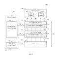
- FIG. 1 is a block diagram of a display system that includes a screen assembly that utilizes an adaptable parallax barrier to support the simultaneous display of different visual presentations to different corresponding viewers in accordance with an embodiment.
- FIG. 2 illustrates an arrangement of an adaptable parallax barrier in accordance with an embodiment that supports a particular three-dimensional viewing configuration.
- FIG. 3 illustrates an arrangement of an adaptable parallax barrier in accordance with an alternate embodiment that supports a particular three-dimensional viewing configuration.
- FIG. 4 illustrates an arrangement of an adaptable parallax barrier in accordance with an embodiment that supports a viewing configuration that mixes two-dimensional and three-dimensional viewing regions.
- FIG. 5 illustrates an arrangement of an adaptable parallax barrier in accordance with an embodiment in which different orientations of transparent and opaque slits are used to simultaneously support different viewer orientations.
- FIG. 6 shows a cross-sectional view of a display system configured to simultaneously deliver two different two-dimensional images to two different viewers, respectively, in accordance with an embodiment.
- FIG. 7 is a block diagram of a display system that includes a screen assembly that utilizes multiple parallax barriers to support the simultaneous display of multiple visual presentations in accordance with an embodiment.
- FIGS. 8 and 9 show cross-sectional views of a display system configured to simultaneously deliver two different three-dimensional images to two different viewers, respectively, in accordance with an embodiment.
- FIG. 10 depicts a flowchart of a method for controlling a pixel array to support a same viewing configuration as an adaptable light manipulator in accordance with an embodiment.
- FIG. 11 depicts a flowchart of an alternate example method for controlling a pixel array to support a same viewing configuration as an adaptable light manipulator in accordance with an embodiment.
- FIG. 12 illustrates a portion of a pixel array to which image pixels have been mapped to support a two-dimensional viewing configuration of an adaptable light manipulator in accordance with an embodiment.
- FIG. 13 illustrates how image pixels are mapped to the portion of the pixel array shown in FIG. 12 to support a first three-dimensional viewing configuration of an adaptable light manipulator in accordance with an embodiment.
- FIG. 14 illustrates how image pixels are mapped to the portion of the pixel array shown in FIGS. 12 and 13 to support a second three-dimensional viewing configuration of an adaptable light manipulator in accordance with an embodiment.
- FIG. 15 is a block diagram of an example display system that utilizes an adaptable parallax barrier and a light generator to support multiple viewing configurations in accordance with an embodiment.
- FIG. 16 provides an exploded view of a display system that utilizes a controllable backlight array to provide regional luminosity control in accordance with an embodiment.
- FIG. 17 is a block diagram of a display system that includes a pixel array disposed between a light generator and an adaptable parallax barrier in accordance with an embodiment.
- FIG. 18 provides an exploded view of a display system that implements a regional brightness control scheme based on pixel intensity in accordance with an embodiment.
- FIG. 19 illustrates a front perspective view of a display panel of a display system in accordance with an embodiment.
- FIG. 20 illustrates two exemplary configurations of an adaptable light manipulator that includes a parallax barrier and a brightness regulation overlay in accordance with an embodiment.
- FIG. 21 shows a perspective view of an adaptable lenticular lens that may be used in a displays system in accordance with an embodiment.
- FIG. 22 shows a side view of the adaptable lenticular lens of FIG. 21 .
- FIG. 23 is a block diagram of an example implementation of a display system that includes an adaptable screen assembly that supports the simultaneous display of different visual presentations to different corresponding viewers in accordance with an embodiment.
- FIG. 24 is a block diagram of an example communication system that comprises a communication infrastructure that includes simultaneous pathways for multi-viewer support in accordance with an embodiment.
- FIG. 25 is a block diagram of an example communication system that comprises a communication infrastructure that includes simultaneous pathways for multi-viewer support in accordance with a further embodiment.
- FIG. 26 illustrates a first example viewing environment in which a shared display screen of a communication system in accordance with an embodiment is used to simultaneously deliver a first visual experience to a first viewer and deliver a second visual experience to a second viewer.
- FIG. 27 illustrates a second example viewing environment in which a shared display screen of a communication system in accordance with an embodiment is used to simultaneously deliver a first visual experience to a first viewer and deliver a second visual experience to a second viewer.
- FIG. 28 depicts a flowchart of a method for operating a communication system that utilizes multiple pathways to simultaneously deliver media content to multiple corresponding viewers via a shared display screen.
- references in the specification to “one embodiment,” “an embodiment,” “an example embodiment,” etc., indicate that the embodiment described may include a particular feature, structure, or characteristic, but every embodiment may not necessarily include the particular feature, structure, or characteristic. Moreover, such phrases are not necessarily referring to the same embodiment. Further, when a particular feature, structure, or characteristic is described in connection with an embodiment, it is submitted that it is within the knowledge of one skilled in the art to effect such feature, structure, or characteristic in connection with other embodiments whether or not explicitly described.
- a communication system is described herein that allows co-located viewers to simultaneously consume different media content, such as different video content, via the same display screen, wherein video content delivered to at least one co-located viewer is not visible to the other co-located viewer(s).
- the communication system comprises an infrastructure that includes multiple pathways for delivering media content from one or more media sources to the eyes of each of the co-located viewers, wherein each pathway passes through the pixels of a pixel array included in the shared display screen.
- the pathways also include distributed or non-distributed processing circuitry that manages certain resources that are shared among the multiple pathways, wherein such shared resources may include shared display resources (e.g., pixels of the pixel array and light generated thereby) and shared data communication resources (e.g., bandwidth on data communication links and processing resources of nodes located on such links).
- shared display resources e.g., pixels of the pixel array and light generated thereby
- shared data communication resources e.g., bandwidth on data communication links and processing resources of nodes located on such links.
- the processing circuitry manages the shared resources by managing the utilization thereof to simultaneously support the multiple pathways. In further embodiments, the processing circuitry manages the shared resources by setting up or modifying an allocation of a shared resource among the multiple pathways based on an ascertained characteristic associated with at least one of the pathways.
- the processing circuitry may be configured to receive feedback and/or to gather pathway characteristics to facilitate resource allocation decisions. By simultaneously and adaptively managing each of the pathways, the processing circuitry can provide a stable, simultaneous, multiple-viewer viewing environment that can adapt over time as underlying pathway characteristics change.
- various exemplary screen assemblies that support such simultaneous viewing will first be described.
- the various screen assemblies described in this section rely on spatial filtering by one or more light manipulators (e.g. parallax barriers or lenticular lenses) to support the simultaneous viewing of different media content by different viewers.
- communication systems in accordance with embodiments may include screen assemblies that utilize other mechanisms for facilitating such simultaneous viewing (e.g., such as those designed for use in conjunction with shutter glasses).
- FIG. 1 is a block diagram of a display system 100 that includes a screen assembly 104 that utilizes an adaptable parallax barrier to support the simultaneous display of different visual presentations to different corresponding viewers in accordance with an embodiment.
- display system 100 includes driver circuitry 102 and a screen assembly 104 , wherein screen assembly 104 include a pixel array 122 and an adaptable parallax barrier 124 .
- driver circuitry 102 includes pixel array driver circuitry 112 and adaptable parallax barrier driver circuitry 114 .
- Pixel array 122 comprises a two-dimensional array of pixels (e.g., arranged as a grid or other distribution) that operates to emit light 132 .
- Pixel array 122 may comprise a self-illuminating or light-generating pixel array such that the pixels of pixel array 122 each emit light included in light 132 .
- each pixel in pixel array 122 may operate to selectively pass light emitted by a backlighting source (not shown in FIG. 1 ) to produce light 132 .
- Each pixel of pixel array 122 may be individually controllable to vary color and intensity.
- each pixel of pixel array 122 may include a plurality of sub-pixels that correspond to separate color channels, such as a trio of red, green, and blue sub-pixels included in each pixel.
- Adaptable parallax barrier 124 is positioned proximate to a surface of pixel array 122 .
- Barrier element array 142 is a layer of adaptable parallax barrier 124 that includes a plurality of barrier elements or blocking regions arranged in an array. Each barrier element of the array is configured to be selectively opaque or transparent. Combinations of barrier elements may be configured to be selectively opaque or transparent to enable various effects.
- the states of the barrier elements of barrier element array 142 may be configured such that light 132 emanating from pixel array 122 is filtered to produce filtered light 134 , wherein filtered light 134 includes one or more two-dimensional and/or three-dimensional images that may be viewed by viewers 136 in a viewing space 106 .
- each barrier element may have a round, square, or rectangular shape, and barrier element array 142 may have any number of rows of barrier elements that extend a vertical length of barrier element array 142 .
- each barrier element may have a “band” shape that extends a vertical length of barrier element array 142 , such that barrier element array 142 includes a single horizontal row of barrier elements.
- Each barrier element may include one or more of such bands, and different regions of barrier element array 142 may include barrier elements that include different numbers of such bands.
- barrier elements may be capable of being completely transparent or opaque, and in other embodiments, barrier elements may not be capable of being fully transparent or opaque.
- barrier elements may be capable of being 95% transparent when considered to be “transparent” and may be capable of being 5% transparent when considered to be “opaque.”
- Transparent and opaque as used herein are intended to encompass barrier elements being substantially transparent (e.g., greater than 75% transparent, including completely transparent) and substantially opaque (e.g., less than 25% transparent, including completely opaque), respectively.
- Driver circuitry 102 receives control signals 108 from control circuitry (not shown in FIG. 1 ).
- the control signals 108 cause driver circuitry 102 to place screen assembly 104 in a selected one of a plurality of different viewing configurations.
- adaptable parallax barrier driver circuitry 114 transmits drive signals 154 that cause barrier element array 142 to be placed in a state that supports the selected viewing configuration.
- the selected viewing configuration may be a particular two-dimensional viewing configuration, a particular three-dimensional viewing configuration, or a viewing configuration that supports the simultaneous display of different types of two-dimensional and/or three-dimensional content.
- FIG. 2 shows an arrangement of an adaptable parallax barrier 200 that supports a particular three-dimensional viewing configuration.
- Adaptable parallax barrier 200 is an example of adaptable parallax barrier 124 of FIG. 1 .
- adaptable parallax barrier 200 includes a barrier element array 202 , which includes a plurality of barrier elements 204 arranged in a two-dimensional array.
- barrier element array 202 includes a plurality of parallel strips of barrier elements 204 that are selected to be non-blocking to form a plurality of parallel non-blocking strips (or “slits”) 206 a - 206 g .
- slits or “slitslitslits”
- non-blocking strips 206 a - 206 g are alternated with parallel blocking strips 208 a - 208 g of barrier elements 204 that are selected to be blocking.
- non-blocking strips 206 a - 206 g and blocking strips 208 a - 208 g each have a width (along the x-dimension) of two barrier elements 204 , and have lengths that extend along the entire y-dimension (twenty barrier elements 204 ) of barrier element array 202 , although in other embodiments, may have alternative dimensions.
- Non-blocking strips 206 a - 206 g and blocking strips 208 a - 208 g form a parallax barrier configuration for adaptable parallax barrier 200 .
- the spacing (and number) of parallel non-blocking strips 206 in barrier element array 202 may be selectable by choosing any number and combination of particular strips of barrier elements 204 in barrier element array 202 to be non-blocking, to be alternated with blocking strips 208 , as desired. For example, hundreds, thousands, or even larger numbers of non-blocking strips 206 and blocking strips 208 may be present in adaptable parallax barrier 200 .
- FIG. 3 shows an alternative example of an adaptable parallax barrier 300 that has also been configured to support a particular three-dimensional viewing configuration.
- adaptable parallax barrier 300 includes a barrier element array 302 , which includes a plurality of barrier elements 304 arranged in a two-dimensional array (28 ⁇ 1 array).
- Barrier elements 304 have widths (along the x-dimension) similar to the widths of barrier elements 204 in FIG. 2 , but have lengths that extend along the entire vertical length (y-dimension) of barrier element array 302 . As shown in FIG.
- barrier element array 302 includes parallel non-blocking strips 306 a - 306 g alternated with parallel blocking strips 308 a - 308 g .
- parallel non-blocking strips 306 a - 306 g and parallel blocking strips 308 a - 308 g each have a width (along the x-dimension) of two barrier elements 304 , and have lengths that extend along the entire y-dimension (one barrier element 304 ) of barrier element array 302 .
- Each of adaptable parallax barriers 200 and 300 configured in the manner shown in FIGS. 2 and 3 respectively, filter light produced or passed by a pixel array to form one or more three-dimensional views in a viewing space, thus supporting a three-dimensional viewing configuration.
- all of the barrier elements of either adaptable parallax barrier 200 or 300 can simply be placed in a non-blocking state. Additional details concerning how the adaptable parallax barriers operate to support such three-dimensional viewing may be found, for example, in commonly-owned, co-pending U.S. patent application Ser. No. 12/845,409, filed on Jul. 28, 2010, and entitled “Display with Adaptable Parallax Barrier,” the entirety of which is incorporated by reference herein.
- the entirety of the barrier element array is filled with parallel non-blocking strips to support three-dimensional viewing.
- one or more regions of an adaptable parallax barrier may be filled with parallel non-blocking strips to deliver three-dimensional images, and one or more other regions of the adaptable parallax barrier may be rendered transparent to deliver two-dimensional images.
- a viewing configuration that mixes two-dimensional and three-dimensional viewing regions may be supported.
- FIG. 4 shows an arrangement of an adaptable parallax barrier 400 that supports a viewing configuration that mixes two-dimensional and three-dimensional viewing regions according to example embodiments.
- Adaptable parallax barrier 400 is similar to adaptable parallax barrier 200 of FIG. 2 , having barrier element array 202 including a plurality of barrier elements 204 arranged in a two-dimensional array.
- a first region 402 of barrier element array 202 includes a plurality of parallel non-blocking strips alternated with parallel blocking strips that together fill first region 402 .
- a second region 404 of barrier element array 202 is surrounded by first region 402 .
- Second region 404 is a rectangular shaped region of barrier element array 202 that includes a two-dimensional array of barrier elements 204 that are non-blocking.
- barrier element array 202 is configured to enable a three-dimensional image to be generated by pixels of a pixel array that are adjacent to barrier elements of first region 402 , and to enable a two-dimensional image to be generated by pixels of the pixel array that are adjacent to barrier elements inside of second region 404 .
- first region 402 may include all non-blocking barrier elements 202 to pass a two-dimensional image
- second region 404 may include parallel non-blocking strips alternated with parallel blocking strips to pass a three-dimensional image.
- adaptable parallax barrier 400 may have additional numbers, sizes, and arrangements of regions configured to pass different combinations of two-dimensional images and three-dimensional images.
- different regions of an adaptable parallax barrier that have parallel non-blocking strips may have the parallel non-blocking strips oriented at different angles to deliver three-dimensional images to viewers that are oriented differently.
- a viewing configuration that mixes three-dimensional viewing regions having different viewing orientations may be supported.
- FIG. 5 shows an arrangement of an adaptable parallax barrier 500 in which transparent slits have different orientations, according to an example embodiment.
- Adaptable parallax barrier 500 is similar to adaptable parallax barrier 200 of FIG. 2 , having barrier element array 202 including a plurality of barrier elements 204 arranged in a two-dimensional array.
- a first region 510 e.g., a bottom half
- barrier element array 202 includes a first plurality of parallel strips of barrier elements 204 that are selected to be non-blocking to form a first plurality of parallel non-blocking strips 502 a - 502 e (each having a width of two barrier elements 204 ).
- FIG. 5 shows an arrangement of an adaptable parallax barrier 500 in which transparent slits have different orientations, according to an example embodiment.
- Adaptable parallax barrier 500 is similar to adaptable parallax barrier 200 of FIG. 2 , having barrier element array 202 including a plurality of barrier elements 204
- parallel non-blocking strips 502 a - 502 e are alternated with parallel blocking strips 504 a - 504 f of barrier elements 204 (each having a width of three barrier elements 204 ).
- Parallel non-blocking strips 502 a - 502 e are oriented in a first direction (e.g., along a vertical axis).
- a second region 512 (e.g., a top half) of barrier element array 202 includes a second plurality of parallel strips of barrier elements 204 that are selected to be non-blocking to form a second plurality of parallel non-blocking strips 506 a - 506 d (each having a width of one barrier element 204 ).
- parallel non-blocking strips 506 a - 506 d are alternated with parallel blocking strips 508 a - 508 c of barrier elements 204 (each having a width of two barrier elements 204 ).
- Parallel non-blocking strips 506 a - 506 d are oriented in a second direction (e.g., along a horizontal axis).
- first and second pluralities of parallel non-blocking strips 502 a - 502 e and 506 a - 506 d are present in barrier element array 202 that are oriented perpendicularly to each other.
- the region of barrier element array 202 that includes first plurality of parallel non-blocking strips 502 a - 502 e may be configured to deliver a three-dimensional image in a viewing space to be viewable by a user whose body is oriented vertically (e.g., sitting upright or standing up).
- the region of barrier element array 202 that includes second plurality of parallel non-blocking strips 506 a - 506 d may be configured to deliver a three-dimensional image in a viewing space to be viewable by a user whose body is oriented horizontally (e.g., laying down). In this manner, users who are oriented differently relative to each other can still each be provided with a corresponding three-dimensional image that accommodates their position.
- Display system 100 may be further configured to simultaneously generate multiple two-dimensional images or views for viewing by different viewers in a viewing space.
- FIG. 6 shows a display system 600 configured to simultaneously deliver two different two-dimensional images to two different viewers, respectively, in accordance with an embodiment.
- Display system 600 may comprise one implementation of display system 100 of FIG. 1 .
- display system 600 includes a pixel array 602 and a barrier element array 604 .
- Pixel array 602 includes a plurality of pixels 614 a - 614 d and 616 a - 616 d .
- Pixels 614 alternate with pixels 616 , such that pixels 614 a - 614 d and 616 a - 616 d are arranged in series in the order of pixels 614 a , 616 a , 614 b , 616 b , 614 c , 616 c , 614 d , and 616 d .
- Further pixels may be included in pixel array 602 that are not visible in FIG. 6 , including further pixels along the width dimension of pixel array 602 (e.g., in the left-right directions) as well as pixels along a length dimension of pixel array 602 (not visible in FIG. 6 ).
- Each of pixels 614 a - 614 d and 616 a - 616 d emits light, which emanates from a display surface 624 of pixel array 602 (e.g., generally upward in FIG. 6 ) towards barrier element array 604 .
- Some example indications of light emanating from pixels 614 a - 614 d and 616 a - 616 d are shown in FIG. 6 (as dotted lines), including light 624 a and light 618 a emanating from pixel 614 a , light 624 b , light 618 b , and light 624 c emanating from pixel 614 b , etc.
- Light emanating from pixel array 602 is filtered by barrier element array 604 to form a plurality of images in a viewing space 626 , including a first image 632 a at a first location 636 a and a second image 632 b at a second location 636 b .
- a portion of the light emanating from pixel array 602 is blocked by blocking barrier elements 610 , while another portion of the light emanating from pixel array 602 passes through non-blocking barrier elements 612 , according to the filtering by barrier element array 604 .
- light 624 a from pixel 614 a is blocked by blocking barrier element 610 a
- light 624 b and light 624 c from pixel 614 b are blocked by blocking barrier elements 610 b and 610 c , respectively.
- light 618 a from pixel 614 a is passed by non-blocking barrier element 612 a
- light 618 b from pixel 614 b is passed by non-blocking barrier element 612 b.
- System 600 shown in FIG. 6 is configured to form first and second images 632 a and 632 b at locations 636 a and 636 b , respectively, which are positioned at a distance 628 from pixel array 602 .
- pixel array 602 includes a first set of pixels 614 a - 614 d and a second set of pixels 616 a - 616 d .
- Pixels 614 a - 614 d correspond to first image 632 a and pixels 616 a - 616 d correspond to second image 632 b .
- first and second images 632 a and 632 b are formed at locations 636 a and 636 b , respectively.
- light 618 a - 618 d from the first set of pixels 614 a - 614 d is focused at location 636 a to form first image 632 a at location 636 a .
- Light 620 a - 620 d from the second set of pixels 616 a - 616 d is focused at location 636 b to form second image 632 b at location 636 b.
- first viewer 634 a receives first image 632 a at first location 636 a and a second viewer 634 b receives second image 632 b at second location 636 b , according to an example embodiment.
- First and second images 632 a and 632 b may each comprise a different two-dimensional image that may be viewed independently from each other.
- first image 632 a and second image 632 b may be generated by display system 600 from first media content and second media content, respectively, that are independent of each other.
- First image 632 a may be received by both eyes of first viewer 634 a to be perceived by first viewer 634 a as a first two-dimensional image
- second image 632 b may be received by both eyes of second viewer 634 b to be perceived by second viewer 634 b as a second two-dimensional image.
- first and second images 632 a and 632 b may be generated to have a spacing that enables them to be separately viewed by first and second users 634 a and 634 b .
- first and second images 632 a and 632 b may be delivered to different viewer locations as determined by a configuration of display system 600 , including a width and spacing of non-blocking slits in barrier element array 604 and by a spacing between pixel array 602 and barrier element array 604 .
- display system 600 has a single viewing plane or surface (e.g., a plane or surface of pixel array 602 , barrier element array 604 , and/or display screen of display system 600 ) that supports multiple viewers with media content in the form of images or views.
- the single viewing plane of display system 600 may provide a first two-dimensional view based on first two-dimensional media content to first viewer 634 a , and may provide a second two-dimensional view based on second two-dimensional media content to second viewer 634 b .
- Barrier element array 604 causes the first media content to be presented to first viewer 634 a via a first area of the single viewing plane, but not to second viewer 634 b , while simultaneously causing the second media content to be presented to second viewer 634 b via a second area of the single viewing plane, but not to first viewer 634 a . Furthermore, the first area and second area of the single viewing plane that provide the first and second media content overlap each other at least in part, as barrier element array 604 enables both two-dimensional views to be provided from first set of pixels 614 a - 614 d and second set of pixels 616 a - 616 d , which are interleaved with each other. In accordance with certain configurations of display system 600 , the first and second areas may be the same area and the area may encompass the entirety of the display screen or surface of display system 600 or only a region of the display screen or surface of display system 600 .
- first and second viewers 634 a and 634 b may each wear a pair of 3D-enabled glasses, and the first and second media content associated with first and second images 632 a and 632 b , respectively, may be three-dimensional media content.
- the 3D-enabled glasses may be color filtering glasses.
- the color filter lenses of the glasses worn by first viewer 634 a may pass two-dimensional images (included in first image 632 a ) of differing perspective to the left and right eyes of first viewer 634 a to be perceived by first viewer 634 a as a first three dimensional image.
- the color filter lenses of the glasses worn by second viewer 634 b may pass two-dimensional images (included in second image 632 b ) of differing perspective to the left and right eyes of second viewer 634 b to be perceived by second viewer 634 b as a second three dimensional image.
- the 3D-enabled glasses may be shutter lensed glasses.
- the shutter lenses of the glasses worn by first viewer 634 a may be synchronized to pass two-dimensional images (included in first image 632 a ) of differing perspective to the left and right eyes of first viewer 634 a to be perceived by first viewer 634 a as a first three dimensional image.
- the shutter lenses of the glasses worn by second viewer 634 b may be synchronized to pass two-dimensional images (included in second image 632 b ) of differing perspective to the left and right eyes of second viewer 634 b to be perceived by second viewer 632 b as a second three dimensional image.
- display system 600 has a single viewing plane or surface (e.g., a plane or surface of pixel array 602 or barrier element array 604 ) that supports multiple viewers with media content in the form of three-dimensional images or views.
- the single viewing plane of display system 600 may provide a first three-dimensional view based on first three-dimensional media content to first viewer 634 a , and may provide a second three-dimensional view based on second three-dimensional media content to second viewer 634 b .
- Barrier element array 604 causes the first three-dimensional media content to be presented to first viewer 634 a via a first area of the single viewing plane, but not to second viewer 634 b , while simultaneously causing the second three-dimensional media content to be presented to second viewer 634 b via a second area of the single viewing plane, but not to first viewer 634 a . Furthermore, the first area and second area of the single viewing plane that provide the first and second media content overlap each other at least in part, as barrier element array 604 enables both three-dimensional views to be provided from first set of pixels 614 a - 614 d and second set of pixels 616 a - 616 d , which are interleaved with each other. In accordance with certain configurations of display system 600 , the first and second areas may be the same area and the area may encompass the entirety of the display screen or surface of display system 600 or only a region of the display screen or surface of display system 600 .
- display system 600 can be configured to deliver a single two-dimensional or three-dimensional view to a viewer, to deliver a pair of two-dimensional views to a pair of viewers, or to deliver a pair of three-dimensional views to a pair of viewers.
- Display system 600 can be configured to switch between delivering views to one and two viewers by turning off or turning on, respectively, the display of media content by pixel array 602 associated with one of the viewers (e.g., by turning off or on pixels 616 associated with second image 632 b ).
- Display system 600 can be configured to switch between delivering two-dimensional and three-dimensional views by providing the corresponding media content type at pixel array 602 .
- Display systems in accordance with further embodiments may include multiple layers of parallax barriers. Such display systems may enable multiple three-dimensional images to be displayed in a viewing space.
- the multiple parallax barrier layers may enable spatial separation of the images.
- a display device that includes multiple parallax barrier layers may be configured to display a first three-dimensional image in a first region of a viewing space (e.g., a left-side area), a second three-dimensional image in a second region of the viewing space (e.g., a central area), a third three-dimensional image in a third region of the viewing space (e.g., a right-side area), etc.
- a display device that includes multiple parallax barrier layers may be configured to display any number of spatially separated three-dimensional images as desired for a particular application (e.g., according to a number and spacing of viewers in the viewing space, etc.).
- FIG. 7 is a block diagram of a display system 700 that includes multiple parallax barrier layers in accordance with an embodiment.
- display system 700 includes driver circuitry 702 and a screen assembly 704 , wherein screen assembly 704 includes a pixel array 722 , a first parallax barrier 724 and a second parallax barrier 726 .
- first parallax barrier 724 includes a first barrier element array 742
- second parallax barrier 726 includes a second barrier element array 744 .
- driver circuitry 702 includes pixel array driver circuitry 712 and parallax barrier driver circuitry 714 .
- Pixel array 722 may comprise a self-illuminating or light-generating pixel array such that the pixels of pixel array 722 each emit light included in light 732 .
- each pixel in pixel array 722 may operate to selectively pass light emitted by a backlighting source (not shown in FIG. 7 ) to produce light 732 .
- Pixel array driver circuitry 712 may generate drive signals 752 based on a control signal 708 received from control circuitry (not shown in FIG. 7 ) and pixel array 722 may emit light 732 in accordance with the received drive signals 752 .
- pixel array driver circuitry 712 may generate drive signals 752 to cause pixel array 722 to emit light 732 containing a plurality of images corresponding to different sets of pixels.
- First parallax barrier 724 may be configured to filter light 732 received from pixel array 722 . As shown in FIG. 7 , first parallax barrier 724 includes first barrier element array 742 that filters light 732 to generate filtered light 734 . First barrier element array 742 may optionally be configurable to adjust the filtering performed by first parallax barrier 724 in a similar manner to that described above in regard to adaptable parallax barrier 124 or in another manner. In an embodiment, parallax barrier driver circuitry 714 may generate drive signals 754 based on control signal 708 received by driver circuitry 702 to cause first barrier element array 742 to filter light 732 as desired.
- Filtered light 734 is received by second parallax barrier 726 to generate filtered light 736 that includes a plurality of three-dimensional images 762 1 - 762 n formed in a viewing space 706 .
- second parallax barrier 726 includes second barrier element array 744 that filters filtered light 734 to generate filtered light 736 .
- Second barrier element array 744 may optionally be configurable to adjust the filtering performed by second parallax barrier 726 in a similar manner to that described above in regard to adaptable parallax barrier 124 or in another manner.
- parallax barrier driver circuitry 714 may generate drive signals 756 based on control signal 708 to cause barrier element array 744 to filter filtered light 734 to generate filtered light 736 including three-dimensional images 762 1 - 762 n as desired.
- display system 700 has a single viewing plane or surface (e.g., a plane or surface of pixel array 722 , first parallax barrier 724 , second parallax barrier 726 , or a display screen of display system 700 ) that supports multiple viewers with media content in the form of three-dimensional images or views.
- the single viewing plane of display system 700 may provide a first three-dimensional view based on first three-dimensional media content to a first viewer, a second three-dimensional view based on second three-dimensional media content to a second viewer, and optionally further three-dimensional views based on further three-dimensional media content to further viewers.
- First and second parallax barrier 724 and 726 cause each three-dimensional media content to be presented to a corresponding viewer via a corresponding area of the single viewing plane, with each viewer being enabled to view corresponding media content without viewing media content directed to other viewers.
- the areas of the single viewing plane that provide the various three-dimensional views of media content overlap each other at least in part.
- the areas may be the same area—an area of a display screen or surface of display system 700 .
- the areas may be the same area and the area may encompass the entirety of the display screen or surface of display system 700 or only a region of the display screen or surface of display system 700 .
- Display system 700 may be configured in various ways to generate multiple three-dimensional images in embodiments. Furthermore, as described below, embodiments of display system 700 may be configured to generate two-dimensional views, as well as any combination of one or more two-dimensional views simultaneously with one or more three-dimensional views. Examples of such embodiments are provided in the following.
- FIG. 8 shows a cross-sectional view of a display system 800 , which is an example implementation of system 700 shown in FIG. 7 .
- system 800 includes a pixel array 802 , a first barrier element array 804 , and a second barrier element array 806 .
- System 800 may also include display controller 702 of FIG. 7 , which is not shown in FIG. 8 for ease of illustration.
- System 800 is described as follows.
- pixel array 802 includes a first set of pixels 814 a - 814 c , a second set of pixels 816 a - 816 c , a third set of pixels 818 a - 818 c and a fourth set of pixels 820 a - 820 c .
- Pixels of the four sets of pixels are alternated in pixel array 802 in the order of pixel 814 a , pixel 816 a , pixel 818 a , pixel 820 a , pixel 814 b , pixel 816 b , etc.
- Further pixels may be included in each set of pixels in pixel array 802 that are not visible in FIG. 8 , including hundreds, thousands, or millions of pixels in each set of pixels.
- Each of pixels 814 a - 814 c , 816 a - 816 c , 818 a - 818 c and 820 a - 820 c is configured to emit light, which emanates from the surface of pixel array 802 towards first barrier element array 804 .
- Each set of pixels is configured to generate a corresponding image.
- FIG. 9 shows display system 800 , where pixels of pixel array 802 emit light.
- Light from second set of pixels 816 a - 816 c and first set of pixels 814 a - 814 c is configured to generate third and fourth images 906 c and 906 d , respectively, which may be perceived together as a second three-dimensional image by a second viewer 904 b .
- Light from fourth set of pixels 820 a - 820 c and third set of pixels 818 a - 818 c is configured to generate first and second images 906 a and 906 b , respectively, which may be perceived together as a first three-dimensional image by a first viewer 904 a .
- the light emitted by the sets of pixels is filtered by first and second barrier element arrays 804 and 806 to generate the first and second three-dimensional images in respective desired regions of a viewing space 902 adjacent to display system 800 .
- pixels 814 a - 814 c correspond to fourth image 906 d
- pixels 816 a - 816 c correspond to third image 906 c
- pixels 818 a - 818 c correspond to second image 906 b
- pixels 820 a - 820 c correspond to first image 906 a .
- light from the first set of pixels 814 a - 814 c forms fourth image 906 d and light from the third set of pixels 818 a - 818 c forms second image 906 b , due to the filtering of the non-blocking slits in first and second barrier element arrays 804 and 806 .
- light from the second set of pixels 816 a - 816 c forms third image 906 c and light from the fourth set of pixels 820 a - 820 c forms first image 906 a.
- third and fourth images 906 c and 906 d may be configured to be perceived by viewer 904 b as a second three-dimensional image, such that third image 906 c is received at a right eye location 908 c of viewer 904 b and fourth image 906 d is received at a second eye location 908 d of viewer 904 b.
- First-fourth images 906 a - 906 d may be formed in viewing space 902 at a distance from pixel array 802 and at a lateral location of viewing space 902 as determined by a configuration of display system 800 , including by a width and spacing of non-blocking slits in first barrier element array 804 , by a width and positioning of non-blocking slits in second barrier element array 806 , by a spacing between pixel array 802 and first barrier element array 804 , and a spacing between first and second barrier element arrays 804 and 806 .
- display system 800 may deliver a two-dimensional view to one of viewers 904 a and 904 b , and may simultaneously deliver a three-dimensional view to the other of viewers 904 a and 904 b .
- pixels 814 a - 814 c and pixels 816 a - 816 c may deliver the same images (e.g., may display the same media content), such that third and fourth images 906 c and 906 d are the same.
- pixels 814 a - 814 c may be turned off, and a width of slits 812 a , 812 c , and 812 e may be adjusted such that pixels 816 a - 816 c deliver a same view to both right and left eye locations 908 c and 908 d of viewer 904 b (through slits 824 a - 824 c ).
- first and second images 906 a and 906 b may be simultaneously delivered to first viewer 904 a as differing perspective images to be perceived as a three-dimensional view or as the same image to be perceived as a second two-dimensional view.
- first barrier element array 804 and second barrier element array 806 may transition all of its barrier elements to the non-blocking state, while the other of first barrier element array 804 and second barrier element array 806 may be configured to deliver a three-dimensional view.
- a configuration of adaptable parallax barrier 124 of display system 100 or a configuration of either of first and second parallax barrier 724 and 726 of display system 700 can be dynamically modified to support a particular viewing configuration.
- the pixel array of each system must also be controlled to support the same viewing configuration.
- pixel array 122 When a configuration of adaptable parallax barrier 124 of display system 100 is modified to support a particular viewing configuration, pixel array 122 must also be controlled to support the same viewing configuration. In particular, the rendering of pixels of an image (also referred to herein as “image pixels”) among the pixels of pixel array 122 (also referred to herein as “display pixels”) must be handled in a manner that is consistent with a current configuration of adaptable parallax barrier 124 .
- This may entail, for example, changing a number of display pixels that represents each image pixel (i.e., changing the resolution of a displayed image) and/or changing which display pixels or groups thereof correspond to the respective image pixels (i.e., changing the locations at which the image pixels are displayed), in response to modification of a configuration of adaptable parallax barrier 124 .
- Such changes may be implemented by a controller (not shown in FIG. 1 ) via delivery of appropriate control signals 108 to pixel array driver circuitry 112 .
- FIG. 10 depicts a flowchart 1000 of an example method for controlling a pixel array to support the same viewing configuration as an adaptable light manipulator (such as adaptable parallax barrier 124 ) in accordance with an embodiment.
- the method of flowchart 1000 begins at step 1002 .
- a configuration of an adaptable light manipulator such as adaptable parallax barrier 124
- a number of display pixels in a pixel array such as pixel array 122 , that represents each image pixel of a plurality of image pixels is changed in response to modifying the configuration of the adaptable light manipulator.
- FIG. 13 is intended to represent the same portion of pixel array 1200 after the configuration of the adaptable light manipulator has been changed to support a three-dimensional viewing configuration.
- the three-dimensional viewing configuration requires the overlapping display of a first image and a second image across the same portion of pixel array 1200 .
- the pixel array is controlled such that 2 rather than 4 display pixels are used to present each image pixel of the first image (each still shown depicting the letter “A”). This corresponds to a decreased viewing resolution of the first image.
- the other half of the display pixels are now used to present each image pixel of a second image (each shown depicting the letter “B”).
- the image pixels associated with the different images are aligned with the adaptable light manipulator to achieve a desired three-dimensional viewing effect.
- FIG. 11 depicts a flowchart 1100 of another example method for controlling a pixel array to support the same viewing configuration as an adaptable light manipulator (such as adaptable parallax barrier 124 ) in accordance with an embodiment.
- the method of flowchart 1100 begins at step 1102 .
- a plurality of image pixels is mapped to a plurality of respective first subsets of display pixels in a pixel array, such as pixel array 122 .
- a configuration of an adaptable light manipulator that is positioned proximate to the pixel array is changed.
- FIGS. 13 and 14 provide a simple illustration of an application of the method of flowchart 1100 .
- a portion of a pixel array 1200 is used to simultaneously display a first image comprising image pixels shown depicting the letter “A” and a second image comprising image pixels shown depicting the letter “B.”
- this display format is utilized to support a three-dimensional viewing configuration corresponding to a particular arrangement of an adaptable light manipulator disposed proximate to the pixel array.
- FIG. 14 is intended to represent the same portion of pixel array 1200 after the configuration of the adaptable light manipulator has been changed to support a modified three-dimensional viewing configuration (e.g., in response to a changed location of a viewer or some other factor).
- the modified three-dimensional viewing configuration requires the display location of the first image and the second image to be shifted, as shown in FIG. 14 .
- the same image pixel 1304 is now rendered to the bottom-most two display pixels in the second column from the left of array portion 1200 .
- FIG. 15 shows a block diagram of yet another example display system 1500 that utilizes an adaptable parallax barrier to support multiple viewing configurations.
- display system 1500 includes driver circuitry 1502 and a screen assembly 1504 , wherein screen assembly 1504 include a light generator 1522 , an adaptable parallax barrier 1524 and a pixel array 1526 .
- driver circuitry 1502 includes light generator driver circuitry 1512 , adaptable parallax barrier driver circuitry 1514 and pixel array driver circuitry 1516 .
- Light generator 1522 emits light 1532 .
- Adaptable parallax barrier 1524 is positioned proximate to light generator 1522 .
- Barrier element array 1544 is a layer of adaptable parallax barrier 1524 that includes a plurality of barrier elements or blocking regions arranged in an array. Each barrier element of the array is configured to be selectively opaque or transparent.
- Barrier element array 1544 filters light 1532 received from light generator 1522 to generate filtered light 1534 .
- Filtered light 1534 is configured to enable a two-dimensional image, a three-dimensional image, or a pair of two-dimensional or three-dimensional images to be formed based on images subsequently imposed on filtered light 1534 by pixel array 1526 .
- Pixel array 1526 includes a two-dimensional array of pixels (e.g., arranged in a grid or other distribution) like pixel array 122 of FIG. 1 .
- Pixel array 1526 is not self-illuminating and operates as a light filter that imposes images (e.g., in the form of color, grayscale, etc.) on filtered light 1534 from adaptable parallax barrier 1524 to generate filtered light 1536 to include one or more images.
- Each pixel of pixel array 1526 may be a separately addressable filter (e.g., a pixel of a plasma display, an LCD display, an LED display, or of other type of display).
- Each pixel of pixel array 1526 may be individually controllable to vary the color imposed on the corresponding light passing through, and/or to vary the intensity of the passed light in filtered light 1536 .
- each pixel of pixel array 1526 may include a plurality of sub-pixels that correspond to separate color channels, such as a trio of red, green, and blue sub-pixels included in each pixel.
- Driver circuitry 1502 receives control signals 1508 from control circuitry (not shown in FIG. 15 ). Control signals 1508 cause driver circuitry 1502 to place screen 1504 in a selected one of a plurality of different viewing configurations. In particular, based on control signals 1508 , adaptable parallax barrier driver circuitry 1514 transmits drive signals 1554 that cause barrier element array 1544 to be placed in a state that supports the selected viewing configuration.
- pixel array driver circuitry 1516 transmits drive signals 1556 to cause pixels of one or more images (also referred to herein as “image pixels”) to be rendered among the pixels of pixel array 1526 (also referred to herein as “display pixels”) in a manner that is consistent with a current configuration of adaptable parallax barrier 1524 .
- the selected viewing configuration may be a particular two-dimensional viewing configuration, a particular three-dimensional viewing configuration, or a viewing configuration that supports the simultaneous display of different types of two-dimensional and/or three-dimensional content.
- conventional LCD displays typically include a backlight and a display panel that includes an array of LCD pixels.
- the backlight is designed to produce a sheet of light of uniform luminosity for illuminating the LCD pixels.
- light generator 1522 includes a backlight array 1542 which is a two-dimensional array of light sources. Such light sources may be arranged, for example, in a rectangular grid. Each light source in backlight array 1542 is individually addressable and controllable to select an amount of light emitted thereby.
- a single light source may comprise one or more light-emitting elements depending upon the implementation.
- each light source in backlight array 1542 comprises a single light-emitting diode (LED) although this example is not intended to be limiting.
- the amount of light emitted by the individual light sources that make up backlight array 1542 can selectively controlled by drive signals 1552 generated by light generator driver circuitry 1512 so that the brightness associated with each of a plurality of display regions of screen 1504 can also be controlled.
- This enables display system 1500 to provide a desired brightness level for each display region automatically and/or in response to user input.
- backlight array 1542 can be controlled such that a uniform level of brightness is achieved across different simultaneously-displayed display regions, even though the number of perceptible pixels per unit area varies from display region to display region.
- backlight array 1542 can be controlled such that the level of brightness associated with a particular display region is increased or reduced without impacting (or without substantially impacting) the brightness of other simultaneously-displayed display regions.
- FIG. 16 provides an exploded view of a display system 1600 that implements a controllable backlight array as described immediately above.
- Display system 1600 comprises one implementation of display system 1500 .
- display system 1600 includes a light generator 1602 that includes a backlight array 1612 , an adaptable parallax barrier 1604 that includes a barrier element array 1622 and a display panel 1606 that includes a pixel array 1632 . These elements may be aligned with and positioned proximate to each other to create an integrated screen assembly.
- a first portion 1634 of pixel array 1632 and a first portion 1624 of barrier element array 1622 have been manipulated to create a first display region that displays multi-view three-dimensional content
- a second portion 1636 of pixel array 1632 and a second portion 1626 of barrier element array 1622 have been manipulated to create a second display region that displays a three-dimensional image
- a third portion of 1638 of pixel array 1632 and a third portion 1628 of barrier element array 1622 have been manipulated to create a third display region that displays a two-dimensional image.
- the amount of light emitted by light sources included within a first portion 1614 , a second portion 1616 and a third portion 1618 of backlight array 1612 can respectively be controlled.
- the light sources within first portion 1614 may be controlled to provide greater luminosity than the light sources within second portion 1616 and third portion 1618 as the number of perceivable pixels per unit area will be smallest in the first display region with which first portion 1614 is aligned.
- the light sources within second portion 1616 may be controlled to provide greater luminosity than the light sources within third portion 1618 since the number of perceivable pixels per unit area will be smaller in the second display region with which second portion 1616 is aligned than the third display region with which third portion 1618 is aligned.
- the light sources within second portion 1616 may be controlled to provide greater luminosity than the light sources within third portion 1618 since the number of perceivable pixels per unit area will be smaller in the second display region with which second portion 1616 is aligned than the third display region with which third portion 1618 is aligned.
- other control schemes may be used.
- a display system in accordance with an embodiment can dynamically manipulate pixel array 1632 and barrier element array 1622 in a coordinated fashion to dynamically and simultaneously create any number of display regions of different sizes and in different locations, wherein each of the created display regions can display one of two-dimensional, three-dimensional or multi-view three-dimensional content.
- backlight array 1612 can also be dynamically manipulated in a coordinated fashion with pixel array 1632 and barrier element array 1622 to ensure that each display region is perceived at a desired level of brightness.
- each light source in backlight array 1612 there is a one-to-one correspondence between each light source in backlight array 1612 and every display pixel in pixel array 1632 .
- the number of light sources provided in backlight array 1212 is less than the number of pixels provided in pixel array 1632 .
- a single light source may be provided in backlight array 1612 for every N pixels provided in pixel array 1632 , wherein N is an integer greater than 1.
- each light source in backlight array 1612 may be arranged so that it provides backlighting for a particular group of pixels in pixel array 1632 , although this is only an example. In alternate embodiments, the number of light sources provided in backlight array 1612 is greater than the number of pixels provided in pixel array 1632 .
- light sources in backlight array 1612 are described as being individually controllable. However, in alternate embodiments, light sources in backlight array 1612 may only be controllable in groups. This may facilitate a reduction in the complexity of the control infrastructure associated with backlight array 1612 . In still further embodiments, light sources in backlight array 1612 may be controllable both individually and in groups.
- FIGS. 15 and 16 show display system configurations in which a barrier element array of an adaptable parallax barrier is disposed between a backlight array of individually addressable and controllable light sources and a pixel array
- the pixel array may be disposed between the backlight array and the barrier element array.
- FIG. 17 is a block diagram of a display system 1700 that includes a pixel array 1724 disposed between a light generator 1722 that includes a backlight array 1742 and an adaptable parallax barrier 1726 that includes a barrier element array 1744 to support the generation of two-dimensional and/or three-dimensional images perceivable in a viewing space 1706 .
- selective control of the luminosity of groups or individual ones of the light sources in backlight array 1742 may also be used to vary the backlighting luminosity associated with different display regions created by the interaction of backlight array 1742 , pixel array 1724 and barrier element array 1744 .
- FIG. 18 provides an exploded view of a display system 1800 that implements a regional brightness control scheme based on pixel intensity as described immediately above.
- display system 1800 includes a display panel 1802 and an adaptable parallax barrier 1804 .
- Display system 1800 also includes a backlight panel, although this element is not shown in FIG. 18 . These elements may be aligned with and positioned proximate to each other to create an integrated display screen.
- display panel 1802 includes a pixel array 1812 .
- Each of the pixels in a first portion 1814 of pixel array 1812 is individually controlled by pixel array driver circuitry to pass a selected amount of light produced by a backlight panel (not shown in FIG. 18 ), thereby producing display-generated light representative of a single two-dimensional image.
- Each of the pixels in a second portion 1816 of pixel array 1812 is individually controlled by the pixel array driver circuitry to pass a selected amount of light produced by the backlight panel, thereby producing display-generated light representative of two two-dimensional images that, when combined by the brain of a viewer positioned in an appropriate location relative to display system 1800 , will be perceived as a single three-dimensional image.
- Adaptable parallax barrier 1804 includes barrier element array 1822 that includes a first portion 1824 and a second portion 1826 .
- Barrier element array 1822 is aligned with pixel array 1814 such that first portion 1824 of blocking region array 1822 overlays first portion 1814 of pixel array 1812 and second portion 1826 of blocking region array 1822 overlays second portion 1816 of pixel array 1812 .
- Adaptable parallax barrier driver circuitry causes all the barrier elements within first portion 1824 of barrier element array 1822 to be transparent. Thus, the two-dimensional image generated by the pixels of first portion 1814 of pixel array 1812 will simply be passed through to a viewer in a viewing space in front of display system 1400 .
- the adaptable parallax barrier driver circuitry manipulates the barrier elements within second portion 1826 of blocking region array 1822 to form a plurality of parallel transparent strips alternated with parallel opaque strips, thereby creating a parallax effect that enables the two two-dimensional images generated by the pixels of second portion 1816 of pixel array 1812 to be perceived as a three-dimensional image by a viewer in the viewing space in front of display system 1800 .
- drive signals may be transmitted to display panel 1802 that selectively cause the pixels included in first portion 1814 of pixel array 1812 to pass less light from the backlight panel (i.e., become less intense), thereby reducing the brightness of the two-dimensional image produced from the pixels in first portion 1814 of pixel array 1812 .
- drive signals may be transmitted to display panel 1802 that selectively cause the pixels included in second portion 1816 of pixel array 1812 to pass more light from the backlight panel (i.e., become more intense), thereby increasing the brightness of the three-dimensional image produced from the pixels in second portion 1816 of pixel array 1812 .
- the intensity of the pixels in portions 1814 and 1816 of pixel array 1812 By controlling the intensity of the pixels in portions 1814 and 1816 of pixel array 1812 in this manner, the brightness of the two-dimensional image produced from the pixels in first portion 1814 of pixel array 1812 and the brightness of the three-dimensional image produced from the pixels in second portion 1816 of pixel array 1812 can be kept consistent. Additionally, by providing independent control over the intensity of the pixels in portions 1814 and 1816 of pixel array 1812 , independent control over the brightness of the two-dimensional and three-dimensional images generated therefrom can also be achieved.
- a display system in accordance with an embodiment can dynamically manipulate pixel array 1812 and blocking element array 1822 in a coordinated fashion to dynamically and simultaneously create any number of display regions of different sizes and in different locations, wherein each of the created display regions can display one of two-dimensional, three-dimensional or multi-view three-dimensional content.
- the intensity of the pixels in pixel array 1812 can also be dynamically manipulated in a coordinated fashion to ensure that each display region is perceived at a desired level of brightness.
- FIG. 19 illustrates a front perspective view of a display panel 1900 .
- Display panel 1900 includes a pixel array 1902 that includes a first portion 1904 and a second portion 1906 , wherein each of first portion 1904 and second portion 1906 includes a different subset of the pixels in pixel array 1902 . It is to be assumed that first portion 1904 of pixel array 1902 is illuminated by backlighting provided by an aligned first portion of a backlight array (not shown in FIG.
- Second portion 1906 of pixel array 1902 is illuminated by backlighting provided by an aligned second portion of the backlight array.
- the amount of light emitted by each light source in the second portion of the backlight array to illuminate second portion 1906 of pixel array 1902 is controlled such that it is greater than the amount of light emitted by each light source in the first portion of the backlight array to illuminate first portion 1904 of pixel array 1902 .
- This control scheme may be applied, for example, to cause a three-dimensional image formed by interaction between the pixels in second portion 1906 of pixel array 1902 and an adaptable parallax barrier to appear to have a uniform brightness level with respect to a two-dimensional image formed by interaction between the pixels in first portion 1904 of pixel array 1902 and the adaptable parallax barrier.
- the difference in the amount of light emitted by each light source in the first and second portions of the backlight array to illuminate corresponding first and second portions 1904 and 1906 of pixel array 1902 may also give rise to undesired visual artifacts.
- the difference may cause pixels in boundary areas immediately outside of second portion 1906 of pixel array 1902 to appear brighter than desired in relation to other pixels in first portion 1904 of pixel array 1902 .
- the pixels in boundary area 1912 immediately outside of second portion 1906 of pixel array 1902 may appear brighter than desired in relation to other pixels in first portion 1904 of pixel array 1902 .
- the difference may cause pixels in boundary areas immediately inside of second portion 1906 of pixel array 1502 to appear dimmer than desired in relation to other pixels in second portion 1906 of pixel array 1902 .
- the pixels in boundary area 1914 immediately inside of second portion 1906 of pixel array 1902 may appear dimmer than desired in relation to other pixels in second portion 1906 of pixel array 1902 .
- the reduced luminosity of the light sources in the first portion of the backlight array has “spilled over” to impact the pixels in boundary area 1914 , causing those pixels to be dimmer than desired.
- an embodiment may selectively control the amount of light passed by the pixels located in boundary region 1912 and/or boundary region 1914 to compensate for the undesired visual effects.
- driver circuitry associated with pixel array 1902 may selectively cause the pixels included in boundary area 1912 of pixel array 1902 to pass less light from the backlight panel (i.e., become less intense), thereby reducing the brightness of the pixels in boundary area 1912 , thus compensating for an undesired increase in brightness due to “spill over” from light sources in the second portion of the backlight array.
- driver circuitry associated with pixel array 1902 may selectively cause the pixels included in boundary area 1914 of pixel array 1902 to pass more light from the backlight panel (i.e., become more intense), thereby increasing the brightness of the pixels in boundary area 1914 , thus compensating for an undesired reduction in brightness due to “spill over” from light sources in the first portion of the backlight array.
- the intensity of the pixels in boundary areas 1912 and/or 1914 in this manner, the undesired visual effects described above that can arise from the use of a backlight array to provide regional brightness control can be mitigated or avoided entirely.
- FIG. 19 provides only one example of undesired visual effects that can arise from the use of a backlight array to provide regional brightness control.
- Persons skilled in the relevant art(s) will appreciate that many different display regions having many different brightness characteristics can be simultaneously generated by a display system in accordance with embodiments, thereby giving rise to different undesired visual effects relating to the brightness of boundary areas inside and outside of the different display regions. In each case, the intensity of pixels located in such boundaries areas can be selectively increased or reduced to mitigate or avoid such undesired visual effects.
- a regional brightness control scheme is implemented in a display system that does not include a backlight panel at all, but instead utilizes a display panel comprising an array of organic light emitting diodes (OLEDs) or polymer light emitting diodes (PLEDs) which function as display pixels and also provide their own illumination.
- Display system 100 described above in reference to FIG. 1 may be representative of such a system, provided that pixel array 122 comprises an array of OLEDs or PLEDs.
- the amount of light emitted by the individual OLED/PLED pixels that make up the OLED/PLED pixel array can be selectively controlled so that the brightness associated with each of a plurality of display regions of display system 100 can also be controlled.
- the OLED/PLED pixel array can be controlled such that a uniform level of brightness is achieved across different simultaneously-displayed display regions, even though the number of perceptible pixels per unit area varies from display region to display region.
- the OLED/PLED pixel array can be controlled such that the level of brightness associated with a particular display region is increased or reduced without impacting (or without substantially impacting) the brightness of other simultaneously-displayed display regions.
- OLED/PLED pixel regions such as those described above are adjacent to each other, it is possible that the brightness characteristics of one pixel region can impact the perceived brightness of an adjacent pixel region having different brightness characteristics, creating an undesired visual effect.
- a first OLED/PLED pixel region having a relatively high level of brightness to support the viewing of multi-view three-dimensional content may be adjacent to a second OLED/PLED pixel region having a relatively low level of brightness to support the viewing of two-dimensional content.
- light from pixels in a perimeter area of the first OLED/PLED pixel region that are close to the boundary between the two pixel regions may “spill over” into a perimeter area of the second OLED/PLED pixel region.
- pixels in the perimeter area of the second OLED/PLED pixel region may appear brighter than desired in relation to other pixels in the second OLED/PLED pixel region.
- pixels in the perimeter area of the first OLED/PLED pixel array may appear dimmer than desired in relation to other pixels in the first OLED/PLED pixel region because of the adjacency to the second OLED/PLED pixel region.
- a regional brightness control scheme is implemented in a display system that includes an adaptable parallax barrier that also supports brightness regulation via an “overlay” approach.
- an adaptable parallax barrier that also supports brightness regulation via an “overlay” approach.
- Such an approach involves the use of a brightness regulation overlay that is either independent of or integrated with an adaptable parallax barrier.
- the brightness regulation overlay is used to help achieve the aforementioned goals of maintaining standard brightness across various regional screen configurations and compensating for or minimizing backlighting dispersion.
- the brightness regulation overlay comprises an element that allows regional dimming through various tones of “grey” pixels.
- an adaptable parallax barrier and the brightness regulation overlay are implemented as a non-color (i.e., black, white and grayscale) LCD sandwich, although other implementations may be used.
- the combined adaptable parallax barrier and brightness regulation overlay provide full transparent or opaque states for each pixel, as well as a grayscale alternative that can be used to “balance out” brightness variations caused by the parallax barrier itself.
- Control over the individual barrier elements of the parallax barrier and the individual grayscale pixels of the brightness regulation overlay may be provided by using coordinated driver circuitry signaling.
- coordinate signaling may cause the pixels of the adaptable parallax barrier and the brightness regulation overlay (collectively referred to below as the manipulator pixels) to create opaque and transparent barrier elements associated with a particular parallax barrier configuration and a grayscale support there between to allow creation of overlays.
- FIG. 20 illustrates two exemplary configurations of an adaptable light manipulator 2000 that includes an adaptable parallax barrier and a brightness regulation overlay implemented as a light manipulating LCD sandwich with manipulator grayscale pixels.
- the grayscale pixels map to the display pixels on a one-to-one basis, but that need not be the case.
- a first exemplary configuration of adaptable light manipulator 2000 is shown above the section line denoted with reference numeral 2002 .
- a three-dimensional region 2004 is created with fully transparent or fully opaque manipulator pixels that provide parallax barrier functionality and a two-dimensional region 2006 is created having continuous medium gray manipulator pixels.
- the medium gray manipulator pixels operate to reduce the perceived brightness of two-dimensional region 2006 to better match that of three-dimensional region 2004 .
- two-dimensional region 2006 could instead comprise a three-dimensional region having a number of views that is different than three-dimensional region 2004 , thus also requiring brightness regulation.
- boundary region compensation is performed.
- a boundary region 2010 within two-dimensional region 2006 may be “lightened” to a light gray to compensate for any diminution of light that might occur near the boundary with three-dimensional region 2004 .
- the grayscale level of an inner portion 2008 of two-dimensional region 2006 is maintained at the same medium gray level as in the portion of two-dimensional region 2006 above section line 2002 .
- a first boundary region 2012 and a second boundary region 2014 within three-dimensional region 2004 comprise darker and lighter gray transitional areas, respectively, to account for light dispersion from two-dimensional region 2006 .
- an inner portion 2016 of three-dimensional region 2004 includes only fully transparent or fully opaque manipulator pixels consistent with a parallax barrier configuration and no brightness regulation.
- the configuration of adaptable light manipulator 2000 is achieved by first creating a white through various grayscale areas that correspond to the regions and boundary areas to be formed. Once established, the manipulator pixels in these areas that comprise the opaque portions of the parallax barrier are overwritten to turn them black.
- this two-stage approach is conceptual only and no “overwriting” need be performed.
- adaptable light manipulator 2000 comprises the only component used in a display system for performing brightness regulation and/or boundary region compensation.
- the display system further utilizes any one or more of the following aforementioned techniques for performing brightness regulation and/or boundary region compensation: a backlight array with independently-controllable light sources, and/or a pixel array and associated control logic for selectively increasing or decreasing the intensity of display pixels (e.g., either LCD pixels or OLED/PLED pixels).
- a backlight array with independently-controllable light sources and/or a pixel array and associated control logic for selectively increasing or decreasing the intensity of display pixels (e.g., either LCD pixels or OLED/PLED pixels).
- adaptable light manipulator 2000 is implemented as an integrated adaptable parallax barrier and brightness regulation overlay.
- adaptable light manipulator 2000 is implemented using an adaptable parallax barrier panel and an independent brightness regulation overlay panel.
- any of the non-uniform light generation schemes described above may also be used in conjunction with a display system that includes multiple parallax barriers, such as display system 700 of FIG. 7 , to support simultaneous presentation of regional two-dimensional, three-dimensional and multi-view three dimensional views.
- each region supported by such non-uniform light generation may comprise a region that simultaneously presents multiple different two-dimensional and/or three-dimensional views to multiple respective viewers.
- an adaptable lenticular lens may be used.
- adaptable parallax barrier 124 may be replaced with an adaptable lenticular lens.
- first parallax barrier 724 or second parallax barrier 726 may be replaced with a lenticular lens, such as an adaptable lenticular lens.
- FIG. 21 shows a perspective view of an adaptable lenticular lens 2100 in accordance with an embodiment.
- adaptable lenticular lens 2100 includes a sub-lens array 2102 .
- Sub-lens array 2102 includes a plurality of sub-lenses 2104 arranged in a two-dimensional array (e.g., arranged side-by-side in a row).
- Each sub-lens 2104 is shown in FIG. 21 as generally cylindrical in shape and having a substantially semi-circular cross-section, but in other embodiments may have other shapes.
- sub-lens array 2102 is shown to include eight sub-lenses for illustrative purposes and is not intended to be limiting.
- sub-lens array 2102 may include any number (e.g., hundreds, thousands, etc.) of sub-lenses 2104 .
- FIG. 22 shows a side view of adaptable lenticular lens 2100 .
- light may be passed through adaptable lenticular lens 2100 in the direction of dotted arrow 2202 to be diverted.
- Adaptable lenticular lens 2100 is adaptable in that it can be modified to manipulate light in different ways in order to accommodate different viewing configurations.
- adaptable lenticular lens is made from an elastic material and can be stretched or shrunk in one or more directions in response to generated drive signals.
- FIG. 23 is a block diagram of an example implementation of a display system 2300 that includes an adaptable screen assembly that supports the simultaneous display of multiple visual presentations in accordance with an embodiment.
- display system 2300 generally comprises control circuitry 2302 , driver circuitry 2304 and an adaptable screen assembly 2306 .
- control circuitry 2302 includes a processing unit 2314 , which may comprise one or more general-purpose or special-purpose processors or one or more processing cores.
- Processing unit 2314 is connected to a communication infrastructure 2312 , such as a communication bus.
- Control circuitry 2302 may also include a primary or main memory (not shown in FIG. 23 ), such as random access memory (RAM), that is connected to communication infrastructure 2312 .
- the main memory may have control logic stored thereon for execution by processing unit 2314 as well as data stored thereon that may be input to or output by processing unit 2314 during execution of such control logic.
- Control circuitry 2302 may also include one or more secondary storage devices (not shown in FIG. 23 ) that are connected to communication infrastructure 2312 , including but not limited to a hard disk drive, a removable storage drive (such as an optical disk drive, a floppy disk drive, a magnetic tape drive, or the like), or an interface for communicating with a removable storage unit such as an interface for communicating with a memory card, memory stick or the like.
- secondary storage devices provide an additional means for storing control logic for execution by processing unit 2314 as well as data that may be input to or output by processing unit 2314 during execution of such control logic.
- Control circuitry 2302 further includes a remote control interface 2318 that is connected to communication infrastructure 2312 .
- Remote control interface 2318 is configured to receive remote control signals from one or more of a plurality of remote control devices.
- Processing unit 2314 or other processing circuitry within control circuitry 2302 may be configured to interpret such remote control signals and to perform certain operations based on the interpreted remote control signals. Such actions may include, for example, modifying a particular visual presentation being displayed by adaptable screen assembly 2306 or obtaining media content for presentation via a particular view supported by adaptable screen assembly 2306 .
- remote control signals received by remote control interface 2318 from each of a plurality of remote control devices are interpreted in accordance with a common remote control application programming interface (API).
- Control circuitry 2302 may include other interfaces other than remote control interface 2318 for receiving input from user.
- API application programming interface
- Control circuitry 2302 also includes a viewer tracking unit 2316 .
- Viewer tracking unit 2316 is intended to generally represent any type of functionality for determining or estimating a location of one or more viewers of display system 2300 relative to adaptable screen assembly 2306 , a head orientation of one or more viewers of display system 2300 and/or a point of gaze of one or more viewers of display system 2300 .
- Viewer tracking unit 2316 may perform such functions using different types of sensors (e.g., cameras, motion sensors, microphones or the like) or by using tracking systems such as those that wirelessly track an object (e.g., headset, remote control, or the like) currently being held or worn by a viewer.
- Media interface 2320 is intended to represent any type of interface that is capable of receiving media content such as video content or image content.
- media interface 2320 may comprise an interface for receiving media content from a remote source such as a broadcast media server, an on-demand media server, or the like.
- media interface 2320 may comprise, for example and without limitation, a wired or wireless internet or intranet connection, a satellite interface, a fiber interface, a coaxial cable interface, or a fiber-coaxial cable interface.
- Media interface 2320 may also comprise an interface for receiving media content from a local source such as a DVD or Blu-Ray disc player, a personal computer, a personal media player, smart phone, or the like.
- Media interface 2320 may be capable of retrieving video content from multiple sources.
- Control circuitry 2302 further includes a communication interface 2322 .
- Communication interface 2322 enables control circuitry 2302 to send control signals via a communication medium 2352 to another communication interface 2330 within driver circuitry 2304 , thereby enabling control circuitry 2302 to control the operation of driver circuitry 2304 .
- Communication medium 2352 may comprise any kind of wired or wireless communication medium suitable for transmitting such control signals.
- driver circuitry 2304 includes the aforementioned communication interface 2330 as well as pixel array driver circuitry 2332 and adaptable light manipulator(s) driver circuitry 2334 .
- Driver circuitry also optionally includes light generator driver circuitry 2336 .
- Each of these driver circuitry elements is configured to receive control signals from control circuitry 2302 (via the link between communication interface 2322 and communication interface 2330 ) and, responsive thereto, to send selected drive signals to a corresponding hardware element within adaptable screen assembly 2306 , the drive signals causing the corresponding hardware element to operate in a particular manner.
- pixel array driver circuitry 2332 is configured to send selected drive signals to a pixel array 2342 within adaptable screen assembly 2306
- adaptable light manipulator(s) driver circuitry 2334 is configured to send selected drive signals to one or more adaptable light manipulators 2344 within adaptable screen assembly 2306
- optional light generator driver circuitry 2336 is configured to send selected drive signals to an optional light generator 2346 within adaptable screen assembly 2306 .
- processing unit 2314 operates pursuant to control logic to receive media content via media interface 2320 and to generate control signals necessary to cause driver circuitry 2304 to render such media content to screen 2306 in accordance with a selected viewing configuration.
- processing unit 2314 may operate pursuant to control logic to receive first and second media content via media interface 2320 and present the first and second media content via first and second simultaneously-displayed views of adaptable screen assembly 2306 to corresponding first and second viewers, wherein at least the first view is observable by the first viewer but not the second viewer.
- Processing unit 2314 may cause such views to be delivered to certain locations based on information obtained from viewer tracking unit 2316 .
- control logic that is executed by processing unit 2314 may be retrieved, for example, from a primary memory or a secondary storage device connected to processing unit 2314 via communication infrastructure 2312 as discussed above.
- the control logic may also be retrieved from some other local or remote source.
- control logic is stored on a computer readable medium, that computer readable medium may be referred to herein as a computer program product.
- driver circuitry 2304 may be controlled to send coordinated drive signals necessary for simultaneously displaying two-dimensional images, three-dimensional images and multi-view three-dimensional content via adaptable screen assembly 2306 .
- a manner by which pixel array 2642 , adaptable light manipulator 2644 (e.g., an adaptable parallax barrier), and light generator 2646 may be manipulated in a coordinated fashion to perform this function is described in commonly-owned, co-pending U.S. patent application Ser. No. 12/982,031, filed on even date herewith and entitled “Coordinated Driving of Adaptable Light Manipulator, Backlighting and Pixel Array in Support of Adaptable 2D and 3D Displays,” the entirety of which is incorporated by reference herein. Note that in accordance with certain implementations (e.g., implementations in which pixel array comprises a OLED/PLED pixel array), adaptable screen assembly 2306 need not include light generator 2346 .
- At least part of the function of generating control signals necessary to cause pixel array 2342 , adaptable light manipulator 2344 and light generator 2346 to render media content to screen 2306 in accordance with a selected viewing configuration is performed by drive signal processing circuitry 2338 which is integrated within driver circuitry 2304 .
- Such circuitry may operate, for example, in conjunction with and/or under the control of processing unit 2314 to generate the necessary control signals.
- control circuitry 2302 , driver circuitry 2304 and adaptable screen assembly 2306 are all included within a single housing. For example and without limitation, all these elements may exist within a television, a laptop computer, a tablet computer, or a telephone.
- the link 2350 formed between communication interfaces 2322 and 2330 may be replaced by a direction connection between driver circuitry 2304 and communication infrastructure 2312 .
- control circuitry 2302 is disposed within a first housing, such as set top box or personal computer, and driver circuitry 2304 and adaptable screen assembly 2306 are disposed within a second housing, such as a television or computer monitor.
- the set top box may be any type of set top box including but not limited to fiber, Internet, cable, satellite, or terrestrial digital.
- FIG. 24 is a block diagram of an example communication system 2400 that comprises a communication infrastructure that includes simultaneous pathways for multi-viewer support in accordance with a further embodiment.
- Communication system 2400 allows co-located viewers to simultaneously consume different media content, such as different video content, via the same display screen, wherein video content delivered to at least one co-located viewer is not visible to the other co-located viewer(s).
- communication system 2400 supports at least two overlapping pathways 2402 from at least two pieces of media content 2412 1 - 2412 n (which may either be independent media content pieces or related media content pieces) originating from one or more source media nodes 2402 to the eyes of one or more viewers, such as viewer 2408 .
- one overlapping pathway may service a left eye of viewer 2408 and another overlapping pathway may service a right eye of viewer 2408 .
- one overlapping pathway may service one or both eyes of viewer 2408 and another overlapping pathway may service one or both eyes of another viewer (not shown in FIG. 24 ).
- Each pathway includes communication links and nodes with constraints, such as but not limited to bandwidth constraints, processing commitments, processing power, link throughput and delays, or the like.
- one or more shared or dedicated communication links 2414 may be used to provide a downstream media pathway for delivering first media content piece 2412 1 to a first intermediate media node 2404 1 and one or more shared or dedicated communication links 2416 may be used to provide a downstream media pathway for delivering second media content piece 2412 2 to first intermediate media node 2404 1 .
- one or more shared or dedicated communication links 2420 may be used to provide a downstream media pathway for delivering nth media content piece 2412 n to second intermediate media node 2404 2 and one or more shared communication links 2418 may be used to deliver first media content piece 2412 1 and second media content piece 2412 2 from first intermediate media node 2404 1 to second intermediate media node 2404 2 .
- Any number of additional links and intermediate nodes 2422 may be used to deliver the media content received by second intermediate media node 2404 2 to nth intermediate media node 2404 n and one or more shared or dedicated communication links 2424 may be used to deliver the media content received by nth intermediate node 2404 n to a media system 2406 .
- Each one of communication links 2414 , 2416 , 2418 , 2420 , 2422 and 2424 has at least one constraint as noted above.
- Each one of intermediate nodes 2404 1 - 2404 n also has at least one constraint as noted above.
- Media system 2406 comprises a system that supports the simultaneous display of both a common visual presentation and multiple private, personalized visual presentations to multiple viewers via a single screen display 2430 . This functionality may be achieved using one or more light manipulator(s) 2434 as described in the preceding section, and/or using eyewear systems 2432 such as shutter glass systems. Media system 2406 has one or more constraints, such as for example, processing power constraints, display interface constraints, display area (e.g., pixel) constraints, or the like.
- a bi-directional pathway 2426 extends between all nodes 2404 1 - 2404 n in communication system 2400 .
- Such bi-directional pathway 2426 supports (i) feedback and/or upstream or downstream communication about known pathway constraints; (ii) the communication of status information regarding current performance; (iii) the performance of operations to accommodate one or more constraints; and (iv) the communication of commands or requests to help meet a constraint (e.g., by requesting an alternate media content version or a subset of requested media content, modifying at least one characteristic of flowing media content, or the like).
- all source media node(s) 2402 and intermediate media nodes 2404 1 - 2404 n can each participate directly or indirectly in the process of tailoring at least one if not all of the media pathway flows.
- Direct participation may include, for example and without limitation, changing resolution of media content, discarding media content associated with particular camera views, reducing a frame rate associated with media content (e.g., by discarding every other frame, or via some other mechanism or technique).
- Indirect participation may include, for example and without limitation, identifying a need and/or commanding/requesting other nodes to engage/assist via direct participation.
- the various nodes of communication system 2400 participate alone or in concert to try to meet requirements of the one or more viewers of media system 2406 and underlying media content element pieces involved. It is noted the various nodes operate not only to satisfy constraints associated with single screen display 2430 , but also the needed amount thereof (regions, 3D/2D, etc.). For example, such nodes may logically reduce requested full screen, full high-definition (HD), and full 3Dx media content pieces (i.e., 3D media content pieces formed from x different perspective views) to meet the overall flow constraints.
- HD high-definition
- 3Dx media content pieces i.e., 3D media content pieces formed from x different perspective views
- a viewer of media system 2406 may request three media content pieces, all of which are stored at some media sources in full 3D4-HD with three associated media pathways that overlap in at least parts thereof. If the link constraints and processing constraints in the various nodes along the way and in media system 2406 so permit, all three media content pieces could be delivered in full. But if the link constraints and processing constraints in the various node along the way and in media system 2406 do not so permit, then the media content pieces can be modified by any of the nodes.
- the media content pieces could be modified such that one media content piece is presented for 2D viewing in a small region/window of display 2430 , a second media content piece is presented in 3D2 in a small picture-in-picture like window/region of display 2430 , and the third media content is presented in full screen 3D4 but with substantial overlap from the other two media content pieces in display 2430 .
- Such viewing environment characteristics e.g., display window/region size, display window/region overlap, resolution, number of three-dimensional views, and the like
- constraints of media system 2406 as discussed in more detail below.
- one or more nodes within communication system 2400 may determine that a piece of media content must be modified prior to or during delivery to display 2430 to satisfy one or more system constraints.
- Various approaches may be used to achieve such modification. For example, in one embodiment: (1) first, the overall pathway constraints are determined; (2) second, a decision is made concerning what action it to be taken and by which node(s); and (3) commands/requests are received and processed by such node(s).
- a single node evaluates only its locally-known limitations; (b) based thereon, the node decides to take action to meet such constraints; and (c) the node carries out such actions.
- FIG. 25 is a block diagram of an example communication system 2500 that comprises a communication infrastructure that includes simultaneous pathways for multi-viewer support in accordance with a further embodiment.
- Communication system 2500 allows co-located viewers to simultaneously consume different media content, such as different video content, via the same display screen, wherein video content delivered to at least one co-located viewer is not visible to the other co-located viewer(s).
- communication system 2500 includes a shared display screen 2502 that simultaneously delivers a first visual experience 2552 based on first media content to the eyes of a first viewer 2514 and a second visual experience 2554 based on second media content to the eyes of a second viewer 2516 , wherein first viewer 2514 and second viewer 2516 are co-located in the same viewing area.
- Each of the first media content and the second media content may be obtained from one or more of a plurality of remote media sources 2510 and/or one or more of a plurality of local media sources 2512 .
- First visual experience 2552 or at least a portion thereof, may be delivered in a manner such that it is not visible to second viewer 2516 .
- Second visual experience 2554 or at least a portion thereof, may be delivered in a manner such that it is not visible to first viewer 2514 .
- Shared display screen 2502 comprises a display screen that is capable of simultaneously presenting different media content to different viewers, wherein at least some media content presented to one viewer is not presented to the other viewer(s). As shown in FIG. 25 , shared display screen 2502 includes a pixel array 2526 and driver circuitry 2522 connected thereto. Shared display screen 2502 also optionally includes a light generator 2524 and one or more adaptable light manipulators 2528 connected to driver circuitry 2522 .
- shared display screen 2502 comprises an adaptable screen assembly such as any of those described above in reference to FIGS. 1 , 7 , 15 , 17 and 23 .
- driver circuitry 2522 can be controlled to configure adaptable light manipulator(s) 2528 so that a first image rendered to pixel array 2526 is delivered to the eyes of first viewer 2514 but not to the eyes of second viewer 2516 and so that a second image rendered to pixel array 2526 is simultaneously delivered to the eyes of second viewer 2516 but not to the eyes of first viewer 2514 .
- each of the first image and the second image may comprise a two-dimensional or three-dimensional image.
- each of the first image and the second image may be concurrently rendered to different, overlapping, or partially overlapping areas of pixel array 2526 .
- shared display screen 2502 comprises a screen assembly that is configured to support the simultaneous presentation of different media content to different viewers by rendering frames of different media content to pixel array 2526 in an alternating manner that is synchronized with the opening and closing of shutter glasses, such as liquid crystal (LC) shutter glasses, worn by first viewer 2514 and second viewer 2516 .
- shutter glasses such as liquid crystal (LC) shutter glasses
- driver circuitry 2522 may be controlled to cause frames of first media content and second media content to be rendered to pixel array 2526 in an alternating fashion.
- First viewer 2514 may wear shutter glasses that are synchronized with shared display screen 2502 such that first viewer 2514 only perceives the rendered frames of the first media content while second viewer 2516 may wear shutter glasses that are synchronized with shared display screen 2502 such that second viewer 2516 only perceives the rendered frames of the second media content.
- Still other types of screen assemblies that are configured to support the simultaneous presentation of different media content to different viewers may be used, including ones that combine the use of adaptable light manipulators and shutter glasses to support the simultaneous presentation of different media content to different viewers.
- shared display screen 2502 may optionally include a light generator 2524 .
- Such light generator 2524 may comprise a backlight or other light source suitable for illuminating pixels of pixel array 2526 in embodiments in which the pixels of pixel array 2526 are not self-illuminating.
- light generator 2524 may comprise a non-uniform light generator such as described above in reference to FIGS. 15-17 .
- pixel array 2526 may be controlled in a manner similar to that described above in reference to FIGS. 18 and 19 to achieve non-uniform light generation. Still other methods of achieving non-uniform illumination may be used.
- Controller circuitry 2504 comprises circuitry that receives media content for delivery to each of first viewer 2514 and second viewer 2516 and that controls driver circuitry 2522 of shared display screen 2502 to deliver the media content in accordance with a particular viewing configuration. As noted above, controller circuitry 2504 may receive first media content and second media content and send signals to driver circuitry 2522 that causes driver circuitry 2522 to simultaneously deliver first visual experience 2552 based on the first media content to the eyes of first viewer 2514 and second visual experience 2554 based on the second media content to the eyes of second viewer 2516 .
- shared display screen 2502 may comprise a part of a television, a computer (such as a desktop computer, laptop computer, tablet computer or the like), a telephone (e.g., a cellular phone, smart phone), a personal media player, a personal digital assistant (PDA), a personal video game player, or any other device or system that includes a displays screen.
- controller circuitry 2504 may be disposed in the same housing as shared display screen 2502 or may be disposed in a separate housing that is communicatively connected thereto.
- Remote media sources 2510 include a first remote media source 2536 and a second remote media source 2538 , although it is to be understood that remote media sources 2510 may include more than two remote media sources.
- Examples of remote media sources 2510 include, but are not limited to, a cable television headend, a satellite broadcasting center, a terrestrial broadcasting center, an Internet server, or the like.
- Each such remote media source includes equipment for storing, accessing and transmitting media content to controller circuitry 2504 via one or more data communication links.
- Such media content may comprise broadcast media content or “on demand” media content that is delivered responsive to a particular viewer selection or request.
- local media sources 2512 are typically located on the same premises as shared display screen 2502 .
- local media sources 2512 include a first local media source 2540 and a second local media source 2542 , although it is to be understood that local media sources 2512 may include more than two local media sources.
- Examples of local media sources 2512 include, but are not limited to, a computer (e.g., a laptop computer, a tablet computer, a desktop computer), a Digital Versatile Disc (DVD) player, a Blu-rayTM disc player, a video gaming console, a personal media player, a telephone (e.g., a cellular phone, smart phone), or a PDA.
- Each local media source is capable of accessing and transmitting media content to controller circuitry 2504 via a suitable communication interface.
- Each local media source may be activated to perform this function responsive to input from one of viewers 2514 or 2516 or responsive to signals received from an element within communication system 2500 , such as controller circuitry 2504 or media processing node 2506 .
- controller circuitry 2504 is connected to a media processing node 2506 .
- Media processing node 2506 is intended to represent a system or device that performs functions related to obtaining media content from one or more of the remote and local media sources shown in FIG. 25 and providing such media content, or a substitute therefore, to controller circuitry 2504 in a manner and format suitable for display by shared display screen 2502 .
- media processing node 2506 may be disposed in the same housing as controller circuitry 2504 or in a separate housing that is connected thereto.
- media processing node 2506 comprises set-top box circuitry such as that described in commonly-owned, co-pending U.S. patent application Ser. No. 12/982,062, filed on even date herewith and entitled “Set-top Box Circuitry that Supports Selective Delivery of 2D and 3D Content to Support a Viewing Environment,” the entirety of which is incorporated by reference herein.
- media processing node 2506 may be configured to receive signals from a remote control device or other input device operated by first viewer 2514 and/or second viewer 2516 , wherein such signals may specify media content to be obtained and/or a source from which to obtain media content.
- media processing node 2506 may tune to a selected broadcast channel associated with a particular remote media source, send a request for media content to a particular remote “on demand” media source, initiate the streaming of content from a local media source, or the like. Such media content is then received by media processing node 2506 via an appropriate interface (not shown in FIG. 25 ) and processed for delivery to controller circuitry 2504 .
- media processing node 2506 may be configured to service a request for media content by obtaining different media content from one or more remote and/or local media sources and combining the media content to generate a single media content stream.
- media processing node 2506 may be configured to service a request for media content by obtaining different media content from one or more remote and/or local media sources and combining the media content to generate a single media content stream.
- media processing node 2506 may service requests for three-dimensional video content by combining different video streams representing different perspectives to create a new video stream (e.g., by combining a first two-dimensional video stream based on a first perspective with a second two-dimensional video stream based on a second perspective to create a three-dimensional video stream based on the first and second perspectives, or by combining a first three-dimensional video stream based on first and second perspectives with a second three-dimensional video stream based on third and fourth perspectives to create a multi-view three-dimensional video stream based on the first, second, third and fourth perspectives).
- a hierarchical video encoding and decoding scheme that may be used to efficiently deliver such combinable video streams is described in commonly-owned, co-pending U.S. patent application Ser. No. 12/982,053, filed on even date herewith and entitled “Hierarchical Video Compression Supporting Selective Delivery of Two-Dimensional and Three-Dimensional Video Content,” the entirety of which is incorporated by reference herein.
- media processing node 2506 may operate to obtain supplemental media content (e.g., advertisements, offers, bonus content or information) that is related to or unrelated to media content that is requested by a viewer and may combine the supplemental media content with the requested media content prior to delivery to controller circuitry 2504 .
- supplemental media content e.g., advertisements, offers, bonus content or information
- a media processing node/gateway 2508 may be disposed along a communication path from remote media source 2536 to media processing node 2506 .
- Media processing node/gateway 2508 is intended to represent any intermediate device or system that serves to connect remote media source 2536 to media processing node 2506 .
- Media processing node/gateway 2508 may comprise, for example, a router, switch, or other node that operates to selectively deliver certain media content to certain destinations.
- Media processing node/gateway 2508 may also comprise a gateway system or device that operates to transfer media content from a first physical layer to a second physical layer.
- Media processing node/gateway 2508 may also be configured to process media content received from a remote media source prior to forwarding the same to media processing node 2506 .
- FIG. 25 shows only a single media processing node/gateway present on the communication path that connects remote media source 2536 to media processing node 2506 , it is to be understood that more than one media processing node/gateway 2508 may be present on this communication path. Furthermore, one or more such media processing nodes/gateways may be present on the communication path connecting remote media source 2538 , or any other remote media source, to media processing node 2506 .
- Communication system 2500 as described above simultaneously delivers first visual experience 2552 based on first media content to first viewer 2514 and second visual experience 2554 based on second media content to second viewer 2516 .
- the infrastructure of communication system 2500 simultaneously utilizes a first pathway from the media source(s) from which the first media content is obtained through processing circuitry 2530 of controller circuitry 2504 and shared display screen 2502 to the eyes of first viewer 2514 and a second pathway from the media source(s) from which the second media content is obtained through processing circuitry 2530 of controller circuitry 2504 and shared display screen 2502 to the eyes of second viewer 2516 .
- communication system 2500 will utilize a first pathway that passes the broadcast video content from remote media source 2536 to processing circuitry 2530 via media processing node/gateway 2508 and media processing node 2506 .
- the first pathway further comprises the transformation of the broadcast video content by processing circuitry 2530 to control signals necessary to cause driver circuitry 2522 to present the broadcast video content to the eyes of first viewer 2514 via shared display screen 2502 and the corresponding light transmitted from shared display screen 2502 to the eyes of first viewer 2514 .
- communication system 2500 will utilize a second pathway that passes the DVD video content from local media source 2540 to processing circuitry 2530 .
- the second pathway further comprises the transformation of the DVD video content by processing circuitry 2530 to control signals necessary to cause driver circuitry 2522 to present the DVD video content to the eyes of second viewer 2516 via shared display screen 2502 and the corresponding light transmitted from shared display screen 2502 to the eyes of second viewer 2516 .
- certain display resources will need to be shared among the two different pathways. These display resources may include, for example, pixels of pixel array 2526 , and light generated thereby. Furthermore, depending upon how the first and second media content is delivered from the remote and local media source(s) to processing circuitry 2530 , certain data communication resources may also need to be shared among the two different pathways. For example, processing power of a media source and/or one or more nodes that connect the media source to processing circuitry 2530 may need to be shared. As another example, one or more communication links that serve to connect a media source to processing circuitry 2530 (either directly or via a node) may also need to be shared.
- processing circuitry within communication system 2500 is configured to manage resources that may be shared between multiple pathways of communication system 2500 to simultaneously deliver different media content from one or more media sources to first viewer 2514 and second viewer 2516 via shared display screen 2502 .
- processing circuitry may manage the utilization of one or more shared display resources or data communication resources to simultaneously support two or more pathways. Furthermore, such processing circuitry may operate to allocate one or more shared display resources or data communication resources among the two pathways. The allocation may be performed in a manner that achieves a desired shared viewing configuration and/or that is based on underlying characteristics or constraints associated with one or more of the pathways. Still further, the aforementioned processing circuitry may modify an existing allocation of shared resources among the two pathways responsive to change in an existing shared viewing configuration or a changed characteristic or constraint associated with the one or more pathways. For example, the processing circuitry may set up or modify the allocation of a shared resource among the multiple pathways based on an ascertained characteristic associated with at least one of the pathways.
- the processing circuitry may be configured to receive feedback and/or to gather pathway characteristics to facilitate pathway support functions and resource allocation decisions. By simultaneously and adaptively managing each of the pathways, the processing circuitry can provide a stable, simultaneous, multiple-viewer viewing environment that can adapt over time as underlying pathway characteristics change.
- processing circuitry 2530 within controller circuitry 2504 is configured to manage shared display resources to support two pathways utilized by communication system 2500 to simultaneously deliver first visual experience 2552 based on first media content to the eyes of first viewer 2514 and to deliver second visual experience 2554 based on second media content to the eyes of second viewer 2516 .
- display resources include, but are not limited to, the pixels of pixel array 2526 , the light emitted therefrom, and processing power of processing circuitry 2530 .
- processing circuitry 2530 may allocate the light emitted by pixel array 2526 between the first pathway and the second pathway by causing driver circuitry 2522 to configure adaptable light manipulator(s) 2528 in a particular manner.
- a configuration of adaptable light manipulator(s) 2528 may be selected that delivers light from certain pixels of pixel array 2526 to first viewer 2514 but not to second viewer 2516 and that delivers light from certain other pixels of pixel array 2526 to second viewer 2516 but not to first viewer 2514 .
- Processing circuitry 2530 may also cause driver circuitry 2522 to configure adaptable light manipulator(s) 2528 in a manner that allocates more display-generated light to one pathway or the other, or allocate certain display-generated light to both pathways.
- processing circuitry 2530 may allocate the light emitted by pixel array 2526 to both pathways by causing frames of first media content and second media content to be rendered to pixel array 2526 in an alternating manner that is synchronized with the opening and closing of shutter lenses of glasses worn by first viewer 2514 and second viewer 2516 .
- the light from pixel array 2526 is thus partitioned between the pathways on a time-domain basis.
- processing circuitry 2530 may control driver circuitry 2522 to modify a frequency at which frames of the first and second media content are rendered to pixel array 2526 and/or the duration of display of such frames.
- the shutter glasses worn by first viewer 2514 and second viewer 2516 are synchronized therewith.
- processing circuitry 2530 and the shutter glasses may operate together to modify the amount of time first viewer 2514 and second viewer 2516 are able to view corresponding media content presented via shared display screen 2502 .
- processing circuitry 2530 may increase the frequency and/or duration of display of first media content to be delivered to the eyes of first viewer 2514 while reducing the frequency and/or duration of display of second media content to be delivered to the eyes of second viewer 2516 .
- Processing circuitry 2530 may also simultaneously allocate pixels of pixel array 2526 both to a first pathway used to deliver first visual experience 2552 based on first media content to the eyes of first viewer 2514 and to a second pathway to deliver second visual experience 2554 based on second media content to the eyes of second viewer 2516 .
- processing circuitry 2530 may control driver circuitry 2522 to selectively render the first media content to a first portion of the pixels of pixel array 2528 made visible to only first viewer 2514 by the parallax barrier(s) while selectively rendering the second media content to a second portion of the pixels of pixel array 2528 made visible to only second viewer 2516 by the parallax barrier(s), wherein the size of the portions may vary depending upon the pathway allocations.
- processing circuitry 2530 may control driver circuitry 2522 to selectively render the first or second media content to a portion of the pixels of pixel array 2528 visible to both first viewer 2514 and second viewer 2516 . In this manner, processing circuitry 2530 may selectively allocate more pixels of pixel array 2526 to the first pathway or the second pathway, or allocate pixels to both pathways.
- Processing circuitry 2530 may also manage how pixels of pixel array 2526 that are allocated to each pathway are used to render media content to be delivered via that pathway. For example, processing circuitry 2530 may receive media content for display to first viewer 2514 via a first allocated pixel region of pixel array 2526 . Processing circuitry 2530 may selectively map the media content to the pixels of the first allocated pixel region in different ways by, for example, selecting or changing a resolution at which the media content is displayed or selecting or changing a number of perspective views associated with the media content that are rendered to the allocated pixel region.
- processing circuitry 2530 may receive high-definition media content representing eight perspective views (i.e., 4 different three-dimensional views) and selectively render it to a particular pixel region at the same resolution or with the same number of views, or selectively render it to the particular pixel region at standard definition and in a manner that only presents four perspective views.
- Processing circuitry 2530 may selectively allocate shared display resources to the first pathway and the second pathway based on a wide variety of factors depending upon the implementation. These factors may include, for example and without limitation, whether or not first viewer 2514 and second viewer 2516 want to view different media content, a desired joint viewing configuration determined based on input received from first viewer 2514 and/or second viewer 2516 , a current location/head orientation/point of gaze of first viewer 2514 and/or second viewer 2516 , manually or automatically obtained feedback relating to how media content is being perceived by first viewer 2514 and/or second viewer 2516 , current or fixed display constraints associated with shared display screen 2502 or interfaces thereto, characteristics of first media content to be displayed to first viewer 2514 and/or second media content to be displayed to second viewer 2516 , constraints associated with communication links over which such media content is delivered (e.g., bandwidth constraints, channel quality limitations, delay), constraints associated with a media source or node that provides or processes such media content (e.g., processing power constraints), payment terms associated with media content or media content delivery
- FIG. 26 illustrates an example viewing environment 2600 in which shared display screen 2502 of communication system 2500 is used to simultaneously deliver first visual experience 2552 to first viewer 2514 and deliver second visual experience 2554 to second viewer 2516 .
- screen interface circuitry 2602 is intended to encompass controller circuitry 2504 of FIG. 25 and may also encompass media processing node 2506 in certain embodiments.
- shared display screen 2502 is delivering entirely different visual experiences to first viewer 2514 and second viewer 2516 .
- processing circuitry 2530 of controller circuitry 2504 may achieve this by selectively rendering first media content associated with first visual experience 2552 to a first set of pixels of pixel array 2526 and selectively rendering second media content associated with second visual experience 2554 to a second set of pixels of pixel array 2526 and then controlling adaptive light manipulator(s) 2528 to cause light generated by the first set of pixels to be observable only by first viewer 2514 and to cause light generated by the second set of pixels to be observable only to second viewer 2516 .
- processing circuitry 2530 may achieve this by rendering frames of the first media content associated with first visual experience 2552 and frames of the second media content associated with second visual experience 2554 to pixel array 2526 in an alternating manner that is synchronized with shutter glasses worn by first viewer 2514 and second viewer 2516 . In either case, processing circuitry 2530 acts to selectively allocate pixels of pixel array 2526 and the light generated therefrom to the pathways used to simultaneously produce first visual experience 2552 and second visual experience 2554 .
- Processing circuitry 2530 may also manage how pixels of pixel array 2526 that are allocated to each pathway are used to render media content to be delivered via that pathway. For example, processing circuitry 2530 may allocate a first region of pixel array 2526 to render first media content associated with first visual experience 2552 for display to first viewer 2514 . Processing circuitry 2530 may selectively map the first media content to the pixels of the first allocated pixel region in different ways by, for example, selecting or changing a resolution at which the media content is displayed or selecting or changing a number of perspective views associated with the media content that are rendered to the allocated pixel region.
- Processing circuitry 2530 may allocate and utilize such display resources in support of the two pathways responsive to at least input received from first viewer 2514 and/or second viewer 2516 .
- Such input may specify, for example, the media content that each viewer desires to view and a desired viewing configuration associated therewith.
- First viewer 2514 may provide such input, for example, via a first remote control device 2604 and second viewer 2516 may provide such input, for example, via a second remote control device 2606 .
- Such remote control input may be transmitted in the form of wireless remote control signals 2610 and 2612 to a remote control interface 2608 within screen interface circuitry 2602 . Examples of such remote control devices and display systems that incorporate the same are described in commonly-owned, co-pending U.S. patent application Ser. No.
- processing circuitry 2530 may take a wide variety of other factors into account in determining how to utilize the shared display resources of communication system 2500 both when initially setting up the pathways associated with first visual presentation 2552 and second visual presentation 2554 and during ongoing utilization thereof.
- processing circuitry 2530 may adapt a configuration of pixel array 2526 and adaptable light manipulator(s) 2528 of shared display screen 2502 to deliver images associated with first visual experience 2552 to a first location and/or having a first orientation based on a determined location, head orientation and/or point of gaze of first viewer 2514 .
- processing circuitry 2530 may configure pixel array 2526 and adaptable light manipulator(s) 2528 of shared display screen 2502 to deliver images associated with second visual experience 2554 to a second location and/or having a second orientation based on a determined location, head orientation and/or point of gaze of second viewer 2516 .
- Example techniques for determining a location, head orientation and/or point of gaze of a viewer of display screen such as shared display screen 2502 and adapting the display screen based on such information are described in commonly-owned, co-pending U.S. patent application Ser. No. 12/982,068, filed on even date herewith and entitled “Three-Dimensional Display System with Adaptation Based on Viewing Reference of Viewer(s),” the entirety of which is incorporated by reference herein.
- Such techniques may involve, for example, communication between screen interface circuitry 2602 and location tracking circuitry disposed in either or both of remote control devices 2604 and 2606 or in either or both of a headset 2614 worn by first viewer 2514 and a headset 2616 worn by second viewer 2516 .
- processing circuitry 2530 may modify the allocation or usage of display resources based on feedback received from one or both of first viewer 2514 and second viewer 2516 .
- Such feedback may be provided by each viewer via an interface (e.g., remote control devices 2604 and 2606 ) or obtained automatically (e.g., by cameras attached to remote control devices 2604 and 2606 or headsets 2614 and 2616 ).
- Mechanisms for providing such feedback are generally represented in FIG. 25 as feedback mechanism(s) 2518 and 2520 .
- first viewer 2514 is wearing shutter glasses that are out of synchronization with shared display screen 2502
- feedback generated by feedback mechanism(s) 2518 indicative of this condition may be received by controller circuitry 2504 and processing circuitry 2530 may operate to bring shared display screen 2502 and the shutter glasses into synchronization.
- first viewer 2504 is receiving image content that is filtered by adaptable light manipulator(s) 2528 in a manner that is less than optimal given a current location, head orientation or point of gaze of first viewer 2504
- feedback generated by feedback mechanism(s) 2518 indicative of this condition may be received by controller circuitry 2504 and processing circuitry 2530 may operate to modify a configuration of adaptable light manipulator(s) 2528 accordingly.
- Processing circuitry 2530 may manage the utilization of the display resources to take into account certain current or fixed display constraints associated with shared display screen 2502 . For example, processing circuitry 2530 may deliver requested media content to first viewer 2514 or second viewer 2516 having a number of perspective views or having a resolution than is less than what is desired by the viewer if shared display screen 2502 does not support display of the desired number of perspective views or desired resolution.
- certain constraints associated with data communication links and nodes over which media content is delivered from remote or local media sources to processing circuitry 2530 may impact the manner in which processing circuitry 2530 delivers such media content to first viewer 2514 and/or second viewer 2516 .
- overloading of a media source or intermediate node (e.g., media processing node 2506 , media processing node/gateway 2508 ) responsible for delivering media content to processing circuitry 2530 may require processing circuitry 2530 to present media content in a manner that is different than that desired by a viewer.
- bandwidth constraints or impairments on one or more links connecting a media source to processing circuitry 2530 may also require processing circuitry 2530 to present media content in a manner that is different than that desired by a viewer.
- Presenting media content in a manner that is different than that desired by a viewer may include presenting media content having a number of perspective views or having a resolution than is less than what is desired by a viewer, or presenting media content in a smaller region of shared display screen 2502 than desired by a viewer.
- Processing circuitry 2530 is further configured to allocate display resources in a manner that takes into account the competing demands of presenting first visual experience 2552 to first viewer 2518 and presenting second visual experience 2552 to second viewer 2518 in light of existing display and data communication constraints. To this end, processing circuitry 2530 may operate to allocate a certain display resource evenly among the pathway associated with first visual experience 2552 and the pathway associated with second visual experience 2554 , or may allocate more of a certain display resource to one pathway than another.
- processing circuitry 2530 may increase the frequency and/or duration of display of the first media content to be delivered to the eyes of first viewer 2514 while reducing the frequency and/or duration of display of second media content to be delivered to the eyes of second viewer 2516 .
- processing circuitry 2530 may increase the size of the first portion at the expense of the size of the second portion.
- the processing power of processing circuitry 2530 consumed in causing media content to be displayed via shared display screen 2502 may itself be a constrained resource that must be allocated between the two pathways. For example, more processing power of processing circuitry 2530 may be allocated to a first pathway associated with first visual experience 2552 than a second pathway associated with second visual experience 2554 . This may enable the first pathway to deliver media content that consumes more processing power of processing circuitry 2530 than that being delivered by the second pathway. For example, this may enable the first pathway to deliver media content that occupies a larger pixel array region, has a higher resolution and/or more perspective views than media content being delivered over the second pathway.
- Processing circuitry 2530 may allocate more of a finite display resource to one pathway than another based on a variety of factors. For example, payment terms associated with media content being delivered to either first viewer 2514 or second viewer 2516 may dictate a certain allocation of display resources. Furthermore, one or more of the pathways may have a quality of service associated therewith that may dictate a certain allocation of display resources.
- Processing circuitry 2530 may also be configured to determine if a constraint associated with a particular portion of either pathway has been imposed or removed, thereby enabling or requiring processing circuitry 2530 to adaptively modify allocation of shared display resources between pathways based on the change. For example, if the delivery of first media content upon which first visual presentation 2552 is based is delayed due to an issue with a data communication link or node, processing circuitry 2530 may be required to present the first media content at a reduced resolution or using a lesser number of perspective views. This may “free up” other pixels of pixel array 2526 that can then be allocated by processing circuitry 2530 to support second visual presentation 2552 .
- FIG. 27 illustrates a further example viewing environment 2700 in which shared display screen 2504 of communication system 2500 is used to simultaneously deliver first visual experience 2552 to first viewer 2514 and deliver second visual experience 2554 to second viewer 2516 .
- first visual experience 2552 and second visual experience 2554 may each include a shared view 2702 , which comprises a visual presentation of the same media content.
- processing circuitry 2530 may cause shared view 2602 to be presented to each of first viewer 2514 and second viewer 2516 by “turning off” certain light manipulator elements of adaptable light manipulator(s) 2528 associated with a corresponding portion of pixel array 2526 .
- processing circuitry 2530 may cause shared view 2602 to be presented to each of first viewer 2516 and second viewer 2518 by configuring adaptable light manipulator(s) 2528 to deliver identical versions of the same media content to both viewers.
- first visual experience 2552 includes a first visual element 27610 that is observable by first viewer 2514 but not by second viewer 2516 .
- processing circuitry 2530 causes first visual element 2710 to be presented to first viewer 2514 but not to second viewer 2516 by configuring adaptable light manipulator(s) 2528 to deliver certain pixels in a region of pixel array 2526 corresponding to first visual element 2710 to first viewer 2514 but not to second viewer 2516 and to deliver certain other pixels in the region of pixel array 2526 corresponding to first visual element 2710 to second viewer 2516 but not to first viewer 2514 .
- First visual element 2710 comprises a presentation of media content that is different than the media content used to support shared view 2702 .
- first visual element 2710 may comprise a “picture-in-picture” display of such other media content.
- shared view 2702 comprises a visual presentation of first video content while first visual element 2710 comprises a picture-in-picture visual presentation of second video content.
- first visual element 2710 may comprise a visual presentation of other types of media content as well.
- second visual experience 2554 includes a second visual element 2704 , a third visual element 2706 and a fourth visual element 2708 that are observable to second viewer 2516 but not to first viewer 2514 .
- processing circuitry 2530 causes these views to be presented to second viewer 2516 but not to first viewer 2514 by configuring adaptable light manipulator(s) 2528 to deliver certain pixels in regions of pixel array 2526 corresponding to these views to second viewer 2516 but not to first viewer 2514 and to deliver certain other pixels in the regions of pixel array 2526 corresponding to these views to first viewer 2514 but not to second viewer 2516 .
- Each of second visual element 2704 , third visual element 2706 and fourth visual element 2708 comprises a presentation of media content that is different than the media content used to support shared view 2702 .
- each of second visual element 2704 , third visual element 2706 and fourth visual element 2708 may comprise a visual presentation of a different interactive graphical element or “widget” that appears overlaid upon shared view 2702 .
- communication system 2500 may utilize a first pathway to deliver media content associated with first visual element 2710 to first viewer 2514 and a second pathway to deliver media content associated with any of second visual element 2704 , third visual element 2706 or fourth visual element 2708 to second viewer 2516 .
- processing circuitry 2530 may manage, utilize and selectively allocate display resources associated with shared display screen 2502 among these multiple pathways to achieve a particular viewing configuration based on a variety of factors including various characteristics and constraints associated with each of the various pathways.
- Communication system 2500 includes processing circuitry that is configured to manage certain data communication resources that may be shared between multiple pathways to simultaneously deliver different media content from one or more media sources to first viewer 2514 and second viewer 2516 via shared display screen 2502 .
- data communication resources may include for example and without limitation, processing resources of any of remote media sources 2510 and any of local media sources 2512 , processing resources of media processing node/gateway 2508 and media processing node 2506 , and communication links between any media source and node, any node and controller circuitry 2504 , and any media source and controller circuitry 2504 .
- first visual presentation 2552 may be supported by first media content obtained from remote media source 2536 and second visual presentation 2554 may be supported by second media content also obtained from remote media source 2536 .
- the pathway associated with first visual presentation 2552 and second visual presentation 2554 is essentially the same.
- processing power associated with each of remote media source 2536 , media processing node/gateway 2508 and media processing node 2506 may need to be shared between the pathways.
- bandwidth along the communication link connecting remote media source 2536 to media processing node/gateway 2508 bandwidth along the communication link connecting media processing node/gateway 2508 to media processing node 2506 , and bandwidth along the communication link between media processing node 2506 and controller circuitry 2504 may need to be shared between both pathways.
- first visual presentation 2552 may be supported by first media content obtained from remote media source 2536 and second visual presentation 2554 may be supported by second media content obtained from local media source 2540 .
- the pathways associated with first visual presentation 2552 and second visual presentation 2554 merge at media processing node 2506 . This means that processing power associated with media processing node 2506 may need to be shared between the pathways. This also means that bandwidth along the communication link connecting media processing node 2506 to controller circuitry 2504 may need to be shared between both pathways.
- each remote and local media source shown in FIG. 25 includes processing circuitry.
- remote media source 2536 includes processing circuitry 2544
- remote media source 2538 includes processing circuitry 2546
- local media source 2540 includes processing circuitry 2548
- local media source 2542 includes processing circuitry 2550 .
- the processing circuitry of each media source may selectively allocate more processing power to delivering media content to one pathway versus another, or allocate roughly the same amount of processing power to each pathway.
- the allocation decision may be based on any of a variety of factors, including but not limited to characteristics of the media content being sent along each pathway, a quality of service associated with at least one of the pathways, payment terms associated with one of the pathways, or the like.
- the processing circuitry of each media source may adaptively modify the processing power allocation to each pathway responsive to changing conditions, such as changing load conditions on the media source or the like.
- the processing circuitry of each media source may be configured to obtain such load condition information or other information relating to the available processing power of the media source.
- the processing circuitry of each media source may also operate to allocate bandwidth of a communication link between the media source and a downstream node (e.g., media processing node/gateway 2508 or media processing node 2506 ) between the two pathways.
- the processing circuitry of each media source may also adaptively modify such allocation based on changing conditions. For example, in certain embodiments, the processing circuitry of each media source may be configured to gather performance characteristics associated with the downstream communication link or downstream node and adaptively modify the bandwidth allocation of one or both pathways based on the performance characteristics.
- media processing node/gateway 2508 also includes processing circuitry 2534 .
- Processing circuitry 2534 may manage the sharing of the processing power of media processing node/gateway 2508 between two pathways leading to shared display screen 2502 .
- processing circuitry 2534 may selectively allocate more processing power to processing media content on one pathway versus another, or allocate roughly the same amount of processing power to each pathway.
- the allocation decision may be based on any of a variety of factors, including but not limited to characteristics of the media content being sent along each pathway, a quality of service associated with at least one of the pathways, payment terms associated with one of the pathways, or the like.
- Processing circuitry 2534 may adaptively modify the processing power allocation to each pathway responsive to changing conditions, such as changing load conditions on media processing node/gateway 2508 or the like. Processing circuitry 2534 may be configured to obtain such load condition information or other information relating to the available processing power of media processing node/gateway 2508 .
- Processing circuitry 2534 may also operate to allocate bandwidth of a communication link between media processing node/gateway 2508 and a downstream node (e.g., media processing node 2506 ) between the two pathways. Processing circuitry 2534 may further operate to allocate bandwidth of a communication link between media processing node/gateway 2508 and an upstream node (e.g., any of remote media sources 2510 ) between the two pathways. Processing circuitry 2534 may also adaptively modify such allocations based on changing conditions. For example, in certain embodiments, processing circuitry 2534 may be configured to gather performance characteristics associated with an upstream communication link, an upstream node, a downstream communication link or downstream node and adaptively modify the bandwidth allocation of one or both pathways based on the performance characteristics.
- media processing node 2506 also includes processing circuitry 2532 .
- Processing circuitry 2532 may manage the sharing of the processing power of media processing node 2506 between two pathways leading to shared display screen 2502 .
- processing circuitry 2532 may selectively allocate more processing power to processing media content on one pathway versus another, or allocate roughly the same amount of processing power to each pathway. The allocation decision may be based on any of a variety of factors, including but not limited to characteristics of the media content being sent along each pathway, a quality of service associated with at least one of the pathways, payment terms associated with one of the pathways, or the like.
- Processing circuitry 2532 may adaptively modify the processing power allocation to each pathway responsive to changing conditions, such as changing load conditions on media processing node 2506 or the like.
- Processing circuitry 2532 may be configured to obtain such load condition information or other information relating to the available processing power of media processing node 2506 .
- Processing circuitry 2532 may also operate to allocate bandwidth of a communication link between media processing node 2506 and a downstream node (e.g., controller circuitry 2530 ) between the two pathways. Processing circuitry 2532 may further operate to allocate bandwidth of a communication link between media processing node 2506 and an upstream node (e.g., any of remote media sources 2510 , local media source 2512 or media processing node/gateway 2508 ) between the two pathways. Processing circuitry 2532 may also adaptively modify such allocations based on changing conditions. For example, in certain embodiments, processing circuitry 2532 may be configured to gather performance characteristics associated with an upstream communication link, an upstream node, a downstream communication link or downstream node and adaptively modify the bandwidth allocation of one or both pathways based on the performance characteristics.
- FIG. 28 depicts a flowchart 2800 of an example method for operating a communication system that utilizes multiple pathways to simultaneously deliver media content to multiple corresponding viewers via a shared display screen.
- the method of flowchart 2800 may be implemented, for example, by communication system 2500 as described above in reference to FIG. 25 .
- the method is not limited to that implementation. Persons skilled in the relevant art(s) will appreciate that the method may be implemented in other communication systems as well.
- the method of flowchart 2800 begins at step 2802 in which a first pathway from one or more media sources and through both processing circuitry and a shared display screen to a first viewer is utilized to deliver a first visual experience to the first viewer, the first visual experience being based on at least a first part of media content obtained from the media source(s).
- a portion of the first visual experience is observable by the first viewer but not by a second viewer.
- a first pathway from one or more of remote media sources 2510 and/or local media sources 2512 and through both processing circuitry 2530 and shared display screen 2502 to first viewer 2514 may be utilized to deliver first visual experience 2552 to first viewer 2514 , wherein first visual experience 2552 is based on at least a first part of media content obtained from the one or more of remote media sources 2510 and/or local media sources 2512 . As also discussed above, at least a portion of first visual experience 2552 may be observable by first viewer 2514 but not by second viewer 2516 .
- a second pathway from the media source(s) and through both the processing circuitry and the shared display screen to a second viewer is utilized to deliver a second visual experience to the second viewer simultaneously with the delivery of the first visual experience to the first viewer, the second visual experience being based on at least a second part of media content obtained from the media source(s).
- at least a portion of the second visual experience is observable by the second viewer but not by the first viewer.
- a second pathway from one or more of remote media sources 2510 and/or local media sources 2512 and through both processing circuitry 2530 and shared display screen 2502 to second viewer 2516 may be utilized to deliver second visual experience 2554 to second viewer 2516 simultaneously with the delivery of first visual experience 2552 to first viewer 2514 , wherein second visual experience 2554 is based on at least a second part of media content obtained from the one or more of remote media sources 2510 and/or local media sources 2512 .
- at least a portion of second visual experience 2554 may be observable by second viewer 2516 but not by first viewer 2514 .
- processing circuitry 2530 may manage or assist in the management of one or more display resources associated with shared display screen 2502 that are shared between the two pathways.
- display resources may include but are not limited to pixels of pixel array 2526 , light emitted thereby, processing power of controller circuitry 2504 , or the like).
- processing circuitry 2532 of media processing node 2506 , processing circuitry 2534 of media processing node/gateway 2508 and any of processing circuitry 2544 , 2546 , 2548 and 2550 may manage or assist in the management of one or more data communication resources associated with communication system 2500 that are shared between the two pathways.
- data communication resources may include but are not limited to processing power of any of remote media sources 2510 , local media sources 2512 , media processing node/gateway 2508 and media processing node 2506 and bandwidth along any direct or indirect communication link between any of the media sources and controller circuitry 2504 .
- step 2806 includes at least assisting in the managing of the at least one pathway resource that is shared between the first pathway and the second pathway prior to beginning the simultaneous delivery of the first visual experience and the second visual experience.
- any of processing circuitry 2530 , processing circuitry, 2532 , processing circuitry 2534 , processing circuitry 2544 , processing circuitry 2546 , processing circuitry 2548 and processing circuitry 2550 may operate to allocate a shared resource among the two pathways or obtain information used to allocate a shared resource among the two pathways prior to the utilization of such pathways to deliver first visual experience 2552 and second visual experience 2554 , respectively.
- step 2806 includes changing an allocation of the at least one pathway resource during the simultaneous delivery of the first visual experience and the second visual experience.
- any of processing circuitry 2530 , processing circuitry 2532 , processing circuitry 2534 , processing circuitry 2544 , processing circuitry 2546 , processing circuitry 2548 and processing circuitry 2550 may operate to change an allocation of a shared resource to the two pathways used to deliver first visual experience 2552 and second visual experience 2554 during the delivery of such visual experiences.
- step 2806 includes at least assisting in gathering a pathway characteristic.
- processing circuitry 2530 may gather characteristics associated with the pathway through display screen 2502 to first viewer 2514 used to deliver first visual experience 2552 and the pathway through display screen 2502 to second viewer 2516 used to deliver second visual experience 2554 for use in performing shared resource management functions.
- such characteristics may include but are not limited to a desired joint viewing configuration determined based on input received from first viewer 2514 and/or second viewer 2516 , a current location/head orientation/point of gaze of first viewer 2514 and/or second viewer 2516 , manually or automatically obtained feedback relating to how media content is being perceived by first viewer 2514 and/or second viewer 2516 , current or fixed display constraints associated with shared display screen 2502 or interfaces thereto, characteristics of first media content to be displayed to first viewer 2514 and/or second media content to be displayed to second viewer 2516 , constraints associated with communication links over which such media content is delivered (e.g., bandwidth constraints, channel quality limitations, delay), constraints associated with a media source or node that provides or processes such media content (e.g., processing power constraints), payment terms associated with media content or media content delivery services purchased or ordered by first viewer 2514 or second viewer 2516 , and a quality of service associated with or assigned to first viewer 2514 or second viewer 2516 or media content delivered thereto.
- processing circuitry 2532 , processing circuitry 2534 , processing circuitry 2544 , processing circuitry 2546 , processing circuitry 2548 and processing circuitry 2550 may be configured to gather performance characteristics associated with a node to which it is connected or a communication link thereto for use in performing shared resource management functions.
- first pathway and the second pathway are both adaptive pathways and step 2806 includes adapting the first pathway and the second pathway based on at least one pathway performance characteristic.
- first pathway used to deliver first visual experience 2552 to first viewer 2514 and the second pathway used to simultaneously deliver visual experience 2554 to second viewer 2516 may be adaptive in that aspects of each pathway (e.g., configuration or utilization of elements of shared display screen 2502 , utilization of processing power of various nodes and communication links between same, etc.) may be dynamically modified by processing circuitry in response to changing conditions.
- processing circuitry may adapt both pathways responsive to a changed condition associated with only one pathway.
- processing circuitry may reduce the allocation of a particular shared resource to that pathway and increase the allocation of the shared resource to the pathway used to deliver second visual experience 2554 to second viewer 2516 , or vice versa.
- a node associated with the delivery of media content in support of second visual experience 2554 may experience a performance issue.
- processing circuitry 2502 may reduce the allocation of display resources to second visual experience 2554 (e.g., present a smaller view, thereby reducing pixels consumed by second visual experience 2554 , or a view with less resolution or perspective views, thereby reducing process requirements associated with the display of second visual experience 2554 ).
- Processing circuitry 2502 may then allocate any excess display resources no longer required to support second visual experience 2554 to support first visual experience 2552 .
Abstract
Description
Claims (28)
Priority Applications (2)
| Application Number | Priority Date | Filing Date | Title |
|---|---|---|---|
| US12/982,088 US9066092B2 (en) | 2009-12-31 | 2010-12-30 | Communication infrastructure including simultaneous video pathways for multi-viewer support |
| US14/723,922 US20150264341A1 (en) | 2009-12-31 | 2015-05-28 | Communication infrastructure including simultaneous video pathways for multi-viewer support |
Applications Claiming Priority (8)
| Application Number | Priority Date | Filing Date | Title |
|---|---|---|---|
| US29181809P | 2009-12-31 | 2009-12-31 | |
| US30311910P | 2010-02-10 | 2010-02-10 | |
| US12/774,307 US8964013B2 (en) | 2009-12-31 | 2010-05-05 | Display with elastic light manipulator |
| US12/774,225 US20110157322A1 (en) | 2009-12-31 | 2010-05-05 | Controlling a pixel array to support an adaptable light manipulator |
| US12/845,461 US8767050B2 (en) | 2009-12-31 | 2010-07-28 | Display supporting multiple simultaneous 3D views |
| US12/845,440 US20110157697A1 (en) | 2009-12-31 | 2010-07-28 | Adaptable parallax barrier supporting mixed 2d and stereoscopic 3d display regions |
| US12/845,409 US20110157696A1 (en) | 2009-12-31 | 2010-07-28 | Display with adaptable parallax barrier |
| US12/982,088 US9066092B2 (en) | 2009-12-31 | 2010-12-30 | Communication infrastructure including simultaneous video pathways for multi-viewer support |
Related Child Applications (1)
| Application Number | Title | Priority Date | Filing Date |
|---|---|---|---|
| US14/723,922 Continuation US20150264341A1 (en) | 2009-12-31 | 2015-05-28 | Communication infrastructure including simultaneous video pathways for multi-viewer support |
Publications (2)
| Publication Number | Publication Date |
|---|---|
| US20110157264A1 US20110157264A1 (en) | 2011-06-30 |
| US9066092B2 true US9066092B2 (en) | 2015-06-23 |
Family
ID=43797724
Family Applications (27)
| Application Number | Title | Priority Date | Filing Date |
|---|---|---|---|
| US12/774,307 Active 2032-01-14 US8964013B2 (en) | 2009-12-31 | 2010-05-05 | Display with elastic light manipulator |
| US12/774,225 Abandoned US20110157322A1 (en) | 2009-12-31 | 2010-05-05 | Controlling a pixel array to support an adaptable light manipulator |
| US12/845,440 Abandoned US20110157697A1 (en) | 2009-12-31 | 2010-07-28 | Adaptable parallax barrier supporting mixed 2d and stereoscopic 3d display regions |
| US12/845,409 Abandoned US20110157696A1 (en) | 2009-12-31 | 2010-07-28 | Display with adaptable parallax barrier |
| US12/845,461 Active 2031-10-30 US8767050B2 (en) | 2009-12-31 | 2010-07-28 | Display supporting multiple simultaneous 3D views |
| US12/982,330 Abandoned US20110157326A1 (en) | 2009-12-31 | 2010-12-30 | Multi-path and multi-source 3d content storage, retrieval, and delivery |
| US12/982,362 Active 2031-02-05 US9049440B2 (en) | 2009-12-31 | 2010-12-30 | Independent viewer tailoring of same media source content via a common 2D-3D display |
| US12/982,377 Abandoned US20110157327A1 (en) | 2009-12-31 | 2010-12-30 | 3d audio delivery accompanying 3d display supported by viewer/listener position and orientation tracking |
| US12/982,088 Active 2032-01-06 US9066092B2 (en) | 2009-12-31 | 2010-12-30 | Communication infrastructure including simultaneous video pathways for multi-viewer support |
| US12/982,031 Active 2032-12-14 US9019263B2 (en) | 2009-12-31 | 2010-12-30 | Coordinated driving of adaptable light manipulator, backlighting and pixel array in support of adaptable 2D and 3D displays |
| US12/982,156 Active 2035-11-09 US9654767B2 (en) | 2009-12-31 | 2010-12-30 | Programming architecture supporting mixed two and three dimensional displays |
| US12/982,069 Active 2033-05-07 US8922545B2 (en) | 2009-12-31 | 2010-12-30 | Three-dimensional display system with adaptation based on viewing reference of viewer(s) |
| US12/982,140 Abandoned US20110161843A1 (en) | 2009-12-31 | 2010-12-30 | Internet browser and associated content definition supporting mixed two and three dimensional displays |
| US12/982,053 Abandoned US20110157309A1 (en) | 2009-12-31 | 2010-12-30 | Hierarchical video compression supporting selective delivery of two-dimensional and three-dimensional video content |
| US12/982,248 Abandoned US20110157315A1 (en) | 2009-12-31 | 2010-12-30 | Interpolation of three-dimensional video content |
| US12/982,020 Abandoned US20110157257A1 (en) | 2009-12-31 | 2010-12-30 | Backlighting array supporting adaptable parallax barrier |
| US12/982,273 Active 2032-08-13 US9979954B2 (en) | 2009-12-31 | 2010-12-30 | Eyewear with time shared viewing supporting delivery of differing content to multiple viewers |
| US12/982,062 Active 2032-06-13 US8687042B2 (en) | 2009-12-31 | 2010-12-30 | Set-top box circuitry supporting 2D and 3D content reductions to accommodate viewing environment constraints |
| US12/982,173 Active 2033-08-22 US9143770B2 (en) | 2009-12-31 | 2010-12-30 | Application programming interface supporting mixed two and three dimensional displays |
| US12/982,124 Active 2033-02-08 US9124885B2 (en) | 2009-12-31 | 2010-12-30 | Operating system supporting mixed 2D, stereoscopic 3D and multi-view 3D displays |
| US12/982,309 Active 2033-05-02 US9204138B2 (en) | 2009-12-31 | 2010-12-30 | User controlled regional display of mixed two and three dimensional content |
| US12/982,047 Abandoned US20110157330A1 (en) | 2009-12-31 | 2010-12-30 | 2d/3d projection system |
| US12/982,199 Active 2032-09-27 US8988506B2 (en) | 2009-12-31 | 2010-12-30 | Transcoder supporting selective delivery of 2D, stereoscopic 3D, and multi-view 3D content from source video |
| US12/982,212 Active 2032-04-05 US9013546B2 (en) | 2009-12-31 | 2010-12-30 | Adaptable media stream servicing two and three dimensional content |
| US14/504,095 Abandoned US20150015668A1 (en) | 2009-12-31 | 2014-10-01 | Three-dimensional display system with adaptation based on viewing reference of viewer(s) |
| US14/616,130 Abandoned US20150156473A1 (en) | 2009-12-31 | 2015-02-06 | Transcoder supporting selective delivery of 2d, stereoscopic 3d, and multi-view 3d content from source video |
| US14/723,922 Abandoned US20150264341A1 (en) | 2009-12-31 | 2015-05-28 | Communication infrastructure including simultaneous video pathways for multi-viewer support |
Family Applications Before (8)
| Application Number | Title | Priority Date | Filing Date |
|---|---|---|---|
| US12/774,307 Active 2032-01-14 US8964013B2 (en) | 2009-12-31 | 2010-05-05 | Display with elastic light manipulator |
| US12/774,225 Abandoned US20110157322A1 (en) | 2009-12-31 | 2010-05-05 | Controlling a pixel array to support an adaptable light manipulator |
| US12/845,440 Abandoned US20110157697A1 (en) | 2009-12-31 | 2010-07-28 | Adaptable parallax barrier supporting mixed 2d and stereoscopic 3d display regions |
| US12/845,409 Abandoned US20110157696A1 (en) | 2009-12-31 | 2010-07-28 | Display with adaptable parallax barrier |
| US12/845,461 Active 2031-10-30 US8767050B2 (en) | 2009-12-31 | 2010-07-28 | Display supporting multiple simultaneous 3D views |
| US12/982,330 Abandoned US20110157326A1 (en) | 2009-12-31 | 2010-12-30 | Multi-path and multi-source 3d content storage, retrieval, and delivery |
| US12/982,362 Active 2031-02-05 US9049440B2 (en) | 2009-12-31 | 2010-12-30 | Independent viewer tailoring of same media source content via a common 2D-3D display |
| US12/982,377 Abandoned US20110157327A1 (en) | 2009-12-31 | 2010-12-30 | 3d audio delivery accompanying 3d display supported by viewer/listener position and orientation tracking |
Family Applications After (18)
| Application Number | Title | Priority Date | Filing Date |
|---|---|---|---|
| US12/982,031 Active 2032-12-14 US9019263B2 (en) | 2009-12-31 | 2010-12-30 | Coordinated driving of adaptable light manipulator, backlighting and pixel array in support of adaptable 2D and 3D displays |
| US12/982,156 Active 2035-11-09 US9654767B2 (en) | 2009-12-31 | 2010-12-30 | Programming architecture supporting mixed two and three dimensional displays |
| US12/982,069 Active 2033-05-07 US8922545B2 (en) | 2009-12-31 | 2010-12-30 | Three-dimensional display system with adaptation based on viewing reference of viewer(s) |
| US12/982,140 Abandoned US20110161843A1 (en) | 2009-12-31 | 2010-12-30 | Internet browser and associated content definition supporting mixed two and three dimensional displays |
| US12/982,053 Abandoned US20110157309A1 (en) | 2009-12-31 | 2010-12-30 | Hierarchical video compression supporting selective delivery of two-dimensional and three-dimensional video content |
| US12/982,248 Abandoned US20110157315A1 (en) | 2009-12-31 | 2010-12-30 | Interpolation of three-dimensional video content |
| US12/982,020 Abandoned US20110157257A1 (en) | 2009-12-31 | 2010-12-30 | Backlighting array supporting adaptable parallax barrier |
| US12/982,273 Active 2032-08-13 US9979954B2 (en) | 2009-12-31 | 2010-12-30 | Eyewear with time shared viewing supporting delivery of differing content to multiple viewers |
| US12/982,062 Active 2032-06-13 US8687042B2 (en) | 2009-12-31 | 2010-12-30 | Set-top box circuitry supporting 2D and 3D content reductions to accommodate viewing environment constraints |
| US12/982,173 Active 2033-08-22 US9143770B2 (en) | 2009-12-31 | 2010-12-30 | Application programming interface supporting mixed two and three dimensional displays |
| US12/982,124 Active 2033-02-08 US9124885B2 (en) | 2009-12-31 | 2010-12-30 | Operating system supporting mixed 2D, stereoscopic 3D and multi-view 3D displays |
| US12/982,309 Active 2033-05-02 US9204138B2 (en) | 2009-12-31 | 2010-12-30 | User controlled regional display of mixed two and three dimensional content |
| US12/982,047 Abandoned US20110157330A1 (en) | 2009-12-31 | 2010-12-30 | 2d/3d projection system |
| US12/982,199 Active 2032-09-27 US8988506B2 (en) | 2009-12-31 | 2010-12-30 | Transcoder supporting selective delivery of 2D, stereoscopic 3D, and multi-view 3D content from source video |
| US12/982,212 Active 2032-04-05 US9013546B2 (en) | 2009-12-31 | 2010-12-30 | Adaptable media stream servicing two and three dimensional content |
| US14/504,095 Abandoned US20150015668A1 (en) | 2009-12-31 | 2014-10-01 | Three-dimensional display system with adaptation based on viewing reference of viewer(s) |
| US14/616,130 Abandoned US20150156473A1 (en) | 2009-12-31 | 2015-02-06 | Transcoder supporting selective delivery of 2d, stereoscopic 3d, and multi-view 3d content from source video |
| US14/723,922 Abandoned US20150264341A1 (en) | 2009-12-31 | 2015-05-28 | Communication infrastructure including simultaneous video pathways for multi-viewer support |
Country Status (5)
| Country | Link |
|---|---|
| US (27) | US8964013B2 (en) |
| EP (4) | EP2357508A1 (en) |
| CN (3) | CN102183840A (en) |
| HK (1) | HK1161754A1 (en) |
| TW (3) | TWI467234B (en) |
Cited By (4)
| Publication number | Priority date | Publication date | Assignee | Title |
|---|---|---|---|---|
| US20140195983A1 (en) * | 2012-06-30 | 2014-07-10 | Yangzhou Du | 3d graphical user interface |
| US10504453B1 (en) | 2019-04-18 | 2019-12-10 | Apple Inc. | Displays with adjustable direct-lit backlight units |
| US10571744B1 (en) | 2019-04-18 | 2020-02-25 | Apple Inc. | Displays with adjustable direct-lit backlight units and power consumption compensation |
| US10964275B2 (en) | 2019-04-18 | 2021-03-30 | Apple Inc. | Displays with adjustable direct-lit backlight units and adaptive processing |
Families Citing this family (511)
| Publication number | Priority date | Publication date | Assignee | Title |
|---|---|---|---|---|
| US8416217B1 (en) | 2002-11-04 | 2013-04-09 | Neonode Inc. | Light-based finger gesture user interface |
| US9015736B2 (en) * | 2005-12-29 | 2015-04-21 | Rovi Guides, Inc. | Systems and methods for episode tracking in an interactive media environment |
| ES2569411T3 (en) | 2006-05-19 | 2016-05-10 | The Queen's Medical Center | Motion tracking system for adaptive real-time imaging and spectroscopy |
| FR2906899B1 (en) * | 2006-10-05 | 2009-01-16 | Essilor Int | DISPLAY DEVICE FOR STEREOSCOPIC VISUALIZATION. |
| JP2008106185A (en) * | 2006-10-27 | 2008-05-08 | Shin Etsu Chem Co Ltd | Method for adhering thermally conductive silicone composition, primer for adhesion of thermally conductive silicone composition and method for production of adhesion composite of thermally conductive silicone composition |
| US8570423B2 (en) * | 2009-01-28 | 2013-10-29 | Hewlett-Packard Development Company, L.P. | Systems for performing visual collaboration between remotely situated participants |
| US8775023B2 (en) | 2009-02-15 | 2014-07-08 | Neanode Inc. | Light-based touch controls on a steering wheel and dashboard |
| EP2256620A1 (en) * | 2009-05-29 | 2010-12-01 | Koninklijke Philips Electronics N.V. | Picture selection method for modular lighting system |
| US8125418B2 (en) * | 2009-06-26 | 2012-02-28 | Global Oled Technology Llc | Passive-matrix chiplet drivers for displays |
| WO2011021894A2 (en) * | 2009-08-20 | 2011-02-24 | Lg Electronics Inc. | Image display apparatus and method for operating the same |
| JP5187639B2 (en) * | 2009-08-28 | 2013-04-24 | 独立行政法人情報通信研究機構 | 3D display |
| US20110080472A1 (en) * | 2009-10-02 | 2011-04-07 | Eric Gagneraud | Autostereoscopic status display |
| WO2011041904A1 (en) * | 2009-10-07 | 2011-04-14 | Telewatch Inc. | Video analytics method and system |
| WO2011072016A1 (en) * | 2009-12-08 | 2011-06-16 | Broadcom Corporation | Method and system for handling multiple 3-d video formats |
| US20110143769A1 (en) * | 2009-12-16 | 2011-06-16 | Microsoft Corporation | Dual display mobile communication device |
| WO2011075825A1 (en) | 2009-12-21 | 2011-06-30 | Kik Interactive, Inc. | Systems and methods for accessing and controlling media stored remotely |
| US8684531B2 (en) * | 2009-12-28 | 2014-04-01 | Vision3D Technologies, Llc | Stereoscopic display device projecting parallax image and adjusting amount of parallax |
| US8964013B2 (en) | 2009-12-31 | 2015-02-24 | Broadcom Corporation | Display with elastic light manipulator |
| US8854531B2 (en) | 2009-12-31 | 2014-10-07 | Broadcom Corporation | Multiple remote controllers that each simultaneously controls a different visual presentation of a 2D/3D display |
| US9247286B2 (en) | 2009-12-31 | 2016-01-26 | Broadcom Corporation | Frame formatting supporting mixed two and three dimensional video data communication |
| US8823782B2 (en) * | 2009-12-31 | 2014-09-02 | Broadcom Corporation | Remote control with integrated position, viewer identification and optical and audio test |
| US20110187839A1 (en) * | 2010-02-01 | 2011-08-04 | VIZIO Inc. | Frame based three-dimensional encoding method |
| US20110191328A1 (en) * | 2010-02-03 | 2011-08-04 | Vernon Todd H | System and method for extracting representative media content from an online document |
| US20110202845A1 (en) * | 2010-02-17 | 2011-08-18 | Anthony Jon Mountjoy | System and method for generating and distributing three dimensional interactive content |
| US20110205336A1 (en) * | 2010-02-23 | 2011-08-25 | Panasonic Corporation | Three-dimensional image reproducing apparatus |
| DE102010009737A1 (en) * | 2010-03-01 | 2011-09-01 | Institut für Rundfunktechnik GmbH | Method and arrangement for reproducing 3D image content |
| JP5462672B2 (en) * | 2010-03-16 | 2014-04-02 | 株式会社ジャパンディスプレイ | Display device and electronic device |
| US8634873B2 (en) * | 2010-03-17 | 2014-01-21 | Microsoft Corporation | Mobile communication device having multiple, interchangeable second devices |
| KR101289269B1 (en) * | 2010-03-23 | 2013-07-24 | 한국전자통신연구원 | An apparatus and method for displaying image data in image system |
| KR20110109565A (en) * | 2010-03-31 | 2011-10-06 | 삼성전자주식회사 | Backlight unit, 3d display having the same and method of making 3d image |
| US10448083B2 (en) * | 2010-04-06 | 2019-10-15 | Comcast Cable Communications, Llc | Streaming and rendering of 3-dimensional video |
| KR20110115806A (en) * | 2010-04-16 | 2011-10-24 | 삼성전자주식회사 | Display apparatus and 3d glasses, and display system including the same |
| CN102449534B (en) * | 2010-04-21 | 2014-07-02 | 松下电器产业株式会社 | Three-dimensional video display device and three-dimensional video display method |
| US8667533B2 (en) * | 2010-04-22 | 2014-03-04 | Microsoft Corporation | Customizing streaming content presentation |
| US9271052B2 (en) * | 2010-05-10 | 2016-02-23 | Comcast Cable Communications, Llc | Grid encoded media asset data |
| US9030536B2 (en) | 2010-06-04 | 2015-05-12 | At&T Intellectual Property I, Lp | Apparatus and method for presenting media content |
| JP5510097B2 (en) * | 2010-06-16 | 2014-06-04 | ソニー株式会社 | Signal transmission method, signal transmission device, and signal reception device |
| US10089937B2 (en) * | 2010-06-21 | 2018-10-02 | Microsoft Technology Licensing, Llc | Spatial and temporal multiplexing display |
| US9225975B2 (en) | 2010-06-21 | 2015-12-29 | Microsoft Technology Licensing, Llc | Optimization of a multi-view display |
| KR20110139497A (en) * | 2010-06-23 | 2011-12-29 | 삼성전자주식회사 | Display apparatus and method for displaying thereof |
| JP2012013980A (en) * | 2010-07-01 | 2012-01-19 | Sony Corp | Stereoscopic display device and display drive circuit |
| US9049426B2 (en) * | 2010-07-07 | 2015-06-02 | At&T Intellectual Property I, Lp | Apparatus and method for distributing three dimensional media content |
| US8670070B2 (en) * | 2010-07-15 | 2014-03-11 | Broadcom Corporation | Method and system for achieving better picture quality in various zoom modes |
| US9232274B2 (en) | 2010-07-20 | 2016-01-05 | At&T Intellectual Property I, L.P. | Apparatus for adapting a presentation of media content to a requesting device |
| US9032470B2 (en) | 2010-07-20 | 2015-05-12 | At&T Intellectual Property I, Lp | Apparatus for adapting a presentation of media content according to a position of a viewing apparatus |
| JP2012034138A (en) * | 2010-07-29 | 2012-02-16 | Toshiba Corp | Signal processing apparatus and signal processing method |
| KR20120020627A (en) * | 2010-08-30 | 2012-03-08 | 삼성전자주식회사 | Apparatus and method for image processing using 3d image format |
| KR101978522B1 (en) * | 2010-09-01 | 2019-05-14 | 시리얼 테크놀로지즈 에스.에이. | Backplane device |
| US20120057007A1 (en) * | 2010-09-03 | 2012-03-08 | Satoshi Ishiguro | Simplified Visual Screening Check on Television |
| JP5058316B2 (en) * | 2010-09-03 | 2012-10-24 | 株式会社東芝 | Electronic device, image processing method, and image processing program |
| JP5364666B2 (en) * | 2010-09-13 | 2013-12-11 | 株式会社東芝 | Stereoscopic image display apparatus, method and program |
| JP5368399B2 (en) * | 2010-09-17 | 2013-12-18 | 富士フイルム株式会社 | Electronic album generating apparatus, stereoscopic image pasting apparatus, operation control method thereof, and program thereof |
| EP2432218B1 (en) * | 2010-09-20 | 2016-04-20 | EchoStar Technologies L.L.C. | Methods of displaying an electronic program guide |
| EP2619329B1 (en) | 2010-09-24 | 2019-05-22 | The Board of Trustees of The Leland Stanford Junior University | Direct capture, amplification and sequencing of target dna using immobilized primers |
| JP5493007B2 (en) * | 2010-10-13 | 2014-05-14 | シャープ株式会社 | Display device |
| KR20120046937A (en) * | 2010-11-03 | 2012-05-11 | 삼성전자주식회사 | Method and apparatus for providing 3d effect in video device |
| US9860490B2 (en) | 2010-11-05 | 2018-01-02 | Tom Galvin | Network video recorder system |
| US10157526B2 (en) | 2010-11-05 | 2018-12-18 | Razberi Technologies, Inc. | System and method for a security system |
| US11082665B2 (en) | 2010-11-05 | 2021-08-03 | Razberi Secure Technologies, Llc | System and method for a security system |
| US10477158B2 (en) | 2010-11-05 | 2019-11-12 | Razberi Technologies, Inc. | System and method for a security system |
| KR101670927B1 (en) * | 2010-11-05 | 2016-11-01 | 삼성전자주식회사 | Display apparatus and method |
| US8922658B2 (en) * | 2010-11-05 | 2014-12-30 | Tom Galvin | Network video recorder system |
| EP2461238B1 (en) | 2010-12-02 | 2017-06-28 | LG Electronics Inc. | Image display apparatus including an input device |
| US9172943B2 (en) * | 2010-12-07 | 2015-10-27 | At&T Intellectual Property I, L.P. | Dynamic modification of video content at a set-top box device |
| KR20120065774A (en) * | 2010-12-13 | 2012-06-21 | 삼성전자주식회사 | Audio providing apparatus, audio receiver and method for providing audio |
| KR101734285B1 (en) * | 2010-12-14 | 2017-05-11 | 엘지전자 주식회사 | Video processing apparatus of mobile terminal and method thereof |
| US8963694B2 (en) * | 2010-12-17 | 2015-02-24 | Sony Corporation | System and method for remote controlled device selection based on device position data and orientation data of a user |
| US20120154559A1 (en) * | 2010-12-21 | 2012-06-21 | Voss Shane D | Generate Media |
| US9386294B2 (en) * | 2011-01-05 | 2016-07-05 | Google Technology Holdings LLC | Method and apparatus for 3DTV image adjustment |
| US8983555B2 (en) * | 2011-01-07 | 2015-03-17 | Microsoft Technology Licensing, Llc | Wireless communication techniques |
| US8643684B2 (en) * | 2011-01-18 | 2014-02-04 | Disney Enterprises, Inc. | Multi-layer plenoptic displays that combine multiple emissive and light modulating planes |
| TW201232280A (en) * | 2011-01-20 | 2012-08-01 | Hon Hai Prec Ind Co Ltd | System and method for sharing desktop information |
| KR20120088467A (en) * | 2011-01-31 | 2012-08-08 | 삼성전자주식회사 | Method and apparatus for displaying partial 3d image in 2d image disaply area |
| JP5632764B2 (en) * | 2011-02-02 | 2014-11-26 | セイコーインスツル株式会社 | Stereoscopic image display device |
| US20120202187A1 (en) * | 2011-02-03 | 2012-08-09 | Shadowbox Comics, Llc | Method for distribution and display of sequential graphic art |
| US8724467B2 (en) | 2011-02-04 | 2014-05-13 | Cisco Technology, Inc. | System and method for managing congestion in a network environment |
| US10083639B2 (en) * | 2011-02-04 | 2018-09-25 | Seiko Epson Corporation | Control device for controlling image display device, head-mounted display device, image display system, control method for the image display device, and control method for the head-mounted display device |
| TWI569041B (en) | 2011-02-14 | 2017-02-01 | 半導體能源研究所股份有限公司 | Display device |
| US8630247B2 (en) * | 2011-02-15 | 2014-01-14 | Cisco Technology, Inc. | System and method for managing tracking area identity lists in a mobile network environment |
| US9035860B2 (en) | 2011-02-16 | 2015-05-19 | Semiconductor Energy Laboratory Co., Ltd. | Display device |
| KR101899178B1 (en) | 2011-02-16 | 2018-09-14 | 가부시키가이샤 한도오따이 에네루기 켄큐쇼 | Display device |
| US9443455B2 (en) | 2011-02-25 | 2016-09-13 | Semiconductor Energy Laboratory Co., Ltd. | Display device having a plurality of pixels |
| KR101852428B1 (en) * | 2011-03-09 | 2018-04-26 | 엘지전자 주식회사 | Mobile twrminal and 3d object control method thereof |
| JP5912680B2 (en) | 2011-03-11 | 2016-04-27 | 株式会社半導体エネルギー研究所 | Display device and driving method of display device |
| US9578299B2 (en) * | 2011-03-14 | 2017-02-21 | Qualcomm Incorporated | Stereoscopic conversion for shader based graphics content |
| JP5730091B2 (en) * | 2011-03-25 | 2015-06-03 | 株式会社ジャパンディスプレイ | Display panel, display device and electronic device |
| JP5766479B2 (en) * | 2011-03-25 | 2015-08-19 | 京セラ株式会社 | Electronic device, control method, and control program |
| JP2012205285A (en) * | 2011-03-28 | 2012-10-22 | Sony Corp | Video signal processing apparatus and video signal processing method |
| JP5092033B2 (en) * | 2011-03-28 | 2012-12-05 | 株式会社東芝 | Electronic device, display control method, and display control program |
| WO2012138539A2 (en) * | 2011-04-08 | 2012-10-11 | The Regents Of The University Of California | Interactive system for collecting, displaying, and ranking items based on quantitative and textual input from multiple participants |
| US8988512B2 (en) * | 2011-04-14 | 2015-03-24 | Mediatek Inc. | Method for adjusting playback of multimedia content according to detection result of user status and related apparatus thereof |
| JP5162000B2 (en) * | 2011-04-19 | 2013-03-13 | 株式会社東芝 | Information processing apparatus, information processing method, and program |
| JP5161999B2 (en) * | 2011-04-19 | 2013-03-13 | 株式会社東芝 | Electronic device, display control method, and display control program |
| JP5161998B2 (en) * | 2011-04-19 | 2013-03-13 | 株式会社東芝 | Information processing apparatus, information processing method, and program |
| US9491445B2 (en) * | 2011-05-05 | 2016-11-08 | Empire Technology Development Llc | Lenticular directional display |
| US20120287115A1 (en) * | 2011-05-10 | 2012-11-15 | Ding Junjie | Method for generating image frames |
| KR20120126458A (en) * | 2011-05-11 | 2012-11-21 | 엘지전자 주식회사 | Method for processing broadcasting signal and display device thereof |
| WO2012156778A1 (en) * | 2011-05-13 | 2012-11-22 | Sony Ericsson Mobile Communications Ab | Adjusting parallax barriers |
| US9420259B2 (en) * | 2011-05-24 | 2016-08-16 | Comcast Cable Communications, Llc | Dynamic distribution of three-dimensional content |
| US8913104B2 (en) * | 2011-05-24 | 2014-12-16 | Bose Corporation | Audio synchronization for two dimensional and three dimensional video signals |
| JP6050941B2 (en) * | 2011-05-26 | 2016-12-21 | サターン ライセンシング エルエルシーSaturn Licensing LLC | Display device and method, and program |
| US9442562B2 (en) * | 2011-05-27 | 2016-09-13 | Dolby Laboratories Licensing Corporation | Systems and methods of image processing that adjust for viewer position, screen size and viewing distance |
| US9084068B2 (en) * | 2011-05-30 | 2015-07-14 | Sony Corporation | Sensor-based placement of sound in video recording |
| CN103262551B (en) * | 2011-06-01 | 2015-12-09 | 松下电器产业株式会社 | Image processor, dispensing device, image processing system, image treatment method, sending method and integrated circuit |
| JP2012253543A (en) * | 2011-06-02 | 2012-12-20 | Seiko Epson Corp | Display device, control method of display device, and program |
| JP5770018B2 (en) * | 2011-06-03 | 2015-08-26 | 任天堂株式会社 | Display control program, display control apparatus, display control method, and display control system |
| US9420268B2 (en) | 2011-06-23 | 2016-08-16 | Lg Electronics Inc. | Apparatus and method for displaying 3-dimensional image |
| US9445046B2 (en) | 2011-06-24 | 2016-09-13 | At&T Intellectual Property I, L.P. | Apparatus and method for presenting media content with telepresence |
| CN103621073B (en) * | 2011-06-24 | 2016-06-22 | 汤姆逊许可公司 | Transmit the method and apparatus of three-dimensional content |
| US9602766B2 (en) | 2011-06-24 | 2017-03-21 | At&T Intellectual Property I, L.P. | Apparatus and method for presenting three dimensional objects with telepresence |
| US9030522B2 (en) | 2011-06-24 | 2015-05-12 | At&T Intellectual Property I, Lp | Apparatus and method for providing media content |
| KR101772458B1 (en) * | 2011-06-28 | 2017-08-30 | 엘지전자 주식회사 | Display device and method for controlling thereof |
| US20130265300A1 (en) * | 2011-07-03 | 2013-10-10 | Neorai Vardi | Computer device in form of wearable glasses and user interface thereof |
| JP2013015779A (en) * | 2011-07-06 | 2013-01-24 | Sony Corp | Display control device, display control method, and computer program |
| US8988411B2 (en) | 2011-07-08 | 2015-03-24 | Semiconductor Energy Laboratory Co., Ltd. | Display device |
| US9137522B2 (en) * | 2011-07-11 | 2015-09-15 | Realtek Semiconductor Corp. | Device and method for 3-D display control |
| US9294752B2 (en) * | 2011-07-13 | 2016-03-22 | Google Technology Holdings LLC | Dual mode user interface system and method for 3D video |
| JP6178050B2 (en) | 2011-07-15 | 2017-08-09 | 株式会社半導体エネルギー研究所 | Display device |
| US8587635B2 (en) | 2011-07-15 | 2013-11-19 | At&T Intellectual Property I, L.P. | Apparatus and method for providing media services with telepresence |
| KR101926477B1 (en) * | 2011-07-18 | 2018-12-11 | 삼성전자 주식회사 | Contents play method and apparatus |
| KR20130010834A (en) * | 2011-07-19 | 2013-01-29 | 가부시키가이샤 한도오따이 에네루기 켄큐쇼 | Display device |
| JP2013038454A (en) * | 2011-08-03 | 2013-02-21 | Sony Corp | Image processor, method, and program |
| JP2013038504A (en) | 2011-08-04 | 2013-02-21 | Sony Corp | Imaging device, image processing method and program |
| JP5815326B2 (en) * | 2011-08-12 | 2015-11-17 | ルネサスエレクトロニクス株式会社 | Video decoding device and image display device |
| EP3925676A1 (en) * | 2011-08-18 | 2021-12-22 | Pfaqutruma Research LLC | Systems and methods of virtual world interaction |
| US10659724B2 (en) * | 2011-08-24 | 2020-05-19 | Ati Technologies Ulc | Method and apparatus for providing dropped picture image processing |
| US9606209B2 (en) | 2011-08-26 | 2017-03-28 | Kineticor, Inc. | Methods, systems, and devices for intra-scan motion correction |
| JP2013050537A (en) * | 2011-08-30 | 2013-03-14 | Sony Corp | Display device and electronic apparatus |
| JP2013050538A (en) | 2011-08-30 | 2013-03-14 | Sony Corp | Display device and electronic apparatus |
| US20130050596A1 (en) * | 2011-08-30 | 2013-02-28 | Industrial Technology Research Institute | Auto-stereoscopic display and method for fabricating the same |
| JP2013050539A (en) * | 2011-08-30 | 2013-03-14 | Sony Corp | Display device and electronic apparatus |
| WO2013032221A1 (en) * | 2011-08-31 | 2013-03-07 | 엘지전자 주식회사 | Digital broadcast signal processing method and device |
| US8872813B2 (en) | 2011-09-02 | 2014-10-28 | Adobe Systems Incorporated | Parallax image authoring and viewing in digital media |
| CN102368244B (en) * | 2011-09-08 | 2013-05-15 | 广州市动景计算机科技有限公司 | Page content alignment method, device and mobile terminal browser |
| DE112012003931T5 (en) | 2011-09-21 | 2014-07-10 | Magna Electronics, Inc. | Image processing system for a motor vehicle with image data transmission and power supply via a coaxial cable |
| CN102510503B (en) * | 2011-09-30 | 2015-06-03 | 深圳超多维光电子有限公司 | Stereoscopic display method and stereoscopic display equipment |
| JP5715539B2 (en) * | 2011-10-06 | 2015-05-07 | 株式会社ジャパンディスプレイ | Display device and electronic device |
| KR20130037861A (en) * | 2011-10-07 | 2013-04-17 | 삼성디스플레이 주식회사 | Display apparatus and method of displaying three dimensional image using the same |
| KR101813035B1 (en) * | 2011-10-10 | 2017-12-28 | 엘지전자 주식회사 | Mobile terminal and method for controlling the same |
| US20140237536A1 (en) * | 2011-10-13 | 2014-08-21 | Samsung Electronics Co., Ltd. | Method of displaying contents, method of synchronizing contents, and method and device for displaying broadcast contents |
| GB2495725B (en) * | 2011-10-18 | 2014-10-01 | Sony Comp Entertainment Europe | Image transfer apparatus and method |
| JP5149435B1 (en) * | 2011-11-04 | 2013-02-20 | 株式会社東芝 | Video processing apparatus and video processing method |
| US8933935B2 (en) | 2011-11-10 | 2015-01-13 | 7D Surgical Inc. | Method of rendering and manipulating anatomical images on mobile computing device |
| KR101887058B1 (en) * | 2011-11-11 | 2018-08-09 | 엘지전자 주식회사 | A process for processing a three-dimensional image and a method for controlling electric power of the same |
| US20140327708A1 (en) * | 2011-11-15 | 2014-11-06 | Sharp Kabushiki Kaisha | Display device |
| US20130127841A1 (en) * | 2011-11-18 | 2013-05-23 | Samsung Electronics Co., Ltd. | Three-dimensional (3d) image display method and apparatus for 3d imaging and displaying contents according to start or end of operation |
| US9942580B2 (en) * | 2011-11-18 | 2018-04-10 | At&T Intellecutal Property I, L.P. | System and method for automatically selecting encoding/decoding for streaming media |
| US8660362B2 (en) * | 2011-11-21 | 2014-02-25 | Microsoft Corporation | Combined depth filtering and super resolution |
| US10099614B2 (en) | 2011-11-28 | 2018-10-16 | Magna Electronics Inc. | Vision system for vehicle |
| DE102011055967B4 (en) * | 2011-12-02 | 2016-03-10 | Seereal Technologies S.A. | Measuring method and device for carrying out the measuring method |
| US9626798B2 (en) | 2011-12-05 | 2017-04-18 | At&T Intellectual Property I, L.P. | System and method to digitally replace objects in images or video |
| CN103163650A (en) * | 2011-12-08 | 2013-06-19 | 武汉天马微电子有限公司 | Naked eye three-dimensional (3D) grating structure |
| US20130156090A1 (en) * | 2011-12-14 | 2013-06-20 | Ati Technologies Ulc | Method and apparatus for enabling multiuser use |
| US9042266B2 (en) * | 2011-12-21 | 2015-05-26 | Kik Interactive, Inc. | Methods and apparatus for initializing a network connection for an output device |
| US20140317537A1 (en) * | 2011-12-22 | 2014-10-23 | Tencent Technology (Shenzhen) Company Limited | Browser based application program extension method and device |
| US9392251B2 (en) | 2011-12-29 | 2016-07-12 | Samsung Electronics Co., Ltd. | Display apparatus, glasses apparatus and method for controlling depth |
| CN202995143U (en) * | 2011-12-29 | 2013-06-12 | 三星电子株式会社 | Glasses device and display device |
| EP2611176A3 (en) * | 2011-12-29 | 2015-11-18 | Samsung Electronics Co., Ltd. | Display apparatus and controlling method thereof |
| TWI467235B (en) * | 2012-02-06 | 2015-01-01 | Innocom Tech Shenzhen Co Ltd | Three-dimensional (3d) display and displaying method thereof |
| CN103294453B (en) * | 2012-02-24 | 2017-02-22 | 华为技术有限公司 | Image processing method and image processing device |
| US11263823B2 (en) | 2012-02-24 | 2022-03-01 | Matterport, Inc. | Employing three-dimensional (3D) data predicted from two-dimensional (2D) images using neural networks for 3D modeling applications and other applications |
| US9324190B2 (en) | 2012-02-24 | 2016-04-26 | Matterport, Inc. | Capturing and aligning three-dimensional scenes |
| US10848731B2 (en) | 2012-02-24 | 2020-11-24 | Matterport, Inc. | Capturing and aligning panoramic image and depth data |
| KR20130098023A (en) * | 2012-02-27 | 2013-09-04 | 한국전자통신연구원 | Apparatus and method for displaying an image on 3-dimentional display based on multi-layer parallax barrier |
| JP5942477B2 (en) * | 2012-02-29 | 2016-06-29 | 富士ゼロックス株式会社 | Setting device and program |
| EP2637416A1 (en) * | 2012-03-06 | 2013-09-11 | Alcatel Lucent | A system and method for optimized streaming of variable multi-viewpoint media |
| JP5762998B2 (en) * | 2012-03-07 | 2015-08-12 | 株式会社ジャパンディスプレイ | Display device and electronic device |
| WO2013132886A1 (en) * | 2012-03-07 | 2013-09-12 | ソニー株式会社 | Information processing device, information processing method, and program |
| JP5779124B2 (en) * | 2012-03-13 | 2015-09-16 | 株式会社ジャパンディスプレイ | Display device and electronic device |
| JP5806150B2 (en) * | 2012-03-13 | 2015-11-10 | 株式会社ジャパンディスプレイ | Display device |
| CN102650741B (en) * | 2012-03-16 | 2014-06-11 | 京东方科技集团股份有限公司 | Light splitting device, manufacturing method thereof and 3D (Three-Dimensional) display device |
| WO2013135203A1 (en) | 2012-03-16 | 2013-09-19 | Tencent Technology (Shenzhen) Company Limited | Offline download method and system |
| US9280042B2 (en) * | 2012-03-16 | 2016-03-08 | City University Of Hong Kong | Automatic switching of a multi-mode projector display screen for displaying three-dimensional and two-dimensional images |
| US9733707B2 (en) | 2012-03-22 | 2017-08-15 | Honeywell International Inc. | Touch screen display user interface and method for improving touch interface utility on the same employing a rules-based masking system |
| US20130265297A1 (en) * | 2012-04-06 | 2013-10-10 | Motorola Mobility, Inc. | Display of a Corrected Browser Projection of a Visual Guide for Placing a Three Dimensional Object in a Browser |
| US9308439B2 (en) * | 2012-04-10 | 2016-04-12 | Bally Gaming, Inc. | Controlling three-dimensional presentation of wagering game content |
| CN104205823B (en) | 2012-04-12 | 2017-03-08 | 索尼移动通讯有限公司 | Improved 3D rendering display system |
| KR101923150B1 (en) * | 2012-04-16 | 2018-11-29 | 삼성디스플레이 주식회사 | Display apparatus and method of displaying three dimensional image using the same |
| CN102645959A (en) * | 2012-04-16 | 2012-08-22 | 上海颖杰计算机系统设备有限公司 | 3D (Three Dimensional) integrated computer |
| WO2013158322A1 (en) * | 2012-04-18 | 2013-10-24 | The Regents Of The University Of California | Simultaneous 2d and 3d images on a display |
| EP2653906B1 (en) | 2012-04-20 | 2022-08-24 | Dolby Laboratories Licensing Corporation | A system for delivering stereoscopic images |
| CN103379362B (en) * | 2012-04-24 | 2017-07-07 | 腾讯科技(深圳)有限公司 | VOD method and system |
| US9201495B2 (en) * | 2012-04-24 | 2015-12-01 | Mobitv, Inc. | Control of perspective in multi-dimensional media |
| US9707892B2 (en) * | 2012-04-25 | 2017-07-18 | Gentex Corporation | Multi-focus optical system |
| US20130290867A1 (en) * | 2012-04-27 | 2013-10-31 | Litera Technologies, LLC | Systems and Methods For Providing Dynamic and Interactive Viewing and Control of Applications |
| KR20130123599A (en) * | 2012-05-03 | 2013-11-13 | 한국과학기술원 | Speed dependent automatic dimming technique |
| CN103457960B (en) | 2012-05-15 | 2018-03-09 | 腾讯科技(深圳)有限公司 | The method and system of load document in web game |
| US10089537B2 (en) | 2012-05-18 | 2018-10-02 | Magna Electronics Inc. | Vehicle vision system with front and rear camera integration |
| BR112014029472A2 (en) * | 2012-06-01 | 2017-06-27 | Koninklijke Philips Nv | auto stereoscopic visualization device and method of operation of a auto stereoscopic visualization device |
| US9201270B2 (en) * | 2012-06-01 | 2015-12-01 | Leia Inc. | Directional backlight with a modulation layer |
| US8570651B1 (en) * | 2012-06-04 | 2013-10-29 | Hae-Yong Choi | Both side screen for combined use of 2D/3D images |
| US10176633B2 (en) | 2012-06-05 | 2019-01-08 | Apple Inc. | Integrated mapping and navigation application |
| US9159153B2 (en) | 2012-06-05 | 2015-10-13 | Apple Inc. | Method, system and apparatus for providing visual feedback of a map view change |
| US9997069B2 (en) | 2012-06-05 | 2018-06-12 | Apple Inc. | Context-aware voice guidance |
| US9367959B2 (en) * | 2012-06-05 | 2016-06-14 | Apple Inc. | Mapping application with 3D presentation |
| US9418672B2 (en) | 2012-06-05 | 2016-08-16 | Apple Inc. | Navigation application with adaptive instruction text |
| US8965696B2 (en) | 2012-06-05 | 2015-02-24 | Apple Inc. | Providing navigation instructions while operating navigation application in background |
| US9111380B2 (en) | 2012-06-05 | 2015-08-18 | Apple Inc. | Rendering maps |
| US9482296B2 (en) | 2012-06-05 | 2016-11-01 | Apple Inc. | Rendering road signs during navigation |
| US10156455B2 (en) | 2012-06-05 | 2018-12-18 | Apple Inc. | Context-aware voice guidance |
| US9886794B2 (en) | 2012-06-05 | 2018-02-06 | Apple Inc. | Problem reporting in maps |
| JP6046923B2 (en) * | 2012-06-07 | 2016-12-21 | キヤノン株式会社 | Image coding apparatus, image coding method, and program |
| WO2013183801A1 (en) * | 2012-06-08 | 2013-12-12 | Lg Electronics Inc. | Rendering method of 3d web-page and terminal using the same |
| US9800862B2 (en) * | 2012-06-12 | 2017-10-24 | The Board Of Trustees Of The University Of Illinois | System and methods for visualizing information |
| US9829996B2 (en) * | 2012-06-25 | 2017-11-28 | Zspace, Inc. | Operations in a three dimensional display system |
| WO2014007414A1 (en) * | 2012-07-06 | 2014-01-09 | Lg Electronics Inc. | Terminal for increasing visual comfort sensation of 3d object and control method thereof |
| US20140022241A1 (en) * | 2012-07-18 | 2014-01-23 | Electronics And Telecommunications Research Institute | Display apparatus and method based on symmetrically spb |
| US10353718B2 (en) * | 2012-07-23 | 2019-07-16 | Vmware, Inc. | Providing access to a remote application via a web client |
| US9491784B2 (en) * | 2012-07-31 | 2016-11-08 | Apple Inc. | Streaming common media content to multiple devices |
| US8959176B2 (en) | 2012-07-31 | 2015-02-17 | Apple Inc. | Streaming common media content to multiple devices |
| CA2822217A1 (en) | 2012-08-02 | 2014-02-02 | Iwatchlife Inc. | Method and system for anonymous video analytics processing |
| US9786281B1 (en) * | 2012-08-02 | 2017-10-10 | Amazon Technologies, Inc. | Household agent learning |
| KR101310941B1 (en) * | 2012-08-03 | 2013-09-23 | 삼성전자주식회사 | Display apparatus for displaying a plurality of content views, shutter glasses device for syncronizing with one of the content views and methods thereof |
| US9423871B2 (en) * | 2012-08-07 | 2016-08-23 | Honeywell International Inc. | System and method for reducing the effects of inadvertent touch on a touch screen controller |
| KR101994295B1 (en) * | 2012-08-08 | 2019-06-28 | 삼성전자주식회사 | Terminal and method for generating live image in terminal |
| US9225972B2 (en) | 2012-08-10 | 2015-12-29 | Pixtronix, Inc. | Three dimensional (3D) image generation using electromechanical display elements |
| US9198209B2 (en) | 2012-08-21 | 2015-11-24 | Cisco Technology, Inc. | Providing integrated end-to-end architecture that includes quality of service transport for tunneled traffic |
| CN103631021B (en) * | 2012-08-27 | 2016-06-15 | 群康科技(深圳)有限公司 | 3 d display device and image display method thereof |
| TWI509289B (en) * | 2012-08-27 | 2015-11-21 | Innocom Tech Shenzhen Co Ltd | Stereoscopic display apparatus and image display method thereof |
| KR20140028780A (en) * | 2012-08-30 | 2014-03-10 | 삼성디스플레이 주식회사 | Display apparatus and method of displaying three dimensional image using the same |
| US9811878B1 (en) * | 2012-09-04 | 2017-11-07 | Amazon Technologies, Inc. | Dynamic processing of image borders |
| US10171540B2 (en) * | 2012-09-07 | 2019-01-01 | High Sec Labs Ltd | Method and apparatus for streaming video security |
| CN104412610A (en) * | 2012-09-14 | 2015-03-11 | 日立麦克赛尔株式会社 | Video display device and terminal device |
| US9179232B2 (en) * | 2012-09-17 | 2015-11-03 | Nokia Technologies Oy | Method and apparatus for associating audio objects with content and geo-location |
| JP5837009B2 (en) * | 2012-09-26 | 2015-12-24 | キヤノン株式会社 | Display device and control method thereof |
| CN104104934B (en) * | 2012-10-04 | 2019-02-19 | 陈笛 | The component and method of the more spectators' Three-dimensional Displays of glasses-free |
| JP5928286B2 (en) * | 2012-10-05 | 2016-06-01 | 富士ゼロックス株式会社 | Information processing apparatus and program |
| WO2014163665A1 (en) * | 2012-10-10 | 2014-10-09 | Kassouf Sidney | System for distributing auto-stereoscopic images |
| US20140104242A1 (en) * | 2012-10-12 | 2014-04-17 | Nvidia Corporation | System and method for concurrent display of a video signal on a plurality of display devices |
| CN102917265A (en) * | 2012-10-25 | 2013-02-06 | 深圳创维-Rgb电子有限公司 | Information browsing method and system based on network television |
| US9235103B2 (en) * | 2012-10-25 | 2016-01-12 | Au Optronics Corporation | 3D liquid crystal display comprising four electrodes alternately arrange between a first and second substrate |
| TWI452345B (en) * | 2012-10-26 | 2014-09-11 | Au Optronics Corp | Three dimensions display device and displaying method thereof |
| US9161018B2 (en) * | 2012-10-26 | 2015-10-13 | Christopher L. UHL | Methods and systems for synthesizing stereoscopic images |
| JP2014092744A (en) * | 2012-11-06 | 2014-05-19 | Japan Display Inc | Stereoscopic display device |
| US9674510B2 (en) * | 2012-11-21 | 2017-06-06 | Elwha Llc | Pulsed projection system for 3D video |
| CN104516168B (en) * | 2012-11-21 | 2018-05-08 | 京东方科技集团股份有限公司 | Convertible lens and preparation method thereof, 2 d-3 d display base plate and display device |
| CN102981343B (en) * | 2012-11-21 | 2015-01-07 | 京东方科技集团股份有限公司 | Convertible lens and preparation method thereof, as well as two-dimensional and three-dimensional display surface substrate and display device |
| US9547937B2 (en) * | 2012-11-30 | 2017-01-17 | Legend3D, Inc. | Three-dimensional annotation system and method |
| US10009644B2 (en) | 2012-12-04 | 2018-06-26 | Interaxon Inc | System and method for enhancing content using brain-state data |
| US9265458B2 (en) | 2012-12-04 | 2016-02-23 | Sync-Think, Inc. | Application of smooth pursuit cognitive testing paradigms to clinical drug development |
| US9128580B2 (en) | 2012-12-07 | 2015-09-08 | Honeywell International Inc. | System and method for interacting with a touch screen interface utilizing an intelligent stencil mask |
| US20140165209A1 (en) * | 2012-12-11 | 2014-06-12 | Verizon Patent And Licensing Inc. | Digital content delivery platform for multiple retailers |
| US9047054B1 (en) * | 2012-12-20 | 2015-06-02 | Audible, Inc. | User location-based management of content presentation |
| US9497448B2 (en) * | 2012-12-31 | 2016-11-15 | Lg Display Co., Ltd. | Image processing method of transparent display apparatus and apparatus thereof |
| TWI531213B (en) * | 2013-01-18 | 2016-04-21 | 國立成功大學 | Image conversion method and module for naked-eye 3d display |
| US9717461B2 (en) | 2013-01-24 | 2017-08-01 | Kineticor, Inc. | Systems, devices, and methods for tracking and compensating for patient motion during a medical imaging scan |
| US9305365B2 (en) | 2013-01-24 | 2016-04-05 | Kineticor, Inc. | Systems, devices, and methods for tracking moving targets |
| US10327708B2 (en) | 2013-01-24 | 2019-06-25 | Kineticor, Inc. | Systems, devices, and methods for tracking and compensating for patient motion during a medical imaging scan |
| WO2014120734A1 (en) | 2013-02-01 | 2014-08-07 | Kineticor, Inc. | Motion tracking system for real time adaptive motion compensation in biomedical imaging |
| WO2014129134A1 (en) * | 2013-02-19 | 2014-08-28 | パナソニック株式会社 | Image display device |
| TWI502247B (en) * | 2013-02-26 | 2015-10-01 | Chunghwa Picture Tubes Ltd | Autostereoscopic display device and display method thereof |
| US8712217B1 (en) | 2013-03-01 | 2014-04-29 | Comcast Cable Communications, Llc | Methods and systems for time-shifting content |
| US9380976B2 (en) | 2013-03-11 | 2016-07-05 | Sync-Think, Inc. | Optical neuroinformatics |
| US20140267601A1 (en) * | 2013-03-14 | 2014-09-18 | Corel Corporation | System and method for efficient editing of 3d video |
| US20140268324A1 (en) * | 2013-03-18 | 2014-09-18 | 3-D Virtual Lens Technologies, Llc | Method of displaying 3d images from 2d source images using a barrier grid |
| CN103236074B (en) * | 2013-03-25 | 2015-12-23 | 深圳超多维光电子有限公司 | A kind of 2D/3D image processing method and device |
| US10110647B2 (en) * | 2013-03-28 | 2018-10-23 | Qualcomm Incorporated | Method and apparatus for altering bandwidth consumption |
| KR101981530B1 (en) | 2013-03-29 | 2019-05-23 | 엘지디스플레이 주식회사 | Stereoscopic image display device and method for driving the same |
| CN103235415B (en) * | 2013-04-01 | 2015-12-23 | 昆山龙腾光电有限公司 | Based on the multi-view free stereoscopic displayer of grating |
| KR101970577B1 (en) * | 2013-04-09 | 2019-04-19 | 엘지디스플레이 주식회사 | Stereoscopic display device and eye-tracking method thereof |
| US20140316907A1 (en) * | 2013-04-17 | 2014-10-23 | Asaf NAIM | Multilayered user interface for internet browser |
| US20140328505A1 (en) * | 2013-05-02 | 2014-11-06 | Microsoft Corporation | Sound field adaptation based upon user tracking |
| CN103293689B (en) * | 2013-05-31 | 2015-05-13 | 京东方科技集团股份有限公司 | Method capable of switching between different display modes and display device |
| KR20140142863A (en) * | 2013-06-05 | 2014-12-15 | 한국전자통신연구원 | Apparatus and method for providing graphic editors |
| TWI510813B (en) * | 2013-06-18 | 2015-12-01 | Zhangjiagang Kangde Xin Optronics Material Co Ltd | A liquid crystal parallax barrier device that displays three-dimensional images in both directions |
| CN104238185B (en) * | 2013-06-19 | 2017-04-12 | 扬升照明股份有限公司 | Light source module, display device and light source module drive method |
| CN103309639A (en) * | 2013-06-21 | 2013-09-18 | 广东威创视讯科技股份有限公司 | Method and device based on split screen display of three-dimensional scene |
| WO2014210033A2 (en) | 2013-06-24 | 2014-12-31 | The Regents Of The University Of California | Practical two-frame 3d+2d tv |
| CN103365657B (en) * | 2013-06-28 | 2019-03-15 | 北京智谷睿拓技术服务有限公司 | Display control method, device and the display equipment including the device |
| TWI495904B (en) * | 2013-07-12 | 2015-08-11 | Vision Technology Co Ltd C | Field sequential color lcd and method for generating 3d images by matching a software optical grating |
| US9418469B1 (en) | 2013-07-19 | 2016-08-16 | Outward, Inc. | Generating video content |
| JP2015025968A (en) * | 2013-07-26 | 2015-02-05 | ソニー株式会社 | Presentation medium and display device |
| US9678929B2 (en) * | 2013-08-01 | 2017-06-13 | Equldo Limited | Stereoscopic online web content creation and rendering |
| TWI489148B (en) * | 2013-08-23 | 2015-06-21 | Au Optronics Corp | Stereoscopic display and the driving method |
| TWI505243B (en) * | 2013-09-10 | 2015-10-21 | Zhangjiagang Kangde Xin Optronics Material Co Ltd | A device that can display 2D and 3D images at the same time |
| KR101856568B1 (en) * | 2013-09-16 | 2018-06-19 | 삼성전자주식회사 | Multi view image display apparatus and controlling method thereof |
| US10067634B2 (en) | 2013-09-17 | 2018-09-04 | Amazon Technologies, Inc. | Approaches for three-dimensional object display |
| US10592064B2 (en) * | 2013-09-17 | 2020-03-17 | Amazon Technologies, Inc. | Approaches for three-dimensional object display used in content navigation |
| US9392355B1 (en) * | 2013-09-19 | 2016-07-12 | Voyetra Turtle Beach, Inc. | Gaming headset with voice scrambling for private in-game conversations |
| US9591295B2 (en) * | 2013-09-24 | 2017-03-07 | Amazon Technologies, Inc. | Approaches for simulating three-dimensional views |
| EP3055763A1 (en) * | 2013-10-07 | 2016-08-17 | VID SCALE, Inc. | User adaptive 3d video rendering and delivery |
| CN103508999B (en) * | 2013-10-12 | 2015-05-13 | 浙江海正药业股份有限公司 | Maxacalcitol synthesizing intermediate and preparation method and application thereof |
| US10116914B2 (en) * | 2013-10-31 | 2018-10-30 | 3Di Llc | Stereoscopic display |
| US9986228B2 (en) | 2016-03-24 | 2018-05-29 | 3Di Llc | Trackable glasses system that provides multiple views of a shared display |
| US9883173B2 (en) | 2013-12-25 | 2018-01-30 | 3Di Llc | Stereoscopic display |
| US11343487B2 (en) | 2013-10-31 | 2022-05-24 | David Woods | Trackable glasses system for perspective views of a display |
| US10652525B2 (en) | 2013-10-31 | 2020-05-12 | 3Di Llc | Quad view display system |
| JP6411862B2 (en) | 2013-11-15 | 2018-10-24 | パナソニック株式会社 | File generation method and file generation apparatus |
| KR20150057064A (en) * | 2013-11-18 | 2015-05-28 | 엘지전자 주식회사 | Electronic device and control method thereof |
| US20150138184A1 (en) * | 2013-11-20 | 2015-05-21 | Apple Inc. | Spatially interactive computing device |
| TWI511112B (en) * | 2013-11-27 | 2015-12-01 | Acer Inc | Image display method and display system |
| CN103605211B (en) * | 2013-11-27 | 2016-04-20 | 南京大学 | Tablet non-auxiliary stereo display device and method |
| KR20150065056A (en) * | 2013-12-04 | 2015-06-12 | 삼성디스플레이 주식회사 | Image display apparatus |
| US9988047B2 (en) | 2013-12-12 | 2018-06-05 | Magna Electronics Inc. | Vehicle control system with traffic driving control |
| US20150189256A1 (en) * | 2013-12-16 | 2015-07-02 | Christian Stroetmann | Autostereoscopic multi-layer display and control approaches |
| CN103676302B (en) * | 2013-12-31 | 2016-04-06 | 京东方科技集团股份有限公司 | Realize array base palte, display device and method that 2D/3D display switches |
| US10409079B2 (en) | 2014-01-06 | 2019-09-10 | Avegant Corp. | Apparatus, system, and method for displaying an image using a plate |
| US10303242B2 (en) | 2014-01-06 | 2019-05-28 | Avegant Corp. | Media chair apparatus, system, and method |
| JP6467680B2 (en) * | 2014-01-10 | 2019-02-13 | パナソニックIpマネジメント株式会社 | File generation method and file generation apparatus |
| US20150205884A1 (en) * | 2014-01-22 | 2015-07-23 | AI Squared | Emphasizing a portion of the visible content elements of a markup language document |
| US10291907B2 (en) | 2014-01-23 | 2019-05-14 | Telefonaktiebolaget Lm Ericsson (Publ) | Multi-view display control for channel selection |
| US9182605B2 (en) * | 2014-01-29 | 2015-11-10 | Emine Goulanian | Front-projection autostereoscopic 3D display system |
| US10565925B2 (en) | 2014-02-07 | 2020-02-18 | Samsung Electronics Co., Ltd. | Full color display with intrinsic transparency |
| US10453371B2 (en) | 2014-02-07 | 2019-10-22 | Samsung Electronics Co., Ltd. | Multi-layer display with color and contrast enhancement |
| US10554962B2 (en) | 2014-02-07 | 2020-02-04 | Samsung Electronics Co., Ltd. | Multi-layer high transparency display for light field generation |
| US10375365B2 (en) | 2014-02-07 | 2019-08-06 | Samsung Electronics Co., Ltd. | Projection system with enhanced color and contrast |
| CN103792672B (en) * | 2014-02-14 | 2016-03-23 | 成都京东方光电科技有限公司 | Stereo display assembly, liquid crystal panel and display device |
| CN104853008B (en) * | 2014-02-17 | 2020-05-19 | 北京三星通信技术研究有限公司 | Portable device and method capable of switching between two-dimensional display and three-dimensional display |
| KR101678389B1 (en) * | 2014-02-28 | 2016-11-22 | 엔트릭스 주식회사 | Method for providing media data based on cloud computing, apparatus and system |
| CN103903548B (en) * | 2014-03-07 | 2016-03-02 | 京东方科技集团股份有限公司 | A kind of driving method of display panel and drive system |
| US9348495B2 (en) | 2014-03-07 | 2016-05-24 | Sony Corporation | Control of large screen display using wireless portable computer and facilitating selection of audio on a headphone |
| CN106572810A (en) | 2014-03-24 | 2017-04-19 | 凯内蒂科尔股份有限公司 | Systems, methods, and devices for removing prospective motion correction from medical imaging scans |
| US9373306B2 (en) * | 2014-03-25 | 2016-06-21 | Intel Coporation | Direct viewer projection |
| KR102175813B1 (en) * | 2014-04-18 | 2020-11-09 | 삼성디스플레이 주식회사 | Three dimensional image display device and method of processing image |
| US20150334367A1 (en) * | 2014-05-13 | 2015-11-19 | Nagravision S.A. | Techniques for displaying three dimensional objects |
| US9838756B2 (en) * | 2014-05-20 | 2017-12-05 | Electronics And Telecommunications Research Institute | Method and apparatus for providing three-dimensional territorial broadcasting based on non real time service |
| KR102204830B1 (en) * | 2014-05-20 | 2021-01-19 | 한국전자통신연구원 | Method and apparatus for providing three-dimensional territorial brordcasting based on non real time service |
| CN104023223B (en) * | 2014-05-29 | 2016-03-02 | 京东方科技集团股份有限公司 | Display control method, Apparatus and system |
| CN104090365A (en) * | 2014-06-18 | 2014-10-08 | 京东方科技集团股份有限公司 | Shutter glasses, display device, display system and display method |
| US10613585B2 (en) * | 2014-06-19 | 2020-04-07 | Samsung Electronics Co., Ltd. | Transparent display apparatus, group play system using transparent display apparatus and performance methods thereof |
| GB2527548A (en) * | 2014-06-25 | 2015-12-30 | Sharp Kk | Variable barrier pitch correction |
| KR102221676B1 (en) * | 2014-07-02 | 2021-03-02 | 삼성전자주식회사 | Method, User terminal and Audio System for the speaker location and level control using the magnetic field |
| CN104155769A (en) * | 2014-07-15 | 2014-11-19 | 深圳市亿思达显示科技有限公司 | 2D/3D co-fusion display device and advertizing device |
| CN104090818A (en) * | 2014-07-16 | 2014-10-08 | 北京智谷睿拓技术服务有限公司 | Information processing method, device and system |
| TWI556624B (en) * | 2014-07-18 | 2016-11-01 | 友達光電股份有限公司 | Image displaying method and image dispaly device |
| CN104252058B (en) * | 2014-07-18 | 2017-06-20 | 京东方科技集团股份有限公司 | Grating control method and device, grating, display panel and 3D display devices |
| WO2016014718A1 (en) | 2014-07-23 | 2016-01-28 | Kineticor, Inc. | Systems, devices, and methods for tracking and compensating for patient motion during a medical imaging scan |
| EP3175773A4 (en) * | 2014-07-30 | 2018-10-10 | Olympus Corporation | Image processing device |
| WO2016021861A1 (en) * | 2014-08-02 | 2016-02-11 | Samsung Electronics Co., Ltd. | Electronic device and user interaction method thereof |
| KR102366677B1 (en) * | 2014-08-02 | 2022-02-23 | 삼성전자주식회사 | Apparatus and Method for User Interaction thereof |
| CN105323654B (en) * | 2014-08-05 | 2019-02-15 | 优视科技有限公司 | The method and apparatus for carrying out the content-data of automatic network is presented |
| JP6327062B2 (en) * | 2014-08-25 | 2018-05-23 | オムロン株式会社 | Display device |
| US9925980B2 (en) | 2014-09-17 | 2018-03-27 | Magna Electronics Inc. | Vehicle collision avoidance system with enhanced pedestrian avoidance |
| US11205305B2 (en) | 2014-09-22 | 2021-12-21 | Samsung Electronics Company, Ltd. | Presentation of three-dimensional video |
| US10313656B2 (en) | 2014-09-22 | 2019-06-04 | Samsung Electronics Company Ltd. | Image stitching for three-dimensional video |
| US10393943B2 (en) | 2014-09-25 | 2019-08-27 | Koninklijke Philips N.V. | Display device with directional control of the output, and a back light for such a display device |
| FR3026589A1 (en) * | 2014-09-30 | 2016-04-01 | Orange | METHOD AND DEVICE FOR ADAPTING THE DISPLAY OF A VIDEO STREAM BY A CLIENT |
| FR3026852B1 (en) * | 2014-10-03 | 2016-12-02 | Thales Sa | SEMI-TRANSPARENT SCREEN DISPLAY SYSTEM SHARED BY TWO OBSERVERS |
| US10506295B2 (en) * | 2014-10-09 | 2019-12-10 | Disney Enterprises, Inc. | Systems and methods for delivering secondary content to viewers |
| KR102266064B1 (en) * | 2014-10-15 | 2021-06-18 | 삼성디스플레이 주식회사 | Method of driving display panel, display panel driving apparatus and display apparatus having the display panel driving apparatus |
| US20160119685A1 (en) * | 2014-10-21 | 2016-04-28 | Samsung Electronics Co., Ltd. | Display method and display device |
| CN104361622B (en) * | 2014-10-31 | 2018-06-19 | 福建星网视易信息系统有限公司 | A kind of interface method for drafting and device |
| DE102014225796A1 (en) * | 2014-12-15 | 2016-06-16 | Bayerische Motoren Werke Aktiengesellschaft | Method for controlling a vehicle system |
| CN104461440B (en) * | 2014-12-31 | 2018-01-02 | 上海天马有机发光显示技术有限公司 | Rendering intent, rendering device and display device |
| KR102214345B1 (en) | 2015-01-10 | 2021-02-09 | 레이아 인코포레이티드 | Two-dimensional/three-dimensional(2d/3d) switchable display backlight and electronic display |
| WO2016111709A1 (en) | 2015-01-10 | 2016-07-14 | Leia Inc. | Diffraction grating-based backlighting having controlled diffractive coupling efficiency |
| PT3243094T (en) | 2015-01-10 | 2022-07-05 | Leia Inc | Polarization-mixing light guide and multibeam grating-based backlighting using same |
| KR20160089600A (en) * | 2015-01-19 | 2016-07-28 | 삼성디스플레이 주식회사 | Display device |
| WO2016118107A1 (en) | 2015-01-19 | 2016-07-28 | Leia Inc. | Unidirectional grating-based backlighting employing a reflective island |
| US9690110B2 (en) * | 2015-01-21 | 2017-06-27 | Apple Inc. | Fine-coarse autostereoscopic display |
| KR102243288B1 (en) * | 2015-01-28 | 2021-04-22 | 레이아 인코포레이티드 | Three-dimensional (3d) electronic display |
| US20160227156A1 (en) * | 2015-02-02 | 2016-08-04 | Hisense Hiview Tech Co., Ltd. | Modular television system |
| JP6359990B2 (en) * | 2015-02-24 | 2018-07-18 | 株式会社ジャパンディスプレイ | Display device and display method |
| JP6359989B2 (en) * | 2015-02-24 | 2018-07-18 | 株式会社ジャパンディスプレイ | Display device and display method |
| TWI554788B (en) * | 2015-03-04 | 2016-10-21 | 友達光電股份有限公司 | Display device |
| KR102321364B1 (en) * | 2015-03-05 | 2021-11-03 | 삼성전자주식회사 | Method for synthesizing a 3d backgroud content and device thereof |
| EP3271761B1 (en) | 2015-03-16 | 2021-04-21 | LEIA Inc. | Unidirectional grating-based backlighting employing an angularly selective reflective layer |
| JP6411257B2 (en) * | 2015-03-19 | 2018-10-24 | 株式会社ジャパンディスプレイ | Display device and control method thereof |
| US9823474B2 (en) | 2015-04-02 | 2017-11-21 | Avegant Corp. | System, apparatus, and method for displaying an image with a wider field of view |
| US9995857B2 (en) | 2015-04-03 | 2018-06-12 | Avegant Corp. | System, apparatus, and method for displaying an image using focal modulation |
| US9846309B2 (en) * | 2015-04-17 | 2017-12-19 | Dongseo University Technology Headquarters | Depth-priority integral imaging display method using nonuniform dynamic mask array |
| JP6961491B2 (en) | 2015-04-23 | 2021-11-05 | レイア、インコーポレイテッドLeia Inc. | Double light-guided grid-based backlight and electronic display with the same backlight |
| US10360617B2 (en) | 2015-04-24 | 2019-07-23 | Walmart Apollo, Llc | Automated shopping apparatus and method in response to consumption |
| US9705936B2 (en) | 2015-04-24 | 2017-07-11 | Mersive Technologies, Inc. | System and method for interactive and real-time visualization of distributed media |
| EP3295242B1 (en) | 2015-05-09 | 2020-05-06 | LEIA Inc. | Colour-scanning grating-based backlight and electronic display using the same |
| CN104834104B (en) * | 2015-05-25 | 2017-05-24 | 京东方科技集团股份有限公司 | 2D/3D switchable display panel, and display method and display device thereof |
| WO2016195647A1 (en) | 2015-05-30 | 2016-12-08 | Leia Inc. | Vehicle monitoring system |
| US10904091B2 (en) * | 2015-06-03 | 2021-01-26 | Avago Technologies International Sales Pte. Limited | System for network-based reallocation of functions |
| CN104883559A (en) * | 2015-06-06 | 2015-09-02 | 深圳市虚拟现实科技有限公司 | Video playing method and video playing device |
| CN104851394B (en) * | 2015-06-10 | 2017-11-28 | 京东方科技集团股份有限公司 | A kind of display device and display methods |
| CN104849870B (en) * | 2015-06-12 | 2018-01-09 | 京东方科技集团股份有限公司 | Display panel and display device |
| WO2016204490A1 (en) * | 2015-06-16 | 2016-12-22 | 엘지전자 주식회사 | Broadcast signal transmission device, broadcast signal reception device, broadcast signal transmission method, and broadcast signal reception method |
| US9846310B2 (en) * | 2015-06-22 | 2017-12-19 | Innolux Corporation | 3D image display device with improved depth ranges |
| GB2540376A (en) * | 2015-07-14 | 2017-01-18 | Sharp Kk | Parallax barrier with independently controllable regions |
| GB2540377A (en) | 2015-07-14 | 2017-01-18 | Sharp Kk | Parallax barrier with independently controllable regions |
| FR3038995B1 (en) * | 2015-07-15 | 2018-05-11 | F4 | INTERACTIVE DEVICE WITH CUSTOMIZABLE DISPLAY |
| US20170018215A1 (en) * | 2015-07-17 | 2017-01-19 | Abl Ip Holding Llc | Arrangements for a software configurable lighting device |
| US10349488B2 (en) | 2015-07-17 | 2019-07-09 | Abl Ip Holding Llc | Software configurable lighting device |
| KR20180030876A (en) | 2015-07-17 | 2018-03-26 | 에이비엘 아이피 홀딩, 엘엘씨 | Systems and methods for providing configuration data to a software configurable lighting device |
| US9943247B2 (en) | 2015-07-28 | 2018-04-17 | The University Of Hawai'i | Systems, devices, and methods for detecting false movements for motion correction during a medical imaging scan |
| US10079000B2 (en) | 2015-08-12 | 2018-09-18 | Microsoft Technology Licensing, Llc | Reducing display degradation |
| CN105100783B (en) | 2015-08-19 | 2018-03-23 | 京东方科技集团股份有限公司 | 3D display device and 3D display method |
| US10186188B2 (en) * | 2015-09-23 | 2019-01-22 | Motorola Solutions, Inc. | Multi-angle simultaneous view light-emitting diode display |
| EP3148188A1 (en) * | 2015-09-24 | 2017-03-29 | Airbus Operations GmbH | Virtual windows for airborne verhicles |
| FR3042620B1 (en) | 2015-10-16 | 2017-12-08 | F4 | INTERACTIVE WEB DEVICE WITH CUSTOMIZABLE DISPLAY |
| CN107566822B (en) * | 2015-10-20 | 2019-03-26 | 深圳超多维科技有限公司 | A kind of method, apparatus and electronic equipment of bore hole stereoscopic display |
| CN105306866A (en) * | 2015-10-27 | 2016-02-03 | 青岛海信电器股份有限公司 | Frame rate conversion method and device |
| KR102642700B1 (en) * | 2015-11-10 | 2024-03-04 | 레이아 인코포레이티드 | Display device and display control method |
| US11079931B2 (en) | 2015-11-13 | 2021-08-03 | Harman International Industries, Incorporated | User interface for in-vehicle system |
| US20170148488A1 (en) * | 2015-11-20 | 2017-05-25 | Mediatek Inc. | Video data processing system and associated method for analyzing and summarizing recorded video data |
| WO2017091479A1 (en) | 2015-11-23 | 2017-06-01 | Kineticor, Inc. | Systems, devices, and methods for tracking and compensating for patient motion during a medical imaging scan |
| US10144419B2 (en) | 2015-11-23 | 2018-12-04 | Magna Electronics Inc. | Vehicle dynamic control system for emergency handling |
| US9711128B2 (en) * | 2015-12-04 | 2017-07-18 | Opentv, Inc. | Combined audio for multiple content presentation |
| MX2018008789A (en) | 2016-01-19 | 2019-03-28 | Walmart Apollo Llc | Consumable item ordering system. |
| US10373544B1 (en) | 2016-01-29 | 2019-08-06 | Leia, Inc. | Transformation from tiled to composite images |
| NZ744813A (en) * | 2016-01-29 | 2019-10-25 | Magic Leap Inc | Display for three-dimensional image |
| WO2017156622A1 (en) * | 2016-03-13 | 2017-09-21 | Rising Sun Productions Limited | Head-mounted audiovisual capture device |
| US10063917B2 (en) * | 2016-03-16 | 2018-08-28 | Sorenson Media Inc. | Fingerprint layouts for content fingerprinting |
| US10691880B2 (en) * | 2016-03-29 | 2020-06-23 | Microsoft Technology Licensing, Llc | Ink in an electronic document |
| US10200428B1 (en) * | 2016-03-30 | 2019-02-05 | Amazon Technologies, Inc. | Unicast routing of a media stream to subscribers |
| US10185787B1 (en) * | 2016-04-06 | 2019-01-22 | Bentley Systems, Incorporated | Tool for accurate onsite model visualization that facilitates environment interaction |
| US10256277B2 (en) * | 2016-04-11 | 2019-04-09 | Abl Ip Holding Llc | Luminaire utilizing a transparent organic light emitting device display |
| WO2017188955A1 (en) * | 2016-04-28 | 2017-11-02 | Hewlett-Packard Development Company, L.P. | Digital display devices |
| US10579238B2 (en) | 2016-05-13 | 2020-03-03 | Sap Se | Flexible screen layout across multiple platforms |
| US10353534B2 (en) | 2016-05-13 | 2019-07-16 | Sap Se | Overview page in multi application user interface |
| TWI626475B (en) * | 2016-06-08 | 2018-06-11 | 國立交通大學 | Stereoscopic display screen and stereoscopic display system |
| US10231073B2 (en) | 2016-06-17 | 2019-03-12 | Dts, Inc. | Ambisonic audio rendering with depth decoding |
| CN105842865B (en) * | 2016-06-21 | 2018-01-30 | 成都工业学院 | A kind of slim grating 3D display device based on slit grating |
| CN106257321B (en) * | 2016-06-28 | 2021-11-30 | 京东方科技集团股份有限公司 | 3D head-up display system and method |
| US20180035236A1 (en) * | 2016-07-28 | 2018-02-01 | Leonardo Basterra | Audio System with Binaural Elements and Method of Use with Perspective Switching |
| US10235010B2 (en) | 2016-07-28 | 2019-03-19 | Canon Kabushiki Kaisha | Information processing apparatus configured to generate an audio signal corresponding to a virtual viewpoint image, information processing system, information processing method, and non-transitory computer-readable storage medium |
| US10089063B2 (en) * | 2016-08-10 | 2018-10-02 | Qualcomm Incorporated | Multimedia device for processing spatialized audio based on movement |
| US10154253B2 (en) * | 2016-08-29 | 2018-12-11 | Disney Enterprises, Inc. | Multi-view displays using images encoded with orbital angular momentum (OAM) on a pixel or image basis |
| WO2018044711A1 (en) * | 2016-08-31 | 2018-03-08 | Wal-Mart Stores, Inc. | Systems and methods of enabling retail shopping while disabling components based on location |
| US10271043B2 (en) * | 2016-11-18 | 2019-04-23 | Zspace, Inc. | 3D user interface—360-degree visualization of 2D webpage content |
| US10127715B2 (en) * | 2016-11-18 | 2018-11-13 | Zspace, Inc. | 3D user interface—non-native stereoscopic image conversion |
| US11003305B2 (en) * | 2016-11-18 | 2021-05-11 | Zspace, Inc. | 3D user interface |
| US10621898B2 (en) * | 2016-11-23 | 2020-04-14 | Pure Depth Limited | Multi-layer display system for vehicle dash or the like |
| GB2556910A (en) * | 2016-11-25 | 2018-06-13 | Nokia Technologies Oy | Virtual reality display |
| US10170060B2 (en) * | 2016-12-27 | 2019-01-01 | Facebook Technologies, Llc | Interlaced liquid crystal display panel and backlight used in a head mounted display |
| US10425700B2 (en) | 2016-12-31 | 2019-09-24 | Turner Broadcasting System, Inc. | Dynamic scheduling and channel creation based on real-time or near-real-time content context analysis |
| US11038932B2 (en) | 2016-12-31 | 2021-06-15 | Turner Broadcasting System, Inc. | System for establishing a shared media session for one or more client devices |
| US10694231B2 (en) | 2016-12-31 | 2020-06-23 | Turner Broadcasting System, Inc. | Dynamic channel versioning in a broadcast air chain based on user preferences |
| US10965967B2 (en) | 2016-12-31 | 2021-03-30 | Turner Broadcasting System, Inc. | Publishing a disparate per-client live media output stream based on dynamic insertion of targeted non-programming content and customized programming content |
| US11134309B2 (en) | 2016-12-31 | 2021-09-28 | Turner Broadcasting System, Inc. | Creation of channels using pre-encoded media assets |
| US11051074B2 (en) | 2016-12-31 | 2021-06-29 | Turner Broadcasting System, Inc. | Publishing disparate live media output streams using live input streams |
| US10645462B2 (en) | 2016-12-31 | 2020-05-05 | Turner Broadcasting System, Inc. | Dynamic channel versioning in a broadcast air chain |
| US10075753B2 (en) | 2016-12-31 | 2018-09-11 | Turner Broadcasting System, Inc. | Dynamic scheduling and channel creation based on user selection |
| US11109086B2 (en) | 2016-12-31 | 2021-08-31 | Turner Broadcasting System, Inc. | Publishing disparate live media output streams in mixed mode |
| US11051061B2 (en) | 2016-12-31 | 2021-06-29 | Turner Broadcasting System, Inc. | Publishing a disparate live media output stream using pre-encoded media assets |
| US11503352B2 (en) | 2016-12-31 | 2022-11-15 | Turner Broadcasting System, Inc. | Dynamic scheduling and channel creation based on external data |
| US10992973B2 (en) | 2016-12-31 | 2021-04-27 | Turner Broadcasting System, Inc. | Publishing a plurality of disparate live media output stream manifests using live input streams and pre-encoded media assets |
| US10856016B2 (en) | 2016-12-31 | 2020-12-01 | Turner Broadcasting System, Inc. | Publishing disparate live media output streams in mixed mode based on user selection |
| CN108287679A (en) * | 2017-01-10 | 2018-07-17 | 中兴通讯股份有限公司 | A kind of display characteristic parameter adjusting method and terminal |
| CN106710531B (en) * | 2017-01-19 | 2019-11-05 | 深圳市华星光电技术有限公司 | Backlight control circuit and electronic device |
| US11044464B2 (en) * | 2017-02-09 | 2021-06-22 | Fyusion, Inc. | Dynamic content modification of image and video based multi-view interactive digital media representations |
| US10650416B1 (en) * | 2017-02-17 | 2020-05-12 | Sprint Communications Company L.P. | Live production interface and response testing |
| CN106791797A (en) | 2017-03-14 | 2017-05-31 | 京东方科技集团股份有限公司 | The method and apparatus that a kind of double vision shows |
| US10210833B2 (en) * | 2017-03-31 | 2019-02-19 | Panasonic Liquid Crystal Display Co., Ltd. | Display device |
| US10078135B1 (en) * | 2017-04-25 | 2018-09-18 | Intel Corporation | Identifying a physical distance using audio channels |
| CA3060437C (en) | 2017-05-14 | 2021-12-21 | Leia Inc. | Multiview backlight, display, and method employing active emitters |
| US10375375B2 (en) * | 2017-05-15 | 2019-08-06 | Lg Electronics Inc. | Method of providing fixed region information or offset region information for subtitle in virtual reality system and device for controlling the same |
| FR3066672B1 (en) * | 2017-05-19 | 2020-05-22 | Sagemcom Broadband Sas | METHOD FOR COMMUNICATING AN IMMERSIVE VIDEO |
| US11095942B2 (en) | 2017-05-25 | 2021-08-17 | Turner Broadcasting System, Inc. | Rules-based delivery and presentation of non-programming media items at client device |
| IL270856B2 (en) | 2017-05-30 | 2023-12-01 | Magic Leap Inc | Power supply assembly with fan assembly for electronic device |
| WO2018231258A1 (en) * | 2017-06-16 | 2018-12-20 | Microsoft Technology Licensing, Llc | Generating user interface containers |
| CN107146573B (en) * | 2017-06-26 | 2020-05-01 | 上海天马有机发光显示技术有限公司 | Display panel, display method thereof and display device |
| EP3422151A1 (en) * | 2017-06-30 | 2019-01-02 | Nokia Technologies Oy | Methods, apparatus, systems, computer programs for enabling consumption of virtual content for mediated reality |
| US20190026004A1 (en) * | 2017-07-18 | 2019-01-24 | Chicago Labs, LLC | Three Dimensional Icons for Computer Applications |
| WO2019023489A1 (en) | 2017-07-28 | 2019-01-31 | Magic Leap, Inc. | Fan assembly for displaying an image |
| CN107396087B (en) * | 2017-07-31 | 2019-03-12 | 京东方科技集团股份有限公司 | Naked eye three-dimensional display device and its control method |
| US10692279B2 (en) * | 2017-07-31 | 2020-06-23 | Quantum Spatial, Inc. | Systems and methods for facilitating making partial selections of multidimensional information while maintaining a multidimensional structure |
| US11049218B2 (en) | 2017-08-11 | 2021-06-29 | Samsung Electronics Company, Ltd. | Seamless image stitching |
| US10515397B2 (en) * | 2017-09-08 | 2019-12-24 | Uptown Network LLC | System and method for facilitating virtual gift giving |
| CN107707901B (en) * | 2017-09-30 | 2019-10-25 | 深圳超多维科技有限公司 | It is a kind of for the display methods of naked eye 3D display screen, device and equipment |
| CN108205411A (en) * | 2017-09-30 | 2018-06-26 | 中兴通讯股份有限公司 | Display changeover method and device, terminal |
| US10777057B1 (en) * | 2017-11-30 | 2020-09-15 | Amazon Technologies, Inc. | Premises security system with audio simulating occupancy |
| US10212532B1 (en) | 2017-12-13 | 2019-02-19 | At&T Intellectual Property I, L.P. | Immersive media with media device |
| EP3503579B1 (en) * | 2017-12-20 | 2022-03-23 | Nokia Technologies Oy | Multi-camera device |
| US11132842B2 (en) * | 2017-12-22 | 2021-09-28 | Unity IPR ApS | Method and system for synchronizing a plurality of augmented reality devices to a virtual reality device |
| JP2019154008A (en) * | 2018-03-06 | 2019-09-12 | シャープ株式会社 | Stereoscopic image display device, method for displaying liquid crystal display, and program for liquid crystal display |
| CN108469682A (en) * | 2018-03-30 | 2018-08-31 | 京东方科技集团股份有限公司 | A kind of three-dimensional display apparatus and its 3 D displaying method |
| CN108490703B (en) * | 2018-04-03 | 2021-10-15 | 京东方科技集团股份有限公司 | Display system and display control method thereof |
| US11025892B1 (en) | 2018-04-04 | 2021-06-01 | James Andrew Aman | System and method for simultaneously providing public and private images |
| US10523922B2 (en) | 2018-04-06 | 2019-12-31 | Zspace, Inc. | Identifying replacement 3D images for 2D images via ranking criteria |
| US10523921B2 (en) | 2018-04-06 | 2019-12-31 | Zspace, Inc. | Replacing 2D images with 3D images |
| US10609503B2 (en) | 2018-04-08 | 2020-03-31 | Dts, Inc. | Ambisonic depth extraction |
| JP7174941B2 (en) * | 2018-04-11 | 2022-11-18 | アルカクルーズ インク | digital media system |
| US10999573B2 (en) * | 2018-04-25 | 2021-05-04 | Raxium, Inc. | Partial light field display architecture |
| CN112005289B (en) | 2018-04-26 | 2023-07-18 | 株式会社半导体能源研究所 | Display device and electronic apparatus |
| EP3579584A1 (en) | 2018-06-07 | 2019-12-11 | Nokia Technologies Oy | Controlling rendering of a spatial audio scene |
| US10600246B2 (en) * | 2018-06-15 | 2020-03-24 | Microsoft Technology Licensing, Llc | Pinning virtual reality passthrough regions to real-world locations |
| KR102506873B1 (en) * | 2018-07-18 | 2023-03-08 | 현대자동차주식회사 | Vehicle cluster having a three-dimensional effect, system having the same and method providing a three-dimensional scene thereof |
| US11276360B2 (en) * | 2018-07-27 | 2022-03-15 | Kyocera Corporation | Display device and mobile body |
| US10893299B2 (en) | 2018-07-31 | 2021-01-12 | Intel Corporation | Surface normal vector processing mechanism |
| US11212506B2 (en) | 2018-07-31 | 2021-12-28 | Intel Corporation | Reduced rendering of six-degree of freedom video |
| US10887574B2 (en) | 2018-07-31 | 2021-01-05 | Intel Corporation | Selective packing of patches for immersive video |
| US10762394B2 (en) | 2018-07-31 | 2020-09-01 | Intel Corporation | System and method for 3D blob classification and transmission |
| US11178373B2 (en) | 2018-07-31 | 2021-11-16 | Intel Corporation | Adaptive resolution of point cloud and viewpoint prediction for video streaming in computing environments |
| US10757324B2 (en) | 2018-08-03 | 2020-08-25 | Semiconductor Components Industries, Llc | Transform processors for gradually switching between image transforms |
| US11057631B2 (en) | 2018-10-10 | 2021-07-06 | Intel Corporation | Point cloud coding standard conformance definition in computing environments |
| US11727859B2 (en) | 2018-10-25 | 2023-08-15 | Boe Technology Group Co., Ltd. | Display panel and display device |
| CN109192136B (en) * | 2018-10-25 | 2020-12-22 | 京东方科技集团股份有限公司 | Display substrate, light field display device and driving method thereof |
| US10880534B2 (en) * | 2018-11-09 | 2020-12-29 | Korea Electronics Technology Institute | Electronic device and method for tiled video multi-channel playback |
| KR102023905B1 (en) * | 2018-11-09 | 2019-11-04 | 전자부품연구원 | Electronic device and method for multi-channel reproduction of tiled image |
| US10699673B2 (en) * | 2018-11-19 | 2020-06-30 | Facebook Technologies, Llc | Apparatus, systems, and methods for local dimming in brightness-controlled environments |
| CN109598254B (en) * | 2018-12-17 | 2019-11-26 | 海南大学 | The space representation combined optimization method of Group-oriented |
| US10880606B2 (en) | 2018-12-21 | 2020-12-29 | Turner Broadcasting System, Inc. | Disparate live media output stream playout and broadcast distribution |
| US11082734B2 (en) | 2018-12-21 | 2021-08-03 | Turner Broadcasting System, Inc. | Publishing a disparate live media output stream that complies with distribution format regulations |
| US10873774B2 (en) | 2018-12-22 | 2020-12-22 | Turner Broadcasting System, Inc. | Publishing a disparate live media output stream manifest that includes one or more media segments corresponding to key events |
| CN109725819B (en) * | 2018-12-25 | 2022-12-13 | 浙江玖炫智能信息技术有限公司 | Interface display method and device, double-screen double-system terminal and readable storage medium |
| US10854171B2 (en) | 2018-12-31 | 2020-12-01 | Samsung Electronics Co., Ltd. | Multi-user personal display system and applications thereof |
| EP3687166A1 (en) * | 2019-01-23 | 2020-07-29 | Ultra-D Coöperatief U.A. | Interoperable 3d image content handling |
| CN109686303B (en) * | 2019-01-28 | 2021-09-17 | 厦门天马微电子有限公司 | Organic light-emitting display panel, organic light-emitting display device and compensation method |
| JP7317517B2 (en) * | 2019-02-12 | 2023-07-31 | 株式会社ジャパンディスプレイ | Display device |
| US10932080B2 (en) | 2019-02-14 | 2021-02-23 | Microsoft Technology Licensing, Llc | Multi-sensor object tracking for modifying audio |
| CN110007475A (en) * | 2019-04-17 | 2019-07-12 | 万维云视(上海)数码科技有限公司 | Utilize the method and apparatus of virtual depth compensation eyesight |
| CN113826066A (en) * | 2019-04-29 | 2021-12-21 | 惠普发展公司, 有限责任合伙企业 | Wireless configuration of display attributes |
| CN110262051B (en) * | 2019-07-26 | 2023-12-29 | 成都工业学院 | Retroreflective stereoscopic display device based on directional light source |
| EP3779612A1 (en) * | 2019-08-16 | 2021-02-17 | The Swatch Group Research and Development Ltd | Method for broadcasting a message to the wearer of a watch |
| CN112394845B (en) * | 2019-08-19 | 2024-03-01 | 北京小米移动软件有限公司 | Distance sensor module, display device, electronic equipment and distance detection method |
| US11335095B1 (en) * | 2019-08-27 | 2022-05-17 | Gopro, Inc. | Systems and methods for characterizing visual content |
| WO2021045733A1 (en) * | 2019-09-03 | 2021-03-11 | Light Field Lab, Inc. | Light field display system for gaming environments |
| CN111415629B (en) * | 2020-04-28 | 2022-02-22 | Tcl华星光电技术有限公司 | Display device driving method and display device |
| US11750795B2 (en) | 2020-05-12 | 2023-09-05 | Apple Inc. | Displays with viewer tracking |
| US11936844B1 (en) | 2020-08-11 | 2024-03-19 | Apple Inc. | Pre-processing in a display pipeline |
| CN112505942B (en) * | 2021-02-03 | 2021-04-20 | 成都工业学院 | Multi-resolution stereoscopic display device based on rear projection light source |
| CN113992885B (en) * | 2021-09-22 | 2023-03-21 | 联想(北京)有限公司 | Data synchronization method and device |
| NL2030325B1 (en) * | 2021-12-28 | 2023-07-03 | Dimenco Holding B V | Scaling of three-dimensional content for an autostereoscopic display device |
| KR20230112485A (en) * | 2022-01-20 | 2023-07-27 | 엘지전자 주식회사 | Display device and operating method thereof |
| CN114936002A (en) * | 2022-06-10 | 2022-08-23 | 斑马网络技术有限公司 | Interface display method and device and vehicle |
Citations (195)
| Publication number | Priority date | Publication date | Assignee | Title |
|---|---|---|---|---|
| US4829365A (en) | 1986-03-07 | 1989-05-09 | Dimension Technologies, Inc. | Autostereoscopic display with illuminating lines, light valve and mask |
| US5493427A (en) | 1993-05-25 | 1996-02-20 | Sharp Kabushiki Kaisha | Three-dimensional display unit with a variable lens |
| US5615046A (en) | 1995-01-23 | 1997-03-25 | Cyber Scientific Inc. | Stereoscopic viewing system |
| EP0833183A1 (en) | 1996-09-27 | 1998-04-01 | Sharp Kabushiki Kaisha | LCD spatial light modulator as electronic parallax barrier |
| US5855425A (en) | 1996-07-19 | 1999-01-05 | Sanyo Electric Co., Ltd. | Stereoscopic display |
| US5945965A (en) | 1995-06-29 | 1999-08-31 | Canon Kabushiki Kaisha | Stereoscopic image display method |
| US5959597A (en) | 1995-09-28 | 1999-09-28 | Sony Corporation | Image/audio reproducing system |
| US5990975A (en) | 1996-11-22 | 1999-11-23 | Acer Peripherals, Inc. | Dual screen displaying device |
| US6023277A (en) | 1996-07-03 | 2000-02-08 | Canon Kabushiki Kaisha | Display control apparatus and method |
| US6049424A (en) | 1995-11-15 | 2000-04-11 | Sanyo Electric Co., Ltd. | Three dimensional display device |
| US6094216A (en) | 1995-05-22 | 2000-07-25 | Canon Kabushiki Kaisha | Stereoscopic image display method, and stereoscopic image display apparatus using the method |
| US6144375A (en) | 1998-08-14 | 2000-11-07 | Praja Inc. | Multi-perspective viewer for content-based interactivity |
| US6188442B1 (en) | 1997-08-01 | 2001-02-13 | International Business Machines Corporation | Multiviewer display system for television monitors |
| US6285368B1 (en) | 1997-02-10 | 2001-09-04 | Canon Kabushiki Kaisha | Image display system and image display apparatus and information processing apparatus in the system |
| US20020010798A1 (en) * | 2000-04-20 | 2002-01-24 | Israel Ben-Shaul | Differentiated content and application delivery via internet |
| US20020037037A1 (en) | 2000-09-22 | 2002-03-28 | Philips Electronics North America Corporation | Preferred transmission/streaming order of fine-granular scalability |
| US20020167862A1 (en) | 2001-04-03 | 2002-11-14 | Carlo Tomasi | Method and apparatus for approximating a source position of a sound-causing event for determining an input used in operating an electronic device |
| US20020171666A1 (en) | 1999-02-19 | 2002-11-21 | Takaaki Endo | Image processing apparatus for interpolating and generating images from an arbitrary view point |
| US20030012425A1 (en) | 1998-11-12 | 2003-01-16 | Canon Kabushiki Kaisha | Viewpoint position detection apparatus and method, and stereoscopic image display system |
| US20030103165A1 (en) | 2000-05-19 | 2003-06-05 | Werner Bullinger | System for operating a consumer electronics appaliance |
| US20030137506A1 (en) | 2001-11-30 | 2003-07-24 | Daniel Efran | Image-based rendering for 3D viewing |
| US20030154261A1 (en) | 1994-10-17 | 2003-08-14 | The Regents Of The University Of California, A Corporation Of The State Of California | Distributed hypermedia method and system for automatically invoking external application providing interaction and display of embedded objects within a hypermedia document |
| US20030223499A1 (en) | 2002-04-09 | 2003-12-04 | Nicholas Routhier | Process and system for encoding and playback of stereoscopic video sequences |
| US20040027452A1 (en) | 2002-08-07 | 2004-02-12 | Yun Kug Jin | Method and apparatus for multiplexing multi-view three-dimensional moving picture |
| US6697687B1 (en) | 1998-11-09 | 2004-02-24 | Hitachi, Ltd. | Image display apparatus having audio output control means in accordance with image signal type |
| US20040036763A1 (en) | 1994-11-14 | 2004-02-26 | Swift David C. | Intelligent method and system for producing and displaying stereoscopically-multiplexed images of three-dimensional objects for use in realistic stereoscopic viewing thereof in interactive virtual reality display environments |
| US20040041747A1 (en) | 2002-08-27 | 2004-03-04 | Nec Corporation | 3D image/2D image switching display apparatus and portable terminal device |
| US6710920B1 (en) | 1998-03-27 | 2004-03-23 | Sanyo Electric Co., Ltd | Stereoscopic display |
| US20040109093A1 (en) | 2002-12-05 | 2004-06-10 | Small-Stryker Aaron Tug | Method and apparatus for simultaneous television video presentation and separate viewing of different broadcasts |
| US20040141237A1 (en) | 1995-06-07 | 2004-07-22 | Wohlstadter Jacob N. | Three dimensional imaging system |
| US20040164292A1 (en) | 2003-02-21 | 2004-08-26 | Yeh-Jiun Tung | Transflective display having an OLED backlight |
| US20040239231A1 (en) | 2002-10-30 | 2004-12-02 | Keisuke Miyagawa | Display device and electronic equipment |
| US20040252187A1 (en) | 2001-09-10 | 2004-12-16 | Alden Ray M. | Processes and apparatuses for efficient multiple program and 3D display |
| US20050073472A1 (en) | 2003-07-26 | 2005-04-07 | Samsung Electronics Co., Ltd. | Method of removing Moire pattern in 3D image display apparatus using complete parallax |
| WO2005045488A1 (en) | 2003-11-07 | 2005-05-19 | Koninklijke Philips Electronics N.V. | Waveguide for autostereoscopic display |
| US20050128353A1 (en) | 2003-12-16 | 2005-06-16 | Young Bruce A. | System and method for using second remote control device for sub-picture control in television receiver |
| US20050237487A1 (en) | 2004-04-23 | 2005-10-27 | Chang Nelson L A | Color wheel assembly for stereoscopic imaging |
| US20050248561A1 (en) | 2002-04-25 | 2005-11-10 | Norio Ito | Multimedia information generation method and multimedia information reproduction device |
| US20050259147A1 (en) | 2002-07-16 | 2005-11-24 | Nam Jeho | Apparatus and method for adapting 2d and 3d stereoscopic video signal |
| US20060050785A1 (en) | 2004-09-09 | 2006-03-09 | Nucore Technology Inc. | Inserting a high resolution still image into a lower resolution video stream |
| US7030903B2 (en) | 1997-02-20 | 2006-04-18 | Canon Kabushiki Kaisha | Image display system, information processing apparatus, and method of controlling the same |
| US20060087556A1 (en) | 2004-10-21 | 2006-04-27 | Kazunari Era | Stereoscopic image display device |
| US7038698B1 (en) | 1996-02-08 | 2006-05-02 | Palm Charles S | 3D stereo browser for the internet |
| US20060109242A1 (en) | 2004-11-19 | 2006-05-25 | Simpkins Daniel S | User interface for impaired users |
| EP1662808A1 (en) | 2004-11-30 | 2006-05-31 | Samsung SDI Co., Ltd. | Barrier device and stereoscopic image display using the same |
| US20060139490A1 (en) | 2004-12-15 | 2006-06-29 | Fekkes Wilhelmus F | Synchronizing audio with delayed video |
| US20060139448A1 (en) | 2004-12-29 | 2006-06-29 | Samsung Electronics Co., Ltd. | 3D displays with flexible switching capability of 2D/3D viewing modes |
| US7091471B2 (en) | 2004-03-15 | 2006-08-15 | Agilent Technologies, Inc. | Using eye detection for providing control and power management of electronic devices |
| US7123213B2 (en) | 1995-10-05 | 2006-10-17 | Semiconductor Energy Laboratory Co., Ltd. | Three dimensional display unit and display method |
| US20060244918A1 (en) | 2005-04-27 | 2006-11-02 | Actuality Systems, Inc. | Minimized-thickness angular scanner of electromagnetic radiation |
| US20060256302A1 (en) | 2005-05-13 | 2006-11-16 | Microsoft Corporation | Three-dimensional (3D) image projection |
| US20060256136A1 (en) | 2001-10-01 | 2006-11-16 | Adobe Systems Incorporated, A Delaware Corporation | Compositing two-dimensional and three-dimensional image layers |
| US20060271791A1 (en) | 2005-05-27 | 2006-11-30 | Sbc Knowledge Ventures, L.P. | Method and system for biometric based access control of media content presentation devices |
| US20070002041A1 (en) | 2005-07-02 | 2007-01-04 | Samsung Electronics Co., Ltd. | Method and apparatus for encoding/decoding video data to implement local three-dimensional video |
| US20070008620A1 (en) | 2005-07-11 | 2007-01-11 | Samsung Electronics Co., Ltd. | Switchable autostereoscopic display |
| US20070008406A1 (en) | 2005-07-08 | 2007-01-11 | Samsung Electronics Co., Ltd. | High resolution 2D-3D switchable autostereoscopic display apparatus |
| WO2007024118A1 (en) | 2005-08-26 | 2007-03-01 | Master Image Co., Ltd. | Cell type parallax-barrier and stereoscopic image display apparatus using the same |
| US20070052807A1 (en) | 2005-09-07 | 2007-03-08 | Fuji Xerox Co., Ltd. | System and method for user monitoring interface of 3-D video streams from multiple cameras |
| US7190518B1 (en) | 1996-01-22 | 2007-03-13 | 3Ality, Inc. | Systems for and methods of three dimensional viewing |
| US20070072674A1 (en) | 2005-09-12 | 2007-03-29 | Nintendo Co., Ltd. | Information processing program |
| US20070085814A1 (en) * | 2003-09-20 | 2007-04-19 | Koninklijke Philips Electronics N.V. | Image display device |
| US20070096125A1 (en) | 2005-06-24 | 2007-05-03 | Uwe Vogel | Illumination device |
| US20070097103A1 (en) * | 2003-09-11 | 2007-05-03 | Shoji Yoshioka | Portable display device |
| US20070097208A1 (en) | 2003-05-28 | 2007-05-03 | Satoshi Takemoto | Stereoscopic image display apparatus, text data processing apparatus, program, and storing medium |
| US20070139371A1 (en) * | 2005-04-04 | 2007-06-21 | Harsham Bret A | Control system and method for differentiating multiple users utilizing multi-view display devices |
| US20070147827A1 (en) | 2005-12-28 | 2007-06-28 | Arnold Sheynman | Methods and apparatus for wireless stereo video streaming |
| US20070146267A1 (en) | 2005-12-22 | 2007-06-28 | Lg.Philips Lcd Co., Ltd. | Display device and method of driving the same |
| US20070153916A1 (en) | 2005-12-30 | 2007-07-05 | Sharp Laboratories Of America, Inc. | Wireless video transmission system |
| US20070162392A1 (en) | 2006-01-12 | 2007-07-12 | Microsoft Corporation | Management of Streaming Content |
| EP1816510A1 (en) | 2006-02-07 | 2007-08-08 | Sharp Kabushiki Kaisha | A spatial light modulator and a display device |
| US20070258140A1 (en) | 2006-05-04 | 2007-11-08 | Samsung Electronics Co., Ltd. | Multiview autostereoscopic display |
| US20070270218A1 (en) | 2006-05-08 | 2007-11-22 | Nintendo Co., Ltd. | Storage medium having game program stored thereon and game apparatus |
| US20070296874A1 (en) | 2004-10-20 | 2007-12-27 | Fujitsu Ten Limited | Display Device,Method of Adjusting the Image Quality of the Display Device, Device for Adjusting the Image Quality and Device for Adjusting the Contrast |
| US20080025390A1 (en) | 2006-07-25 | 2008-01-31 | Fang Shi | Adaptive video frame interpolation |
| US20080037120A1 (en) | 2006-08-08 | 2008-02-14 | Samsung Electronics Co., Ltd | High resolution 2d/3d switchable display apparatus |
| US20080043644A1 (en) | 2006-08-18 | 2008-02-21 | Microsoft Corporation | Techniques to perform rate matching for multimedia conference calls |
| US20080043096A1 (en) | 2006-04-04 | 2008-02-21 | Anthony Vetro | Method and System for Decoding and Displaying 3D Light Fields |
| US20080068329A1 (en) | 2006-09-15 | 2008-03-20 | Samsung Electronics Co., Ltd. | Multi-view autostereoscopic display with improved resolution |
| US20080126557A1 (en) | 2006-09-08 | 2008-05-29 | Tetsuro Motoyama | System, method, and computer program product using an SNMP implementation to obtain vendor information from remote devices |
| US20080133122A1 (en) * | 2006-03-29 | 2008-06-05 | Sanyo Electric Co., Ltd. | Multiple visual display device and vehicle-mounted navigation system |
| US20080150853A1 (en) | 2006-12-22 | 2008-06-26 | Hong Kong Applied Science and Technology Research Institute Company Limited | Backlight device and liquid crystal display incorporating the backlight device |
| US20080165176A1 (en) | 2006-09-28 | 2008-07-10 | Charles Jens Archer | Method of Video Display and Multiplayer Gaming |
| US20080168129A1 (en) * | 2007-01-08 | 2008-07-10 | Jeffrey Robbin | Pairing a Media Server and a Media Client |
| US20080184301A1 (en) | 1999-10-29 | 2008-07-31 | Boylan Peter C | Interactive television system with programming-related links |
| US20080192112A1 (en) | 2005-03-18 | 2008-08-14 | Ntt Data Sanyo System Corporation | Stereoscopic Image Display Apparatus, Stereoscopic Image Displaying Method And Computer Program Product |
| US20080191964A1 (en) | 2005-04-22 | 2008-08-14 | Koninklijke Philips Electronics, N.V. | Auto-Stereoscopic Display With Mixed Mode For Concurrent Display of Two- and Three-Dimensional Images |
| US20080204550A1 (en) | 2005-04-29 | 2008-08-28 | Koninklijke Philips Electronics, N.V. | Stereoscopic Display Apparatus |
| US20080246757A1 (en) | 2005-04-25 | 2008-10-09 | Masahiro Ito | 3D Image Generation and Display System |
| US7440193B2 (en) | 2004-04-30 | 2008-10-21 | Gunasekaran R Alfred | Wide-angle variable focal length lens system |
| US20080259233A1 (en) | 2005-12-20 | 2008-10-23 | Koninklijke Philips Electronics, N.V. | Autostereoscopic Display Device |
| WO2008126557A1 (en) | 2007-03-15 | 2008-10-23 | Fujitsu Ten Limited | Display device and display method |
| US20080273242A1 (en) | 2003-09-30 | 2008-11-06 | Graham John Woodgate | Directional Display Apparatus |
| EP1993294A2 (en) | 2007-05-16 | 2008-11-19 | Barco NV | Methods and systems for stereoscopic imaging |
| US20080284844A1 (en) | 2003-02-05 | 2008-11-20 | Graham John Woodgate | Switchable Lens |
| US20080303832A1 (en) | 2007-06-11 | 2008-12-11 | Samsung Electronics Co., Ltd. | Method of generating two-dimensional/three-dimensional convertible stereoscopic image bitstream and method and apparatus for displaying the same |
| US20090002178A1 (en) | 2007-06-29 | 2009-01-01 | Microsoft Corporation | Dynamic mood sensing |
| US20090010264A1 (en) * | 2006-03-21 | 2009-01-08 | Huawei Technologies Co., Ltd. | Method and System for Ensuring QoS and SLA Server |
| US20090051759A1 (en) | 2005-05-27 | 2009-02-26 | Adkins Sean M | Equipment and methods for the synchronization of stereoscopic projection displays |
| US20090052164A1 (en) | 2007-08-24 | 2009-02-26 | Masako Kashiwagi | Directional backlight, display apparatus, and stereoscopic display apparatus |
| US20090058845A1 (en) * | 2004-10-20 | 2009-03-05 | Yasuhiro Fukuda | Display device |
| WO2009031872A2 (en) | 2007-09-07 | 2009-03-12 | Samsung Electronics Co., Ltd. | System and method for generating and reproducing 3d stereoscopic image file including 2d image |
| US7511774B2 (en) | 2005-11-30 | 2009-03-31 | Samsung Mobile Display Co., Ltd. | Three-dimensional display device |
| US20090102915A1 (en) | 2005-04-25 | 2009-04-23 | Svyatoslav Ivanovich Arsenich | Stereoprojection system |
| US20090115783A1 (en) | 2007-11-02 | 2009-05-07 | Dimension Technologies, Inc. | 3d optical illusions from off-axis displays |
| US20090115800A1 (en) | 2005-01-18 | 2009-05-07 | Koninklijke Philips Electronics, N.V. | Multi-view display device |
| US20090133051A1 (en) | 2007-11-21 | 2009-05-21 | Gesturetek, Inc. | Device access control |
| US20090138805A1 (en) | 2007-11-21 | 2009-05-28 | Gesturetek, Inc. | Media preferences |
| US20090141182A1 (en) | 2007-12-03 | 2009-06-04 | Panasonic Corporation | Digital broadcast receiving apparatus, semiconductor integrated circuit, and digital broadcast receiving method |
| US20090167639A1 (en) * | 2008-01-02 | 2009-07-02 | 3M Innovative Properties Company | Methods of reducing perceived image crosstalk in a multiview display |
| US20090174700A1 (en) | 2005-03-31 | 2009-07-09 | Casio Computer Co., Ltd. | Illuminator for emitting at least two lights having directivity and display apparatus using same |
| WO2009098622A2 (en) | 2008-02-08 | 2009-08-13 | Koninklijke Philips Electronics N.V. | Autostereoscopic display device |
| US20090232202A1 (en) | 2004-12-10 | 2009-09-17 | Koninklijke Philips Electronics, N.V. | Wireless video streaming using single layer coding and prioritized streaming |
| US20090238378A1 (en) | 2008-03-18 | 2009-09-24 | Invism, Inc. | Enhanced Immersive Soundscapes Production |
| US20090244262A1 (en) | 2008-03-31 | 2009-10-01 | Tomonori Masuda | Image processing apparatus, image display apparatus, imaging apparatus, and image processing method |
| US20090268816A1 (en) | 2007-11-13 | 2009-10-29 | Purvin Bibhas Pandit | Advanced video coding to multiview video coding transcoder |
| US20090319625A1 (en) | 2008-06-20 | 2009-12-24 | Alcatel Lucent | Interactivity in a digital public signage network architecture |
| US20100007582A1 (en) | 2007-04-03 | 2010-01-14 | Sony Computer Entertainment America Inc. | Display viewing system and methods for optimizing display view based on active tracking |
| US20100071015A1 (en) | 2008-09-18 | 2010-03-18 | Kabushiki Kaisha Toshiba | Apparatus for video and audio reproduction |
| US20100066850A1 (en) | 2006-11-30 | 2010-03-18 | Westar Display Technologies, Inc. | Motion artifact measurement for display devices |
| US20100070987A1 (en) | 2008-09-12 | 2010-03-18 | At&T Intellectual Property I, L.P. | Mining viewer responses to multimedia content |
| US20100079374A1 (en) | 2005-06-30 | 2010-04-01 | Koninklijke Philips Electronics, N.V. | Method of controlling a system |
| US7692859B2 (en) | 2005-11-02 | 2010-04-06 | Koninklijke Philips Electronics N.V. | Optical system for 3-dimensional display |
| US20100107184A1 (en) | 2008-10-23 | 2010-04-29 | Peter Rae Shintani | TV with eye detection |
| US20100128112A1 (en) | 2008-11-26 | 2010-05-27 | Samsung Electronics Co., Ltd | Immersive display system for interacting with three-dimensional content |
| US20100135640A1 (en) | 2008-12-03 | 2010-06-03 | Dell Products L.P. | System and Method for Storing and Displaying 3-D Video Content |
| US20100182407A1 (en) | 2006-04-03 | 2010-07-22 | Sony Computer Entertainment Inc. | Display device with 3d shutter control unit |
| US20100208042A1 (en) | 2008-09-30 | 2010-08-19 | Wataru Ikeda | Recording medium, playback device, system lsi, playback method, glasses, and display device for 3d images |
| US20100215343A1 (en) | 2009-02-20 | 2010-08-26 | Wataru Ikeda | Recording medium, playback device, and integrated circuit |
| US20100218231A1 (en) | 2009-02-26 | 2010-08-26 | Verivue, Inc. | Deterministically skewing transmission of content streams |
| US20100225576A1 (en) | 2009-03-03 | 2010-09-09 | Horizon Semiconductors Ltd. | Three-dimensional interactive system and method |
| US20100231511A1 (en) | 2009-03-10 | 2010-09-16 | David L. Henty | Interactive media system with multi-directional remote control and dual mode camera |
| US20100238367A1 (en) | 2007-10-01 | 2010-09-23 | David James Montgomery | Light output arrangement and display |
| US20100238274A1 (en) | 2009-03-16 | 2010-09-23 | Lg Electronics Inc. | Method of displaying three-dimensional image data and an apparatus of processing three-dimensional image data |
| US20100245548A1 (en) | 2009-02-20 | 2010-09-30 | Taiji Sasaki | Recording medium, playback device, and integrated circuit |
| US20100272174A1 (en) | 2008-09-18 | 2010-10-28 | Tadamasa Toma | Image decoding device, image coding device, image decoding method, image coding method, and program |
| US20100306800A1 (en) | 2009-06-01 | 2010-12-02 | Dae Young Jung | Image display apparatus and operating method thereof |
| US20100302461A1 (en) | 2009-06-01 | 2010-12-02 | Young Wan Lim | Image display device and operation method thereof |
| US20100309290A1 (en) | 2009-06-08 | 2010-12-09 | Stephen Brooks Myers | System for capture and display of stereoscopic content |
| US20110016004A1 (en) | 2000-11-03 | 2011-01-20 | Zoesis, Inc., A Delaware Corporation | Interactive character system |
| US7885079B2 (en) | 2006-08-18 | 2011-02-08 | Industrial Technology Research Institute | Flexible electronic assembly |
| US20110043475A1 (en) | 2008-04-21 | 2011-02-24 | Panasonic Corporation | Method and system of identifying a user of a handheld device |
| US20110050687A1 (en) | 2008-04-04 | 2011-03-03 | Denis Vladimirovich Alyshev | Presentation of Objects in Stereoscopic 3D Displays |
| US20110063289A1 (en) | 2008-05-08 | 2011-03-17 | Seereal Technologies S.A. | Device for displaying stereoscopic images |
| US7911442B2 (en) | 2007-08-27 | 2011-03-22 | Au Optronics Corporation | Dynamic color gamut of LED backlight |
| US7924456B1 (en) | 2007-01-12 | 2011-04-12 | Broadbus Technologies, Inc. | Data distribution and buffering |
| US20110093882A1 (en) | 2009-10-21 | 2011-04-21 | Candelore Brant L | Parental control through the HDMI interface |
| US20110090233A1 (en) | 2009-10-15 | 2011-04-21 | At&T Intellectual Property I, L.P. | Method and System for Time-Multiplexed Shared Display |
| US20110090413A1 (en) | 2006-08-18 | 2011-04-21 | Industrial Technology Research Institute | 3-dimensional image display |
| US20110109964A1 (en) | 2009-11-06 | 2011-05-12 | Hwi Kim | Liquid elastic membrane prism and 3 dimension display device having the same |
| US20110113343A1 (en) | 2007-03-21 | 2011-05-12 | At&T Intellectual Property I, L.P. | System and method of presenting media content |
| US20110122944A1 (en) | 2009-11-24 | 2011-05-26 | Stmicroelectronics Pvt. Ltd. | Parallel decoding for scalable video coding |
| US20110149026A1 (en) | 2009-12-17 | 2011-06-23 | General Instrument Corporation | 3d video transforming device |
| US20110157471A1 (en) | 2009-12-31 | 2011-06-30 | Broadcom Corporation | Independent viewer tailoring of same media source content via a common 2d-3d display |
| US20110159929A1 (en) | 2009-12-31 | 2011-06-30 | Broadcom Corporation | Multiple remote controllers that each simultaneously controls a different visual presentation of a 2d/3d display |
| US20110164188A1 (en) | 2009-12-31 | 2011-07-07 | Broadcom Corporation | Remote control with integrated position, viewer identification and optical and audio test |
| US20110169919A1 (en) | 2009-12-31 | 2011-07-14 | Broadcom Corporation | Frame formatting supporting mixed two and three dimensional video data communication |
| US7997783B2 (en) | 2007-08-03 | 2011-08-16 | Samsung Electronics Co., Ltd. | Front light unit with prisms structure and display apparatus having the same |
| US20110199469A1 (en) | 2010-02-15 | 2011-08-18 | Gallagher Andrew C | Detection and display of stereo images |
| US20110234754A1 (en) | 2008-11-24 | 2011-09-29 | Koninklijke Philips Electronics N.V. | Combining 3d video and auxiliary data |
| US8040952B2 (en) | 2005-04-01 | 2011-10-18 | Samsung Electronics, Co., Ltd. | Scalable multi-view image encoding and decoding apparatuses and methods |
| US20110254698A1 (en) | 2001-01-30 | 2011-10-20 | Metaio Gmbh | Interactive Data View and Command System |
| US8044983B2 (en) | 2009-05-15 | 2011-10-25 | Kabushiki Kaisha Toshiba | Video display apparatus |
| US20110268177A1 (en) | 2009-01-07 | 2011-11-03 | Dong Tian | Joint depth estimation |
| US20110282631A1 (en) | 2007-05-07 | 2011-11-17 | David Glen Poling | Telematic asset microfluidic analysis |
| US8072411B2 (en) | 2008-07-18 | 2011-12-06 | Hannstar Display Corp. | Gate line driving circuit of LCD panel |
| US20120016917A1 (en) * | 2009-04-09 | 2012-01-19 | Clinton Priddle | Media container file management |
| US20120081515A1 (en) | 2009-06-08 | 2012-04-05 | Jun-Yeoung Jang | Device and method for displaying a three-dimensional pip image |
| US8154686B2 (en) | 2004-01-20 | 2012-04-10 | Sharp Kabushiki Kaisha | Directional backlight, a multiple view display and a multi-direction display |
| US8154799B2 (en) | 2008-09-19 | 2012-04-10 | Samsung Electronics Co., Ltd. | 2D/3D switchable autostereoscopic display apparatus and method |
| US8174564B2 (en) | 2005-11-30 | 2012-05-08 | Samsung Mobile Display Co., Ltd. | Three-dimensional display device |
| US8183788B2 (en) | 2007-01-30 | 2012-05-22 | Beijing Boe Optoelectronics Technology Co., Ltd. | Led luminance control circuit and backlight source of liquid crystal display |
| US8209396B1 (en) | 2008-12-10 | 2012-06-26 | Howcast Media, Inc. | Video player |
| US8233034B2 (en) | 2006-02-10 | 2012-07-31 | Reald Inc. | Multi-functional active matrix liquid crystal displays |
| US20120212414A1 (en) | 2010-02-28 | 2012-08-23 | Osterhout Group, Inc. | Ar glasses with event and sensor triggered control of ar eyepiece applications |
| US20120235900A1 (en) | 2010-02-28 | 2012-09-20 | Osterhout Group, Inc. | See-through near-eye display glasses with a fast response photochromic film system for quick transition from dark to clear |
| US20120308208A1 (en) | 2002-12-11 | 2012-12-06 | Broadcom Corporation | Method and system for advertisement insertion and playback for stb with pvr functionality |
| US8334933B2 (en) | 2009-03-30 | 2012-12-18 | Hitachi Consumer Electronics Co., Ltd. | Television operation method |
| US8363928B1 (en) | 2010-12-24 | 2013-01-29 | Trimble Navigation Ltd. | General orientation positioning system |
| US8368745B2 (en) | 2008-09-19 | 2013-02-05 | Samsung Electronics Co., Ltd. | Apparatus and method to concurrently display two and three dimensional images |
| US8384774B2 (en) | 2010-02-15 | 2013-02-26 | Eastman Kodak Company | Glasses for viewing stereo images |
| US8400392B2 (en) | 2006-12-01 | 2013-03-19 | Sony Corporation | Apparatus and method for controlling backlight and liquid crystal display |
| US8411746B2 (en) | 2009-06-12 | 2013-04-02 | Qualcomm Incorporated | Multiview video coding over MPEG-2 systems |
| US8438601B2 (en) | 2003-07-02 | 2013-05-07 | Rovi Solutions Corporation | Resource management for a networked personal video recording system |
| US8441430B2 (en) | 2010-02-19 | 2013-05-14 | Lg Display Co., Ltd. | Image display device |
| US20130127980A1 (en) | 2010-02-28 | 2013-05-23 | Osterhout Group, Inc. | Video display modification based on sensor input for a see-through near-to-eye display |
| US8466869B2 (en) | 2010-05-13 | 2013-06-18 | Panasonic Corporation | Display apparatus that controls a length of an emission period or luminance of a display area according to temperature of a liquid crystal panel |
| US8482512B2 (en) | 2008-03-07 | 2013-07-09 | Mitsumi Electric Co., Ltd. | Liquid crystal backlight apparatus |
| US8487863B2 (en) | 2010-05-06 | 2013-07-16 | Lg Display Co., Ltd. | Stereoscopic image display and method for driving the same |
| US8525942B2 (en) | 2009-08-07 | 2013-09-03 | Reald Inc. | Segmented polarization control panel |
| US8587736B2 (en) | 2010-07-02 | 2013-11-19 | Lg Display Co., Ltd. | Stereoscopic image display device and driving method thereof |
| US8587642B2 (en) | 2008-02-13 | 2013-11-19 | Samsung Electronics Co., Ltd. | Autostereoscopic display system |
| US8605136B2 (en) | 2010-08-10 | 2013-12-10 | Sony Corporation | 2D to 3D user interface content data conversion |
| US8736659B2 (en) | 2008-05-30 | 2014-05-27 | Huawei Device Co., Ltd. | Method, apparatus, and system for 3D video communication |
| US8766905B2 (en) | 2007-11-13 | 2014-07-01 | Mitsumi Electric Co., Ltd. | Backlight device having a light emitting diode driving part and liquid crystal displaying device using the backlight device |
| US8885026B2 (en) | 2011-03-31 | 2014-11-11 | Fujifilm Corporation | Imaging device and imaging method |
Family Cites Families (68)
| Publication number | Priority date | Publication date | Assignee | Title |
|---|---|---|---|---|
| JPS56109649A (en) | 1980-02-05 | 1981-08-31 | Matsushita Electric Ind Co Ltd | Ultrasonic diagnosing device |
| JPH05122733A (en) * | 1991-10-28 | 1993-05-18 | Nippon Hoso Kyokai <Nhk> | Three-dimensional picture display device |
| JPH10232626A (en) * | 1997-02-20 | 1998-09-02 | Canon Inc | Stereoscopic image display device |
| US6590605B1 (en) | 1998-10-14 | 2003-07-08 | Dimension Technologies, Inc. | Autostereoscopic display |
| US6533420B1 (en) | 1999-01-22 | 2003-03-18 | Dimension Technologies, Inc. | Apparatus and method for generating and projecting autostereoscopic images |
| US6591306B1 (en) * | 1999-04-01 | 2003-07-08 | Nec Corporation | IP network access for portable devices |
| US8271336B2 (en) | 1999-11-22 | 2012-09-18 | Accenture Global Services Gmbh | Increased visibility during order management in a network-based supply chain environment |
| US7389214B1 (en) | 2000-05-01 | 2008-06-17 | Accenture, Llp | Category analysis in a market management |
| WO2001097531A2 (en) | 2000-06-12 | 2001-12-20 | Vrex, Inc. | Electronic stereoscopic media delivery system |
| US6856581B1 (en) | 2000-10-31 | 2005-02-15 | International Business Machines Corporation | Batteryless, oscillatorless, binary time cell usable as an horological device with associated programming methods and devices |
| US20020194604A1 (en) | 2001-06-19 | 2002-12-19 | Sanchez Elizabeth C. | Interactive television virtual shopping cart |
| JP2003322824A (en) * | 2002-02-26 | 2003-11-14 | Namco Ltd | Stereoscopic video display device and electronic apparatus |
| JP3738843B2 (en) | 2002-06-11 | 2006-01-25 | ソニー株式会社 | Image detection apparatus, image detection method, and image detection program |
| JP2004072202A (en) | 2002-08-01 | 2004-03-04 | Ktfreetel Co Ltd | Separate billing method of communication utility charge and apparatus therefor |
| US20080008202A1 (en) | 2002-10-31 | 2008-01-10 | Terrell William C | Router with routing processors and methods for virtualization |
| US7769668B2 (en) | 2002-12-09 | 2010-08-03 | Sam Balabon | System and method for facilitating trading of financial instruments |
| US8799366B2 (en) | 2002-12-11 | 2014-08-05 | Broadcom Corporation | Migration of stored media through a media exchange network |
| CA2457602A1 (en) | 2003-02-19 | 2004-08-19 | Impatica Inc. | Method of synchronizing streams of real time data |
| US7557876B2 (en) | 2003-07-25 | 2009-07-07 | Nitto Denko Corporation | Anisotropic fluorescent thin crystal film and backlight system and liquid crystal display incorporating the same |
| US7488072B2 (en) | 2003-12-04 | 2009-02-10 | New York University | Eye tracked foveal display by controlled illumination |
| WO2007044028A2 (en) | 2004-11-30 | 2007-04-19 | Agoura Technologies, Inc. | Applications and fabrication techniques for large scale wire grid polarizers |
| KR100661241B1 (en) * | 2005-05-16 | 2006-12-22 | 엘지전자 주식회사 | Fabrication method of optical sheet |
| GB2426351A (en) | 2005-05-19 | 2006-11-22 | Sharp Kk | A dual view display |
| KR100813961B1 (en) * | 2005-06-14 | 2008-03-14 | 삼성전자주식회사 | Method and apparatus for transmitting and receiving of video, and transport stream structure thereof |
| US20070110035A1 (en) | 2005-11-14 | 2007-05-17 | Broadcom Corporation, A California Corporation | Network nodes cooperatively routing traffic flow amongst wired and wireless networks |
| JP5121136B2 (en) | 2005-11-28 | 2013-01-16 | 株式会社ジャパンディスプレイウェスト | Image display device, electronic device, portable device, and image display method |
| EP1967017B1 (en) * | 2005-12-20 | 2019-12-04 | Koninklijke Philips N.V. | Autostereoscopic display device |
| US20070153122A1 (en) | 2005-12-30 | 2007-07-05 | Ayite Nii A | Apparatus and method for simultaneous multiple video channel viewing |
| US20070225994A1 (en) | 2006-03-17 | 2007-09-27 | Moore Barrett H | Method for Providing Private Civil Security Services Bundled with Second Party Products |
| US8368749B2 (en) | 2006-03-27 | 2013-02-05 | Ge Inspection Technologies Lp | Article inspection apparatus |
| KR100893616B1 (en) | 2006-04-17 | 2009-04-20 | 삼성모바일디스플레이주식회사 | Electronic imaging device, 2d/3d image display device and the driving method thereof |
| US7844547B2 (en) | 2006-08-21 | 2010-11-30 | Carl Raymond Amos | Uncle gem IV, universal automatic instant money, data and precious metal and stone transfer machine |
| US8587638B2 (en) | 2006-09-25 | 2013-11-19 | Nokia Corporation | Supporting a 3D presentation |
| JP4669482B2 (en) * | 2006-09-29 | 2011-04-13 | セイコーエプソン株式会社 | Display device, image processing method, and electronic apparatus |
| US8645176B2 (en) | 2006-10-05 | 2014-02-04 | Trimble Navigation Limited | Utilizing historical data in an asset management environment |
| US20080086685A1 (en) * | 2006-10-05 | 2008-04-10 | James Janky | Method for delivering tailored asset information to a device |
| US20080086391A1 (en) | 2006-10-05 | 2008-04-10 | Kurt Maynard | Impromptu asset tracking |
| US7640223B2 (en) | 2006-11-16 | 2009-12-29 | University Of Tennessee Research Foundation | Method of organizing and presenting data in a table using stutter peak rule |
| US7586681B2 (en) * | 2006-11-29 | 2009-09-08 | Honeywell International Inc. | Directional display |
| US8248462B2 (en) * | 2006-12-15 | 2012-08-21 | The Board Of Trustees Of The University Of Illinois | Dynamic parallax barrier autosteroscopic display system and method |
| JP4686795B2 (en) * | 2006-12-27 | 2011-05-25 | 富士フイルム株式会社 | Image generating apparatus and image reproducing apparatus |
| GB0709134D0 (en) * | 2007-05-11 | 2007-06-20 | Surman Philip | Multi-user autostereoscopic Display |
| TWI466093B (en) * | 2007-06-26 | 2014-12-21 | Apple Inc | Management techniques for video playback |
| US7881976B2 (en) | 2007-09-27 | 2011-02-01 | Virgin Mobile Usa, L.P. | Apparatus, methods and systems for discounted referral and recommendation of electronic content |
| TWI354115B (en) * | 2007-10-05 | 2011-12-11 | Ind Tech Res Inst | Three-dimensional display apparatus |
| US8416247B2 (en) * | 2007-10-09 | 2013-04-09 | Sony Computer Entertaiment America Inc. | Increasing the number of advertising impressions in an interactive environment |
| KR101439845B1 (en) | 2007-11-16 | 2014-09-12 | 삼성전자주식회사 | Digital image processing apparatus |
| US20090138280A1 (en) | 2007-11-26 | 2009-05-28 | The General Electric Company | Multi-stepped default display protocols |
| TWI365302B (en) * | 2007-12-31 | 2012-06-01 | Ind Tech Res Inst | Stereo image display with switch function between horizontal display and vertical display |
| KR101488199B1 (en) * | 2008-03-12 | 2015-01-30 | 삼성전자주식회사 | Method and apparatus for processing and reproducing image, and computer readable medium thereof |
| US20090244266A1 (en) | 2008-03-26 | 2009-10-01 | Thomas Carl Brigham | Enhanced Three Dimensional Television |
| US20090282429A1 (en) * | 2008-05-07 | 2009-11-12 | Sony Ericsson Mobile Communications Ab | Viewer tracking for displaying three dimensional views |
| US20090295791A1 (en) | 2008-05-29 | 2009-12-03 | Microsoft Corporation | Three-dimensional environment created from video |
| JP5127633B2 (en) * | 2008-08-25 | 2013-01-23 | 三菱電機株式会社 | Content playback apparatus and method |
| US8752087B2 (en) | 2008-11-07 | 2014-06-10 | At&T Intellectual Property I, L.P. | System and method for dynamically constructing personalized contextual video programs |
| US8103608B2 (en) | 2008-11-26 | 2012-01-24 | Microsoft Corporation | Reference model for data-driven analytics |
| US8477175B2 (en) | 2009-03-09 | 2013-07-02 | Cisco Technology, Inc. | System and method for providing three dimensional imaging in a network environment |
| US20100247080A1 (en) * | 2009-03-27 | 2010-09-30 | Kug-Jin Yun | Method and apparatus for creating and consuming multiview image media file |
| WO2010126825A1 (en) | 2009-04-26 | 2010-11-04 | Nike International, Ltd. | Athletic watch |
| US8315405B2 (en) | 2009-04-28 | 2012-11-20 | Bose Corporation | Coordinated ANR reference sound compression |
| US8532310B2 (en) | 2010-03-30 | 2013-09-10 | Bose Corporation | Frequency-dependent ANR reference sound compression |
| US20100280959A1 (en) | 2009-05-01 | 2010-11-04 | Darrel Stone | Real-time sourcing of service providers |
| US8788676B2 (en) | 2009-05-22 | 2014-07-22 | Motorola Mobility Llc | Method and system for controlling data transmission to or from a mobile device |
| US20100321465A1 (en) | 2009-06-19 | 2010-12-23 | Dominique A Behrens Pa | Method, System and Computer Program Product for Mobile Telepresence Interactions |
| US8976871B2 (en) | 2009-09-16 | 2015-03-10 | Qualcomm Incorporated | Media extractor tracks for file format track selection |
| US8335763B2 (en) | 2009-12-04 | 2012-12-18 | Microsoft Corporation | Concurrently presented data subfeeds |
| US20110153362A1 (en) | 2009-12-17 | 2011-06-23 | Valin David A | Method and mechanism for identifying protecting, requesting, assisting and managing information |
| WO2013078317A1 (en) * | 2011-11-21 | 2013-05-30 | Schlumberger Technology Corporation | Interface for controlling and improving drilling operations |
-
2010
- 2010-05-05 US US12/774,307 patent/US8964013B2/en active Active
- 2010-05-05 US US12/774,225 patent/US20110157322A1/en not_active Abandoned
- 2010-07-28 US US12/845,440 patent/US20110157697A1/en not_active Abandoned
- 2010-07-28 US US12/845,409 patent/US20110157696A1/en not_active Abandoned
- 2010-07-28 US US12/845,461 patent/US8767050B2/en active Active
- 2010-12-22 EP EP20100015980 patent/EP2357508A1/en not_active Withdrawn
- 2010-12-22 EP EP20100015984 patent/EP2357630A1/en not_active Ceased
- 2010-12-23 EP EP20100016055 patent/EP2357631A1/en not_active Ceased
- 2010-12-30 US US12/982,330 patent/US20110157326A1/en not_active Abandoned
- 2010-12-30 US US12/982,362 patent/US9049440B2/en active Active
- 2010-12-30 EP EP20100016190 patent/EP2346021B1/en active Active
- 2010-12-30 TW TW99146892A patent/TWI467234B/en not_active IP Right Cessation
- 2010-12-30 US US12/982,377 patent/US20110157327A1/en not_active Abandoned
- 2010-12-30 US US12/982,088 patent/US9066092B2/en active Active
- 2010-12-30 US US12/982,031 patent/US9019263B2/en active Active
- 2010-12-30 US US12/982,156 patent/US9654767B2/en active Active
- 2010-12-30 TW TW99146883A patent/TW201142356A/en unknown
- 2010-12-30 US US12/982,069 patent/US8922545B2/en active Active
- 2010-12-30 US US12/982,140 patent/US20110161843A1/en not_active Abandoned
- 2010-12-30 US US12/982,053 patent/US20110157309A1/en not_active Abandoned
- 2010-12-30 US US12/982,248 patent/US20110157315A1/en not_active Abandoned
- 2010-12-30 CN CN2010106160608A patent/CN102183840A/en active Pending
- 2010-12-30 US US12/982,020 patent/US20110157257A1/en not_active Abandoned
- 2010-12-30 US US12/982,273 patent/US9979954B2/en active Active
- 2010-12-30 US US12/982,062 patent/US8687042B2/en active Active
- 2010-12-30 US US12/982,173 patent/US9143770B2/en active Active
- 2010-12-30 US US12/982,124 patent/US9124885B2/en active Active
- 2010-12-30 US US12/982,309 patent/US9204138B2/en active Active
- 2010-12-30 US US12/982,047 patent/US20110157330A1/en not_active Abandoned
- 2010-12-30 US US12/982,199 patent/US8988506B2/en active Active
- 2010-12-30 US US12/982,212 patent/US9013546B2/en active Active
- 2010-12-31 CN CN201010616920.8A patent/CN102183841B/en active Active
- 2010-12-31 TW TW99147124A patent/TW201142357A/en unknown
- 2010-12-31 CN CN201010619646XA patent/CN102215408A/en active Pending
-
2012
- 2012-03-02 HK HK12102171A patent/HK1161754A1/en not_active IP Right Cessation
-
2014
- 2014-10-01 US US14/504,095 patent/US20150015668A1/en not_active Abandoned
-
2015
- 2015-02-06 US US14/616,130 patent/US20150156473A1/en not_active Abandoned
- 2015-05-28 US US14/723,922 patent/US20150264341A1/en not_active Abandoned
Patent Citations (233)
| Publication number | Priority date | Publication date | Assignee | Title |
|---|---|---|---|---|
| US4829365A (en) | 1986-03-07 | 1989-05-09 | Dimension Technologies, Inc. | Autostereoscopic display with illuminating lines, light valve and mask |
| US5493427A (en) | 1993-05-25 | 1996-02-20 | Sharp Kabushiki Kaisha | Three-dimensional display unit with a variable lens |
| US20030154261A1 (en) | 1994-10-17 | 2003-08-14 | The Regents Of The University Of California, A Corporation Of The State Of California | Distributed hypermedia method and system for automatically invoking external application providing interaction and display of embedded objects within a hypermedia document |
| US20040036763A1 (en) | 1994-11-14 | 2004-02-26 | Swift David C. | Intelligent method and system for producing and displaying stereoscopically-multiplexed images of three-dimensional objects for use in realistic stereoscopic viewing thereof in interactive virtual reality display environments |
| US5615046A (en) | 1995-01-23 | 1997-03-25 | Cyber Scientific Inc. | Stereoscopic viewing system |
| US6094216A (en) | 1995-05-22 | 2000-07-25 | Canon Kabushiki Kaisha | Stereoscopic image display method, and stereoscopic image display apparatus using the method |
| US6909555B2 (en) | 1995-06-07 | 2005-06-21 | Jacob N. Wohlstadter | Three dimensional imaging system |
| US20040141237A1 (en) | 1995-06-07 | 2004-07-22 | Wohlstadter Jacob N. | Three dimensional imaging system |
| US5945965A (en) | 1995-06-29 | 1999-08-31 | Canon Kabushiki Kaisha | Stereoscopic image display method |
| US5959597A (en) | 1995-09-28 | 1999-09-28 | Sony Corporation | Image/audio reproducing system |
| US7123213B2 (en) | 1995-10-05 | 2006-10-17 | Semiconductor Energy Laboratory Co., Ltd. | Three dimensional display unit and display method |
| US6049424A (en) | 1995-11-15 | 2000-04-11 | Sanyo Electric Co., Ltd. | Three dimensional display device |
| US7190518B1 (en) | 1996-01-22 | 2007-03-13 | 3Ality, Inc. | Systems for and methods of three dimensional viewing |
| US7038698B1 (en) | 1996-02-08 | 2006-05-02 | Palm Charles S | 3D stereo browser for the internet |
| US6023277A (en) | 1996-07-03 | 2000-02-08 | Canon Kabushiki Kaisha | Display control apparatus and method |
| US5855425A (en) | 1996-07-19 | 1999-01-05 | Sanyo Electric Co., Ltd. | Stereoscopic display |
| US5969850A (en) | 1996-09-27 | 1999-10-19 | Sharp Kabushiki Kaisha | Spatial light modulator, directional display and directional light source |
| EP0833183A1 (en) | 1996-09-27 | 1998-04-01 | Sharp Kabushiki Kaisha | LCD spatial light modulator as electronic parallax barrier |
| US5990975A (en) | 1996-11-22 | 1999-11-23 | Acer Peripherals, Inc. | Dual screen displaying device |
| US6285368B1 (en) | 1997-02-10 | 2001-09-04 | Canon Kabushiki Kaisha | Image display system and image display apparatus and information processing apparatus in the system |
| US7030903B2 (en) | 1997-02-20 | 2006-04-18 | Canon Kabushiki Kaisha | Image display system, information processing apparatus, and method of controlling the same |
| US6188442B1 (en) | 1997-08-01 | 2001-02-13 | International Business Machines Corporation | Multiviewer display system for television monitors |
| US6710920B1 (en) | 1998-03-27 | 2004-03-23 | Sanyo Electric Co., Ltd | Stereoscopic display |
| US6144375A (en) | 1998-08-14 | 2000-11-07 | Praja Inc. | Multi-perspective viewer for content-based interactivity |
| US6697687B1 (en) | 1998-11-09 | 2004-02-24 | Hitachi, Ltd. | Image display apparatus having audio output control means in accordance with image signal type |
| US20030012425A1 (en) | 1998-11-12 | 2003-01-16 | Canon Kabushiki Kaisha | Viewpoint position detection apparatus and method, and stereoscopic image display system |
| US20020171666A1 (en) | 1999-02-19 | 2002-11-21 | Takaaki Endo | Image processing apparatus for interpolating and generating images from an arbitrary view point |
| US20080184301A1 (en) | 1999-10-29 | 2008-07-31 | Boylan Peter C | Interactive television system with programming-related links |
| US20020010798A1 (en) * | 2000-04-20 | 2002-01-24 | Israel Ben-Shaul | Differentiated content and application delivery via internet |
| US20030103165A1 (en) | 2000-05-19 | 2003-06-05 | Werner Bullinger | System for operating a consumer electronics appaliance |
| US20020037037A1 (en) | 2000-09-22 | 2002-03-28 | Philips Electronics North America Corporation | Preferred transmission/streaming order of fine-granular scalability |
| US20110016004A1 (en) | 2000-11-03 | 2011-01-20 | Zoesis, Inc., A Delaware Corporation | Interactive character system |
| US20110254698A1 (en) | 2001-01-30 | 2011-10-20 | Metaio Gmbh | Interactive Data View and Command System |
| US20020167862A1 (en) | 2001-04-03 | 2002-11-14 | Carlo Tomasi | Method and apparatus for approximating a source position of a sound-causing event for determining an input used in operating an electronic device |
| US20040252187A1 (en) | 2001-09-10 | 2004-12-16 | Alden Ray M. | Processes and apparatuses for efficient multiple program and 3D display |
| US20060256136A1 (en) | 2001-10-01 | 2006-11-16 | Adobe Systems Incorporated, A Delaware Corporation | Compositing two-dimensional and three-dimensional image layers |
| US20030137506A1 (en) | 2001-11-30 | 2003-07-24 | Daniel Efran | Image-based rendering for 3D viewing |
| US20030223499A1 (en) | 2002-04-09 | 2003-12-04 | Nicholas Routhier | Process and system for encoding and playback of stereoscopic video sequences |
| US20050248561A1 (en) | 2002-04-25 | 2005-11-10 | Norio Ito | Multimedia information generation method and multimedia information reproduction device |
| US20050259147A1 (en) | 2002-07-16 | 2005-11-24 | Nam Jeho | Apparatus and method for adapting 2d and 3d stereoscopic video signal |
| US20040027452A1 (en) | 2002-08-07 | 2004-02-12 | Yun Kug Jin | Method and apparatus for multiplexing multi-view three-dimensional moving picture |
| US20040041747A1 (en) | 2002-08-27 | 2004-03-04 | Nec Corporation | 3D image/2D image switching display apparatus and portable terminal device |
| US20040239231A1 (en) | 2002-10-30 | 2004-12-02 | Keisuke Miyagawa | Display device and electronic equipment |
| US20040109093A1 (en) | 2002-12-05 | 2004-06-10 | Small-Stryker Aaron Tug | Method and apparatus for simultaneous television video presentation and separate viewing of different broadcasts |
| US20120308208A1 (en) | 2002-12-11 | 2012-12-06 | Broadcom Corporation | Method and system for advertisement insertion and playback for stb with pvr functionality |
| US20080284844A1 (en) | 2003-02-05 | 2008-11-20 | Graham John Woodgate | Switchable Lens |
| US20040164292A1 (en) | 2003-02-21 | 2004-08-26 | Yeh-Jiun Tung | Transflective display having an OLED backlight |
| US20070097208A1 (en) | 2003-05-28 | 2007-05-03 | Satoshi Takemoto | Stereoscopic image display apparatus, text data processing apparatus, program, and storing medium |
| US8438601B2 (en) | 2003-07-02 | 2013-05-07 | Rovi Solutions Corporation | Resource management for a networked personal video recording system |
| US8284119B2 (en) | 2003-07-26 | 2012-10-09 | Samsung Electronics Co., Ltd. | Method of removing Moire pattern in 3D image display apparatus using complete parallax |
| US20050073472A1 (en) | 2003-07-26 | 2005-04-07 | Samsung Electronics Co., Ltd. | Method of removing Moire pattern in 3D image display apparatus using complete parallax |
| US20070097103A1 (en) * | 2003-09-11 | 2007-05-03 | Shoji Yoshioka | Portable display device |
| US20070085814A1 (en) * | 2003-09-20 | 2007-04-19 | Koninklijke Philips Electronics N.V. | Image display device |
| US20080273242A1 (en) | 2003-09-30 | 2008-11-06 | Graham John Woodgate | Directional Display Apparatus |
| WO2005045488A1 (en) | 2003-11-07 | 2005-05-19 | Koninklijke Philips Electronics N.V. | Waveguide for autostereoscopic display |
| US20050128353A1 (en) | 2003-12-16 | 2005-06-16 | Young Bruce A. | System and method for using second remote control device for sub-picture control in television receiver |
| US8154686B2 (en) | 2004-01-20 | 2012-04-10 | Sharp Kabushiki Kaisha | Directional backlight, a multiple view display and a multi-direction display |
| US7091471B2 (en) | 2004-03-15 | 2006-08-15 | Agilent Technologies, Inc. | Using eye detection for providing control and power management of electronic devices |
| US20050237487A1 (en) | 2004-04-23 | 2005-10-27 | Chang Nelson L A | Color wheel assembly for stereoscopic imaging |
| US7440193B2 (en) | 2004-04-30 | 2008-10-21 | Gunasekaran R Alfred | Wide-angle variable focal length lens system |
| US20060050785A1 (en) | 2004-09-09 | 2006-03-09 | Nucore Technology Inc. | Inserting a high resolution still image into a lower resolution video stream |
| US20090058845A1 (en) * | 2004-10-20 | 2009-03-05 | Yasuhiro Fukuda | Display device |
| US20070296874A1 (en) | 2004-10-20 | 2007-12-27 | Fujitsu Ten Limited | Display Device,Method of Adjusting the Image Quality of the Display Device, Device for Adjusting the Image Quality and Device for Adjusting the Contrast |
| US20060087556A1 (en) | 2004-10-21 | 2006-04-27 | Kazunari Era | Stereoscopic image display device |
| US20060109242A1 (en) | 2004-11-19 | 2006-05-25 | Simpkins Daniel S | User interface for impaired users |
| EP1662808A1 (en) | 2004-11-30 | 2006-05-31 | Samsung SDI Co., Ltd. | Barrier device and stereoscopic image display using the same |
| US20090232202A1 (en) | 2004-12-10 | 2009-09-17 | Koninklijke Philips Electronics, N.V. | Wireless video streaming using single layer coding and prioritized streaming |
| US20060139490A1 (en) | 2004-12-15 | 2006-06-29 | Fekkes Wilhelmus F | Synchronizing audio with delayed video |
| US20060139448A1 (en) | 2004-12-29 | 2006-06-29 | Samsung Electronics Co., Ltd. | 3D displays with flexible switching capability of 2D/3D viewing modes |
| US20090115800A1 (en) | 2005-01-18 | 2009-05-07 | Koninklijke Philips Electronics, N.V. | Multi-view display device |
| US20080192112A1 (en) | 2005-03-18 | 2008-08-14 | Ntt Data Sanyo System Corporation | Stereoscopic Image Display Apparatus, Stereoscopic Image Displaying Method And Computer Program Product |
| US8139024B2 (en) | 2005-03-31 | 2012-03-20 | Casio Computer Co., Ltd. | Illuminator for emitting at least two lights having directivity and display apparatus using same |
| US20090174700A1 (en) | 2005-03-31 | 2009-07-09 | Casio Computer Co., Ltd. | Illuminator for emitting at least two lights having directivity and display apparatus using same |
| US8040952B2 (en) | 2005-04-01 | 2011-10-18 | Samsung Electronics, Co., Ltd. | Scalable multi-view image encoding and decoding apparatuses and methods |
| US20070139371A1 (en) * | 2005-04-04 | 2007-06-21 | Harsham Bret A | Control system and method for differentiating multiple users utilizing multi-view display devices |
| US20080191964A1 (en) | 2005-04-22 | 2008-08-14 | Koninklijke Philips Electronics, N.V. | Auto-Stereoscopic Display With Mixed Mode For Concurrent Display of Two- and Three-Dimensional Images |
| US20090102915A1 (en) | 2005-04-25 | 2009-04-23 | Svyatoslav Ivanovich Arsenich | Stereoprojection system |
| US20080246757A1 (en) | 2005-04-25 | 2008-10-09 | Masahiro Ito | 3D Image Generation and Display System |
| US20060244918A1 (en) | 2005-04-27 | 2006-11-02 | Actuality Systems, Inc. | Minimized-thickness angular scanner of electromagnetic radiation |
| US20080204550A1 (en) | 2005-04-29 | 2008-08-28 | Koninklijke Philips Electronics, N.V. | Stereoscopic Display Apparatus |
| US20060256302A1 (en) | 2005-05-13 | 2006-11-16 | Microsoft Corporation | Three-dimensional (3D) image projection |
| US20060271791A1 (en) | 2005-05-27 | 2006-11-30 | Sbc Knowledge Ventures, L.P. | Method and system for biometric based access control of media content presentation devices |
| US20090051759A1 (en) | 2005-05-27 | 2009-02-26 | Adkins Sean M | Equipment and methods for the synchronization of stereoscopic projection displays |
| US7646451B2 (en) | 2005-06-24 | 2010-01-12 | Fraunhofer-Gesellschaft Zur Foerderung Der Angewandten Forschung E.V. | Illumination device |
| US20070096125A1 (en) | 2005-06-24 | 2007-05-03 | Uwe Vogel | Illumination device |
| US20100079374A1 (en) | 2005-06-30 | 2010-04-01 | Koninklijke Philips Electronics, N.V. | Method of controlling a system |
| US20070002041A1 (en) | 2005-07-02 | 2007-01-04 | Samsung Electronics Co., Ltd. | Method and apparatus for encoding/decoding video data to implement local three-dimensional video |
| US20070008406A1 (en) | 2005-07-08 | 2007-01-11 | Samsung Electronics Co., Ltd. | High resolution 2D-3D switchable autostereoscopic display apparatus |
| US20070008620A1 (en) | 2005-07-11 | 2007-01-11 | Samsung Electronics Co., Ltd. | Switchable autostereoscopic display |
| WO2007024118A1 (en) | 2005-08-26 | 2007-03-01 | Master Image Co., Ltd. | Cell type parallax-barrier and stereoscopic image display apparatus using the same |
| US20070052807A1 (en) | 2005-09-07 | 2007-03-08 | Fuji Xerox Co., Ltd. | System and method for user monitoring interface of 3-D video streams from multiple cameras |
| US20070072674A1 (en) | 2005-09-12 | 2007-03-29 | Nintendo Co., Ltd. | Information processing program |
| US7692859B2 (en) | 2005-11-02 | 2010-04-06 | Koninklijke Philips Electronics N.V. | Optical system for 3-dimensional display |
| US7511774B2 (en) | 2005-11-30 | 2009-03-31 | Samsung Mobile Display Co., Ltd. | Three-dimensional display device |
| US8174564B2 (en) | 2005-11-30 | 2012-05-08 | Samsung Mobile Display Co., Ltd. | Three-dimensional display device |
| US20080259233A1 (en) | 2005-12-20 | 2008-10-23 | Koninklijke Philips Electronics, N.V. | Autostereoscopic Display Device |
| US20070146267A1 (en) | 2005-12-22 | 2007-06-28 | Lg.Philips Lcd Co., Ltd. | Display device and method of driving the same |
| US20070147827A1 (en) | 2005-12-28 | 2007-06-28 | Arnold Sheynman | Methods and apparatus for wireless stereo video streaming |
| US20070153916A1 (en) | 2005-12-30 | 2007-07-05 | Sharp Laboratories Of America, Inc. | Wireless video transmission system |
| US20070162392A1 (en) | 2006-01-12 | 2007-07-12 | Microsoft Corporation | Management of Streaming Content |
| EP1816510A1 (en) | 2006-02-07 | 2007-08-08 | Sharp Kabushiki Kaisha | A spatial light modulator and a display device |
| US7359105B2 (en) | 2006-02-07 | 2008-04-15 | Sharp Kabushiki Kaisha | Spatial light modulator and a display device |
| US8233034B2 (en) | 2006-02-10 | 2012-07-31 | Reald Inc. | Multi-functional active matrix liquid crystal displays |
| US20090010264A1 (en) * | 2006-03-21 | 2009-01-08 | Huawei Technologies Co., Ltd. | Method and System for Ensuring QoS and SLA Server |
| US20080133122A1 (en) * | 2006-03-29 | 2008-06-05 | Sanyo Electric Co., Ltd. | Multiple visual display device and vehicle-mounted navigation system |
| US20100182407A1 (en) | 2006-04-03 | 2010-07-22 | Sony Computer Entertainment Inc. | Display device with 3d shutter control unit |
| US8310527B2 (en) | 2006-04-03 | 2012-11-13 | Sony Computer Entertainment Inc. | Display device with 3D shutter control unit |
| US20080043096A1 (en) | 2006-04-04 | 2008-02-21 | Anthony Vetro | Method and System for Decoding and Displaying 3D Light Fields |
| US20070258140A1 (en) | 2006-05-04 | 2007-11-08 | Samsung Electronics Co., Ltd. | Multiview autostereoscopic display |
| US7626644B2 (en) | 2006-05-04 | 2009-12-01 | Samsung Electronics Co., Ltd. | Multiview autostereoscopic display |
| US20070270218A1 (en) | 2006-05-08 | 2007-11-22 | Nintendo Co., Ltd. | Storage medium having game program stored thereon and game apparatus |
| US20080025390A1 (en) | 2006-07-25 | 2008-01-31 | Fang Shi | Adaptive video frame interpolation |
| US20080037120A1 (en) | 2006-08-08 | 2008-02-14 | Samsung Electronics Co., Ltd | High resolution 2d/3d switchable display apparatus |
| US20080043644A1 (en) | 2006-08-18 | 2008-02-21 | Microsoft Corporation | Techniques to perform rate matching for multimedia conference calls |
| US20110090413A1 (en) | 2006-08-18 | 2011-04-21 | Industrial Technology Research Institute | 3-dimensional image display |
| US7885079B2 (en) | 2006-08-18 | 2011-02-08 | Industrial Technology Research Institute | Flexible electronic assembly |
| US20080126557A1 (en) | 2006-09-08 | 2008-05-29 | Tetsuro Motoyama | System, method, and computer program product using an SNMP implementation to obtain vendor information from remote devices |
| US8049710B2 (en) | 2006-09-15 | 2011-11-01 | Samsung Electronics Co., Ltd. | Multi-view autostereoscopic display with improved resolution |
| US20080068329A1 (en) | 2006-09-15 | 2008-03-20 | Samsung Electronics Co., Ltd. | Multi-view autostereoscopic display with improved resolution |
| US20080165176A1 (en) | 2006-09-28 | 2008-07-10 | Charles Jens Archer | Method of Video Display and Multiplayer Gaming |
| US20100066850A1 (en) | 2006-11-30 | 2010-03-18 | Westar Display Technologies, Inc. | Motion artifact measurement for display devices |
| US8400392B2 (en) | 2006-12-01 | 2013-03-19 | Sony Corporation | Apparatus and method for controlling backlight and liquid crystal display |
| US20080150853A1 (en) | 2006-12-22 | 2008-06-26 | Hong Kong Applied Science and Technology Research Institute Company Limited | Backlight device and liquid crystal display incorporating the backlight device |
| US20080168129A1 (en) * | 2007-01-08 | 2008-07-10 | Jeffrey Robbin | Pairing a Media Server and a Media Client |
| US7924456B1 (en) | 2007-01-12 | 2011-04-12 | Broadbus Technologies, Inc. | Data distribution and buffering |
| US8183788B2 (en) | 2007-01-30 | 2012-05-22 | Beijing Boe Optoelectronics Technology Co., Ltd. | Led luminance control circuit and backlight source of liquid crystal display |
| WO2008126557A1 (en) | 2007-03-15 | 2008-10-23 | Fujitsu Ten Limited | Display device and display method |
| US20100097525A1 (en) | 2007-03-15 | 2010-04-22 | Fujitsu Ten Limited | Display device and display method |
| US20110113343A1 (en) | 2007-03-21 | 2011-05-12 | At&T Intellectual Property I, L.P. | System and method of presenting media content |
| US20100007582A1 (en) | 2007-04-03 | 2010-01-14 | Sony Computer Entertainment America Inc. | Display viewing system and methods for optimizing display view based on active tracking |
| US20110282631A1 (en) | 2007-05-07 | 2011-11-17 | David Glen Poling | Telematic asset microfluidic analysis |
| EP1993294A2 (en) | 2007-05-16 | 2008-11-19 | Barco NV | Methods and systems for stereoscopic imaging |
| US20080303832A1 (en) | 2007-06-11 | 2008-12-11 | Samsung Electronics Co., Ltd. | Method of generating two-dimensional/three-dimensional convertible stereoscopic image bitstream and method and apparatus for displaying the same |
| US20090002178A1 (en) | 2007-06-29 | 2009-01-01 | Microsoft Corporation | Dynamic mood sensing |
| US7997783B2 (en) | 2007-08-03 | 2011-08-16 | Samsung Electronics Co., Ltd. | Front light unit with prisms structure and display apparatus having the same |
| US20090052164A1 (en) | 2007-08-24 | 2009-02-26 | Masako Kashiwagi | Directional backlight, display apparatus, and stereoscopic display apparatus |
| US7954967B2 (en) | 2007-08-24 | 2011-06-07 | Kabushiki Kaisha Toshiba | Directional backlight, display apparatus, and stereoscopic display apparatus |
| US7911442B2 (en) | 2007-08-27 | 2011-03-22 | Au Optronics Corporation | Dynamic color gamut of LED backlight |
| WO2009031872A2 (en) | 2007-09-07 | 2009-03-12 | Samsung Electronics Co., Ltd. | System and method for generating and reproducing 3d stereoscopic image file including 2d image |
| US20100238367A1 (en) | 2007-10-01 | 2010-09-23 | David James Montgomery | Light output arrangement and display |
| US20090115783A1 (en) | 2007-11-02 | 2009-05-07 | Dimension Technologies, Inc. | 3d optical illusions from off-axis displays |
| US8766905B2 (en) | 2007-11-13 | 2014-07-01 | Mitsumi Electric Co., Ltd. | Backlight device having a light emitting diode driving part and liquid crystal displaying device using the backlight device |
| US20090268816A1 (en) | 2007-11-13 | 2009-10-29 | Purvin Bibhas Pandit | Advanced video coding to multiview video coding transcoder |
| US20090133051A1 (en) | 2007-11-21 | 2009-05-21 | Gesturetek, Inc. | Device access control |
| US20090138805A1 (en) | 2007-11-21 | 2009-05-28 | Gesturetek, Inc. | Media preferences |
| US20090141182A1 (en) | 2007-12-03 | 2009-06-04 | Panasonic Corporation | Digital broadcast receiving apparatus, semiconductor integrated circuit, and digital broadcast receiving method |
| US20090167639A1 (en) * | 2008-01-02 | 2009-07-02 | 3M Innovative Properties Company | Methods of reducing perceived image crosstalk in a multiview display |
| TW200938878A (en) | 2008-02-08 | 2009-09-16 | Koninkl Philips Electronics Nv | Autostereoscopic display device |
| WO2009098622A2 (en) | 2008-02-08 | 2009-08-13 | Koninklijke Philips Electronics N.V. | Autostereoscopic display device |
| US8587642B2 (en) | 2008-02-13 | 2013-11-19 | Samsung Electronics Co., Ltd. | Autostereoscopic display system |
| US8482512B2 (en) | 2008-03-07 | 2013-07-09 | Mitsumi Electric Co., Ltd. | Liquid crystal backlight apparatus |
| US20090238378A1 (en) | 2008-03-18 | 2009-09-24 | Invism, Inc. | Enhanced Immersive Soundscapes Production |
| US20090244262A1 (en) | 2008-03-31 | 2009-10-01 | Tomonori Masuda | Image processing apparatus, image display apparatus, imaging apparatus, and image processing method |
| US20110050687A1 (en) | 2008-04-04 | 2011-03-03 | Denis Vladimirovich Alyshev | Presentation of Objects in Stereoscopic 3D Displays |
| US20110043475A1 (en) | 2008-04-21 | 2011-02-24 | Panasonic Corporation | Method and system of identifying a user of a handheld device |
| US20110063289A1 (en) | 2008-05-08 | 2011-03-17 | Seereal Technologies S.A. | Device for displaying stereoscopic images |
| US8736659B2 (en) | 2008-05-30 | 2014-05-27 | Huawei Device Co., Ltd. | Method, apparatus, and system for 3D video communication |
| US20090319625A1 (en) | 2008-06-20 | 2009-12-24 | Alcatel Lucent | Interactivity in a digital public signage network architecture |
| US8072411B2 (en) | 2008-07-18 | 2011-12-06 | Hannstar Display Corp. | Gate line driving circuit of LCD panel |
| US20100070987A1 (en) | 2008-09-12 | 2010-03-18 | At&T Intellectual Property I, L.P. | Mining viewer responses to multimedia content |
| US20100272174A1 (en) | 2008-09-18 | 2010-10-28 | Tadamasa Toma | Image decoding device, image coding device, image decoding method, image coding method, and program |
| US20100071015A1 (en) | 2008-09-18 | 2010-03-18 | Kabushiki Kaisha Toshiba | Apparatus for video and audio reproduction |
| US8154799B2 (en) | 2008-09-19 | 2012-04-10 | Samsung Electronics Co., Ltd. | 2D/3D switchable autostereoscopic display apparatus and method |
| US8368745B2 (en) | 2008-09-19 | 2013-02-05 | Samsung Electronics Co., Ltd. | Apparatus and method to concurrently display two and three dimensional images |
| US20100208042A1 (en) | 2008-09-30 | 2010-08-19 | Wataru Ikeda | Recording medium, playback device, system lsi, playback method, glasses, and display device for 3d images |
| US20100107184A1 (en) | 2008-10-23 | 2010-04-29 | Peter Rae Shintani | TV with eye detection |
| US20110234754A1 (en) | 2008-11-24 | 2011-09-29 | Koninklijke Philips Electronics N.V. | Combining 3d video and auxiliary data |
| US20100128112A1 (en) | 2008-11-26 | 2010-05-27 | Samsung Electronics Co., Ltd | Immersive display system for interacting with three-dimensional content |
| US20100135640A1 (en) | 2008-12-03 | 2010-06-03 | Dell Products L.P. | System and Method for Storing and Displaying 3-D Video Content |
| US8209396B1 (en) | 2008-12-10 | 2012-06-26 | Howcast Media, Inc. | Video player |
| US20110268177A1 (en) | 2009-01-07 | 2011-11-03 | Dong Tian | Joint depth estimation |
| US20100215343A1 (en) | 2009-02-20 | 2010-08-26 | Wataru Ikeda | Recording medium, playback device, and integrated circuit |
| US20100245548A1 (en) | 2009-02-20 | 2010-09-30 | Taiji Sasaki | Recording medium, playback device, and integrated circuit |
| US20100218231A1 (en) | 2009-02-26 | 2010-08-26 | Verivue, Inc. | Deterministically skewing transmission of content streams |
| US20100225576A1 (en) | 2009-03-03 | 2010-09-09 | Horizon Semiconductors Ltd. | Three-dimensional interactive system and method |
| US20100231511A1 (en) | 2009-03-10 | 2010-09-16 | David L. Henty | Interactive media system with multi-directional remote control and dual mode camera |
| US20100238274A1 (en) | 2009-03-16 | 2010-09-23 | Lg Electronics Inc. | Method of displaying three-dimensional image data and an apparatus of processing three-dimensional image data |
| US8334933B2 (en) | 2009-03-30 | 2012-12-18 | Hitachi Consumer Electronics Co., Ltd. | Television operation method |
| US20120016917A1 (en) * | 2009-04-09 | 2012-01-19 | Clinton Priddle | Media container file management |
| US8044983B2 (en) | 2009-05-15 | 2011-10-25 | Kabushiki Kaisha Toshiba | Video display apparatus |
| US20100306800A1 (en) | 2009-06-01 | 2010-12-02 | Dae Young Jung | Image display apparatus and operating method thereof |
| US20100302461A1 (en) | 2009-06-01 | 2010-12-02 | Young Wan Lim | Image display device and operation method thereof |
| US20100309290A1 (en) | 2009-06-08 | 2010-12-09 | Stephen Brooks Myers | System for capture and display of stereoscopic content |
| US20120081515A1 (en) | 2009-06-08 | 2012-04-05 | Jun-Yeoung Jang | Device and method for displaying a three-dimensional pip image |
| US8411746B2 (en) | 2009-06-12 | 2013-04-02 | Qualcomm Incorporated | Multiview video coding over MPEG-2 systems |
| US8525942B2 (en) | 2009-08-07 | 2013-09-03 | Reald Inc. | Segmented polarization control panel |
| US20110090233A1 (en) | 2009-10-15 | 2011-04-21 | At&T Intellectual Property I, L.P. | Method and System for Time-Multiplexed Shared Display |
| US20110093882A1 (en) | 2009-10-21 | 2011-04-21 | Candelore Brant L | Parental control through the HDMI interface |
| US20110109964A1 (en) | 2009-11-06 | 2011-05-12 | Hwi Kim | Liquid elastic membrane prism and 3 dimension display device having the same |
| US20110122944A1 (en) | 2009-11-24 | 2011-05-26 | Stmicroelectronics Pvt. Ltd. | Parallel decoding for scalable video coding |
| US20110149026A1 (en) | 2009-12-17 | 2011-06-23 | General Instrument Corporation | 3d video transforming device |
| US20110157257A1 (en) | 2009-12-31 | 2011-06-30 | Broadcom Corporation | Backlighting array supporting adaptable parallax barrier |
| US20110157339A1 (en) | 2009-12-31 | 2011-06-30 | Broadcom Corporation | Display supporting multiple simultaneous 3d views |
| US20110169919A1 (en) | 2009-12-31 | 2011-07-14 | Broadcom Corporation | Frame formatting supporting mixed two and three dimensional video data communication |
| US20110169930A1 (en) | 2009-12-31 | 2011-07-14 | Broadcom Corporation | Eyewear with time shared viewing supporting delivery of differing content to multiple viewers |
| US20110169913A1 (en) | 2009-12-31 | 2011-07-14 | Broadcom Corporation | Set-top box circuitry supporting 2d and 3d content reductions to accommodate viewing environment constraints |
| US20110164034A1 (en) | 2009-12-31 | 2011-07-07 | Broadcom Corporation | Application programming interface supporting mixed two and three dimensional displays |
| US20110164115A1 (en) | 2009-12-31 | 2011-07-07 | Broadcom Corporation | Transcoder supporting selective delivery of 2d, stereoscopic 3d, and multi-view 3d content from source video |
| US20110164111A1 (en) | 2009-12-31 | 2011-07-07 | Broadcom Corporation | Adaptable media stream servicing two and three dimensional content |
| US20110164188A1 (en) | 2009-12-31 | 2011-07-07 | Broadcom Corporation | Remote control with integrated position, viewer identification and optical and audio test |
| US20110157170A1 (en) | 2009-12-31 | 2011-06-30 | Broadcom Corporation | Programming architecture supporting mixed two and three dimensional displays |
| US20110157169A1 (en) | 2009-12-31 | 2011-06-30 | Broadcom Corporation | Operating system supporting mixed 2d, stereoscopic 3d and multi-view 3d displays |
| US20110157168A1 (en) | 2009-12-31 | 2011-06-30 | Broadcom Corporation | Three-dimensional display system with adaptation based on viewing reference of viewer(s) |
| US20110159929A1 (en) | 2009-12-31 | 2011-06-30 | Broadcom Corporation | Multiple remote controllers that each simultaneously controls a different visual presentation of a 2d/3d display |
| US20110157696A1 (en) | 2009-12-31 | 2011-06-30 | Broadcom Corporation | Display with adaptable parallax barrier |
| US8922545B2 (en) | 2009-12-31 | 2014-12-30 | Broadcom Corporation | Three-dimensional display system with adaptation based on viewing reference of viewer(s) |
| US8854531B2 (en) | 2009-12-31 | 2014-10-07 | Broadcom Corporation | Multiple remote controllers that each simultaneously controls a different visual presentation of a 2D/3D display |
| US20110157172A1 (en) | 2009-12-31 | 2011-06-30 | Broadcom Corporation | User controlled regional display of mixed two and three dimensional content |
| US20110157167A1 (en) | 2009-12-31 | 2011-06-30 | Broadcom Corporation | Coordinated driving of adaptable light manipulator, backlighting and pixel array in support of adaptable 2d and 3d displays |
| US20110161843A1 (en) | 2009-12-31 | 2011-06-30 | Broadcom Corporation | Internet browser and associated content definition supporting mixed two and three dimensional displays |
| US20110157697A1 (en) | 2009-12-31 | 2011-06-30 | Broadcom Corporation | Adaptable parallax barrier supporting mixed 2d and stereoscopic 3d display regions |
| US8823782B2 (en) | 2009-12-31 | 2014-09-02 | Broadcom Corporation | Remote control with integrated position, viewer identification and optical and audio test |
| US20110157471A1 (en) | 2009-12-31 | 2011-06-30 | Broadcom Corporation | Independent viewer tailoring of same media source content via a common 2d-3d display |
| US20110157322A1 (en) | 2009-12-31 | 2011-06-30 | Broadcom Corporation | Controlling a pixel array to support an adaptable light manipulator |
| US20110157315A1 (en) | 2009-12-31 | 2011-06-30 | Broadcom Corporation | Interpolation of three-dimensional video content |
| US20110157309A1 (en) | 2009-12-31 | 2011-06-30 | Broadcom Corporation | Hierarchical video compression supporting selective delivery of two-dimensional and three-dimensional video content |
| US20110157330A1 (en) | 2009-12-31 | 2011-06-30 | Broadcom Corporation | 2d/3d projection system |
| US8687042B2 (en) | 2009-12-31 | 2014-04-01 | Broadcom Corporation | Set-top box circuitry supporting 2D and 3D content reductions to accommodate viewing environment constraints |
| US20110157327A1 (en) | 2009-12-31 | 2011-06-30 | Broadcom Corporation | 3d audio delivery accompanying 3d display supported by viewer/listener position and orientation tracking |
| US20110157336A1 (en) | 2009-12-31 | 2011-06-30 | Broadcom Corporation | Display with elastic light manipulator |
| US20110157326A1 (en) | 2009-12-31 | 2011-06-30 | Broadcom Corporation | Multi-path and multi-source 3d content storage, retrieval, and delivery |
| US8384774B2 (en) | 2010-02-15 | 2013-02-26 | Eastman Kodak Company | Glasses for viewing stereo images |
| US20110199469A1 (en) | 2010-02-15 | 2011-08-18 | Gallagher Andrew C | Detection and display of stereo images |
| US8441430B2 (en) | 2010-02-19 | 2013-05-14 | Lg Display Co., Ltd. | Image display device |
| US20130127980A1 (en) | 2010-02-28 | 2013-05-23 | Osterhout Group, Inc. | Video display modification based on sensor input for a see-through near-to-eye display |
| US20120235900A1 (en) | 2010-02-28 | 2012-09-20 | Osterhout Group, Inc. | See-through near-eye display glasses with a fast response photochromic film system for quick transition from dark to clear |
| US20120212414A1 (en) | 2010-02-28 | 2012-08-23 | Osterhout Group, Inc. | Ar glasses with event and sensor triggered control of ar eyepiece applications |
| US8487863B2 (en) | 2010-05-06 | 2013-07-16 | Lg Display Co., Ltd. | Stereoscopic image display and method for driving the same |
| US8466869B2 (en) | 2010-05-13 | 2013-06-18 | Panasonic Corporation | Display apparatus that controls a length of an emission period or luminance of a display area according to temperature of a liquid crystal panel |
| US8587736B2 (en) | 2010-07-02 | 2013-11-19 | Lg Display Co., Ltd. | Stereoscopic image display device and driving method thereof |
| US8605136B2 (en) | 2010-08-10 | 2013-12-10 | Sony Corporation | 2D to 3D user interface content data conversion |
| US8363928B1 (en) | 2010-12-24 | 2013-01-29 | Trimble Navigation Ltd. | General orientation positioning system |
| US8885026B2 (en) | 2011-03-31 | 2014-11-11 | Fujifilm Corporation | Imaging device and imaging method |
Non-Patent Citations (23)
| Title |
|---|
| "Displaying Stereoscopic 3D (S3D) with Intel HD Graphics Processors for Software Developers", Intel, Aug. 2011, pp. 1-10. |
| "How browsers work", retrieved from <http://taligarsiel.com/Projects/howbrowserswork1.htm> on Oct. 21, 2010, 54 pages. |
| "How browsers work", retrieved from on Oct. 21, 2010, 54 pages. |
| EPO Communication received for European Patent Application No. 10016055.5, dated Apr. 5, 2013, 6 pages. |
| European Search Report received for European Patent application No. 10015984.7, mailed on May 3, 2011, 3 pages. |
| European Search Report received for European Patent application No. 10016055.5, mailed on Apr. 12, 2011, 3 pages. |
| Fono, et al., "EyeWindows: Evaluation of Eye-Controlled Zooming Windows for Focus Selection", Apr. 2005, pp. 151-160. |
| IEEE 100 The Authoritative Dictionary of IEEE Standards Terms Seventh Edition, entry for "engine", IEEE 100-2000, 2000, pp. 349-411. |
| IEEE 100 The Authoritative Dictionary of IEEE Standards Terms Seventh Edition, entry for "Web page", IEEE 100-2000, 2000, pp. 1269-1287. |
| Ko et al., "Facial Feature Tracking and Head Orientation-based Gaze Tracking", Electronics and Telecommunications Research Institute (ETRI), 2000, 4 Pages. |
| Kumar, et al., "Eye Point: Practical Pointing and Selection Using Gaze and Keyboard", Apr. 2007, pp. 1-10. |
| Liao, et al.,"The Design and Application of High-Resolution 3D Stereoscopic graphics Display on PC", Purdue University School of Science, 2000, 7 pages. |
| Office Action Received for Chinese Patent Application No. 201010619646.X, mailed on Mar. 5, 2014, 4 pages of Chinese Office action. |
| Office Action Received for Chinese Patent Application No. 201010619649.3, mailed on Mar. 31, 2014, 7 pages of Chinese Office action. |
| Office Action received for Chinese Patent Application No. 201010619649.3, mailed on Oct. 11, 2014, 5 pages (Official Copy only). |
| Office Action Received for Taiwan Patent Application No. 099147124, mailed on Mar. 31, 2014, 8 pages of official copy. |
| Peterka, Thomas, "Dynallax: Dynamic Parallax Barrier Autostereoscopic Display", PH.D. Dissertation, University of Illinois at Chicago, 2007, 134 pages. |
| Ruddarraju et al., "Perceptual User Interfaces using Vision-based Eye Tracking", School of Electrical and Computer Engineering and GVU Center, College of Computing, Georgia Institute of Technology, 2003, 7 Pages. |
| Shan et al., "Principles and Evaluation of Autostereoscopic Photogrammetric Measurement", Photogrammetric Engineering and Remote Sensing, Journal of the American Society for Photogrammetry and Remote Sensing, vol. 72, No. 4, Apr. 2006, pp. 365-372. |
| Wikipedia entry on "Scripting language", available online at , retrieved on Aug. 16, 2012, 4 pages. |
| Wikipedia entry on "Scripting language", available online at <http://en.wikipedia.org/wiki/Scripting-language>, retrieved on Aug. 16, 2012, 4 pages. |
| Yanagisawa et al., "A Focus Distance Controlled 3D TV", Proc. SPIE 3012, Stereoscopic Displays and Virtual Reality Systems IV, May 15, 1997, pp. 256-261. |
| Yanaka, Kazuhisa, "Stereoscopic Display Technique for Web3D Images", SIGGRAPH 2009, New Orleans, Louisiana, Aug. 3-7, 2009, 1 page. |
Cited By (5)
| Publication number | Priority date | Publication date | Assignee | Title |
|---|---|---|---|---|
| US20140195983A1 (en) * | 2012-06-30 | 2014-07-10 | Yangzhou Du | 3d graphical user interface |
| US10504453B1 (en) | 2019-04-18 | 2019-12-10 | Apple Inc. | Displays with adjustable direct-lit backlight units |
| US10571744B1 (en) | 2019-04-18 | 2020-02-25 | Apple Inc. | Displays with adjustable direct-lit backlight units and power consumption compensation |
| US10643549B1 (en) | 2019-04-18 | 2020-05-05 | Apple Inc. | Display with adjustable direct-lit backlight units |
| US10964275B2 (en) | 2019-04-18 | 2021-03-30 | Apple Inc. | Displays with adjustable direct-lit backlight units and adaptive processing |
Also Published As
Similar Documents
| Publication | Publication Date | Title |
|---|---|---|
| US9066092B2 (en) | Communication infrastructure including simultaneous video pathways for multi-viewer support | |
| US8854531B2 (en) | Multiple remote controllers that each simultaneously controls a different visual presentation of a 2D/3D display | |
| US9247286B2 (en) | Frame formatting supporting mixed two and three dimensional video data communication | |
| US8154799B2 (en) | 2D/3D switchable autostereoscopic display apparatus and method | |
| CN103069820B (en) | Display device, display control method | |
| CN102413343B (en) | Image display apparatus and method for operating the same | |
| KR20140137971A (en) | display apparatus and method for displaying multi view image using the same | |
| US9509984B2 (en) | Three dimensional image display method and device utilizing a two dimensional image signal at low-depth areas | |
| TW201404118A (en) | Auto-stereoscopic display device and drive method | |
| US20130127816A1 (en) | Display apparatus and driving method thereof | |
| US9264700B2 (en) | Multi viewer display and displaying method of the same | |
| CN112243121A (en) | Multi-mode display method of naked eye 3D display | |
| CN103026717A (en) | Multi-view display system and method therefor | |
| KR102143463B1 (en) | Multi view image display apparatus and contorl method thereof | |
| US20120081513A1 (en) | Multiple Parallax Image Receiver Apparatus | |
| KR20240005492A (en) | Dispaly apparatus for providing 3D image and control method thereof | |
| JP2012178836A (en) | Display device, display control method, display control program and computer readable recording medium |
Legal Events
| Date | Code | Title | Description |
|---|---|---|---|
| AS | Assignment |
Owner name: BROADCOM CORPORATION, CALIFORNIA Free format text: ASSIGNMENT OF ASSIGNORS INTEREST;ASSIGNORS:SESHADRI, NAMBIRAJAN;KARAOGUZ, JEYHAN;BENNETT, JAMES D.;SIGNING DATES FROM 20110207 TO 20110314;REEL/FRAME:026251/0345 |
|
| STCF | Information on status: patent grant |
Free format text: PATENTED CASE |
|
| AS | Assignment |
Owner name: BANK OF AMERICA, N.A., AS COLLATERAL AGENT, NORTH CAROLINA Free format text: PATENT SECURITY AGREEMENT;ASSIGNOR:BROADCOM CORPORATION;REEL/FRAME:037806/0001 Effective date: 20160201 Owner name: BANK OF AMERICA, N.A., AS COLLATERAL AGENT, NORTH Free format text: PATENT SECURITY AGREEMENT;ASSIGNOR:BROADCOM CORPORATION;REEL/FRAME:037806/0001 Effective date: 20160201 |
|
| AS | Assignment |
Owner name: AVAGO TECHNOLOGIES GENERAL IP (SINGAPORE) PTE. LTD., SINGAPORE Free format text: ASSIGNMENT OF ASSIGNORS INTEREST;ASSIGNOR:BROADCOM CORPORATION;REEL/FRAME:041706/0001 Effective date: 20170120 Owner name: AVAGO TECHNOLOGIES GENERAL IP (SINGAPORE) PTE. LTD Free format text: ASSIGNMENT OF ASSIGNORS INTEREST;ASSIGNOR:BROADCOM CORPORATION;REEL/FRAME:041706/0001 Effective date: 20170120 |
|
| AS | Assignment |
Owner name: BROADCOM CORPORATION, CALIFORNIA Free format text: TERMINATION AND RELEASE OF SECURITY INTEREST IN PATENTS;ASSIGNOR:BANK OF AMERICA, N.A., AS COLLATERAL AGENT;REEL/FRAME:041712/0001 Effective date: 20170119 |
|
| AS | Assignment |
Owner name: AVAGO TECHNOLOGIES INTERNATIONAL SALES PTE. LIMITE Free format text: MERGER;ASSIGNOR:AVAGO TECHNOLOGIES GENERAL IP (SINGAPORE) PTE. LTD.;REEL/FRAME:047229/0408 Effective date: 20180509 |
|
| AS | Assignment |
Owner name: AVAGO TECHNOLOGIES INTERNATIONAL SALES PTE. LIMITE Free format text: CORRECTIVE ASSIGNMENT TO CORRECT THE EFFECTIVE DATE PREVIOUSLY RECORDED ON REEL 047229 FRAME 0408. ASSIGNOR(S) HEREBY CONFIRMS THE THE EFFECTIVE DATE IS 09/05/2018;ASSIGNOR:AVAGO TECHNOLOGIES GENERAL IP (SINGAPORE) PTE. LTD.;REEL/FRAME:047349/0001 Effective date: 20180905 |
|
| MAFP | Maintenance fee payment |
Free format text: PAYMENT OF MAINTENANCE FEE, 4TH YEAR, LARGE ENTITY (ORIGINAL EVENT CODE: M1551); ENTITY STATUS OF PATENT OWNER: LARGE ENTITY Year of fee payment: 4 |
|
| AS | Assignment |
Owner name: AVAGO TECHNOLOGIES INTERNATIONAL SALES PTE. LIMITE Free format text: CORRECTIVE ASSIGNMENT TO CORRECT THE PATENT NUMBER 9,385,856 TO 9,385,756 PREVIOUSLY RECORDED AT REEL: 47349 FRAME: 001. ASSIGNOR(S) HEREBY CONFIRMS THE MERGER;ASSIGNOR:AVAGO TECHNOLOGIES GENERAL IP (SINGAPORE) PTE. LTD.;REEL/FRAME:051144/0648 Effective date: 20180905 |
|
| MAFP | Maintenance fee payment |
Free format text: PAYMENT OF MAINTENANCE FEE, 8TH YEAR, LARGE ENTITY (ORIGINAL EVENT CODE: M1552); ENTITY STATUS OF PATENT OWNER: LARGE ENTITY Year of fee payment: 8 |