US8926267B2 - Ambient air cooling arrangement having a pre-swirler for gas turbine engine blade cooling - Google Patents
Ambient air cooling arrangement having a pre-swirler for gas turbine engine blade cooling Download PDFInfo
- Publication number
- US8926267B2 US8926267B2 US13/766,909 US201313766909A US8926267B2 US 8926267 B2 US8926267 B2 US 8926267B2 US 201313766909 A US201313766909 A US 201313766909A US 8926267 B2 US8926267 B2 US 8926267B2
- Authority
- US
- United States
- Prior art keywords
- swirler
- end wall
- gas turbine
- turbine engine
- shroud
- Prior art date
- Legal status (The legal status is an assumption and is not a legal conclusion. Google has not performed a legal analysis and makes no representation as to the accuracy of the status listed.)
- Active, expires
Links
Images


Classifications
-
- F—MECHANICAL ENGINEERING; LIGHTING; HEATING; WEAPONS; BLASTING
- F01—MACHINES OR ENGINES IN GENERAL; ENGINE PLANTS IN GENERAL; STEAM ENGINES
- F01D—NON-POSITIVE DISPLACEMENT MACHINES OR ENGINES, e.g. STEAM TURBINES
- F01D5/00—Blades; Blade-carrying members; Heating, heat-insulating, cooling or antivibration means on the blades or the members
- F01D5/12—Blades
- F01D5/14—Form or construction
- F01D5/18—Hollow blades, i.e. blades with cooling or heating channels or cavities; Heating, heat-insulating or cooling means on blades
- F01D5/187—Convection cooling
-
- F—MECHANICAL ENGINEERING; LIGHTING; HEATING; WEAPONS; BLASTING
- F01—MACHINES OR ENGINES IN GENERAL; ENGINE PLANTS IN GENERAL; STEAM ENGINES
- F01D—NON-POSITIVE DISPLACEMENT MACHINES OR ENGINES, e.g. STEAM TURBINES
- F01D11/00—Preventing or minimising internal leakage of working-fluid, e.g. between stages
- F01D11/001—Preventing or minimising internal leakage of working-fluid, e.g. between stages for sealing space between stator blade and rotor
-
- F—MECHANICAL ENGINEERING; LIGHTING; HEATING; WEAPONS; BLASTING
- F01—MACHINES OR ENGINES IN GENERAL; ENGINE PLANTS IN GENERAL; STEAM ENGINES
- F01D—NON-POSITIVE DISPLACEMENT MACHINES OR ENGINES, e.g. STEAM TURBINES
- F01D25/00—Component parts, details, or accessories, not provided for in, or of interest apart from, other groups
- F01D25/08—Cooling; Heating; Heat-insulation
- F01D25/12—Cooling
-
- F—MECHANICAL ENGINEERING; LIGHTING; HEATING; WEAPONS; BLASTING
- F01—MACHINES OR ENGINES IN GENERAL; ENGINE PLANTS IN GENERAL; STEAM ENGINES
- F01D—NON-POSITIVE DISPLACEMENT MACHINES OR ENGINES, e.g. STEAM TURBINES
- F01D5/00—Blades; Blade-carrying members; Heating, heat-insulating, cooling or antivibration means on the blades or the members
- F01D5/02—Blade-carrying members, e.g. rotors
- F01D5/08—Heating, heat-insulating or cooling means
- F01D5/081—Cooling fluid being directed on the side of the rotor disc or at the roots of the blades
- F01D5/082—Cooling fluid being directed on the side of the rotor disc or at the roots of the blades on the side of the rotor disc
-
- F—MECHANICAL ENGINEERING; LIGHTING; HEATING; WEAPONS; BLASTING
- F01—MACHINES OR ENGINES IN GENERAL; ENGINE PLANTS IN GENERAL; STEAM ENGINES
- F01D—NON-POSITIVE DISPLACEMENT MACHINES OR ENGINES, e.g. STEAM TURBINES
- F01D5/00—Blades; Blade-carrying members; Heating, heat-insulating, cooling or antivibration means on the blades or the members
- F01D5/12—Blades
- F01D5/14—Form or construction
- F01D5/141—Shape, i.e. outer, aerodynamic form
- F01D5/142—Shape, i.e. outer, aerodynamic form of the blades of successive rotor or stator blade-rows
- F01D5/143—Contour of the outer or inner working fluid flow path wall, i.e. shroud or hub contour
-
- F—MECHANICAL ENGINEERING; LIGHTING; HEATING; WEAPONS; BLASTING
- F01—MACHINES OR ENGINES IN GENERAL; ENGINE PLANTS IN GENERAL; STEAM ENGINES
- F01D—NON-POSITIVE DISPLACEMENT MACHINES OR ENGINES, e.g. STEAM TURBINES
- F01D9/00—Stators
- F01D9/06—Fluid supply conduits to nozzles or the like
- F01D9/065—Fluid supply or removal conduits traversing the working fluid flow, e.g. for lubrication-, cooling-, or sealing fluids
-
- F—MECHANICAL ENGINEERING; LIGHTING; HEATING; WEAPONS; BLASTING
- F02—COMBUSTION ENGINES; HOT-GAS OR COMBUSTION-PRODUCT ENGINE PLANTS
- F02C—GAS-TURBINE PLANTS; AIR INTAKES FOR JET-PROPULSION PLANTS; CONTROLLING FUEL SUPPLY IN AIR-BREATHING JET-PROPULSION PLANTS
- F02C7/00—Features, components parts, details or accessories, not provided for in, or of interest apart form groups F02C1/00 - F02C6/00; Air intakes for jet-propulsion plants
- F02C7/12—Cooling of plants
-
- F—MECHANICAL ENGINEERING; LIGHTING; HEATING; WEAPONS; BLASTING
- F05—INDEXING SCHEMES RELATING TO ENGINES OR PUMPS IN VARIOUS SUBCLASSES OF CLASSES F01-F04
- F05D—INDEXING SCHEME FOR ASPECTS RELATING TO NON-POSITIVE-DISPLACEMENT MACHINES OR ENGINES, GAS-TURBINES OR JET-PROPULSION PLANTS
- F05D2240/00—Components
- F05D2240/10—Stators
- F05D2240/12—Fluid guiding means, e.g. vanes
- F05D2240/127—Vortex generators, turbulators, or the like, for mixing
Definitions
- the invention relates to ambient air induced cooling of turbine blades of a gas turbine engine.
- the invention relates to a pre-swirler having a reduced pressure drop in such a system.
- Gas turbine engine blades used in the engine's turbine section are typically cooled via internal cooling channels through which compressed air is forced.
- This compressed air is typically drawn from a supply of compressed air created by the engine's compressor.
- drawing of the compressed air for cooling reduces the amount of compressed air available for combustion. This, in turn, lowers engine efficiency. Consequently, minimizing the amount of cooling air withdrawn from the compressor for cooling is an important technology in modern gas turbine design.
- downstream blades extend relatively far in the radial direction.
- Downstream blades may include, for example, a last row of blades.
- Cooling channels typically direct cooling air from a base of the blade toward a tip, where it is exhausted into a flow of combustion gases.
- rotation of the blade, and the cooling channel disposed therein creates a centrifugal force on the cooling air that urges the cooling air in the cooling channel radially outward.
- the cooling air exits the blade and this creates a flow of cooling air within the cooling channel.
- This flow within the cooling channel creates a suction that draws more cooling air from a rotor cavity around the base of the blade into the cooling channel. Consequently, unlike conventional cooling where compressed air is forced through the cooling channels, air that is not compressed, such as ambient air present outside of the gas turbine engine, can be used to cool the downstream blades.
- a static pressure of ambient air is sufficiently greater than a static pressure in the rotor cavity to produce a flow of cooling fluid from a source of ambient air toward the rotor cavity.
- a static pressure of ambient air may push a supply of ambient air toward the rotor cavity, where a suction generated by the rotation of the blades then draws the ambient air from the rotor cavity through the cooling channels in the turbine blades, thereby completing an ambient air cooling circuit.
- the suction force aids in drawing ambient air into the rotor cavity. In this manner a flow of ambient air throughout the cooling circuit can be maintained.
- FIG. 1 is a schematic cross section of a side view of a portion of an induced air cooling circuit.
- FIG. 2 is a schematic perspective view of a pre-swirler of the induced air cooling circuit of FIG. 1 .
- FIG. 3 is a view of an inlet of the pre-swirler of FIG. 2 .
- FIG. 4 is a cutaway view of the pre-swirler of FIG. 3 , showing a portion of the guide vanes and the inner shroud.
- FIG. 5 is a cutaway view of the pre-swirler of FIG. 3 , showing a portion of the guide vanes and the outer shroud.
- FIG. 6 is a top view showing a topography of the pre-swirler of FIG. 4 .
- FIG. 7 is a view showing a topography of the pre-swirler of FIG. 5 .
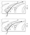
- FIG. 8 is an illustration of a streamline of cooling fluid in a pre-swirler without features disclosed herein.
- FIG. 9 is an illustration of a streamline of cooling fluid in a pre-swirler having the features disclosed herein.
- the present inventors have devised a pre-swirler for an ambient-air induced-cooling arrangement for cooling turbine blades in a gas turbine engine, where the pre-swirler has contoured end walls to improve flow characteristics exhibited by a flow of cooling fluid flowing through the pre-swirler.
- the pre-swirler induces a swirl to a flow of ambient air before the flow is introduced to the rotating turbine blades, thereby providing a more efficient delivery of the flow of cooling fluid to inlets of cooling channels in the blades.
- the contoured end walls reduce a pressure loss in the flow, thereby increasing efficiency of the flow through the pre-swirler which, in turn, increases an efficiency of the gas turbine engine.
- FIG. 1 shows a schematic cross section of a side view of a portion of an exemplary embodiment of an ambient air cooling circuit 10 , including: a source 12 of ambient air; at least one air supply passage 14 providing fluid communication between the source 12 and a pre-swirler plenum 16 , and optionally being disposed in a strut 17 that supports a pre-swirler 18 ; a rotor cavity 20 adjacent to turbine blades 22 ; and a cooling channel inlet (not shown), a cooling channel 26 , and a cooling channel outlet 29 in each of the turbine blades 22 , which may or may not be disposed at a tip of the turbine blade 22 .
- the ambient air becomes cooling fluid 28 .
- the cooling fluid 28 travels through the air supply passage 14 where it enters the pre-swirler plenum 16 , which is an annular shaped plenum that supplies the cooling fluid 28 to the pre-swirler 18 .
- the pre-swirler 18 the cooling fluid 28 is swirled about a longitudinal axis 30 of the rotor disc 31 .
- the cooling fluid 28 enters the cooling channel inlets, for example, either directly from the pre-swirler 18 or after the cooling fluid 28 travels through a gap between a rotor disc 31 and base of the turbine blade 22 , and then the cooling fluid 28 travels through each cooling channel 26 .
- a rotation of the turbine blades 22 about the longitudinal axis 30 of the rotor disc 31 creates a centrifugal force in a radially outward direction 32 that motivates the cooling fluid 28 through the cooling channels 26 .
- the cooling fluid 28 is ejected from the cooling channel outlet 29 and into a hot gas path 34 in which hot gases 36 flow.
- the movement of the cooling fluid 28 through the cooling channels 26 and out the cooling channel outlet 29 creates a suction force that draws cooling fluid 28 from the rotor cavity 20 into the cooling channel 26 to replace the cooling fluid 28 that has been ejected.
- a static pressure of ambient air pushes cooling fluid 28 toward the rotor cavity 20 to replace cooling fluid 28 that is drawn into the cooling channels 26 , thereby completing the ambient air cooling circuit 10 .
- FIG. 2 is a schematic perspective view of the pre-swirler 18 of the ambient air cooling circuit 10 , from an aft end of the gas turbine engine, with an outer shroud removed. Visible are an inner shroud 38 having a constant diameter 40 and a plurality of guide vanes 42 disposed in an annular array about a longitudinal axis 30 of the rotor disc 31 .
- the pre-swirler 18 receives an axially flowing, annular shaped flow of cooling fluid 28 delivered by the pre-swirler plenum 16 and imparts circumferential motion resulting in a swirl about the longitudinal axis 30 of the rotor disc 31 . As can be seen in FIG.
- the plurality of guide vanes 42 define a plurality of nozzles 44 that guide the cooling fluid 28 , each nozzle 44 being formed between and defined by a first guide vane 46 ; a circumferentially adjacent guide vane 48 ; an outer end wall 50 of an inner shroud 38 , and an inner end wall 54 of an outer shroud 56 which the guide vanes 42 span.
- Each nozzle 44 therefore defines part of the cooling circuit 10 .
- the end walls disclosed herein do not have a constant diameter 40 . Instead, the end walls are contoured in both a circumferential direction 60 and an axial direction 62 and may undulate about the constant diameter 40 .
- a horseshoe vortex 70 that may develop at an intersection 72 of a leading edge 74 of the guide vane 42 and an end wall. Within a nozzle 44 these vortices tend to develop in relatively slower regions of a flow of fluid where there is relatively higher static pressure. Cooling fluid near to the end walls and a pressure side 76 and/or a suction side 78 is slowed relative to other regions within the cooling fluid 28 by various aerodynamic factors, including friction associated with these surfaces. As a result, cooling fluid 28 in a region 80 proximate the intersections 72 may be relatively slow moving when compared to a central regions 82 within the nozzle 44 .
- cooling fluid 28 encountering the leading edge 74 of the guide vane 42 causes a bow wave in front of the leading edge 74 where higher static pressure builds when compared to static pressure within other regions in the flow. Consequently, both relatively slow moving fluid and a relatively high static pressure exist in the region 80 proximate the intersections 72 when compared to the central regions 82 within the nozzle 44 . Since the strength of a horseshoe vortex is related to a magnitude of a velocity gradient between the two regions and a magnitude of a static pressure gradient between the two regions, relatively strong horseshoe vortices 70 may develop in a nozzle 44 of the type disclosed herein. The losses associated with horseshoe vortices are magnified when guide vanes have a low aspect ratio.
- a shorter radial height and a longer length of the airfoil give the horseshoe vortex more opportunity to move closer to the central region 82 . Consequently, the benefit of having contoured end walls ( 50 , 54 ) in an exemplary embodiment of the pre-swirler 18 having low aspect ratio guide vanes 42 is also pronounced.
- cooling fluid 28 in a relatively faster moving region of a flow will tend to draw a leg 84 of the horseshoe vortex 70 toward the relatively faster moving region as the leg 84 flows downstream.
- the leg 84 of a radially inner horseshoe vortex 86 may be drawn in a radially outward direction 32 . Drawing the leg 84 into the central region 82 within the nozzle 44 creates a greater amount of aerodynamic loss in the flow than would occur if the leg 84 were to remain in the region 80 proximate the intersections 72 where the flow rate is lower, and hence aerodynamic losses in the region are less problematic.
- the end walls disclosed herein are effective to reduce the velocity gradient and/or the static pressure gradient, which reduces the strength of the horseshoe vortex 70 .
- the end wall geometry helps the leg 84 of the horseshoe vortex 70 remain closer to the region 80 proximate the intersections 72 , thereby mitigating aerodynamic losses within the central region 82 within the nozzle 44 .
- the contouring includes a hump 100 , also seen as a raised area, on each end wall abutting the pressure side 76 of the guide vane 42 .
- the hump 100 disclosed herein is a region where the end wall projects farther into a nozzle when compared to an end wall without a hump 100 .
- the contouring further includes a valley 102 , or recessed area, on each end wall between the guide vanes 42 .
- the valley 102 disclosed herein is a region where the end wall recedes from a nozzle when compared to an end wall without a valley 102 . Any region of a nozzle end wall without a hump 100 or a valley 102 may be considered a constant diameter region.
- Each end wall may have a respective constant diameter region, i.e.
- each end wall may have a hump 100 or valley 102 that occupies only a small portion of the respective end wall, or each end wall may be entirely defined by the hump 100 and valley 102 , leaving no actual constant diameter (i.e. neutral) region.
- the hump 100 work together to cause the cooling fluid 28 in the region 80 proximate the intersections 72 to flow faster than if there were no hump 100 by decreasing a cross sectional area of the nozzle 44 in the region 80 proximate the intersections 72 . With less area in which to flow, the cooling fluid 28 must necessarily speed up. It is also believed that the valleys 102 work together to cause the cooling fluid 28 in the central region 82 within the nozzle 44 to slow down due to the increased cross sectional area of the nozzle 44 .
- a static pressure in the region 80 proximate the intersections 72 is relatively high due to the slow velocity of the cooling fluid 28 .
- the static pressure decreases.
- valleys 102 a static pressure in the central region 82 within the nozzle 44 is relatively low due to the high velocity of the cooling fluid 28 .
- the static pressure increases. Decreasing a relatively high static pressure in the region 80 proximate the intersections 72 , and increasing the relatively low static pressure in the central region 82 within the nozzle 44 yields a smaller pressure gradient which, in turn, yields a weaker horseshoe vortex 70 .
- FIG. 4 is a cutaway view of the pre-swirler 18 of FIG. 3 , showing a radially inward portion of the guide vanes 42 and the inner shroud 38 , with a radially outward portion of the guide vanes 42 and the outer shroud 56 removed.
- a radially inward portion of a plurality of nozzles 44 is shown, each being defined in part by the outer end wall 50 of the inner shroud 38 , a pressure side 76 of a first guide vane 46 and a suction side 78 of the circumferentially adjacent guide vane 48 .
- Cooling fluid 28 enters an inlet end 110 of the nozzle 44 while traveling primarily in an axial direction with respect to the longitudinal axis 30 of the rotor disc 31 , and exits from an outlet end 112 traveling in a direction of travel having a component in the axial direction and a component in the circumferential direction 60 .
- the inner shroud 38 and/or the outer shroud 56 can be a monolithic body.
- Vane assemblies used to guide combustion gases in turbines are conventionally made of subcomponents that are assembled into a ring of vanes. Such a configuration is necessary due to factors associated with the larger size of these vane rings, including a high cost to manufacture a single body of this size, thermal growth problems, and assembly and disassembly of the turbine itself which often necessitates disassembling the vane ring.
- These assembled vane rings often have joints between the subcomponents that change throughout operation. For example, there may be no circumferential gap in the nozzle between adjacent subcomponents, or there may be a circumferential gap. This alone provides for varying aerodynamics.
- the joint may or may not be radially aligned.
- one subcomponent may extend radially further out than another.
- the gases may encounter a step. It may be a step up or a step down, depending on whether the first subcomponent extends radially farther outward than the adjacent subcomponent, or does not extend radially as far. Both types of steps create vortices in the flow, and these vortices create the same type of aerodynamic losses that the horseshoe vortices 70 do.
- the inner shroud 38 and the outer shroud 56 do not suffer from the foregoing limitations and therefore they can be manufactured as a single piece component. Having a single piece/monolithic construction allows the nozzles to avoid the aerodynamic losses associated with joints between assembled subcomponents. This, in turn, leads to lower pressure loss resulting from travel through the nozzle 44 .
- FIG. 5 is a cutaway view of the pre-swirler 18 of FIG. 3 , showing a radially outward portion of the guide vanes 42 and the outer shroud 56 , with a radially inward portion of the guide vanes 42 and the inner shroud 38 removed.
- a radially outward portion of a plurality of nozzles 44 is shown, each being defined in part by the inner end wall 54 of an outer shroud 56 , a pressure side 76 of a first guide vane 46 and a suction side 78 of the circumferentially adjacent guide vane 48 .
- FIG. 6 is a top view showing a topography of an exemplary embodiment of the inner shroud 38 of the pre-swirler 18 .
- the hump 100 is visible adjacent to the pressure side 76 of the first guide vane 46 and a peak of the hump 100 may be disposed approximate one third of the way down a chord line 122 from the leading edge 74 of the first guide vane to a trailing edge 126 .
- the valley 102 is visible in a circumferential direction 60 approximately half way between the first guide vane 46 and the circumferentially adjacent guide vane 48 .
- Horseshoe vortex 70 is visible emanating from the leading edge 74 of the first guide vane 46 .
- a lowest point 120 of the valley is disposed approximately two thirds of the way down the chord line 122 from the leading edge 74 of the first guide vane to the trailing edge 126 . It is also located downstream of the leg 84 of the horseshoe vortex 70 such that the leg 84 is forced to travel over (as seen in FIG. 6 ) the valley 102 .
- FIG. 7 is a view showing a topography of an exemplary embodiment of the outer shroud 56 of the pre-swirler 18 , as though looking radially inward at a mirror placed on the hub under the outer shroud 56 . Since the outer shroud 56 is radially farther outward it is longer, and therefore there is more space between adjacent guide vanes 42 . By eliminating this extra length to match the size of FIG. 6 the hump 100 and valleys 102 appear smaller, but may actually be not smaller.
- the humps 100 and valleys 102 shown are exemplary. Any contour that produces the desired aerodynamic affects is considered to be within the scope of the disclosure.
- FIG. 8 is an illustration of a streamline of the cooling fluid 28 in a pre-swirler without features disclosed herein using fluid modeling.
- Streamline 124 represents leg 84 of horseshoe vortex 70 . It can be seen that upon encountering the leading edge 74 of the first guide vane 46 leg 84 begins to separate from the pressure side of the first guide vane 46 . As it traverses the nozzle 44 the streamline 124 migrates toward the suction side 78 of the circumferentially adjacent guide vane 48 toward the trailing edge 126 of the circumferentially adjacent guide vane 48 . While doing this the streamline 124 is also moving upward, out of a plane of the paper, toward the central region 82 within the nozzle 44 , and causing aerodynamic losses.
- FIG. 9 is an illustration of a streamline of the cooling fluid 28 in a pre-swirler 18 having the features disclosed herein using fluid modeling.
- the streamline 124 of the leg 84 of the horseshoe vortex 70 departs slightly from the pressure side 76 .
- the streamline 124 does not migrate toward the suction side 78 of the circumferentially adjacent guide vane 48 as it travels within the nozzle 44 toward the trailing edge 126 of the circumferentially adjacent guide vane 48 .
- the streamline 124 adheres to the pressure side 76 of the first guide vane 46 for a longer distance.
- the streamline 124 is less likely to depart from the plane of the paper to the same degree.
- the leg 84 of the horseshoe vortex 70 generates less aerodynamic loss, yielding more efficient operation of the gas turbine engine.
Abstract
Description
Claims (18)
Priority Applications (7)
| Application Number | Priority Date | Filing Date | Title |
|---|---|---|---|
| US13/766,909 US8926267B2 (en) | 2011-04-12 | 2013-02-14 | Ambient air cooling arrangement having a pre-swirler for gas turbine engine blade cooling |
| PCT/US2014/016014 WO2014126994A1 (en) | 2013-02-14 | 2014-02-12 | Gas turbine engine with an ambient air cooling arrangement having a pre-swirler |
| RU2015134151A RU2618153C2 (en) | 2013-02-14 | 2014-02-12 | Gas turbine engine with ambient air cooling device comprising preliminary swirler |
| EP14706248.3A EP2956624B1 (en) | 2013-02-14 | 2014-02-12 | Gas turbine engine with an ambient air cooling arrangement having a pre-swirler |
| CN201480008673.XA CN105392964B (en) | 2013-02-14 | 2014-02-12 | Gas-turbine unit with the surrounding air cooling arrangement for having preswirl device |
| JP2015558100A JP6173489B2 (en) | 2013-02-14 | 2014-02-12 | Gas turbine engine with ambient air cooling system with pre-turning vanes |
| SA515360813A SA515360813B1 (en) | 2013-02-14 | 2015-07-27 | Ambient air cooling arrangement having a pre-swirler for gas turbine engine blade cooling |
Applications Claiming Priority (2)
| Application Number | Priority Date | Filing Date | Title |
|---|---|---|---|
| US13/084,618 US8684666B2 (en) | 2011-04-12 | 2011-04-12 | Low pressure cooling seal system for a gas turbine engine |
| US13/766,909 US8926267B2 (en) | 2011-04-12 | 2013-02-14 | Ambient air cooling arrangement having a pre-swirler for gas turbine engine blade cooling |
Related Parent Applications (1)
| Application Number | Title | Priority Date | Filing Date |
|---|---|---|---|
| US13/084,618 Continuation-In-Part US8684666B2 (en) | 2011-04-12 | 2011-04-12 | Low pressure cooling seal system for a gas turbine engine |
Publications (2)
| Publication Number | Publication Date |
|---|---|
| US20130156579A1 US20130156579A1 (en) | 2013-06-20 |
| US8926267B2 true US8926267B2 (en) | 2015-01-06 |
Family
ID=48610316
Family Applications (1)
| Application Number | Title | Priority Date | Filing Date |
|---|---|---|---|
| US13/766,909 Active 2031-06-04 US8926267B2 (en) | 2011-04-12 | 2013-02-14 | Ambient air cooling arrangement having a pre-swirler for gas turbine engine blade cooling |
Country Status (1)
| Country | Link |
|---|---|
| US (1) | US8926267B2 (en) |
Cited By (6)
| Publication number | Priority date | Publication date | Assignee | Title |
|---|---|---|---|---|
| US20170074106A1 (en) * | 2015-09-16 | 2017-03-16 | General Electric Company | Mixing chambers for turbine wheel space cooling |
| US20180298774A1 (en) * | 2017-04-18 | 2018-10-18 | United Technologies Corporation | Forward facing tangential onboard injectors for gas turbine engines |
| US11028708B2 (en) * | 2017-04-26 | 2021-06-08 | Aecc Commercial Aircraft Engine Co., Ltd. | Blade profile tube nozzle for gas turbine |
| US11466579B2 (en) * | 2016-12-21 | 2022-10-11 | General Electric Company | Turbine engine airfoil and method |
| US11719440B2 (en) * | 2018-12-19 | 2023-08-08 | Doosan Enerbility Co., Ltd. | Pre-swirler having dimples |
| US11939880B1 (en) | 2022-11-03 | 2024-03-26 | General Electric Company | Airfoil assembly with flow surface |
Families Citing this family (7)
| Publication number | Priority date | Publication date | Assignee | Title |
|---|---|---|---|---|
| US9359902B2 (en) | 2013-06-28 | 2016-06-07 | Siemens Energy, Inc. | Turbine airfoil with ambient cooling system |
| DE102013011350A1 (en) * | 2013-07-08 | 2015-01-22 | Rolls-Royce Deutschland Ltd & Co Kg | Gas turbine with high pressure turbine cooling system |
| US9822662B2 (en) | 2013-11-08 | 2017-11-21 | Siemens Energy, Inc. | Cooling system with compressor bleed and ambient air for gas turbine engine |
| US20160290645A1 (en) | 2013-11-21 | 2016-10-06 | United Technologies Corporation | Axisymmetric offset of three-dimensional contoured endwalls |
| US9995171B2 (en) * | 2015-01-16 | 2018-06-12 | United Technologies Corporation | Cooling passages for a mid-turbine frame |
| CN105114186B (en) * | 2015-08-04 | 2017-03-29 | 西北工业大学 | A kind of leaf cellular type preswirl nozzle for cooling system of prewhirling |
| US10196903B2 (en) * | 2016-01-15 | 2019-02-05 | General Electric Company | Rotor blade cooling circuit |
Citations (35)
| Publication number | Priority date | Publication date | Assignee | Title |
|---|---|---|---|---|
| US2735612A (en) | 1956-02-21 | hausmann | ||
| US2918254A (en) | 1954-05-10 | 1959-12-22 | Hausammann Werner | Turborunner |
| US4236869A (en) | 1977-12-27 | 1980-12-02 | United Technologies Corporation | Gas turbine engine having bleed apparatus with dynamic pressure recovery |
| US4420288A (en) | 1980-06-24 | 1983-12-13 | Mtu Motoren- Und Turbinen-Union Gmbh | Device for the reduction of secondary losses in a bladed flow duct |
| US4677828A (en) | 1983-06-16 | 1987-07-07 | United Technologies Corporation | Circumferentially area ruled duct |
| US4759688A (en) | 1986-12-16 | 1988-07-26 | Allied-Signal Inc. | Cooling flow side entry for cooled turbine blading |
| US4807433A (en) | 1983-05-05 | 1989-02-28 | General Electric Company | Turbine cooling air modulation |
| US5311734A (en) | 1991-09-11 | 1994-05-17 | General Electric Company | System and method for improved engine cooling in conjunction with an improved gas bearing face seal assembly |
| US5397215A (en) | 1993-06-14 | 1995-03-14 | United Technologies Corporation | Flow directing assembly for the compression section of a rotary machine |
| US5466123A (en) | 1993-08-20 | 1995-11-14 | Rolls-Royce Plc | Gas turbine engine turbine |
| US5575616A (en) | 1994-10-11 | 1996-11-19 | General Electric Company | Turbine cooling flow modulation apparatus |
| US6427448B1 (en) * | 1998-06-03 | 2002-08-06 | Siemens Aktiengesellschaft | Gas turbine and method of cooling a turbine stage |
| US6554569B2 (en) | 2001-08-17 | 2003-04-29 | General Electric Company | Compressor outlet guide vane and diffuser assembly |
| US6561761B1 (en) | 2000-02-18 | 2003-05-13 | General Electric Company | Fluted compressor flowpath |
| US6669445B2 (en) | 2002-03-07 | 2003-12-30 | United Technologies Corporation | Endwall shape for use in turbomachinery |
| US6969232B2 (en) | 2002-10-23 | 2005-11-29 | United Technologies Corporation | Flow directing device |
| US20060140768A1 (en) | 2004-12-24 | 2006-06-29 | General Electric Company | Scalloped surface turbine stage |
| US7220100B2 (en) | 2005-04-14 | 2007-05-22 | General Electric Company | Crescentic ramp turbine stage |
| US7354243B2 (en) | 2005-09-13 | 2008-04-08 | Rolls-Royce, Plc | Axial compressor blading |
| US20080277944A1 (en) | 2007-05-09 | 2008-11-13 | United Technologies Corporation | Aircraft combination engines complemental connection and operation |
| US7465155B2 (en) | 2006-02-27 | 2008-12-16 | Honeywell International Inc. | Non-axisymmetric end wall contouring for a turbomachine blade row |
| US7503748B2 (en) | 2004-03-13 | 2009-03-17 | Rolls-Royce, Plc | Mounting arrangement for turbine blades |
| US20090162193A1 (en) | 2007-12-19 | 2009-06-25 | Massimiliano Mariotti | Turbine inlet guide vane with scalloped platform and related method |
| US20100000219A1 (en) * | 2008-07-02 | 2010-01-07 | General Electric Company | Systems and Methods for Supplying Cooling Air to a Gas Turbine |
| US7677048B1 (en) | 2006-05-24 | 2010-03-16 | Florida Turbine Technologies, Inc. | Turbine last stage blade with forced vortex driven cooling air |
| US7690890B2 (en) | 2004-09-24 | 2010-04-06 | Ishikawajima-Harima Heavy Industries Co. Ltd. | Wall configuration of axial-flow machine, and gas turbine engine |
| US20100166549A1 (en) | 2008-12-30 | 2010-07-01 | General Electric Company | Methods, systems and/or apparatus relating to inducers for turbine engines |
| US7811049B2 (en) | 2004-04-13 | 2010-10-12 | Rolls-Royce, Plc | Flow control arrangement |
| US7874794B2 (en) | 2006-03-21 | 2011-01-25 | General Electric Company | Blade row for a rotary machine and method of fabricating same |
| US7887297B2 (en) | 2006-05-02 | 2011-02-15 | United Technologies Corporation | Airfoil array with an endwall protrusion and components of the array |
| US20110236200A1 (en) | 2010-03-23 | 2011-09-29 | Grover Eric A | Gas turbine engine with non-axisymmetric surface contoured vane platform |
| US20110247346A1 (en) | 2010-04-12 | 2011-10-13 | Kimmel Keith D | Cooling fluid metering structure in a gas turbine engine |
| EP2423437A2 (en) | 2010-08-31 | 2012-02-29 | General Electric Company | Turbine assembly with end-wall-contoured airfoils and preferential clocking |
| US20120263575A1 (en) | 2011-04-12 | 2012-10-18 | Marra John J | Low pressure cooling seal system for a gas turbine engine |
| US8641362B1 (en) * | 2011-09-13 | 2014-02-04 | Florida Turbine Technologies, Inc. | Turbine exhaust cylinder and strut cooling |
-
2013
- 2013-02-14 US US13/766,909 patent/US8926267B2/en active Active
Patent Citations (35)
| Publication number | Priority date | Publication date | Assignee | Title |
|---|---|---|---|---|
| US2735612A (en) | 1956-02-21 | hausmann | ||
| US2918254A (en) | 1954-05-10 | 1959-12-22 | Hausammann Werner | Turborunner |
| US4236869A (en) | 1977-12-27 | 1980-12-02 | United Technologies Corporation | Gas turbine engine having bleed apparatus with dynamic pressure recovery |
| US4420288A (en) | 1980-06-24 | 1983-12-13 | Mtu Motoren- Und Turbinen-Union Gmbh | Device for the reduction of secondary losses in a bladed flow duct |
| US4807433A (en) | 1983-05-05 | 1989-02-28 | General Electric Company | Turbine cooling air modulation |
| US4677828A (en) | 1983-06-16 | 1987-07-07 | United Technologies Corporation | Circumferentially area ruled duct |
| US4759688A (en) | 1986-12-16 | 1988-07-26 | Allied-Signal Inc. | Cooling flow side entry for cooled turbine blading |
| US5311734A (en) | 1991-09-11 | 1994-05-17 | General Electric Company | System and method for improved engine cooling in conjunction with an improved gas bearing face seal assembly |
| US5397215A (en) | 1993-06-14 | 1995-03-14 | United Technologies Corporation | Flow directing assembly for the compression section of a rotary machine |
| US5466123A (en) | 1993-08-20 | 1995-11-14 | Rolls-Royce Plc | Gas turbine engine turbine |
| US5575616A (en) | 1994-10-11 | 1996-11-19 | General Electric Company | Turbine cooling flow modulation apparatus |
| US6427448B1 (en) * | 1998-06-03 | 2002-08-06 | Siemens Aktiengesellschaft | Gas turbine and method of cooling a turbine stage |
| US6561761B1 (en) | 2000-02-18 | 2003-05-13 | General Electric Company | Fluted compressor flowpath |
| US6554569B2 (en) | 2001-08-17 | 2003-04-29 | General Electric Company | Compressor outlet guide vane and diffuser assembly |
| US6669445B2 (en) | 2002-03-07 | 2003-12-30 | United Technologies Corporation | Endwall shape for use in turbomachinery |
| US6969232B2 (en) | 2002-10-23 | 2005-11-29 | United Technologies Corporation | Flow directing device |
| US7503748B2 (en) | 2004-03-13 | 2009-03-17 | Rolls-Royce, Plc | Mounting arrangement for turbine blades |
| US7811049B2 (en) | 2004-04-13 | 2010-10-12 | Rolls-Royce, Plc | Flow control arrangement |
| US7690890B2 (en) | 2004-09-24 | 2010-04-06 | Ishikawajima-Harima Heavy Industries Co. Ltd. | Wall configuration of axial-flow machine, and gas turbine engine |
| US20060140768A1 (en) | 2004-12-24 | 2006-06-29 | General Electric Company | Scalloped surface turbine stage |
| US7220100B2 (en) | 2005-04-14 | 2007-05-22 | General Electric Company | Crescentic ramp turbine stage |
| US7354243B2 (en) | 2005-09-13 | 2008-04-08 | Rolls-Royce, Plc | Axial compressor blading |
| US7465155B2 (en) | 2006-02-27 | 2008-12-16 | Honeywell International Inc. | Non-axisymmetric end wall contouring for a turbomachine blade row |
| US7874794B2 (en) | 2006-03-21 | 2011-01-25 | General Electric Company | Blade row for a rotary machine and method of fabricating same |
| US7887297B2 (en) | 2006-05-02 | 2011-02-15 | United Technologies Corporation | Airfoil array with an endwall protrusion and components of the array |
| US7677048B1 (en) | 2006-05-24 | 2010-03-16 | Florida Turbine Technologies, Inc. | Turbine last stage blade with forced vortex driven cooling air |
| US20080277944A1 (en) | 2007-05-09 | 2008-11-13 | United Technologies Corporation | Aircraft combination engines complemental connection and operation |
| US20090162193A1 (en) | 2007-12-19 | 2009-06-25 | Massimiliano Mariotti | Turbine inlet guide vane with scalloped platform and related method |
| US20100000219A1 (en) * | 2008-07-02 | 2010-01-07 | General Electric Company | Systems and Methods for Supplying Cooling Air to a Gas Turbine |
| US20100166549A1 (en) | 2008-12-30 | 2010-07-01 | General Electric Company | Methods, systems and/or apparatus relating to inducers for turbine engines |
| US20110236200A1 (en) | 2010-03-23 | 2011-09-29 | Grover Eric A | Gas turbine engine with non-axisymmetric surface contoured vane platform |
| US20110247346A1 (en) | 2010-04-12 | 2011-10-13 | Kimmel Keith D | Cooling fluid metering structure in a gas turbine engine |
| EP2423437A2 (en) | 2010-08-31 | 2012-02-29 | General Electric Company | Turbine assembly with end-wall-contoured airfoils and preferential clocking |
| US20120263575A1 (en) | 2011-04-12 | 2012-10-18 | Marra John J | Low pressure cooling seal system for a gas turbine engine |
| US8641362B1 (en) * | 2011-09-13 | 2014-02-04 | Florida Turbine Technologies, Inc. | Turbine exhaust cylinder and strut cooling |
Cited By (8)
| Publication number | Priority date | Publication date | Assignee | Title |
|---|---|---|---|---|
| US20170074106A1 (en) * | 2015-09-16 | 2017-03-16 | General Electric Company | Mixing chambers for turbine wheel space cooling |
| US9970299B2 (en) * | 2015-09-16 | 2018-05-15 | General Electric Company | Mixing chambers for turbine wheel space cooling |
| US11466579B2 (en) * | 2016-12-21 | 2022-10-11 | General Electric Company | Turbine engine airfoil and method |
| US20180298774A1 (en) * | 2017-04-18 | 2018-10-18 | United Technologies Corporation | Forward facing tangential onboard injectors for gas turbine engines |
| US10458266B2 (en) * | 2017-04-18 | 2019-10-29 | United Technologies Corporation | Forward facing tangential onboard injectors for gas turbine engines |
| US11028708B2 (en) * | 2017-04-26 | 2021-06-08 | Aecc Commercial Aircraft Engine Co., Ltd. | Blade profile tube nozzle for gas turbine |
| US11719440B2 (en) * | 2018-12-19 | 2023-08-08 | Doosan Enerbility Co., Ltd. | Pre-swirler having dimples |
| US11939880B1 (en) | 2022-11-03 | 2024-03-26 | General Electric Company | Airfoil assembly with flow surface |
Also Published As
| Publication number | Publication date |
|---|---|
| US20130156579A1 (en) | 2013-06-20 |
Similar Documents
| Publication | Publication Date | Title |
|---|---|---|
| US8926267B2 (en) | Ambient air cooling arrangement having a pre-swirler for gas turbine engine blade cooling | |
| EP2956624B1 (en) | Gas turbine engine with an ambient air cooling arrangement having a pre-swirler | |
| CN107448300B (en) | Airfoil for a turbine engine | |
| JP6060145B2 (en) | High camber compressor rotor blade | |
| US10458427B2 (en) | Compressor aerofoil | |
| US10577955B2 (en) | Airfoil assembly with a scalloped flow surface | |
| US20100166558A1 (en) | Methods and apparatus relating to improved turbine blade platform contours | |
| US9518467B2 (en) | Blade with 3D platform comprising an inter-blade bulb | |
| US9726024B2 (en) | Airfoil cooling circuit | |
| US20130315710A1 (en) | Gas turbine engine components with cooling hole trenches | |
| US10815806B2 (en) | Engine component with insert | |
| US10830057B2 (en) | Airfoil with tip rail cooling | |
| CN104246138A (en) | Turbine airfoil with local wall thickness control | |
| US10577943B2 (en) | Turbine engine airfoil insert | |
| US20170298743A1 (en) | Component for a turbine engine with a film-hole | |
| EP2960434A1 (en) | Compressor aerofoil and corresponding compressor rotor assembly | |
| US10450874B2 (en) | Airfoil for a gas turbine engine | |
| US20220356805A1 (en) | Airfoil assembly with a fluid circuit | |
| US9528706B2 (en) | Swirling midframe flow for gas turbine engine having advanced transitions | |
| US20180291743A1 (en) | Turbine engine airfoil having a cooling circuit | |
| US10837291B2 (en) | Turbine engine with component having a cooled tip | |
| JP2017129138A (en) | Turbine rear frame for turbine engine | |
| US11959393B2 (en) | Turbine engine with reduced cross flow airfoils | |
| CN110735664A (en) | Component for a turbine engine having cooling holes | |
| US11242770B2 (en) | Turbine center frame and method |
Legal Events
| Date | Code | Title | Description |
|---|---|---|---|
| AS | Assignment |
Owner name: QUEST ASE INC., OHIO Free format text: ASSIGNMENT OF ASSIGNORS INTEREST;ASSIGNORS:SCHROEDER, ERIC;MEEROFF, JAMIE;REEL/FRAME:029811/0568 Effective date: 20121212 Owner name: SIEMENS ENERGY, INC, FLORIDA Free format text: ASSIGNMENT OF ASSIGNORS INTEREST;ASSIGNORS:LEE, CHING-PANG;THAM, KOK-MUN;MILLER, SAMUEL R., JR.;AND OTHERS;SIGNING DATES FROM 20121211 TO 20130104;REEL/FRAME:029811/0445 |
|
| AS | Assignment |
Owner name: SIEMENS ENERGY, INC., FLORIDA Free format text: ASSIGNMENT OF ASSIGNORS INTEREST;ASSIGNOR:QUEST ASE INC.;REEL/FRAME:030235/0175 Effective date: 20130417 |
|
| AS | Assignment |
Owner name: ENERGY, UNITED STATES DEPARTMENT OF, DISTRICT OF C Free format text: CONFIRMATORY LICENSE;ASSIGNOR:SIEMENS ENERGY, INC.;REEL/FRAME:030399/0672 Effective date: 20130329 |
|
| AS | Assignment |
Owner name: ENERGY, UNITED STATES DEPARTMENT OF, DISTRICT OF C Free format text: CONFIRMATORY LICENSE;ASSIGNOR:SIEMENS ENERGY, INC.;REEL/FRAME:030613/0305 Effective date: 20130329 |
|
| STCF | Information on status: patent grant |
Free format text: PATENTED CASE |
|
| MAFP | Maintenance fee payment |
Free format text: PAYMENT OF MAINTENANCE FEE, 4TH YEAR, LARGE ENTITY (ORIGINAL EVENT CODE: M1551) Year of fee payment: 4 |
|
| MAFP | Maintenance fee payment |
Free format text: PAYMENT OF MAINTENANCE FEE, 8TH YEAR, LARGE ENTITY (ORIGINAL EVENT CODE: M1552); ENTITY STATUS OF PATENT OWNER: LARGE ENTITY Year of fee payment: 8 |