US8925646B2 - Right angle impact tool - Google Patents
Right angle impact tool Download PDFInfo
- Publication number
- US8925646B2 US8925646B2 US13/033,241 US201113033241A US8925646B2 US 8925646 B2 US8925646 B2 US 8925646B2 US 201113033241 A US201113033241 A US 201113033241A US 8925646 B2 US8925646 B2 US 8925646B2
- Authority
- US
- United States
- Prior art keywords
- axis
- spur gear
- rotation
- output
- impact
- Prior art date
- Legal status (The legal status is an assumption and is not a legal conclusion. Google has not performed a legal analysis and makes no representation as to the accuracy of the status listed.)
- Active, expires
Links
Images


Classifications
-
- B—PERFORMING OPERATIONS; TRANSPORTING
- B25—HAND TOOLS; PORTABLE POWER-DRIVEN TOOLS; MANIPULATORS
- B25B—TOOLS OR BENCH DEVICES NOT OTHERWISE PROVIDED FOR, FOR FASTENING, CONNECTING, DISENGAGING OR HOLDING
- B25B21/00—Portable power-driven screw or nut setting or loosening tools; Attachments for drilling apparatus serving the same purpose
- B25B21/02—Portable power-driven screw or nut setting or loosening tools; Attachments for drilling apparatus serving the same purpose with means for imparting impact to screwdriver blade or nut socket
- B25B21/026—Impact clutches
-
- B—PERFORMING OPERATIONS; TRANSPORTING
- B25—HAND TOOLS; PORTABLE POWER-DRIVEN TOOLS; MANIPULATORS
- B25F—COMBINATION OR MULTI-PURPOSE TOOLS NOT OTHERWISE PROVIDED FOR; DETAILS OR COMPONENTS OF PORTABLE POWER-DRIVEN TOOLS NOT PARTICULARLY RELATED TO THE OPERATIONS PERFORMED AND NOT OTHERWISE PROVIDED FOR
- B25F5/00—Details or components of portable power-driven tools not particularly related to the operations performed and not otherwise provided for
- B25F5/02—Construction of casings, bodies or handles
-
- B—PERFORMING OPERATIONS; TRANSPORTING
- B25—HAND TOOLS; PORTABLE POWER-DRIVEN TOOLS; MANIPULATORS
- B25B—TOOLS OR BENCH DEVICES NOT OTHERWISE PROVIDED FOR, FOR FASTENING, CONNECTING, DISENGAGING OR HOLDING
- B25B21/00—Portable power-driven screw or nut setting or loosening tools; Attachments for drilling apparatus serving the same purpose
- B25B21/02—Portable power-driven screw or nut setting or loosening tools; Attachments for drilling apparatus serving the same purpose with means for imparting impact to screwdriver blade or nut socket
- B25B21/023—Portable power-driven screw or nut setting or loosening tools; Attachments for drilling apparatus serving the same purpose with means for imparting impact to screwdriver blade or nut socket for imparting an axial impact, e.g. for self-tapping screws
Definitions
- the present invention relates to gear arrangements for angle impact tools.
- the invention provides an angle impact tool including a handle assembly extending along a first axis and graspable by a user.
- a prime mover is positioned in the handle and includes an output shaft rotatable about the first axis.
- a work attachment is connected to the handle assembly.
- An output drive is supported in the work attachment for rotation about an output axis perpendicular to the first axis.
- a gear assembly is positioned within the work attachment.
- the gear assembly includes at least one spur gear and is operable to transfer torque from the prime mover about the first axis to the output drive about the output axis.
- An impact mechanism is positioned within the work attachment.
- the impact mechanism includes a hammer and an anvil. The hammer rotates under the influence of the prime mover and is operable to periodically deliver an impact load to the anvil.
- the output drive rotates about the output axis under the influence of the impact load being transmitted to the output drive by the anvil.
- the invention provides an angle impact tool including a handle assembly graspable by a user, and a prime mover at least partially contained within the handle assembly.
- the prime mover has a rotor rotatable about a first axis.
- An output drive is functionally coupled to the prime mover and selectively rotated in response to rotation of the rotor.
- the output drive defines an output axis about which the output drive rotates.
- the output axis is substantially perpendicular to the first axis.
- At least one bevel gear is functionally positioned between the rotor and the output drive.
- the at least one bevel gear is rotatable in response to rotation of the rotor.
- At least one spur gear is functionally positioned between the rotor and the output drive.
- the at least one spur gear is rotatable in response to rotation of the rotor.
- An impact mechanism is functionally positioned between the prime mover and the output drive. The impact mechanism selectively drives the output drive with impact forces in response to rotation
- the invention provides an angle impact tool including a handle assembly extending generally along a first axis and graspable by a user, a prime mover having an output shaft rotatable about the first axis, and an output drive functionally coupled to the prime mover and selectively rotated in response to rotation of the output shaft.
- the output drive defines an output axis about which the output drive rotates.
- the output axis is substantially perpendicular to the first axis.
- a first spur gear is functionally positioned between the prime mover and the impact mechanism. The first spur gear is rotatable in response to rotation of the output shaft.
- a second spur gear meshes with the first spur gear for rotation in response to rotation of the first spur gear.
- a third spur gear meshes with the second spur gear for rotation in response to rotation of the first and second spur gears.
- a first bevel gear is connected to the output shaft for rotation with the output shaft about the first axis.
- a second bevel gear is functionally positioned between the first bevel gear and the first spur gear, such that rotation of the first bevel gear about the first axis causes rotation of the second bevel gear to rotate about a second axis and the first spur gear to rotate about a third axis.
- the second axis and the third axis are substantially perpendicular to the first axis.
- An impact mechanism is functionally positioned between the prime mover and the output drive. The impact mechanism selectively drives the output drive in response to rotation of the output shaft.
- the impact mechanism includes a hammer functionally coupled to the output shaft for rotation with the output shaft, and an anvil functionally coupled to the output drive.
- the hammer is operable to impact the anvil to drive the output drive with impact forces in response to rotation of the output shaft.
- FIG. 1 is a perspective view of an angle impact tool embodying the invention.
- FIG. 2 is an exploded view of the tool of FIG. 1 .
- FIG. 3 is an exploded view of an angle head of the tool of FIG. 1 .
- FIG. 4 is a cross-sectional view taken along line 4 - 4 of FIG. 1 .
- FIGS. 5A-5J illustrate an impact cycle of the impact tool of FIGS. 1-4 .
- FIG. 6 is an exploded view of another alternate embodiment of an angle head of an impact tool.
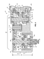
- FIG. 7 is a cross-sectional view taken along line 7 - 7 of FIG. 6 .
- FIGS. 1 and 2 illustrate an angle impact tool 10 that includes a handle or motor assembly 12 and a work attachment 14 .
- the illustrated motor assembly 12 includes a motor 16 , a motor housing 18 , a motor bracket 20 , a first grip portion 22 , a second grip portion 24 , a trigger lever 26 , and a lock ring 28 .
- the lock ring 28 and a plurality of fasteners 30 retains the first and second grip portions 22 and 24 together.
- the motor housing 18 is coupled to the first and second grip portions 22 and 24 by a plurality of fasteners 32 and a U-shaped part 34 .
- a switch 36 is included in the motor assembly 12 between the first and second grip portions 22 and 24 .
- the switch 36 is coupled (mechanically and/or electrically) to the trigger lever 26 , such that actuation of the trigger lever 26 causes actuation of the switch 36 , and therefore, operation of the motor 16 .
- the motor bracket 20 is coupled to the motor 16 by a plurality of fasteners 38 .
- the motor 16 includes an output shaft, such as the illustrated rotor 40 , that is rotatable about a longitudinal handle axis 42 .
- the illustrated motor 16 is an electric motor, but any suitable prime mover, such as the pneumatic motor disclosed in U.S. Published Application No. 2009/0272554, which is herein incorporated by reference, can be utilized.
- a battery and a directional reverse switch are provided on the angle impact tool 10 .
- the illustrated work attachment 14 includes an angle housing 46 and an angle housing plate 48 .
- a plurality of fasteners 50 couple the angle housing plate 48 to the angle housing 46 .
- the motor housing 18 is coupled to the angle housing 46 with a plurality of fasteners 52 .
- the motor bracket 20 is coupled to the angle housing 46 by a plurality of fasteners 54 .
- the illustrated work attachment 14 houses a gear assembly 58 and an impact mechanism 60 .
- the gear assembly 58 includes a first bevel gear 62 coupled to the rotor 40 for rotation with the rotor 40 about the longitudinal handle axis 42 .
- a first bearing 64 is positioned between the first bevel gear 62 and the motor bracket 20 .
- the illustrated gear assembly 58 includes a second bevel gear 66 that meshingly engages the first bevel gear 62 .
- the second bevel gear 66 is coupled to a shaft 68 for rotation with the shaft 68 .
- the shaft 68 is supported in the work attachment 14 by bearings 70 a and 70 b .
- the shaft 68 includes a splined portion 72 near bearing 70 b .
- the shaft 68 rotates about an axis 74 ( FIG. 4 ).
- the splined portion 72 functions as a spur gear and in some embodiments, can be replaced with a spur gear.
- the splined portion 72 engages a gear, such as a first spur gear 76 , such that rotation of the splined portion 72 causes rotation of the first spur gear 76 about an axis 78 ( FIG. 4 ).
- the first spur gear 76 is coupled to a second shaft 80 for rotation with the second shaft 80 ( FIG. 4 ) about the axis 78 .
- the second shaft 80 is supported for rotation with respect to the work attachment 14 by bearings 82 a , 82 b.
- the first spur gear 76 meshes with a second spur gear 84 to cause rotation of the second spur gear 84 about an axis 86 ( FIG. 4 ).
- the second spur gear 84 is coupled to a square drive 88 through the impact mechanism 60 for selectively rotating the square drive 88 .
- the second spur gear 84 and the square drive 88 are supported for rotation within the angle housing 46 by bearings 90 a , 90 b , 90 c ( FIG. 4 ).
- the axes 74 , 78 and 86 are all substantially parallel to each other and are thus each substantially perpendicular to axis 42 .
- the square drive 88 is connectable to a socket or other fastener-driving output element.
- the work attachment 14 can be substantially any tool adapted to be driven by a rotating output shaft of the motor 16 , including but not limited to an impact wrench, gear reducer, and the like.
- the impact mechanism 60 can be a standard impact mechanism, such as a Potts mechanism or a Maurer mechanism.
- the illustrated impact mechanism 60 includes a cam shaft 94 coupled to the second spur gear 84 for rotation with the second spur gear 84 about the second axis 86 .
- the illustrated cam shaft 94 includes opposite cam grooves 96 a , 96 b that define pathways for respective balls 98 a , 98 b .
- the illustrated impact mechanism 60 further includes a hammer 100 that includes opposite cam grooves 102 a , 102 b that are substantially mirror-images of cam grooves 96 a , 96 b .
- the balls 98 a , 98 b are retained between the respective cam grooves 96 a , 96 b , 102 a , 102 b .
- the hammer 100 also includes first and second opposite jaws 104 a , 104 b.
- the first bevel gear 62 actuates the gear assembly 58 and the impact mechanism 60 to functionally drive an output, such as the square drive 88 , as shown in the illustrated embodiment.
- the square drive 88 is rotated about the axis 86 which is non-parallel to the axis 42 .
- the axis 86 is perpendicular to the axis 42 .
- the axis 86 is at an acute or obtuse non-parallel angle to the axis 42 .
- a biasing member such as an axial compression spring 106 is positioned between the second spur gear 84 and the hammer 100 to bias the hammer 100 away from the second spur gear 84 .
- the spring 106 rotates with the second spur gear 84 and the bearing 90 c permits the hammer 100 to rotate with respect to the spring 106 .
- Other configurations are possible, and the illustrated configuration is given by way of example only.
- the illustrated square drive 88 is formed as a single unitary, monolithic piece with first and second jaws 108 a , 108 b to create an anvil 110 .
- the anvil 110 is supported for rotation within the angle housing 46 by the bearing 90 a .
- the jaws 104 a , 104 b impact respective jaws 108 a , 108 b to functionally drive the square drive 88 in response to rotation of the second spur gear 84 .
- the term “functionally drive” is herein defined as a relationship in which the jaws 104 a , 104 b rotate to impact the respective jaws 108 a , 108 b and thereby cause intermittent rotation of the square drive 88 , in response to the impact of jaws 104 a , 104 b on the respective jaws 108 a , 108 b .
- the jaws 104 a , 104 b intermittently impact the jaws 108 a , 108 b , and therefore the jaws 104 a , 104 b functionally drive rotation of the square drive 88 .
- any element that directly or indirectly drives rotation of the hammer to impact the anvil may be said to “functionally drive” any element that is rotated by the anvil as a result of such impact.
- FIGS. 5A-5J The impact cycle is repeated twice every rotation and is illustrated in FIGS. 5A-5J in which the jaws 104 a , 104 b impact the jaws 108 a , 108 b .
- the spring 106 permits the hammer 100 to rebound after impact and balls 98 a , 98 b guide the hammer 100 to ride up around the cam shaft 94 , such that jaws 104 a , 104 b are spaced axially from jaws 108 a , 108 b .
- the jaws 104 a , 104 b are permitted to rotate past the jaws 108 a , 108 b after the rebound.
- FIGS. 5A-5J illustrate an impact cycle of the impact tool of FIGS. 1-4 . Two such impact cycles occur per rotation of the hammer 100 .
- a head height dimension 114 of the work attachment 14 is illustrated in FIG. 4 .
- the head height dimension 114 is the axial distance from the top of the angle housing plate 48 to the bottom of the angle housing 46 .
- the head height dimension 114 is reduced so that the work attachment 14 can fit into small spaces.
- the motor housing 18 defines a motor housing height dimension 118 , as shown in FIG. 4 .
- the head height dimension 114 is smaller than or substantially equal to the motor housing height dimension 118 .
- the head height dimension 114 is less than two inches, and the angle impact tool 10 has a maximum torque of about 180 foot-pounds and a rate of rotation of about 7,100 rotations-per-minute.
- FIGS. 6 and 7 illustrate an alternate embodiment of an angle head work attachment 214 for an angle impact tool.
- the angle head work attachment 214 is coupled to a handle and motor 216 having a rotor 240 .
- the motor 216 is supported by a motor housing 218 .
- the illustrated motor 216 is an electric motor, but any suitable prime mover, such as the pneumatic motor disclosed in U.S. Published Application No. 2009/0272554, which is herein incorporated by reference, can be utilized.
- a battery and a directional reverse switch are provided on the angle impact tool.
- the angle head work attachment 214 includes an angle housing 246 and an angle housing plate 248 that support a gear assembly 258 and an impact mechanism 260 .
- the rotor 240 rotates about a longitudinal handle axis 242 .
- a first bevel gear 262 is coupled to the rotor 240 for rotation with the rotor 240 about the longitudinal handle axis 242 .
- a first bearing 264 is positioned between the first bevel gear 262 and the motor housing 218 .
- the illustrated gear assembly 258 includes a second bevel gear 266 that meshingly engages the first bevel gear 262 .
- the second bevel gear 266 is coupled to a shaft 268 for rotation with the shaft 268 .
- the shaft 268 is supported in the work attachment 214 by bearings 270 a and 270 b .
- the shaft 268 includes a splined portion 272 near bearing 270 b .
- the shaft 268 rotates about an axis 274 .
- the splined portion 272 functions as a spur gear and in some embodiments, can be replaced with a spur gear.
- the splined portion 272 engages a gear, such as a first spur gear 276 , such that rotation of the splined portion 272 causes rotation of the first spur gear 276 about an axis 278 .
- the first spur gear 276 is coupled to a second shaft 280 for rotation with the second shaft 280 about the axis 278 .
- the second shaft 280 is supported for rotation with respect to the work attachment 214 by bearings 282 b.
- the first spur gear 276 meshes with a second spur gear 284 to cause rotation of the second spur gear 284 about an axis 286 .
- the second spur gear 284 is coupled to a square drive 288 through the impact mechanism 260 for selectively rotating the square drive 288 .
- the second spur gear 284 and the square drive 288 are supported for rotation with respect to the work attachment 214 by bushing 290 a and bearings 290 b , 290 c .
- the axes 274 , 278 and 286 are all substantially parallel to each other and are thus each substantially perpendicular to axis 242 .
- the square drive 288 is connectable to a socket or other fastener-driving output element.
- the work attachment 214 can be substantially any tool adapted to be driven by a rotating output shaft of the motor 216 , including but not limited to an impact wrench, gear reducer, and the like.
- the impact mechanism 260 can be a standard impact mechanism, such as a Potts mechanism or a Maurer mechanism.
- the illustrated impact mechanism 260 includes a cam shaft 294 coupled to the second spur gear 284 for rotation with the second spur gear 284 about the second axis 286 .
- the illustrated cam shaft 294 includes opposite cam grooves 296 a , 296 b that define pathways for respective balls 298 a , 298 b .
- the illustrated impact mechanism 260 further includes a hammer 300 that includes opposite cam grooves 302 a , 302 b that are substantially mirror-images of cam grooves 296 a , 296 b .
- the balls 298 a , 298 b are retained between the respective cam grooves 296 a , 296 b , 302 a , 302 b .
- the hammer 300 also includes first and second opposite jaws 304 a , 304 b.
- the first bevel gear 262 actuates the gear assembly 258 and the impact mechanism 260 to functionally drive an output, such as the square drive 288 , as shown in the illustrated embodiment.
- the square drive 288 is rotated about the axis 286 which is non-parallel to the axis 242 .
- the axis 286 is perpendicular to the axis 242 .
- the axis 286 is at an acute or obtuse non-parallel angle to the axis 242 .
- a biasing member such as an axial compression spring 306 is positioned between the second spur gear 284 and the hammer 300 to bias the hammer 300 away from the second spur gear 284 .
- the spring 306 rotates with the hammer 100 and the bearing 290 c permits the second spur gear 284 to rotate with respect to the spring 106 .
- Other configurations are possible, and the illustrated configuration is given by way of example only.
- the illustrated square drive 288 is formed as a single unitary, monolithic piece with first and second jaws 308 a , 308 b to create an anvil 310 .
- the anvil 310 is supported for rotation within the work attachment 214 by the bushing 290 a .
- the jaws 304 a , 304 b impact respective jaws 308 a , 308 b to functionally drive the square drive 288 in response to rotation of the second spur gear 284 .
- the impact cycle is repeated twice every rotation and is similar to the impact cycled illustrated in FIGS. 5A-5J .
- the jaws 304 a , 304 b impact the jaws 308 a , 308 b .
- the spring 306 permits the hammer 300 to rebound after impact and balls 298 a , 298 b guide the hammer 300 to ride up around the cam shaft 294 , such that jaws 304 a , 304 b are spaced axially from jaws 308 a , 308 b .
- the jaws 304 a , 304 b are permitted to rotate past the jaws 308 a , 308 b after the rebound.
- a head height dimension 314 of the work attachment 214 is illustrated in FIG. 7 .
- the head height dimension 314 is the axial distance from the top of the angle housing 246 to the bottom of the angle housing 246 .
- the head height dimension 314 is reduced so that the work attachment 214 can fit into small spaces.
- the motor housing 218 defines a motor housing height dimension 318 , as shown in FIG. 7 .
- the head height dimension 314 is smaller than or substantially equal to the motor housing height dimension 318 .
Abstract
Description
Claims (7)
Priority Applications (9)
| Application Number | Priority Date | Filing Date | Title |
|---|---|---|---|
| US13/033,241 US8925646B2 (en) | 2011-02-23 | 2011-02-23 | Right angle impact tool |
| CN201280010271.4A CN103608149B (en) | 2011-02-23 | 2012-02-21 | Right angle impact tool |
| PCT/US2012/025850 WO2012115921A2 (en) | 2011-02-23 | 2012-02-21 | Right angle impact tool |
| CN201610580589.6A CN106181842B (en) | 2011-02-23 | 2012-02-21 | Right angle impact tool |
| EP12749794.9A EP2678138B1 (en) | 2011-02-23 | 2012-02-21 | Right angle impact tool |
| EP17152448.1A EP3178615B1 (en) | 2011-02-23 | 2012-02-21 | Right angle impact tool |
| US14/251,552 US9592600B2 (en) | 2011-02-23 | 2014-04-11 | Angle impact tools |
| US14/251,567 US9550284B2 (en) | 2011-02-23 | 2014-04-12 | Angle impact tool |
| US14/552,536 US10131037B2 (en) | 2011-02-23 | 2014-11-25 | Angle impact tool |
Applications Claiming Priority (1)
| Application Number | Priority Date | Filing Date | Title |
|---|---|---|---|
| US13/033,241 US8925646B2 (en) | 2011-02-23 | 2011-02-23 | Right angle impact tool |
Related Child Applications (2)
| Application Number | Title | Priority Date | Filing Date |
|---|---|---|---|
| US14/251,552 Continuation-In-Part US9592600B2 (en) | 2011-02-23 | 2014-04-11 | Angle impact tools |
| US14/251,567 Continuation US9550284B2 (en) | 2011-02-23 | 2014-04-12 | Angle impact tool |
Publications (2)
| Publication Number | Publication Date |
|---|---|
| US20120211249A1 US20120211249A1 (en) | 2012-08-23 |
| US8925646B2 true US8925646B2 (en) | 2015-01-06 |
Family
ID=46651813
Family Applications (3)
| Application Number | Title | Priority Date | Filing Date |
|---|---|---|---|
| US13/033,241 Active 2033-02-26 US8925646B2 (en) | 2011-02-23 | 2011-02-23 | Right angle impact tool |
| US14/251,567 Active 2032-01-13 US9550284B2 (en) | 2011-02-23 | 2014-04-12 | Angle impact tool |
| US14/552,536 Active 2032-03-29 US10131037B2 (en) | 2011-02-23 | 2014-11-25 | Angle impact tool |
Family Applications After (2)
| Application Number | Title | Priority Date | Filing Date |
|---|---|---|---|
| US14/251,567 Active 2032-01-13 US9550284B2 (en) | 2011-02-23 | 2014-04-12 | Angle impact tool |
| US14/552,536 Active 2032-03-29 US10131037B2 (en) | 2011-02-23 | 2014-11-25 | Angle impact tool |
Country Status (4)
| Country | Link |
|---|---|
| US (3) | US8925646B2 (en) |
| EP (2) | EP2678138B1 (en) |
| CN (2) | CN106181842B (en) |
| WO (1) | WO2012115921A2 (en) |
Cited By (19)
| Publication number | Priority date | Publication date | Assignee | Title |
|---|---|---|---|---|
| US20130180746A1 (en) * | 2012-01-17 | 2013-07-18 | Basso Industry Corp. | Pneumatic impact tool with a spindle positioning device |
| US20140262396A1 (en) * | 2013-03-12 | 2014-09-18 | Ingersoll-Rand Company | Angle Impact Tool |
| US20140368133A1 (en) * | 2012-02-15 | 2014-12-18 | Hitachi Koki Co., Ltd. | Electric working machine |
| US9022888B2 (en) | 2013-03-12 | 2015-05-05 | Ingersoll-Rand Company | Angle impact tool |
| USD767357S1 (en) * | 2014-07-09 | 2016-09-27 | C. & E. Fein Gmbh | Grinding machine |
| US9550284B2 (en) | 2011-02-23 | 2017-01-24 | Ingersoll-Rand Company | Angle impact tool |
| US9592600B2 (en) | 2011-02-23 | 2017-03-14 | Ingersoll-Rand Company | Angle impact tools |
| US20180085900A1 (en) * | 2013-03-15 | 2018-03-29 | Ingersoll-Rand Company | Low-Profile Impact Tools |
| TWI626132B (en) * | 2017-06-13 | 2018-06-11 | De Poan Pneumatic Corp | Pneumatic hand tool with rotary knocking kinetic energy |
| EP3434420A1 (en) | 2017-07-24 | 2019-01-30 | Ingersoll-Rand Company | Outrunner motor in cordless power tool |
| EP3437801A1 (en) | 2017-07-31 | 2019-02-06 | Ingersoll-Rand Company | Impact tool angular velocity measurement system |
| US11318589B2 (en) | 2018-02-19 | 2022-05-03 | Milwaukee Electric Tool Corporation | Impact tool |
| US11484997B2 (en) * | 2018-12-21 | 2022-11-01 | Milwaukee Electric Tool Corporation | High torque impact tool |
| US11511400B2 (en) * | 2018-12-10 | 2022-11-29 | Milwaukee Electric Tool Corporation | High torque impact tool |
| USD971706S1 (en) | 2020-03-17 | 2022-12-06 | Milwaukee Electric Tool Corporation | Rotary impact wrench |
| US20230139577A1 (en) * | 2021-11-03 | 2023-05-04 | Robert Bosch Gmbh | Hand-Held Power Tool with a Motor Support for a Drive Motor |
| US11701759B2 (en) * | 2019-09-27 | 2023-07-18 | Makita Corporation | Electric power tool |
| US11806855B2 (en) | 2019-09-27 | 2023-11-07 | Makita Corporation | Electric power tool, and method for controlling motor of electric power tool |
| TWI821631B (en) * | 2020-01-20 | 2023-11-11 | 鑽全實業股份有限公司 | Hand-held power tool |
Families Citing this family (12)
| Publication number | Priority date | Publication date | Assignee | Title |
|---|---|---|---|---|
| US20140262394A1 (en) * | 2013-03-14 | 2014-09-18 | Milwaukee Electric Tool Corporation | Impact tool |
| US10926383B2 (en) * | 2013-03-14 | 2021-02-23 | Milwaukee Electric Tool Corporation | Impact tool |
| US9592591B2 (en) * | 2013-12-06 | 2017-03-14 | Ingersoll-Rand Company | Impact tools with speed controllers |
| CN106030128B (en) * | 2013-12-17 | 2019-11-26 | 凯特克分部尤尼克斯公司 | Reaction washer and its tightening casing |
| EP2933061A3 (en) * | 2014-04-11 | 2015-12-09 | Ingersoll-Rand Company | Angle impact tools |
| DE102014109412B3 (en) * | 2014-07-04 | 2015-09-10 | C. & E. Fein Gmbh | Friction bearing between runner and anvil in an impact wrench |
| JP7083808B2 (en) * | 2017-03-07 | 2022-06-13 | 株式会社マキタ | Tool holding device, power tool, impact driver |
| CN108687708B (en) * | 2017-04-07 | 2021-05-07 | 车王电子股份有限公司 | Impact tool |
| US11110572B2 (en) * | 2019-04-24 | 2021-09-07 | Hsieh Yuan Liao | Connecting shaft structure of electric screwdriver |
| TWI703017B (en) | 2019-08-14 | 2020-09-01 | 車王電子股份有限公司 | Impact wrench |
| JP7373376B2 (en) * | 2019-12-02 | 2023-11-02 | 株式会社マキタ | impact tools |
| JP2022057465A (en) * | 2020-09-30 | 2022-04-11 | パナソニック株式会社 | Attachment for impact rotary tool and tool system |
Citations (188)
| Publication number | Priority date | Publication date | Assignee | Title |
|---|---|---|---|---|
| US2267781A (en) | 1939-11-09 | 1941-12-30 | Albertson & Co Inc | Electric sanding machine |
| US2585486A (en) * | 1949-03-17 | 1952-02-12 | Independent Pneumatic Tool Co | Impact type clutch |
| US3181672A (en) | 1961-06-20 | 1965-05-04 | Gardner Denver Co | Tension control wrench |
| US3223182A (en) | 1962-08-07 | 1965-12-14 | Nitto Kohki Co | Powered impact tools |
| US3270593A (en) | 1963-10-28 | 1966-09-06 | Skil Corp | Power operated hand tool of the rotary impact type |
| US3352368A (en) | 1965-08-30 | 1967-11-14 | Black & Decker Mfg Co | Pivoted trigger means for power-operated reversible tool |
| US3380539A (en) | 1964-09-08 | 1968-04-30 | Skil Corp | Impact clutch |
| US3465646A (en) | 1967-10-05 | 1969-09-09 | Aro Corp | Pneumatic motor structure |
| US3661217A (en) | 1970-07-07 | 1972-05-09 | Spencer B Maurer | Rotary impact tool and clutch therefor |
| US3848680A (en) | 1973-12-26 | 1974-11-19 | Skil Corp | Impact clutch mechanism |
| US3949944A (en) | 1971-10-13 | 1976-04-13 | H. F. Wilson Engineering Company | Air powered rotary wire cutting and wrapping tool |
| US3951217A (en) | 1974-09-03 | 1976-04-20 | Chicago Pneumatic Tool Company | Impact air wrench having a two position pressure regulator |
| US4173828A (en) | 1977-12-19 | 1979-11-13 | Leopold Paul Lustig | Interchangeable tool operating apparatus with plural motion |
| US4222443A (en) | 1978-07-21 | 1980-09-16 | Hilti Aktiengesellschaft | Motor-driven hammer drill |
| USD256980S (en) | 1977-12-22 | 1980-09-23 | Snap-On Tools Corporation | Impact wrench |
| US4235850A (en) | 1978-08-07 | 1980-11-25 | Mobil Oil Corporation | Process for the recovery of uranium from a saline lixiviant |
| US4287795A (en) | 1979-11-09 | 1981-09-08 | The Rotor Tool Company | Adjustable blade wrench |
| US4355564A (en) | 1979-03-30 | 1982-10-26 | Atlas Copco Aktiebolag | Pneumatic reciprocating mechanism |
| US4379492A (en) | 1979-06-04 | 1983-04-12 | Nippon Pneumatic Manufacturing Co., Ltd. | Torque control apparatus for pneumatic impact wrench |
| US4403679A (en) | 1981-04-01 | 1983-09-13 | Cooper Industries, Inc. | Angle drive lubricator |
| US4434858A (en) | 1982-01-18 | 1984-03-06 | The Stanley Works | Air tool with stall torque regulator and air biasing mechanism |
| US4488604A (en) | 1982-07-12 | 1984-12-18 | The Stanley Works | Torque control clutch for a power tool |
| US4585078A (en) | 1982-09-09 | 1986-04-29 | Alexandrov Vladimir M | Rotary impact tool |
| US4625999A (en) | 1981-11-19 | 1986-12-02 | Stanley Aviation Corporation | Remotely-operable ball joint connector |
| US4708210A (en) | 1984-03-20 | 1987-11-24 | Atlas Copco Aktiebolag | Pneumatic rotary tool |
| US4719976A (en) | 1985-02-26 | 1988-01-19 | Robert Bosch Gmbh | Hammer drill |
| US4732218A (en) | 1985-05-08 | 1988-03-22 | Hilti Aktiengesellschaft | Hammer drill with separate and interconnectable drive means |
| US4735020A (en) | 1986-03-06 | 1988-04-05 | Metabowerke Gmbh & Co. | Portable electric grinder |
| US4740144A (en) | 1987-05-04 | 1988-04-26 | Dresser Industries, Inc. | Reversible radial vane air motor |
| US4776561A (en) | 1986-12-05 | 1988-10-11 | The Stanley Works | Trigger control for air tool handle |
| US4779382A (en) | 1986-07-12 | 1988-10-25 | C. & E. Fein Gmbh & Co. | Mechanism for mounting a disk-shaped attachment on the spindle of a portable electric tool |
| US4798249A (en) | 1986-10-03 | 1989-01-17 | Hilti Aktiengesellschaft | Lockable striking mechanism for hammer drill |
| US4799833A (en) * | 1987-12-14 | 1989-01-24 | Dresser Industries, Inc. | Clutch for positive feed drill |
| US4867250A (en) | 1986-08-18 | 1989-09-19 | Ritt Corporation | Pneumatic impact imparting tool |
| US4974475A (en) | 1989-07-19 | 1990-12-04 | Skil Corporation | Cordless powered ratchet wrench |
| US5022469A (en) | 1989-01-16 | 1991-06-11 | Atlas Copco Tools Aktiebolag | Exhaust means for pneumatic power tool |
| USD323961S (en) | 1989-02-07 | 1992-02-18 | Makita Electric Works, Ltd. | Portable electric drill |
| US5143161A (en) * | 1991-09-20 | 1992-09-01 | P.V. Tool, Inc. | Right angle positive feed tapper |
| US5210918A (en) | 1991-10-29 | 1993-05-18 | Wozniak Walter E | Pneumatic slide hammer |
| USD335808S (en) | 1991-09-20 | 1993-05-25 | Ingersoll-Rand Company | Electric motor driven nutrunner |
| USD339726S (en) | 1992-04-03 | 1993-09-28 | Ingersoll-Rand Company | Impact wrench |
| US5293747A (en) | 1992-07-27 | 1994-03-15 | Ingersoll-Rand Company | Power regulator for a pressure fluid motor |
| US5346021A (en) | 1993-05-10 | 1994-09-13 | The Stanley Works | Fastening tool having improved pressure regulator device |
| US5346024A (en) | 1992-06-22 | 1994-09-13 | Ingersoll-Rand Company | Tool construction |
| USD352645S (en) | 1993-06-01 | 1994-11-22 | Makita Corporation | Electric ratchet wrench |
| US5443196A (en) | 1991-12-11 | 1995-08-22 | Illinois Tool Works, Inc. | Fastener applicator |
| US5471898A (en) | 1993-12-20 | 1995-12-05 | Forman; Edward P. | Breaker bar with 90 degree rotating socket connector head |
| US5505676A (en) | 1994-01-25 | 1996-04-09 | The Stanley Works | Clutch torque control |
| USD372850S (en) | 1995-01-09 | 1996-08-20 | Ingersoll-Rand Company | Electric motor driven angle head nutrunner |
| JPH0911140A (en) * | 1995-06-27 | 1997-01-14 | Matsushita Electric Works Ltd | Rotary tool |
| US5626198A (en) | 1995-04-26 | 1997-05-06 | Atlas Copco Tools | Pneumatic torque impulse tool |
| USD380949S (en) | 1995-10-24 | 1997-07-15 | K.K.U. Limited | Ratchet wrench |
| USD388678S (en) | 1996-12-18 | 1998-01-06 | Ingersoll-Rand Company | Impact wrench |
| USD393580S (en) | 1996-12-18 | 1998-04-21 | Ingersoll-Rand Company | Impact wrench |
| US5813477A (en) | 1996-05-23 | 1998-09-29 | Chicago Pneumatic Tool Company | Vibration-reduced impact tool and vibration isolator therefor |
| USD400771S (en) | 1997-06-09 | 1998-11-10 | Porter-Cable Corporation | Plate joiner |
| USD403564S (en) | 1997-06-24 | 1999-01-05 | S.P. Air Kabusiki Kaisha | Impact wrench |
| US5906244A (en) | 1997-10-02 | 1999-05-25 | Ingersoll-Rand Company | Rotary impact tool with involute profile hammer |
| USD414093S (en) | 1998-05-22 | 1999-09-21 | Black & Decker | Right angle drill |
| WO1999049553A1 (en) | 1998-03-26 | 1999-09-30 | Gouge Lloyd V Jr | Cordless, high torque power tool |
| US6039231A (en) | 1994-05-18 | 2000-03-21 | Stanley Fastening Systems, L.P. | Adjustable energy control valve for a fastener driving device |
| US6044917A (en) | 1996-03-18 | 2000-04-04 | Brunhoelzl; George | Pneumatic tool with side exhaust |
| US6047779A (en) | 1997-07-29 | 2000-04-11 | Chicago Pneumatic Tool Company | Twin lobe impact mechanism |
| US6053080A (en) | 1997-10-29 | 2000-04-25 | Maeda Metal Industries, Ltd. | Device for tightening bolt and/or nut |
| US6082468A (en) | 1998-04-20 | 2000-07-04 | Snap-On Tools Company | Interchangeable grips for power hand tools |
| US6109366A (en) | 1997-02-19 | 2000-08-29 | Atlas Copco Tools Ab | Power tool with lubricated angle drive |
| USD434297S (en) | 1999-05-28 | 2000-11-28 | Ingersoll-Rand Company | Impact wrench |
| US6158459A (en) | 2000-04-04 | 2000-12-12 | Chang; An-Mei | Oil nozzle structure for pneumatic tools |
| USD434958S (en) | 2000-01-26 | 2000-12-12 | S.P. Air Kabasiki Kaisha | Impact wrench |
| US6179063B1 (en) | 1999-05-03 | 2001-01-30 | The Stanley Works | Impulse wrench |
| USD436818S1 (en) | 2000-01-26 | 2001-01-30 | S.P. Air Kabusiki Kaisha | Impact wrench |
| USD437760S1 (en) | 1999-10-05 | 2001-02-20 | S.P. Air Kabusiki Kaisha | Impact wrench |
| USD441628S1 (en) | 2000-08-18 | 2001-05-08 | Campbell Hausfeld/Scott Fetzer Company | Impact wrench |
| US6250399B1 (en) | 1999-09-13 | 2001-06-26 | Chicago Pneumatic Tool Company | Pneumatic tool with a reverse valve having an overdrive |
| USD444363S1 (en) | 2000-08-01 | 2001-07-03 | Makita Corporation | Portable electric drill |
| JP2001198853A (en) | 2000-01-19 | 2001-07-24 | Makita Corp | Rotary striking tool |
| USD447029S1 (en) | 2000-12-18 | 2001-08-28 | Yung Yung Sun | Pneumatic tool |
| US6338389B1 (en) | 2001-03-08 | 2002-01-15 | An-Mei Chang | Air outlet regulating mechanism for pneumatic tool |
| JP3248296B2 (en) | 1993-04-02 | 2002-01-21 | 日立工機株式会社 | Impact tool |
| USD454475S1 (en) | 2000-12-14 | 2002-03-19 | Koji Taga | End cap for portable double-knock-type air impact wrench |
| US20020035890A1 (en) | 2000-09-26 | 2002-03-28 | Tenryu Seikyo Kabushiki Kaisha | Metal bonded drilling and/or chamfering tool |
| USD458824S1 (en) | 2001-06-27 | 2002-06-18 | Ting-Yuan Chen | Pneumatic tool |
| USD461110S1 (en) | 2001-06-11 | 2002-08-06 | Kabushiki Kaisha Shinano Seisakusho | Portable air impact wrench |
| US6460629B2 (en) | 2000-11-15 | 2002-10-08 | The Stanley Works | Pneumatic tool and system for applying torque to fasteners |
| US6461088B2 (en) | 1998-04-23 | 2002-10-08 | Black & Decker Inc. | Two speed right angle drill |
| USD465982S1 (en) | 2001-07-06 | 2002-11-26 | Taga Corporation | Pneumatic tool with push button reverse |
| US6491111B1 (en) | 2000-07-17 | 2002-12-10 | Ingersoll-Rand Company | Rotary impact tool having a twin hammer mechanism |
| US6502485B1 (en) | 2002-02-25 | 2003-01-07 | Joe Martin Salazar | Impact ratchet wrench |
| US6505690B2 (en) | 2000-03-30 | 2003-01-14 | Makita Corporation | Hydraulic unit and electric power tool to which the hydraulic unit is incorporated |
| USD469673S1 (en) | 2001-11-30 | 2003-02-04 | Ingersoll-Rand Company | Impact wrench |
| JP3372398B2 (en) | 1995-06-27 | 2003-02-04 | 松下電工株式会社 | Rotary tool |
| USD472782S1 (en) | 2002-04-02 | 2003-04-08 | Snap-On Technologies, Inc. | Impact wrench |
| US20030075348A1 (en) | 2001-10-24 | 2003-04-24 | Ingersoll-Rand Company | Rocker button activated forward/reverse mechanism for a power tool |
| US6561284B2 (en) | 2000-12-28 | 2003-05-13 | Koji Taga | Reverse apparatus for air impact wrench |
| USD476210S1 (en) | 2002-09-17 | 2003-06-24 | Tranmax Machinery Co., Ltd | Pneumatic tool |
| USD476870S1 (en) | 2002-07-11 | 2003-07-08 | Makita Corporation | Portable electric drill |
| USD477512S1 (en) | 2002-11-18 | 2003-07-22 | Basso Industry Corp. | Pneumatic tool |
| US20040014411A1 (en) | 2000-12-30 | 2004-01-22 | Stephan Jonas | Manual machine tool |
| US6691798B1 (en) | 2002-06-19 | 2004-02-17 | Steven James Lindsay | Variable hand pressure activated power tool |
| US6708779B2 (en) | 2000-12-28 | 2004-03-23 | Koji Taga | Reverse apparatus for air impact wrench |
| US6719067B2 (en) | 2001-12-27 | 2004-04-13 | Taga Corporation | Insert for a plastic power tool housing |
| CN1494988A (en) | 2002-09-13 | 2004-05-12 | 株式会社信浓制作所 | Pneumatic socket wrench |
| US6782956B1 (en) | 2003-03-07 | 2004-08-31 | Ingersoll-Rand Company | Drive system having an inertial valve |
| US6789447B1 (en) | 1998-11-23 | 2004-09-14 | Frederick L. Zinck | Reversible ratchet head assembly |
| US20040177980A1 (en) | 2003-03-13 | 2004-09-16 | Ingersoll-Rand Company | Pneumatic tool muffler |
| USD496243S1 (en) | 2003-12-23 | 2004-09-21 | Yung-Chao Huang | Pneumatic impact wrench |
| US6796385B1 (en) | 2003-03-13 | 2004-09-28 | Alcoa Global Fasteners, Inc. | Fastener driving machine and associated method |
| USD497529S1 (en) | 2004-02-02 | 2004-10-26 | Ingersoll-Rand Company | Impact wrench |
| USD497785S1 (en) | 2003-06-09 | 2004-11-02 | Kabushiki Kaisha Shinano Seisakusho | Ratchet wrench |
| USD497787S1 (en) | 2004-03-09 | 2004-11-02 | Chi-Shen Liao | Air impact wrench |
| USD502071S1 (en) | 2003-08-18 | 2005-02-22 | Black & Decker Inc. | Screwdriver |
| US6863135B2 (en) | 2000-08-04 | 2005-03-08 | Hitachi Koki Co., Ltd. | Electric power tool |
| US6863134B2 (en) | 2003-03-07 | 2005-03-08 | Ingersoll-Rand Company | Rotary tool |
| US6880645B2 (en) | 2002-06-14 | 2005-04-19 | S.P. Air Kabusiki Kaisha | Pneumatic rotary tool |
| US6883619B1 (en) | 2004-01-22 | 2005-04-26 | Yung-Chao Huang | Bidirectional pneumatic impact wrench |
| US6889778B2 (en) | 2003-01-31 | 2005-05-10 | Ingersoll-Rand Company | Rotary tool |
| US20050161243A1 (en) | 2004-01-23 | 2005-07-28 | Ingersoll-Rand Company | Titanium based containment structures for handheld impact tools |
| US6929074B1 (en) | 2004-06-08 | 2005-08-16 | Mobiletron Electronics Co., Ltd. | Elbow-type power hand tool |
| US6935437B2 (en) | 2002-09-12 | 2005-08-30 | Kabushiki Kaisha Shinano Seisakusho | Air drill |
| USD510513S1 (en) | 2003-05-28 | 2005-10-11 | Robert Bosch Gmbh | Electrically operated offset screwdriver |
| US6957706B2 (en) | 2003-06-12 | 2005-10-25 | Hilti Aktiengesellschaft | Attachment member |
| USD511284S1 (en) | 2003-10-20 | 2005-11-08 | S. & E. Fein Gmbh | Oscillatory drive |
| US6968908B2 (en) | 2003-02-05 | 2005-11-29 | Makita Corporation | Power tools |
| US20050279196A1 (en) | 2004-06-21 | 2005-12-22 | Hollar Kenneth G | Angular impact wrench |
| US20050279519A1 (en) | 2004-06-17 | 2005-12-22 | One World Technologies Limited | Right angle impact driver |
| US7036605B2 (en) | 2000-03-16 | 2006-05-02 | Makita Corporation | Power tools |
| USD519807S1 (en) | 2005-07-06 | 2006-05-02 | Sunmatch Industrial Co., Ltd. | Pneumatic tool |
| US7036795B2 (en) | 2003-11-17 | 2006-05-02 | Kabushiki Kaisha Shinano Seisakusho | Valve apparatus for air tool |
| US20060090914A1 (en) | 2004-10-28 | 2006-05-04 | Basso Industry Corp. | Air inlet structure for a pneumatic tool |
| US7040414B1 (en) | 2004-11-16 | 2006-05-09 | David Kuo | Pneumatic tool |
| USD521339S1 (en) | 2005-08-26 | 2006-05-23 | Sunmatch Industrial Co., Ltd. | Pneumatic tool |
| US20060107798A1 (en) | 2004-11-24 | 2006-05-25 | Falzone Loren P | Ratchet-based, torqued-enhanced fastener tool |
| USD525502S1 (en) | 2005-08-31 | 2006-07-25 | Sunmatch Industrial Co., Ltd. | Pneumatic tool |
| US7080578B2 (en) | 2004-09-10 | 2006-07-25 | Sp Air Kabusiki Kaisha Corporation | Hand tool with impact drive and speed reducing mechanism |
| US7089833B2 (en) | 2003-12-18 | 2006-08-15 | H.B. Products, Inc. | Air actuated pneumatic impact wrench lug bolt tool |
| US7109675B2 (en) | 2001-05-09 | 2006-09-19 | Makita Corporation | Power tools |
| USD529353S1 (en) | 2004-09-17 | 2006-10-03 | Eastway Fair Company Limited | Right angle impact driver |
| USD530171S1 (en) | 2005-03-31 | 2006-10-17 | Chicago Pneumatic Tool Company | Pneumatic ratchet wrench |
| US7137457B2 (en) | 2003-05-30 | 2006-11-21 | Robert Bosch Gmbh | Hand-held machine tool |
| US7140179B2 (en) | 2004-11-10 | 2006-11-28 | Campbell Hausfeld/Scott Fetzer Company | Valve |
| USD534047S1 (en) | 2004-07-07 | 2006-12-26 | Basso Industry Corp. | Pneumatic spanner |
| US20070000674A1 (en) | 2005-02-10 | 2007-01-04 | Stefan Sell | Hammer |
| USD535536S1 (en) | 2006-01-19 | 2007-01-23 | Snap-On Incorporated | Cordless impact tool |
| US7174971B1 (en) | 2005-12-29 | 2007-02-13 | Sunmatch Industrial Co., Ltd. | Clockwise or counterclockwise rotation control device of a pneumatic tool |
| US7191849B2 (en) | 2004-08-19 | 2007-03-20 | Hyphone Machine Industry Co., Ltd. | Pneumatic tool |
| USD540134S1 (en) | 2006-06-22 | 2007-04-10 | Chicago Pneumatic Tool Company | Impact wrench |
| USD540640S1 (en) | 2006-06-22 | 2007-04-17 | Chicago Pneumatic Tool Company | Impact wrench |
| US20070181322A1 (en) | 2003-10-03 | 2007-08-09 | Hansson Gunnar C | Power tool with angle drive and pinion adjustment |
| US20070289760A1 (en) | 2006-06-16 | 2007-12-20 | Exhaust Technologies, Inc. | Shock attenuating coupling device and rotary impact tool |
| US7311155B2 (en) | 2005-12-13 | 2007-12-25 | Mighty Seven International Co., Ltd. | Pneumatic tool with direction switch operable with single hand |
| US20080066937A1 (en) | 2006-09-18 | 2008-03-20 | Sp Air Kabushiki Kaisha | Reversible Valve Assembly for a Pneumatic Tool |
| USD569206S1 (en) | 2007-01-23 | 2008-05-20 | Makita Corporation | Portable electric driver |
| USD572991S1 (en) | 2007-02-02 | 2008-07-15 | Sunmatch Industrial Co., Ltd. | Pneumatic tool |
| USD580248S1 (en) | 2008-05-05 | 2008-11-11 | Ingersoll-Rand Company | Pneumatic tool |
| US20080289843A1 (en) * | 2006-11-10 | 2008-11-27 | Joel Townsan | Electric hand screwdriver with adjustable head |
| US7461704B2 (en) | 2007-03-19 | 2008-12-09 | Sunmatch Industrial Co., Ltd. | Airflow control structure for pneumatic tools |
| US20090038816A1 (en) | 2007-08-09 | 2009-02-12 | Joshua Odell Johnson | Impact wrench |
| US7492125B2 (en) | 2004-11-04 | 2009-02-17 | Milwaukee Electric Tool Corporation | Power tools, battery chargers and batteries |
| USD590226S1 (en) | 2006-05-22 | 2009-04-14 | Fairskq (Taiwan) Co., Ltd | Air impact wrench |
| USD590680S1 (en) | 2006-04-18 | 2009-04-21 | Ingersoll-Rand Company | Air tool |
| USD590681S1 (en) | 2006-04-18 | 2009-04-21 | Ingersoll-Rand Company | Air tool |
| USD591127S1 (en) | 2007-12-21 | 2009-04-28 | Taga Corporation | Impact tool |
| US7537064B2 (en) | 2001-01-23 | 2009-05-26 | Black & Decker Inc. | Multispeed power tool transmission |
| US20090272554A1 (en) | 2008-05-05 | 2009-11-05 | Ingersoll-Rand Company | Motor assembly for pneumatic tool |
| US20090272556A1 (en) | 2008-05-05 | 2009-11-05 | Ingersoll-Rand Company | Angle head and bevel gear for tool |
| USD610888S1 (en) | 2008-09-11 | 2010-03-02 | Kabushiki Kaisha Shinano Seisakusho | Impact wrench |
| US20100107423A1 (en) | 2008-10-30 | 2010-05-06 | Black & Decker Inc | Handle and attachments for right angle drill |
| USD617620S1 (en) | 2009-06-04 | 2010-06-15 | Ingersoll-Rand Company | Power ratchet wrench |
| US7770660B2 (en) | 2007-11-21 | 2010-08-10 | Black & Decker Inc. | Mid-handle drill construction and assembly process |
| US20100276168A1 (en) | 2009-04-30 | 2010-11-04 | Sankarshan Murthy | Power tool with impact mechanism |
| US7828072B2 (en) | 2004-10-26 | 2010-11-09 | Panasonic Electric Works Co., Ltd. | Impact tool |
| US7836797B2 (en) | 2006-11-16 | 2010-11-23 | Robert Bosch Gmbh | Tool ratchet |
| WO2011002855A1 (en) | 2009-06-30 | 2011-01-06 | Ingersoll Rand Company | Ratchet wrench with collar-actuated reversing mechanism |
| EP2277469A2 (en) | 2005-05-17 | 2011-01-26 | IMT Integral Medizintechnik AG | Percussion tool, in particular for surgical use |
| US20110139474A1 (en) | 2008-05-05 | 2011-06-16 | Warren Andrew Seith | Pneumatic impact tool |
| WO2011111850A1 (en) | 2010-03-08 | 2011-09-15 | Hitachi Koki Co., Ltd. | Impact tool |
| US20110233257A1 (en) | 2008-10-15 | 2011-09-29 | Chervon (Hk) Limited | Nailer device |
| US20120118596A1 (en) | 2010-11-16 | 2012-05-17 | Scott John S | Impact tool |
| US20120138329A1 (en) | 2010-12-03 | 2012-06-07 | Storm Pneumatic Tool Co., Ltd. | Structure of pneumatic impact wrench |
| US20120152580A1 (en) | 2010-12-20 | 2012-06-21 | Christopher Mattson | Hand power tool and drive train |
| WO2012115921A2 (en) | 2011-02-23 | 2012-08-30 | Ingersoll Rand Company | Right angle impact tool |
| US8267192B2 (en) | 2009-02-24 | 2012-09-18 | Black & Decker Inc. | Ergonomic handle for power tool |
| US8297373B2 (en) | 2010-02-19 | 2012-10-30 | Milwaukee Electric Tool Corporation | Impact device |
| US8319379B2 (en) | 2008-02-26 | 2012-11-27 | Hitachi Koki Co., Ltd. | Portable electrical power tool |
| US20130025900A1 (en) | 2011-07-27 | 2013-01-31 | Christopher Anthony Kokinelis | Twist lock gear case for power tools |
| EP2174754B1 (en) | 2007-08-30 | 2013-02-27 | Makita Corporation | Impact tool |
| US20140008090A1 (en) | 2011-03-31 | 2014-01-09 | Ingersoll-Rand Company | Handheld Power Tools with Triggers and Methods for Assembling Same |
| US20140014385A1 (en) | 2012-07-14 | 2014-01-16 | Hitachi Koki Co., Ltd. | Power tool |
Family Cites Families (22)
| Publication number | Priority date | Publication date | Assignee | Title |
|---|---|---|---|---|
| DE3932413A1 (en) | 1989-09-28 | 1991-04-11 | Bosch Gmbh Robert | DRILLING HAMMER |
| DE9309682U1 (en) * | 1993-06-24 | 1993-08-26 | Huang Chen Shu Hsia | Screwdriver |
| US5404049A (en) | 1993-11-02 | 1995-04-04 | International Business Machines Corporation | Fuse blow circuit |
| JP2001347469A (en) * | 2000-04-20 | 2001-12-18 | S P Air Kk | Hand power tool |
| US7134122B1 (en) | 2001-05-31 | 2006-11-07 | Oracle International Corporation | One click deployment |
| DE10321869A1 (en) | 2003-05-15 | 2004-12-02 | Robert Bosch Gmbh | Hand tool |
| DE102004026845A1 (en) | 2004-06-02 | 2005-12-22 | Robert Bosch Gmbh | Hand tool, in particular drill and / or percussion hammer |
| JP2006175541A (en) * | 2004-12-22 | 2006-07-06 | Hitachi Koki Co Ltd | Fastening socket and impact tool using it |
| DE102005001339A1 (en) | 2005-01-11 | 2006-07-20 | Valery Neganov | Powered impact tool has gear mechanism with drive wheel driven by drive with rotation axle coaxial to drive's rotation axis and in interaction with pair of opposing output conical gear wheels with axes perpendicular to drive wheel's axis |
| JP4735106B2 (en) | 2005-07-29 | 2011-07-27 | パナソニック電工株式会社 | Electric tool |
| FR2894172B1 (en) | 2005-12-01 | 2008-02-08 | Georges Renault Soc Par Action | TOOLING TOOL WITH ANGLE HEAD, INCLUDING A TORQUE SENSOR MOUNTED ON THE OUTPUT SHAFT, AND CORRESPONDING TRANSMISSION MODULE. |
| DE102005062861A1 (en) | 2005-12-29 | 2007-07-05 | Robert Bosch Gmbh | Hand tool machine e.g. boring and chipping hammer, has drive mediums with rotational axis aligned diagonal to machining axis, where rotational axis exhibits component extending in direction of machining axis |
| US8465491B2 (en) | 2006-06-01 | 2013-06-18 | Osteo Innovations Llc | Bone drill |
| JP4981506B2 (en) | 2007-04-12 | 2012-07-25 | 株式会社マキタ | Hammer drill |
| CN101856811B (en) * | 2010-05-11 | 2013-01-30 | 南京德朔实业有限公司 | Portable corner impact tool |
| CN201702726U (en) | 2010-06-04 | 2011-01-12 | 杭州佳联工具有限公司 | 90 degrees hammering type pneumatic wrench |
| US9592600B2 (en) | 2011-02-23 | 2017-03-14 | Ingersoll-Rand Company | Angle impact tools |
| JP5700821B2 (en) | 2011-06-21 | 2015-04-15 | 株式会社ベツセル福知山 | Rotating tool |
| US20120326243A1 (en) | 2011-06-22 | 2012-12-27 | Hsin-Fu Huang | Transistor having aluminum metal gate and method of making the same |
| US9022888B2 (en) | 2013-03-12 | 2015-05-05 | Ingersoll-Rand Company | Angle impact tool |
| US20140262396A1 (en) | 2013-03-12 | 2014-09-18 | Ingersoll-Rand Company | Angle Impact Tool |
| US9833885B2 (en) | 2013-03-15 | 2017-12-05 | Ingersoll-Rand Company | Low-profile impact tools |
-
2011
- 2011-02-23 US US13/033,241 patent/US8925646B2/en active Active
-
2012
- 2012-02-21 CN CN201610580589.6A patent/CN106181842B/en active Active
- 2012-02-21 EP EP12749794.9A patent/EP2678138B1/en active Active
- 2012-02-21 EP EP17152448.1A patent/EP3178615B1/en active Active
- 2012-02-21 CN CN201280010271.4A patent/CN103608149B/en active Active
- 2012-02-21 WO PCT/US2012/025850 patent/WO2012115921A2/en active Application Filing
-
2014
- 2014-04-12 US US14/251,567 patent/US9550284B2/en active Active
- 2014-11-25 US US14/552,536 patent/US10131037B2/en active Active
Patent Citations (193)
| Publication number | Priority date | Publication date | Assignee | Title |
|---|---|---|---|---|
| US2267781A (en) | 1939-11-09 | 1941-12-30 | Albertson & Co Inc | Electric sanding machine |
| US2585486A (en) * | 1949-03-17 | 1952-02-12 | Independent Pneumatic Tool Co | Impact type clutch |
| US3181672A (en) | 1961-06-20 | 1965-05-04 | Gardner Denver Co | Tension control wrench |
| US3223182A (en) | 1962-08-07 | 1965-12-14 | Nitto Kohki Co | Powered impact tools |
| US3270593A (en) | 1963-10-28 | 1966-09-06 | Skil Corp | Power operated hand tool of the rotary impact type |
| US3380539A (en) | 1964-09-08 | 1968-04-30 | Skil Corp | Impact clutch |
| US3352368A (en) | 1965-08-30 | 1967-11-14 | Black & Decker Mfg Co | Pivoted trigger means for power-operated reversible tool |
| US3465646A (en) | 1967-10-05 | 1969-09-09 | Aro Corp | Pneumatic motor structure |
| US3661217A (en) | 1970-07-07 | 1972-05-09 | Spencer B Maurer | Rotary impact tool and clutch therefor |
| US3949944A (en) | 1971-10-13 | 1976-04-13 | H. F. Wilson Engineering Company | Air powered rotary wire cutting and wrapping tool |
| US3848680A (en) | 1973-12-26 | 1974-11-19 | Skil Corp | Impact clutch mechanism |
| US3951217A (en) | 1974-09-03 | 1976-04-20 | Chicago Pneumatic Tool Company | Impact air wrench having a two position pressure regulator |
| US4173828A (en) | 1977-12-19 | 1979-11-13 | Leopold Paul Lustig | Interchangeable tool operating apparatus with plural motion |
| USD256980S (en) | 1977-12-22 | 1980-09-23 | Snap-On Tools Corporation | Impact wrench |
| US4222443A (en) | 1978-07-21 | 1980-09-16 | Hilti Aktiengesellschaft | Motor-driven hammer drill |
| US4235850A (en) | 1978-08-07 | 1980-11-25 | Mobil Oil Corporation | Process for the recovery of uranium from a saline lixiviant |
| US4355564A (en) | 1979-03-30 | 1982-10-26 | Atlas Copco Aktiebolag | Pneumatic reciprocating mechanism |
| US4379492A (en) | 1979-06-04 | 1983-04-12 | Nippon Pneumatic Manufacturing Co., Ltd. | Torque control apparatus for pneumatic impact wrench |
| US4287795A (en) | 1979-11-09 | 1981-09-08 | The Rotor Tool Company | Adjustable blade wrench |
| US4403679A (en) | 1981-04-01 | 1983-09-13 | Cooper Industries, Inc. | Angle drive lubricator |
| US4625999A (en) | 1981-11-19 | 1986-12-02 | Stanley Aviation Corporation | Remotely-operable ball joint connector |
| US4434858A (en) | 1982-01-18 | 1984-03-06 | The Stanley Works | Air tool with stall torque regulator and air biasing mechanism |
| US4488604A (en) | 1982-07-12 | 1984-12-18 | The Stanley Works | Torque control clutch for a power tool |
| US4585078A (en) | 1982-09-09 | 1986-04-29 | Alexandrov Vladimir M | Rotary impact tool |
| US4708210A (en) | 1984-03-20 | 1987-11-24 | Atlas Copco Aktiebolag | Pneumatic rotary tool |
| US4719976A (en) | 1985-02-26 | 1988-01-19 | Robert Bosch Gmbh | Hammer drill |
| US4732218A (en) | 1985-05-08 | 1988-03-22 | Hilti Aktiengesellschaft | Hammer drill with separate and interconnectable drive means |
| US4735020A (en) | 1986-03-06 | 1988-04-05 | Metabowerke Gmbh & Co. | Portable electric grinder |
| US4779382A (en) | 1986-07-12 | 1988-10-25 | C. & E. Fein Gmbh & Co. | Mechanism for mounting a disk-shaped attachment on the spindle of a portable electric tool |
| US4867250A (en) | 1986-08-18 | 1989-09-19 | Ritt Corporation | Pneumatic impact imparting tool |
| US4798249A (en) | 1986-10-03 | 1989-01-17 | Hilti Aktiengesellschaft | Lockable striking mechanism for hammer drill |
| US4776561A (en) | 1986-12-05 | 1988-10-11 | The Stanley Works | Trigger control for air tool handle |
| US4740144A (en) | 1987-05-04 | 1988-04-26 | Dresser Industries, Inc. | Reversible radial vane air motor |
| US4799833A (en) * | 1987-12-14 | 1989-01-24 | Dresser Industries, Inc. | Clutch for positive feed drill |
| US5022469A (en) | 1989-01-16 | 1991-06-11 | Atlas Copco Tools Aktiebolag | Exhaust means for pneumatic power tool |
| USD323961S (en) | 1989-02-07 | 1992-02-18 | Makita Electric Works, Ltd. | Portable electric drill |
| US4974475A (en) | 1989-07-19 | 1990-12-04 | Skil Corporation | Cordless powered ratchet wrench |
| USD335808S (en) | 1991-09-20 | 1993-05-25 | Ingersoll-Rand Company | Electric motor driven nutrunner |
| US5143161A (en) * | 1991-09-20 | 1992-09-01 | P.V. Tool, Inc. | Right angle positive feed tapper |
| US5210918A (en) | 1991-10-29 | 1993-05-18 | Wozniak Walter E | Pneumatic slide hammer |
| US5443196A (en) | 1991-12-11 | 1995-08-22 | Illinois Tool Works, Inc. | Fastener applicator |
| USD339726S (en) | 1992-04-03 | 1993-09-28 | Ingersoll-Rand Company | Impact wrench |
| US5346024A (en) | 1992-06-22 | 1994-09-13 | Ingersoll-Rand Company | Tool construction |
| US5293747A (en) | 1992-07-27 | 1994-03-15 | Ingersoll-Rand Company | Power regulator for a pressure fluid motor |
| JP3248296B2 (en) | 1993-04-02 | 2002-01-21 | 日立工機株式会社 | Impact tool |
| US5346021A (en) | 1993-05-10 | 1994-09-13 | The Stanley Works | Fastening tool having improved pressure regulator device |
| USD352645S (en) | 1993-06-01 | 1994-11-22 | Makita Corporation | Electric ratchet wrench |
| US5471898A (en) | 1993-12-20 | 1995-12-05 | Forman; Edward P. | Breaker bar with 90 degree rotating socket connector head |
| US5505676A (en) | 1994-01-25 | 1996-04-09 | The Stanley Works | Clutch torque control |
| US6039231A (en) | 1994-05-18 | 2000-03-21 | Stanley Fastening Systems, L.P. | Adjustable energy control valve for a fastener driving device |
| USD372850S (en) | 1995-01-09 | 1996-08-20 | Ingersoll-Rand Company | Electric motor driven angle head nutrunner |
| US5626198A (en) | 1995-04-26 | 1997-05-06 | Atlas Copco Tools | Pneumatic torque impulse tool |
| JPH0911140A (en) * | 1995-06-27 | 1997-01-14 | Matsushita Electric Works Ltd | Rotary tool |
| JP3372398B2 (en) | 1995-06-27 | 2003-02-04 | 松下電工株式会社 | Rotary tool |
| USD380949S (en) | 1995-10-24 | 1997-07-15 | K.K.U. Limited | Ratchet wrench |
| US6044917A (en) | 1996-03-18 | 2000-04-04 | Brunhoelzl; George | Pneumatic tool with side exhaust |
| US5813477A (en) | 1996-05-23 | 1998-09-29 | Chicago Pneumatic Tool Company | Vibration-reduced impact tool and vibration isolator therefor |
| USD388678S (en) | 1996-12-18 | 1998-01-06 | Ingersoll-Rand Company | Impact wrench |
| USD393580S (en) | 1996-12-18 | 1998-04-21 | Ingersoll-Rand Company | Impact wrench |
| US6109366A (en) | 1997-02-19 | 2000-08-29 | Atlas Copco Tools Ab | Power tool with lubricated angle drive |
| USD400771S (en) | 1997-06-09 | 1998-11-10 | Porter-Cable Corporation | Plate joiner |
| USD403564S (en) | 1997-06-24 | 1999-01-05 | S.P. Air Kabusiki Kaisha | Impact wrench |
| US6047779A (en) | 1997-07-29 | 2000-04-11 | Chicago Pneumatic Tool Company | Twin lobe impact mechanism |
| US5906244A (en) | 1997-10-02 | 1999-05-25 | Ingersoll-Rand Company | Rotary impact tool with involute profile hammer |
| US6053080A (en) | 1997-10-29 | 2000-04-25 | Maeda Metal Industries, Ltd. | Device for tightening bolt and/or nut |
| WO1999049553A1 (en) | 1998-03-26 | 1999-09-30 | Gouge Lloyd V Jr | Cordless, high torque power tool |
| US6082468A (en) | 1998-04-20 | 2000-07-04 | Snap-On Tools Company | Interchangeable grips for power hand tools |
| US6461088B2 (en) | 1998-04-23 | 2002-10-08 | Black & Decker Inc. | Two speed right angle drill |
| USD414093S (en) | 1998-05-22 | 1999-09-21 | Black & Decker | Right angle drill |
| US6789447B1 (en) | 1998-11-23 | 2004-09-14 | Frederick L. Zinck | Reversible ratchet head assembly |
| US6179063B1 (en) | 1999-05-03 | 2001-01-30 | The Stanley Works | Impulse wrench |
| USD434297S (en) | 1999-05-28 | 2000-11-28 | Ingersoll-Rand Company | Impact wrench |
| US6250399B1 (en) | 1999-09-13 | 2001-06-26 | Chicago Pneumatic Tool Company | Pneumatic tool with a reverse valve having an overdrive |
| USD437760S1 (en) | 1999-10-05 | 2001-02-20 | S.P. Air Kabusiki Kaisha | Impact wrench |
| JP2001198853A (en) | 2000-01-19 | 2001-07-24 | Makita Corp | Rotary striking tool |
| USD436818S1 (en) | 2000-01-26 | 2001-01-30 | S.P. Air Kabusiki Kaisha | Impact wrench |
| USD434958S (en) | 2000-01-26 | 2000-12-12 | S.P. Air Kabasiki Kaisha | Impact wrench |
| US7036605B2 (en) | 2000-03-16 | 2006-05-02 | Makita Corporation | Power tools |
| US6505690B2 (en) | 2000-03-30 | 2003-01-14 | Makita Corporation | Hydraulic unit and electric power tool to which the hydraulic unit is incorporated |
| US6158459A (en) | 2000-04-04 | 2000-12-12 | Chang; An-Mei | Oil nozzle structure for pneumatic tools |
| US6491111B1 (en) | 2000-07-17 | 2002-12-10 | Ingersoll-Rand Company | Rotary impact tool having a twin hammer mechanism |
| USD444363S1 (en) | 2000-08-01 | 2001-07-03 | Makita Corporation | Portable electric drill |
| US6863135B2 (en) | 2000-08-04 | 2005-03-08 | Hitachi Koki Co., Ltd. | Electric power tool |
| USD441628S1 (en) | 2000-08-18 | 2001-05-08 | Campbell Hausfeld/Scott Fetzer Company | Impact wrench |
| US20020035890A1 (en) | 2000-09-26 | 2002-03-28 | Tenryu Seikyo Kabushiki Kaisha | Metal bonded drilling and/or chamfering tool |
| US6460629B2 (en) | 2000-11-15 | 2002-10-08 | The Stanley Works | Pneumatic tool and system for applying torque to fasteners |
| USD454475S1 (en) | 2000-12-14 | 2002-03-19 | Koji Taga | End cap for portable double-knock-type air impact wrench |
| USD447029S1 (en) | 2000-12-18 | 2001-08-28 | Yung Yung Sun | Pneumatic tool |
| US6561284B2 (en) | 2000-12-28 | 2003-05-13 | Koji Taga | Reverse apparatus for air impact wrench |
| US6708779B2 (en) | 2000-12-28 | 2004-03-23 | Koji Taga | Reverse apparatus for air impact wrench |
| US20040014411A1 (en) | 2000-12-30 | 2004-01-22 | Stephan Jonas | Manual machine tool |
| US7537064B2 (en) | 2001-01-23 | 2009-05-26 | Black & Decker Inc. | Multispeed power tool transmission |
| US6338389B1 (en) | 2001-03-08 | 2002-01-15 | An-Mei Chang | Air outlet regulating mechanism for pneumatic tool |
| US7109675B2 (en) | 2001-05-09 | 2006-09-19 | Makita Corporation | Power tools |
| USD461110S1 (en) | 2001-06-11 | 2002-08-06 | Kabushiki Kaisha Shinano Seisakusho | Portable air impact wrench |
| USD458824S1 (en) | 2001-06-27 | 2002-06-18 | Ting-Yuan Chen | Pneumatic tool |
| USD465982S1 (en) | 2001-07-06 | 2002-11-26 | Taga Corporation | Pneumatic tool with push button reverse |
| US20030075348A1 (en) | 2001-10-24 | 2003-04-24 | Ingersoll-Rand Company | Rocker button activated forward/reverse mechanism for a power tool |
| USD469673S1 (en) | 2001-11-30 | 2003-02-04 | Ingersoll-Rand Company | Impact wrench |
| US6719067B2 (en) | 2001-12-27 | 2004-04-13 | Taga Corporation | Insert for a plastic power tool housing |
| US6502485B1 (en) | 2002-02-25 | 2003-01-07 | Joe Martin Salazar | Impact ratchet wrench |
| USD472782S1 (en) | 2002-04-02 | 2003-04-08 | Snap-On Technologies, Inc. | Impact wrench |
| US6880645B2 (en) | 2002-06-14 | 2005-04-19 | S.P. Air Kabusiki Kaisha | Pneumatic rotary tool |
| US6691798B1 (en) | 2002-06-19 | 2004-02-17 | Steven James Lindsay | Variable hand pressure activated power tool |
| USD476870S1 (en) | 2002-07-11 | 2003-07-08 | Makita Corporation | Portable electric drill |
| US6935437B2 (en) | 2002-09-12 | 2005-08-30 | Kabushiki Kaisha Shinano Seisakusho | Air drill |
| CN1494988A (en) | 2002-09-13 | 2004-05-12 | 株式会社信浓制作所 | Pneumatic socket wrench |
| USD476210S1 (en) | 2002-09-17 | 2003-06-24 | Tranmax Machinery Co., Ltd | Pneumatic tool |
| USD477512S1 (en) | 2002-11-18 | 2003-07-22 | Basso Industry Corp. | Pneumatic tool |
| US6889778B2 (en) | 2003-01-31 | 2005-05-10 | Ingersoll-Rand Company | Rotary tool |
| US6968908B2 (en) | 2003-02-05 | 2005-11-29 | Makita Corporation | Power tools |
| US6863134B2 (en) | 2003-03-07 | 2005-03-08 | Ingersoll-Rand Company | Rotary tool |
| US6782956B1 (en) | 2003-03-07 | 2004-08-31 | Ingersoll-Rand Company | Drive system having an inertial valve |
| US20040177980A1 (en) | 2003-03-13 | 2004-09-16 | Ingersoll-Rand Company | Pneumatic tool muffler |
| US6796385B1 (en) | 2003-03-13 | 2004-09-28 | Alcoa Global Fasteners, Inc. | Fastener driving machine and associated method |
| USD510513S1 (en) | 2003-05-28 | 2005-10-11 | Robert Bosch Gmbh | Electrically operated offset screwdriver |
| US7137457B2 (en) | 2003-05-30 | 2006-11-21 | Robert Bosch Gmbh | Hand-held machine tool |
| USD497785S1 (en) | 2003-06-09 | 2004-11-02 | Kabushiki Kaisha Shinano Seisakusho | Ratchet wrench |
| US6957706B2 (en) | 2003-06-12 | 2005-10-25 | Hilti Aktiengesellschaft | Attachment member |
| USD502071S1 (en) | 2003-08-18 | 2005-02-22 | Black & Decker Inc. | Screwdriver |
| US20070181322A1 (en) | 2003-10-03 | 2007-08-09 | Hansson Gunnar C | Power tool with angle drive and pinion adjustment |
| USD511284S1 (en) | 2003-10-20 | 2005-11-08 | S. & E. Fein Gmbh | Oscillatory drive |
| US7036795B2 (en) | 2003-11-17 | 2006-05-02 | Kabushiki Kaisha Shinano Seisakusho | Valve apparatus for air tool |
| US7089833B2 (en) | 2003-12-18 | 2006-08-15 | H.B. Products, Inc. | Air actuated pneumatic impact wrench lug bolt tool |
| USD496243S1 (en) | 2003-12-23 | 2004-09-21 | Yung-Chao Huang | Pneumatic impact wrench |
| US6883619B1 (en) | 2004-01-22 | 2005-04-26 | Yung-Chao Huang | Bidirectional pneumatic impact wrench |
| US20050161243A1 (en) | 2004-01-23 | 2005-07-28 | Ingersoll-Rand Company | Titanium based containment structures for handheld impact tools |
| USD497529S1 (en) | 2004-02-02 | 2004-10-26 | Ingersoll-Rand Company | Impact wrench |
| USD497787S1 (en) | 2004-03-09 | 2004-11-02 | Chi-Shen Liao | Air impact wrench |
| US6929074B1 (en) | 2004-06-08 | 2005-08-16 | Mobiletron Electronics Co., Ltd. | Elbow-type power hand tool |
| US20050279519A1 (en) | 2004-06-17 | 2005-12-22 | One World Technologies Limited | Right angle impact driver |
| US20050279196A1 (en) | 2004-06-21 | 2005-12-22 | Hollar Kenneth G | Angular impact wrench |
| USD534047S1 (en) | 2004-07-07 | 2006-12-26 | Basso Industry Corp. | Pneumatic spanner |
| US7191849B2 (en) | 2004-08-19 | 2007-03-20 | Hyphone Machine Industry Co., Ltd. | Pneumatic tool |
| US7080578B2 (en) | 2004-09-10 | 2006-07-25 | Sp Air Kabusiki Kaisha Corporation | Hand tool with impact drive and speed reducing mechanism |
| USD529353S1 (en) | 2004-09-17 | 2006-10-03 | Eastway Fair Company Limited | Right angle impact driver |
| US7828072B2 (en) | 2004-10-26 | 2010-11-09 | Panasonic Electric Works Co., Ltd. | Impact tool |
| US20060090914A1 (en) | 2004-10-28 | 2006-05-04 | Basso Industry Corp. | Air inlet structure for a pneumatic tool |
| US7492125B2 (en) | 2004-11-04 | 2009-02-17 | Milwaukee Electric Tool Corporation | Power tools, battery chargers and batteries |
| US7140179B2 (en) | 2004-11-10 | 2006-11-28 | Campbell Hausfeld/Scott Fetzer Company | Valve |
| US7040414B1 (en) | 2004-11-16 | 2006-05-09 | David Kuo | Pneumatic tool |
| US20060107798A1 (en) | 2004-11-24 | 2006-05-25 | Falzone Loren P | Ratchet-based, torqued-enhanced fastener tool |
| US20070000674A1 (en) | 2005-02-10 | 2007-01-04 | Stefan Sell | Hammer |
| USD530171S1 (en) | 2005-03-31 | 2006-10-17 | Chicago Pneumatic Tool Company | Pneumatic ratchet wrench |
| EP2277469A2 (en) | 2005-05-17 | 2011-01-26 | IMT Integral Medizintechnik AG | Percussion tool, in particular for surgical use |
| USD519807S1 (en) | 2005-07-06 | 2006-05-02 | Sunmatch Industrial Co., Ltd. | Pneumatic tool |
| USD521339S1 (en) | 2005-08-26 | 2006-05-23 | Sunmatch Industrial Co., Ltd. | Pneumatic tool |
| USD525502S1 (en) | 2005-08-31 | 2006-07-25 | Sunmatch Industrial Co., Ltd. | Pneumatic tool |
| US7311155B2 (en) | 2005-12-13 | 2007-12-25 | Mighty Seven International Co., Ltd. | Pneumatic tool with direction switch operable with single hand |
| US7174971B1 (en) | 2005-12-29 | 2007-02-13 | Sunmatch Industrial Co., Ltd. | Clockwise or counterclockwise rotation control device of a pneumatic tool |
| USD535536S1 (en) | 2006-01-19 | 2007-01-23 | Snap-On Incorporated | Cordless impact tool |
| USD590681S1 (en) | 2006-04-18 | 2009-04-21 | Ingersoll-Rand Company | Air tool |
| USD590680S1 (en) | 2006-04-18 | 2009-04-21 | Ingersoll-Rand Company | Air tool |
| USD590226S1 (en) | 2006-05-22 | 2009-04-14 | Fairskq (Taiwan) Co., Ltd | Air impact wrench |
| US20070289760A1 (en) | 2006-06-16 | 2007-12-20 | Exhaust Technologies, Inc. | Shock attenuating coupling device and rotary impact tool |
| USD540640S1 (en) | 2006-06-22 | 2007-04-17 | Chicago Pneumatic Tool Company | Impact wrench |
| USD540134S1 (en) | 2006-06-22 | 2007-04-10 | Chicago Pneumatic Tool Company | Impact wrench |
| US20080066937A1 (en) | 2006-09-18 | 2008-03-20 | Sp Air Kabushiki Kaisha | Reversible Valve Assembly for a Pneumatic Tool |
| US7779931B2 (en) | 2006-11-10 | 2010-08-24 | Joel Townsan | Electric hand screwdriver with adjustable head |
| US20080289843A1 (en) * | 2006-11-10 | 2008-11-27 | Joel Townsan | Electric hand screwdriver with adjustable head |
| US7836797B2 (en) | 2006-11-16 | 2010-11-23 | Robert Bosch Gmbh | Tool ratchet |
| USD569206S1 (en) | 2007-01-23 | 2008-05-20 | Makita Corporation | Portable electric driver |
| USD572991S1 (en) | 2007-02-02 | 2008-07-15 | Sunmatch Industrial Co., Ltd. | Pneumatic tool |
| US7461704B2 (en) | 2007-03-19 | 2008-12-09 | Sunmatch Industrial Co., Ltd. | Airflow control structure for pneumatic tools |
| US20090038816A1 (en) | 2007-08-09 | 2009-02-12 | Joshua Odell Johnson | Impact wrench |
| EP2174754B1 (en) | 2007-08-30 | 2013-02-27 | Makita Corporation | Impact tool |
| US7770660B2 (en) | 2007-11-21 | 2010-08-10 | Black & Decker Inc. | Mid-handle drill construction and assembly process |
| USD591127S1 (en) | 2007-12-21 | 2009-04-28 | Taga Corporation | Impact tool |
| US8319379B2 (en) | 2008-02-26 | 2012-11-27 | Hitachi Koki Co., Ltd. | Portable electrical power tool |
| US20090272554A1 (en) | 2008-05-05 | 2009-11-05 | Ingersoll-Rand Company | Motor assembly for pneumatic tool |
| USD624380S1 (en) | 2008-05-05 | 2010-09-28 | Ingersoll-Rand Company | Pneumatic tool |
| USD587080S1 (en) | 2008-05-05 | 2009-02-24 | Ingersoll-Rand Company | Pneumatic tool |
| US8347979B2 (en) | 2008-05-05 | 2013-01-08 | Ingersoll-Rand Company | Motor assembly for pneumatic tool |
| US20090272556A1 (en) | 2008-05-05 | 2009-11-05 | Ingersoll-Rand Company | Angle head and bevel gear for tool |
| US7886840B2 (en) | 2008-05-05 | 2011-02-15 | Ingersoll-Rand Company | Motor assembly for pneumatic tool |
| US20110139474A1 (en) | 2008-05-05 | 2011-06-16 | Warren Andrew Seith | Pneumatic impact tool |
| USD580248S1 (en) | 2008-05-05 | 2008-11-11 | Ingersoll-Rand Company | Pneumatic tool |
| USD610888S1 (en) | 2008-09-11 | 2010-03-02 | Kabushiki Kaisha Shinano Seisakusho | Impact wrench |
| US20110233257A1 (en) | 2008-10-15 | 2011-09-29 | Chervon (Hk) Limited | Nailer device |
| US20100107423A1 (en) | 2008-10-30 | 2010-05-06 | Black & Decker Inc | Handle and attachments for right angle drill |
| US8267192B2 (en) | 2009-02-24 | 2012-09-18 | Black & Decker Inc. | Ergonomic handle for power tool |
| US20100276168A1 (en) | 2009-04-30 | 2010-11-04 | Sankarshan Murthy | Power tool with impact mechanism |
| USD617620S1 (en) | 2009-06-04 | 2010-06-15 | Ingersoll-Rand Company | Power ratchet wrench |
| WO2011002855A1 (en) | 2009-06-30 | 2011-01-06 | Ingersoll Rand Company | Ratchet wrench with collar-actuated reversing mechanism |
| US8297373B2 (en) | 2010-02-19 | 2012-10-30 | Milwaukee Electric Tool Corporation | Impact device |
| WO2011111850A1 (en) | 2010-03-08 | 2011-09-15 | Hitachi Koki Co., Ltd. | Impact tool |
| US20120118596A1 (en) | 2010-11-16 | 2012-05-17 | Scott John S | Impact tool |
| US20120138329A1 (en) | 2010-12-03 | 2012-06-07 | Storm Pneumatic Tool Co., Ltd. | Structure of pneumatic impact wrench |
| US20120152580A1 (en) | 2010-12-20 | 2012-06-21 | Christopher Mattson | Hand power tool and drive train |
| WO2012115921A2 (en) | 2011-02-23 | 2012-08-30 | Ingersoll Rand Company | Right angle impact tool |
| US20140008090A1 (en) | 2011-03-31 | 2014-01-09 | Ingersoll-Rand Company | Handheld Power Tools with Triggers and Methods for Assembling Same |
| US20130025900A1 (en) | 2011-07-27 | 2013-01-31 | Christopher Anthony Kokinelis | Twist lock gear case for power tools |
| US20140014385A1 (en) | 2012-07-14 | 2014-01-16 | Hitachi Koki Co., Ltd. | Power tool |
Non-Patent Citations (13)
| Title |
|---|
| First Office Action from the State Intellectual Property Office of China for Application No. CN200810188483.7 dated Dec. 25, 2012 (10 pages with English translation). |
| Hitachi Power Tools, Electric Tool Parts List, Cordless Angle Impact Driver, Model WH 10DCL, dated Aug. 29, 2008 (20 pages). |
| Ingersoll Rand CO., "2015MAX and 2025MAX Series Angle Air Impactool-Exploded View," 2010, 2 pages. |
| Ingersoll Rand CO., "2015MAX and 2025MAX Series Angle Air Impactool—Exploded View," 2010, 2 pages. |
| International Search Report and Written Opinion for Application No. PCT/US2012/025850 dated Dec. 26, 2012 (8 pages). |
| Makita U.S.A., Inc., "18V LXT� Lithium-Ion Cordless 3/8" Angle Impact Wrench, Model: BTL063Z: Parts Breakdown, Jul. 2007, 1 page. |
| Makita U.S.A., Inc., "18V LXT® Lithium-Ion Cordless 3/8" Angle Impact Wrench, Model: BTL063Z: Parts Breakdown, Jul. 2007, 1 page. |
| Makita, Cordless Angle Impact Drivers, Model 6940D, 6940DW, publicly available at least as early as Sep. 28, 2010 (27 pages). |
| Office Action from the United States Patent and Trademark Office for U.S. Appl. No. 13/033,217 dated Jan. 4, 2013 (12 pages). |
| PCT/US2012/25850 International Preliminary Report on Patentability mailed on Sep. 13, 2013 (27 pages). |
| Photographs of pneumatic tools, published prior to Apr. 18, 2006 (5 pages). |
| Sears Brands Management Corporation, "Operator's Manual, Craftsman Nextec, 12.0-Volt Lithium-Ion Cordless Right-Angle Impact Driver, Model No. 320.17562," 15 pages. |
| Stanley Air Tools Valve, published prior to May 5, 2008 (3 pages). |
Cited By (27)
| Publication number | Priority date | Publication date | Assignee | Title |
|---|---|---|---|---|
| US9550284B2 (en) | 2011-02-23 | 2017-01-24 | Ingersoll-Rand Company | Angle impact tool |
| US10131037B2 (en) | 2011-02-23 | 2018-11-20 | Ingersoll-Rand Company | Angle impact tool |
| US9592600B2 (en) | 2011-02-23 | 2017-03-14 | Ingersoll-Rand Company | Angle impact tools |
| US20130180746A1 (en) * | 2012-01-17 | 2013-07-18 | Basso Industry Corp. | Pneumatic impact tool with a spindle positioning device |
| US9193054B2 (en) * | 2012-01-17 | 2015-11-24 | Basso Industry Corp. | Pneumatic impact tool with a spindle positioning device |
| US20140368133A1 (en) * | 2012-02-15 | 2014-12-18 | Hitachi Koki Co., Ltd. | Electric working machine |
| US9496809B2 (en) * | 2012-02-15 | 2016-11-15 | Hitachi Koki Co., Ltd. | Electric working machine |
| US9022888B2 (en) | 2013-03-12 | 2015-05-05 | Ingersoll-Rand Company | Angle impact tool |
| US20140262396A1 (en) * | 2013-03-12 | 2014-09-18 | Ingersoll-Rand Company | Angle Impact Tool |
| US20180085900A1 (en) * | 2013-03-15 | 2018-03-29 | Ingersoll-Rand Company | Low-Profile Impact Tools |
| US10800014B2 (en) * | 2013-03-15 | 2020-10-13 | Ingersoll-Rand Industrial U.S., Inc. | Low-profile impact tools |
| USD767357S1 (en) * | 2014-07-09 | 2016-09-27 | C. & E. Fein Gmbh | Grinding machine |
| TWI626132B (en) * | 2017-06-13 | 2018-06-11 | De Poan Pneumatic Corp | Pneumatic hand tool with rotary knocking kinetic energy |
| EP3434420A1 (en) | 2017-07-24 | 2019-01-30 | Ingersoll-Rand Company | Outrunner motor in cordless power tool |
| EP3437801A1 (en) | 2017-07-31 | 2019-02-06 | Ingersoll-Rand Company | Impact tool angular velocity measurement system |
| US11318589B2 (en) | 2018-02-19 | 2022-05-03 | Milwaukee Electric Tool Corporation | Impact tool |
| US20220250216A1 (en) * | 2018-02-19 | 2022-08-11 | Milwaukee Electric Tool Corporation | Impact tool |
| US11597061B2 (en) * | 2018-12-10 | 2023-03-07 | Milwaukee Electric Tool Corporation | High torque impact tool |
| US11511400B2 (en) * | 2018-12-10 | 2022-11-29 | Milwaukee Electric Tool Corporation | High torque impact tool |
| US11484997B2 (en) * | 2018-12-21 | 2022-11-01 | Milwaukee Electric Tool Corporation | High torque impact tool |
| US20230080957A1 (en) * | 2018-12-21 | 2023-03-16 | Milwaukee Electric Tool Corporation | High torque impact tool |
| US11938594B2 (en) * | 2018-12-21 | 2024-03-26 | Milwaukee Electric Tool Corporation | High torque impact tool |
| US11701759B2 (en) * | 2019-09-27 | 2023-07-18 | Makita Corporation | Electric power tool |
| US11806855B2 (en) | 2019-09-27 | 2023-11-07 | Makita Corporation | Electric power tool, and method for controlling motor of electric power tool |
| TWI821631B (en) * | 2020-01-20 | 2023-11-11 | 鑽全實業股份有限公司 | Hand-held power tool |
| USD971706S1 (en) | 2020-03-17 | 2022-12-06 | Milwaukee Electric Tool Corporation | Rotary impact wrench |
| US20230139577A1 (en) * | 2021-11-03 | 2023-05-04 | Robert Bosch Gmbh | Hand-Held Power Tool with a Motor Support for a Drive Motor |
Also Published As
| Publication number | Publication date |
|---|---|
| CN103608149A (en) | 2014-02-26 |
| EP3178615B1 (en) | 2022-01-05 |
| CN103608149B (en) | 2016-08-24 |
| CN106181842A (en) | 2016-12-07 |
| CN106181842B (en) | 2019-06-07 |
| US20150075829A1 (en) | 2015-03-19 |
| US20120211249A1 (en) | 2012-08-23 |
| EP2678138A4 (en) | 2015-09-16 |
| EP2678138A2 (en) | 2014-01-01 |
| WO2012115921A2 (en) | 2012-08-30 |
| US20140216776A1 (en) | 2014-08-07 |
| EP3178615A1 (en) | 2017-06-14 |
| WO2012115921A3 (en) | 2013-02-21 |
| US9550284B2 (en) | 2017-01-24 |
| US10131037B2 (en) | 2018-11-20 |
| EP2678138B1 (en) | 2022-07-20 |
Similar Documents
| Publication | Publication Date | Title |
|---|---|---|
| US8925646B2 (en) | Right angle impact tool | |
| US9016395B2 (en) | Impact tool | |
| US8579043B2 (en) | Battery-powered power tools | |
| EP2777881B1 (en) | Angle impact tool | |
| US9555532B2 (en) | Rotary impact tool | |
| EP2777882B1 (en) | Angle impact tool | |
| US9630307B2 (en) | Rotary hammer | |
| JP5678196B2 (en) | Mechanical hammering mechanism for handheld machine tools | |
| US9545708B2 (en) | Pneumatic motor with built-in striker mechanism | |
| US11858100B2 (en) | Impact power tool | |
| JP5611465B2 (en) | Hand-held machine tool with mechanical striking mechanism | |
| JP2018187698A (en) | Electric tool | |
| CN220051627U (en) | Impact tool and anvil | |
| JP3134683U (en) | High torque impact structure of power tools | |
| JP6916819B2 (en) | Hand-held power tool device and hand-held power tool | |
| JP2014024166A (en) | Power tool and tip tool |
Legal Events
| Date | Code | Title | Description |
|---|---|---|---|
| AS | Assignment |
Owner name: INGERSOLL RAND COMPANY, NEW JERSEY Free format text: ASSIGNMENT OF ASSIGNORS INTEREST;ASSIGNORS:SEITH, WARREN ANDREW;TAYLOR, LUCAS JAMES;REEL/FRAME:025873/0995 Effective date: 20110222 |
|
| AS | Assignment |
Owner name: INGERSOLL-RAND COMPANY, NORTH CAROLINA Free format text: CORRECTIVE ASSIGNMENT TO CORRECT THE THE RECEIVING PARTY DATA TO "INGERSOLL-RAND COMPANY, 800-D BEATY STREET, DAVIDSON, NORTH CAROLINA 28036" IN THE ASSIGNMENT PREVIOUSLY RECORDED ON REEL 025873 FRAME 0995. ASSIGNOR(S) HEREBY CONFIRMS THE ASSIGNMENT OF OUR ENTIRE RIGHT, TITLE AND INTEREST IN AND TO U.S. PATENT APPLICATION NO. 13/033,241 AND RELATED APPLICATIONS;ASSIGNORS:SEITH, WARREN ANDREW;TAYLOR, LUCAS JAMES;REEL/FRAME:032733/0989 Effective date: 20110222 |
|
| STCF | Information on status: patent grant |
Free format text: PATENTED CASE |
|
| AS | Assignment |
Owner name: INGERSOLL-RAND COMPANY, NORTH CAROLINA Free format text: ASSIGNMENT OF ASSIGNORS INTEREST;ASSIGNORS:SEITH, WARREN ANDREW;TAYLOR, LUCAS JAMES;REEL/FRAME:035070/0983 Effective date: 20110222 |
|
| MAFP | Maintenance fee payment |
Free format text: PAYMENT OF MAINTENANCE FEE, 4TH YEAR, LARGE ENTITY (ORIGINAL EVENT CODE: M1551) Year of fee payment: 4 |
|
| AS | Assignment |
Owner name: INGERSOLL-RAND INDUSTRIAL U.S., INC., NORTH CAROLI Free format text: ASSIGNMENT OF ASSIGNORS INTEREST;ASSIGNOR:INGERSOLL-RAND COMPANY;REEL/FRAME:051316/0478 Effective date: 20191130 Owner name: INGERSOLL-RAND INDUSTRIAL U.S., INC., NORTH CAROLINA Free format text: ASSIGNMENT OF ASSIGNORS INTEREST;ASSIGNOR:INGERSOLL-RAND COMPANY;REEL/FRAME:051316/0478 Effective date: 20191130 |
|
| AS | Assignment |
Owner name: CITIBANK, N.A., AS ADMINISTRATIVE AGENT AND COLLATERAL AGENT, DELAWARE Free format text: SECURITY INTEREST;ASSIGNORS:CLUB CAR, LLC;MILTON ROY, LLC;HASKEL INTERNATIONAL, LLC;AND OTHERS;REEL/FRAME:052072/0381 Effective date: 20200229 |
|
| MAFP | Maintenance fee payment |
Free format text: PAYMENT OF MAINTENANCE FEE, 8TH YEAR, LARGE ENTITY (ORIGINAL EVENT CODE: M1552); ENTITY STATUS OF PATENT OWNER: LARGE ENTITY Year of fee payment: 8 |