US8900126B2 - Optical scanning device - Google Patents
Optical scanning device Download PDFInfo
- Publication number
- US8900126B2 US8900126B2 US13/417,767 US201213417767A US8900126B2 US 8900126 B2 US8900126 B2 US 8900126B2 US 201213417767 A US201213417767 A US 201213417767A US 8900126 B2 US8900126 B2 US 8900126B2
- Authority
- US
- United States
- Prior art keywords
- scanned object
- laser
- image
- display screen
- image sensor
- Prior art date
- Legal status (The legal status is an assumption and is not a legal conclusion. Google has not performed a legal analysis and makes no representation as to the accuracy of the status listed.)
- Expired - Fee Related, expires
Links
Images


Classifications
-
- G—PHYSICS
- G01—MEASURING; TESTING
- G01B—MEASURING LENGTH, THICKNESS OR SIMILAR LINEAR DIMENSIONS; MEASURING ANGLES; MEASURING AREAS; MEASURING IRREGULARITIES OF SURFACES OR CONTOURS
- G01B11/00—Measuring arrangements characterised by the use of optical techniques
- G01B11/24—Measuring arrangements characterised by the use of optical techniques for measuring contours or curvatures
- G01B11/25—Measuring arrangements characterised by the use of optical techniques for measuring contours or curvatures by projecting a pattern, e.g. one or more lines, moiré fringes on the object
-
- A—HUMAN NECESSITIES
- A61—MEDICAL OR VETERINARY SCIENCE; HYGIENE
- A61B—DIAGNOSIS; SURGERY; IDENTIFICATION
- A61B5/00—Measuring for diagnostic purposes; Identification of persons
- A61B5/103—Detecting, measuring or recording devices for testing the shape, pattern, colour, size or movement of the body or parts thereof, for diagnostic purposes
- A61B5/107—Measuring physical dimensions, e.g. size of the entire body or parts thereof
- A61B5/1077—Measuring of profiles
-
- A—HUMAN NECESSITIES
- A61—MEDICAL OR VETERINARY SCIENCE; HYGIENE
- A61B—DIAGNOSIS; SURGERY; IDENTIFICATION
- A61B1/00—Instruments for performing medical examinations of the interior of cavities or tubes of the body by visual or photographical inspection, e.g. endoscopes; Illuminating arrangements therefor
- A61B1/00002—Operational features of endoscopes
- A61B1/00004—Operational features of endoscopes characterised by electronic signal processing
- A61B1/00009—Operational features of endoscopes characterised by electronic signal processing of image signals during a use of endoscope
-
- A—HUMAN NECESSITIES
- A61—MEDICAL OR VETERINARY SCIENCE; HYGIENE
- A61B—DIAGNOSIS; SURGERY; IDENTIFICATION
- A61B1/00—Instruments for performing medical examinations of the interior of cavities or tubes of the body by visual or photographical inspection, e.g. endoscopes; Illuminating arrangements therefor
- A61B1/00002—Operational features of endoscopes
- A61B1/00011—Operational features of endoscopes characterised by signal transmission
- A61B1/00016—Operational features of endoscopes characterised by signal transmission using wireless means
-
- A—HUMAN NECESSITIES
- A61—MEDICAL OR VETERINARY SCIENCE; HYGIENE
- A61B—DIAGNOSIS; SURGERY; IDENTIFICATION
- A61B1/00—Instruments for performing medical examinations of the interior of cavities or tubes of the body by visual or photographical inspection, e.g. endoscopes; Illuminating arrangements therefor
- A61B1/00002—Operational features of endoscopes
- A61B1/00043—Operational features of endoscopes provided with output arrangements
- A61B1/00045—Display arrangement
- A61B1/00052—Display arrangement positioned at proximal end of the endoscope body
-
- A—HUMAN NECESSITIES
- A61—MEDICAL OR VETERINARY SCIENCE; HYGIENE
- A61B—DIAGNOSIS; SURGERY; IDENTIFICATION
- A61B1/00—Instruments for performing medical examinations of the interior of cavities or tubes of the body by visual or photographical inspection, e.g. endoscopes; Illuminating arrangements therefor
- A61B1/06—Instruments for performing medical examinations of the interior of cavities or tubes of the body by visual or photographical inspection, e.g. endoscopes; Illuminating arrangements therefor with illuminating arrangements
- A61B1/0661—Endoscope light sources
- A61B1/0684—Endoscope light sources using light emitting diodes [LED]
-
- A—HUMAN NECESSITIES
- A61—MEDICAL OR VETERINARY SCIENCE; HYGIENE
- A61B—DIAGNOSIS; SURGERY; IDENTIFICATION
- A61B1/00—Instruments for performing medical examinations of the interior of cavities or tubes of the body by visual or photographical inspection, e.g. endoscopes; Illuminating arrangements therefor
- A61B1/06—Instruments for performing medical examinations of the interior of cavities or tubes of the body by visual or photographical inspection, e.g. endoscopes; Illuminating arrangements therefor with illuminating arrangements
- A61B1/07—Instruments for performing medical examinations of the interior of cavities or tubes of the body by visual or photographical inspection, e.g. endoscopes; Illuminating arrangements therefor with illuminating arrangements using light-conductive means, e.g. optical fibres
-
- A—HUMAN NECESSITIES
- A61—MEDICAL OR VETERINARY SCIENCE; HYGIENE
- A61B—DIAGNOSIS; SURGERY; IDENTIFICATION
- A61B1/00—Instruments for performing medical examinations of the interior of cavities or tubes of the body by visual or photographical inspection, e.g. endoscopes; Illuminating arrangements therefor
- A61B1/227—Instruments for performing medical examinations of the interior of cavities or tubes of the body by visual or photographical inspection, e.g. endoscopes; Illuminating arrangements therefor for ears, i.e. otoscopes
-
- A—HUMAN NECESSITIES
- A61—MEDICAL OR VETERINARY SCIENCE; HYGIENE
- A61B—DIAGNOSIS; SURGERY; IDENTIFICATION
- A61B34/00—Computer-aided surgery; Manipulators or robots specially adapted for use in surgery
- A61B34/20—Surgical navigation systems; Devices for tracking or guiding surgical instruments, e.g. for frameless stereotaxis
-
- A—HUMAN NECESSITIES
- A61—MEDICAL OR VETERINARY SCIENCE; HYGIENE
- A61B—DIAGNOSIS; SURGERY; IDENTIFICATION
- A61B5/00—Measuring for diagnostic purposes; Identification of persons
- A61B5/0059—Measuring for diagnostic purposes; Identification of persons using light, e.g. diagnosis by transillumination, diascopy, fluorescence
- A61B5/0062—Arrangements for scanning
- A61B5/0064—Body surface scanning
-
- A—HUMAN NECESSITIES
- A61—MEDICAL OR VETERINARY SCIENCE; HYGIENE
- A61B—DIAGNOSIS; SURGERY; IDENTIFICATION
- A61B5/00—Measuring for diagnostic purposes; Identification of persons
- A61B5/0059—Measuring for diagnostic purposes; Identification of persons using light, e.g. diagnosis by transillumination, diascopy, fluorescence
- A61B5/0082—Measuring for diagnostic purposes; Identification of persons using light, e.g. diagnosis by transillumination, diascopy, fluorescence adapted for particular medical purposes
- A61B5/0084—Measuring for diagnostic purposes; Identification of persons using light, e.g. diagnosis by transillumination, diascopy, fluorescence adapted for particular medical purposes for introduction into the body, e.g. by catheters
-
- A—HUMAN NECESSITIES
- A61—MEDICAL OR VETERINARY SCIENCE; HYGIENE
- A61B—DIAGNOSIS; SURGERY; IDENTIFICATION
- A61B5/00—Measuring for diagnostic purposes; Identification of persons
- A61B5/103—Detecting, measuring or recording devices for testing the shape, pattern, colour, size or movement of the body or parts thereof, for diagnostic purposes
- A61B5/107—Measuring physical dimensions, e.g. size of the entire body or parts thereof
- A61B5/1079—Measuring physical dimensions, e.g. size of the entire body or parts thereof using optical or photographic means
-
- A—HUMAN NECESSITIES
- A61—MEDICAL OR VETERINARY SCIENCE; HYGIENE
- A61B—DIAGNOSIS; SURGERY; IDENTIFICATION
- A61B90/00—Instruments, implements or accessories specially adapted for surgery or diagnosis and not covered by any of the groups A61B1/00 - A61B50/00, e.g. for luxation treatment or for protecting wound edges
- A61B90/39—Markers, e.g. radio-opaque or breast lesions markers
-
- H—ELECTRICITY
- H04—ELECTRIC COMMUNICATION TECHNIQUE
- H04N—PICTORIAL COMMUNICATION, e.g. TELEVISION
- H04N23/00—Cameras or camera modules comprising electronic image sensors; Control thereof
- H04N23/60—Control of cameras or camera modules
- H04N23/698—Control of cameras or camera modules for achieving an enlarged field of view, e.g. panoramic image capture
-
- H04N5/23238—
-
- A61B2019/5217—
-
- A61B2019/5255—
-
- A61B2019/5289—
-
- A—HUMAN NECESSITIES
- A61—MEDICAL OR VETERINARY SCIENCE; HYGIENE
- A61B—DIAGNOSIS; SURGERY; IDENTIFICATION
- A61B34/00—Computer-aided surgery; Manipulators or robots specially adapted for use in surgery
- A61B34/20—Surgical navigation systems; Devices for tracking or guiding surgical instruments, e.g. for frameless stereotaxis
- A61B2034/2046—Tracking techniques
- A61B2034/2055—Optical tracking systems
- A61B2034/2057—Details of tracking cameras
-
- A—HUMAN NECESSITIES
- A61—MEDICAL OR VETERINARY SCIENCE; HYGIENE
- A61B—DIAGNOSIS; SURGERY; IDENTIFICATION
- A61B90/00—Instruments, implements or accessories specially adapted for surgery or diagnosis and not covered by any of the groups A61B1/00 - A61B50/00, e.g. for luxation treatment or for protecting wound edges
- A61B90/36—Image-producing devices or illumination devices not otherwise provided for
- A61B90/361—Image-producing devices, e.g. surgical cameras
- A61B2090/3614—Image-producing devices, e.g. surgical cameras using optical fibre
-
- A—HUMAN NECESSITIES
- A61—MEDICAL OR VETERINARY SCIENCE; HYGIENE
- A61B—DIAGNOSIS; SURGERY; IDENTIFICATION
- A61B90/00—Instruments, implements or accessories specially adapted for surgery or diagnosis and not covered by any of the groups A61B1/00 - A61B50/00, e.g. for luxation treatment or for protecting wound edges
- A61B90/36—Image-producing devices or illumination devices not otherwise provided for
- A61B2090/364—Correlation of different images or relation of image positions in respect to the body
-
- A—HUMAN NECESSITIES
- A61—MEDICAL OR VETERINARY SCIENCE; HYGIENE
- A61B—DIAGNOSIS; SURGERY; IDENTIFICATION
- A61B90/00—Instruments, implements or accessories specially adapted for surgery or diagnosis and not covered by any of the groups A61B1/00 - A61B50/00, e.g. for luxation treatment or for protecting wound edges
- A61B90/39—Markers, e.g. radio-opaque or breast lesions markers
- A61B2090/3937—Visible markers
- A61B2090/3945—Active visible markers, e.g. light emitting diodes
-
- H04N2005/2255—
-
- H—ELECTRICITY
- H04—ELECTRIC COMMUNICATION TECHNIQUE
- H04N—PICTORIAL COMMUNICATION, e.g. TELEVISION
- H04N23/00—Cameras or camera modules comprising electronic image sensors; Control thereof
- H04N23/50—Constructional details
- H04N23/555—Constructional details for picking-up images in sites, inaccessible due to their dimensions or hazardous conditions, e.g. endoscopes or borescopes
Definitions
- the present invention relates to determine the shape of surfaces of soft tissue, and more specifically, to determining such shapes using optical technology.
- body surfaces including surfaces defining body orifices, such as the size of shape of an ear canal, throat, mouth, or nostrils of a patient.
- surgery may be guided by knowing such shapes or medical devices fashioned to have a custom fit for such shapes.
- a device for scanning a body orifice of a body includes a light source and a wide angle lens wherein the light from the light source is projected in a pattern distal to the wide angle lens.
- an embodiment of the present invention includes a method of determining geometry of a body orifice.
- the method includes projecting, with a light source, a pattern of light to a location in a coordinate system. At least a partial lateral portion of the pattern of light illuminates a surface of the body orifice. A position of the lateral portion in the coordinate system is determined using a camera with a focal surface, wherein the focal surface includes the location.
- FIG. 1 is a schematic of a device of one embodiment of the present invention
- FIG. 2 is a schematic of a probe of another embodiment of the present invention.
- FIGS. 3A-3E are various views of a distal tip of the probe of FIG. 2 ;
- FIG. 4 is an exploded view of the probe of FIG. 2 ;
- FIG. 5 is a schematic of another embodiment of the present invention using a beam splitter in the forward field-of-view of the wide angle lens;
- FIG. 6 is an image of a skin target illuminated by a laser light pattern for calibration
- FIG. 7 is a cross-section of a thickness of a lateral portion of the laser light pattern of FIG. 6 showing an intensity distribution across the thickness;
- FIG. 8 is a target used for calibration of the probe of FIG. 2 ;
- FIG. 9 is a simulated image of the target of FIG. 8 captured using a wide angle lens of the probe of FIG. 2 ;
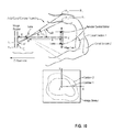
- FIG. 10 is a schematic of the mathematics and geometry used by a processor to detect a radial distance or position of the lateral portions of the laser light pattern intersecting a measured surface;
- FIG. 11 is a three-dimensional shape of a portion of an ear canal reconstructed by a computer shown in FIG. 1 ;
- FIG. 12 is a perspective view of ear anatomy used in a method for measuring a geometry of an ear saddle of another embodiment of the present invention.
- FIG. 13 is a schematic of a computer system of another embodiment of the present invention for optically determining surface geometries.
- embodiments of the present invention include a device 10 for scanning a body orifice or surface including a light source 12 and a wide angle lens 14 .
- the light from the light source is projected in a pattern 16 distal or adjacent to the wide angle lens 14 .
- the pattern 16 is within a focal surface 18 of the wide angle lens 14 .
- the pattern 16 intersects a surface of the body orifice, such as an ear canal, and defines a partial lateral portion 20 of the pattern extending along the surface.
- a processor 26 is configured to receive an image of the lateral portion 20 from the wide angle lens 14 and determine a position of the lateral portion in a coordinate system using a known focal surface of the wide angle lens 14 .
- known refers to known approximately within normal tolerances fit to achieve the desired resolution.
- the known focal surface has some thickness and variation to it that corresponds to the result of normal manufacturing tolerances.
- the device may further include a handheld probe 34 , an optical hardware assembly 66 , a tracking system 28 and a computer 68 .
- the optical hardware assembly 66 can be contained within the body of the handheld probe 34 .
- the body 30 of the patient defines any of a plurality of orifices or body surfaces that can be investigated by embodiments of the present invention for medical purposes.
- Body markers 38 or fiducials adorn the portion of the body 30 defining the surface or orifice of interest.
- a head band 72 extends around the head near the ear canal 70 and supports a plurality of retro-reflective spheres.
- ear canal 70 which has a small diameter (approximately 6 mm).
- the ear canal optionally has and at least one bend along its length.
- the probe 34 includes a handle 74 , a cable 76 , a probe shaft 40 , and a plurality of probe markers 38 .
- the cable 76 includes a light conductor 42 and a plurality of image conductors 44 and connects the probe 34 to the optical hardware assembly 66 .
- the image conductors may conduct the optical images, such as through a fiber optic line, or through communicating an electrical signal containing the image data.
- the term “conductor” therefore is used in its broadest sense herein to include conducting of any signal, analog or digital, power or information or data.
- a conductor may also represent wireless communication such as by an RF signal.
- the optical hardware assembly includes a fiberscope body, the light source 12 and a camera.
- the fiberscope body is connected via one of the image conductors 44 to the probe 34 .
- the camera is connected to the fiberscope body and receives images therefrom for navigation of the probe 34 within the body orifice.
- the light source in this case a laser light source, connects to the probe 34 via the light conductor 42 .
- the tracking system 28 includes a pair of cameras 78 spaced apart and pointed toward the probe markers 36 and the body marker 38 .
- the tracking system 28 may be an integrated system that is configured to track and report the position of objects within its coordinate system, or one marker relative to another, using on-board hardware and software.
- the processing functions may be distributed, such as within the computer system 68 of the embodiment illustrated in FIG. 1 .
- the computer system 68 is connected to the optical hardware assembly 66 and the tracking system 28 .
- the processor 26 Within the computer is the processor 26 and additional components described in more detail in FIG. 13 .
- the computer system is configured to receive data from the probe 34 , including data on the lateral portions 20 of the light pattern 16 intersecting surfaces of the body orifice, and data from the tracking system 28 , including position data of the probe 34 and the wearer's body relative to a coordinate system.
- the computer's processor 26 is configured to use the data to determine a three-dimensional shape of the body surfaces, such as the shape of the ear canal 70 , for use in building customized hearing aids.
- the probe 34 is shown in greater schematic detail and includes the probe markers 36 in the form of a plurality of retro-reflective tracking spheres within the field of view of the cameras 78 of the tracking system 28 .
- the probe markers 36 are used and the probe comprises three or more such probe markers.
- three spheres are the minimum needed to lock down all 6 degrees of freedom.
- Emitting from a distal end of the probe is the light pattern 16 (in this case a planar surface, but it could also be a cone of light, or a beam or some other surface shape) extending through the transparent side walls 58 of a cap 56 and forming one or more lateral portions 20 as it intersects the inner surfaces of the ear canal 70 .
- the probe 34 is advantageously sized to move within the ear canal 70 to capture several shapes that are communicated to the computer system 68 for assembly into the three-dimensional shape 32 .
- FIGS. 3A , 3 B, 3 C, 3 D, and 3 F are even more detailed views of the distal end of the probe 34 .
- the probe can optionally comprise one or more of the light conductor 42 , the image conductors 44 , the cap 56 , a reflector 48 , a mask 50 , a cone mirror 52 and a fiber scope 54 .
- the distal end of the probe 34 is shown in cross section with the wide angle lens 14 positioned proximal to ends of the fiber scope 54 and light conductor 42 carrying the laser light.
- the wide angle lens defines a field of view 46 as shown by the dotted lines. Extending back proximally from the lens is one of the image conductors 44 configured to carry the images or data on the partial lateral portion(s) 20 .
- the field of view of the illustrated embodiment is a full 150 degrees wherein the light pattern 16 may extend laterally out at right angles to the optical axis of the wide angle lens. Angles up to 180 degrees are possible but wider angles can be increasingly difficult to minimize distortion.
- the light conductor 42 and the distal end of the fiber scope 54 which includes a conductor(s) (such as a fiber optic bundle) for diffuse light and return conductor(s) for returning navigation images.
- a conductor(s) such as a fiber optic bundle
- the mirror 52 At the distal most tip of the light source 12 is positioned the mirror 52 having a conical shape and configured to redirect the laser light into the pattern 16 . If the conical shape is more or less than a 45 degree angle with respect to the axis of the laser light, the shape of the pattern 16 a conical surface. At 45 degrees, the shape is the planar surface 60 shown in FIG. 2 .
- the mask 50 is a planar sheet with a pair of holes, as shown in FIG. 3D , and is preferably constructed of a transparent material to block reflections from the redirected laser light back to the wide angle lens 14 that may not be representative of the surface being detected and measured.
- the holes allow for passage of the light conductor 42 transmitting the laser light to the cone mirror 52 and the image conductor 44 for the fiber scope 54 .
- the transparent side walls 58 and the cap 56 are configured to enclose and protect the distal portions of the probe 34 but at the same time allow passage of the laser light pattern 16 , diffuse navigation light from the fiber scope 54 and the images resulting and returning therefrom.
- the cap 56 may be, but does not need to be, transparent for the fiberscope.
- an opening in the cap 56 may allow passage and/or viewing by the fiberscope.
- the returned partial lateral portion 20 may only be a “C shape” that leaves out a portion blocked from visibility by the light conductor 42 and image conductor 44 .
- FIG. 4 shows an exploded view of a probe 34 of another embodiment of the present invention with the outer shaft 40 removed to better illustrate the function of the optical components.
- the cap 56 is assembled to the transparent side walls 58 which are formed by a short section of transparent cylindrical tube.
- the mirror 52 which is mounted in a mirror tube and affixed to the end of laser light conductor 42 .
- the laser light conductor 42 may also include a collimator function to generate a collimated beam for redirection into the pattern 16 by the cone mirror 52 .
- the fiberscope 54 has its distal end near the cone mirror 52 and extends proximally in a path adjacent to the light conductor 42 within the shaft 40 . Both the fiber scope 54 and the light conductor 52 bend around a CCD camera chip 80 and into the body of the probe 34 to pass through the cable 76 to the computer system 68 .
- the wide angle lens 14 and its image conductor 44 extend back from the cylindrical window 58 in a generally parallel relationship to the conductors 42 , 44 .
- the relative positioning of the optical components of the wide angle lens 14 is maintained in part by use of a pair of spacers 82 .
- the wide angle lens 14 is a plurality of optical lens elements that include the image conductor 14 returning the image of the lateral portions 20 to the CCD camera chip 80 mounted in the body of the probe as shown in FIG. 4 .
- a focusing screw 84 that when turned adjusts the focus of the wide angle lens 14 , thereby changing the position of its focal surface for improved accuracy within different body orifices and for compensating for manufacturing tolerances and for improved accuracy within a variety of orifices.
- Proximal to the focusing screw 84 is the CCD camera chip that receives the images of the lateral portions 20 and converts those images into pixel data for return to the computer 68 for processing.
- wide angle lens means any lens configured for a relatively wide field of view that will work in tortuous openings such as the ear canal 70 .
- a 63 degree angle results in a lens-focal surface offset about equal to the maximum diameter of the ear canal that can be scanned with a centered probe 34 .
- the focal surface of a 60 degree lens (a fairly standard sized wide angle lens) is equal to the diameter, resulting in a forward focal surface of about 6 mm, which is short enough to survive the second bend in an ear canal which is at about a 6 mm diameter. Therefore, for the purpose of ear canals, wide angle lenses are 60 degrees or greater.
- the device 10 may not need a fiber scope 54 and instead the wide angle lens 14 is used for the forward field of view.
- a beam splitter diverts the center of the wide angle lens field to a second camera that is focused further in front of the probe 34 and is configured to image the forward (nonlaser-lit) view.
- a diffuse light source may be provided to illuminate ahead of the probe 34 .
- a skin target is shown with partial lateral portions 20 of the pattern 16 projected thereon for the purpose of determining how the laser pattern 16 will project upon skin and its location be marked.
- a perpendicular section of one of the lateral portions shows that the light intensity (y-axis) varies in a bell-curve shape with the thickness (x-axis) of the section.
- the partial lateral portion 20 may include an edge 22 of the light pattern 16 or a ridge 24 of the light pattern. These landmarks may be used to determine the position of the lateral portion 20 in the coordinate system.
- one of the aforementioned landmarks could be found (such as by a ridge detecting function of the processor 26 ) or an inside edge of the lateral portion or an outside edge of the lateral portion. Or, an average of the inside and outside portions may be used.
- An advantage of the present invention is that the wide angle lens 14 can view relatively proximate lateral portions of the body surface with high precision due to overlap of its focal surface with the pattern 16 of laser light.
- the term “focal surface” as used herein refers to a thickness within a range of focus of the wide angle lens 14 that is capable of achieving a certain base line resolution, such as being able to discern a 50 micrometer feature or smaller. For example, lateral positioning of the pattern 16 within the focal surface allows one pixel to be equivalent to about 50 micrometers.
- the focal surface itself has a bell curve distribution of resolution that allows variations in overlap or thickness of the focal surface and the width of the lateral portion 20 which, as shown above, has its own curved distribution across its thickness.
- the wide angle lens 14 should have a reasonably low distortion threshold to meet the resolution goals.
- Most wide angle lenses can be as high as ⁇ 80 percent or ⁇ 60 percent distortion that would need to be compensated by improved accuracy in other areas such as placement of the focal surface and lateral portion 20 . Therefore, there is no set threshold although collectively the various components are preferably tuned to allow a 50 micrometer or better resolution for lateral distances from the optical axis of the wide angle lens 14 .
- the inventors have found that a distortion of better than ⁇ 40 percent works well with preferred fields of view mentioned herein for ear canal applications.
- the tracker or tracking system 28 is configured to determine a position of the probe 34 in the coordinate system and the body 30 of the patient in the coordinate system.
- the processor 26 is configured to use this information to determine the position of the probe 34 and its measurements relative to the body 30 .
- the tracking system 28 may include elements of a commercially available tracking system such as the POLARIS SPECTRA from NDI of Waterloo, Ontario, Canada.
- the system is a two camera system to allow three-dimensional position determination of objects in its field of view including the patient and the probe 34 through the probe markers 36 and the body markers 38 .
- the probe 34 and its laser pattern 16 are calibrated using a target placed in the field of view.
- the laser pattern 16 and the optics, including the wide angle lens 14 are perfect and that the probe 34 is rigid. This enables referencing of the laser pattern 16 directed to the coordinate system.
- the target includes a checkerboard 86 connected to a pair of optical markers 88 carefully aligned with the z-axis of the probe 34 .
- the relative location of 86 with respect to 88 is known by performing photogrammetry on the calibration object.
- the probe 34 is placed so that the projected laser pattern 16 is co-planar (to within tolerance) with the calibration grid (to within tolerance). This may be aided by a hole in the target that allows passage of the probe 34 . Positioning is established when the laser light pattern 16 smears across the surface of the target 86 .
- a tracking session is performed with the tracker 28 to establish the position of the checkerboard with the markers 88 and the position of the probe with the probe markers 36 . Then, while maintaining the relative relationship of the probe 34 and the checkerboard 86 , a lamp or light is shined on the checkerboard 86 and an image of it is collected through the wide angle lens 14 .
- the direction of the y-axis and z-axis relative to the tracker 28 is also noted to avoid axial direction errors.
- Calibration may also include non-planar light patterns wherein a checkerboard is exposed to the light pattern in several different orientations. The intersection of the light pattern lateral portion with the checkerboard lines allows a reconstruction of the shape of the non-planar light pattern with respect to the wide-angle lens. Using a target similar to that illustrated in FIG. 8 , it is possible to relate the reconstructed shape of the pattern into the coordinate system of the handheld.
- FIG. 9 shows the simulation of the calibration image.
- the distance from the optical markers 88 to each of the corners of the checkerboard 86 and the laser pattern 16 is coincident with the corners of grid points on the checkerboards.
- the three dimensional position of the laser hitting the surface may be interpolating to determine the nearest grid point of the checkerboard 86 . This information is then used fix the laser pattern within the coordinate system.
- the device 10 includes a processor 26 that's connected in communication with the wide angle lens 14 and is configured to perform several functions including: determining a position of the lateral portion 20 in the coordinate system determining the position of the lateral portion 20 using a known focal surface determining the position of a plurality of the lateral portions 20 in the coordinate system and a corresponding location of the coordinate system relative to the body 30 combining the lateral portions 20 together into a three-dimensional shape 32 of a body orifice (such as an ear canal) using the positions and the corresponding locations
- FIG. 10 schematically shows an embodiment for calculation of the radial distance of the lateral portion 20 from the optical axis of the probe 34 as implemented by the processor 26 .
- the position can be determined by triangulation, as shown in equations 1-7.
- a coordinate system for the scanner is oriented so that its Z axis is centered and fixed as the central axis of a scanning probe, looking end-on into the probe, here also referred to as the imaging axis.
- the ratio of the distance R from the imaging axis of a laser-illuminated point to the distance S between the laser plane and the lens is equal to that of the distance h from the center of the image sensor to the distance S′ between the image sensor surface and the lens.
- Magnification M is the ratio of S′ and S.
- the image sensor may be implemented in complementary-symmetry metallic-oxide-semiconductor (‘CMOS’) sensor, as a charge-coupled device (‘CCD’), or with other sensing technology as may occur to those of skill in the art.
- CMOS complementary-symmetry metallic-oxide-semiconductor
- CCD charge-coupled device
- a CMOS sensor can be operated in a snapshot readout mode or with a rolling shutter when the scan along the Z-axis is incremented or stepped synchronously to effect a readout of a complete frame. Similar incrementing or stepping may be used for a CCD operated with interlacing scans of image frames.
- FIG. 11 shows an exemplary three-dimensional shape 32 of an ear canal 92 constructed from a plurality of the lateral portions assembled using the processor 26 .
- the device 10 may be used to measure anatomical features well-suited to facilitate creation of a hearing aid. These features include a saddle 90 , ear canal 92 and concha bowl 94 .
- the ear canal 92 and concha bowl 94 are scanned as described above and the probe 34 is rotated so the laser pattern 16 falls upon the surface of the outside of the tragus 96 .
- the scan moves up the pinna 98 until the saddle point 100 is reached and the scan progresses 10 to 15 mm beyond the saddle point 100 .
- This data is transmitted to the processor 26 , along with the orifice data, to construct the three-dimensional shape 32 used to custom build the hearing aid.
- FIG. 13 a schematic diagram of a central server 500 , or similar network entity such as the computer 68 shown in FIG. 1 , configured to implement a system for measuring body surfaces according to one embodiment of the invention, is provided.
- the designation “central” merely serves to describe the common functionality the server provides for multiple clients or other computing devices and does not require or infer any centralized positioning of the server relative to other computing devices.
- the central server 500 may include a processor 510 (such as the processor 26 ) that communicates with other elements within the central server 500 via a system interface or bus 545 . Also included in the central server 500 may be a display device/input device 520 for receiving and displaying data.
- This display device/input device 520 may be, for example, a keyboard or pointing device that is used in combination with a monitor, or the CCD 80 or the tracker 28 shown in FIGS. 1 and 4 .
- the central server 500 may further include memory 505 , which may include both read only memory (ROM) 535 and random access memory (RAM) 530 .
- the server's ROM 535 may be used to store a basic input/output system 540 (BIOS), containing the basic routines that help to transfer information across the one or more networks.
- BIOS basic input/output system
- the central server 500 may include at least one storage device 515 , such as a hard disk drive, a floppy disk drive, a CD Rom drive, or optical disk drive, for storing information on various computer-readable media, such as a hard disk, a removable magnetic disk, or a CD-ROM disk.
- each of these storage devices 515 may be connected to the system bus 545 by an appropriate interface.
- the storage devices 515 and their associated computer-readable media may provide nonvolatile storage for a central server. It is important to note that the computer-readable media described above could be replaced by any other type of computer-readable media known in the art. Such media include, for example, magnetic cassettes, flash memory cards and digital video disks.
- a number of program modules may be stored by the various storage devices and within RAM 530 .
- Such program modules may include an operating system 550 and a plurality of one or more (N) modules 560 .
- the modules 560 may control certain aspects of the operation of the central server 500 , with the assistance of the processor 510 and the operating system 550 .
- the modules may perform the functions described above and illustrated by the figures and other materials disclosed herein.
- each block in the flowchart or block diagrams may represent a module, segment, or portion of code, which comprises one or more executable instructions for implementing the specified logical function(s).
- the functions noted in the block may occur out of the order noted in the figures. For example, two blocks shown in succession may, in fact, be executed substantially concurrently, or the blocks may sometimes be executed in the reverse order, depending upon the functionality involved.
- Advantages of the embodiments of the invention described herein include the relatively short distance (3 mm, 2 mm, 1 mm or less) of the pattern 16 and focal surface 18 extending past the probe 34 that allow it to image laterally in orifices with tortuous geometry, such as ear canals with a small diameter and where it is useful to scan 3 mm past a bend and also to image larger diameter ear canals and spaces without having to take multiple passes over that section of the canal.
- the low distortion of the wide angle lens 14 leads to high resolution when the laser pattern 16 is coincident with the focal surface 18 . This allows the resolution of 50 micrometers for a single pixel when other prior art systems have neighboring pixels a millimeter or more apart.
- Advantages particular to the creation of hearing aids include a solution that allows directly scanning of the ear instead of making a silicone mold. Quality, performance and fit are improved while reducing cost and increasing speed of production by capturing the shape and size of the ear canal for submission directly to the hearing aid manufacturer.
- Other medical applications include endoscopic surgery, dental impressions and the aforementioned industrial applications, such as inspection of various pipes, channels, tubing or other openings.
- a camera may be any kind of image sensor.
- the embodiment was chosen and described in order to best explain the principles of the invention and the practical application, and to enable others of ordinary skill in the art to understand the invention for various embodiments with various modifications as are suited to the particular use contemplated.
Abstract
Description
Claims (30)
Priority Applications (9)
| Application Number | Priority Date | Filing Date | Title |
|---|---|---|---|
| US13/417,767 US8900126B2 (en) | 2011-03-23 | 2012-03-12 | Optical scanning device |
| CA2844738A CA2844738A1 (en) | 2011-03-23 | 2012-03-20 | Optical scanning device |
| PCT/US2012/029806 WO2012129229A2 (en) | 2011-03-23 | 2012-03-20 | Optical scanning device |
| KR1020137027859A KR20140067970A (en) | 2011-03-23 | 2012-03-20 | Optical scanning device |
| EP12760319.9A EP2710805A4 (en) | 2011-03-23 | 2012-03-20 | Optical scanning device |
| AU2012231140A AU2012231140A1 (en) | 2011-03-23 | 2012-03-20 | Optical scanning device |
| JP2014501185A JP2014524751A (en) | 2011-03-23 | 2012-03-20 | Optical scanning device |
| CN201280024217.5A CN103828360A (en) | 2011-03-23 | 2012-03-20 | Optical scanning device |
| US14/538,994 US20150057533A1 (en) | 2011-03-23 | 2014-11-12 | Optical scanning device |
Applications Claiming Priority (2)
| Application Number | Priority Date | Filing Date | Title |
|---|---|---|---|
| US201161466863P | 2011-03-23 | 2011-03-23 | |
| US13/417,767 US8900126B2 (en) | 2011-03-23 | 2012-03-12 | Optical scanning device |
Related Child Applications (1)
| Application Number | Title | Priority Date | Filing Date |
|---|---|---|---|
| US14/538,994 Continuation US20150057533A1 (en) | 2011-03-23 | 2014-11-12 | Optical scanning device |
Publications (2)
| Publication Number | Publication Date |
|---|---|
| US20120281071A1 US20120281071A1 (en) | 2012-11-08 |
| US8900126B2 true US8900126B2 (en) | 2014-12-02 |
Family
ID=46880001
Family Applications (2)
| Application Number | Title | Priority Date | Filing Date |
|---|---|---|---|
| US13/417,767 Expired - Fee Related US8900126B2 (en) | 2011-03-23 | 2012-03-12 | Optical scanning device |
| US14/538,994 Abandoned US20150057533A1 (en) | 2011-03-23 | 2014-11-12 | Optical scanning device |
Family Applications After (1)
| Application Number | Title | Priority Date | Filing Date |
|---|---|---|---|
| US14/538,994 Abandoned US20150057533A1 (en) | 2011-03-23 | 2014-11-12 | Optical scanning device |
Country Status (8)
| Country | Link |
|---|---|
| US (2) | US8900126B2 (en) |
| EP (1) | EP2710805A4 (en) |
| JP (1) | JP2014524751A (en) |
| KR (1) | KR20140067970A (en) |
| CN (1) | CN103828360A (en) |
| AU (1) | AU2012231140A1 (en) |
| CA (1) | CA2844738A1 (en) |
| WO (1) | WO2012129229A2 (en) |
Cited By (3)
| Publication number | Priority date | Publication date | Assignee | Title |
|---|---|---|---|---|
| US20130338436A1 (en) * | 2012-06-13 | 2013-12-19 | Boston Scientific Scimed, Inc. | Medical device visualization system |
| US20160051134A1 (en) * | 2014-08-19 | 2016-02-25 | United Sciences, Llc | Guidance of three-dimensional scanning device |
| US11647902B2 (en) * | 2019-04-05 | 2023-05-16 | University Of Utah Research Foundation | Otoscope |
Families Citing this family (26)
| Publication number | Priority date | Publication date | Assignee | Title |
|---|---|---|---|---|
| US8900126B2 (en) | 2011-03-23 | 2014-12-02 | United Sciences, Llc | Optical scanning device |
| US8900125B2 (en) * | 2012-03-12 | 2014-12-02 | United Sciences, Llc | Otoscanning with 3D modeling |
| US20150038849A1 (en) * | 2013-08-02 | 2015-02-05 | United Sciences, Llc | Methods for Reducing One or More Symptoms of Temporomandibular Joint Disorder |
| US20150038871A1 (en) * | 2013-08-02 | 2015-02-05 | United Sciences, Llc | In-Ear Proprioceptive for Relieving Temporomandibular Joint-Related Symptoms |
| US20150039087A1 (en) * | 2013-08-02 | 2015-02-05 | United Sciences, Llc | Method of Designing Custom Device for Alleviating Temporomandibular Joint-Related Symptoms |
| US20150035943A1 (en) * | 2013-08-02 | 2015-02-05 | United Sciences, Llc | In-Ear Orthotic for Relieving Temporomandibular Joint-Related Symptoms |
| US20150098636A1 (en) * | 2013-10-09 | 2015-04-09 | United Sciences, Llc | Integrated tracking with fiducial-based modeling |
| US20150097931A1 (en) * | 2013-10-09 | 2015-04-09 | United Sciences, Llc. | Calibration of 3d scanning device |
| US9042589B2 (en) | 2013-10-24 | 2015-05-26 | Logitech Europe, S.A. | Custom fit in-ear monitors utilizing a single piece driver module |
| US20170071473A1 (en) * | 2014-04-25 | 2017-03-16 | Koninklijke Philips N.V. | Optical sensor for a catheter |
| KR20170012487A (en) | 2014-05-30 | 2017-02-02 | 레볼 테크놀로지스 인코포레이티드 | A customizable ear insert |
| KR101638477B1 (en) * | 2014-09-19 | 2016-07-11 | 주식회사 고영테크놀러지 | Optical tracking system and registration method for coordinate system in optical tracking system |
| US10621765B2 (en) * | 2015-07-07 | 2020-04-14 | Idex Asa | Image reconstruction |
| US10861604B2 (en) * | 2016-05-05 | 2020-12-08 | Advinow, Inc. | Systems and methods for automated medical diagnostics |
| JP6735899B2 (en) * | 2016-07-13 | 2020-08-05 | 株式会社ディーディーエスDds Company | Three-dimensional scanner and artifact processing device using it |
| US10097817B2 (en) * | 2016-08-03 | 2018-10-09 | MEGAFORCE COMPANY LlMlTED | Double-image projection device projecting double images onto 3-dimensional ear canal model |
| US11026581B2 (en) * | 2016-09-30 | 2021-06-08 | Industrial Technology Research Institute | Optical probe for detecting biological tissue |
| US11164679B2 (en) | 2017-06-20 | 2021-11-02 | Advinow, Inc. | Systems and methods for intelligent patient interface exam station |
| DE112019000337T5 (en) | 2018-01-03 | 2020-09-17 | Logitech Europe S.A. | DEVICE AND METHOD FOR MANUFACTURING A TAILOR-MADE EAR CUP |
| US11348688B2 (en) | 2018-03-06 | 2022-05-31 | Advinow, Inc. | Systems and methods for audio medical instrument patient measurements |
| CN108759668B (en) * | 2018-05-31 | 2020-06-12 | 武汉中观自动化科技有限公司 | Tracking type three-dimensional scanning method and system in vibration environment |
| US11154188B2 (en) * | 2019-06-20 | 2021-10-26 | Cilag Gmbh International | Laser mapping imaging and videostroboscopy of vocal cords |
| US11156748B2 (en) * | 2019-09-18 | 2021-10-26 | Lenovo (Singapore) Pte. Ltd. | Omnidirectional structured light projection |
| US11425479B2 (en) | 2020-05-26 | 2022-08-23 | Logitech Europe S.A. | In-ear audio device with interchangeable faceplate |
| DE102021120835A1 (en) | 2021-08-10 | 2023-02-16 | Smart Optics Sensortechnik Gmbh | Method and system for acquiring 3D surface data of an object to be measured |
| WO2023150435A2 (en) * | 2022-02-02 | 2023-08-10 | The General Hospital Corporation | An ultra-flexible miniature optical coherence tomography catheter and imaging method for endomicroscopy of the inner ear |
Citations (187)
| Publication number | Priority date | Publication date | Assignee | Title |
|---|---|---|---|---|
| US4185918A (en) | 1975-08-27 | 1980-01-29 | Solid Photography Inc. | Arrangement for sensing the characteristics of a surface and determining the position of points thereon |
| US4396945A (en) | 1981-08-19 | 1983-08-02 | Solid Photography Inc. | Method of sensing the position and orientation of elements in space |
| US4434800A (en) | 1981-06-10 | 1984-03-06 | National Research Development Corporation | Tympanometric apparatus |
| US4575805A (en) | 1980-12-24 | 1986-03-11 | Moermann Werner H | Method and apparatus for the fabrication of custom-shaped implants |
| US4585349A (en) | 1983-09-12 | 1986-04-29 | Battelle Memorial Institute | Method of and apparatus for determining the position of a device relative to a reference |
| US4622967A (en) | 1984-09-13 | 1986-11-18 | Schachar Ronald A | Auricular instrument |
| US4637715A (en) | 1983-09-01 | 1987-01-20 | Rikagaku Kenkyusho | Optical distance measuring apparatus |
| US4645348A (en) | 1983-09-01 | 1987-02-24 | Perceptron, Inc. | Sensor-illumination system for use in three-dimensional measurement of objects and assemblies of objects |
| US4705401A (en) | 1985-08-12 | 1987-11-10 | Cyberware Laboratory Inc. | Rapid three-dimensional surface digitizer |
| US4774403A (en) | 1987-03-30 | 1988-09-27 | Harvey Industries, Inc. | Triangulation-type position measuring device |
| US4821117A (en) | 1986-11-12 | 1989-04-11 | Kabushiki Kaisha Toshiba | Endoscopic system for producing fluorescent and visible images |
| US4885634A (en) | 1987-10-27 | 1989-12-05 | Olympus Optical Co., Ltd. | Endoscope apparatus capable of monochrome display with respect to specific wavelength regions in the visible region |
| US4967092A (en) | 1988-05-17 | 1990-10-30 | Societe Anonyme Dite Hispano-Suiza | Apparatus for optically checking the inner profile of a tube or bore |
| US4986262A (en) | 1987-03-31 | 1991-01-22 | Kabushiki Kaisha Toshiba | Measuring endoscope |
| US5044373A (en) | 1989-02-01 | 1991-09-03 | Gn Danavox A/S | Method and apparatus for fitting of a hearing aid and associated probe with distance measuring means |
| US5056204A (en) | 1989-05-17 | 1991-10-15 | Ascom Audiosys Ag | Method of producing hearing aids |
| US5200819A (en) | 1988-05-27 | 1993-04-06 | The University Of Connecticut | Multi-dimensional imaging system for endoscope |
| US5218427A (en) | 1991-09-06 | 1993-06-08 | Koch Stephen K | Ranging system for three-dimensional object digitizing |
| US5280378A (en) | 1990-10-19 | 1994-01-18 | I.L. Med, Inc. | Cyclically scanned medical laser |
| US5294940A (en) | 1991-02-06 | 1994-03-15 | Dale A. Wennagel | Pulsed laser optical display device |
| US5419312A (en) | 1993-04-20 | 1995-05-30 | Wildflower Communications, Inc. | Multi-function endoscope apparatus |
| US5432543A (en) | 1992-03-05 | 1995-07-11 | Olympus Optical Co., Ltd. | Endoscopic image processing device for estimating three-dimensional shape of object based on detection of same point on a plurality of different images |
| US5436655A (en) | 1991-08-09 | 1995-07-25 | Olympus Optical Co., Ltd. | Endoscope apparatus for three dimensional measurement for scanning spot light to execute three dimensional measurement |
| US5487012A (en) | 1990-12-21 | 1996-01-23 | Topholm & Westermann Aps | Method of preparing an otoplasty or adaptive earpiece individually matched to the shape of an auditory canal |
| US5546189A (en) | 1994-05-19 | 1996-08-13 | View Engineering, Inc. | Triangulation-based 3D imaging and processing method and system |
| US5605531A (en) | 1994-04-08 | 1997-02-25 | Tilane Corporation | Apparatus for use with endoscopy and fluoroscopy for automatic switching between video modes |
| US5658235A (en) | 1995-03-31 | 1997-08-19 | Medrx, Inc. | Video otoscope and optical lens system therefor |
| US5702249A (en) | 1995-05-19 | 1997-12-30 | Cooper; David H. | Modular intra-oral imaging system video camera |
| US5714832A (en) | 1996-03-15 | 1998-02-03 | Hughes Electronics | Miniature grating device |
| US5733246A (en) | 1994-05-13 | 1998-03-31 | Precision Optics Corporation | Viewing scope with image intensification |
| US5738633A (en) | 1993-12-10 | 1998-04-14 | Madsen Electronics A/S | Oto-acoustic emission analyser |
| US5740802A (en) | 1993-04-20 | 1998-04-21 | General Electric Company | Computer graphic and live video system for enhancing visualization of body structures during surgery |
| US5747789A (en) | 1993-12-01 | 1998-05-05 | Dynamics Imaging, Inc. | Method for investigation of distribution of physiological components in human body tissues and apparatus for its realization |
| US5753931A (en) | 1995-07-13 | 1998-05-19 | Nike, Inc. | Object imaging device and method using line striping |
| US5784098A (en) | 1995-08-28 | 1998-07-21 | Olympus Optical Co., Ltd. | Apparatus for measuring three-dimensional configurations |
| US5825495A (en) | 1995-02-27 | 1998-10-20 | Lockheed Martin Corporation | Bright field illumination system |
| US5831601A (en) | 1995-06-07 | 1998-11-03 | Nview Corporation | Stylus position sensing and digital camera with a digital micromirror device |
| US5840017A (en) | 1995-08-03 | 1998-11-24 | Asahi Kogaku Kogyo Kabushiki Kaisha | Endoscope system |
| US5847832A (en) | 1996-03-15 | 1998-12-08 | Hughes Aircraft Company | Moire topographic measurement |
| US5883385A (en) | 1995-11-09 | 1999-03-16 | Kabushiki Kaisha Toshiba | Multibeam scanning method and apparatus with positional adjustment features |
| US5891016A (en) | 1995-11-09 | 1999-04-06 | Asahi Kogaku Kogyo Kabushiki Kaisha | Fluorescence endoscope having an exciting light filter and a fluorescence filter |
| US5895927A (en) | 1995-06-30 | 1999-04-20 | The United States Of America As Represented By The Secretary Of The Air Force | Electro-optic, noncontact, interior cross-sectional profiler |
| US5897494A (en) | 1997-01-31 | 1999-04-27 | The Board Of Trustees Of The University Of Arkansas | Vibrometer |
| US5926388A (en) | 1994-12-09 | 1999-07-20 | Kimbrough; Thomas C. | System and method for producing a three dimensional relief |
| US5936628A (en) | 1991-08-06 | 1999-08-10 | Canon Kabushiki Kaisha | Three-dimensional model processing method, and apparatus therefor |
| US5978092A (en) | 1997-12-02 | 1999-11-02 | Brown; Thomas Mattingly | Peripheral viewing optical scanner for three dimensional surface measurement |
| US6028672A (en) | 1996-09-30 | 2000-02-22 | Zheng J. Geng | High speed three dimensional imaging method |
| US6044170A (en) | 1996-03-21 | 2000-03-28 | Real-Time Geometry Corporation | System and method for rapid shape digitizing and adaptive mesh generation |
| US6069698A (en) | 1997-08-28 | 2000-05-30 | Olympus Optical Co., Ltd. | Optical imaging apparatus which radiates a low coherence light beam onto a test object, receives optical information from light scattered by the object, and constructs therefrom a cross-sectional image of the object |
| US6081612A (en) | 1997-02-28 | 2000-06-27 | Electro Optical Sciences Inc. | Systems and methods for the multispectral imaging and characterization of skin tissue |
| US6110106A (en) | 1998-06-24 | 2000-08-29 | Biomax Technologies, Inc. | Endoscopes and methods relating to direct viewing of a target tissue |
| US6179777B1 (en) | 1997-11-27 | 2001-01-30 | Asahi Kogaku Kogyo Kabushiki Kaisha | Fluorescent diagnosing apparatus including optical path switching member |
| US6186944B1 (en) | 1998-11-25 | 2001-02-13 | Jory Tsai | Medical inspection device |
| US6217510B1 (en) | 1997-10-02 | 2001-04-17 | Olympus Optical Co., Ltd. | Endoscopes and endoscope devices which image regular observation images and fluorescent images as well as which provide easier operation of treatment tools |
| US6292263B1 (en) | 1998-02-18 | 2001-09-18 | Minolta Co., Ltd. | Three-dimensional measuring apparatus |
| US6293911B1 (en) | 1996-11-20 | 2001-09-25 | Olympus Optical Co., Ltd. | Fluorescent endoscope system enabling simultaneous normal light observation and fluorescence observation in infrared spectrum |
| US6319199B1 (en) | 1998-10-26 | 2001-11-20 | David M. Sheehan | Portable data collection device |
| US6327041B1 (en) | 1998-06-05 | 2001-12-04 | Dentalmatic Technologies, Inc. | Method and device for opto-electrical acquisition of shapes by axial illumination |
| US20010051766A1 (en) | 1999-03-01 | 2001-12-13 | Gazdzinski Robert F. | Endoscopic smart probe and method |
| US20010055462A1 (en) * | 2000-06-19 | 2001-12-27 | Seibel Eric J. | Medical imaging, diagnosis, and therapy using a scanning single optical fiber system |
| US6361489B1 (en) | 1998-11-25 | 2002-03-26 | Jory Tsai | Medical inspection device |
| US6377865B1 (en) | 1998-02-11 | 2002-04-23 | Raindrop Geomagic, Inc. | Methods of generating three-dimensional digital models of objects by wrapping point cloud data points |
| US6383133B1 (en) | 1999-11-09 | 2002-05-07 | Dwight T. Jones | Otoscope kit |
| US6393431B1 (en) | 1997-04-04 | 2002-05-21 | Welch Allyn, Inc. | Compact imaging instrument system |
| US6450970B1 (en) | 1999-11-16 | 2002-09-17 | Ron Mahler | Method and device for diagnosing an inflammatory process |
| US6459493B1 (en) | 1995-06-16 | 2002-10-01 | Sony Corporation | Apparatus for measuring surface form |
| US6470124B1 (en) | 1998-09-15 | 2002-10-22 | Assistance Publique - Hopitaux De Paris | Device for observation inside a body providing improved quality of observation |
| US6471636B1 (en) | 1994-09-21 | 2002-10-29 | Asahi Kogaku Kogyo Kabushiki Kaisha | Fluorescence diagnosis endoscope system |
| US20020161282A1 (en) | 1999-01-26 | 2002-10-31 | Newton Laboratories, Inc. | Autofluorescence imaging system for endoscopy |
| US6532299B1 (en) | 2000-04-28 | 2003-03-11 | Orametrix, Inc. | System and method for mapping a surface |
| US20030074174A1 (en) | 2000-10-06 | 2003-04-17 | Ping Fu | Manufacturing methods and systems for rapid production of hearing-aid shells |
| US6573513B2 (en) | 2000-01-17 | 2003-06-03 | Fuji Photo Film Co., Ltd. | Fluorescence imaging apparatus |
| US20030139658A1 (en) | 2002-01-21 | 2003-07-24 | Nick Collier | Method for the reconstruction of the geometry of the inner surface of a cavity |
| US20030139673A1 (en) | 2002-01-18 | 2003-07-24 | Vivenzio Robert L. | Illumination system |
| US6602186B1 (en) | 1999-11-11 | 2003-08-05 | Pentax Corporation | Electronic endoscope system |
| US6603552B1 (en) | 1999-12-22 | 2003-08-05 | Xillix Technologies Corp. | Portable system for detecting skin abnormalities based on characteristic autofluorescence |
| US20030164952A1 (en) * | 2000-08-25 | 2003-09-04 | Nikolaj Deichmann | Method and apparatus for three-dimensional optical scanning of interior surfaces |
| US20030171655A1 (en) | 2002-03-08 | 2003-09-11 | Newman Richard W. | Combination otoscope |
| US6626825B2 (en) | 1998-11-25 | 2003-09-30 | Jory Tsai | Medical inspection device |
| US20030210812A1 (en) * | 2002-02-26 | 2003-11-13 | Ali Khamene | Apparatus and method for surgical navigation |
| US6675040B1 (en) | 1991-01-28 | 2004-01-06 | Sherwood Services Ag | Optical object tracking system |
| US6679839B2 (en) | 2000-06-30 | 2004-01-20 | Inner Vision Imaging, Llc | Endoscope |
| US20040107080A1 (en) | 2001-03-02 | 2004-06-03 | Nikolaj Deichmann | Method for modelling customised earpieces |
| US6753966B2 (en) | 2000-03-10 | 2004-06-22 | Textron Systems Corporation | Optical probes and methods for spectral analysis |
| US20040122787A1 (en) | 2002-12-18 | 2004-06-24 | Avinash Gopal B. | Enhanced computer-assisted medical data processing system and method |
| US20040136010A1 (en) | 2001-05-17 | 2004-07-15 | Jensen Preben Damgard | Method and apparatus for obtaining geometrical data relating to the ear canal of the human body |
| US20050068544A1 (en) | 2003-09-25 | 2005-03-31 | Gunter Doemens | Panoramic scanner |
| US6920414B2 (en) | 2001-03-26 | 2005-07-19 | Widex A/S | CAD/CAM system for designing a hearing aid |
| US6918538B2 (en) | 2002-12-18 | 2005-07-19 | Symbol Technologies, Inc. | Image scanning device having a system for determining distance to a target |
| US6937348B2 (en) | 2000-01-28 | 2005-08-30 | Genex Technologies, Inc. | Method and apparatus for generating structural pattern illumination |
| US20060133634A1 (en) | 2004-11-24 | 2006-06-22 | Christian Berg | Method of obtaining a three-dimensional image of the outer ear canal |
| US7068825B2 (en) * | 1999-03-08 | 2006-06-27 | Orametrix, Inc. | Scanning system and calibration method for capturing precise three-dimensional information of objects |
| US7110124B2 (en) | 2001-05-17 | 2006-09-19 | Oticon A/S | Method and apparatus for obtaining geometrical data relating to a canal |
| US7137948B2 (en) | 1998-11-25 | 2006-11-21 | Jory Tsai | Medical inspection device |
| US20060282009A1 (en) | 2003-06-13 | 2006-12-14 | Ake Oberg | Device for measuring physical properties of the tympanic membrane |
| US7162323B2 (en) | 2004-04-05 | 2007-01-09 | Hearing Aid Express, Inc. | Decentralized method for manufacturing hearing aid devices |
| US20070035707A1 (en) | 2005-06-20 | 2007-02-15 | Digital Display Innovations, Llc | Field sequential light source modulation for a digital display system |
| US7179222B2 (en) | 1996-11-20 | 2007-02-20 | Olympus Corporation | Fluorescent endoscope system enabling simultaneous achievement of normal light observation based on reflected light and fluorescence observation based on light with wavelengths in infrared spectrum |
| US20070112273A1 (en) | 2003-11-18 | 2007-05-17 | Chameleon Medical Innovation, Ltd. | Measurement system and method for use in determining the patient's condition |
| US20070153296A1 (en) | 2005-12-13 | 2007-07-05 | Siemens Aktiengesellschaft | Optical measuring device for measuring a cavity |
| US20070156021A1 (en) * | 2005-09-14 | 2007-07-05 | Bradford Morse | Remote imaging apparatus having an adaptive lens |
| US7251025B2 (en) | 2001-05-17 | 2007-07-31 | Oticon A/S | Method and apparatus for obtaining position data relating to a probe in the ear canal |
| US7258663B2 (en) | 1999-05-18 | 2007-08-21 | Olympus Corporation | Endoscope system with irradiated light switching feature |
| US20070237306A1 (en) | 2006-01-17 | 2007-10-11 | Jones Sharon D | Laser imaging apparatus with variable patient positioning |
| US20070270647A1 (en) | 2006-05-19 | 2007-11-22 | Ams Research Corporation | Handle for Multifunction Endoscope |
| US7311723B2 (en) | 2003-07-11 | 2007-12-25 | University Of Washington | Scanning laser device and methods of use |
| US20080045800A2 (en) | 2004-09-24 | 2008-02-21 | Mina Farr | Solid state illumination for endoscopy |
| US20080045799A1 (en) | 2006-04-10 | 2008-02-21 | Peter Whitehead | Multipurpose diseased tissue detection devices, systems, and methods |
| US20080058629A1 (en) | 2006-08-21 | 2008-03-06 | University Of Washington | Optical fiber scope with both non-resonant illumination and resonant collection/imaging for multiple modes of operation |
| US7341557B2 (en) | 2000-07-14 | 2008-03-11 | Novadaq Technologies Inc. | Compact fluorescence endoscopy video system |
| US20080081950A1 (en) * | 2006-09-28 | 2008-04-03 | Jenlab Gmbh | Method and arrangement for high-resolution microscope imaging or cutting in laser endoscopy |
| US7371218B2 (en) | 2002-01-17 | 2008-05-13 | Siemens Medical Solutions Usa, Inc. | Immersive portable ultrasound system and method |
| US20080119693A1 (en) | 2004-04-21 | 2008-05-22 | Acclarent, Inc. | Methods and Apparatus for Treating Disorders of the Ear, Nose and Throat |
| US20080146915A1 (en) | 2006-10-19 | 2008-06-19 | Mcmorrow Gerald | Systems and methods for visualizing a cannula trajectory |
| US7399181B2 (en) | 2000-11-08 | 2008-07-15 | Aepsilon Gmbh | Surface mapping and generating devices and methods for surface mapping and surface generation |
| US20080208006A1 (en) | 2004-09-24 | 2008-08-28 | Mina Farr | Opto-electronic illumination and vision module for endoscopy |
| US20080208297A1 (en) | 2005-01-25 | 2008-08-28 | Allux Medical, Inc. | Optical Therapy Devices, Systems, Kits and Methods for Providing Therapy to a body Cavity |
| US7421140B2 (en) | 2001-11-21 | 2008-09-02 | Shraga Rottem | Method and system for enhancing the quality of device images |
| US7419467B2 (en) | 1998-11-25 | 2008-09-02 | M3 Electronics, Inc. | Medical inspection device |
| US7440121B2 (en) | 2006-09-20 | 2008-10-21 | Lawrence Livermore National Security, Llc | Optically measuring interior cavities |
| US7446885B2 (en) | 2002-05-15 | 2008-11-04 | Icos Vision Systems N.V. | Device for measuring in three dimensions a topographical shape of an object |
| US20080275483A1 (en) | 2004-04-21 | 2008-11-06 | Acclarent, Inc. | Methods and Apparatus for Treating Disorders of the Ear Nose and Throat |
| US7448753B1 (en) | 2005-07-19 | 2008-11-11 | Chinnock Randal B | Portable Digital Medical Camera for Capturing Images of the Retina or the External Auditory Canal, and Methods of Use |
| US20080281167A1 (en) | 2002-08-20 | 2008-11-13 | Welch Allyn, Inc. | Diagnostic instrument workstation |
| US20090018465A1 (en) | 2006-01-06 | 2009-01-15 | Phonak Ag | Method and system for reconstructing the three-dimensional shape of the surface of at least a portion of an ear canal and/or of a concha |
| US20090021818A1 (en) * | 2007-07-20 | 2009-01-22 | Ethicon Endo-Surgery, Inc. | Medical scanning assembly with variable image capture and display |
| US20090028407A1 (en) | 2005-11-23 | 2009-01-29 | University Of Washington | Scanning beam with variable sequential framing using interrupted scanning resonance |
| US7490085B2 (en) | 2002-12-18 | 2009-02-10 | Ge Medical Systems Global Technology Company, Llc | Computer-assisted data processing system and method incorporating automated learning |
| US7544163B2 (en) | 2003-09-26 | 2009-06-09 | Tidal Photonics, Inc. | Apparatus and methods relating to expanded dynamic range imaging endoscope systems |
| US7553020B2 (en) | 2006-09-29 | 2009-06-30 | Welch Allyn, Inc. | Medical diagnostic instrument with variable focus liquid lens |
| US20090189972A1 (en) | 2005-07-12 | 2009-07-30 | Harris Michael D | System and method for video medical examination and real time transmission to remote locations |
| US7583872B2 (en) | 2007-04-05 | 2009-09-01 | University Of Washington | Compact scanning fiber device |
| US20090221920A1 (en) | 2008-01-18 | 2009-09-03 | Boppart Stephen A | Low-coherence interferometry and optical coherence tomography for image-guided surgical treatment of solid tumors |
| US20090292168A1 (en) | 2004-09-24 | 2009-11-26 | Vivid Medical | Wavelength multiplexing endoscope |
| US20090312638A1 (en) | 2006-07-17 | 2009-12-17 | Signostics Pty Ltd | medical diagnostic device |
| US20090318758A1 (en) | 2004-09-24 | 2009-12-24 | Vivid Medical, Inc. | Pluggable vision module and portable display for endoscopy |
| US20100020333A1 (en) | 2007-02-02 | 2010-01-28 | Martin Kunz | Refractive production of a concentrically fanned structured bundle of light beams, optical, measuring device with refractive defection element |
| US20100060718A1 (en) | 2006-11-17 | 2010-03-11 | Frank Forster | Measuring a hollow space by means of cylindrically symmetrical triangulation |
| US7742635B2 (en) | 2005-09-22 | 2010-06-22 | 3M Innovative Properties Company | Artifact mitigation in three-dimensional imaging |
| US20100191144A1 (en) | 2009-01-23 | 2010-07-29 | Path Medical Gmbh | Ear canal obstruction detecting acoustical stimulation ear probe |
| US20100198009A1 (en) | 2004-09-24 | 2010-08-05 | Vivid Medical, Inc. | Disposable endoscope and portable display |
| US20100231513A1 (en) | 2008-12-03 | 2010-09-16 | Analog Devices, Inc. | Position measurement systems using position sensitive detectors |
| US7801584B2 (en) | 2003-05-01 | 2010-09-21 | Given Imaging Ltd. | Panoramic field of view imaging device |
| US20100239126A1 (en) | 2009-03-23 | 2010-09-23 | Siemens Medical Instruments Pte. Ltd. | Apparatus and method for measuring a distance to an eardrum |
| US7802909B2 (en) | 2005-09-20 | 2010-09-28 | Noble Marketing, Inc. | Multifunctional medical examination instrument |
| US7813591B2 (en) | 2006-01-20 | 2010-10-12 | 3M Innovative Properties Company | Visual feedback of 3D scan parameters |
| US7835925B2 (en) | 2001-02-20 | 2010-11-16 | The Procter & Gamble Company | System for improving the management of the health of an individual and related methods |
| US20100296664A1 (en) | 2009-02-23 | 2010-11-25 | Verto Medical Solutions Llc | Earpiece system |
| WO2010140074A1 (en) | 2009-06-01 | 2010-12-09 | Koninklijke Philips Electronics N.V. | Distance-based position tracking method and system |
| US20110009694A1 (en) * | 2009-07-10 | 2011-01-13 | Schultz Eric E | Hand-held minimally dimensioned diagnostic device having integrated distal end visualization |
| US20110026037A1 (en) | 2009-07-28 | 2011-02-03 | Frank Forster | Apparatus and method for recording the shape of an ear section |
| US20110028790A1 (en) | 2004-09-24 | 2011-02-03 | Vivid Medical, Inc. | Disposable endoscopic access device and portable display |
| US7925333B2 (en) | 2007-08-28 | 2011-04-12 | Ethicon Endo-Surgery, Inc. | Medical device including scanned beam unit with operational control features |
| US7937253B2 (en) | 2004-03-05 | 2011-05-03 | The Procter & Gamble Company | Virtual prototyping system and method |
| US20110102763A1 (en) | 2009-10-30 | 2011-05-05 | Microvision, Inc. | Three Dimensional Imaging Device, System and Method |
| US7949385B2 (en) | 2003-03-11 | 2011-05-24 | Siemens Medical Solutions Usa, Inc. | System and method for reconstruction of the human ear canal from optical coherence tomography scans |
| US20110130652A1 (en) | 2009-11-18 | 2011-06-02 | The Board Of Trustees Of The University Of Illinois | Apparatus for biomedical imaging |
| US7955255B2 (en) | 2006-04-20 | 2011-06-07 | Boston Scientific Scimed, Inc. | Imaging assembly with transparent distal cap |
| US20110137118A1 (en) | 2009-10-06 | 2011-06-09 | Apple Biomedical, Inc. | Medical inspection device |
| US7996068B2 (en) | 2007-03-14 | 2011-08-09 | The Board Of Trustees Of The Leland Stanford Junior University | Surgical method and apparatus for identification of fluorescence |
| US8035637B2 (en) | 2006-01-20 | 2011-10-11 | 3M Innovative Properties Company | Three-dimensional scan recovery |
| US8107086B2 (en) | 2008-07-24 | 2012-01-31 | Massachusetts Institute Of Technology | Three-dimensional imaging using absorption |
| US20120039493A1 (en) | 2008-09-22 | 2012-02-16 | SoudBeam LLC | Transducer devices and methods for hearing |
| US20120057734A1 (en) | 2008-07-23 | 2012-03-08 | Asius Technologies, Llc | Hearing Device System and Method |
| US8169470B2 (en) | 2005-08-31 | 2012-05-01 | Olympus Medical Systems Corp. | Optical imaging device having illumination light filter section |
| US20120140301A1 (en) | 2007-11-12 | 2012-06-07 | Cornell University | Multi-path, multi-magnification, non-confocal fluorescence emission endoscopy apparatus and methods |
| US8206290B2 (en) | 2009-10-08 | 2012-06-26 | Apple Biomedical, Inc. | Medical inspection device |
| US8212884B2 (en) | 2007-05-22 | 2012-07-03 | University Of Washington | Scanning beam device having different image acquisition modes |
| US8228368B2 (en) | 2008-04-26 | 2012-07-24 | Intuitive Surgical Operations, Inc. | Augmented stereoscopic visualization for a surgical robot using a captured fluorescence image and captured stereoscopic visible images |
| US20120187190A1 (en) | 2005-03-11 | 2012-07-26 | Hand Held Products, Inc. | Image reader having image sensor array |
| US20120191078A1 (en) * | 2011-01-21 | 2012-07-26 | Yadlowsky Michael J | Combined surgical endoprobe for optical coherence tomography, illumination or photocoagulation |
| US8239001B2 (en) | 2003-10-17 | 2012-08-07 | Medtronic Navigation, Inc. | Method and apparatus for surgical navigation |
| US8249461B2 (en) | 2007-08-13 | 2012-08-21 | Oticon A/S | Method of and system for positioning first and second devices relative to each other |
| US8271069B2 (en) | 2003-10-17 | 2012-09-18 | Medtronic Navigation, Inc. | Method and apparatus for surgical navigation |
| WO2012129229A2 (en) | 2011-03-23 | 2012-09-27 | 3Dm Systems, Inc. | Optical scanning device |
| US20120310098A1 (en) | 2010-02-12 | 2012-12-06 | Koninklijke Philips Electronics N.V. | Laser enhanced reconstruction of 3d surface |
| US20120327427A1 (en) | 2008-07-24 | 2012-12-27 | Hart Douglas P | Inflatable membrane with hazard mitigation |
| US20120327287A1 (en) | 2007-12-06 | 2012-12-27 | U.S. Government As Represented By The Secretary Of The Army | Method and system for producing image frames using quantum properties |
| US20120327426A1 (en) | 2008-07-24 | 2012-12-27 | Hart Douglas P | Inflatable membrane having non-uniform inflation characteristic |
| US20130003078A1 (en) | 2008-07-24 | 2013-01-03 | Hart Douglas P | Three dimensional scanning using membrane with optical features |
| US20130002426A1 (en) | 2008-07-24 | 2013-01-03 | Hart Douglas P | Enhanced sensors in three dimensional scanning system |
| US20130002824A1 (en) | 2008-07-24 | 2013-01-03 | Hart Douglas P | Integrated otoscope and three dimensional scanning system |
| US20130027515A1 (en) | 2010-03-30 | 2013-01-31 | Michael Vinther | Scanning of cavities with restricted accessibility |
| US20130027516A1 (en) | 2011-07-28 | 2013-01-31 | Hart Douglas P | Camera configuration for three-dimensional imaging of interior spaces |
| US8384916B2 (en) | 2008-07-24 | 2013-02-26 | Massachusetts Institute Of Technology | Dynamic three-dimensional imaging of ear canals |
| US20130237759A1 (en) | 2012-03-12 | 2013-09-12 | 3Dm Systems, Inc. | Otoscanner With Safety Warning System |
| US20140128743A1 (en) | 2011-04-01 | 2014-05-08 | Massachusetts Institute Of Technology | High sensitivity temporal focusing widefield multiphoton endoscope capable of deep imaging |
Family Cites Families (14)
| Publication number | Priority date | Publication date | Assignee | Title |
|---|---|---|---|---|
| US7110127B2 (en) * | 1999-04-20 | 2006-09-19 | Hewlett-Packard Development Company, L.P. | Method and apparatus for product regionalization |
| CA2377190A1 (en) * | 1999-07-23 | 2001-02-01 | University Of Florida | Ultrasonic guidance of target structures for medical procedures |
| DE10104483A1 (en) * | 2001-01-31 | 2002-10-10 | Forschungszentrum Fuer Medizin | Device for 3D measurement of surfaces in especially organic hollow volumes has optical imaging channel(s), projection channel(s) in endoscope shaft, fed out of shaft laterally at distal end |
| US6584339B2 (en) * | 2001-06-27 | 2003-06-24 | Vanderbilt University | Method and apparatus for collecting and processing physical space data for use while performing image-guided surgery |
| US8403828B2 (en) * | 2003-07-21 | 2013-03-26 | Vanderbilt University | Ophthalmic orbital surgery apparatus and method and image-guide navigation system |
| US7901348B2 (en) * | 2003-12-12 | 2011-03-08 | University Of Washington | Catheterscope 3D guidance and interface system |
| US7711179B2 (en) * | 2004-04-21 | 2010-05-04 | Nextengine, Inc. | Hand held portable three dimensional scanner |
| JP2006006874A (en) * | 2004-06-23 | 2006-01-12 | Tadakazu Sakuragi | Endoscope with liquid-crystal monitor for guiding tracheal tube |
| US20070001023A1 (en) * | 2005-06-20 | 2007-01-04 | Green Dennis E | Air freshener |
| AT502919B1 (en) * | 2005-12-14 | 2010-11-15 | Univ Innsbruck | MEDICAL NAVIGATION SYSTEM |
| JP5654583B2 (en) * | 2009-06-17 | 2015-01-14 | 3シェイプ アー/エス | Focus control device |
| WO2011090897A1 (en) * | 2010-01-20 | 2011-07-28 | Faro Technologies, Inc. | Portable articulated arm coordinate measuring machine with multiple communication channels |
| US20110230755A1 (en) * | 2010-03-04 | 2011-09-22 | Macfarlane Duncan | Single camera motion measurement and monitoring for magnetic resonance applications |
| DE112011102995B4 (en) * | 2010-09-08 | 2016-05-19 | Faro Technologies Inc. | Laser scanner or laser tracking device with a projector |
-
2012
- 2012-03-12 US US13/417,767 patent/US8900126B2/en not_active Expired - Fee Related
- 2012-03-20 CA CA2844738A patent/CA2844738A1/en not_active Abandoned
- 2012-03-20 KR KR1020137027859A patent/KR20140067970A/en not_active Application Discontinuation
- 2012-03-20 EP EP12760319.9A patent/EP2710805A4/en not_active Withdrawn
- 2012-03-20 WO PCT/US2012/029806 patent/WO2012129229A2/en active Application Filing
- 2012-03-20 JP JP2014501185A patent/JP2014524751A/en active Pending
- 2012-03-20 CN CN201280024217.5A patent/CN103828360A/en active Pending
- 2012-03-20 AU AU2012231140A patent/AU2012231140A1/en not_active Abandoned
-
2014
- 2014-11-12 US US14/538,994 patent/US20150057533A1/en not_active Abandoned
Patent Citations (221)
| Publication number | Priority date | Publication date | Assignee | Title |
|---|---|---|---|---|
| US4185918A (en) | 1975-08-27 | 1980-01-29 | Solid Photography Inc. | Arrangement for sensing the characteristics of a surface and determining the position of points thereon |
| US4575805A (en) | 1980-12-24 | 1986-03-11 | Moermann Werner H | Method and apparatus for the fabrication of custom-shaped implants |
| US4434800A (en) | 1981-06-10 | 1984-03-06 | National Research Development Corporation | Tympanometric apparatus |
| US4396945A (en) | 1981-08-19 | 1983-08-02 | Solid Photography Inc. | Method of sensing the position and orientation of elements in space |
| US4637715A (en) | 1983-09-01 | 1987-01-20 | Rikagaku Kenkyusho | Optical distance measuring apparatus |
| US4645348A (en) | 1983-09-01 | 1987-02-24 | Perceptron, Inc. | Sensor-illumination system for use in three-dimensional measurement of objects and assemblies of objects |
| US4585349A (en) | 1983-09-12 | 1986-04-29 | Battelle Memorial Institute | Method of and apparatus for determining the position of a device relative to a reference |
| US4622967A (en) | 1984-09-13 | 1986-11-18 | Schachar Ronald A | Auricular instrument |
| US4705401A (en) | 1985-08-12 | 1987-11-10 | Cyberware Laboratory Inc. | Rapid three-dimensional surface digitizer |
| US4821117A (en) | 1986-11-12 | 1989-04-11 | Kabushiki Kaisha Toshiba | Endoscopic system for producing fluorescent and visible images |
| US4774403A (en) | 1987-03-30 | 1988-09-27 | Harvey Industries, Inc. | Triangulation-type position measuring device |
| US5090400A (en) | 1987-03-31 | 1992-02-25 | Kabushiki Kaisha Toshiba | Measuring endoscope |
| US4986262A (en) | 1987-03-31 | 1991-01-22 | Kabushiki Kaisha Toshiba | Measuring endoscope |
| US4885634A (en) | 1987-10-27 | 1989-12-05 | Olympus Optical Co., Ltd. | Endoscope apparatus capable of monochrome display with respect to specific wavelength regions in the visible region |
| US4967092A (en) | 1988-05-17 | 1990-10-30 | Societe Anonyme Dite Hispano-Suiza | Apparatus for optically checking the inner profile of a tube or bore |
| US5200819A (en) | 1988-05-27 | 1993-04-06 | The University Of Connecticut | Multi-dimensional imaging system for endoscope |
| US5044373A (en) | 1989-02-01 | 1991-09-03 | Gn Danavox A/S | Method and apparatus for fitting of a hearing aid and associated probe with distance measuring means |
| US5056204A (en) | 1989-05-17 | 1991-10-15 | Ascom Audiosys Ag | Method of producing hearing aids |
| US5280378A (en) | 1990-10-19 | 1994-01-18 | I.L. Med, Inc. | Cyclically scanned medical laser |
| US5487012A (en) | 1990-12-21 | 1996-01-23 | Topholm & Westermann Aps | Method of preparing an otoplasty or adaptive earpiece individually matched to the shape of an auditory canal |
| US6675040B1 (en) | 1991-01-28 | 2004-01-06 | Sherwood Services Ag | Optical object tracking system |
| US5294940A (en) | 1991-02-06 | 1994-03-15 | Dale A. Wennagel | Pulsed laser optical display device |
| US5936628A (en) | 1991-08-06 | 1999-08-10 | Canon Kabushiki Kaisha | Three-dimensional model processing method, and apparatus therefor |
| US5436655A (en) | 1991-08-09 | 1995-07-25 | Olympus Optical Co., Ltd. | Endoscope apparatus for three dimensional measurement for scanning spot light to execute three dimensional measurement |
| US5218427A (en) | 1991-09-06 | 1993-06-08 | Koch Stephen K | Ranging system for three-dimensional object digitizing |
| US5432543A (en) | 1992-03-05 | 1995-07-11 | Olympus Optical Co., Ltd. | Endoscopic image processing device for estimating three-dimensional shape of object based on detection of same point on a plurality of different images |
| US5419312A (en) | 1993-04-20 | 1995-05-30 | Wildflower Communications, Inc. | Multi-function endoscope apparatus |
| US5740802A (en) | 1993-04-20 | 1998-04-21 | General Electric Company | Computer graphic and live video system for enhancing visualization of body structures during surgery |
| US5747789A (en) | 1993-12-01 | 1998-05-05 | Dynamics Imaging, Inc. | Method for investigation of distribution of physiological components in human body tissues and apparatus for its realization |
| US5738633A (en) | 1993-12-10 | 1998-04-14 | Madsen Electronics A/S | Oto-acoustic emission analyser |
| US5605531A (en) | 1994-04-08 | 1997-02-25 | Tilane Corporation | Apparatus for use with endoscopy and fluoroscopy for automatic switching between video modes |
| US5733246A (en) | 1994-05-13 | 1998-03-31 | Precision Optics Corporation | Viewing scope with image intensification |
| US5546189A (en) | 1994-05-19 | 1996-08-13 | View Engineering, Inc. | Triangulation-based 3D imaging and processing method and system |
| US6471636B1 (en) | 1994-09-21 | 2002-10-29 | Asahi Kogaku Kogyo Kabushiki Kaisha | Fluorescence diagnosis endoscope system |
| US20010044668A1 (en) | 1994-12-09 | 2001-11-22 | Kimbrough Thomas C. | System and method for producing a three dimensional relief |
| US5926388A (en) | 1994-12-09 | 1999-07-20 | Kimbrough; Thomas C. | System and method for producing a three dimensional relief |
| US5825495A (en) | 1995-02-27 | 1998-10-20 | Lockheed Martin Corporation | Bright field illumination system |
| US5658235A (en) | 1995-03-31 | 1997-08-19 | Medrx, Inc. | Video otoscope and optical lens system therefor |
| US5702249A (en) | 1995-05-19 | 1997-12-30 | Cooper; David H. | Modular intra-oral imaging system video camera |
| US5831601A (en) | 1995-06-07 | 1998-11-03 | Nview Corporation | Stylus position sensing and digital camera with a digital micromirror device |
| US6459493B1 (en) | 1995-06-16 | 2002-10-01 | Sony Corporation | Apparatus for measuring surface form |
| US5895927A (en) | 1995-06-30 | 1999-04-20 | The United States Of America As Represented By The Secretary Of The Air Force | Electro-optic, noncontact, interior cross-sectional profiler |
| US5753931A (en) | 1995-07-13 | 1998-05-19 | Nike, Inc. | Object imaging device and method using line striping |
| US5840017A (en) | 1995-08-03 | 1998-11-24 | Asahi Kogaku Kogyo Kabushiki Kaisha | Endoscope system |
| US5784098A (en) | 1995-08-28 | 1998-07-21 | Olympus Optical Co., Ltd. | Apparatus for measuring three-dimensional configurations |
| US5883385A (en) | 1995-11-09 | 1999-03-16 | Kabushiki Kaisha Toshiba | Multibeam scanning method and apparatus with positional adjustment features |
| US5891016A (en) | 1995-11-09 | 1999-04-06 | Asahi Kogaku Kogyo Kabushiki Kaisha | Fluorescence endoscope having an exciting light filter and a fluorescence filter |
| US5714832A (en) | 1996-03-15 | 1998-02-03 | Hughes Electronics | Miniature grating device |
| US5847832A (en) | 1996-03-15 | 1998-12-08 | Hughes Aircraft Company | Moire topographic measurement |
| US6044170A (en) | 1996-03-21 | 2000-03-28 | Real-Time Geometry Corporation | System and method for rapid shape digitizing and adaptive mesh generation |
| US6028672A (en) | 1996-09-30 | 2000-02-22 | Zheng J. Geng | High speed three dimensional imaging method |
| US6293911B1 (en) | 1996-11-20 | 2001-09-25 | Olympus Optical Co., Ltd. | Fluorescent endoscope system enabling simultaneous normal light observation and fluorescence observation in infrared spectrum |
| US7179222B2 (en) | 1996-11-20 | 2007-02-20 | Olympus Corporation | Fluorescent endoscope system enabling simultaneous achievement of normal light observation based on reflected light and fluorescence observation based on light with wavelengths in infrared spectrum |
| US5897494A (en) | 1997-01-31 | 1999-04-27 | The Board Of Trustees Of The University Of Arkansas | Vibrometer |
| US6081612A (en) | 1997-02-28 | 2000-06-27 | Electro Optical Sciences Inc. | Systems and methods for the multispectral imaging and characterization of skin tissue |
| US6393431B1 (en) | 1997-04-04 | 2002-05-21 | Welch Allyn, Inc. | Compact imaging instrument system |
| US6069698A (en) | 1997-08-28 | 2000-05-30 | Olympus Optical Co., Ltd. | Optical imaging apparatus which radiates a low coherence light beam onto a test object, receives optical information from light scattered by the object, and constructs therefrom a cross-sectional image of the object |
| US6217510B1 (en) | 1997-10-02 | 2001-04-17 | Olympus Optical Co., Ltd. | Endoscopes and endoscope devices which image regular observation images and fluorescent images as well as which provide easier operation of treatment tools |
| US6179777B1 (en) | 1997-11-27 | 2001-01-30 | Asahi Kogaku Kogyo Kabushiki Kaisha | Fluorescent diagnosing apparatus including optical path switching member |
| US5978092A (en) | 1997-12-02 | 1999-11-02 | Brown; Thomas Mattingly | Peripheral viewing optical scanner for three dimensional surface measurement |
| US6377865B1 (en) | 1998-02-11 | 2002-04-23 | Raindrop Geomagic, Inc. | Methods of generating three-dimensional digital models of objects by wrapping point cloud data points |
| US6292263B1 (en) | 1998-02-18 | 2001-09-18 | Minolta Co., Ltd. | Three-dimensional measuring apparatus |
| US6327041B1 (en) | 1998-06-05 | 2001-12-04 | Dentalmatic Technologies, Inc. | Method and device for opto-electrical acquisition of shapes by axial illumination |
| US6110106A (en) | 1998-06-24 | 2000-08-29 | Biomax Technologies, Inc. | Endoscopes and methods relating to direct viewing of a target tissue |
| US6470124B1 (en) | 1998-09-15 | 2002-10-22 | Assistance Publique - Hopitaux De Paris | Device for observation inside a body providing improved quality of observation |
| US6319199B1 (en) | 1998-10-26 | 2001-11-20 | David M. Sheehan | Portable data collection device |
| US7137948B2 (en) | 1998-11-25 | 2006-11-21 | Jory Tsai | Medical inspection device |
| US6361489B1 (en) | 1998-11-25 | 2002-03-26 | Jory Tsai | Medical inspection device |
| US7419467B2 (en) | 1998-11-25 | 2008-09-02 | M3 Electronics, Inc. | Medical inspection device |
| US6626825B2 (en) | 1998-11-25 | 2003-09-30 | Jory Tsai | Medical inspection device |
| US6186944B1 (en) | 1998-11-25 | 2001-02-13 | Jory Tsai | Medical inspection device |
| US20020161282A1 (en) | 1999-01-26 | 2002-10-31 | Newton Laboratories, Inc. | Autofluorescence imaging system for endoscopy |
| US20010051766A1 (en) | 1999-03-01 | 2001-12-13 | Gazdzinski Robert F. | Endoscopic smart probe and method |
| US7068825B2 (en) * | 1999-03-08 | 2006-06-27 | Orametrix, Inc. | Scanning system and calibration method for capturing precise three-dimensional information of objects |
| US7258663B2 (en) | 1999-05-18 | 2007-08-21 | Olympus Corporation | Endoscope system with irradiated light switching feature |
| US6383133B1 (en) | 1999-11-09 | 2002-05-07 | Dwight T. Jones | Otoscope kit |
| US6602186B1 (en) | 1999-11-11 | 2003-08-05 | Pentax Corporation | Electronic endoscope system |
| US6450970B1 (en) | 1999-11-16 | 2002-09-17 | Ron Mahler | Method and device for diagnosing an inflammatory process |
| US6603552B1 (en) | 1999-12-22 | 2003-08-05 | Xillix Technologies Corp. | Portable system for detecting skin abnormalities based on characteristic autofluorescence |
| US6573513B2 (en) | 2000-01-17 | 2003-06-03 | Fuji Photo Film Co., Ltd. | Fluorescence imaging apparatus |
| US6937348B2 (en) | 2000-01-28 | 2005-08-30 | Genex Technologies, Inc. | Method and apparatus for generating structural pattern illumination |
| US6753966B2 (en) | 2000-03-10 | 2004-06-22 | Textron Systems Corporation | Optical probes and methods for spectral analysis |
| US6532299B1 (en) | 2000-04-28 | 2003-03-11 | Orametrix, Inc. | System and method for mapping a surface |
| US20010055462A1 (en) * | 2000-06-19 | 2001-12-27 | Seibel Eric J. | Medical imaging, diagnosis, and therapy using a scanning single optical fiber system |
| US6679839B2 (en) | 2000-06-30 | 2004-01-20 | Inner Vision Imaging, Llc | Endoscope |
| US6949069B2 (en) | 2000-06-30 | 2005-09-27 | Inner Vision Imaging, L.L.C. | Endoscope |
| US7722534B2 (en) | 2000-07-14 | 2010-05-25 | Novadaq Technologies, Inc. | Compact fluorescence endoscopy video system |
| US7341557B2 (en) | 2000-07-14 | 2008-03-11 | Novadaq Technologies Inc. | Compact fluorescence endoscopy video system |
| US20030164952A1 (en) * | 2000-08-25 | 2003-09-04 | Nikolaj Deichmann | Method and apparatus for three-dimensional optical scanning of interior surfaces |
| US7625335B2 (en) | 2000-08-25 | 2009-12-01 | 3Shape Aps | Method and apparatus for three-dimensional optical scanning of interior surfaces |
| US20030074174A1 (en) | 2000-10-06 | 2003-04-17 | Ping Fu | Manufacturing methods and systems for rapid production of hearing-aid shells |
| US7399181B2 (en) | 2000-11-08 | 2008-07-15 | Aepsilon Gmbh | Surface mapping and generating devices and methods for surface mapping and surface generation |
| US7835925B2 (en) | 2001-02-20 | 2010-11-16 | The Procter & Gamble Company | System for improving the management of the health of an individual and related methods |
| US20040107080A1 (en) | 2001-03-02 | 2004-06-03 | Nikolaj Deichmann | Method for modelling customised earpieces |
| US6920414B2 (en) | 2001-03-26 | 2005-07-19 | Widex A/S | CAD/CAM system for designing a hearing aid |
| US20040136010A1 (en) | 2001-05-17 | 2004-07-15 | Jensen Preben Damgard | Method and apparatus for obtaining geometrical data relating to the ear canal of the human body |
| US7110124B2 (en) | 2001-05-17 | 2006-09-19 | Oticon A/S | Method and apparatus for obtaining geometrical data relating to a canal |
| US7206067B2 (en) | 2001-05-17 | 2007-04-17 | Oticon A/S | Method and apparatus for obtaining geometrical data relating to the ear canal of the human body |
| US7251025B2 (en) | 2001-05-17 | 2007-07-31 | Oticon A/S | Method and apparatus for obtaining position data relating to a probe in the ear canal |
| US7421140B2 (en) | 2001-11-21 | 2008-09-02 | Shraga Rottem | Method and system for enhancing the quality of device images |
| US7371218B2 (en) | 2002-01-17 | 2008-05-13 | Siemens Medical Solutions Usa, Inc. | Immersive portable ultrasound system and method |
| US20030139673A1 (en) | 2002-01-18 | 2003-07-24 | Vivenzio Robert L. | Illumination system |
| US6751494B2 (en) | 2002-01-21 | 2004-06-15 | Phonak Ag | Method for the reconstruction of the geometry of the inner surface of a cavity |
| US20030139658A1 (en) | 2002-01-21 | 2003-07-24 | Nick Collier | Method for the reconstruction of the geometry of the inner surface of a cavity |
| US20030210812A1 (en) * | 2002-02-26 | 2003-11-13 | Ali Khamene | Apparatus and method for surgical navigation |
| US20030171655A1 (en) | 2002-03-08 | 2003-09-11 | Newman Richard W. | Combination otoscope |
| US7446885B2 (en) | 2002-05-15 | 2008-11-04 | Icos Vision Systems N.V. | Device for measuring in three dimensions a topographical shape of an object |
| US20080281167A1 (en) | 2002-08-20 | 2008-11-13 | Welch Allyn, Inc. | Diagnostic instrument workstation |
| US20090221880A1 (en) | 2002-08-20 | 2009-09-03 | Welch Allyn, Inc. | Diagnostic instrument workstation |
| US20040122787A1 (en) | 2002-12-18 | 2004-06-24 | Avinash Gopal B. | Enhanced computer-assisted medical data processing system and method |
| US6918538B2 (en) | 2002-12-18 | 2005-07-19 | Symbol Technologies, Inc. | Image scanning device having a system for determining distance to a target |
| US7490085B2 (en) | 2002-12-18 | 2009-02-10 | Ge Medical Systems Global Technology Company, Llc | Computer-assisted data processing system and method incorporating automated learning |
| US7949385B2 (en) | 2003-03-11 | 2011-05-24 | Siemens Medical Solutions Usa, Inc. | System and method for reconstruction of the human ear canal from optical coherence tomography scans |
| US7801584B2 (en) | 2003-05-01 | 2010-09-21 | Given Imaging Ltd. | Panoramic field of view imaging device |
| US20060282009A1 (en) | 2003-06-13 | 2006-12-14 | Ake Oberg | Device for measuring physical properties of the tympanic membrane |
| US7311723B2 (en) | 2003-07-11 | 2007-12-25 | University Of Washington | Scanning laser device and methods of use |
| US20050068544A1 (en) | 2003-09-25 | 2005-03-31 | Gunter Doemens | Panoramic scanner |
| US7544163B2 (en) | 2003-09-26 | 2009-06-09 | Tidal Photonics, Inc. | Apparatus and methods relating to expanded dynamic range imaging endoscope systems |
| US8100826B2 (en) | 2003-09-26 | 2012-01-24 | Tidal Photonics, Inc. | Apparatus and methods relating to expanded dynamic range imaging endoscope systems |
| US8271069B2 (en) | 2003-10-17 | 2012-09-18 | Medtronic Navigation, Inc. | Method and apparatus for surgical navigation |
| US8239001B2 (en) | 2003-10-17 | 2012-08-07 | Medtronic Navigation, Inc. | Method and apparatus for surgical navigation |
| US20070112273A1 (en) | 2003-11-18 | 2007-05-17 | Chameleon Medical Innovation, Ltd. | Measurement system and method for use in determining the patient's condition |
| US7937253B2 (en) | 2004-03-05 | 2011-05-03 | The Procter & Gamble Company | Virtual prototyping system and method |
| US7162323B2 (en) | 2004-04-05 | 2007-01-09 | Hearing Aid Express, Inc. | Decentralized method for manufacturing hearing aid devices |
| US20080275483A1 (en) | 2004-04-21 | 2008-11-06 | Acclarent, Inc. | Methods and Apparatus for Treating Disorders of the Ear Nose and Throat |
| US20080119693A1 (en) | 2004-04-21 | 2008-05-22 | Acclarent, Inc. | Methods and Apparatus for Treating Disorders of the Ear, Nose and Throat |
| US20080281156A1 (en) | 2004-04-21 | 2008-11-13 | Acclarent, Inc. | Methods and Apparatus for Treating Disorders of the Ear Nose and Throat |
| US20080045800A2 (en) | 2004-09-24 | 2008-02-21 | Mina Farr | Solid state illumination for endoscopy |
| US20090318758A1 (en) | 2004-09-24 | 2009-12-24 | Vivid Medical, Inc. | Pluggable vision module and portable display for endoscopy |
| US20110028790A1 (en) | 2004-09-24 | 2011-02-03 | Vivid Medical, Inc. | Disposable endoscopic access device and portable display |
| US20090292168A1 (en) | 2004-09-24 | 2009-11-26 | Vivid Medical | Wavelength multiplexing endoscope |
| US20080208006A1 (en) | 2004-09-24 | 2008-08-28 | Mina Farr | Opto-electronic illumination and vision module for endoscopy |
| US20100198009A1 (en) | 2004-09-24 | 2010-08-05 | Vivid Medical, Inc. | Disposable endoscope and portable display |
| US7961981B2 (en) | 2004-11-24 | 2011-06-14 | Phonak Ag | Method of obtaining a three-dimensional image of the outer ear canal |
| US20060133634A1 (en) | 2004-11-24 | 2006-06-22 | Christian Berg | Method of obtaining a three-dimensional image of the outer ear canal |
| US20080208297A1 (en) | 2005-01-25 | 2008-08-28 | Allux Medical, Inc. | Optical Therapy Devices, Systems, Kits and Methods for Providing Therapy to a body Cavity |
| US20120187190A1 (en) | 2005-03-11 | 2012-07-26 | Hand Held Products, Inc. | Image reader having image sensor array |
| US20070035707A1 (en) | 2005-06-20 | 2007-02-15 | Digital Display Innovations, Llc | Field sequential light source modulation for a digital display system |
| US20090189972A1 (en) | 2005-07-12 | 2009-07-30 | Harris Michael D | System and method for video medical examination and real time transmission to remote locations |
| US7448753B1 (en) | 2005-07-19 | 2008-11-11 | Chinnock Randal B | Portable Digital Medical Camera for Capturing Images of the Retina or the External Auditory Canal, and Methods of Use |
| US8169470B2 (en) | 2005-08-31 | 2012-05-01 | Olympus Medical Systems Corp. | Optical imaging device having illumination light filter section |
| US20070156021A1 (en) * | 2005-09-14 | 2007-07-05 | Bradford Morse | Remote imaging apparatus having an adaptive lens |
| US7802909B2 (en) | 2005-09-20 | 2010-09-28 | Noble Marketing, Inc. | Multifunctional medical examination instrument |
| US7742635B2 (en) | 2005-09-22 | 2010-06-22 | 3M Innovative Properties Company | Artifact mitigation in three-dimensional imaging |
| US20090028407A1 (en) | 2005-11-23 | 2009-01-29 | University Of Washington | Scanning beam with variable sequential framing using interrupted scanning resonance |
| US20070153296A1 (en) | 2005-12-13 | 2007-07-05 | Siemens Aktiengesellschaft | Optical measuring device for measuring a cavity |
| US8328731B2 (en) | 2006-01-06 | 2012-12-11 | Phonak Ag | Method and system for reconstructing the three-dimensional shape of the surface of at least a portion of an ear canal and/or of a concha |
| US20090018465A1 (en) | 2006-01-06 | 2009-01-15 | Phonak Ag | Method and system for reconstructing the three-dimensional shape of the surface of at least a portion of an ear canal and/or of a concha |
| US20070237306A1 (en) | 2006-01-17 | 2007-10-11 | Jones Sharon D | Laser imaging apparatus with variable patient positioning |
| US7912257B2 (en) | 2006-01-20 | 2011-03-22 | 3M Innovative Properties Company | Real time display of acquired 3D dental data |
| US8035637B2 (en) | 2006-01-20 | 2011-10-11 | 3M Innovative Properties Company | Three-dimensional scan recovery |
| US7813591B2 (en) | 2006-01-20 | 2010-10-12 | 3M Innovative Properties Company | Visual feedback of 3D scan parameters |
| US20080045799A1 (en) | 2006-04-10 | 2008-02-21 | Peter Whitehead | Multipurpose diseased tissue detection devices, systems, and methods |
| US7955255B2 (en) | 2006-04-20 | 2011-06-07 | Boston Scientific Scimed, Inc. | Imaging assembly with transparent distal cap |
| US20070270647A1 (en) | 2006-05-19 | 2007-11-22 | Ams Research Corporation | Handle for Multifunction Endoscope |
| US20070270788A1 (en) | 2006-05-19 | 2007-11-22 | Ams Research Corporation | Endoscope and optical fiber assembly |
| US20090312638A1 (en) | 2006-07-17 | 2009-12-17 | Signostics Pty Ltd | medical diagnostic device |
| US20080058629A1 (en) | 2006-08-21 | 2008-03-06 | University Of Washington | Optical fiber scope with both non-resonant illumination and resonant collection/imaging for multiple modes of operation |
| US7440121B2 (en) | 2006-09-20 | 2008-10-21 | Lawrence Livermore National Security, Llc | Optically measuring interior cavities |
| US20080081950A1 (en) * | 2006-09-28 | 2008-04-03 | Jenlab Gmbh | Method and arrangement for high-resolution microscope imaging or cutting in laser endoscopy |
| US7553020B2 (en) | 2006-09-29 | 2009-06-30 | Welch Allyn, Inc. | Medical diagnostic instrument with variable focus liquid lens |
| US20080146915A1 (en) | 2006-10-19 | 2008-06-19 | Mcmorrow Gerald | Systems and methods for visualizing a cannula trajectory |
| US20100060718A1 (en) | 2006-11-17 | 2010-03-11 | Frank Forster | Measuring a hollow space by means of cylindrically symmetrical triangulation |
| US20100020333A1 (en) | 2007-02-02 | 2010-01-28 | Martin Kunz | Refractive production of a concentrically fanned structured bundle of light beams, optical, measuring device with refractive defection element |
| US7996068B2 (en) | 2007-03-14 | 2011-08-09 | The Board Of Trustees Of The Leland Stanford Junior University | Surgical method and apparatus for identification of fluorescence |
| US7583872B2 (en) | 2007-04-05 | 2009-09-01 | University Of Washington | Compact scanning fiber device |
| US8212884B2 (en) | 2007-05-22 | 2012-07-03 | University Of Washington | Scanning beam device having different image acquisition modes |
| US20090021818A1 (en) * | 2007-07-20 | 2009-01-22 | Ethicon Endo-Surgery, Inc. | Medical scanning assembly with variable image capture and display |
| US8249461B2 (en) | 2007-08-13 | 2012-08-21 | Oticon A/S | Method of and system for positioning first and second devices relative to each other |
| US7925333B2 (en) | 2007-08-28 | 2011-04-12 | Ethicon Endo-Surgery, Inc. | Medical device including scanned beam unit with operational control features |
| US20120140301A1 (en) | 2007-11-12 | 2012-06-07 | Cornell University | Multi-path, multi-magnification, non-confocal fluorescence emission endoscopy apparatus and methods |
| US20120327287A1 (en) | 2007-12-06 | 2012-12-27 | U.S. Government As Represented By The Secretary Of The Army | Method and system for producing image frames using quantum properties |
| US20090221920A1 (en) | 2008-01-18 | 2009-09-03 | Boppart Stephen A | Low-coherence interferometry and optical coherence tomography for image-guided surgical treatment of solid tumors |
| US8228368B2 (en) | 2008-04-26 | 2012-07-24 | Intuitive Surgical Operations, Inc. | Augmented stereoscopic visualization for a surgical robot using a captured fluorescence image and captured stereoscopic visible images |
| US20120057734A1 (en) | 2008-07-23 | 2012-03-08 | Asius Technologies, Llc | Hearing Device System and Method |
| US20130003078A1 (en) | 2008-07-24 | 2013-01-03 | Hart Douglas P | Three dimensional scanning using membrane with optical features |
| US8107086B2 (en) | 2008-07-24 | 2012-01-31 | Massachusetts Institute Of Technology | Three-dimensional imaging using absorption |
| US8112146B2 (en) | 2008-07-24 | 2012-02-07 | Massachusetts Institute Of Technology | Three-dimensional imaging using a luminescent surface and a differentially attenuating medium |
| US8310560B2 (en) | 2008-07-24 | 2012-11-13 | Massachusetts Institute Of Technology | Three-dimensional imaging using a single camera |
| US8319184B2 (en) | 2008-07-24 | 2012-11-27 | Massachusetts Institute Of Technology | Three-dimensional imaging using a fluorescent medium |
| US20120327427A1 (en) | 2008-07-24 | 2012-12-27 | Hart Douglas P | Inflatable membrane with hazard mitigation |
| US20120327426A1 (en) | 2008-07-24 | 2012-12-27 | Hart Douglas P | Inflatable membrane having non-uniform inflation characteristic |
| US20130002426A1 (en) | 2008-07-24 | 2013-01-03 | Hart Douglas P | Enhanced sensors in three dimensional scanning system |
| US20130002824A1 (en) | 2008-07-24 | 2013-01-03 | Hart Douglas P | Integrated otoscope and three dimensional scanning system |
| US8384916B2 (en) | 2008-07-24 | 2013-02-26 | Massachusetts Institute Of Technology | Dynamic three-dimensional imaging of ear canals |
| US20120039493A1 (en) | 2008-09-22 | 2012-02-16 | SoudBeam LLC | Transducer devices and methods for hearing |
| US20100231513A1 (en) | 2008-12-03 | 2010-09-16 | Analog Devices, Inc. | Position measurement systems using position sensitive detectors |
| US20100191144A1 (en) | 2009-01-23 | 2010-07-29 | Path Medical Gmbh | Ear canal obstruction detecting acoustical stimulation ear probe |
| US7976474B2 (en) | 2009-01-23 | 2011-07-12 | Path Medical Gmbh | Ear canal obstruction detecting acoustical stimulation ear probe |
| US20100296664A1 (en) | 2009-02-23 | 2010-11-25 | Verto Medical Solutions Llc | Earpiece system |
| US20100239126A1 (en) | 2009-03-23 | 2010-09-23 | Siemens Medical Instruments Pte. Ltd. | Apparatus and method for measuring a distance to an eardrum |
| US20120063644A1 (en) * | 2009-06-01 | 2012-03-15 | Koninklijke Philips Electronics N.V. | Distance-based position tracking method and system |
| WO2010140074A1 (en) | 2009-06-01 | 2010-12-09 | Koninklijke Philips Electronics N.V. | Distance-based position tracking method and system |
| US20110009694A1 (en) * | 2009-07-10 | 2011-01-13 | Schultz Eric E | Hand-held minimally dimensioned diagnostic device having integrated distal end visualization |
| US20110026037A1 (en) | 2009-07-28 | 2011-02-03 | Frank Forster | Apparatus and method for recording the shape of an ear section |
| US7995214B2 (en) | 2009-07-28 | 2011-08-09 | Siemens Medical Instruments Pte. Ltd. | Apparatus and method for recording the shape of an ear section |
| US20110137118A1 (en) | 2009-10-06 | 2011-06-09 | Apple Biomedical, Inc. | Medical inspection device |
| US8206290B2 (en) | 2009-10-08 | 2012-06-26 | Apple Biomedical, Inc. | Medical inspection device |
| US20110102763A1 (en) | 2009-10-30 | 2011-05-05 | Microvision, Inc. | Three Dimensional Imaging Device, System and Method |
| US20110130652A1 (en) | 2009-11-18 | 2011-06-02 | The Board Of Trustees Of The University Of Illinois | Apparatus for biomedical imaging |
| US20120310098A1 (en) | 2010-02-12 | 2012-12-06 | Koninklijke Philips Electronics N.V. | Laser enhanced reconstruction of 3d surface |
| US20130027515A1 (en) | 2010-03-30 | 2013-01-31 | Michael Vinther | Scanning of cavities with restricted accessibility |
| US20120191078A1 (en) * | 2011-01-21 | 2012-07-26 | Yadlowsky Michael J | Combined surgical endoprobe for optical coherence tomography, illumination or photocoagulation |
| US20120281071A1 (en) | 2011-03-23 | 2012-11-08 | 3Dm Systems, Inc. | Optical Scanning Device |
| WO2012129229A2 (en) | 2011-03-23 | 2012-09-27 | 3Dm Systems, Inc. | Optical scanning device |
| US20140128743A1 (en) | 2011-04-01 | 2014-05-08 | Massachusetts Institute Of Technology | High sensitivity temporal focusing widefield multiphoton endoscope capable of deep imaging |
| US20130027516A1 (en) | 2011-07-28 | 2013-01-31 | Hart Douglas P | Camera configuration for three-dimensional imaging of interior spaces |
| US20130237757A1 (en) | 2012-03-12 | 2013-09-12 | 3Dm Systems, Inc. | Otoscanner with Camera For Video And Scanning |
| WO2013138079A2 (en) | 2012-03-12 | 2013-09-19 | United Sciences, Llc | Otoscanner with camera for video and scanning |
| US20130237754A1 (en) | 2012-03-12 | 2013-09-12 | 3Dm Systems, Inc. | Otoscanning With 3D Modeling |
| US20130237764A1 (en) | 2012-03-12 | 2013-09-12 | 3Dm Systems, Inc. | Otoscanner With Fan And Ring Laser |
| US20130237756A1 (en) | 2012-03-12 | 2013-09-12 | 3Dm Systems, Inc. | Otoscanner With Pressure Sensor For Compliance Measurement |
| WO2013138078A2 (en) | 2012-03-12 | 2013-09-19 | United Sciences, Llc | Otoscanner with safety warning system |
| WO2013138082A2 (en) | 2012-03-12 | 2013-09-19 | United Sciences, Llc | Video otoscanner with line-of-sight probe and screen |
| US20130237758A1 (en) | 2012-03-12 | 2013-09-12 | 3Dm Systems, Inc. | Video Otoscanner With Line-Of-Sight Of Probe and Screen |
| WO2013138081A1 (en) | 2012-03-12 | 2013-09-19 | United Sciences, Llc | Otoscanning with 3d modeling |
| WO2013138077A2 (en) | 2012-03-12 | 2013-09-19 | United Sciences, Llc | Otoscanner with pressure sensor for compliance measurement |
| WO2013138074A2 (en) | 2012-03-12 | 2013-09-19 | United Sciences, Llc | Otoscanner with fan and ring laser |
| US20140031701A1 (en) | 2012-03-12 | 2014-01-30 | United Sciences, Llc | Otoscanner With 3D Imaging And Structure-From-Motion |
| US20140031680A1 (en) | 2012-03-12 | 2014-01-30 | United Sciences, Llc | Otoscanner With 3D Imaging And Onboard Tracking |
| US20130237759A1 (en) | 2012-03-12 | 2013-09-12 | 3Dm Systems, Inc. | Otoscanner With Safety Warning System |
Non-Patent Citations (15)
| Title |
|---|
| Final Office Action, U.S. Appl. No. 13/417,649 Jun. 18, 2014, pp. 1-17. |
| Notice of Allowance, U.S. Appl. No. 13/586,411, Jan. 30, 2014, pp. 1-21. |
| Office Action U.S. Appl. No. 13/586,471 Oct. 7, 2013 pp. 1-23. |
| Office Action, U.S. Appl. No. 13/417,649 Oct. 7, 2013 pp. 1-25. |
| Office Action, U.S. Appl. No. 13/586,411 Aug. 29, 2013, pp. 1-21. |
| Office Action, U.S. Appl. No. 13/586,448 Oct. 8, 2013 pp. 1-24. |
| Office Action, U.S. Appl. No. 13/586,459 Oct. 7, 2013 pp. 1-25. |
| Office Action, U.S. Appl. No. 13/586,474 Oct. 9, 2013 pp. 1-24. |
| PCT Search Report and Written Opinion, Apr. 26, 2013, PCT Application No. PCTUS2013028311, 9 pages. |
| PCT Search Report and Written Opinion, Apr. 26, 2013, PCT Application No. PCTUS2013028323, 9 pages. |
| PCT Search Report and Written Opinion, Jun. 7, 2012, PCT Application No. PCTUS2012029806, 13 pages. |
| PCT Search Report and Written Opinion, May 10, 2013, PCT Application No. PCTUS2013028299, 11pages. |
| PCT Search Report and Written Opinion, May 13, 2013, PCT Application No. PCTUS2013028364, 7 pages. |
| PCT Search Report and Written Opinion, May 3, 2013, PCT Application No. PCTUS2013028347, 9 pages. |
| PCT Search Report and Written Opinion, May 9, 2013, PCT Application No. PCTUS2013028218, 7 pages. |
Cited By (4)
| Publication number | Priority date | Publication date | Assignee | Title |
|---|---|---|---|---|
| US20130338436A1 (en) * | 2012-06-13 | 2013-12-19 | Boston Scientific Scimed, Inc. | Medical device visualization system |
| US9826892B2 (en) * | 2012-06-13 | 2017-11-28 | Boston Scientific Scimed, Inc. | Medical device visualization system |
| US20160051134A1 (en) * | 2014-08-19 | 2016-02-25 | United Sciences, Llc | Guidance of three-dimensional scanning device |
| US11647902B2 (en) * | 2019-04-05 | 2023-05-16 | University Of Utah Research Foundation | Otoscope |
Also Published As
| Publication number | Publication date |
|---|---|
| EP2710805A2 (en) | 2014-03-26 |
| CA2844738A1 (en) | 2012-09-27 |
| CN103828360A (en) | 2014-05-28 |
| KR20140067970A (en) | 2014-06-05 |
| US20150057533A1 (en) | 2015-02-26 |
| US20120281071A1 (en) | 2012-11-08 |
| WO2012129229A2 (en) | 2012-09-27 |
| AU2012231140A1 (en) | 2013-10-31 |
| WO2012129229A3 (en) | 2014-05-01 |
| JP2014524751A (en) | 2014-09-25 |
| EP2710805A4 (en) | 2015-05-13 |
Similar Documents
| Publication | Publication Date | Title |
|---|---|---|
| US8900126B2 (en) | Optical scanning device | |
| US8900127B2 (en) | Otoscanner with pressure sensor for compliance measurement | |
| EP3403568B1 (en) | Scanning of cavities with restricted accessibility | |
| ES2327212T3 (en) | PROCEDURE AND APPARATUS FOR A THREE-DIMENSIONAL OPTICAL SCANNING OF INTERIOR SURFACES. | |
| US20150097931A1 (en) | Calibration of 3d scanning device | |
| US20150097968A1 (en) | Integrated calibration cradle | |
| US20190142257A1 (en) | Scanning of cavities with restricted accessibility | |
| JP2006325741A (en) | Endoscope apparatus for measurement and program for endoscope | |
| JP3446272B2 (en) | Endoscope with measurement function | |
| JP3776561B2 (en) | 3D measuring endoscope device | |
| JP2017023562A (en) | Three-dimensional shape measurement device, diagnostic system, and three-dimensional shape measurement method | |
| Hasegawa et al. | Electronic endoscope system for shape measurement | |
| CN116327097B (en) | Method and device for measuring size of tumor by endoscope | |
| NL2027793B1 (en) | Ear profiling with OCT | |
| JP2023553792A (en) | Imaging system, laparoscope and method for imaging objects |
Legal Events
| Date | Code | Title | Description |
|---|---|---|---|
| AS | Assignment |
Owner name: 3DM SYSTEMS, INC., GEORGIA Free format text: ASSIGNMENT OF ASSIGNORS INTEREST;ASSIGNORS:BERGMAN, HARRIS;CAHALL, SCOTT;HATZILIAS, GIORGOS;AND OTHERS;SIGNING DATES FROM 20120403 TO 20120516;REEL/FRAME:028235/0092 |
|
| AS | Assignment |
Owner name: 3DM SYSTEMS, INC., GEORGIA Free format text: CORRECTIVE ASSIGNMENT TO CORRECT THE SPELLING OF ASSIGNOR'S NAME PREVIOUSLY RECORDED AS, "KARLO HATZILIAS" PREVIOUSLY RECORDED ON REEL 028235 FRAME 0092. ASSIGNOR(S) HEREBY CONFIRMS THE SPELLING OF THE ASSIGNOR'S NAME SHOULD BE RECORDED AS, "KAROL HATZILIAS";ASSIGNORS:BERGMAN, HARRIS;CAHALL, SCOTT;HATZILIAS, GIORGOS;AND OTHERS;SIGNING DATES FROM 20120403 TO 20120516;REEL/FRAME:028488/0823 |
|
| AS | Assignment |
Owner name: UNITED SCIENCES, LLC, GEORGIA Free format text: ASSIGNMENT OF ASSIGNORS INTEREST;ASSIGNOR:3DM SYSTEMS, INC.;REEL/FRAME:029905/0021 Effective date: 20130227 |
|
| AS | Assignment |
Owner name: SAMUEL B. KELLETT, JR. GST TRUST, AS COLLATERAL AG Free format text: SECURITY AGREEMENT;ASSIGNORS:UNITED SCIENCES, LLC;3DM SYSTEMS, LLC;NEAR AUDIO, LLC;AND OTHERS;REEL/FRAME:030698/0720 Effective date: 20130612 |
|
| AS | Assignment |
Owner name: ETHOS OPPORTUNITY FUND I, LLC, GEORGIA Free format text: SECURITY INTEREST;ASSIGNORS:UNITED SCIENCES, LLC;3DM SYSTEMS, LLC;NEAR AUDIO, LLC;AND OTHERS;REEL/FRAME:034195/0455 Effective date: 20141107 |
|
| AS | Assignment |
Owner name: NAVY, DEPARTMENT OF THE, MARYLAND Free format text: CONFIRMATORY LICENSE;ASSIGNOR:UNTED SCIENCES (FKA 3DM SYSTEMS: SHAPESTART MEASUREMENT);REEL/FRAME:043987/0146 Effective date: 20141104 |
|
| FEPP | Fee payment procedure |
Free format text: MAINTENANCE FEE REMINDER MAILED (ORIGINAL EVENT CODE: REM.) |
|
| CC | Certificate of correction | ||
| LAPS | Lapse for failure to pay maintenance fees |
Free format text: PATENT EXPIRED FOR FAILURE TO PAY MAINTENANCE FEES (ORIGINAL EVENT CODE: EXP.); ENTITY STATUS OF PATENT OWNER: LARGE ENTITY |
|
| STCH | Information on status: patent discontinuation |
Free format text: PATENT EXPIRED DUE TO NONPAYMENT OF MAINTENANCE FEES UNDER 37 CFR 1.362 |
|
| FP | Lapsed due to failure to pay maintenance fee |
Effective date: 20181202 |
|
| PRDP | Patent reinstated due to the acceptance of a late maintenance fee |
Effective date: 20191203 |
|
| FEPP | Fee payment procedure |
Free format text: PETITION RELATED TO MAINTENANCE FEES GRANTED (ORIGINAL EVENT CODE: PMFG); ENTITY STATUS OF PATENT OWNER: LARGE ENTITY Free format text: SURCHARGE, PETITION TO ACCEPT PYMT AFTER EXP, UNINTENTIONAL (ORIGINAL EVENT CODE: M1558); ENTITY STATUS OF PATENT OWNER: LARGE ENTITY Free format text: PETITION RELATED TO MAINTENANCE FEES FILED (ORIGINAL EVENT CODE: PMFP); ENTITY STATUS OF PATENT OWNER: LARGE ENTITY |
|
| MAFP | Maintenance fee payment |
Free format text: PAYMENT OF MAINTENANCE FEE, 4TH YEAR, LARGE ENTITY (ORIGINAL EVENT CODE: M1551); ENTITY STATUS OF PATENT OWNER: LARGE ENTITY Year of fee payment: 4 |
|
| STCF | Information on status: patent grant |
Free format text: PATENTED CASE |
|
| FEPP | Fee payment procedure |
Free format text: MAINTENANCE FEE REMINDER MAILED (ORIGINAL EVENT CODE: REM.); ENTITY STATUS OF PATENT OWNER: LARGE ENTITY |
|
| AS | Assignment |
Owner name: ETHOS-UNITED-I, LLC, GEORGIA Free format text: ASSIGNMENT OF ASSIGNORS INTEREST;ASSIGNOR:UNITED SCIENCE, LLC;REEL/FRAME:062335/0587 Effective date: 20230105 |
|
| LAPS | Lapse for failure to pay maintenance fees |
Free format text: PATENT EXPIRED FOR FAILURE TO PAY MAINTENANCE FEES (ORIGINAL EVENT CODE: EXP.); ENTITY STATUS OF PATENT OWNER: LARGE ENTITY |
|
| STCH | Information on status: patent discontinuation |
Free format text: PATENT EXPIRED DUE TO NONPAYMENT OF MAINTENANCE FEES UNDER 37 CFR 1.362 |
|
| FP | Lapsed due to failure to pay maintenance fee |
Effective date: 20221202 |