US8624863B2 - Touch driven method and apparatus to integrate and display multiple image layers forming alternate depictions of same subject matter - Google Patents
Touch driven method and apparatus to integrate and display multiple image layers forming alternate depictions of same subject matter Download PDFInfo
- Publication number
- US8624863B2 US8624863B2 US13/605,351 US201213605351A US8624863B2 US 8624863 B2 US8624863 B2 US 8624863B2 US 201213605351 A US201213605351 A US 201213605351A US 8624863 B2 US8624863 B2 US 8624863B2
- Authority
- US
- United States
- Prior art keywords
- image
- touch
- subject matter
- sensitive display
- display
- Prior art date
- Legal status (The legal status is an assumption and is not a legal conclusion. Google has not performed a legal analysis and makes no representation as to the accuracy of the status listed.)
- Active
Links
Images


Classifications
-
- G—PHYSICS
- G09—EDUCATION; CRYPTOGRAPHY; DISPLAY; ADVERTISING; SEALS
- G09G—ARRANGEMENTS OR CIRCUITS FOR CONTROL OF INDICATING DEVICES USING STATIC MEANS TO PRESENT VARIABLE INFORMATION
- G09G3/00—Control arrangements or circuits, of interest only in connection with visual indicators other than cathode-ray tubes
- G09G3/001—Control arrangements or circuits, of interest only in connection with visual indicators other than cathode-ray tubes using specific devices not provided for in groups G09G3/02 - G09G3/36, e.g. using an intermediate record carrier such as a film slide; Projection systems; Display of non-alphanumerical information, solely or in combination with alphanumerical information, e.g. digital display on projected diapositive as background
- G09G3/002—Control arrangements or circuits, of interest only in connection with visual indicators other than cathode-ray tubes using specific devices not provided for in groups G09G3/02 - G09G3/36, e.g. using an intermediate record carrier such as a film slide; Projection systems; Display of non-alphanumerical information, solely or in combination with alphanumerical information, e.g. digital display on projected diapositive as background to project the image of a two-dimensional display, such as an array of light emitting or modulating elements or a CRT
-
- G—PHYSICS
- G06—COMPUTING; CALCULATING OR COUNTING
- G06F—ELECTRIC DIGITAL DATA PROCESSING
- G06F3/00—Input arrangements for transferring data to be processed into a form capable of being handled by the computer; Output arrangements for transferring data from processing unit to output unit, e.g. interface arrangements
- G06F3/01—Input arrangements or combined input and output arrangements for interaction between user and computer
- G06F3/011—Arrangements for interaction with the human body, e.g. for user immersion in virtual reality
-
- G—PHYSICS
- G06—COMPUTING; CALCULATING OR COUNTING
- G06F—ELECTRIC DIGITAL DATA PROCESSING
- G06F3/00—Input arrangements for transferring data to be processed into a form capable of being handled by the computer; Output arrangements for transferring data from processing unit to output unit, e.g. interface arrangements
- G06F3/01—Input arrangements or combined input and output arrangements for interaction between user and computer
- G06F3/048—Interaction techniques based on graphical user interfaces [GUI]
- G06F3/0481—Interaction techniques based on graphical user interfaces [GUI] based on specific properties of the displayed interaction object or a metaphor-based environment, e.g. interaction with desktop elements like windows or icons, or assisted by a cursor's changing behaviour or appearance
- G06F3/04815—Interaction with a metaphor-based environment or interaction object displayed as three-dimensional, e.g. changing the user viewpoint with respect to the environment or object
-
- G—PHYSICS
- G06—COMPUTING; CALCULATING OR COUNTING
- G06F—ELECTRIC DIGITAL DATA PROCESSING
- G06F3/00—Input arrangements for transferring data to be processed into a form capable of being handled by the computer; Output arrangements for transferring data from processing unit to output unit, e.g. interface arrangements
- G06F3/01—Input arrangements or combined input and output arrangements for interaction between user and computer
- G06F3/048—Interaction techniques based on graphical user interfaces [GUI]
- G06F3/0484—Interaction techniques based on graphical user interfaces [GUI] for the control of specific functions or operations, e.g. selecting or manipulating an object, an image or a displayed text element, setting a parameter value or selecting a range
- G06F3/04845—Interaction techniques based on graphical user interfaces [GUI] for the control of specific functions or operations, e.g. selecting or manipulating an object, an image or a displayed text element, setting a parameter value or selecting a range for image manipulation, e.g. dragging, rotation, expansion or change of colour
-
- G—PHYSICS
- G06—COMPUTING; CALCULATING OR COUNTING
- G06F—ELECTRIC DIGITAL DATA PROCESSING
- G06F3/00—Input arrangements for transferring data to be processed into a form capable of being handled by the computer; Output arrangements for transferring data from processing unit to output unit, e.g. interface arrangements
- G06F3/01—Input arrangements or combined input and output arrangements for interaction between user and computer
- G06F3/048—Interaction techniques based on graphical user interfaces [GUI]
- G06F3/0487—Interaction techniques based on graphical user interfaces [GUI] using specific features provided by the input device, e.g. functions controlled by the rotation of a mouse with dual sensing arrangements, or of the nature of the input device, e.g. tap gestures based on pressure sensed by a digitiser
- G06F3/0488—Interaction techniques based on graphical user interfaces [GUI] using specific features provided by the input device, e.g. functions controlled by the rotation of a mouse with dual sensing arrangements, or of the nature of the input device, e.g. tap gestures based on pressure sensed by a digitiser using a touch-screen or digitiser, e.g. input of commands through traced gestures
- G06F3/04883—Interaction techniques based on graphical user interfaces [GUI] using specific features provided by the input device, e.g. functions controlled by the rotation of a mouse with dual sensing arrangements, or of the nature of the input device, e.g. tap gestures based on pressure sensed by a digitiser using a touch-screen or digitiser, e.g. input of commands through traced gestures for inputting data by handwriting, e.g. gesture or text
-
- G—PHYSICS
- G06—COMPUTING; CALCULATING OR COUNTING
- G06V—IMAGE OR VIDEO RECOGNITION OR UNDERSTANDING
- G06V40/00—Recognition of biometric, human-related or animal-related patterns in image or video data
- G06V40/20—Movements or behaviour, e.g. gesture recognition
- G06V40/28—Recognition of hand or arm movements, e.g. recognition of deaf sign language
-
- G—PHYSICS
- G06—COMPUTING; CALCULATING OR COUNTING
- G06F—ELECTRIC DIGITAL DATA PROCESSING
- G06F2203/00—Indexing scheme relating to G06F3/00 - G06F3/048
- G06F2203/048—Indexing scheme relating to G06F3/048
- G06F2203/04806—Zoom, i.e. interaction techniques or interactors for controlling the zooming operation
-
- G—PHYSICS
- G06—COMPUTING; CALCULATING OR COUNTING
- G06F—ELECTRIC DIGITAL DATA PROCESSING
- G06F2203/00—Indexing scheme relating to G06F3/00 - G06F3/048
- G06F2203/048—Indexing scheme relating to G06F3/048
- G06F2203/04808—Several contacts: gestures triggering a specific function, e.g. scrolling, zooming, right-click, when the user establishes several contacts with the surface simultaneously; e.g. using several fingers or a combination of fingers and pen
Definitions
- the present invention relates to interactive display systems whose presentation is controlled through user performed touch. More particularly, the invention concerns various embodiments of method, apparatus, signal-bearing medium, and logic circuitry used in implementing an interactive display system that responds to user touch to selectively integrate different layers of imagery comprising alternate depictions of same subject matter.
- a city planner may seek to review a satellite photograph in conjunction with a graphical map depicting the same region.
- an architect may be interested in reviewing and correlating different floor plans of the same section of building.
- a circuit designer may be motivated to gain understanding into the interrelationship between different layers of a multi-layer integrated circuit.
- An interactive display system including a touch sensitive display, establishes a first image and at least one secondary images, each image representing various spatial coordinates, the spatial coordinates overlapping at least in part such that each image comprises an alternate depiction of subject matter common to all of the images.
- the first image is presented upon the display.
- imagery presented by the display is updated to integrate a region of at least one of the secondary images into the display.
- Each integrated region has substantially identical represented coordinates as a counterpart region of the first image. Further, each integrated region is presented in same scale and display location as the counterpart region of the first image.
- FIG. 1A is a block diagram of the hardware components and interconnections of an interactive multi-user touch sensitive interactive display system.
- FIG. 1B is a plan view showing several users operating an interactive, touch detecting display.
- FIG. 1C shows a side view of an interactive, touch detecting, tabletop projection display.
- FIG. 1D is a block diagram of a digital data processing machine.
- FIG. 1E shows an exemplary signal-bearing medium.
- FIG. 1F shows exemplary logic circuitry.
- FIG. 2A is a flowchart of a generalized sequence for operating a multi-user touch sensitive interactive display system.
- FIG. 2B is a flowchart of a sequence for operating an interactive touch display system to integrate different layers of imagery comprising alternate depictions of same subject matter.
- FIG. 3A shows a flowchart of exemplary operations to operate an interactive touch display system to effectuate a multi-layer fade mode.
- FIG. 3B is a diagram showing an example of user participation in a fade mode.
- FIG. 4A is a flowchart of exemplary operations to operate an interactive touch display system to effectuate a swipe mode.
- FIG. 4B is a diagram showing an example of user participation in a swipe mode.
- FIG. 5A is a flowchart of exemplary operations to operate an interactive touch display system to effectuate a slider mode.
- FIG. 5B is a diagram showing an example of user participation in a slider mode.
- the system 120 includes a table 122 with a display surface 124 , computer 126 , and projector 128 .
- the projector 128 projects imagery upon the display surface 124 under direction of the computer 126 .
- the system 120 may be implemented by a touch detecting interactive display as disclosed in U.S. patent application Ser. No. 10/913,105, the entirety of which is incorporated by reference.
- the table 122 detects touch input from human users as applied to the display surface 124 , and provides a representative output to the computer 126 , indicating the position, size, timing, and other characteristics of the user's touch.
- the table 122 may also detect applied force.
- the computer 126 identifies one or more user gestures from a predefined set of defined gestures, and further identifies an action associated with each identified gesture.
- the computer 126 includes a gesture dictionary 126 a , listing of actions 126 b , and mapping 126 c between gestures and actions.
- the computer 126 interprets the table 122 's output by utilizing the dictionary 126 a to identify the gesture performed by the user.
- the computer 126 then carries out appropriate action 126 c corresponding to the user-performed gesture.
- the actions 126 c comprise, for example, predetermined machine executable operations for updating imagery presented by the display.
- the presently described embodiment of the system 120 facilitates user manipulation of the projected imagery as a whole, for example, through operations such as panning, zooming, rotating, and the like. This contrasts with personal computer applications, which utilize numerous separately movable icons. Still, the system 120 may utilize one or more peripheral menus or other control interfaces to support user manipulation of the subject imagery. Accordingly, the system 120 is particularly well suited to hands-on, intuitive, collaborative, multi-user study and manipulation of a large unitary item of imagery such as a photograph or map, presented upon the display 124 .
- FIG. 1B shows several users operating an interactive, touch detecting display 11 .
- the users 10 surround the display 11 , such that each user can view the display surface 12 , which shows imagery of interest to the users.
- the display may present Geographic Information System (GIS) imagery characterized by geographic 13 , economic 14 , political 15 , and other features, organized into one or more imagery layers. Because the users can comfortably surround and view the display, group discussion and interaction with the display is readily facilitated.
- GIS Geographic Information System
- a user 16 has gestured by placing his fingertips on the display surface and moving them in an outwardly separating manner. As discussed in greater detail below, this particular gesture 17 is associated with a zoom-in command.
- the computer 126 performs a zoom-in command, it directs the projector to provide 128 a closer, more detailed view of the displayed imagery.
- FIG. 1C shows a side view of the components 124 , 128 .
- the display surface is a horizontally oriented, planar projection surface 21 supported by a table-like structure 22 .
- the structure in this example supports the projection surface at waist level for adult users, allowing the users to view and touch the entirety of the projection surface comfortably.
- the displayed imagery is generated by a projector 23 located above and projecting 24 downward onto the projection surface.
- this disclosure also contemplates other display surface orientations, projector configurations, and display technologies.
- a horizontally oriented rear-projection surface may be used as the display surface, with the projector mounted below the display surface and projecting upward.
- the display may also be mounted in a vertical orientation and affixed to a wall or other supporting structure.
- thin profile display technologies may be most appropriate, such as LCDs, OLEDs, or plasma displays, although those skilled in the art will appreciate that many display technologies may be used.
- the projection surface may be surrounded by a small railing (not shown).
- the railing provides a visual cue that discourages users from leaning onto the display, and also provides structural support should the user wish to lean forward towards the center of the display.
- the table 122 may employ various approaches to detect of when and where a user touches the display surface.
- a set of infrared emitters and receivers (not shown) is arrayed around the perimeter of the display surface 124 , oriented such that each emitter emits light in a plane a short distance above the display surface.
- the table 122 determines the location where the user is touching the projection surface by considering which emitters are and are not occluded as viewed from each of the receivers.
- a configuration incorporating a substantially continuous set of emitters around the perimeter and three receivers, each positioned in a corner of the projection surface, is particularly effective in resolving multiple locations of contact.
- the table 122 may employ a resistive touch pad, such as those commonly used in laptop computers, placed beneath the display surface 124 , which is flexible.
- the resistive touch pad comprises two layers of plastic that are separated by a compressible insulator such as air, and a voltage differential is maintained across the separated layers.
- a compressible insulator such as air
- the computer 126 can determine the location of contact.
- the table 122 employs a thin layer of liquid crystal film or other material that changes optical properties in response to pressure.
- the thin layer is placed beneath the display surface 124 , which is flexible.
- One or more video cameras trained on the underside of the material capture the changes in optical properties that occur when a user touches the projection surface and therefore applies pressure to the thin layer. The location of contact is then determined by using the computer 126 to analyze the video camera images.
- the table 122 employs ultrasound to detect contact information. Capacitive touch pads may also be used, with one example being the Synaptics TouchPadTM product. A variety of capacitive touch pads are available commercially, and described in various publications.
- the display surface 124 may employ another scheme such as ultrasound, or a combination of any of the foregoing.
- the table 122 may employ a combination of some of the foregoing schemes, such as IR together with ultrasound.
- the detection scheme employed by the table 122 periodically provides a machine readable location output signal to the computer 126 , which in turn analyzes the location information to identify user gestures.
- the table output may comprise a raw signal corresponding to the physics of the detection mechanism, or a more refined signal indicative of actual contact position.
- the computer 126 may serve to interpret the table's output to develop a Cartesian or other representation of touch position.
- the display surface 124 may be mounted on load cells or other devices that sense force of the user contact on the display surface 124 .
- the computer 126 may employ the detected force to supplement the identification of gestures.
- One example, illustrated below in greater detail permits the user to apply force to slow imagery that has been set in motion using simulated inertia.
- the computer 126 may also use force intensity to determine the gain or attenuation applied to the velocity used to carry out the identified gestures.
- Data processing entities such as the computer 126 may be implemented in various forms.
- One example is a digital data processing apparatus, as exemplified by the hardware components and interconnections of the digital data processing apparatus 100 of FIG. 1D .
- the apparatus 100 includes a processor 102 , such as a microprocessor, personal computer, workstation, controller, microcontroller, state machine, or other processing machine, coupled to storage 104 .
- the storage 104 includes a fast-access storage 106 , as well as nonvolatile storage 108 .
- the fast-access storage 106 may comprise random access memory (“RAM”), and may be used to store the programming instructions executed by the processor 102 .
- the nonvolatile storage 108 may comprise, for example, battery backup RAM, EEPROM, flash PROM, one or more magnetic data storage disks such as a hard drive, a tape drive, or any other suitable storage device.
- the apparatus 100 also includes an input/output 110 , such as a line, bus, cable, electromagnetic link, or other means for the processor 102 to exchange data with other hardware external to the apparatus 100 .
- a different aspect of this disclosure concerns one or more signal-bearing media tangibly embodying a program of machine-readable instructions executable by such a digital processing apparatus.
- the machine-readable instructions are executable to carry out various functions related to this disclosure, such as the operations described in greater detail below.
- the instructions upon execution serve to install a software program upon a computer, where such software program is independently executable to perform other functions related to this disclosure, such as the operations described below.
- the signal-bearing media may take various forms.
- such a signal-bearing media may comprise, for example, the storage 104 or another signal-bearing media, such as a magnetic data storage diskette 130 ( FIG. 1E ), directly or indirectly accessible by a processor 102 .
- the instructions may be stored on a variety of machine-readable data storage media.
- Some examples include direct access storage (e.g., a conventional “hard drive”, redundant array of inexpensive disks (“RAID”), or another direct access storage device (“DASD”)), serial-access storage such as magnetic or optical tape, electronic non-volatile memory (e.g., ROM, EPROM, flash PROM, or EEPROM), battery backup RAM, optical storage (e.g., CD-ROM, WORM, DVD, digital optical tape), or other suitable signal-bearing media including analog or digital transmission media and analog and communication links and wireless communications.
- the machine-readable instructions may comprise software object code, compiled from a language such as assembly language, C, etc.
- a different embodiment of this disclosure uses logic circuitry instead of computer-executed instructions to implement processing entities of the system 120 .
- FIG. 1F shows exemplary logic circuitry 140 .
- this logic may be implemented by constructing an application-specific integrated circuit (ASIC) having thousands of tiny integrated transistors.
- ASIC application-specific integrated circuit
- Such an ASIC may be implemented with CMOS, TTL, VLSI, or another suitable construction.
- Other alternatives include a digital signal processing chip (DSP), discrete circuitry (such as resistors, capacitors, diodes, inductors, and transistors), field programmable gate array (FPGA), programmable logic array (PLA), programmable logic device (PLD), and the like.
- DSP digital signal processing chip
- FPGA field programmable gate array
- PLA programmable logic array
- PLD programmable logic device
- One operational aspect of the disclosure involves the identification of particular touch-based user gestures from points of contact, velocity, and/or applied force, and implementing of predetermined actions associated with the gestures.
- a different aspect concerns the operation of an interactive display system that responds to user touch to selectively integrate different layers of imagery comprising alternate depictions of same subject matter.
- FIGS. 1A-1C Although the present invention has broad applicability to touch based computing systems, the explanation that follows will emphasize the application of FIGS. 1A-1C in order to tangibly explain a useful example, without any intended limitation.
- FIG. 2A shows a sequence 200 to detect and analyze contact points, history, velocity, and/or applied force to recognize user application of predefined touch-based user gestures, and thereafter implement predetermined actions pre-associated with the recognized gestures.
- optional features such as inertia, touch initiated object slowing, friction, and others may be implemented.
- FIG. 2A is described in the context of the interactive touch input system of FIGS. 1A-1C .
- the steps 202 , 204 , 206 run continuously to process user contact with the display surface 124 as it occurs. Steps 202 , 204 , 206 therefore serve to analyze contact occurring when the user contacts the surface 124 at one or more contact regions utilizing one or more fingers, hands, arms, etc. As explained in greater detail below, step 208 analyzes the history of position, velocity, force, and other touch characteristics to recognize when the user has performed a recognized “gesture.”
- the sequence 200 may be initiated upon boot up, reconfiguration, initialization, or other startup of the system 120 .
- the user initiates (and the display/computer detects) the user's physical contact with the display surface 124 .
- the illustrated embodiment of the sequence 200 performs one instance of the (repeating) steps 202 - 204 for each such contact initiated.
- the contact of step 201 is referred to as the “current” contact.
- the computer 126 tracks a predetermined number of distinct contact locations (such as two). If the computer identifies another contact location (such as a third), the computer 126 ignores it until the user releases a sufficient number of the existing contact locations.
- the table 122 detects and monitors the position, size, shape, and timing of the current contact region. Namely, the table 122 provides a machine readable output to the computer 126 , which is representative of the position, size, shape, and timing of each contact region, or contains information from which this information can be calculated or derived. The timing output may be satisfied, for example, by the table 122 providing its output in real time. Also in step 202 , the computer 126 stores a position history for each contact region. The position history provides a record of how each contact region moves or and/or changes shape over time.
- the computer 126 computes and monitors the velocity (if any) of the subject contact that is occurring by analyzing the contact's position history.
- the computed velocity may comprise an instantaneous velocity, average velocity over some or all of the past, moving average, or other suitable computation.
- step 206 the table 122 detects and monitors the force by which the current user contact is being applied. As a specific example, this may occur by the table 122 detecting applied pressure of the current contact (utilizing a mechanism such as load cells, solid state force sensors, or other devices), or by assuming that applied force increases or decreases proportionally to the size of the contact region. To provide some examples, step 206 may be performed concurrently with step 202 , in series (as shown), or omitted entirely. Also in step 206 , the table 122 provides a machine-readable output to the computer 126 , this signal representing the detected force or containing information by which force can be derived or computed.
- step 208 the computer 126 determines whether activity of the current contact matches a predetermined pattern, and therefore constitutes a “gesture.” Step 208 repeats continually, utilizing some or all of the position, position history (movement), velocity, and force information from steps 202 , 204 , 206 . More particularly, in step 208 the computer 126 compares the history of contact position, size, movement, velocity, and/or force to the dictionary 126 a of predetermined gestures to determine if the user has performed any of these gestures.
- step 208 repeats (via 208 a ). If the current contact ends but no gesture is detected ( 208 b ), then the computer 126 may optionally provide feedback to the user that an attempted gesture was not recognized (step 209 ). Feedback may be provided, for example, by audible alert, visual alert, error log, etc. In contrast, if step 208 detects that the user has initiated a gesture ( 208 c ), the computer in step 214 utilizes the mapping 126 c to identify the action 126 b associated with the gesture that was identified in step 208 . As mentioned above, the predefined actions include various machine implemented operations for updating the presentation of imagery by the display. In one embodiment, gestures are both identified ( 208 ) and associated ( 214 ) with display control commands via a single procedure.
- step 216 the computer 126 initiates performance of the identified action.
- actions 126 b include panning, zooming, rotating, and the like.
- step 216 starts the requested pan, zoom, rotate, or other operation.
- step 218 the computer/display detects that the current gesture has ended because the user terminated contact with the display.
- the computer 126 may respond to termination of the current gesture by ending the associated action (step 220 ).
- the system 120 can more closely approximate the look and feel of manipulating a physical object. An important consequence of these properties is that motion of the displayed imagery can continue, and subsequently cease, after the initiating points of contact are removed. Therefore, in step 218 the computer 126 considers whether the gesture terminated with a non-zero velocity. In other words, step 218 determines whether, at the moment the user ended the current gesture by terminating contact with the display surface, the contact region was moving. Step 218 may conclude that the gesture ended with motion if there was any motion whatsoever, or step 218 may apply a predetermined threshold (e.g., one inch per second), above which the contact region is considered to be moving.
- a predetermined threshold e.g., one inch per second
- step 218 progresses (via 218 a ) to step 220 , where the computer 126 terminates the action being performed for the subject gesture.
- step 218 advances (via 218 b ) to step 222 , which executes the action in a manner that imparts inertia to the action.
- the computer 126 in step 222 directs the projector 128 to additionally continue the requested rotation after the gesture terminates.
- the imparted inertia may be proportional to the nonzero velocity at gesture termination (computed at 204 ), which may serve to simulate continuation of the motion that was occurring when the gesture terminated.
- FIG. 2 , step 208 Another example is where the computer 126 detects ( FIG. 2 , step 208 ) that the user has initiated a pan gesture by drawing a finger across the display surface at a particular velocity, and lifted his/her finger from the surface while still moving ( FIG. 2 , step 218 b ). With the optional inertia feature enabled, the computer 126 continues ( FIG. 2 , step 222 ) to pan the imagery in the initiated direction at the velocity implied by the gesture at the time the finger was lifted until a stopping or slowing naturally occurs (step 224 ). If the velocity when the finger was lifted is low, the computer 126 pans the display at a correspondingly slow rate, useful for slowly panning across imagery.
- the computer 126 detects a panning gesture terminated at a rapid velocity, the computer 126 quickly translates the imagery in the desired direction, without the need for repeated panning gestures to continue movement.
- the computer 126 similarly recognizes user termination of other gestures with residual velocity, such as rotation and zoom, with inertia continuing the appropriate motion until stopped.
- the routine 200 may slow the imparted inertia as illustrated by step 224 .
- the computer 126 may slow the inertia at a predetermined rate to simulate friction.
- the computer 126 may (1) slow the inertia in proportion to force exerted by the user, the size of the contact area, or other properties, (2) abruptly terminate the inertia, thus bringing the motion of the imagery to an immediate stop, (3) terminate the inertia and immediately impart a motion correlating with the new contact, or (4) perform another action.
- a slowing gesture comprises placing the finger or hand on the display surface, as if stopping a spinning globe.
- the computer 126 may slow movement at a rate that is proportional to the force with which the gesture is applied or to the area of contact. For example, responsive to the user lightly touching a finger, the computer 126 will cause “drag” and gradually slow the motion. Likewise, responsive to a firmer touch or wider area of contact (such as a whole hand), the computer 126 more briskly slows the motion, or immediately stops entirely.
- This graduated response is useful when, for example, the imagery is panning at high speed and the desired location is approaching. Thus, the user can gently slow down the display with a light touch then press firmly when the location is reached.
- the computer 126 ceases motion at the first tap or other touch.
- the computer 126 is responsive to user input to enable, disable, and/or adjust the above described inertia, friction, and such properties.
- a simulated friction coefficient governs the degree to which the imagery motion slows over time. With the friction coefficient is set to zero or inactive, the computer 126 utilizes a simulated friction of zero, and continues motion at the initiated velocity until stopped by the user through a stopping gesture. In contrast, with the friction coefficient set to a nonzero value, the computer 126 slows the motion of the imagery at the given rate.
- the computer 126 may also recognize an adjustable threshold for determining motion ( 218 ) or no motion ( 218 b ).
- FIG. 2B shows a sequence 230 to illustrate one example of a multi-layer application of this disclosure.
- the operations of FIG. 2B are described in the hardware context of the interactive touch input system of FIGS. 1A-1C .
- sequence 230 may be implemented as part of the gesture recognition and implementation sequence 200 (or it may incorporate the sequence 200 ), the sequence 230 may also be implemented independent of the sequence 200 .
- sequence 230 has been described as a standalone product, although certain steps of the sequence 230 utilize operations similar to those of sequence 200 (such as steps 201 - 206 ). In this case, details such as inertia ( 218 - 224 ), sensing velocity and force ( 204 , 206 ), and other such details may be adopted or left out of the implementation of sequence 230 as appropriate to the particular application.
- the sequence 230 functions as follows.
- the system 120 receives a first image and at least one secondary images.
- Each image represents various spatial coordinates, which overlap at least in part; thus, each image is an alternate depiction of subject matter common to all of the images.
- the sequence 230 presents the first image on the display 124 .
- the sequence 230 updates the displayed imagery to integrate a region of one (or more) of the secondary images into the display.
- Each integrated region has substantially identical represented coordinates as a counterpart region of the first image. Further, each integrated region is presented in same scale and display location as the counterpart region of the first image.
- the display system 120 receives, defines, creates, modifies, formats, or otherwise establishes multiple images.
- Each image represents various spatial coordinates, which overlap at least in part; thus, each image is an alternate depiction of subject matter common to all of the images.
- Each image may be referred to as an image “layer”, since the images comprise alternate depictions of the same subject matter.
- Some examples of depicted subject matter include a scene, a physical object, a building, a section of earth, city, area of earth topography, machine, or virtually any other subject matter capable of representation by visual images.
- the images depict the subject matter at different times.
- the images depict different levels of a subject matter with multiple levels, such as planes of circuitry, floor plans of a multi-story building, strata of earth, etc.
- the images differ in that some form an actual depiction of subject matter (such as a photograph) and others provide a logical, artistic, computer graphic, or man-made representation of the subject matter (such as a road map). Images in various combinations of the foregoing may also be used.
- Each image represents various spatial coordinates, and all images' spatial coordinates include at least some common coordinates.
- all images may represent the same extent of latitude and longitude.
- the images may represent different extents of latitude/longitude, with these extents nevertheless sharing some portions in common.
- each image represents various spatial coordinates.
- the mappings state the relationship between each image and its represented spatial coordinates.
- Some exemplary spatial coordinates include latitude/longitude, polar coordinates, Cartesian coordinates, mathematical translation between points or lines or borders in an image to spatial coordinates, or virtually any other technique for correlating an image with the content that is being represented.
- the mappings are embodied in lookup tables, linked lists, databases, files, registers, or another data structure.
- each image layer's mappings are incorporated into that image, for example, by displayed latitude/longitude values, hidden coordinate values, document metadata, or another system. Simply stated, the mappings provide a scale-free, content independent translation between each image layer and the represented spatial coordinates. In the event the mappings are incorporated into the images themselves, then step 234 is carried out when step 232 is performed.
- the system 120 presents a first one of the images on the display surface 124 .
- the first image may be a first one of the images if they are ordered, an arbitrary one of the images, a default image according to system or user-supplied settings, etc.
- the remaining, un-displayed images are referred to as secondary images.
- step 238 the system determines whether it has detected user input including an integrate command.
- the integrate command may be provided via on-screen menu entry, mouse click, off-screen input, on-screen gesture, voice command, foot pedal, or any other user input mechanism, device, or method.
- the user supplies the integrate command by touching the display surface 124 .
- step 238 did not receive the integrate command, the system 120 performs various other processing in step 242 .
- the system may determine ( 208 a ) whether other input than the integrate command has been received, and if so, process such input accordingly.
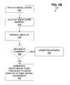
- step 240 integrates the images in a certain way. More specifically, the system 120 updates imagery presented by the display, namely the first image per step 236 , to integrate one or more of the other (not currently displayed) images into the display. More particularly, step 240 updates the displayed imagery to integrate a region of at least one of the secondary images into the display.
- Each integrated region has substantially identical represented coordinates as a counterpart region of the first image. For example, if the integrated region corresponds to Colorado, then the counterpart region of the first image is also Colorado. Stated in another way, the part of the second image that is being integrated into the display corresponds to a given part of the first image pursuant to the spatial coordinates. Moreover, each integrated region is presented in same scale and display location as the counterpart region of the first image.
- the integrated region of the second image (and counterpart region of the first image) may comprise the entire images or subparts of the respective images.
- step 240 may be carried out in various ways.
- the system 120 responds to the integrate gesture by performing a fade-out of the first image and a fade-in of one or more secondary images, as if the secondary images were initially hidden beneath the first image (in perfect alignment, and the same scale).
- the system 120 responds to the integrate gesture by opening a user defined, virtual window in the first image, through which the corresponding portion of one or more secondary images is viewed.
- FIG. 3A the system 120 responds to the integrate gesture by performing a fade-out of the first image and a fade-in of one or more secondary images, as if the secondary images were initially hidden beneath the first image (in perfect alignment, and the same scale).
- FIG. 4A the system 120 responds to the integrate gesture by opening a user defined, virtual window in the first image, through which the corresponding portion of one or more secondary images is viewed.
- FIG. 3A the system 120 responds to the integrate gesture by performing a fade-out of the first image and a fade-in of one or more secondary
- the system 120 responds to the integrate gesture by interpolating or “morphing” between the first image and one or more secondary images in proportion to user movement of a “slider” tool depicted on the display surface 124 .
- FIGS. 3A , 4 A, and 5 B are discussed in detail below.
- FIGS. 3A , 4 A, 5 A shows respective sequences 300 , 400 , 500 to illustrate various multi-layer embodiments.
- each sequence may be implemented as part of the gesture recognition and implementation sequence 200 , or vice versa, each sequence may also be implemented independent of the sequence 200 .
- each sequence 300 , 400 , 500 is described as a standalone product, although certain steps of each sequence may utilize operations similar to those of sequence 200 (such as steps 201 - 206 ).
- the aforementioned sequences are described in the hardware context of the interactive touch input system of FIGS. 1A-1C .
- the fade mode sequence 300 serves to “fade” from an initially displayed image to one or more initially images that are not initially displayed; this is performed in response to user touch applied to the display screen.
- the images are displayed in situ, so that each point on the display screen continues to show the same spatial coordinates regardless of which image is being shown.
- Steps 332 , 334 , 336 receive image layers, receive mapping, and present the first image in the same manner as steps 232 , 234 , 236 described above ( FIG. 2B ).
- an image-display mapping is developed between the first image and the display surface 124 to present the image with the desired scale.
- image-display mappings are well known components of computer graphics software and require no further description here, mention being made merely to aid in discussion of the fade window below.
- Step 338 detects whether the user has supplied a predetermined fade command.
- the fade command may be input by any type of user-to-computer input device or methodology, such as activating a predetermined selection of a GUI menu or other functional interface followed by manually contacting the display surface 124 .
- the fade command is detected whenever the user performs a predefined fade gesture comprising application of a predetermined threshold force to the display surface 124 with a sufficiently small velocity (e.g., less than a prescribed threshold velocity).
- various other processing 342 is performed, such as waiting for performance of a gesture, providing an error message to the user, or other operations such as those discussed above in context of steps 208 a , 209 , etc. of FIG. 2B .
- step 340 performs an act of integrating 340 the images. This involves defining a fade window ( 340 a ), fading-out the first image (step 340 b ), and fading-in a second image (step 340 c ).
- the fade window may be defined ( 340 a ) in various ways, with some examples of fade window including: (1) the entire display surface, (2) a predefined size and shape of window established by user selection or default settings, (3) a shape and size of window surrounding the point of user contact and proportional to the size, shape, and/or force of user contact with the display surface 124 , or (4) another arrangement entirely.
- steps 340 b - 340 c involve reducing visibility of the first image inside the fade window ( 340 b ), and increasing visibility of a second image within the fade window ( 340 c ).
- steps 340 b - 340 c reduce visibility of a region of the first image corresponding to the fade window, and increase visibility of the second image through the fade window as if the second image were residing beneath the first image (and aligned therewith according to the applicable mappings).
- one implementation is to utilize the image-display mapping to determine which spatial coordinates of the first image are bounded by the fade-window (such as by latitude/longitude), and then to use the mapping of step 334 to identify the same region in the second image.
- the identified region of the first image is subject to fade-out, and the identified region of the second image is subject to fade-in.
- steps 340 b - 340 c may be performed by the computer 126 reacting to user input by specifying appropriate transparency values of each image layer, and inputting them into an appropriate computer graphics program, mapping program, rendering program, or other such program for generating an output on the display 124 .
- each image is initially (e.g., step 336 ) assigned a transparency value indicative of the image's level of fade-in or fade-out.
- the first image has a transparency level of 0% and all other images have a transparency level of 100%.
- the system 120 displays each image according to its present transparency level.
- steps 340 b - 340 c are performed by simultaneously increasing the transparency value for the first image layer and decreasing the transparency level for the second image.
- the system 120 may operate to provide a rate of change in transparency that is proportional to the force applied (e.g., more force, more fade). Furthermore, the system 120 may automatically return to the presentation of the original image when the user force is removed or falls below a given threshold.
- steps 340 b - 340 c have the presentation effect of fading from the first image to the second image.
- fade-in and fade-out may be largely or precisely inversely proportional to provide a smooth transition. Fading may occur across the entire display surface, or within a limited window smaller than the display 124 .
- transition from one image to the next may be abrupt, or may involve gradually lessening the presentation of one image while gradually increasing the next in proportion to default settings, user-defined settings, size or force of user contact applied, etc.
- the system 100 may regulate the degree of fade in proportion to a parameter such as the amount of user force applied at the contact site.
- steps 340 b - 340 c involves a fade from first image to second, third, and further images that represent successive slices of the depicted subject matter in a particular order (such as higher layers to lower layers, etc.).
- the images may therefore compose a series of images having a defined order.
- the image layers' transparency is determined by the amount of user force applied to the display surface 124 .
- steps 340 b - 340 c may favor higher layers with lesser applied force, etc.
- transition between layers occurs smoothly, by interpolating between layers during transition between them; in a different embodiment, transition is abrupt, where only one layer has 100% transparency at a given time and all other layers have 0% transparency.
- step 344 the fade operation of step 340 is reversed.
- the fade is partially or completely reversed in response to lessening or removal of user contact with the display surface.
- fade may be reversed upon passage of a default or user-defined time, upon user performance of another prescribed gesture, user selection of a GUI menu entry, etc.
- step 340 involves increasing visibility of the first image in the virtual window, and reducing visibility of the second image in the window.
- FIG. 3B depicts an example of the foregoing fade operation.
- the user's hand 381 is applying force to an area 382 of the display surface 124 .
- the circular rings of 382 are shown to illustrate the contact between the user's hand 381 and the display surface, however, these rings are not visible in practice.
- the fade window in this example is the entire display surface 124 .
- the first image an aerial photograph
- a second image a roadmap of the same area
- the swipe mode sequence 400 presents a first image, and response to user definition of a swipe window on the display screen, presents a second image within the window instead of the first image.
- the second image is introduced in situ, so that each point on the display screen continues to show the same spatial coordinates, whether inside or outside the swipe window.
- the swipe window may be resizable in response to user input.
- steps 432 , 434 , 436 receive image layers, receive mapping, and present the first image in the same manner as steps 232 , 234 , 236 described above ( FIG. 2B ).
- steps 432 , 434 , 436 receive image layers, receive mapping, and present the first image in the same manner as steps 232 , 234 , 236 described above ( FIG. 2B ).
- an image-display mapping is developed between the first image and the display surface 124 to present the image with the desired scale.
- Particular layers may be designated to be displayed in swipe mode by a user selection through a configuration menu, by default, or by another technique.
- the system 120 may keep track of layer attributes in a lookup table or other file containing data about layers, such that when slider mode is selected (see below) the system only displays those layers designated for that mode. All other layers not so designated are not displayed in swipe mode.
- Step 438 recognizes when the user activates swipe mode. In one embodiment, this occurs by the user selecting swipe mode from a menu or other control interface. Alternatively, the system 120 may detect a predefined, user-applied swipe mode activation gesture distinguished by particular characteristics of touch position, velocity, and/or force.
- various other processing 442 is performed, such as waiting for performance of a this or a different gesture, providing an error message to the user, or other operations as discussed above in the context of steps 208 a , 209 , etc. of FIG. 2B .
- step 440 integrates the first image (initially displayed) and second image (not initially displayed) according to the swipe mode, as follows.
- the second image is that image layer designated by the operations discussed above.
- the system 120 defines a swipe area (step 440 a ). In discussing the swipe area, it is helpful to refer to vertical ( 469 ) and lateral ( 468 ) directions of the display 124 , as illustrated in FIG. 4B .
- the system 120 waits for occurrence of a first point of user contact on the display surface, then occurrence of a second point of contact away from said first location.
- the user may define the second point of contact in a different way—not by a new contact with the display 124 , but by dragging the first point of contact to a new location.
- Step 440 a defines the swipe area as a vertical band 467 of the display surface 124 laterally bounded by the vertical lines 460 - 461 passing through first (not shown) and second 466 contact points.
- the vertical band 467 swipe area
- the vertical band 467 has the lateral boundaries 460 - 461 , as defined by first (not shown) and second ( 466 ) contact points.
- the system 120 may update the display 124 to actually show the vertical lines 460 - 461 intersecting the respective contact points.
- display of these boundaries may be implied by the difference in appearance between the layers of imagery inside ( 462 ) and outside ( 465 ) the swipe area, as discussed below.
- the system 120 may recognize more than two borders to denote any desired rectangular area within the display, a circular area, a polygonal area, an irregular area designated by dragging a point of contact in a closed path on the display, etc.
- step 440 b after defining the swipe area 467 , the system 120 in step 440 b ceases display of the first image 465 within the swipe area 467 and instead displays the corresponding portion 462 of the second image. Consequently, from the user's perspective, the swipe area 467 has the effect of presenting a window through the first image into the second image's depiction of the same subject matter.
- Step 440 c maintains display of the first image outside the swipe area 467 .
- one implementation is to utilize the image-display mapping to determine which spatial coordinates of the first image are bounded by the swipe window (such as by latitude/longitude), and then to apply these spatial coordinates to identify the same region in the second image. Inside the swipe window, the first image is replaced by the identified region of the second image.
- the first image 465 (maintained outside the swipe area 467 ) is a satellite photo
- the second image 462 is a roadmap.
- steps 440 a - 440 c may be performed as follows.
- the second image is displayed and a screen shot is taken and stored, for example in bitmap format.
- the transparency of the second image is then set to 100% so that it disappears from view, quickly enough that this may be imperceptible to the user, and the first image is displayed (i.e. its transparency is set to 0%, or completely opaque).
- the screen shot is utilized as the second image in the swipe area. If the boundary 461 is subsequently redefined 440 a (discussed below), this is performed by varying a size of the earlier screen shot being presented.
- step 440 may optionally redefine the boundary 461 by repeating step 440 a , responsive to user touch and drag movements seeking to alter boundaries of the swipe area.
- the swipe area may be redefined (step 440 a ) whenever the user, after making the second point of contact, drags the contact point as illustrated by 464 .
- step 440 a may detect a new point of contact occurring at one of the lateral boundaries 460 - 461 (or within a given threshold of distance), and in response, step 440 a may modify the extent of the swipe area by moving that boundary responsive to initiating the new point of contact.
- step 440 a may also redefine contents of the area. For instance, step 440 may respond to user operation of a GUI menu or other functional interface to designate a different image for display in the swipe area. In this case, steps 440 b - 440 c are repeated in order to identify and thereafter present the relevant portion of the third, fourth, or other selected image in substitution of the image currently present in the swipe window.
- step 444 the swipe operation of step 440 may be discontinued.
- the system 120 removes the swipe area 467 and restores the first image 465 across the display surface 124 . This may be performed, for example, in response to removal of user contact with the display surface, or other events such as: passage of a default or user-defined time, user performance of another prescribed gesture, user selection of a menu entry, etc.
- the slider mode sequence 500 interpolates between different image layers according to position of a user-positioned slider tool.
- Each image is introduced in situ, so that each point on the display screen continues to show the same spatial coordinates, regardless of which image layer(s) are being shown.
- Steps 532 , 534 , 536 receive image layers, receive mapping, and present a first image in the same manner as steps 232 , 234 , 236 described above ( FIG. 2B ).
- an image-display mapping is developed between the first image and the display surface 124 to present the image with the desired scale.
- each image may represent (1) an image of certain subject matter as of a different time or date, (2) an image of a different floor plan of a multi-story building or ship, (3) an image of a different cross-sectional plan view of a multi-level circuit or machine, etc.
- Step 537 recognizes when the user has activated the slider mode. In one embodiment, this occurs when the user selects a slider mode from a menu or other control interface.
- the system 120 may detect a predefined slider mode activation gesture by analyzing touch position, velocity, and/or force.
- various other processing 542 is performed, such as waiting for performance of a this or a different gesture, providing an error message to the user, or other operations as discussed above in context of steps 208 a , 209 , etc. of FIG. 2B .
- the display 124 presents a slider tool in step 538 .
- the slider tool includes a bar, knob, button, dial, or other suitable GUI component.
- the presently described embodiment utilizes a linearly movable slider bar 560 illustrated in FIG. 5B .
- each designated linear position of the slider bar corresponds to a different image layer of step 532 .
- the slider bar is set up so that different positions of the slider bar correspond to different positions in the prescribed sequence of images.
- the slider bar observes an appropriately convenient scale.
- step 539 the system 120 analyzes user touch characteristics such as position, velocity, and/or force to determine whether the user has touched the slider bar, and dragged his/her finger (or stylus, or pen, etc.) in order to effectively push, pull, drag, or otherwise move the slider bar.
- user touch characteristics such as position, velocity, and/or force
- step 540 computes and displays the appropriate image. Whenever the slider bar occupies a position corresponding in the sequence to a single one of the images, step 540 presents that single image upon the display. For example, if there are ten images and ten slider positions, when the slider bar rests in position one, step 540 always presents image one.
- step 540 selects multiple images (each having a position in the given sequence with a predetermined relationship to slider tool position), and interpolates among the selected images. In one example, if the slider bar is between designated slider bar positions, step 540 selects the nearest two images to the slider bar position for interpolation. For example, if the slider bar rests between positions two and three, step 540 selects images two and three for interpolation. In one embodiment, a fixed weighting is always used (such as a 50% weighting of two images). In another embodiment, interpolation weighting is conducted in proportion to position of the slider bar.
- the degree of interpolation varies in proportion to the position of the slider bar between established slider bar positions. For example, if the slider bar is 30% of the way between positions five and six, and there is one image per position, then step 540 interpolates between images five and six with a 30% weighting to image six and a 70% weighting to image five.
- interpolation may be implemented by the computer 126 acting in response to user input to specify a transparency value for each image layer between 0% (fully opaque) and 100% (fully transparent), and inputting the image layers desired transparency values into a computer graphics or mapping program.
- step 540 may perform higher order interpolations.
- the interpolation formula may consider the contribution of layers adjacent to the slider button (as described previously) along with the contribution of one or more nonadjacent layers as well.
- the interpolation formula may consider non-adjacent layers only.
- the system 120 may ignore specified “hidden” layers in accordance with user-specified settings.
- the system 120 may keep track of layer attributes in a lookup table or other file containing data about layers, such that when slider mode is selected the system only displays those layers designated for use in slider mode.
- the “hidden” layers are ignored. This function may be implemented via menu, separate program, or other technique.
- all layers may be assumed hidden unless the user affirmatively specifies them as visible for use in the slider mode.
- step 540 ultimately displays the resultant image.
- the effect of step 540 is for the system 120 to “morph” between the image layers in response to slider bar position.
- the routine 500 returns to step 538 to determine whether the user has moved the slider bar, and if so, to re-interpolate images and present the resultant image as appropriate.
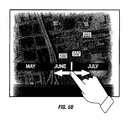
- One particular utility of the technique 500 is to graphically demonstrate changes in an aerial or other scene over time. In this embodiment, there are multiple images, appropriate in number to the desired level of detail and accuracy. In this embodiment, where the slider bar 560 is movable along a line, the slider bar is accompanied by a stationary time bar 562 indicating various image dates and/or times.
- the system 120 when the slider bar rests on a month for which an image is available, the system 120 presents the corresponding image 565 on the display 124 .
- the system 120 mathematically interpolates between the nearest available images in proportion to the placement of the slider bar 560 . For example, if the slider bar rests on June, and the nearest images correspond to May and July, then the system 120 interpolates between the May and July with a 50% weighting to each constituent image.
- the slider time bar represents the various layers with corresponding, evenly spaced, points along the length of the slider time bar.
- the system 120 recognizes leftward slider movements to present older imagery, and rightward slider bar movements to present newer imagery.
- the system 120 may act to simulate various physical properties, such as inertia and friction, to more closely approximate the look and feel of manipulating a physical object. Simulation of inertia, friction, and the like are discussed in greater detail above.
- the system 120 may simulate inertia to keep the slider in motion, blending between layers until the last layer is reached. Alternatively, once the last layer in the sequence is reached, the system 120 may perform a wraparound by resetting to the first image layer and continuing its motion. The system 120 may also simulate friction to slow the motion of the slider bar, once released. Responsive to a stop/slow command, such as touching the display, the system 120 halts or slows the motion.
- any illustrative logical blocks, modules, circuits, and process steps described herein may be implemented as electronic hardware, computer software, or combinations of both.
- various illustrative components, blocks, modules, circuits, and steps have been described above generally in terms of their functionality. Whether such functionality is implemented as hardware or software depends upon the particular application and design constraints imposed on the overall system. Skilled artisans may implement the described functionality in varying ways for each particular application, but such implementation decisions should not be interpreted as causing a departure from the scope of the present invention.
- DSP digital signal processor
- ASIC application specific integrated circuit
- FPGA field programmable gate array
- a general purpose processor may be a microprocessor, but in the alternative, the processor may be any conventional processor, controller, microcontroller, or state machine.
- a processor may also be implemented as a combination of computing devices, e.g., a combination of a DSP and a microprocessor, a plurality of microprocessors, one or more microprocessors in conjunction with a DSP core, or any other such configuration.
- a software module may reside in RAM memory, flash memory, ROM memory, EPROM memory, EEPROM memory, registers, hard disk, a removable disk, a CD-ROM, or any other form of storage medium known in the art.
- An exemplary storage medium is coupled to the processor such the processor can read information from, and write information to, the storage medium.
- the storage medium may be integral to the processor.
- the processor and the storage medium may reside in an ASIC.
Abstract
Description
Claims (17)
Priority Applications (1)
| Application Number | Priority Date | Filing Date | Title |
|---|---|---|---|
| US13/605,351 US8624863B2 (en) | 2004-08-06 | 2012-09-06 | Touch driven method and apparatus to integrate and display multiple image layers forming alternate depictions of same subject matter |
Applications Claiming Priority (6)
| Application Number | Priority Date | Filing Date | Title |
|---|---|---|---|
| US10/913,105 US7728821B2 (en) | 2004-08-06 | 2004-08-06 | Touch detecting interactive display |
| US70189205P | 2005-07-22 | 2005-07-22 | |
| US11/188,186 US7907124B2 (en) | 2004-08-06 | 2005-07-22 | Method and apparatus continuing action of user gestures performed upon a touch sensitive interactive display in simulation of inertia |
| US11/286,232 US7724242B2 (en) | 2004-08-06 | 2005-11-23 | Touch driven method and apparatus to integrate and display multiple image layers forming alternate depictions of same subject matter |
| US12/582,611 US8269739B2 (en) | 2004-08-06 | 2009-10-20 | Touch driven method and apparatus to integrate and display multiple image layers forming alternate depictions of same subject matter |
| US13/605,351 US8624863B2 (en) | 2004-08-06 | 2012-09-06 | Touch driven method and apparatus to integrate and display multiple image layers forming alternate depictions of same subject matter |
Related Parent Applications (1)
| Application Number | Title | Priority Date | Filing Date |
|---|---|---|---|
| US12/582,611 Continuation US8269739B2 (en) | 2004-08-06 | 2009-10-20 | Touch driven method and apparatus to integrate and display multiple image layers forming alternate depictions of same subject matter |
Publications (2)
| Publication Number | Publication Date |
|---|---|
| US20120331415A1 US20120331415A1 (en) | 2012-12-27 |
| US8624863B2 true US8624863B2 (en) | 2014-01-07 |
Family
ID=38067776
Family Applications (3)
| Application Number | Title | Priority Date | Filing Date |
|---|---|---|---|
| US11/286,232 Active 2027-12-07 US7724242B2 (en) | 2004-08-06 | 2005-11-23 | Touch driven method and apparatus to integrate and display multiple image layers forming alternate depictions of same subject matter |
| US12/582,611 Active 2025-09-29 US8269739B2 (en) | 2004-08-06 | 2009-10-20 | Touch driven method and apparatus to integrate and display multiple image layers forming alternate depictions of same subject matter |
| US13/605,351 Active US8624863B2 (en) | 2004-08-06 | 2012-09-06 | Touch driven method and apparatus to integrate and display multiple image layers forming alternate depictions of same subject matter |
Family Applications Before (2)
| Application Number | Title | Priority Date | Filing Date |
|---|---|---|---|
| US11/286,232 Active 2027-12-07 US7724242B2 (en) | 2004-08-06 | 2005-11-23 | Touch driven method and apparatus to integrate and display multiple image layers forming alternate depictions of same subject matter |
| US12/582,611 Active 2025-09-29 US8269739B2 (en) | 2004-08-06 | 2009-10-20 | Touch driven method and apparatus to integrate and display multiple image layers forming alternate depictions of same subject matter |
Country Status (5)
| Country | Link |
|---|---|
| US (3) | US7724242B2 (en) |
| EP (1) | EP1952221B1 (en) |
| ES (1) | ES2758710T3 (en) |
| HU (1) | HUE046090T2 (en) |
| WO (1) | WO2007061839A2 (en) |
Cited By (2)
| Publication number | Priority date | Publication date | Assignee | Title |
|---|---|---|---|---|
| US20130083072A1 (en) * | 2011-09-30 | 2013-04-04 | Casio Computer Co., Ltd. | Display apparatus, display control method, and storage medium storing program |
| US10073610B2 (en) | 2004-08-06 | 2018-09-11 | Qualcomm Incorporated | Bounding box gesture recognition on a touch detecting interactive display |
Families Citing this family (471)
| Publication number | Priority date | Publication date | Assignee | Title |
|---|---|---|---|---|
| GB9722766D0 (en) | 1997-10-28 | 1997-12-24 | British Telecomm | Portable computers |
| US7469381B2 (en) | 2007-01-07 | 2008-12-23 | Apple Inc. | List scrolling and document translation, scaling, and rotation on a touch-screen display |
| US8645137B2 (en) | 2000-03-16 | 2014-02-04 | Apple Inc. | Fast, language-independent method for user authentication by voice |
| US7492505B2 (en) * | 2001-08-17 | 2009-02-17 | Sipix Imaging, Inc. | Electrophoretic display with dual mode switching |
| US7397464B1 (en) * | 2004-04-30 | 2008-07-08 | Microsoft Corporation | Associating application states with a physical object |
| US7593593B2 (en) | 2004-06-16 | 2009-09-22 | Microsoft Corporation | Method and system for reducing effects of undesired signals in an infrared imaging system |
| US7724242B2 (en) | 2004-08-06 | 2010-05-25 | Touchtable, Inc. | Touch driven method and apparatus to integrate and display multiple image layers forming alternate depictions of same subject matter |
| US7728821B2 (en) | 2004-08-06 | 2010-06-01 | Touchtable, Inc. | Touch detecting interactive display |
| US7970870B2 (en) * | 2005-06-24 | 2011-06-28 | Microsoft Corporation | Extending digital artifacts through an interactive surface |
| US7911444B2 (en) | 2005-08-31 | 2011-03-22 | Microsoft Corporation | Input method for surface of interactive display |
| US8677377B2 (en) | 2005-09-08 | 2014-03-18 | Apple Inc. | Method and apparatus for building an intelligent automated assistant |
| US20090295830A1 (en) * | 2005-12-07 | 2009-12-03 | 3Dlabs Inc., Ltd. | User interface for inspection of photographs |
| US7509588B2 (en) | 2005-12-30 | 2009-03-24 | Apple Inc. | Portable electronic device with interface reconfiguration mode |
| US20070247422A1 (en) | 2006-03-30 | 2007-10-25 | Xuuk, Inc. | Interaction techniques for flexible displays |
| US20100045705A1 (en) * | 2006-03-30 | 2010-02-25 | Roel Vertegaal | Interaction techniques for flexible displays |
| US8111243B2 (en) | 2006-03-30 | 2012-02-07 | Cypress Semiconductor Corporation | Apparatus and method for recognizing a tap gesture on a touch sensing device |
| US9104270B2 (en) * | 2006-05-22 | 2015-08-11 | Thomson Licensing | Video system having a touch screen |
| JP2008017935A (en) | 2006-07-11 | 2008-01-31 | Aruze Corp | Game apparatus and its image change control method |
| US8589824B2 (en) * | 2006-07-13 | 2013-11-19 | Northrop Grumman Systems Corporation | Gesture recognition interface system |
| US8972902B2 (en) * | 2008-08-22 | 2015-03-03 | Northrop Grumman Systems Corporation | Compound gesture recognition |
| US9696808B2 (en) * | 2006-07-13 | 2017-07-04 | Northrop Grumman Systems Corporation | Hand-gesture recognition method |
| US8180114B2 (en) * | 2006-07-13 | 2012-05-15 | Northrop Grumman Systems Corporation | Gesture recognition interface system with vertical display |
| US7701439B2 (en) * | 2006-07-13 | 2010-04-20 | Northrop Grumman Corporation | Gesture recognition simulation system and method |
| US8234578B2 (en) * | 2006-07-25 | 2012-07-31 | Northrop Grumman Systems Corporatiom | Networked gesture collaboration system |
| US8432448B2 (en) * | 2006-08-10 | 2013-04-30 | Northrop Grumman Systems Corporation | Stereo camera intrusion detection system |
| US20080055257A1 (en) * | 2006-09-05 | 2008-03-06 | Juen-Tien Peng | Touch-Sensitive Interface Operating System |
| US8842074B2 (en) | 2006-09-06 | 2014-09-23 | Apple Inc. | Portable electronic device performing similar operations for different gestures |
| US7956849B2 (en) | 2006-09-06 | 2011-06-07 | Apple Inc. | Video manager for portable multifunction device |
| US8106856B2 (en) * | 2006-09-06 | 2012-01-31 | Apple Inc. | Portable electronic device for photo management |
| US10313505B2 (en) * | 2006-09-06 | 2019-06-04 | Apple Inc. | Portable multifunction device, method, and graphical user interface for configuring and displaying widgets |
| US7864163B2 (en) * | 2006-09-06 | 2011-01-04 | Apple Inc. | Portable electronic device, method, and graphical user interface for displaying structured electronic documents |
| US8564544B2 (en) | 2006-09-06 | 2013-10-22 | Apple Inc. | Touch screen device, method, and graphical user interface for customizing display of content category icons |
| US9304675B2 (en) | 2006-09-06 | 2016-04-05 | Apple Inc. | Portable electronic device for instant messaging |
| US9318108B2 (en) | 2010-01-18 | 2016-04-19 | Apple Inc. | Intelligent automated assistant |
| US8564543B2 (en) | 2006-09-11 | 2013-10-22 | Apple Inc. | Media player with imaged based browsing |
| US8736557B2 (en) * | 2006-09-11 | 2014-05-27 | Apple Inc. | Electronic device with image based browsers |
| US8214768B2 (en) * | 2007-01-05 | 2012-07-03 | Apple Inc. | Method, system, and graphical user interface for viewing multiple application windows |
| US7877707B2 (en) * | 2007-01-06 | 2011-01-25 | Apple Inc. | Detecting and interpreting real-world and security gestures on touch and hover sensitive devices |
| US8689132B2 (en) | 2007-01-07 | 2014-04-01 | Apple Inc. | Portable electronic device, method, and graphical user interface for displaying electronic documents and lists |
| US20080168402A1 (en) | 2007-01-07 | 2008-07-10 | Christopher Blumenberg | Application Programming Interfaces for Gesture Operations |
| US8519964B2 (en) | 2007-01-07 | 2013-08-27 | Apple Inc. | Portable multifunction device, method, and graphical user interface supporting user navigations of graphical objects on a touch screen display |
| US7844915B2 (en) * | 2007-01-07 | 2010-11-30 | Apple Inc. | Application programming interfaces for scrolling operations |
| US20080165148A1 (en) * | 2007-01-07 | 2008-07-10 | Richard Williamson | Portable Electronic Device, Method, and Graphical User Interface for Displaying Inline Multimedia Content |
| US9001047B2 (en) | 2007-01-07 | 2015-04-07 | Apple Inc. | Modal change based on orientation of a portable multifunction device |
| US20080168478A1 (en) * | 2007-01-07 | 2008-07-10 | Andrew Platzer | Application Programming Interfaces for Scrolling |
| US8212857B2 (en) * | 2007-01-26 | 2012-07-03 | Microsoft Corporation | Alternating light sources to reduce specular reflection |
| US8977255B2 (en) | 2007-04-03 | 2015-03-10 | Apple Inc. | Method and system for operating a multi-function portable electronic device using voice-activation |
| KR101420419B1 (en) | 2007-04-20 | 2014-07-30 | 엘지전자 주식회사 | Electronic Device And Method Of Editing Data Using the Same And Mobile Communication Terminal |
| US9772751B2 (en) | 2007-06-29 | 2017-09-26 | Apple Inc. | Using gestures to slide between user interfaces |
| US11126321B2 (en) * | 2007-09-04 | 2021-09-21 | Apple Inc. | Application menu user interface |
| US9619143B2 (en) | 2008-01-06 | 2017-04-11 | Apple Inc. | Device, method, and graphical user interface for viewing application launch icons |
| US8619038B2 (en) | 2007-09-04 | 2013-12-31 | Apple Inc. | Editing interface |
| AU2008299578B2 (en) * | 2007-09-11 | 2014-12-04 | Cruiser Interactive Pty Ltd | A system and method for capturing digital images |
| AU2008299579B2 (en) * | 2007-09-11 | 2014-03-27 | Cruiser Interactive Pty Ltd | A system and method for manipulating digital images on a computer display |
| JP5468005B2 (en) * | 2007-09-11 | 2014-04-09 | スマート・インターネット・テクノロジー・シーアールシー・プロプライエタリー・リミテッド | Interface elements for computer interfaces |
| WO2009033217A1 (en) * | 2007-09-11 | 2009-03-19 | Smart Internet Technology Crc Pty Ltd | Systems and methods for remote file transfer |
| US8583491B2 (en) * | 2007-09-19 | 2013-11-12 | T1visions, Inc. | Multimedia display, multimedia system including the display and associated methods |
| US8600816B2 (en) * | 2007-09-19 | 2013-12-03 | T1visions, Inc. | Multimedia, multiuser system and associated methods |
| US9953392B2 (en) | 2007-09-19 | 2018-04-24 | T1V, Inc. | Multimedia system and associated methods |
| US9965067B2 (en) | 2007-09-19 | 2018-05-08 | T1V, Inc. | Multimedia, multiuser system and associated methods |
| US20100179864A1 (en) | 2007-09-19 | 2010-07-15 | Feldman Michael R | Multimedia, multiuser system and associated methods |
| US8139110B2 (en) * | 2007-11-01 | 2012-03-20 | Northrop Grumman Systems Corporation | Calibration of a gesture recognition interface system |
| US9377874B2 (en) * | 2007-11-02 | 2016-06-28 | Northrop Grumman Systems Corporation | Gesture recognition light and video image projector |
| US20090125824A1 (en) * | 2007-11-12 | 2009-05-14 | Microsoft Corporation | User interface with physics engine for natural gestural control |
| US9171454B2 (en) | 2007-11-14 | 2015-10-27 | Microsoft Technology Licensing, Llc | Magic wand |
| US10002189B2 (en) | 2007-12-20 | 2018-06-19 | Apple Inc. | Method and apparatus for searching using an active ontology |
| US9330720B2 (en) | 2008-01-03 | 2016-05-03 | Apple Inc. | Methods and apparatus for altering audio output signals |
| US8327272B2 (en) | 2008-01-06 | 2012-12-04 | Apple Inc. | Portable multifunction device, method, and graphical user interface for viewing and managing electronic calendars |
| JP4877242B2 (en) * | 2008-02-06 | 2012-02-15 | ブラザー工業株式会社 | Image processing apparatus and image processing program |
| US20110202869A1 (en) * | 2008-02-28 | 2011-08-18 | Valups Corporation | Method for searching items |
| US8717305B2 (en) | 2008-03-04 | 2014-05-06 | Apple Inc. | Touch event model for web pages |
| US8174502B2 (en) | 2008-03-04 | 2012-05-08 | Apple Inc. | Touch event processing for web pages |
| US8645827B2 (en) | 2008-03-04 | 2014-02-04 | Apple Inc. | Touch event model |
| US8416196B2 (en) | 2008-03-04 | 2013-04-09 | Apple Inc. | Touch event model programming interface |
| JP4702388B2 (en) * | 2008-03-31 | 2011-06-15 | ブラザー工業株式会社 | Image processing apparatus and image processing program |
| US8996376B2 (en) | 2008-04-05 | 2015-03-31 | Apple Inc. | Intelligent text-to-speech conversion |
| DE102008017716A1 (en) * | 2008-04-07 | 2009-10-08 | Volkswagen Ag | Displaying and operating device for vehicle, has display device, touch-sensitive position detection unit coupled with display device, and controller which is coupled with display device and position detection unit |
| US8952894B2 (en) | 2008-05-12 | 2015-02-10 | Microsoft Technology Licensing, Llc | Computer vision-based multi-touch sensing using infrared lasers |
| US10496753B2 (en) | 2010-01-18 | 2019-12-03 | Apple Inc. | Automatically adapting user interfaces for hands-free interaction |
| AU2009250329A1 (en) * | 2008-05-19 | 2009-11-26 | Smart Internet Technology Crc Pty Ltd | Systems and methods for collaborative interaction |
| US8944608B2 (en) | 2008-06-17 | 2015-02-03 | The Invention Science Fund I, Llc | Systems and methods associated with projecting in response to conformation |
| US20110176119A1 (en) * | 2008-06-17 | 2011-07-21 | Searete Llc, A Limited Liability Corporation Of The State Of Delaware | Methods and systems for projecting in response to conformation |
| US20090309828A1 (en) * | 2008-06-17 | 2009-12-17 | Searete Llc, A Limited Liability Corporation Of The State Of Delaware | Methods and systems for transmitting instructions associated with user parameter responsive projection |
| US20090309826A1 (en) | 2008-06-17 | 2009-12-17 | Searete Llc, A Limited Liability Corporation Of The State Of Delaware | Systems and devices |
| US8936367B2 (en) | 2008-06-17 | 2015-01-20 | The Invention Science Fund I, Llc | Systems and methods associated with projecting in response to conformation |
| US8955984B2 (en) | 2008-06-17 | 2015-02-17 | The Invention Science Fund I, Llc | Projection associated methods and systems |
| US8345920B2 (en) * | 2008-06-20 | 2013-01-01 | Northrop Grumman Systems Corporation | Gesture recognition interface system with a light-diffusive screen |
| US8154524B2 (en) * | 2008-06-24 | 2012-04-10 | Microsoft Corporation | Physics simulation-based interaction for surface computing |
| JP4636131B2 (en) * | 2008-07-04 | 2011-02-23 | ソニー株式会社 | Information providing apparatus, information providing method, and program |
| US20100030549A1 (en) | 2008-07-31 | 2010-02-04 | Lee Michael M | Mobile device having human language translation capability with positional feedback |
| US20100031202A1 (en) * | 2008-08-04 | 2010-02-04 | Microsoft Corporation | User-defined gesture set for surface computing |
| US8847739B2 (en) * | 2008-08-04 | 2014-09-30 | Microsoft Corporation | Fusing RFID and vision for surface object tracking |
| EP2320311A4 (en) * | 2008-08-21 | 2013-11-06 | Konica Minolta Holdings Inc | Image display device |
| WO2010030984A1 (en) * | 2008-09-12 | 2010-03-18 | Gesturetek, Inc. | Orienting a displayed element relative to a user |
| CN102203850A (en) * | 2008-09-12 | 2011-09-28 | 格斯图尔泰克公司 | Orienting displayed elements relative to a user |
| US8676904B2 (en) | 2008-10-02 | 2014-03-18 | Apple Inc. | Electronic devices with voice command and contextual data processing capabilities |
| US8466879B2 (en) | 2008-10-26 | 2013-06-18 | Microsoft Corporation | Multi-touch manipulation of application objects |
| US8477103B2 (en) | 2008-10-26 | 2013-07-02 | Microsoft Corporation | Multi-touch object inertia simulation |
| WO2010049738A1 (en) * | 2008-10-30 | 2010-05-06 | The University Of Bristol | Representation system |
| US9477396B2 (en) * | 2008-11-25 | 2016-10-25 | Samsung Electronics Co., Ltd. | Device and method for providing a user interface |
| EP2196891A3 (en) * | 2008-11-25 | 2013-06-26 | Samsung Electronics Co., Ltd. | Device and method for providing a user interface |
| US20100153996A1 (en) * | 2008-12-17 | 2010-06-17 | Migos Charles J | Gesture based electronic program management system |
| US8030914B2 (en) * | 2008-12-29 | 2011-10-04 | Motorola Mobility, Inc. | Portable electronic device having self-calibrating proximity sensors |
| US8275412B2 (en) * | 2008-12-31 | 2012-09-25 | Motorola Mobility Llc | Portable electronic device having directional proximity sensors based on device orientation |
| US20100177051A1 (en) * | 2009-01-14 | 2010-07-15 | Microsoft Corporation | Touch display rubber-band gesture |
| US8633939B2 (en) * | 2009-02-05 | 2014-01-21 | Autodesk, Inc. | System and method for painting 3D models with 2D painting tools |
| US9141275B2 (en) * | 2009-02-17 | 2015-09-22 | Hewlett-Packard Development Company, L.P. | Rendering object icons associated with a first object icon upon detecting fingers moving apart |
| JP2010204730A (en) * | 2009-02-27 | 2010-09-16 | Seiko Epson Corp | System of controlling device in response to gesture |
| US8285499B2 (en) | 2009-03-16 | 2012-10-09 | Apple Inc. | Event recognition |
| US8689128B2 (en) | 2009-03-16 | 2014-04-01 | Apple Inc. | Device, method, and graphical user interface for moving a current position in content at a variable scrubbing rate |
| US9684521B2 (en) | 2010-01-26 | 2017-06-20 | Apple Inc. | Systems having discrete and continuous gesture recognizers |
| US8566044B2 (en) * | 2009-03-16 | 2013-10-22 | Apple Inc. | Event recognition |
| US8566045B2 (en) | 2009-03-16 | 2013-10-22 | Apple Inc. | Event recognition |
| US9311112B2 (en) | 2009-03-16 | 2016-04-12 | Apple Inc. | Event recognition |
| US20100271331A1 (en) * | 2009-04-22 | 2010-10-28 | Rachid Alameh | Touch-Screen and Method for an Electronic Device |
| US20100271312A1 (en) * | 2009-04-22 | 2010-10-28 | Rachid Alameh | Menu Configuration System and Method for Display on an Electronic Device |
| US8391719B2 (en) * | 2009-05-22 | 2013-03-05 | Motorola Mobility Llc | Method and system for conducting communication between mobile devices |
| US8269175B2 (en) * | 2009-05-22 | 2012-09-18 | Motorola Mobility Llc | Electronic device with sensing assembly and method for detecting gestures of geometric shapes |
| US8619029B2 (en) * | 2009-05-22 | 2013-12-31 | Motorola Mobility Llc | Electronic device with sensing assembly and method for interpreting consecutive gestures |
| US8294105B2 (en) * | 2009-05-22 | 2012-10-23 | Motorola Mobility Llc | Electronic device with sensing assembly and method for interpreting offset gestures |
| US8304733B2 (en) * | 2009-05-22 | 2012-11-06 | Motorola Mobility Llc | Sensing assembly for mobile device |
| US8788676B2 (en) * | 2009-05-22 | 2014-07-22 | Motorola Mobility Llc | Method and system for controlling data transmission to or from a mobile device |
| US8344325B2 (en) * | 2009-05-22 | 2013-01-01 | Motorola Mobility Llc | Electronic device with sensing assembly and method for detecting basic gestures |
| US8542186B2 (en) * | 2009-05-22 | 2013-09-24 | Motorola Mobility Llc | Mobile device with user interaction capability and method of operating same |
| US10241644B2 (en) | 2011-06-03 | 2019-03-26 | Apple Inc. | Actionable reminder entries |
| US10241752B2 (en) | 2011-09-30 | 2019-03-26 | Apple Inc. | Interface for a virtual digital assistant |
| US9858925B2 (en) | 2009-06-05 | 2018-01-02 | Apple Inc. | Using context information to facilitate processing of commands in a virtual assistant |
| US10255566B2 (en) | 2011-06-03 | 2019-04-09 | Apple Inc. | Generating and processing task items that represent tasks to perform |
| US9431006B2 (en) | 2009-07-02 | 2016-08-30 | Apple Inc. | Methods and apparatuses for automatic speech recognition |
| US8319170B2 (en) * | 2009-07-10 | 2012-11-27 | Motorola Mobility Llc | Method for adapting a pulse power mode of a proximity sensor |
| US8667423B2 (en) * | 2009-08-04 | 2014-03-04 | Hewlett-Packard Development Company, L.P. | Multi-touch wallpaper management |
| US20110043461A1 (en) * | 2009-08-24 | 2011-02-24 | Ming-Te Lai | Systems and methods for application management |
| JP2011048685A (en) * | 2009-08-27 | 2011-03-10 | Kyocera Corp | Input apparatus |
| JP5593655B2 (en) * | 2009-08-31 | 2014-09-24 | ソニー株式会社 | Information processing apparatus, information processing method, and program |
| KR101631273B1 (en) * | 2009-10-26 | 2016-06-17 | 삼성전자주식회사 | Method and apparatus for providing UI animation |
| US8665227B2 (en) * | 2009-11-19 | 2014-03-04 | Motorola Mobility Llc | Method and apparatus for replicating physical key function with soft keys in an electronic device |
| TWI412978B (en) * | 2009-12-23 | 2013-10-21 | Hon Hai Prec Ind Co Ltd | Electronic device with infrared touch-control function and method thereof |
| US20110157051A1 (en) * | 2009-12-25 | 2011-06-30 | Sanyo Electric Co., Ltd. | Multilayer display device |
| US20110161892A1 (en) * | 2009-12-29 | 2011-06-30 | Motorola-Mobility, Inc. | Display Interface and Method for Presenting Visual Feedback of a User Interaction |
| US8438504B2 (en) | 2010-01-06 | 2013-05-07 | Apple Inc. | Device, method, and graphical user interface for navigating through multiple viewing areas |
| US20110167350A1 (en) * | 2010-01-06 | 2011-07-07 | Apple Inc. | Assist Features For Content Display Device |
| US8736561B2 (en) | 2010-01-06 | 2014-05-27 | Apple Inc. | Device, method, and graphical user interface with content display modes and display rotation heuristics |
| US10276170B2 (en) | 2010-01-18 | 2019-04-30 | Apple Inc. | Intelligent automated assistant |
| US10679605B2 (en) | 2010-01-18 | 2020-06-09 | Apple Inc. | Hands-free list-reading by intelligent automated assistant |
| US10553209B2 (en) | 2010-01-18 | 2020-02-04 | Apple Inc. | Systems and methods for hands-free notification summaries |
| US10705794B2 (en) | 2010-01-18 | 2020-07-07 | Apple Inc. | Automatically adapting user interfaces for hands-free interaction |
| US10007393B2 (en) * | 2010-01-19 | 2018-06-26 | Apple Inc. | 3D view of file structure |
| US8977584B2 (en) | 2010-01-25 | 2015-03-10 | Newvaluexchange Global Ai Llp | Apparatuses, methods and systems for a digital conversation management platform |
| EP2357220A1 (en) * | 2010-02-10 | 2011-08-17 | The Procter & Gamble Company | Cleaning composition comprising amylase variants with high stability in the presence of a chelating agent |
| US9417787B2 (en) * | 2010-02-12 | 2016-08-16 | Microsoft Technology Licensing, Llc | Distortion effects to indicate location in a movable data collection |
| US8473860B2 (en) * | 2010-02-12 | 2013-06-25 | Microsoft Corporation | Multi-layer user interface with flexible parallel and orthogonal movement |
| US20110199318A1 (en) * | 2010-02-12 | 2011-08-18 | Microsoft Corporation | Multi-layer user interface with flexible parallel movement |
| US8682667B2 (en) | 2010-02-25 | 2014-03-25 | Apple Inc. | User profiling for selecting user specific voice input processing information |
| DE102011006344B4 (en) | 2010-03-31 | 2020-03-12 | Joyson Safety Systems Acquisition Llc | Occupant measurement system |
| JP5805974B2 (en) | 2010-03-31 | 2015-11-10 | ティーケー ホールディングス,インコーポレーテッド | Steering wheel sensor |
| DE102011006649B4 (en) | 2010-04-02 | 2018-05-03 | Tk Holdings Inc. | Steering wheel with hand sensors |
| US8423911B2 (en) | 2010-04-07 | 2013-04-16 | Apple Inc. | Device, method, and graphical user interface for managing folders |
| US10788976B2 (en) | 2010-04-07 | 2020-09-29 | Apple Inc. | Device, method, and graphical user interface for managing folders with multiple pages |
| US8963845B2 (en) | 2010-05-05 | 2015-02-24 | Google Technology Holdings LLC | Mobile device with temperature sensing capability and method of operating same |
| US9728868B1 (en) | 2010-05-05 | 2017-08-08 | Cree Fayetteville, Inc. | Apparatus having self healing liquid phase power connects and method thereof |
| JP5440374B2 (en) * | 2010-05-14 | 2014-03-12 | 富士ゼロックス株式会社 | Information processing apparatus and program |
| US8751056B2 (en) | 2010-05-25 | 2014-06-10 | Motorola Mobility Llc | User computer device with temperature sensing capabilities and method of operating same |
| US9103732B2 (en) | 2010-05-25 | 2015-08-11 | Google Technology Holdings LLC | User computer device with temperature sensing capabilities and method of operating same |
| US8335991B2 (en) * | 2010-06-11 | 2012-12-18 | Microsoft Corporation | Secure application interoperation via user interface gestures |
| US8552999B2 (en) | 2010-06-14 | 2013-10-08 | Apple Inc. | Control selection approximation |
| US20120011465A1 (en) * | 2010-07-06 | 2012-01-12 | Marcelo Amaral Rezende | Digital whiteboard system |
| KR20120020010A (en) * | 2010-08-27 | 2012-03-07 | 삼성전자주식회사 | Method and apparatus for displaying contents |
| KR101739054B1 (en) | 2010-09-08 | 2017-05-24 | 삼성전자주식회사 | Motion control method and apparatus in a device |
| US9164670B2 (en) * | 2010-09-15 | 2015-10-20 | Microsoft Technology Licensing, Llc | Flexible touch-based scrolling |
| US9021402B1 (en) | 2010-09-24 | 2015-04-28 | Google Inc. | Operation of mobile device interface using gestures |
| US8860766B2 (en) * | 2010-09-30 | 2014-10-14 | Nvidia Corporation | System, method, and computer program product for determining one or more contact points between a pair of objects |
| US9652201B2 (en) * | 2010-10-01 | 2017-05-16 | Adobe Systems Incorporated | Methods and systems for physically-based runtime effects |
| US8667425B1 (en) | 2010-10-05 | 2014-03-04 | Google Inc. | Touch-sensitive device scratch card user interface |
| US9244606B2 (en) | 2010-12-20 | 2016-01-26 | Apple Inc. | Device, method, and graphical user interface for navigation of concurrently open software applications |
| US9201185B2 (en) | 2011-02-04 | 2015-12-01 | Microsoft Technology Licensing, Llc | Directional backlighting for display panels |
| US20120216152A1 (en) * | 2011-02-23 | 2012-08-23 | Google Inc. | Touch gestures for remote control operations |
| US9262612B2 (en) | 2011-03-21 | 2016-02-16 | Apple Inc. | Device access using voice authentication |
| US9298363B2 (en) | 2011-04-11 | 2016-03-29 | Apple Inc. | Region activation for touch sensitive surface |
| US8863039B2 (en) | 2011-04-18 | 2014-10-14 | Microsoft Corporation | Multi-dimensional boundary effects |
| US20120272144A1 (en) * | 2011-04-20 | 2012-10-25 | Microsoft Corporation | Compact control menu for touch-enabled command execution |
| US8612808B2 (en) * | 2011-05-05 | 2013-12-17 | International Business Machines Corporation | Touch-sensitive user input device failure prediction |
| JP2012248067A (en) * | 2011-05-30 | 2012-12-13 | Canon Inc | Information input device, control method for the same and control program |
| US10057736B2 (en) | 2011-06-03 | 2018-08-21 | Apple Inc. | Active transport based notifications |
| FR2976681B1 (en) * | 2011-06-17 | 2013-07-12 | Inst Nat Rech Inf Automat | SYSTEM FOR COLOCATING A TOUCH SCREEN AND A VIRTUAL OBJECT AND DEVICE FOR HANDLING VIRTUAL OBJECTS USING SUCH A SYSTEM |
| US8775966B2 (en) * | 2011-06-29 | 2014-07-08 | Motorola Mobility Llc | Electronic device and method with dual mode rear TouchPad |
| US9417754B2 (en) | 2011-08-05 | 2016-08-16 | P4tents1, LLC | User interface system, method, and computer program product |
| KR20130017241A (en) * | 2011-08-10 | 2013-02-20 | 삼성전자주식회사 | Method and apparauts for input and output in touch screen terminal |
| US8994660B2 (en) | 2011-08-29 | 2015-03-31 | Apple Inc. | Text correction processing |
| US9063591B2 (en) | 2011-11-30 | 2015-06-23 | Google Technology Holdings LLC | Active styluses for interacting with a mobile device |
| US8963885B2 (en) | 2011-11-30 | 2015-02-24 | Google Technology Holdings LLC | Mobile device for interacting with an active stylus |
| DE112012005665B4 (en) | 2012-01-12 | 2022-11-03 | Mitsubishi Electric Corporation | Map display device and map display method |
| WO2013105249A1 (en) * | 2012-01-12 | 2013-07-18 | 三菱電機株式会社 | Map display device and map display method |
| US9761205B2 (en) * | 2012-01-12 | 2017-09-12 | Mistubishi Electric Corporation | Map display device and map display method |
| US9052414B2 (en) | 2012-02-07 | 2015-06-09 | Microsoft Technology Licensing, Llc | Virtual image device |
| US9354748B2 (en) | 2012-02-13 | 2016-05-31 | Microsoft Technology Licensing, Llc | Optical stylus interaction |
| US9213479B2 (en) * | 2012-02-16 | 2015-12-15 | Samsung Medison Co., Ltd. | Method and apparatus for displaying image |
| US9672796B2 (en) * | 2012-02-17 | 2017-06-06 | Lg Electronics Inc. | Electronic device including flexible display |
| US8749529B2 (en) | 2012-03-01 | 2014-06-10 | Microsoft Corporation | Sensor-in-pixel display system with near infrared filter |
| US9064654B2 (en) | 2012-03-02 | 2015-06-23 | Microsoft Technology Licensing, Llc | Method of manufacturing an input device |
| US9460029B2 (en) | 2012-03-02 | 2016-10-04 | Microsoft Technology Licensing, Llc | Pressure sensitive keys |
| USRE48963E1 (en) | 2012-03-02 | 2022-03-08 | Microsoft Technology Licensing, Llc | Connection device for computing devices |
| US9075566B2 (en) | 2012-03-02 | 2015-07-07 | Microsoft Technoogy Licensing, LLC | Flexible hinge spine |
| US10134385B2 (en) | 2012-03-02 | 2018-11-20 | Apple Inc. | Systems and methods for name pronunciation |
| US9426905B2 (en) | 2012-03-02 | 2016-08-23 | Microsoft Technology Licensing, Llc | Connection device for computing devices |
| US9360893B2 (en) | 2012-03-02 | 2016-06-07 | Microsoft Technology Licensing, Llc | Input device writing surface |
| US9298236B2 (en) | 2012-03-02 | 2016-03-29 | Microsoft Technology Licensing, Llc | Multi-stage power adapter configured to provide a first power level upon initial connection of the power adapter to the host device and a second power level thereafter upon notification from the host device to the power adapter |
| US9870066B2 (en) | 2012-03-02 | 2018-01-16 | Microsoft Technology Licensing, Llc | Method of manufacturing an input device |
| US8873227B2 (en) | 2012-03-02 | 2014-10-28 | Microsoft Corporation | Flexible hinge support layer |
| US9483461B2 (en) | 2012-03-06 | 2016-11-01 | Apple Inc. | Handling speech synthesis of content for multiple languages |
| GB201204336D0 (en) * | 2012-03-12 | 2012-04-25 | Stepsahead Ltd | Projection system |
| CN102662576B (en) * | 2012-03-29 | 2015-04-29 | 华为终端有限公司 | Method and device for sending out information based on touch |
| WO2013154720A1 (en) | 2012-04-13 | 2013-10-17 | Tk Holdings Inc. | Pressure sensor including a pressure sensitive material for use with control systems and methods of using the same |
| DE102012103887B4 (en) * | 2012-05-03 | 2018-12-13 | Thomas Reitmeier | Arrangement of a table and a picture projecting device as well as use and control method |
| CN104487929B (en) | 2012-05-09 | 2018-08-17 | 苹果公司 | For contacting the equipment for carrying out display additional information, method and graphic user interface in response to user |
| WO2013169845A1 (en) | 2012-05-09 | 2013-11-14 | Yknots Industries Llc | Device, method, and graphical user interface for scrolling nested regions |
| EP2847662B1 (en) | 2012-05-09 | 2020-02-19 | Apple Inc. | Device, method, and graphical user interface for providing feedback for changing activation states of a user interface object |
| EP3185116B1 (en) | 2012-05-09 | 2019-09-11 | Apple Inc. | Device, method and graphical user interface for providing tactile feedback for operations performed in a user interface |
| WO2013169851A2 (en) | 2012-05-09 | 2013-11-14 | Yknots Industries Llc | Device, method, and graphical user interface for facilitating user interaction with controls in a user interface |
| KR101670570B1 (en) | 2012-05-09 | 2016-10-28 | 애플 인크. | Device, method, and graphical user interface for selecting user interface objects |
| JP2015519656A (en) | 2012-05-09 | 2015-07-09 | アップル インコーポレイテッド | Device, method and graphical user interface for moving and dropping user interface objects |
| WO2013169842A2 (en) | 2012-05-09 | 2013-11-14 | Yknots Industries Llc | Device, method, and graphical user interface for selecting object within a group of objects |
| WO2013169875A2 (en) | 2012-05-09 | 2013-11-14 | Yknots Industries Llc | Device, method, and graphical user interface for displaying content associated with a corresponding affordance |
| WO2013169849A2 (en) | 2012-05-09 | 2013-11-14 | Industries Llc Yknots | Device, method, and graphical user interface for displaying user interface objects corresponding to an application |
| WO2013169865A2 (en) | 2012-05-09 | 2013-11-14 | Yknots Industries Llc | Device, method, and graphical user interface for moving a user interface object based on an intensity of a press input |
| WO2013169843A1 (en) | 2012-05-09 | 2013-11-14 | Yknots Industries Llc | Device, method, and graphical user interface for manipulating framed graphical objects |
| WO2013169870A1 (en) | 2012-05-09 | 2013-11-14 | Yknots Industries Llc | Device, method, and graphical user interface for transitioning between display states in response to gesture |
| US9280610B2 (en) | 2012-05-14 | 2016-03-08 | Apple Inc. | Crowd sourcing information to fulfill user requests |
| US20130300590A1 (en) | 2012-05-14 | 2013-11-14 | Paul Henry Dietz | Audio Feedback |
| US10417037B2 (en) | 2012-05-15 | 2019-09-17 | Apple Inc. | Systems and methods for integrating third party services with a digital assistant |
| US9721563B2 (en) | 2012-06-08 | 2017-08-01 | Apple Inc. | Name recognition system |
| US10031556B2 (en) | 2012-06-08 | 2018-07-24 | Microsoft Technology Licensing, Llc | User experience adaptation |
| US8947353B2 (en) | 2012-06-12 | 2015-02-03 | Microsoft Corporation | Photosensor array gesture detection |
| US9019615B2 (en) | 2012-06-12 | 2015-04-28 | Microsoft Technology Licensing, Llc | Wide field-of-view virtual image projector |
| US9459160B2 (en) | 2012-06-13 | 2016-10-04 | Microsoft Technology Licensing, Llc | Input device sensor configuration |
| US9073123B2 (en) | 2012-06-13 | 2015-07-07 | Microsoft Technology Licensing, Llc | Housing vents |
| US9684382B2 (en) | 2012-06-13 | 2017-06-20 | Microsoft Technology Licensing, Llc | Input device configuration having capacitive and pressure sensors |
| US9256089B2 (en) | 2012-06-15 | 2016-02-09 | Microsoft Technology Licensing, Llc | Object-detecting backlight unit |
| US9495129B2 (en) | 2012-06-29 | 2016-11-15 | Apple Inc. | Device, method, and user interface for voice-activated navigation and browsing of a document |
| US9098516B2 (en) * | 2012-07-18 | 2015-08-04 | DS Zodiac, Inc. | Multi-dimensional file system |
| US9355345B2 (en) | 2012-07-23 | 2016-05-31 | Microsoft Technology Licensing, Llc | Transparent tags with encoded data |
| EP2696269A1 (en) * | 2012-08-10 | 2014-02-12 | BlackBerry Limited | Method of momentum based zoom of content on an electronic device |
| US8964379B2 (en) | 2012-08-20 | 2015-02-24 | Microsoft Corporation | Switchable magnetic lock |
| US20140059496A1 (en) * | 2012-08-23 | 2014-02-27 | Oracle International Corporation | Unified mobile approvals application including card display |
| US9696223B2 (en) | 2012-09-17 | 2017-07-04 | Tk Holdings Inc. | Single layer force sensor |
| US9547647B2 (en) | 2012-09-19 | 2017-01-17 | Apple Inc. | Voice-based media searching |
| US9152173B2 (en) | 2012-10-09 | 2015-10-06 | Microsoft Technology Licensing, Llc | Transparent display device |
| US9513792B2 (en) * | 2012-10-10 | 2016-12-06 | Sap Se | Input gesture chart scaling |
| US8654030B1 (en) | 2012-10-16 | 2014-02-18 | Microsoft Corporation | Antenna placement |
| EP2908970B1 (en) | 2012-10-17 | 2018-01-03 | Microsoft Technology Licensing, LLC | Metal alloy injection molding protrusions |
| WO2014059618A1 (en) | 2012-10-17 | 2014-04-24 | Microsoft Corporation | Graphic formation via material ablation |
| US9589538B2 (en) * | 2012-10-17 | 2017-03-07 | Perceptive Pixel, Inc. | Controlling virtual objects |
| WO2014059625A1 (en) | 2012-10-17 | 2014-04-24 | Microsoft Corporation | Metal alloy injection molding overflows |
| US9275282B2 (en) | 2012-10-30 | 2016-03-01 | Qualcomm Incorporated | Processing and managing multiple maps for an LCI |
| US8952892B2 (en) | 2012-11-01 | 2015-02-10 | Microsoft Corporation | Input location correction tables for input panels |
| US8786767B2 (en) | 2012-11-02 | 2014-07-22 | Microsoft Corporation | Rapid synchronized lighting and shuttering |
| EP2917810A4 (en) | 2012-11-06 | 2016-06-22 | Hewlett Packard Development Co | Interactive display |
| US9513748B2 (en) | 2012-12-13 | 2016-12-06 | Microsoft Technology Licensing, Llc | Combined display panel circuit |
| CN105264479B (en) | 2012-12-29 | 2018-12-25 | 苹果公司 | Equipment, method and graphic user interface for navigating to user interface hierarchical structure |
| EP3564806B1 (en) | 2012-12-29 | 2024-02-21 | Apple Inc. | Device, method and graphical user interface for determining whether to scroll or select contents |
| KR101958517B1 (en) | 2012-12-29 | 2019-03-14 | 애플 인크. | Device, method, and graphical user interface for transitioning between touch input to display output relationships |
| EP2939095B1 (en) | 2012-12-29 | 2018-10-03 | Apple Inc. | Device, method, and graphical user interface for moving a cursor according to a change in an appearance of a control icon with simulated three-dimensional characteristics |
| WO2014105279A1 (en) | 2012-12-29 | 2014-07-03 | Yknots Industries Llc | Device, method, and graphical user interface for switching between user interfaces |
| EP2912542B1 (en) | 2012-12-29 | 2022-07-13 | Apple Inc. | Device and method for forgoing generation of tactile output for a multi-contact gesture |
| GB2509517B (en) * | 2013-01-04 | 2021-03-10 | Vertegaal Roel | Computing apparatus |
| JP5489379B1 (en) * | 2013-01-18 | 2014-05-14 | パナソニック株式会社 | Scroll device, scroll method and program |
| US9146668B2 (en) * | 2013-01-31 | 2015-09-29 | Hewlett-Packard Development Company, L.P. | Graphical element placement on a display surface |
| US9176538B2 (en) | 2013-02-05 | 2015-11-03 | Microsoft Technology Licensing, Llc | Input device configurations |
| EP2954514B1 (en) | 2013-02-07 | 2021-03-31 | Apple Inc. | Voice trigger for a digital assistant |
| US10578499B2 (en) | 2013-02-17 | 2020-03-03 | Microsoft Technology Licensing, Llc | Piezo-actuated virtual buttons for touch surfaces |
| US9638835B2 (en) | 2013-03-05 | 2017-05-02 | Microsoft Technology Licensing, Llc | Asymmetric aberration correcting lens |
| US10652394B2 (en) | 2013-03-14 | 2020-05-12 | Apple Inc. | System and method for processing voicemail |
| US10748529B1 (en) | 2013-03-15 | 2020-08-18 | Apple Inc. | Voice activated device for use with a voice-based digital assistant |
| US9304549B2 (en) | 2013-03-28 | 2016-04-05 | Microsoft Technology Licensing, Llc | Hinge mechanism for rotatable component attachment |
| US9552777B2 (en) | 2013-05-10 | 2017-01-24 | Microsoft Technology Licensing, Llc | Phase control backlight |
| US20140359539A1 (en) * | 2013-05-31 | 2014-12-04 | Lenovo (Singapore) Pte, Ltd. | Organizing display data on a multiuser display |
| US9582608B2 (en) | 2013-06-07 | 2017-02-28 | Apple Inc. | Unified ranking with entropy-weighted information for phrase-based semantic auto-completion |
| WO2014197336A1 (en) | 2013-06-07 | 2014-12-11 | Apple Inc. | System and method for detecting errors in interactions with a voice-based digital assistant |
| WO2014197334A2 (en) | 2013-06-07 | 2014-12-11 | Apple Inc. | System and method for user-specified pronunciation of words for speech synthesis and recognition |
| WO2014197335A1 (en) | 2013-06-08 | 2014-12-11 | Apple Inc. | Interpreting and acting upon commands that involve sharing information with remote devices |
| US9733716B2 (en) | 2013-06-09 | 2017-08-15 | Apple Inc. | Proxy gesture recognizer |
| WO2014200728A1 (en) | 2013-06-09 | 2014-12-18 | Apple Inc. | Device, method, and graphical user interface for enabling conversation persistence across two or more instances of a digital assistant |
| US10176167B2 (en) | 2013-06-09 | 2019-01-08 | Apple Inc. | System and method for inferring user intent from speech inputs |
| EP2816458A1 (en) * | 2013-06-18 | 2014-12-24 | Thomson Licensing | Method and apparatus for controlling example-based image manipulation |
| US9128552B2 (en) | 2013-07-17 | 2015-09-08 | Lenovo (Singapore) Pte. Ltd. | Organizing display data on a multiuser display |
| KR20150019061A (en) * | 2013-08-12 | 2015-02-25 | 삼성전자주식회사 | Method for wireless pairing and electronic device thereof |
| US9223340B2 (en) | 2013-08-14 | 2015-12-29 | Lenovo (Singapore) Pte. Ltd. | Organizing display data on a multiuser display |
| EP3058448A4 (en) * | 2013-10-18 | 2017-04-12 | Citrix Systems Inc. | Providing enhanced message management user interfaces |
| EP3063608B1 (en) | 2013-10-30 | 2020-02-12 | Apple Inc. | Displaying relevant user interface objects |
| US10296160B2 (en) | 2013-12-06 | 2019-05-21 | Apple Inc. | Method for extracting salient dialog usage from live data |
| US9448631B2 (en) | 2013-12-31 | 2016-09-20 | Microsoft Technology Licensing, Llc | Input device haptics and pressure sensing |
| US9317072B2 (en) | 2014-01-28 | 2016-04-19 | Microsoft Technology Licensing, Llc | Hinge mechanism with preset positions |
| US9759854B2 (en) | 2014-02-17 | 2017-09-12 | Microsoft Technology Licensing, Llc | Input device outer layer and backlighting |
| US20150268838A1 (en) * | 2014-03-20 | 2015-09-24 | Institute For Information Industry | Methods, systems, electronic devices, and non-transitory computer readable storage medium media for behavior based user interface layout display (build) |
| US10120420B2 (en) | 2014-03-21 | 2018-11-06 | Microsoft Technology Licensing, Llc | Lockable display and techniques enabling use of lockable displays |
| US9633004B2 (en) | 2014-05-30 | 2017-04-25 | Apple Inc. | Better resolution when referencing to concepts |
| US9715875B2 (en) | 2014-05-30 | 2017-07-25 | Apple Inc. | Reducing the need for manual start/end-pointing and trigger phrases |
| US9785630B2 (en) | 2014-05-30 | 2017-10-10 | Apple Inc. | Text prediction using combined word N-gram and unigram language models |
| US11256294B2 (en) | 2014-05-30 | 2022-02-22 | Apple Inc. | Continuity of applications across devices |
| US9842101B2 (en) | 2014-05-30 | 2017-12-12 | Apple Inc. | Predictive conversion of language input |
| US10170123B2 (en) | 2014-05-30 | 2019-01-01 | Apple Inc. | Intelligent assistant for home automation |
| US9760559B2 (en) | 2014-05-30 | 2017-09-12 | Apple Inc. | Predictive text input |
| US9966065B2 (en) | 2014-05-30 | 2018-05-08 | Apple Inc. | Multi-command single utterance input method |
| US9430463B2 (en) | 2014-05-30 | 2016-08-30 | Apple Inc. | Exemplar-based natural language processing |
| US10078631B2 (en) | 2014-05-30 | 2018-09-18 | Apple Inc. | Entropy-guided text prediction using combined word and character n-gram language models |
| US10659851B2 (en) | 2014-06-30 | 2020-05-19 | Apple Inc. | Real-time digital assistant knowledge updates |
| US9338493B2 (en) | 2014-06-30 | 2016-05-10 | Apple Inc. | Intelligent automated assistant for TV user interactions |
| US10324733B2 (en) | 2014-07-30 | 2019-06-18 | Microsoft Technology Licensing, Llc | Shutdown notifications |
| CN106796446B (en) * | 2014-08-04 | 2020-05-12 | 惠普发展公司,有限责任合伙企业 | Workspace metadata management |
| US10446141B2 (en) | 2014-08-28 | 2019-10-15 | Apple Inc. | Automatic speech recognition based on user feedback |
| CN106797493A (en) | 2014-09-02 | 2017-05-31 | 苹果公司 | Music user interface |
| US9818400B2 (en) | 2014-09-11 | 2017-11-14 | Apple Inc. | Method and apparatus for discovering trending terms in speech requests |
| US10789041B2 (en) | 2014-09-12 | 2020-09-29 | Apple Inc. | Dynamic thresholds for always listening speech trigger |
| US9424048B2 (en) | 2014-09-15 | 2016-08-23 | Microsoft Technology Licensing, Llc | Inductive peripheral retention device |
| US10074360B2 (en) | 2014-09-30 | 2018-09-11 | Apple Inc. | Providing an indication of the suitability of speech recognition |
| US9447620B2 (en) | 2014-09-30 | 2016-09-20 | Microsoft Technology Licensing, Llc | Hinge mechanism with multiple preset positions |
| US10127911B2 (en) | 2014-09-30 | 2018-11-13 | Apple Inc. | Speaker identification and unsupervised speaker adaptation techniques |
| US9646609B2 (en) | 2014-09-30 | 2017-05-09 | Apple Inc. | Caching apparatus for serving phonetic pronunciations |
| US9886432B2 (en) | 2014-09-30 | 2018-02-06 | Apple Inc. | Parsimonious handling of word inflection via categorical stem + suffix N-gram language models |
| US9668121B2 (en) | 2014-09-30 | 2017-05-30 | Apple Inc. | Social reminders |
| US10552013B2 (en) | 2014-12-02 | 2020-02-04 | Apple Inc. | Data detection |
| US20160202865A1 (en) | 2015-01-08 | 2016-07-14 | Apple Inc. | Coordination of static backgrounds and rubberbanding |
| US9865280B2 (en) | 2015-03-06 | 2018-01-09 | Apple Inc. | Structured dictation using intelligent automated assistants |
| US10152299B2 (en) | 2015-03-06 | 2018-12-11 | Apple Inc. | Reducing response latency of intelligent automated assistants |
| US10567477B2 (en) | 2015-03-08 | 2020-02-18 | Apple Inc. | Virtual assistant continuity |
| US9632664B2 (en) | 2015-03-08 | 2017-04-25 | Apple Inc. | Devices, methods, and graphical user interfaces for manipulating user interface objects with visual and/or haptic feedback |
| US9990107B2 (en) | 2015-03-08 | 2018-06-05 | Apple Inc. | Devices, methods, and graphical user interfaces for displaying and using menus |
| US10095396B2 (en) | 2015-03-08 | 2018-10-09 | Apple Inc. | Devices, methods, and graphical user interfaces for interacting with a control object while dragging another object |
| US9721566B2 (en) | 2015-03-08 | 2017-08-01 | Apple Inc. | Competing devices responding to voice triggers |
| US9645732B2 (en) | 2015-03-08 | 2017-05-09 | Apple Inc. | Devices, methods, and graphical user interfaces for displaying and using menus |
| US9886953B2 (en) | 2015-03-08 | 2018-02-06 | Apple Inc. | Virtual assistant activation |
| US10048757B2 (en) | 2015-03-08 | 2018-08-14 | Apple Inc. | Devices and methods for controlling media presentation |
| US9899019B2 (en) | 2015-03-18 | 2018-02-20 | Apple Inc. | Systems and methods for structured stem and suffix language models |
| US9639184B2 (en) | 2015-03-19 | 2017-05-02 | Apple Inc. | Touch input cursor manipulation |
| US9785305B2 (en) | 2015-03-19 | 2017-10-10 | Apple Inc. | Touch input cursor manipulation |
| US20170045981A1 (en) | 2015-08-10 | 2017-02-16 | Apple Inc. | Devices and Methods for Processing Touch Inputs Based on Their Intensities |
| US10067653B2 (en) | 2015-04-01 | 2018-09-04 | Apple Inc. | Devices and methods for processing touch inputs based on their intensities |
| US9842105B2 (en) | 2015-04-16 | 2017-12-12 | Apple Inc. | Parsimonious continuous-space phrase representations for natural language processing |
| US10460227B2 (en) | 2015-05-15 | 2019-10-29 | Apple Inc. | Virtual assistant in a communication session |
| US10083688B2 (en) | 2015-05-27 | 2018-09-25 | Apple Inc. | Device voice control for selecting a displayed affordance |
| US10416799B2 (en) | 2015-06-03 | 2019-09-17 | Microsoft Technology Licensing, Llc | Force sensing and inadvertent input control of an input device |
| US10222889B2 (en) | 2015-06-03 | 2019-03-05 | Microsoft Technology Licensing, Llc | Force inputs and cursor control |
| US10127220B2 (en) | 2015-06-04 | 2018-11-13 | Apple Inc. | Language identification from short strings |
| US9578173B2 (en) | 2015-06-05 | 2017-02-21 | Apple Inc. | Virtual assistant aided communication with 3rd party service in a communication session |
| US10101822B2 (en) | 2015-06-05 | 2018-10-16 | Apple Inc. | Language input correction |
| US10186254B2 (en) | 2015-06-07 | 2019-01-22 | Apple Inc. | Context-based endpoint detection |
| US11025565B2 (en) | 2015-06-07 | 2021-06-01 | Apple Inc. | Personalized prediction of responses for instant messaging |
| US9891811B2 (en) | 2015-06-07 | 2018-02-13 | Apple Inc. | Devices and methods for navigating between user interfaces |
| US10200598B2 (en) | 2015-06-07 | 2019-02-05 | Apple Inc. | Devices and methods for capturing and interacting with enhanced digital images |
| US10255907B2 (en) | 2015-06-07 | 2019-04-09 | Apple Inc. | Automatic accent detection using acoustic models |
| US9674426B2 (en) | 2015-06-07 | 2017-06-06 | Apple Inc. | Devices and methods for capturing and interacting with enhanced digital images |
| US9860451B2 (en) | 2015-06-07 | 2018-01-02 | Apple Inc. | Devices and methods for capturing and interacting with enhanced digital images |
| US10346030B2 (en) | 2015-06-07 | 2019-07-09 | Apple Inc. | Devices and methods for navigating between user interfaces |
| US9830048B2 (en) | 2015-06-07 | 2017-11-28 | Apple Inc. | Devices and methods for processing touch inputs with instructions in a web page |
| US9752361B2 (en) | 2015-06-18 | 2017-09-05 | Microsoft Technology Licensing, Llc | Multistage hinge |
| US20160378747A1 (en) | 2015-06-29 | 2016-12-29 | Apple Inc. | Virtual assistant for media playback |
| US9864415B2 (en) | 2015-06-30 | 2018-01-09 | Microsoft Technology Licensing, Llc | Multistage friction hinge |
| US10248308B2 (en) | 2015-08-10 | 2019-04-02 | Apple Inc. | Devices, methods, and graphical user interfaces for manipulating user interfaces with physical gestures |
| US10235035B2 (en) | 2015-08-10 | 2019-03-19 | Apple Inc. | Devices, methods, and graphical user interfaces for content navigation and manipulation |
| US10416800B2 (en) | 2015-08-10 | 2019-09-17 | Apple Inc. | Devices, methods, and graphical user interfaces for adjusting user interface objects |
| US9880735B2 (en) | 2015-08-10 | 2018-01-30 | Apple Inc. | Devices, methods, and graphical user interfaces for manipulating user interface objects with visual and/or haptic feedback |
| US10747498B2 (en) | 2015-09-08 | 2020-08-18 | Apple Inc. | Zero latency digital assistant |
| US10671428B2 (en) | 2015-09-08 | 2020-06-02 | Apple Inc. | Distributed personal assistant |
| US9697820B2 (en) | 2015-09-24 | 2017-07-04 | Apple Inc. | Unit-selection text-to-speech synthesis using concatenation-sensitive neural networks |
| US10366158B2 (en) | 2015-09-29 | 2019-07-30 | Apple Inc. | Efficient word encoding for recurrent neural network language models |
| US11010550B2 (en) | 2015-09-29 | 2021-05-18 | Apple Inc. | Unified language modeling framework for word prediction, auto-completion and auto-correction |
| US11587559B2 (en) | 2015-09-30 | 2023-02-21 | Apple Inc. | Intelligent device identification |
| US10691473B2 (en) | 2015-11-06 | 2020-06-23 | Apple Inc. | Intelligent automated assistant in a messaging environment |
| US10049668B2 (en) | 2015-12-02 | 2018-08-14 | Apple Inc. | Applying neural network language models to weighted finite state transducers for automatic speech recognition |
| US10402045B2 (en) * | 2015-12-08 | 2019-09-03 | King.Com Ltd. | Controlling an image displayed on a user interface of a computer device |
| US10223066B2 (en) | 2015-12-23 | 2019-03-05 | Apple Inc. | Proactive assistance based on dialog communication between devices |
| US10061385B2 (en) | 2016-01-22 | 2018-08-28 | Microsoft Technology Licensing, Llc | Haptic feedback for a touch input device |
| US10446143B2 (en) | 2016-03-14 | 2019-10-15 | Apple Inc. | Identification of voice inputs providing credentials |
| US10344797B2 (en) | 2016-04-05 | 2019-07-09 | Microsoft Technology Licensing, Llc | Hinge with multiple preset positions |
| US9934775B2 (en) | 2016-05-26 | 2018-04-03 | Apple Inc. | Unit-selection text-to-speech synthesis based on predicted concatenation parameters |
| US9972304B2 (en) | 2016-06-03 | 2018-05-15 | Apple Inc. | Privacy preserving distributed evaluation framework for embedded personalized systems |
| US11227589B2 (en) | 2016-06-06 | 2022-01-18 | Apple Inc. | Intelligent list reading |
| US10249300B2 (en) | 2016-06-06 | 2019-04-02 | Apple Inc. | Intelligent list reading |
| US10049663B2 (en) | 2016-06-08 | 2018-08-14 | Apple, Inc. | Intelligent automated assistant for media exploration |
| DK179309B1 (en) | 2016-06-09 | 2018-04-23 | Apple Inc | Intelligent automated assistant in a home environment |
| US10586535B2 (en) | 2016-06-10 | 2020-03-10 | Apple Inc. | Intelligent digital assistant in a multi-tasking environment |
| US10637986B2 (en) | 2016-06-10 | 2020-04-28 | Apple Inc. | Displaying and updating a set of application views |
| US10490187B2 (en) | 2016-06-10 | 2019-11-26 | Apple Inc. | Digital assistant providing automated status report |
| US10509862B2 (en) | 2016-06-10 | 2019-12-17 | Apple Inc. | Dynamic phrase expansion of language input |
| US10192552B2 (en) | 2016-06-10 | 2019-01-29 | Apple Inc. | Digital assistant providing whispered speech |
| US10067938B2 (en) | 2016-06-10 | 2018-09-04 | Apple Inc. | Multilingual word prediction |
| DK179049B1 (en) | 2016-06-11 | 2017-09-18 | Apple Inc | Data driven natural language event detection and classification |
| DK201670540A1 (en) | 2016-06-11 | 2018-01-08 | Apple Inc | Application integration with a digital assistant |
| DK201770423A1 (en) | 2016-06-11 | 2018-01-15 | Apple Inc | Activity and workout updates |
| DK179415B1 (en) | 2016-06-11 | 2018-06-14 | Apple Inc | Intelligent device arbitration and control |
| DK201670595A1 (en) | 2016-06-11 | 2018-01-22 | Apple Inc | Configuring context-specific user interfaces |
| DK179343B1 (en) | 2016-06-11 | 2018-05-14 | Apple Inc | Intelligent task discovery |
| US11816325B2 (en) | 2016-06-12 | 2023-11-14 | Apple Inc. | Application shortcuts for carplay |
| AU2017100670C4 (en) | 2016-06-12 | 2019-11-21 | Apple Inc. | User interfaces for retrieving contextually relevant media content |
| US10474753B2 (en) | 2016-09-07 | 2019-11-12 | Apple Inc. | Language identification using recurrent neural networks |
| US10037057B2 (en) | 2016-09-22 | 2018-07-31 | Microsoft Technology Licensing, Llc | Friction hinge |
| US10043516B2 (en) | 2016-09-23 | 2018-08-07 | Apple Inc. | Intelligent automated assistant |
| US10514769B2 (en) * | 2016-10-16 | 2019-12-24 | Dell Products, L.P. | Volumetric tracking for orthogonal displays in an electronic collaboration setting |
| US11281993B2 (en) | 2016-12-05 | 2022-03-22 | Apple Inc. | Model and ensemble compression for metric learning |
| US10593346B2 (en) | 2016-12-22 | 2020-03-17 | Apple Inc. | Rank-reduced token representation for automatic speech recognition |
| US11204787B2 (en) | 2017-01-09 | 2021-12-21 | Apple Inc. | Application integration with a digital assistant |
| US11431836B2 (en) | 2017-05-02 | 2022-08-30 | Apple Inc. | Methods and interfaces for initiating media playback |
| US10992795B2 (en) | 2017-05-16 | 2021-04-27 | Apple Inc. | Methods and interfaces for home media control |
| DK201770383A1 (en) | 2017-05-09 | 2018-12-14 | Apple Inc. | User interface for correcting recognition errors |
| US10417266B2 (en) | 2017-05-09 | 2019-09-17 | Apple Inc. | Context-aware ranking of intelligent response suggestions |
| US10726832B2 (en) | 2017-05-11 | 2020-07-28 | Apple Inc. | Maintaining privacy of personal information |
| DK201770439A1 (en) | 2017-05-11 | 2018-12-13 | Apple Inc. | Offline personal assistant |
| US10395654B2 (en) | 2017-05-11 | 2019-08-27 | Apple Inc. | Text normalization based on a data-driven learning network |
| DK201770428A1 (en) | 2017-05-12 | 2019-02-18 | Apple Inc. | Low-latency intelligent automated assistant |
| DK179496B1 (en) | 2017-05-12 | 2019-01-15 | Apple Inc. | USER-SPECIFIC Acoustic Models |
| US10928980B2 (en) | 2017-05-12 | 2021-02-23 | Apple Inc. | User interfaces for playing and managing audio items |
| DK179745B1 (en) | 2017-05-12 | 2019-05-01 | Apple Inc. | SYNCHRONIZATION AND TASK DELEGATION OF A DIGITAL ASSISTANT |
| US11301477B2 (en) | 2017-05-12 | 2022-04-12 | Apple Inc. | Feedback analysis of a digital assistant |
| DK201770431A1 (en) | 2017-05-15 | 2018-12-20 | Apple Inc. | Optimizing dialogue policy decisions for digital assistants using implicit feedback |
| DK201770432A1 (en) | 2017-05-15 | 2018-12-21 | Apple Inc. | Hierarchical belief states for digital assistants |
| US10403278B2 (en) | 2017-05-16 | 2019-09-03 | Apple Inc. | Methods and systems for phonetic matching in digital assistant services |
| CN111343060B (en) | 2017-05-16 | 2022-02-11 | 苹果公司 | Method and interface for home media control |
| DK179560B1 (en) | 2017-05-16 | 2019-02-18 | Apple Inc. | Far-field extension for digital assistant services |
| US20180336892A1 (en) | 2017-05-16 | 2018-11-22 | Apple Inc. | Detecting a trigger of a digital assistant |
| US20220279063A1 (en) | 2017-05-16 | 2022-09-01 | Apple Inc. | Methods and interfaces for home media control |
| US10311144B2 (en) | 2017-05-16 | 2019-06-04 | Apple Inc. | Emoji word sense disambiguation |
| US10303715B2 (en) | 2017-05-16 | 2019-05-28 | Apple Inc. | Intelligent automated assistant for media exploration |
| US10657328B2 (en) | 2017-06-02 | 2020-05-19 | Apple Inc. | Multi-task recurrent neural network architecture for efficient morphology handling in neural language modeling |
| US10445429B2 (en) | 2017-09-21 | 2019-10-15 | Apple Inc. | Natural language understanding using vocabularies with compressed serialized tries |
| US10755051B2 (en) | 2017-09-29 | 2020-08-25 | Apple Inc. | Rule-based natural language processing |
| US10636424B2 (en) | 2017-11-30 | 2020-04-28 | Apple Inc. | Multi-turn canned dialog |
| US10733982B2 (en) | 2018-01-08 | 2020-08-04 | Apple Inc. | Multi-directional dialog |
| US10733375B2 (en) | 2018-01-31 | 2020-08-04 | Apple Inc. | Knowledge-based framework for improving natural language understanding |
| US10789959B2 (en) | 2018-03-02 | 2020-09-29 | Apple Inc. | Training speaker recognition models for digital assistants |
| US10592604B2 (en) | 2018-03-12 | 2020-03-17 | Apple Inc. | Inverse text normalization for automatic speech recognition |
| BR102018004967A2 (en) * | 2018-03-13 | 2019-10-01 | Samsung Eletrônica da Amazônia Ltda. | METHOD FOR PROCESSING MOVEMENT OF VIRTUAL POINTERS |
| US10818288B2 (en) | 2018-03-26 | 2020-10-27 | Apple Inc. | Natural assistant interaction |
| US10909331B2 (en) | 2018-03-30 | 2021-02-02 | Apple Inc. | Implicit identification of translation payload with neural machine translation |
| US10928918B2 (en) | 2018-05-07 | 2021-02-23 | Apple Inc. | Raise to speak |
| US11145294B2 (en) | 2018-05-07 | 2021-10-12 | Apple Inc. | Intelligent automated assistant for delivering content from user experiences |
| US10984780B2 (en) | 2018-05-21 | 2021-04-20 | Apple Inc. | Global semantic word embeddings using bi-directional recurrent neural networks |
| DK201870355A1 (en) | 2018-06-01 | 2019-12-16 | Apple Inc. | Virtual assistant operation in multi-device environments |
| DK180639B1 (en) | 2018-06-01 | 2021-11-04 | Apple Inc | DISABILITY OF ATTENTION-ATTENTIVE VIRTUAL ASSISTANT |
| DK179822B1 (en) | 2018-06-01 | 2019-07-12 | Apple Inc. | Voice interaction at a primary device to access call functionality of a companion device |
| US11386266B2 (en) | 2018-06-01 | 2022-07-12 | Apple Inc. | Text correction |
| US10892996B2 (en) | 2018-06-01 | 2021-01-12 | Apple Inc. | Variable latency device coordination |
| US10496705B1 (en) | 2018-06-03 | 2019-12-03 | Apple Inc. | Accelerated task performance |
| US11010561B2 (en) | 2018-09-27 | 2021-05-18 | Apple Inc. | Sentiment prediction from textual data |
| US11170166B2 (en) | 2018-09-28 | 2021-11-09 | Apple Inc. | Neural typographical error modeling via generative adversarial networks |
| US11462215B2 (en) | 2018-09-28 | 2022-10-04 | Apple Inc. | Multi-modal inputs for voice commands |
| US10839159B2 (en) | 2018-09-28 | 2020-11-17 | Apple Inc. | Named entity normalization in a spoken dialog system |
| US11475898B2 (en) | 2018-10-26 | 2022-10-18 | Apple Inc. | Low-latency multi-speaker speech recognition |
| US11638059B2 (en) | 2019-01-04 | 2023-04-25 | Apple Inc. | Content playback on multiple devices |
| US10896533B2 (en) * | 2019-03-06 | 2021-01-19 | Verizon Patent And Licensing Inc. | Automated identification of geographic site boundaries |
| US11348573B2 (en) | 2019-03-18 | 2022-05-31 | Apple Inc. | Multimodality in digital assistant systems |
| US11675476B2 (en) | 2019-05-05 | 2023-06-13 | Apple Inc. | User interfaces for widgets |
| DK201970535A1 (en) | 2019-05-06 | 2020-12-21 | Apple Inc | Media browsing user interface with intelligently selected representative media items |
| US11423908B2 (en) | 2019-05-06 | 2022-08-23 | Apple Inc. | Interpreting spoken requests |
| DK201970509A1 (en) | 2019-05-06 | 2021-01-15 | Apple Inc | Spoken notifications |
| US11475884B2 (en) | 2019-05-06 | 2022-10-18 | Apple Inc. | Reducing digital assistant latency when a language is incorrectly determined |
| US11307752B2 (en) | 2019-05-06 | 2022-04-19 | Apple Inc. | User configurable task triggers |
| US11140099B2 (en) | 2019-05-21 | 2021-10-05 | Apple Inc. | Providing message response suggestions |
| US11496600B2 (en) | 2019-05-31 | 2022-11-08 | Apple Inc. | Remote execution of machine-learned models |
| DK201970511A1 (en) | 2019-05-31 | 2021-02-15 | Apple Inc | Voice identification in digital assistant systems |
| CN113748408A (en) | 2019-05-31 | 2021-12-03 | 苹果公司 | User interface for audio media controls |
| US11289073B2 (en) | 2019-05-31 | 2022-03-29 | Apple Inc. | Device text to speech |
| US11010121B2 (en) | 2019-05-31 | 2021-05-18 | Apple Inc. | User interfaces for audio media control |
| DK180129B1 (en) | 2019-05-31 | 2020-06-02 | Apple Inc. | User activity shortcut suggestions |
| US11194467B2 (en) | 2019-06-01 | 2021-12-07 | Apple Inc. | Keyboard management user interfaces |
| US11360641B2 (en) | 2019-06-01 | 2022-06-14 | Apple Inc. | Increasing the relevance of new available information |
| US11488406B2 (en) | 2019-09-25 | 2022-11-01 | Apple Inc. | Text detection using global geometry estimators |
| US11675494B2 (en) * | 2020-03-26 | 2023-06-13 | Snap Inc. | Combining first user interface content into second user interface |
| US11392291B2 (en) | 2020-09-25 | 2022-07-19 | Apple Inc. | Methods and interfaces for media control with dynamic feedback |
| US11800056B2 (en) | 2021-02-11 | 2023-10-24 | Logitech Europe S.A. | Smart webcam system |
| US11800048B2 (en) | 2021-02-24 | 2023-10-24 | Logitech Europe S.A. | Image generating system with background replacement or modification capabilities |
| US11360634B1 (en) | 2021-05-15 | 2022-06-14 | Apple Inc. | Shared-content session user interfaces |
| US11907605B2 (en) | 2021-05-15 | 2024-02-20 | Apple Inc. | Shared-content session user interfaces |
Citations (105)
| Publication number | Priority date | Publication date | Assignee | Title |
|---|---|---|---|---|
| US3478220A (en) | 1966-05-11 | 1969-11-11 | Us Navy | Electro-optic cursor manipulator with associated logic circuitry |
| US3673327A (en) | 1970-11-02 | 1972-06-27 | Atomic Energy Commission | Touch actuable data input panel assembly |
| US3764813A (en) | 1972-04-12 | 1973-10-09 | Bell Telephone Labor Inc | Coordinate detection system |
| US3775560A (en) | 1972-02-28 | 1973-11-27 | Univ Illinois | Infrared light beam x-y position encoder for display devices |
| US3860754A (en) | 1973-05-07 | 1975-01-14 | Univ Illinois | Light beam position encoder apparatus |
| US4144449A (en) | 1977-07-08 | 1979-03-13 | Sperry Rand Corporation | Position detection apparatus |
| US4245634A (en) | 1975-01-22 | 1981-01-20 | Hospital For Sick Children | Artificial beta cell |
| US4247767A (en) | 1978-04-05 | 1981-01-27 | Her Majesty The Queen In Right Of Canada, As Represented By The Minister Of National Defence | Touch sensitive computer input device |
| US4463380A (en) | 1981-09-25 | 1984-07-31 | Vought Corporation | Image processing system |
| US4507557A (en) | 1983-04-01 | 1985-03-26 | Siemens Corporate Research & Support, Inc. | Non-contact X,Y digitizer using two dynamic ram imagers |
| US4517559A (en) | 1982-08-12 | 1985-05-14 | Zenith Electronics Corporation | Optical gating scheme for display touch control |
| US4527240A (en) | 1982-12-29 | 1985-07-02 | Kvitash Vadim I | Balascopy method for detecting and rapidly evaluating multiple imbalances within multi-parametric systems |
| US4722053A (en) | 1982-12-29 | 1988-01-26 | Michael Dubno | Food service ordering terminal with video game capability |
| US4742221A (en) | 1985-05-17 | 1988-05-03 | Alps Electric Co., Ltd. | Optical coordinate position input device |
| US4746770A (en) | 1987-02-17 | 1988-05-24 | Sensor Frame Incorporated | Method and apparatus for isolating and manipulating graphic objects on computer video monitor |
| US4782328A (en) | 1986-10-02 | 1988-11-01 | Product Development Services, Incorporated | Ambient-light-responsive touch screen data input method and system |
| US5105186A (en) | 1990-05-25 | 1992-04-14 | Hewlett-Packard Company | Lcd touch screen |
| US5239373A (en) | 1990-12-26 | 1993-08-24 | Xerox Corporation | Video computational shared drawing space |
| US5379238A (en) | 1989-03-03 | 1995-01-03 | Stark; Edward W. | Signal processing method and apparatus |
| US5436639A (en) | 1993-03-16 | 1995-07-25 | Hitachi, Ltd. | Information processing system |
| US5448263A (en) | 1991-10-21 | 1995-09-05 | Smart Technologies Inc. | Interactive display system |
| US5483261A (en) | 1992-02-14 | 1996-01-09 | Itu Research, Inc. | Graphical input controller and method with rear screen image detection |
| US5512826A (en) | 1995-06-02 | 1996-04-30 | General Electric Company | Screen-based interactive image-plane prescription for MRI |
| US5528263A (en) | 1994-06-15 | 1996-06-18 | Daniel M. Platzker | Interactive projected video image display system |
| US5971922A (en) | 1998-04-07 | 1999-10-26 | Meidensha Electric Mfg Co Ltd | System and method for predicting blood glucose level |
| US5982352A (en) | 1992-09-18 | 1999-11-09 | Pryor; Timothy R. | Method for providing human input to a computer |
| US6008798A (en) | 1995-06-07 | 1999-12-28 | Compaq Computer Corporation | Method of determining an object's position and associated apparatus |
| US6057845A (en) | 1997-11-14 | 2000-05-02 | Sensiva, Inc. | System, method, and apparatus for generation and recognizing universal commands |
| US6141000A (en) | 1991-10-21 | 2000-10-31 | Smart Technologies Inc. | Projection display system with touch sensing on screen, computer assisted alignment correction and network conferencing |
| US6215477B1 (en) | 1997-10-22 | 2001-04-10 | Smart Technologies Inc. | Touch sensitive display panel |
| US6232957B1 (en) | 1998-09-14 | 2001-05-15 | Microsoft Corporation | Technique for implementing an on-demand tool glass for use in a desktop user interface |
| US6240306B1 (en) | 1995-08-09 | 2001-05-29 | Rio Grande Medical Technologies, Inc. | Method and apparatus for non-invasive blood analyte measurement with fluid compartment equilibration |
| JP2001175807A (en) | 1999-11-12 | 2001-06-29 | Xerox Corp | Method for selecting text area |
| US20010016682A1 (en) | 1998-05-13 | 2001-08-23 | Cygnus, Inc. | Signal processing for measurement of physiological analytes |
| US6280381B1 (en) | 1999-07-22 | 2001-08-28 | Instrumentation Metrics, Inc. | Intelligent system for noninvasive blood analyte prediction |
| US20010019325A1 (en) | 2000-03-06 | 2001-09-06 | Ricoh Company, Ltd. | Optical coordinate input/detection device with optical-unit positioning error correcting function |
| US20010022579A1 (en) | 2000-03-16 | 2001-09-20 | Ricoh Company, Ltd. | Apparatus for inputting coordinates |
| US6297838B1 (en) | 1997-08-29 | 2001-10-02 | Xerox Corporation | Spinning as a morpheme for a physical manipulatory grammar |
| US20010026268A1 (en) | 2000-03-31 | 2001-10-04 | Ricoh Company, Ltd. | Coordiante input and detection device and information display and input apparatus |
| US6309884B1 (en) | 1997-02-26 | 2001-10-30 | Diasense, Inc. | Individual calibration of blood glucose for supporting noninvasive self-monitoring blood glucose |
| US6333753B1 (en) | 1998-09-14 | 2001-12-25 | Microsoft Corporation | Technique for implementing an on-demand display widget through controlled fading initiated by user contact with a touch sensitive input device |
| US6335722B1 (en) | 1991-04-08 | 2002-01-01 | Hitachi, Ltd. | Video or information processing method and processing apparatus, and monitoring method and monitoring apparatus using the same |
| US6335724B1 (en) | 1999-01-29 | 2002-01-01 | Ricoh Company, Ltd. | Method and device for inputting coordinate-position and a display board system |
| US20020019022A1 (en) | 1998-09-30 | 2002-02-14 | Cygnus, Inc. | Method and device for predicting physiological values |
| WO2002016905A2 (en) | 2000-08-21 | 2002-02-28 | Euro-Celtique, S.A. | Near infrared blood glucose monitoring system |
| US6352351B1 (en) | 1999-06-30 | 2002-03-05 | Ricoh Company, Ltd. | Method and apparatus for inputting coordinates |
| US20020036617A1 (en) | 1998-08-21 | 2002-03-28 | Timothy R. Pryor | Novel man machine interfaces and applications |
| US6379301B1 (en) | 1997-01-10 | 2002-04-30 | Health Hero Network, Inc. | Diabetes management system and method for controlling blood glucose |
| US6384809B1 (en) | 1999-02-26 | 2002-05-07 | Intel Corporation | Projection system |
| US6415167B1 (en) | 2000-05-02 | 2002-07-02 | Instrumentation Metrics, Inc. | Fiber optic probe placement guide |
| US6414671B1 (en) | 1992-06-08 | 2002-07-02 | Synaptics Incorporated | Object position detector with edge motion feature and gesture recognition |
| US6421042B1 (en) | 1998-06-09 | 2002-07-16 | Ricoh Company, Ltd. | Coordinate position inputting/detecting device, a method for inputting/detecting the coordinate position, and a display board system |
| US6429856B1 (en) | 1998-05-11 | 2002-08-06 | Ricoh Company, Ltd. | Coordinate position inputting/detecting device, a method for inputting/detecting the coordinate position, and a display board system |
| US6442578B1 (en) | 1991-03-20 | 2002-08-27 | Microsoft Corporation | Script character processing method for compression encoding and smoothing of ink strokes |
| US20020132279A1 (en) | 2000-05-30 | 2002-09-19 | Linda Hockersmith | Formula to manipulate blood glucose via the calculated ingestion of carbohydrate |
| EP0881592B1 (en) | 1997-05-28 | 2002-10-23 | Xerox Corporation | Text/image selection from document images |
| US6487429B2 (en) | 2000-05-30 | 2002-11-26 | Sensys Medical, Inc. | Use of targeted glycemic profiles in the calibration of a noninvasive blood glucose monitor |
| US20020185981A1 (en) | 2001-05-24 | 2002-12-12 | Mitsubishi Electric Research Laboratories, Inc. | Multi-user touch surface |
| US6504532B1 (en) | 1999-07-15 | 2003-01-07 | Ricoh Company, Ltd. | Coordinates detection apparatus |
| US6512936B1 (en) | 1999-07-22 | 2003-01-28 | Sensys Medical, Inc. | Multi-tier method of classifying sample spectra for non-invasive blood analyte prediction |
| US6518959B1 (en) | 1999-09-10 | 2003-02-11 | Ricoh Company, Ltd. | Device for detecting and inputting a specified position |
| US6528809B1 (en) | 1998-10-13 | 2003-03-04 | Rio Grande Medical Technologies, Inc. | Methods and apparatus for tailoring spectroscopic calibration models |
| US6532006B1 (en) | 1999-01-29 | 2003-03-11 | Ricoh Company, Ltd. | Coordinates input device, coordinates input method, a display board system |
| US6531999B1 (en) | 2000-07-13 | 2003-03-11 | Koninklijke Philips Electronics N.V. | Pointing direction calibration in video conferencing and other camera-based system applications |
| US20030063775A1 (en) | 1999-09-22 | 2003-04-03 | Canesta, Inc. | Methods for enhancing performance and data acquired from three-dimensional image systems |
| US6563491B1 (en) | 1999-09-10 | 2003-05-13 | Ricoh Company, Ltd. | Coordinate input apparatus and the recording medium thereof |
| US6594023B1 (en) | 1999-09-10 | 2003-07-15 | Ricoh Company, Ltd. | Coordinate inputting/detecting apparatus, method and computer program product designed to precisely recognize a designating state of a designating device designating a position |
| US20030137494A1 (en) | 2000-05-01 | 2003-07-24 | Tulbert David J. | Human-machine interface |
| EP0881591B1 (en) | 1997-05-29 | 2003-09-10 | Adobe Systems, Inc. | Ordering groups of text in an image |
| US6636635B2 (en) | 1995-11-01 | 2003-10-21 | Canon Kabushiki Kaisha | Object extraction method, and image sensing apparatus using the method |
| US6651061B2 (en) | 2000-07-04 | 2003-11-18 | Honda Giken Kogyo Kabushiki Kaisha | Electronic file management system |
| US20030214481A1 (en) | 2002-05-14 | 2003-11-20 | Yongming Xiong | Finger worn and operated input device and method of use |
| US6654620B2 (en) | 1998-05-18 | 2003-11-25 | Abbott Laboratories | Method for improving non-invasive determination of the concentration of analytes in a biological sample |
| US20030231167A1 (en) | 2002-06-12 | 2003-12-18 | Andy Leung | System and method for providing gesture suggestions to enhance interpretation of user input |
| US20040033618A1 (en) | 1998-10-13 | 2004-02-19 | Haass Michael J. | Accommodating subject and instrument variations in spectroscopic determinations |
| US20040046744A1 (en) | 1999-11-04 | 2004-03-11 | Canesta, Inc. | Method and apparatus for entering data using a virtual input device |
| US6723929B2 (en) | 1995-04-19 | 2004-04-20 | Elo Touchsystems, Inc. | Acoustic condition sensor employing a plurality of mutually non-orthogonal waves |
| US20040106163A1 (en) | 2002-11-12 | 2004-06-03 | Workman Jerome James | Non-invasive measurement of analytes |
| US6765558B1 (en) | 2000-09-29 | 2004-07-20 | Rockwell Automation Technologies, Inc. | Multiple touch plane compatible interface circuit and method |
| US6764185B1 (en) | 2003-08-07 | 2004-07-20 | Mitsubishi Electric Research Laboratories, Inc. | Projector as an input and output device |
| US6788297B2 (en) | 2001-02-21 | 2004-09-07 | International Business Machines Corporation | Pressure sensitive writing tablet, control method and control program therefor |
| US6803906B1 (en) | 2000-07-05 | 2004-10-12 | Smart Technologies, Inc. | Passive touch system and method of detecting user input |
| US6810351B2 (en) | 2001-08-24 | 2004-10-26 | Wacom Co. Ltd. | Position detector |
| US6825890B2 (en) | 2002-03-18 | 2004-11-30 | Alps Electric Co., Ltd. | Transparent coordinate input device and liquid crystal display device incorporating the same |
| US20050038674A1 (en) | 2003-04-15 | 2005-02-17 | Braig James R. | System and method for managing a chronic medical condition |
| US20050052427A1 (en) | 2003-09-10 | 2005-03-10 | Wu Michael Chi Hung | Hand gesture interaction with touch surface |
| US6885883B2 (en) | 2000-05-16 | 2005-04-26 | Cygnus, Inc. | Methods for improving performance and reliability of biosensors |
| US6888536B2 (en) | 1998-01-26 | 2005-05-03 | The University Of Delaware | Method and apparatus for integrating manual input |
| US20050106651A1 (en) | 2003-11-12 | 2005-05-19 | Lightouch Medical Inc. | Absolute calibration process and device for a tissue modulated raman spectrometer |
| US6922642B2 (en) | 2001-07-04 | 2005-07-26 | New Transducers Limited | Contact sensitive device |
| US20060010400A1 (en) | 2004-06-28 | 2006-01-12 | Microsoft Corporation | Recognizing gestures and using gestures for interacting with software applications |
| US20060022955A1 (en) | 2004-07-30 | 2006-02-02 | Apple Computer, Inc. | Visual expander |
| US20060026536A1 (en) | 2004-07-30 | 2006-02-02 | Apple Computer, Inc. | Gestures for touch sensitive input devices |
| US20060031786A1 (en) | 2004-08-06 | 2006-02-09 | Hillis W D | Method and apparatus continuing action of user gestures performed upon a touch sensitive interactive display in simulation of inertia |
| US6998247B2 (en) | 2002-03-08 | 2006-02-14 | Sensys Medical, Inc. | Method and apparatus using alternative site glucose determinations to calibrate and maintain noninvasive and implantable analyzers |
| US6999061B2 (en) | 2001-09-05 | 2006-02-14 | Matsushita Electric Industrial Co., Ltd. | Electronic whiteboard system |
| US20060063218A1 (en) | 2002-03-22 | 2006-03-23 | Miroslaw Bartkowiak | Micropressors, devices and methods for use in analyte monitoring systems |
| US20070252821A1 (en) | 2004-06-17 | 2007-11-01 | Koninklijke Philips Electronics, N.V. | Use of a Two Finger Input on Touch Screens |
| US7342574B1 (en) | 1999-10-29 | 2008-03-11 | Ricoh Company, Ltd. | Method and apparatus for inputting information including coordinate data |
| US7411575B2 (en) | 2003-09-16 | 2008-08-12 | Smart Technologies Ulc | Gesture recognition method and touch system incorporating the same |
| US7474296B2 (en) | 2002-04-12 | 2009-01-06 | Obermeyer Henry K | Multi-axis joystick and transducer means therefore |
| US7719523B2 (en) | 2004-08-06 | 2010-05-18 | Touchtable, Inc. | Bounding box gesture recognition on a touch detecting interactive display |
| US7724242B2 (en) | 2004-08-06 | 2010-05-25 | Touchtable, Inc. | Touch driven method and apparatus to integrate and display multiple image layers forming alternate depictions of same subject matter |
| US7743348B2 (en) | 2004-06-30 | 2010-06-22 | Microsoft Corporation | Using physical objects to adjust attributes of an interactive display application |
| US20100234638A1 (en) | 2009-03-11 | 2010-09-16 | Fitzpatrick Stephen W | Production of formic acid |
Family Cites Families (3)
| Publication number | Priority date | Publication date | Assignee | Title |
|---|---|---|---|---|
| US20010035880A1 (en) * | 2000-03-06 | 2001-11-01 | Igor Musatov | Interactive touch screen map device |
| JP2004012307A (en) * | 2002-06-07 | 2004-01-15 | Fujitsu Ten Ltd | Image display |
| JP2005084332A (en) | 2003-09-08 | 2005-03-31 | Denso Corp | Map display device and map display method |
-
2005
- 2005-11-23 US US11/286,232 patent/US7724242B2/en active Active
-
2006
- 2006-11-17 HU HUE06827865A patent/HUE046090T2/en unknown
- 2006-11-17 ES ES06827865T patent/ES2758710T3/en active Active
- 2006-11-17 WO PCT/US2006/044666 patent/WO2007061839A2/en active Search and Examination
- 2006-11-17 EP EP06827865.4A patent/EP1952221B1/en active Active
-
2009
- 2009-10-20 US US12/582,611 patent/US8269739B2/en active Active
-
2012
- 2012-09-06 US US13/605,351 patent/US8624863B2/en active Active
Patent Citations (126)
| Publication number | Priority date | Publication date | Assignee | Title |
|---|---|---|---|---|
| US3478220A (en) | 1966-05-11 | 1969-11-11 | Us Navy | Electro-optic cursor manipulator with associated logic circuitry |
| US3673327A (en) | 1970-11-02 | 1972-06-27 | Atomic Energy Commission | Touch actuable data input panel assembly |
| US3775560A (en) | 1972-02-28 | 1973-11-27 | Univ Illinois | Infrared light beam x-y position encoder for display devices |
| US3764813A (en) | 1972-04-12 | 1973-10-09 | Bell Telephone Labor Inc | Coordinate detection system |
| US3860754A (en) | 1973-05-07 | 1975-01-14 | Univ Illinois | Light beam position encoder apparatus |
| US4245634A (en) | 1975-01-22 | 1981-01-20 | Hospital For Sick Children | Artificial beta cell |
| US4144449A (en) | 1977-07-08 | 1979-03-13 | Sperry Rand Corporation | Position detection apparatus |
| US4247767A (en) | 1978-04-05 | 1981-01-27 | Her Majesty The Queen In Right Of Canada, As Represented By The Minister Of National Defence | Touch sensitive computer input device |
| US4463380A (en) | 1981-09-25 | 1984-07-31 | Vought Corporation | Image processing system |
| US4517559A (en) | 1982-08-12 | 1985-05-14 | Zenith Electronics Corporation | Optical gating scheme for display touch control |
| US4527240A (en) | 1982-12-29 | 1985-07-02 | Kvitash Vadim I | Balascopy method for detecting and rapidly evaluating multiple imbalances within multi-parametric systems |
| US4722053A (en) | 1982-12-29 | 1988-01-26 | Michael Dubno | Food service ordering terminal with video game capability |
| US4507557A (en) | 1983-04-01 | 1985-03-26 | Siemens Corporate Research & Support, Inc. | Non-contact X,Y digitizer using two dynamic ram imagers |
| US4742221A (en) | 1985-05-17 | 1988-05-03 | Alps Electric Co., Ltd. | Optical coordinate position input device |
| US4782328A (en) | 1986-10-02 | 1988-11-01 | Product Development Services, Incorporated | Ambient-light-responsive touch screen data input method and system |
| US4746770A (en) | 1987-02-17 | 1988-05-24 | Sensor Frame Incorporated | Method and apparatus for isolating and manipulating graphic objects on computer video monitor |
| US5379238A (en) | 1989-03-03 | 1995-01-03 | Stark; Edward W. | Signal processing method and apparatus |
| US5105186A (en) | 1990-05-25 | 1992-04-14 | Hewlett-Packard Company | Lcd touch screen |
| US5239373A (en) | 1990-12-26 | 1993-08-24 | Xerox Corporation | Video computational shared drawing space |
| US6442578B1 (en) | 1991-03-20 | 2002-08-27 | Microsoft Corporation | Script character processing method for compression encoding and smoothing of ink strokes |
| US6335722B1 (en) | 1991-04-08 | 2002-01-01 | Hitachi, Ltd. | Video or information processing method and processing apparatus, and monitoring method and monitoring apparatus using the same |
| US5448263A (en) | 1991-10-21 | 1995-09-05 | Smart Technologies Inc. | Interactive display system |
| US6337681B1 (en) | 1991-10-21 | 2002-01-08 | Smart Technologies Inc. | Projection display system with pressure sensing at screen, and computer assisted alignment implemented by applying pressure at displayed calibration marks |
| US6747636B2 (en) | 1991-10-21 | 2004-06-08 | Smart Technologies, Inc. | Projection display and system with pressure sensing at screen, and computer assisted alignment implemented by applying pressure at displayed calibration marks |
| US6141000A (en) | 1991-10-21 | 2000-10-31 | Smart Technologies Inc. | Projection display system with touch sensing on screen, computer assisted alignment correction and network conferencing |
| US5483261A (en) | 1992-02-14 | 1996-01-09 | Itu Research, Inc. | Graphical input controller and method with rear screen image detection |
| US6414671B1 (en) | 1992-06-08 | 2002-07-02 | Synaptics Incorporated | Object position detector with edge motion feature and gesture recognition |
| US5982352A (en) | 1992-09-18 | 1999-11-09 | Pryor; Timothy R. | Method for providing human input to a computer |
| US5436639A (en) | 1993-03-16 | 1995-07-25 | Hitachi, Ltd. | Information processing system |
| US5528263A (en) | 1994-06-15 | 1996-06-18 | Daniel M. Platzker | Interactive projected video image display system |
| US6723929B2 (en) | 1995-04-19 | 2004-04-20 | Elo Touchsystems, Inc. | Acoustic condition sensor employing a plurality of mutually non-orthogonal waves |
| US5512826A (en) | 1995-06-02 | 1996-04-30 | General Electric Company | Screen-based interactive image-plane prescription for MRI |
| US6008798A (en) | 1995-06-07 | 1999-12-28 | Compaq Computer Corporation | Method of determining an object's position and associated apparatus |
| US6240306B1 (en) | 1995-08-09 | 2001-05-29 | Rio Grande Medical Technologies, Inc. | Method and apparatus for non-invasive blood analyte measurement with fluid compartment equilibration |
| US6636635B2 (en) | 1995-11-01 | 2003-10-21 | Canon Kabushiki Kaisha | Object extraction method, and image sensing apparatus using the method |
| US6379301B1 (en) | 1997-01-10 | 2002-04-30 | Health Hero Network, Inc. | Diabetes management system and method for controlling blood glucose |
| US6309884B1 (en) | 1997-02-26 | 2001-10-30 | Diasense, Inc. | Individual calibration of blood glucose for supporting noninvasive self-monitoring blood glucose |
| EP0881592B1 (en) | 1997-05-28 | 2002-10-23 | Xerox Corporation | Text/image selection from document images |
| EP0881591B1 (en) | 1997-05-29 | 2003-09-10 | Adobe Systems, Inc. | Ordering groups of text in an image |
| US6297838B1 (en) | 1997-08-29 | 2001-10-02 | Xerox Corporation | Spinning as a morpheme for a physical manipulatory grammar |
| US6215477B1 (en) | 1997-10-22 | 2001-04-10 | Smart Technologies Inc. | Touch sensitive display panel |
| US6057845A (en) | 1997-11-14 | 2000-05-02 | Sensiva, Inc. | System, method, and apparatus for generation and recognizing universal commands |
| US7339580B2 (en) | 1998-01-26 | 2008-03-04 | Apple Inc. | Method and apparatus for integrating manual input |
| US20070268273A1 (en) | 1998-01-26 | 2007-11-22 | Apple Inc. | Sensor arrangement for use with a touch sensor that identifies hand parts |
| US6888536B2 (en) | 1998-01-26 | 2005-05-03 | The University Of Delaware | Method and apparatus for integrating manual input |
| US5971922A (en) | 1998-04-07 | 1999-10-26 | Meidensha Electric Mfg Co Ltd | System and method for predicting blood glucose level |
| US6429856B1 (en) | 1998-05-11 | 2002-08-06 | Ricoh Company, Ltd. | Coordinate position inputting/detecting device, a method for inputting/detecting the coordinate position, and a display board system |
| US6608619B2 (en) | 1998-05-11 | 2003-08-19 | Ricoh Company, Ltd. | Coordinate position inputting/detecting device, a method for inputting/detecting the coordinate position, and a display board system |
| US20010016682A1 (en) | 1998-05-13 | 2001-08-23 | Cygnus, Inc. | Signal processing for measurement of physiological analytes |
| US6654620B2 (en) | 1998-05-18 | 2003-11-25 | Abbott Laboratories | Method for improving non-invasive determination of the concentration of analytes in a biological sample |
| US20030001825A1 (en) | 1998-06-09 | 2003-01-02 | Katsuyuki Omura | Coordinate position inputting/detecting device, a method for inputting/detecting the coordinate position, and a display board system |
| US6421042B1 (en) | 1998-06-09 | 2002-07-16 | Ricoh Company, Ltd. | Coordinate position inputting/detecting device, a method for inputting/detecting the coordinate position, and a display board system |
| US20020036617A1 (en) | 1998-08-21 | 2002-03-28 | Timothy R. Pryor | Novel man machine interfaces and applications |
| US6232957B1 (en) | 1998-09-14 | 2001-05-15 | Microsoft Corporation | Technique for implementing an on-demand tool glass for use in a desktop user interface |
| US6333753B1 (en) | 1998-09-14 | 2001-12-25 | Microsoft Corporation | Technique for implementing an on-demand display widget through controlled fading initiated by user contact with a touch sensitive input device |
| US20020019022A1 (en) | 1998-09-30 | 2002-02-14 | Cygnus, Inc. | Method and device for predicting physiological values |
| US20040033618A1 (en) | 1998-10-13 | 2004-02-19 | Haass Michael J. | Accommodating subject and instrument variations in spectroscopic determinations |
| US6528809B1 (en) | 1998-10-13 | 2003-03-04 | Rio Grande Medical Technologies, Inc. | Methods and apparatus for tailoring spectroscopic calibration models |
| US6828959B2 (en) | 1999-01-29 | 2004-12-07 | Ricoh Company, Ltd. | Method and device for inputting coordinate-position and a display board system |
| US6532006B1 (en) | 1999-01-29 | 2003-03-11 | Ricoh Company, Ltd. | Coordinates input device, coordinates input method, a display board system |
| US6335724B1 (en) | 1999-01-29 | 2002-01-01 | Ricoh Company, Ltd. | Method and device for inputting coordinate-position and a display board system |
| US6384809B1 (en) | 1999-02-26 | 2002-05-07 | Intel Corporation | Projection system |
| US6352351B1 (en) | 1999-06-30 | 2002-03-05 | Ricoh Company, Ltd. | Method and apparatus for inputting coordinates |
| US6504532B1 (en) | 1999-07-15 | 2003-01-07 | Ricoh Company, Ltd. | Coordinates detection apparatus |
| US6512936B1 (en) | 1999-07-22 | 2003-01-28 | Sensys Medical, Inc. | Multi-tier method of classifying sample spectra for non-invasive blood analyte prediction |
| US6280381B1 (en) | 1999-07-22 | 2001-08-28 | Instrumentation Metrics, Inc. | Intelligent system for noninvasive blood analyte prediction |
| US6563491B1 (en) | 1999-09-10 | 2003-05-13 | Ricoh Company, Ltd. | Coordinate input apparatus and the recording medium thereof |
| US6594023B1 (en) | 1999-09-10 | 2003-07-15 | Ricoh Company, Ltd. | Coordinate inputting/detecting apparatus, method and computer program product designed to precisely recognize a designating state of a designating device designating a position |
| US6791700B2 (en) | 1999-09-10 | 2004-09-14 | Ricoh Company, Ltd. | Coordinate inputting/detecting apparatus, method and computer program product designed to precisely recognize a designating state of a designating device designating a position |
| US6518959B1 (en) | 1999-09-10 | 2003-02-11 | Ricoh Company, Ltd. | Device for detecting and inputting a specified position |
| US20030063775A1 (en) | 1999-09-22 | 2003-04-03 | Canesta, Inc. | Methods for enhancing performance and data acquired from three-dimensional image systems |
| US7342574B1 (en) | 1999-10-29 | 2008-03-11 | Ricoh Company, Ltd. | Method and apparatus for inputting information including coordinate data |
| US20040046744A1 (en) | 1999-11-04 | 2004-03-11 | Canesta, Inc. | Method and apparatus for entering data using a virtual input device |
| JP2001175807A (en) | 1999-11-12 | 2001-06-29 | Xerox Corp | Method for selecting text area |
| US20010019325A1 (en) | 2000-03-06 | 2001-09-06 | Ricoh Company, Ltd. | Optical coordinate input/detection device with optical-unit positioning error correcting function |
| US20010022579A1 (en) | 2000-03-16 | 2001-09-20 | Ricoh Company, Ltd. | Apparatus for inputting coordinates |
| US6654007B2 (en) | 2000-03-31 | 2003-11-25 | Ricoh Company, Ltd. | Coordinate input and detection device and information display and input apparatus |
| US20010026268A1 (en) | 2000-03-31 | 2001-10-04 | Ricoh Company, Ltd. | Coordiante input and detection device and information display and input apparatus |
| US20030137494A1 (en) | 2000-05-01 | 2003-07-24 | Tulbert David J. | Human-machine interface |
| US6415167B1 (en) | 2000-05-02 | 2002-07-02 | Instrumentation Metrics, Inc. | Fiber optic probe placement guide |
| US6885883B2 (en) | 2000-05-16 | 2005-04-26 | Cygnus, Inc. | Methods for improving performance and reliability of biosensors |
| US6487429B2 (en) | 2000-05-30 | 2002-11-26 | Sensys Medical, Inc. | Use of targeted glycemic profiles in the calibration of a noninvasive blood glucose monitor |
| US20020132279A1 (en) | 2000-05-30 | 2002-09-19 | Linda Hockersmith | Formula to manipulate blood glucose via the calculated ingestion of carbohydrate |
| US6651061B2 (en) | 2000-07-04 | 2003-11-18 | Honda Giken Kogyo Kabushiki Kaisha | Electronic file management system |
| US6803906B1 (en) | 2000-07-05 | 2004-10-12 | Smart Technologies, Inc. | Passive touch system and method of detecting user input |
| US6531999B1 (en) | 2000-07-13 | 2003-03-11 | Koninklijke Philips Electronics N.V. | Pointing direction calibration in video conferencing and other camera-based system applications |
| US6675030B2 (en) | 2000-08-21 | 2004-01-06 | Euro-Celtique, S.A. | Near infrared blood glucose monitoring system |
| WO2002016905A2 (en) | 2000-08-21 | 2002-02-28 | Euro-Celtique, S.A. | Near infrared blood glucose monitoring system |
| US6765558B1 (en) | 2000-09-29 | 2004-07-20 | Rockwell Automation Technologies, Inc. | Multiple touch plane compatible interface circuit and method |
| US6788297B2 (en) | 2001-02-21 | 2004-09-07 | International Business Machines Corporation | Pressure sensitive writing tablet, control method and control program therefor |
| US20020185981A1 (en) | 2001-05-24 | 2002-12-12 | Mitsubishi Electric Research Laboratories, Inc. | Multi-user touch surface |
| US6922642B2 (en) | 2001-07-04 | 2005-07-26 | New Transducers Limited | Contact sensitive device |
| US6810351B2 (en) | 2001-08-24 | 2004-10-26 | Wacom Co. Ltd. | Position detector |
| US6999061B2 (en) | 2001-09-05 | 2006-02-14 | Matsushita Electric Industrial Co., Ltd. | Electronic whiteboard system |
| US6998247B2 (en) | 2002-03-08 | 2006-02-14 | Sensys Medical, Inc. | Method and apparatus using alternative site glucose determinations to calibrate and maintain noninvasive and implantable analyzers |
| US6825890B2 (en) | 2002-03-18 | 2004-11-30 | Alps Electric Co., Ltd. | Transparent coordinate input device and liquid crystal display device incorporating the same |
| US20060063218A1 (en) | 2002-03-22 | 2006-03-23 | Miroslaw Bartkowiak | Micropressors, devices and methods for use in analyte monitoring systems |
| US7474296B2 (en) | 2002-04-12 | 2009-01-06 | Obermeyer Henry K | Multi-axis joystick and transducer means therefore |
| US20030214481A1 (en) | 2002-05-14 | 2003-11-20 | Yongming Xiong | Finger worn and operated input device and method of use |
| US20030231167A1 (en) | 2002-06-12 | 2003-12-18 | Andy Leung | System and method for providing gesture suggestions to enhance interpretation of user input |
| US20040106163A1 (en) | 2002-11-12 | 2004-06-03 | Workman Jerome James | Non-invasive measurement of analytes |
| US20050038674A1 (en) | 2003-04-15 | 2005-02-17 | Braig James R. | System and method for managing a chronic medical condition |
| US6764185B1 (en) | 2003-08-07 | 2004-07-20 | Mitsubishi Electric Research Laboratories, Inc. | Projector as an input and output device |
| US20050052427A1 (en) | 2003-09-10 | 2005-03-10 | Wu Michael Chi Hung | Hand gesture interaction with touch surface |
| US7411575B2 (en) | 2003-09-16 | 2008-08-12 | Smart Technologies Ulc | Gesture recognition method and touch system incorporating the same |
| US20050106651A1 (en) | 2003-11-12 | 2005-05-19 | Lightouch Medical Inc. | Absolute calibration process and device for a tissue modulated raman spectrometer |
| US20070252821A1 (en) | 2004-06-17 | 2007-11-01 | Koninklijke Philips Electronics, N.V. | Use of a Two Finger Input on Touch Screens |
| US20060010400A1 (en) | 2004-06-28 | 2006-01-12 | Microsoft Corporation | Recognizing gestures and using gestures for interacting with software applications |
| US7519223B2 (en) | 2004-06-28 | 2009-04-14 | Microsoft Corporation | Recognizing gestures and using gestures for interacting with software applications |
| US7743348B2 (en) | 2004-06-30 | 2010-06-22 | Microsoft Corporation | Using physical objects to adjust attributes of an interactive display application |
| US20060026521A1 (en) | 2004-07-30 | 2006-02-02 | Apple Computer, Inc. | Gestures for touch sensitive input devices |
| US20060026536A1 (en) | 2004-07-30 | 2006-02-02 | Apple Computer, Inc. | Gestures for touch sensitive input devices |
| US20060022955A1 (en) | 2004-07-30 | 2006-02-02 | Apple Computer, Inc. | Visual expander |
| US20080211785A1 (en) | 2004-07-30 | 2008-09-04 | Apple Inc. | Gestures for touch sensitive input devices |
| US7719523B2 (en) | 2004-08-06 | 2010-05-18 | Touchtable, Inc. | Bounding box gesture recognition on a touch detecting interactive display |
| US7724242B2 (en) | 2004-08-06 | 2010-05-25 | Touchtable, Inc. | Touch driven method and apparatus to integrate and display multiple image layers forming alternate depictions of same subject matter |
| US7728821B2 (en) | 2004-08-06 | 2010-06-01 | Touchtable, Inc. | Touch detecting interactive display |
| US20060031786A1 (en) | 2004-08-06 | 2006-02-09 | Hillis W D | Method and apparatus continuing action of user gestures performed upon a touch sensitive interactive display in simulation of inertia |
| US8072439B2 (en) | 2004-08-06 | 2011-12-06 | Touchtable, Inc. | Touch detecting interactive display |
| US8139043B2 (en) | 2004-08-06 | 2012-03-20 | Touchtable, Inc. | Bounding box gesture recognition on a touch detecting interactive display |
| US8188985B2 (en) | 2004-08-06 | 2012-05-29 | Touchtable, Inc. | Method and apparatus continuing action of user gestures performed upon a touch sensitive interactive display in simulation of inertia |
| US20120206393A1 (en) | 2004-08-06 | 2012-08-16 | Hillis W Daniel | Method and apparatus continuing action of user gestures performed upon a touch sensitive interactive display in simulation of inertia |
| US20120223971A1 (en) | 2004-08-06 | 2012-09-06 | Hillis W Daniel | Bounding box gesture recognition on a touch detecting interactive display |
| US8269739B2 (en) * | 2004-08-06 | 2012-09-18 | Touchtable, Inc. | Touch driven method and apparatus to integrate and display multiple image layers forming alternate depictions of same subject matter |
| US20130082967A1 (en) | 2004-08-06 | 2013-04-04 | Touchtable, Inc. | Method and apparatus continuing action of user gestures performed upon a touch sensitive interactive display in simulation of inertia |
| US20100234638A1 (en) | 2009-03-11 | 2010-09-16 | Fitzpatrick Stephen W | Production of formic acid |
Non-Patent Citations (46)
| Title |
|---|
| "Diabetes Statistics," Nov. 1997, Publication No. 98-3926, National Institutes of Health, Bethesda. |
| "Functionality: Introduction, Functionality: Console Display, NCSA-GMSlab Team," NCSA(National Center for Supercomputing Applications), Mississippi River Web Museum Consortium, University of Illinois, 2003. |
| "Smart Board for Flat Panel Displays (interactive Overlay)", Smart Technologies Inc., Nov. 2003, 2 pages. |
| Bennion, N. et al., "Alternate Site Glucose Testing: A Crossover Design," Diabetes Technology & Therapeutics, 2002, vol. 4 (1), pp. 25-33. |
| Blank T.B., et al., "Clinical Results from a Noninvasive Blood Glucose Monitor," Proceedings of SPIE, Optical Diagnostics and Sensing of Biological Fluids and Glucose and Cholesterol Monitoring II, May 23, 2002, vol. 4624. pp. 1-10. |
| Esenther, et al., "Diamond Touch SDK: Support for Multi-User, Multi-Touch Applications," Mitsubishi Electric Research Laboratories, TR2002-048, Nov. 2002, 5 pages. |
| Essenther, et al., "Diamond Touch Applications", NCSA (Nat'l Center for Supercomputing Applications), Johnson and Curtis, Univ. of Illinois, Diamond Touch for Multi-User Multi-Touch Applications-ACM Conference on Computer Supported Cooperative Work, Nov. 2002 (CSCW 2002, TR2002-048). |
| Fischer J.S., et al., "Comparisons of Capillary Blood Glucose Concentrations from the Fingertips and the Volar Aspects of the Left and Right Forearm", Instrumentations Metrics, Inc., American Diabetes Association, 62 Annual Meeting, Jun. 14, 2002. |
| Hazen K.H., et al., "Glucose Determination in Biological Matrices Using Near-Infrared Spectroscopy," 1995, Doctoral Dissertation, University of Iowa. |
| Johnston, Douglas M. et al., "GM Slab Function", NCSA (National Center for Supercomputing Applications), Univ. of Illinois, Jul. 10, 2003, 5 pages. |
| Jungheim K., et al., "Glucose Monitoring at the Arm," Diabetes Care, Jun. 2002, vol. 25 (6), pp. 956-960. |
| Jungheim K., et al., "Risky Delay of Hypoglycemia Detection by Glucose Monitoring at the Arm," Diabetes Care, Jul. 2001, vol. 24 (7), pp. 1303-1304. |
| Khalil 0.S., "Spectroscopic and Clinical Aspects of Noninvasive Glucose Measurements," Clinical Chemistry, 1999, vol. 45 (2), pp. 165-177. |
| Klonoff D.C., "Noninvasive Blood Glucose Monitoring," Mar 1997, Diabetes Care, vol. 20 (3), pp. 433-437. |
| Lee D.M., et al., "A Study of Forearm Versus Finger Stick Glucose Monitoring," Diabetes Technology & Therapeutics, 2001, vol. 4 (1), pp. 13-23. |
| Malin S.F., et al., "Noninvasive Prediction of Glucose by Near Infrared Spectroscopy", Clinical Chemistry, 1999, vol. 45 (9), pp. 1651-1658. |
| Matt W., et al., "Alternative Site: Fingertip vs. Forearm", Instrumentation Metrics, Inc., Internal Report, Dec. 12, 2001. |
| McGARRAUGH G., et al., "Glucose Measurements Using Blood Extracted from the Forearm and Finger," TheraSense, Inc., ART010022 Rev. C, 2001. |
| McGARRAUGH G., et al., "Physiological Influences on Off-Finger Glucose Testing," Diabetes Technology & Therapeutics, 2001, vol. 3 (3), pp. 367-376. |
| McGARRAUGH, G., "Response to Jungheim and Koschinsky," Comments and Responses, Diabetes Care, Jul. 2001, vol. 24 (7), pp. 1304-1306. |
| Monfre S.L., et al., "Physiologic Differences between Volar and Dorsal Capillary Forearm Glucose Concentrations and Finger Stick Concentrations in Diabetics", Instrumentations Metrics, Inc., American Diabetes Association, 62 Annual Meeting, Jun. 14, 2002. |
| National Center for Supercomputing Applications (NCSA) Overview; Mississippi RiverWeb Museum Consortium; Jun. 13, 2005; Johnson and Curtis Univ. Of Illinois. |
| NCSA (National Center for Supercomputing Applications); GM Slab Console; Museum Consortium; Jul. 10, 2003, Jhonson and Curtis University of Illinois. |
| NCSA (National Center for Supercomputing Applications); GM Slab Function; Museum Consortium; Jul. 10, 2003, Jhonson and Curtis University of Illinois. |
| Paradiso, Joe et al., "The Laser Wall", MIT Media Lab, Retrived from website: http://web.media.mit.edu/~joep/SpectrumWeb/captions/Laser.html, Sep. 1997, 3 pages. |
| Paradiso, Joe et al., "The Laser Wall", MIT Media Lab, Retrived from website: http://web.media.mit.edu/˜joep/SpectrumWeb/captions/Laser.html, Sep. 1997, 3 pages. |
| Peled N., et al., "Comparison of Glucose Levels in Capillary Blood Samples from a Variety of Body Sites", Diabetes Technology & Therapeutics, 2002, vol. 4 (1), pp. 35-44. |
| Peripheral Circulation, Johnson P.C. Ed., New York, 1978, pp. 198. |
| Rekimoto, Jun , "SmartSkin: An Infrastructure for Freehand Manipulation on Interactive Surfaces", Interaction Laboratory Sony Computer Science Laboratories, Inc., CHI 2002; Retrieved from website: http://www.csl.sony.co.jp/person/rekimoto/smartskin/, Apr. 2002, 1-11. |
| Ryall, K et al., "Diamond Touch Applications", Mitsubishi Electric Research Laboratories, Aug. 2, 2004, 2 pages. |
| Ryan T.J., "A Study of the Epidermal Capillary Unit in Psoriasis", Dermatologica, 1969, vol. 138, pp. 459-472. |
| Small C., "Touchscreens Provide a Robust and Intuitive User Interface," TechOnline, 1996- 2005. |
| Small, Charles H. , "Touchscreens Provide a Robust and Intuitive User Interface", TechOnline, Retrived from website: www.techonline.com/showArticle.jhtml?articleID=192200401&queryText=touch+screen, May 24, 2002, pp. 1-6. |
| Sparks H.V., "Skin and Muscle", Peripheral Circulation, New York, 1978, pp. 193-230. |
| Summary Minutes of the Clinical Chemistry and Clinical Toxicology Devices Meeting, Oct. 29, 2001. |
| Szuts, Ete Z., et al., "Blood Glucose Concentrations of Arm and Finger During Dynamic Glucose Conditions", Diabetes Technology & Therapeutics, 2002, vol. 4 (1), pp. 3-11. |
| Tamada J.A., et al., "Noninvasive Glucose Monitoring Comprehensive Clinical Results", Journal of the American Medical Association, 1999, vol. 282 (19), pp. 1839-1844. |
| The Diabetes Control and Complications Trial Research Group, "The Effect of Intensive Treatment of Diabetes on the Development and Progression of Long-Term Complication in Insulin-Dependent Diabetes Mellitus", The New England Journal of Medicine, 1993, vol. 329 (14), pp. 997-986. |
| U.K. Prospective Diabetes Study (UKPDS) Group, "Intensive Blood-Glucose Control with Sulphonylureas or Insulin Compared with Conventional Treatment and Risk of Complications in Patients with Type 2 Ddiabetes (UKPDS 33)," The Lancet, vol. 352, Sep. 12, 1998, pp. 837-853. |
| Wu M., et al., "Gesture Registration, Relation, and Reuse for Multi-Point Direct-Touch Surfaces," in Proceedings of IEEE Tabletop 2006 Conference on Horizontal Interactive Human- Computer Systems, Adelaide, South Australia, 2003, 8 pages. |
| Wu, et al., "Gesture Registration, Relaxation, and Reuse for Multi-Point Direct-Touch Surfaces", Proceedings of IEEE International Workshop on Horizontal Interactive Human-Computer Systems, Adelaide, South Australia, Jan. 2006, 8 pages. |
| Wu, Mike et al., "Multi-Finger and Whole Hand Gestural Interaction Techniques for Multi-User Tabletop Displays", ACM, CHI Letters, vol. 5 No. 2; ACM UIST 2003 Symposium on User interface Software & Technology; Vancouver, Canada;, Nov. 2003, pp. 193-202. |
| Yasuo O., et al., "Intensive Insulin Therapy Prevents the Progression of Diabetic Microvascular Complications in Japanese Patients with Non-Insulin-Dependent Diabetes Mellitus: A Randomized Prospective 6-year Study," Diabetes Research and Clinical Practice, 1995, vol. 28, pp. 103-117. |
| Zheng P., et al., "Noninvasive Glucose Determination by Oscillating Thermal Gradient Spectrometry," Diabetes Technology & Therapeutics, 2000, vol. 2 (1), pp. 17-25. |
| Zlatko T., et al., "Open-Flow Microperfusion of Subcutaneous Adipose Tissue for On-Line Continuous Ex Vivo Measurement of Glucose Concentration," Diabetes Care, Jul. 1997, vol. 20 (7), pp. 1114-1120. |
| Zlatko T., et al., "Portable Device for Continuous Fractionated Blood Sampling and Continuous Ex Vivo Blood Glucose Monitoring", Biosensors & Bioelectronics, 1996, vol. 11 (5), pp. 479-487. |
Cited By (3)
| Publication number | Priority date | Publication date | Assignee | Title |
|---|---|---|---|---|
| US10073610B2 (en) | 2004-08-06 | 2018-09-11 | Qualcomm Incorporated | Bounding box gesture recognition on a touch detecting interactive display |
| US20130083072A1 (en) * | 2011-09-30 | 2013-04-04 | Casio Computer Co., Ltd. | Display apparatus, display control method, and storage medium storing program |
| US8957913B2 (en) * | 2011-09-30 | 2015-02-17 | Casio Computer Co., Ltd. | Display apparatus, display control method, and storage medium storing program |
Also Published As
| Publication number | Publication date |
|---|---|
| US20120331415A1 (en) | 2012-12-27 |
| EP1952221B1 (en) | 2019-08-28 |
| WO2007061839A2 (en) | 2007-05-31 |
| US7724242B2 (en) | 2010-05-25 |
| HUE046090T2 (en) | 2020-01-28 |
| EP1952221A4 (en) | 2014-01-08 |
| EP1952221A2 (en) | 2008-08-06 |
| US20060125799A1 (en) | 2006-06-15 |
| US20100039446A1 (en) | 2010-02-18 |
| US8269739B2 (en) | 2012-09-18 |
| WO2007061839A3 (en) | 2007-12-21 |
| ES2758710T3 (en) | 2020-05-06 |
Similar Documents
| Publication | Publication Date | Title |
|---|---|---|
| US8624863B2 (en) | Touch driven method and apparatus to integrate and display multiple image layers forming alternate depictions of same subject matter | |
| US11138771B2 (en) | Systems, methods, and graphical user interfaces for annotating, measuring, and modeling environments | |
| AU2020269232B2 (en) | Clock faces for an electronic device | |
| US11227446B2 (en) | Systems, methods, and graphical user interfaces for modeling, measuring, and drawing using augmented reality | |
| US8665239B2 (en) | Method and apparatus continuing action of user gestures performed upon a touch sensitive interactive display in simulation of inertia | |
| KR102174225B1 (en) | Devices and methods for navigating between user interfaces | |
| US20070097151A1 (en) | Behind-screen zoom for handheld computing devices | |
| EP2602706A2 (en) | User interactions | |
| WO2021158706A1 (en) | Cursor integration with a touch screen user interface | |
| US20240004532A1 (en) | Interactions between an input device and an electronic device | |
| Huot | Touch Interfaces |
Legal Events
| Date | Code | Title | Description |
|---|---|---|---|
| AS | Assignment |
Owner name: TOUCHTABLE, INC., CALIFORNIA Free format text: ASSIGNMENT OF ASSIGNORS INTEREST;ASSIGNOR:APPLIED MINDS, LLC;REEL/FRAME:030651/0496 Effective date: 20130620 |
|
| AS | Assignment |
Owner name: QUALCOMM INCORPORATED, CALIFORNIA Free format text: ASSIGNMENT OF ASSIGNORS INTEREST;ASSIGNOR:TOUCHTABLE, INC.;REEL/FRAME:030713/0183 Effective date: 20130620 |
|
| AS | Assignment |
Owner name: TOUCHTABLE, INC., CALIFORNIA Free format text: ASSIGNMENT OF ASSIGNORS INTEREST;ASSIGNOR:APPLIED MINDS, INC.;REEL/FRAME:030838/0287 Effective date: 20060501 Owner name: APPLIED MINDS, INC., CALIFORNIA Free format text: ASSIGNMENT OF ASSIGNORS INTEREST;ASSIGNORS:HILLIS, W. DANIEL;FERREN, BRAN;SIGNING DATES FROM 20051111 TO 20051117;REEL/FRAME:030838/0048 |
|
| STCF | Information on status: patent grant |
Free format text: PATENTED CASE |
|
| FPAY | Fee payment |
Year of fee payment: 4 |
|
| MAFP | Maintenance fee payment |
Free format text: PAYMENT OF MAINTENANCE FEE, 8TH YEAR, LARGE ENTITY (ORIGINAL EVENT CODE: M1552); ENTITY STATUS OF PATENT OWNER: LARGE ENTITY Year of fee payment: 8 |