US8534127B2 - Extension-mode angular velocity sensor - Google Patents
Extension-mode angular velocity sensor Download PDFInfo
- Publication number
- US8534127B2 US8534127B2 US12/558,398 US55839809A US8534127B2 US 8534127 B2 US8534127 B2 US 8534127B2 US 55839809 A US55839809 A US 55839809A US 8534127 B2 US8534127 B2 US 8534127B2
- Authority
- US
- United States
- Prior art keywords
- masses
- substantially planar
- angular rate
- rate sensor
- planar masses
- Prior art date
- Legal status (The legal status is an assumption and is not a legal conclusion. Google has not performed a legal analysis and makes no representation as to the accuracy of the status listed.)
- Active, expires
Links
Images


Classifications
-
- G—PHYSICS
- G01—MEASURING; TESTING
- G01C—MEASURING DISTANCES, LEVELS OR BEARINGS; SURVEYING; NAVIGATION; GYROSCOPIC INSTRUMENTS; PHOTOGRAMMETRY OR VIDEOGRAMMETRY
- G01C19/00—Gyroscopes; Turn-sensitive devices using vibrating masses; Turn-sensitive devices without moving masses; Measuring angular rate using gyroscopic effects
- G01C19/56—Turn-sensitive devices using vibrating masses, e.g. vibratory angular rate sensors based on Coriolis forces
- G01C19/5705—Turn-sensitive devices using vibrating masses, e.g. vibratory angular rate sensors based on Coriolis forces using masses driven in reciprocating rotary motion about an axis
- G01C19/5712—Turn-sensitive devices using vibrating masses, e.g. vibratory angular rate sensors based on Coriolis forces using masses driven in reciprocating rotary motion about an axis the devices involving a micromechanical structure
-
- G—PHYSICS
- G01—MEASURING; TESTING
- G01C—MEASURING DISTANCES, LEVELS OR BEARINGS; SURVEYING; NAVIGATION; GYROSCOPIC INSTRUMENTS; PHOTOGRAMMETRY OR VIDEOGRAMMETRY
- G01C19/00—Gyroscopes; Turn-sensitive devices using vibrating masses; Turn-sensitive devices without moving masses; Measuring angular rate using gyroscopic effects
- G01C19/56—Turn-sensitive devices using vibrating masses, e.g. vibratory angular rate sensors based on Coriolis forces
- G01C19/5719—Turn-sensitive devices using vibrating masses, e.g. vibratory angular rate sensors based on Coriolis forces using planar vibrating masses driven in a translation vibration along an axis
- G01C19/5733—Structural details or topology
- G01C19/574—Structural details or topology the devices having two sensing masses in anti-phase motion
-
- G—PHYSICS
- G01—MEASURING; TESTING
- G01C—MEASURING DISTANCES, LEVELS OR BEARINGS; SURVEYING; NAVIGATION; GYROSCOPIC INSTRUMENTS; PHOTOGRAMMETRY OR VIDEOGRAMMETRY
- G01C19/00—Gyroscopes; Turn-sensitive devices using vibrating masses; Turn-sensitive devices without moving masses; Measuring angular rate using gyroscopic effects
- G01C19/56—Turn-sensitive devices using vibrating masses, e.g. vibratory angular rate sensors based on Coriolis forces
- G01C19/5719—Turn-sensitive devices using vibrating masses, e.g. vibratory angular rate sensors based on Coriolis forces using planar vibrating masses driven in a translation vibration along an axis
Definitions
- the present invention relates to vibratory angular velocity sensors, and more particularly to an angular velocity sensor having a single drive system.
- MEMS Microelectromechanical systems
- a vibratory angular rate sensor comprises a single drive and a single sense subsystem.
- the drive subsystem is driven into oscillation at the resonant frequency of the drive mode.
- a Coriolis force acts on the oscillating drive subsystem and generates force which is then transferred to the sense subsystem. Consequently, the sense subsystem moves at the drive frequency proportional to the input rate of rotation and that motion is typically sensed by an appropriate transducer.
- a drive system and sense subsystem is needed for each axis in which angular velocity is desired to be sensed, so that at least three drive systems are needed to cover all three axes.
- angular rate sensors have provided a single drive system with a sensing subsystem that senses in multiple axes.
- U.S. Patent Publication No. 2007/0220971 by Ayazi et al. describes a single bulk structure driven at multiple drive frequencies and is used to sense three input axes.
- U.S. Patent Publication No. 2007/0214883 by Durante et al. describes a single structure driven at a single drive frequency and used to sense three input axes.
- Patent application 20090064780 by Coronato et al. where a single structure driven at single drive frequency is used to sense three input axes. None of these structures use expanding members (an extension mode).
- an angular rate sensor providing multiple masses that move in an extension mode.
- an angular rate sensor includes a base and at least three masses disposed substantially in a plane parallel to the base, the masses having a center of mass.
- At least one actuator drives the masses in an extension mode, such that in the extension mode the masses move in the plane simultaneously away or simultaneously towards the center of mass.
- At least one transducer senses at least one Coriolis force resulting from motion of the masses and angular velocity about at least one input axis of the sensor. Additional embodiments can include a linkage that constrains the masses to move in the extension mode.
- An angular rate sensor of the present inventions includes a drive system based on an extension vibratory mechanical mode. This mode provides a simpler system, reducing costs of the sensor. Multiple sensing axes can share the single drive system, and a single drive mode and drive circuit can be used, simplifying the sensor and reducing cost and power consumption.
- FIG. 1 a is a top plan view of an embodiment of an angular rate sensor of the present invention
- FIGS. 1 b and 1 c are top plan views illustrating an extension mode of the angular rate sensor of FIG. 1 a;
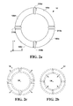
- FIG. 2 a is a top plan view of another embodiment of an angular rate sensor in accordance with the present invention.
- FIGS. 2 b and 2 c are top plan views illustrating an extension mode of the angular rate sensor of FIG. 2 a;
- FIGS. 3 a and 3 b are top plan views illustrating other example embodiments in which the angular rate sensor includes different numbers of proof masses;
- FIGS. 4 a , 4 b , and 4 c are top plan views of embodiments of the angular rate sensor of the present invention showing the use of a frame;
- FIG. 5 is a top plan view of an example of a more-detailed implementation of the angular rate sensor of the present invention.
- FIGS. 6 a and 6 b are top plan views of examples of an anchoring linkage and anchoring flexure of the angular rate sensor of the present invention
- FIG. 7 is a top plan view of an example linkage for use with the angular rate sensor of the present invention.
- FIG. 8 is a top plan view of another embodiment of the angular rate sensor of the present invention, a modification of the embodiment of FIG. 5 ;
- FIG. 9 is a top plan view of another embodiment of the angular rate sensor of the present invention, a modification of the embodiment of FIG. 8 ;
- FIG. 10 is a top plan view of another embodiment of the angular rate sensor of the present invention.
- FIG. 11 is a top plan view of another embodiment of the angular rate sensor of the present invention.
- FIGS. 12 a and 12 b are top plan and side elevational views illustrating sensing operation of an angular rate sensor of the present invention when the input axis is the X axis;
- FIGS. 13 a and 13 b are top plan and side elevational views illustrating sensing operation of an angular rate sensor of the present invention when the input axis is the Y axis;
- FIGS. 14 a and 14 b are top plan and side elevational views illustrating sensing operation of an angular rate sensor of the present invention when the input axis is the Z axis;
- FIGS. 15A-15H illustrate the basic steps of Nasiri-fabrication of an angular rate sensor of the present invention.
- the present invention relates to angular velocity sensors, and more particularly to a multi-axis angular velocity sensor having a single drive system.
- the following description is presented to enable one of ordinary skill in the art to make and use the invention and is provided in the context of a patent application and its requirements.
- Various modifications to the preferred embodiment and the generic principles and features described herein will be readily apparent to those skilled in the art.
- the present invention is not intended to be limited to the embodiment shown but is to be accorded the widest scope consistent with the principles and features described herein.
- a drive system of the disclosed single-drive angular rate sensor is based on an “extension” or “extending” vibratory mechanical mode.
- extension mode When a mechanical structure of the angular rate sensor is oscillated in the extension mode, the mechanical structure generates Coriolis forces around three orthogonal axes resulting from rotation of the angular rate sensor around three input axes.
- An advantage of the extension mode is the simplicity of the achievable design. Consequently, a significantly smaller size design is possible. This in turn reduces production costs.
- Another advantage of the disclosed angular rate sensor is a single drive mode.
- the single drive mode requires a single drive circuit, e.g., a circuit that includes a single pick-up circuit and a single oscillation loop circuit.
- the angular rate sensor of the present inventions allows the single drive system to be shared by multiple sensing systems, e.g., multiple axes of motion can be sensed when using the single drive system.
- MEMS microelectromechanical systems
- the base 10 can be provided as an appropriate substrate, the sensor components can be hermetically sealed, and/or other well-known MEMS techniques can be used.
- the angular rate sensor 8 may sense a rate of rotation of the sensor 8 , i.e. angular velocity, about at least one of three input axes.
- the X axis may be a first input axis
- the Y axis may be a second input axis
- a Z axis may be a third input axis.
- the angular rate sensor 8 includes a base 10 and a plurality of proof masses 100 , indicated specifically in FIG. 1 a as masses 100 a - d , disposed within a plane parallel to the base.
- the plane parallel to the base and defined by the masses 100 a - d i.e. the X-Y plane extending through the center of the masses 100 , is referred to herein as the “mass plane.”
- the proof masses 100 a - d in the described embodiment are multiple discrete masses and are shown to form a rectangle or square shape when viewed as in FIG. 1 a , but may be other shapes in other embodiments (e.g., as in FIG. 2 a described below).
- the masses 100 a - d can be substantially planar or flat, with a small (Z-axis) thickness relative to their length and width, where the masses lie substantially in the mass plane.
- the masses can have a length and/or width approximately 10-30 times the thickness, but can vary even more in other embodiments. Other embodiments can allow different mass thicknesses.
- the sensor further includes at least one actuator 400 to set the masses 100 a - d into motion within the mass plane, and at least one transducer 501 , 502 and/or 503 , to sense at least one Coriolis (external) force.
- the transducer 501 may sense motion around the X axis
- the transducer 502 may sense motion around the Y axis
- the transducer 503 may sense motion around the Z axis.
- the angular rate sensor can further include anchoring linkages 300 .
- the anchoring linkages 300 couple and suspend the masses 100 a - d to the base 10 .
- the angular rate sensor 8 includes a linkage 200 that flexibly couples the masses 100 a - d to each other, such that each mass 100 a - d is flexibly coupled to two of the other masses 100 a - d .
- the linkage 200 can include linkage portions as shown, where each linkage portion connects two adjacent proof masses 100 a - d , as described in greater detail below with respect to FIG. 7 .
- the angular rate sensor 8 may have an extension mode in which the masses 100 a - d move substantially in a plane and simultaneously move away ( FIG. 1 c ) or towards ( FIG. 1 b ) a center of mass CM defined by the masses 100 a - d .
- the center of mass CM of the masses 100 a - d is shown as an example, and is approximately in the same mass plane defined by the masses 100 a - d .
- the extension mode may be implemented using proof masses 100 a - d moving simultaneously inwards toward or outwards from the center of mass, wherein each mass moves along a line radiating substantially from the center of mass such that the center of mass of the masses 100 a - d does not substantially move, e.g., the masses 100 a - d all move approximately the same distance from the center of mass CM.
- the extension mode may be a drive mode of the angular rate sensor, such that the actuator(s) causes the extension mode movement of the masses 100 .
- the linkage 200 may constrain the plurality of masses to substantially move only in the extension mode.
- the extension mode is a mechanical resonant mode, in which the proof masses 100 a - d all follow the motion conforming to the shape (pattern of movement) of the extension mode at a single resonant frequency.
- the linkage 200 may make undesired resonant frequencies substantially higher than the resonant frequency of the extension mode. If the mechanical structure is operated by actuating the masses at the resonant frequency all masses move in the accordance to the extension mode. The motion of the structure at the resonant frequency of the extension mode causes a sufficient amount of oscillatory movement (mechanical amplitude) of the masses to allow accurate measurement of the resulting Coriolis force. This resonant frequency can be determined by experimentation, for example.
- the sensor of the present invention can include a single-drive system, in which a single drive circuit (not shown) is connected to the actuator.
- the single drive circuit can include a single pick-up circuit (including transducer(s) to measure the motion of the proof masses), a phase shifter (in some embodiments) to shift the phase of the measured signal, and a feedback circuit to provide the signal back to the actuator (e.g., drivers/amplifiers for providing the appropriate signal to the actuator).
- This single drive circuit may cause oscillations at mechanical resonant frequency.
- the masses 100 a - d can be driven into the motion conforming to the shape (pattern of movement) of the extension mode using actuator 400 , which is the single driven mode of the sensor.
- Coriolis forces resulting from the angular rate around multiple input axes can be sensed from the proof masses at the single drive frequency.
- multiple axes can be sensed based on the masses driven by a single actuator 400 , if desired.
- the sensor can use three transducers 501 , 502 , and 503 to sense angular motion of the masses about three different axes at the single drive frequency. This is advantageous in that only one set of drive circuitry is needed in a multi-axis sensing system, rather than a drive circuit needed for each sensed axis.
- FIG. 2 a is a top plan view of another embodiment of an angular rate sensor 12 in accordance with the present invention. Only the proof masses and the linkage are shown for clarity.
- each of the proof masses 100 a - d is curved such that the collective shape of the masses 100 a - d is substantially circular when viewed down on the mass plane.
- the angular rate sensor may comprise four masses 100 a - 100 d coupled through the linkage 200 , where linkage 200 includes linkage portions 210 a - d , each linkage portion 210 a - d connecting two adjacent ones of the masses 100 a - d , as described in greater detail below with respect to FIG. 7 .
- the angular rate sensor 12 may have an extension mode.
- a center of mass CM of the masses 100 a - d is shown as an example, and is approximately in the same mass plane defined by the masses 100 a - d .
- the masses 100 a - d simultaneously move outwardly from the center of mass CM in the extension mode.
- the masses 100 a - d simultaneously move inwardly toward the center of mass CM in the extension mode.
- a linkage portion 210 a connects proof mass 100 a and proof mass 100 b .
- the linkage portion 210 a allows mass 100 a and mass 100 b to move simultaneously along axes radiating from the center of the mass CM outwards, i.e. the linkage portion 210 a is substantially compliant with respect to that motion.
- the linkage portion 210 a allows mass 100 a and mass 100 b to move away from or towards each other along the axis orthogonal to the axis radiating from the center of mass outwards, i.e. the linkage portion 210 a is substantially compliant with respect to that motion.
- the linkage portion 210 a does not allow mass 100 a and mass 100 b to move in an opposite direction from each other along the axes radiating from the center of the structure, i.e. the linkage portion 210 a is substantially stiff with respect to that motion.
- the linkage portion 210 a does not allow mass 100 a and the mass 100 b to move in an opposite direction from each other along the axis normal to the base, i.e. the linkage portion 210 a is substantially stiff with respect to that motion.
- a linkage portion 210 b connects mass 100 b and mass 100 c
- a linkage portion 210 c connects mass 100 c and mass 100 d
- a linkage portion 210 d connects mass 100 a and mass 100 d .
- the linkage portions 210 b - 210 d have similar properties as the portion of the linkage 210 a which are described above.
- the overall stiffness of the structure comprising the masses 100 a - d and the linkage 210 a - d is substantially low with respect to any simultaneous extension or contraction of the masses 100 a - d in the mass plane, as when moving in the extension mode.
- any other combination of in-plane motion of the masses 100 a - d other than the motion defined by the extension mode may be designed to be substantially stiff.
- the overall out-of-plane stiffness of the structure is substantially high and the linkage portions 210 a - d may be designed so that the two neighboring masses are rigidly coupled in out-of-plane direction.
- the plurality of masses may be made substantially stiff for all motions except for motion in the extension mode.
- the linkage portions 210 a - d flex to accommodate the movement of the masses 100 a - d in the extension mode as shown in FIGS. 2 b and 2 c and are stiff in other axes, and therefore the linkage 200 constrains the masses to move only in the extension mode, i.e. only within the mass plane and simultaneously away or toward the center of mass of the masses.
- the masses 100 a - d consequently behave as a solid plate with respect to rotations about X, Y and Z axes.
- the extension mode may be a drive mode of the angular rate sensor, such that the actuator causes the extension mode movement.
- the drive mode can be a mechanical resonant mode in which the proof masses 100 a - d are driven at a resonant frequency of the mechanical structure, similarly as described above for the embodiment of FIGS. 1 a - 1 c .
- the center of mass does not substantially move as a result of the movement of masses 100 a - d.
- FIG. 3 a illustrates another example embodiment 14 in which the angular rate sensor may comprise three proof masses 100 a - 100 c coupled through the linkage 200 further comprising at least three linkage portions 210 a - 210 c and appropriate flexures. Only the proof masses and the linkage are shown for clarity. In the embodiment of FIG. 3 a , the masses form an approximate circle when viewed, as shown, above the mass plane defined by the masses 100 a - d . In other embodiments, other shapes of masses can be employed. Properties of the linkage and masses are similar to the properties of the linkage and masses as discussed in the embodiment above and shown in FIG. 2 a.
- the angular rate sensor may comprise a larger number of proof masses 100 coupled mutually through a linkage 200 further comprising multiple linkage portions 210 and appropriate flexures. Only the proof masses and the linkage are shown for clarity. Properties of the linkage and masses are similar to the properties of the linkage and masses as discussed in the embodiment above and shown in FIG. 2 a . Thus, a different number of masses and linkage portions can be used in various embodiments.
- an embodiment 18 of the angular rate sensor shows the use of a frame 250 .
- the linkage 200 may comprise the linkage portions 210 a - d and further comprise a substantially planar frame 250 that encircles or surrounds the masses 100 a - 100 d within the mass plane, i.e. the outsides of the masses within the mass plane are surrounded by the frame 250 .
- the linkage 200 may include frame flexures 280 a - d .
- Four frame flexures 280 a - d are shown in the described embodiment of FIG. 4 a , but other embodiments can provide different numbers of flame flexures.
- At least one of the masses 100 a - d may be flexibly coupled to the frame through a frame flexure 280 .
- each of the flexures 280 a - d may be substantially compliant in a direction along the axes radiating from the center of the mass CM within the mass plane, and may be substantially stiff in both the axis normal to the mass plane, and within the mass plane along the axis normal to the axis radiating from the center of the mass.
- a function of the frame 250 and flexures 280 is to enhance the overall out-of-plane stiffness of the structure.
- any motion of the masses 100 a - d relative to the frame 250 in an out-of-plane direction is substantially stiff.
- in-plane motion of any mass 100 relative to the frame 250 in the direction normal to the axis and radiating from the center of the mass outwards is substantially reduced. Consequently, by adding the frame 250 to the linkage 200 , the overall stiffness of the structure may be made substantially higher for all motions except for the desired motion in the extension mode, causing the structure to be even more “plate-like.”
- a frame 251 may be encircled or surrounded by the proof masses 100 , where the outside of the frame within the mass plane is surrounded by the masses 100 .
- the masses 100 are connected to the frame 251 by frame flexures 280 .
- a function of the frame is similar to the frame 250 encircling the masses 100 as explained above.
- the frame may be a multi-part frame that includes an inner first frame 251 encircled or surrounded by the plurality of masses 100 , and also including an outer second frame 250 encircling or surrounding the proof masses.
- the frames 251 and 250 may have the same functionality as the single-frame designs described above.
- the angular rate sensor 24 comprises four masses 100 a - d disposed in a plane.
- the four masses 100 a - d are coupled through the plurality of the linkage portions 210 a - d .
- the masses 100 a - d are encircled or surrounded by the frame 250 .
- the masses 100 a - d and the frame 250 are coupled through the frame flexures 280 a - h .
- the masses 100 a - d and the linkage 200 form a stiff, plate-like structure.
- the linkage 200 constrains the masses such that the only substantial allowable motion is that of the masses 100 a - d moving in the extension mode in the mass plane.
- one or more transducers may be added to the sensor in order to sense Coriolis forces induced on the masses 100 .
- the transducers may be capacitive.
- the transducer includes a pair of electrodes 501 a - b that may be placed underneath the frame 250 (with respect to the view of FIG. 5 ) such that in response to the frame 250 and masses 100 rotating around the first axis, the transducer 501 a - b senses Coriolis force.
- the transducer 501 a - b senses Coriolis force.
- the second input axis i.e.
- a transducer includes a pair of electrodes 502 a - b that may be placed underneath the frame 250 such that in response to the frame 250 and masses 100 rotating around the second axis, the transducer 502 a - b detects Coriolis force.
- a transducer for the third input axis may be implemented as an in-plane capacitor.
- the Z-axis transducer may be a lateral comb capacitor, as shown. In another implementation it may be a parallel plate capacitor.
- the transducer includes at least one pair of electrodes 503 a - b , where a pair of electrodes 503 a - b may be placed at one or more locations around the frame 250 such that in response to the frame 250 and masses 100 rotating around the third axis, the transducer(s) 503 a - b detect Coriolis force-induced motion.
- the transducers 501 a - b , 502 a - b and 503 a - b may be single-ended, i.e., only one of the transducer components 501 a or 501 b , 502 a or 502 b , and 503 a or 503 b , need be used.
- the transducers 501 a - b , 502 a - b and 503 a - b may be attached directly to the masses 100 a - d .
- transducers 501 and 502 may be provided beneath the masses 100 a - d instead of beneath frame 250 as shown, and in other implementations the transducer 503 may be coupled to the masses 100 a - d instead of the frame 250 as shown (e.g. in embodiments without a frame 250 , or alternatively in embodiments including a frame).
- the four masses 100 a - d can be flexibly coupled to the base 10 through a plurality of anchoring linkages 300 a - d .
- the anchoring linkages 300 a - d are compliant so that masses 100 a - d may move in the extension mode.
- the anchoring linkages 300 a - d are also compliant so that the masses 100 a - d and frame 250 can move substantially together around the X axis, and are compliant so that the masses 100 a - d and frame 250 to move substantially together around the Y axis.
- the anchoring linkages 300 a - d are compliant so that the masses 100 a - d and frame 250 can move substantially together around the Z axis.
- Each anchoring linkage 300 may comprise an actuator mass 331 , an anchoring flexure 340 and a coupling flexure 350 .
- the anchoring flexure 340 ensures that the actuator mass moves within the mass plane approximately along the line radiating from the center of mass (or approximately in a similar direction).
- the anchoring flexure is substantially stiff to rotation around the axis normal to the plane. This feature ensures that no parasitic Coriolis-like motion around the axis normal to the plane occurs on the associated mass 100 that is coupled to the anchoring linkage 300 .
- the anchoring flexure 340 is shown in FIG. 6 b .
- the anchoring flexure may be a folded flexure comprising two actuator guiding arms 341 a - b and a total of eight beams 342 a - h .
- Other configurations and number of guiding arms and beams can be used in other embodiments.
- an actuator 400 including components 400 a - d may be used to set actuator mass 331 into motion.
- the associated mass 100 coupled to the mass 331 is set into motion through coupling flexure 350 that is substantially stiff along the axis radiating from the center of the mass so that actuator mass 331 and the mass 100 move substantially together in extension mode.
- the actuator may be electrostatic, for example.
- the motion of each mass 100 may be sensed in-plane by one or more appropriate transducers.
- the motion of each actuator mass 331 may be sensed in-plane by one or more appropriate transducers.
- the transducers may be capacitive, for example. Some embodiments may include the transducers as some of the components 400 a - d .
- components 400 a and 400 c may be actuators
- components 400 b and 400 d may be transducers that measure motion of the actuator mass 331 and the associated mass 100 to provide a feedback drive signal to the actuators.
- each component 400 a - d may be split to include an actuator as well as a transducer.
- the coupling flexure 350 may comprise two parallel beams 351 a - b .
- the beams 351 a - b may be considered a single beam that is split into two components. By adjusting one or more of these two components, out-of-plane stiffness of the coupling flexure 350 is preserved while in-plane and torsional stiffness of the coupling flexure can be easily adjusted to substantially match each other.
- the linkage 200 comprises the frame 250 , the linkage portions 210 , and the frame flexures 280 .
- the masses 100 are flexibly coupled to the linkage 200 .
- the linkage portions 210 may each comprise mass flexures 211 a and 211 b and a mass guiding arm 212 , in which the mass flexures 211 couple the mass guiding arm 212 to a mass on either side of the mass guiding arm 212 , such as mass 100 a and mass 100 b , or mass 100 a and mass 100 c . Additional mass flexures 211 can be used in other embodiments.
- the frame flexures 280 may each comprise mass flexures 281 and a mass guiding arm 282 , in which one mass flexure 281 couples the mass guiding arm 282 to the frame 250 , and the other mass flexure 281 couples the mass guiding arm 282 to a mass 100 .
- Additional mass flexures 281 can be used in other embodiments. Other embodiments can use different forms of flexures and linkage portions.
- FIG. 8 another embodiment 26 of the angular rate sensor of the present invention is shown, a modification of the embodiment of FIG. 5 .
- Anchoring linkages of FIG. 5 are replaced by an inner frame 251 .
- the inner frame 251 is flexibly coupled to the base 10 through coupling linkage 355 a - d .
- Coupling linkages 355 a - d have similar stiffness properties as coupling linkage 350 from FIGS. 5 and 6 a .
- Masses 100 a - d are flexibly coupled to the inner frame through frame flexures 280 i - p .
- the actuators 400 a - d are attached directly to the masses 100 a - d and may drive the masses 100 a - d into motion.
- Functionality of the portion of the linkage 210 a - d , the frame 250 , frame flexures 280 a - h and transducers 501 - 503 are similar to that of the embodiment shown in FIG
- FIG. 9 another embodiment 28 of the angular rate sensor of the present invention is shown, a modification of the embodiment from FIG. 8 .
- the linkage portions 210 a - d is removed.
- the extension mode is a resonant mode of the structure and by driving the masses using the actuator 400 a - d , masses may be set in motion along the shape of the extension mode.
- FIG. 10 another embodiment 30 of the angular rate sensor of the present invention is shown.
- the masses 100 a - d are flexibly coupled to the frame 250 through frame flexures 285 a - h .
- the frame 250 is flexibly coupled to the base 10 through coupling springs 360 a - d .
- the masses 100 a - d may be set in motion by a set of actuators 400 a - d .
- the frame flexures 285 a - d ensure that the masses 100 a - d are allowed to move substantially along the axis radiating from the center of mass of the masses 100 a - d .
- the frame flexures 285 a - d ensures that the masses 100 a - d are restricted to move out-of plane and are restricted to move around the axis normal to the base and relative to the frame 250 .
- Coupling flexures 360 a - d allow the frame 250 and the masses 100 a - d to rotate about the X axis.
- Coupling flexures 360 a - d allow the frame 250 and the masses 100 a - d to rotate about the Y axis.
- Coupling flexures 360 a - d allow the frame 250 and the masses 100 a - d to rotate about the Z axis.
- the extension mode is a resonant mode of the structure and by driving the masses by the actuator 400 a - d masses may be set in motion conforming to the shape of the extension mode.
- FIG. 11 is a top plan view of another embodiment 32 of the angular rate sensor of the present invention.
- the shape of the rate sensor when viewed from a top view down on the mass plane is substantially circular.
- Other shapes of masses and linkages can be used in the sensor in other embodiments.
- the operation and components of angular rate sensor 32 are substantially similar to that sensor 24 described above.
- the angular rate sensor of the present invention senses angular velocity about one or more sensing axes.
- FIGS. 12 a , 12 b , 13 a , 13 b , 14 a and 14 c illustrate the operation of the angular rate sensor for different input rotation axes.
- FIGS. 12 a and 12 b illustrate the sensing operation when the input axis is the X axis, where FIG. 12 a is a top plan view and FIG. 12 b is a side elevational view.
- actuator 400 is controlled to set the motion of masses 100 such that the masses oscillate in extension mode substantially at the known resonant frequency of the moving mechanical structure in the extension mode.
- the angular rate sensor e.g., base 10
- experiences a rate of rotation around the X axis e.g.
- FIGS. 13 a and 13 b illustrate the sensing operation when the input axis is the Y axis, where FIG. 13 a is a top plan view and FIG. 13 b is a side elevational view.
- the angular rate sensor e.g., base 10
- a Coriolis force will act on masses 100 b and 100 d in opposite directions along the axis normal to the mass plane at the frequency of the extension mode.
- the transducer 502 a - b differentially senses motion of the frame 250 .
- FIGS. 14 a and 14 b illustrate top plan views of the angular rate sensor to illustrate the sensing operation when the input axis is the Z axis.
- the angular rate sensor e.g., base 10
- a Coriolis force will act on masses 100 a - d such that generated torque is normal to the mass plane at the frequency of the extension mode. Since the linkage 200 is stiff in the directions normal to the mass plane, resulting Coriolis forces will cause masses 100 together with the frame 250 to rotate around the Z axis.
- the transducer 503 a - b differentially senses motion of the frame 250 .
- FIG. 14 b shows an example of a result after the frame 250 and masses 100 have rotated counterclockwise about the Z axis, as sensed by the transducer 503 a - b.
- angular rate sensor can perform additional sensing for other types of external stresses besides the Coriolis force.
- input forces can be provided such as angular acceleration, which results in measuring acceleration instead of (or in addition to) the Coriolis forces as measured in the embodiments described above.
- Components to receive and sense such angular acceleration forces are known to those of skill in the art.
- Some embodiments of the angular rate sensor of the present invention can be fabricated as a MEMS device.
- An important process step of fabrication of a low cost MEMS device is the integration of mechanical parts with the electronics.
- a “Nasiri-Fabrication” platform may be utilized which is described for example in U.S. Pat. No. 7,104,129, entitled “Vertically Integrated MEMS Structure with Electronics in a Hermetically Sealed Cavity”, assigned to the assignee of this application and incorporated herein by reference in its entirety.
- This fabrication process makes use of bulk micromachining and readily allows for the water level integration of the MEMS substrate and the electronics (ASIC) substrate.
- this method encapsulates the mechanical parts in a low pressure hermetically sealed chamber that protects the MEMS device against adverse effect of environment such as humidity.
- FIGS. 15A-15H The basic steps of Nasiri-fabrication are shown in FIGS. 15A-15H .
- a handle wafer 40 is etched to form cavities as shown in FIG. 15A and FIG. 15B .
- Oxide is then grown on the handle wafer 40 .
- a handle wafer 40 and a device wafer 45 are then fusion bonded together as shown in FIG. 15C .
- the assembly comprising handle wafer 40 and the device wafer 45 is polished to achieve desired device thickness as shown in FIG. 15D .
- the device wafer 45 is then etched to form stand-offs 73 as shown in FIG. 15E .
- the stand-offs 73 are then covered by germanium 71 as shown in FIG. 15F .
- the device wafer 45 is then etched to form portions of MEMS device as shown in FIG.
- the MEMS device may be any of the embodiments of the disclosed angular rate sensor of the present invention comprising the masses 100 , the linkage 200 , the anchoring linkage 300 , the actuator 400 , and the lateral transducer 503 , for example.
- the handle and the device wafers are then eutetically bonded to the ASIC wafer 50 with exposed aluminum 72 at bonding points.
- the transducers 501 and 502 may be formed between aluminum deposited on ASIC wafer and MEMS device layer comprising proof masses 100 (or frame 250 ).
- the handle wafer 40 , the device wafer 45 and the ASIC wafer 50 may form a base 10 .
Abstract
Description
Claims (27)
Priority Applications (7)
| Application Number | Priority Date | Filing Date | Title |
|---|---|---|---|
| US12/558,398 US8534127B2 (en) | 2009-09-11 | 2009-09-11 | Extension-mode angular velocity sensor |
| US13/361,261 US9097524B2 (en) | 2009-09-11 | 2012-01-30 | MEMS device with improved spring system |
| US13/564,615 US8347717B2 (en) | 2009-09-11 | 2012-08-01 | Extension-mode angular velocity sensor |
| US13/966,026 US9052194B2 (en) | 2009-09-11 | 2013-08-13 | Extension-mode angular velocity sensor |
| US14/698,451 US9683844B2 (en) | 2009-09-11 | 2015-04-28 | Extension-mode angular velocity sensor |
| US14/800,612 US9891053B2 (en) | 2009-09-11 | 2015-07-15 | MEMS device with improved spring system |
| US15/866,140 US10551193B2 (en) | 2009-09-11 | 2018-01-09 | MEMS device with improved spring system |
Applications Claiming Priority (1)
| Application Number | Priority Date | Filing Date | Title |
|---|---|---|---|
| US12/558,398 US8534127B2 (en) | 2009-09-11 | 2009-09-11 | Extension-mode angular velocity sensor |
Related Child Applications (3)
| Application Number | Title | Priority Date | Filing Date |
|---|---|---|---|
| US13/361,261 Continuation-In-Part US9097524B2 (en) | 2009-09-11 | 2012-01-30 | MEMS device with improved spring system |
| US13/564,615 Continuation US8347717B2 (en) | 2009-09-11 | 2012-08-01 | Extension-mode angular velocity sensor |
| US13/966,026 Continuation US9052194B2 (en) | 2009-09-11 | 2013-08-13 | Extension-mode angular velocity sensor |
Publications (2)
| Publication Number | Publication Date |
|---|---|
| US20110061460A1 US20110061460A1 (en) | 2011-03-17 |
| US8534127B2 true US8534127B2 (en) | 2013-09-17 |
Family
ID=43729160
Family Applications (4)
| Application Number | Title | Priority Date | Filing Date |
|---|---|---|---|
| US12/558,398 Active 2032-07-04 US8534127B2 (en) | 2009-09-11 | 2009-09-11 | Extension-mode angular velocity sensor |
| US13/564,615 Active US8347717B2 (en) | 2009-09-11 | 2012-08-01 | Extension-mode angular velocity sensor |
| US13/966,026 Active US9052194B2 (en) | 2009-09-11 | 2013-08-13 | Extension-mode angular velocity sensor |
| US14/698,451 Active US9683844B2 (en) | 2009-09-11 | 2015-04-28 | Extension-mode angular velocity sensor |
Family Applications After (3)
| Application Number | Title | Priority Date | Filing Date |
|---|---|---|---|
| US13/564,615 Active US8347717B2 (en) | 2009-09-11 | 2012-08-01 | Extension-mode angular velocity sensor |
| US13/966,026 Active US9052194B2 (en) | 2009-09-11 | 2013-08-13 | Extension-mode angular velocity sensor |
| US14/698,451 Active US9683844B2 (en) | 2009-09-11 | 2015-04-28 | Extension-mode angular velocity sensor |
Country Status (1)
| Country | Link |
|---|---|
| US (4) | US8534127B2 (en) |
Cited By (17)
| Publication number | Priority date | Publication date | Assignee | Title |
|---|---|---|---|---|
| US20120125099A1 (en) * | 2010-11-23 | 2012-05-24 | Rolf Scheben | Yaw-rate sensor and method for operating a yaw-rate sensor |
| US20120152019A1 (en) * | 2010-11-29 | 2012-06-21 | Burkhard Kuhlmann | Yaw-rate sensor and method for operating a yaw-rate sensor |
| US20130167636A1 (en) * | 2011-12-28 | 2013-07-04 | Maxim Integrated Products, Inc. | Micro rate of rotation sensor and method for operating a micro rate of rotation sensor |
| US8616057B1 (en) * | 2010-01-23 | 2013-12-31 | Minyao Mao | Angular rate sensor with suppressed linear acceleration response |
| US20150226558A1 (en) * | 2009-09-11 | 2015-08-13 | Invensense, Inc. | Extension-mode angular velocity sensor |
| US9278847B2 (en) | 2008-12-23 | 2016-03-08 | Stmicroelectronics S.R.L. | Microelectromechanical gyroscope with enhanced rejection of acceleration noises |
| US9404747B2 (en) | 2013-10-30 | 2016-08-02 | Stmicroelectroncs S.R.L. | Microelectromechanical gyroscope with compensation of quadrature error drift |
| US9470526B2 (en) | 2008-11-26 | 2016-10-18 | Stmicroelectronics S.R.L. | Microelectromechanical gyroscope with rotary driving motion and improved electrical properties |
| US9593948B2 (en) | 2007-11-15 | 2017-03-14 | Robert Bosch Gmbh | Yaw-rate sensor |
| US9891053B2 (en) | 2009-09-11 | 2018-02-13 | Invensense, Inc. | MEMS device with improved spring system |
| US10119823B2 (en) | 2014-04-22 | 2018-11-06 | Seiko Epson Corporation | Angular velocity sensor, electronic apparatus, and mobile object |
| US10168154B2 (en) | 2009-12-24 | 2019-01-01 | Stmicroelectronics S.R.L. | Integrated microelectromechanical gyroscope with improved driving structure |
| US20190212144A1 (en) * | 2018-01-11 | 2019-07-11 | Invensense, Inc. | Proof mass offset compensation |
| US10598690B2 (en) | 2011-09-12 | 2020-03-24 | Stmicroelectronics S.R.L. | Microelectromechanical device incorporating a gyroscope and an accelerometer |
| RU2723141C1 (en) * | 2019-06-07 | 2020-06-09 | Акционерное Общество "Государственное Машиностроительное Конструкторское Бюро "Радуга" Имени А.Я. Березняка" | Angular speed sensor |
| US10849205B2 (en) | 2015-10-14 | 2020-11-24 | Current Lighting Solutions, Llc | Luminaire having a beacon and a directional antenna |
| US20230010336A1 (en) * | 2019-12-06 | 2023-01-12 | Senodia Technologies (Shaoxing) Co., Ltd. | Three-axis microelectromechanical system (mems) gyroscope |
Families Citing this family (62)
| Publication number | Priority date | Publication date | Assignee | Title |
|---|---|---|---|---|
| CN101910789B (en) * | 2008-01-07 | 2012-02-29 | 株式会社村田制作所 | Angular velocity sensor |
| DE102008002748A1 (en) * | 2008-06-27 | 2009-12-31 | Sensordynamics Ag | Microgyroscope |
| DE502008002421D1 (en) * | 2008-11-11 | 2011-03-03 | Fraunhofer Ges Forschung | Micromechanical Coriolis rotation rate sensor |
| IT1391973B1 (en) | 2008-11-26 | 2012-02-02 | St Microelectronics Rousset | MONO OR BIASSIAL MICROELECTROMECHANICAL GYROSCOPE WITH INCREASED SENSITIVITY TO THE ANGULAR SPEED DETECTION |
| ITTO20090489A1 (en) * | 2008-11-26 | 2010-12-27 | St Microelectronics Srl | READING CIRCUIT FOR A MULTI-AXIS MEMS GYROSCOPE WITH DETECTED DETECTION DIRECTIONS COMPARED TO THE REFERENCE AXES, AND CORRESPONDING MEMS MULTI-AXIS GIROSCOPE |
| DE102009001248B4 (en) * | 2009-02-27 | 2020-12-17 | Hanking Electronics, Ltd. | MEMS gyroscope for determining rotational movements around an x, y or z axis |
| IT1394007B1 (en) | 2009-05-11 | 2012-05-17 | St Microelectronics Rousset | MICROELETTROMECANICAL STRUCTURE WITH IMPROVED REJECTION OF ACCELERATION DISORDERS |
| US9003882B1 (en) * | 2010-11-03 | 2015-04-14 | Georgia Tech Research Corporation | Vibratory tuning fork based six-degrees of freedom inertial measurement MEMS device |
| WO2012131682A1 (en) * | 2011-03-31 | 2012-10-04 | Ramot At Tel-Aviv University Ltd. | Compliant structures with time-varying moment of inertia |
| US9714842B2 (en) * | 2011-09-16 | 2017-07-25 | Invensense, Inc. | Gyroscope self test by applying rotation on coriolis sense mass |
| US8833162B2 (en) * | 2011-09-16 | 2014-09-16 | Invensense, Inc. | Micromachined gyroscope including a guided mass system |
| US9170107B2 (en) * | 2011-09-16 | 2015-10-27 | Invensense, Inc. | Micromachined gyroscope including a guided mass system |
| US10914584B2 (en) | 2011-09-16 | 2021-02-09 | Invensense, Inc. | Drive and sense balanced, semi-coupled 3-axis gyroscope |
| US9863769B2 (en) * | 2011-09-16 | 2018-01-09 | Invensense, Inc. | MEMS sensor with decoupled drive system |
| US20130201316A1 (en) | 2012-01-09 | 2013-08-08 | May Patents Ltd. | System and method for server based control |
| JP5708535B2 (en) * | 2012-03-13 | 2015-04-30 | 株式会社デンソー | Angular velocity sensor |
| JP6338813B2 (en) * | 2012-04-03 | 2018-06-06 | セイコーエプソン株式会社 | Gyro sensor and electronic device using the same |
| DE102012207937A1 (en) * | 2012-05-11 | 2013-11-14 | Robert Bosch Gmbh | Yaw rate sensor |
| JP6191151B2 (en) * | 2012-05-29 | 2017-09-06 | 株式会社デンソー | Physical quantity sensor |
| US9310202B2 (en) * | 2012-07-09 | 2016-04-12 | Freescale Semiconductor, Inc. | Angular rate sensor with quadrature error compensation |
| DE102012219550A1 (en) * | 2012-10-25 | 2014-04-30 | Robert Bosch Gmbh | Hybrid integrated component |
| US9547095B2 (en) * | 2012-12-19 | 2017-01-17 | Westerngeco L.L.C. | MEMS-based rotation sensor for seismic applications and sensor units having same |
| DE102013206414A1 (en) * | 2013-04-11 | 2014-10-16 | Robert Bosch Gmbh | Yaw rate sensor |
| EP3019442A4 (en) | 2013-07-08 | 2017-01-25 | Motion Engine Inc. | Mems device and method of manufacturing |
| WO2015042700A1 (en) | 2013-09-24 | 2015-04-02 | Motion Engine Inc. | Mems components and method of wafer-level manufacturing thereof |
| WO2015013827A1 (en) | 2013-08-02 | 2015-02-05 | Motion Engine Inc. | Mems motion sensor for sub-resonance angular rate sensing |
| DE102013215587A1 (en) * | 2013-08-07 | 2015-02-12 | Robert Bosch Gmbh | Method and device for adjusting the dynamic range of a rotation rate sensor |
| WO2015045621A1 (en) * | 2013-09-26 | 2015-04-02 | 株式会社村田製作所 | Angular velocity detection element |
| EP2884229B1 (en) * | 2013-09-30 | 2018-09-19 | InvenSense, Inc. | Micromachined gyroscope including a guided mass system |
| US20150102437A1 (en) * | 2013-10-14 | 2015-04-16 | Freescale Semiconductor, Inc. | Mems sensor device with multi-stimulus sensing and method of fabrication |
| WO2015103688A1 (en) | 2014-01-09 | 2015-07-16 | Motion Engine Inc. | Integrated mems system |
| US9958271B2 (en) | 2014-01-21 | 2018-05-01 | Invensense, Inc. | Configuration to reduce non-linear motion |
| FI126071B (en) * | 2014-01-28 | 2016-06-15 | Murata Manufacturing Co | Improved gyroscope design and gyroscope |
| FI126070B (en) | 2014-01-28 | 2016-06-15 | Murata Manufacturing Co | Improved ring gyroscope design and gyroscope |
| WO2015154173A1 (en) | 2014-04-10 | 2015-10-15 | Motion Engine Inc. | Mems pressure sensor |
| CN105043370B (en) * | 2014-04-29 | 2019-01-22 | 财团法人工业技术研究院 | Micro-motor device with fulcrum element |
| WO2015184531A1 (en) | 2014-06-02 | 2015-12-10 | Motion Engine Inc. | Multi-mass mems motion sensor |
| DE102014211646A1 (en) | 2014-06-18 | 2015-12-24 | Robert Bosch Gmbh | Micromechanical sensor component for a rotation rate sensor |
| EP2963387B1 (en) | 2014-06-30 | 2019-07-31 | STMicroelectronics Srl | Micro-electro-mechanical device with compensation of errors due to disturbance forces, such as quadrature components |
| US10247554B2 (en) * | 2014-09-24 | 2019-04-02 | The Regents Of The University Of California | Fully balanced micro-machined inertial sensor |
| US11287486B2 (en) | 2014-12-09 | 2022-03-29 | Motion Engine, Inc. | 3D MEMS magnetometer and associated methods |
| CA3220839A1 (en) | 2015-01-15 | 2016-07-21 | Motion Engine Inc. | 3d mems device with hermetic cavity |
| CN104931032B (en) * | 2015-06-26 | 2018-04-10 | 清华大学 | A kind of mass MEMS resonant formula gyroscope of single anchor point four |
| US9879996B2 (en) * | 2015-11-30 | 2018-01-30 | General Electric Company | System and method of electrostatic carouseling for gyrocompassing |
| US10359284B2 (en) * | 2015-12-10 | 2019-07-23 | Invensense, Inc. | Yaw rate gyroscope robust to linear and angular acceleration |
| US10696541B2 (en) | 2016-05-26 | 2020-06-30 | Honeywell International Inc. | Systems and methods for bias suppression in a non-degenerate MEMS sensor |
| US10371521B2 (en) | 2016-05-26 | 2019-08-06 | Honeywell International Inc. | Systems and methods for a four-mass vibrating MEMS structure |
| JP6639377B2 (en) | 2016-12-08 | 2020-02-05 | 株式会社東芝 | Vibration device |
| CN107192384B (en) * | 2017-07-24 | 2022-04-05 | 深迪半导体(绍兴)有限公司 | MEMS triaxial gyroscope |
| US20200294401A1 (en) | 2017-09-04 | 2020-09-17 | Nng Software Developing And Commercial Llc. | A Method and Apparatus for Collecting and Using Sensor Data from a Vehicle |
| JP6849042B2 (en) * | 2018-12-19 | 2021-03-24 | 株式会社村田製作所 | Vibration-resistant multi-axis gyroscope |
| KR102087840B1 (en) * | 2019-02-07 | 2020-03-11 | 고려대학교 산학협력단 | Strain sensor and method for manufacturing the same |
| EP3696503B1 (en) * | 2019-02-15 | 2022-10-26 | Murata Manufacturing Co., Ltd. | Vibration-robust multiaxis gyroscope |
| US11060866B2 (en) * | 2019-02-15 | 2021-07-13 | Murata Manufacturing Co., Ltd. | Balanced multiaxis gyroscope |
| EP3888346A4 (en) | 2019-02-19 | 2022-08-24 | Edgy Bees Ltd. | Estimating real-time delay of a video data stream |
| CN112556675B (en) * | 2019-09-10 | 2023-03-07 | 昇佳电子股份有限公司 | Micro-electromechanical gyroscope |
| EP3971522B1 (en) * | 2020-05-25 | 2023-06-28 | Murata Manufacturing Co., Ltd. | Multiaxis gyroscope with supplementary masses |
| US11686581B2 (en) | 2020-06-08 | 2023-06-27 | Analog Devices, Inc. | Stress-relief MEMS gyroscope |
| US11692825B2 (en) * | 2020-06-08 | 2023-07-04 | Analog Devices, Inc. | Drive and sense stress relief apparatus |
| US11698257B2 (en) * | 2020-08-24 | 2023-07-11 | Analog Devices, Inc. | Isotropic attenuated motion gyroscope |
| IT202100020504A1 (en) * | 2021-07-30 | 2023-01-30 | St Microelectronics Srl | MEMS GYROSCOPE HAVING IMPROVED SQUARE ERROR REJECTION |
| CN116026298B (en) * | 2023-03-27 | 2023-06-16 | 中国人民解放军国防科技大学 | Vibration gyro measurement and control method and device based on vibration mode control |
Citations (111)
| Publication number | Priority date | Publication date | Assignee | Title |
|---|---|---|---|---|
| US4511848A (en) | 1983-06-15 | 1985-04-16 | Watson Industries, Inc. | Synchronous AM demodulator with quadrature signal cancellation |
| US4736629A (en) | 1985-12-20 | 1988-04-12 | Silicon Designs, Inc. | Micro-miniature accelerometer |
| US5083466A (en) | 1988-07-14 | 1992-01-28 | University Of Hawaii | Multidimensional force sensor |
| US5359893A (en) | 1991-12-19 | 1994-11-01 | Motorola, Inc. | Multi-axes gyroscope |
| US5367194A (en) | 1990-10-29 | 1994-11-22 | Hewlett-Packard Company | Microchip assembly with electrical element in sealed cavity |
| US5481914A (en) | 1994-03-28 | 1996-01-09 | The Charles Stark Draper Laboratory, Inc. | Electronics for coriolis force and other sensors |
| US5635638A (en) | 1995-06-06 | 1997-06-03 | Analog Devices, Inc. | Coupling for multiple masses in a micromachined device |
| US5656778A (en) | 1995-04-24 | 1997-08-12 | Kearfott Guidance And Navigation Corporation | Micromachined acceleration and coriolis sensor |
| US5659195A (en) | 1995-06-08 | 1997-08-19 | The Regents Of The University Of California | CMOS integrated microsensor with a precision measurement circuit |
| US5703292A (en) | 1994-03-28 | 1997-12-30 | The Charles Stark Draper Laboratory, Inc. | Sensor having an off-frequency drive scheme and a sense bias generator utilizing tuned circuits |
| US5703293A (en) | 1995-05-27 | 1997-12-30 | Robert Bosch Gmbh | Rotational rate sensor with two acceleration sensors |
| US5780740A (en) | 1995-10-27 | 1998-07-14 | Samsung Electronics Co., Ltd. | Vibratory structure, method for controlling natural frequency thereof, and actuator, sensor, accelerator, gyroscope and gyroscope natural frequency controlling method using vibratory structure |
| US5895850A (en) | 1994-04-23 | 1999-04-20 | Robert Bosch Gmbh | Micromechanical resonator of a vibration gyrometer |
| US5915168A (en) | 1996-08-29 | 1999-06-22 | Harris Corporation | Lid wafer bond packaging and micromachining |
| US5992233A (en) | 1996-05-31 | 1999-11-30 | The Regents Of The University Of California | Micromachined Z-axis vibratory rate gyroscope |
| US5996409A (en) | 1997-05-10 | 1999-12-07 | Robert Bosch Gmbh | Acceleration sensing device |
| US6036872A (en) | 1998-03-31 | 2000-03-14 | Honeywell Inc. | Method for making a wafer-pair having sealed chambers |
| US6122961A (en) | 1997-09-02 | 2000-09-26 | Analog Devices, Inc. | Micromachined gyros |
| US6134961A (en) | 1998-06-24 | 2000-10-24 | Aisin Seiki Kabushiki Kaisha | Angular velocity sensor |
| US6153917A (en) | 1998-03-16 | 2000-11-28 | Akebono Brake Industry Co., Ltd. | Semiconductor acceleration sensor and manufacturing method thereof |
| US6189381B1 (en) | 1999-04-26 | 2001-02-20 | Sitek, Inc. | Angular rate sensor made from a structural wafer of single crystal silicon |
| US6229190B1 (en) | 1998-12-18 | 2001-05-08 | Maxim Integrated Products, Inc. | Compensated semiconductor pressure sensor |
| US6230563B1 (en) | 1998-06-09 | 2001-05-15 | Integrated Micro Instruments, Inc. | Dual-mass vibratory rate gyroscope with suppressed translational acceleration response and quadrature-error correction capability |
| US6230564B1 (en) | 1998-02-19 | 2001-05-15 | Akebono Brake Industry Co., Ltd. | Semiconductor acceleration sensor and its self-diagnosing method |
| US6250156B1 (en) | 1996-05-31 | 2001-06-26 | The Regents Of The University Of California | Dual-mass micromachined vibratory rate gyroscope |
| US6250157B1 (en) | 1998-06-22 | 2001-06-26 | Aisin Seiki Kabushiki Kaisha | Angular rate sensor |
| US6370937B2 (en) | 2000-03-17 | 2002-04-16 | Microsensors, Inc. | Method of canceling quadrature error in an angular rate sensor |
| US20020051258A1 (en) | 2000-06-23 | 2002-05-02 | Murata Manufacturing Co., Ltd. | Composite sensor device and method of producing the same |
| US6391673B1 (en) | 1999-11-04 | 2002-05-21 | Samsung Electronics Co., Ltd. | Method of fabricating micro electro mechanical system structure which can be vacuum-packed at wafer level |
| US6405592B1 (en) * | 1997-06-19 | 2002-06-18 | Stmicrlelectronics S.R.L. | Hermetically-sealed sensor with a movable microstructure |
| US6426687B1 (en) | 2001-05-22 | 2002-07-30 | The Aerospace Corporation | RF MEMS switch |
| US6433411B1 (en) | 2000-05-22 | 2002-08-13 | Agere Systems Guardian Corp. | Packaging micromechanical devices |
| US6430998B2 (en) | 1999-12-03 | 2002-08-13 | Murata Manufacturing Co., Ltd. | Resonant element |
| US6445195B1 (en) | 2000-08-02 | 2002-09-03 | The Charles Stark Draper Laboratory, Inc. | Drive feedthrough nulling system |
| US6448109B1 (en) | 2000-11-15 | 2002-09-10 | Analog Devices, Inc. | Wafer level method of capping multiple MEMS elements |
| US6452238B1 (en) | 1999-10-04 | 2002-09-17 | Texas Instruments Incorporated | MEMS wafer level package |
| US6480320B2 (en) | 2001-02-07 | 2002-11-12 | Transparent Optical, Inc. | Microelectromechanical mirror and mirror array |
| US6479320B1 (en) | 2000-02-02 | 2002-11-12 | Raytheon Company | Vacuum package fabrication of microelectromechanical system devices with integrated circuit components |
| US6481285B1 (en) | 1999-04-21 | 2002-11-19 | Andrei M. Shkel | Micro-machined angle-measuring gyroscope |
| US6481283B1 (en) | 1999-04-05 | 2002-11-19 | Milli Sensor Systems & Actuators, Inc. | Coriolis oscillating gyroscopic instrument |
| US6494096B2 (en) | 2000-03-16 | 2002-12-17 | Denso Corporation | Semiconductor physical quantity sensor |
| US20020189353A1 (en) * | 2001-06-19 | 2002-12-19 | Knowles Gary R. | Coupled micromachined structure |
| US20020189352A1 (en) | 2001-06-19 | 2002-12-19 | Reeds John William | Mems sensor with single central anchor and motion-limiting connection geometry |
| US6508122B1 (en) | 1999-09-16 | 2003-01-21 | American Gnc Corporation | Microelectromechanical system for measuring angular rate |
| US6508125B2 (en) | 2000-09-07 | 2003-01-21 | Mitsubishi Denki Kabushiki Kaisha | Electrostatic capacitance type acceleration sensor, electrostatic capacitance type angular acceleration sensor and electrostatic actuator |
| US6519075B2 (en) | 2000-11-03 | 2003-02-11 | Agere Systems Inc. | Packaged MEMS device and method for making the same |
| US6520017B1 (en) * | 1999-08-12 | 2003-02-18 | Robert Bosch Gmbh | Micromechanical spin angular acceleration sensor |
| US6528344B2 (en) | 2000-06-22 | 2003-03-04 | Samsung Electronics Co., Ltd. | Chip scale surface-mountable packaging method for electronic and MEMS devices |
| US6539804B1 (en) | 1998-06-22 | 2003-04-01 | Kabushiki Kaisha Tokai Rika Denki Seisakusho | Two-axis yaw rate sensor |
| US20030074967A1 (en) | 1999-07-08 | 2003-04-24 | California Institute Of Technology | Microgyroscope with integrated vibratory element |
| US6555417B2 (en) | 2000-12-05 | 2003-04-29 | Analog Devices, Inc. | Method and device for protecting micro electromechanical system structures during dicing of a wafer |
| US6559530B2 (en) | 2001-09-19 | 2003-05-06 | Raytheon Company | Method of integrating MEMS device with low-resistivity silicon substrates |
| US6571630B1 (en) | 1999-03-25 | 2003-06-03 | The Charles Stark Draper Laboratory, Inc. | Dynamically balanced microelectromechanical devices |
| US20030110858A1 (en) | 2001-12-14 | 2003-06-19 | Samsung Electronics Co., Ltd. | MEMS gyroscope having mass vibrating vertically on substrate |
| US6598476B2 (en) * | 2001-03-22 | 2003-07-29 | Matsushita Electric Industrial Co. Ltd. | Angular velocity sensor |
| US20030164041A1 (en) | 2002-02-08 | 2003-09-04 | Samsung Electronics Co., Ltd. | Rotation-type decoupled MEMS gyroscope |
| US6621137B1 (en) | 2000-10-12 | 2003-09-16 | Intel Corporation | MEMS device integrated chip package, and method of making same |
| US6628177B2 (en) | 2000-08-24 | 2003-09-30 | The Regents Of The University Of Michigan | Micromechanical resonator device and micromechanical device utilizing same |
| US6651500B2 (en) | 2001-10-03 | 2003-11-25 | Litton Systems, Inc. | Micromachined silicon tuned counterbalanced accelerometer-gyro with quadrature nulling |
| US6660564B2 (en) | 2002-01-25 | 2003-12-09 | Sony Corporation | Wafer-level through-wafer packaging process for MEMS and MEMS package produced thereby |
| US6668614B2 (en) | 2001-10-16 | 2003-12-30 | Denso Corporation | Capacitive type physical quantity detecting sensor for detecting physical quantity along plural axes |
| US20040055380A1 (en) | 2002-08-12 | 2004-03-25 | Shcheglov Kirill V. | Isolated planar gyroscope with internal radial sensing and actuation |
| US6794272B2 (en) | 2001-10-26 | 2004-09-21 | Ifire Technologies, Inc. | Wafer thinning using magnetic mirror plasma |
| US6823733B2 (en) | 2002-11-04 | 2004-11-30 | Matsushita Electric Industrial Co., Ltd. | Z-axis vibration gyroscope |
| US6845669B2 (en) | 2001-05-02 | 2005-01-25 | The Regents Of The University Of California | Non-resonant four degrees-of-freedom micromachined gyroscope |
| US6854315B2 (en) | 2002-04-22 | 2005-02-15 | Northrop Grumman Corporation | Quadrature compensation technique for vibrating gyroscopes |
| US6860150B2 (en) | 2002-10-12 | 2005-03-01 | Samsung Electro-Mechanics Co., Ltd. | Microgyroscope tunable for translational acceleration |
| US20050066728A1 (en) | 2003-09-25 | 2005-03-31 | Kionix, Inc. | Z-axis angular rate micro electro-mechanical systems (MEMS) sensor |
| US20050072231A1 (en) | 2003-09-25 | 2005-04-07 | Kionix, Inc. | Z-axis angular rate sensor |
| US20050081633A1 (en) * | 2003-10-20 | 2005-04-21 | Nasiri Steven S. | X-y axis dual-mass tuning fork gyroscope with vertically integrated electronics and wafer-scale hermetic packaging |
| US6918297B2 (en) | 2003-02-28 | 2005-07-19 | Honeywell International, Inc. | Miniature 3-dimensional package for MEMS sensors |
| US6918298B2 (en) | 2002-12-24 | 2005-07-19 | Samsung Electro-Mechanics Co., Ltd. | Horizontal and tuning fork vibratory microgyroscope |
| US20050170656A1 (en) | 2003-10-20 | 2005-08-04 | Nasiri Steven S. | Vertical integration of a MEMS structure with electronics in a hermetically sealed cavity |
| US6938484B2 (en) | 2003-01-16 | 2005-09-06 | The Regents Of The University Of Michigan | Micromachined capacitive lateral accelerometer device and monolithic, three-axis accelerometer having same |
| US6939473B2 (en) | 2003-10-20 | 2005-09-06 | Invensense Inc. | Method of making an X-Y axis dual-mass tuning fork gyroscope with vertically integrated electronics and wafer-scale hermetic packaging |
| US20050199061A1 (en) | 2004-02-27 | 2005-09-15 | Cenk Acar | Nonresonant micromachined gyroscopes with structural mode-decoupling |
| US6955086B2 (en) | 2001-11-19 | 2005-10-18 | Mitsubishi Denki Kabushiki Kaisha | Acceleration sensor |
| US6981416B2 (en) | 2003-11-21 | 2006-01-03 | Chung-Shan Institute Of Science And Technology | Multi-axis solid state accelerometer |
| US20060070441A1 (en) * | 2004-07-12 | 2006-04-06 | Stmicroelectronics S.R.I. | Micro-electro-mechanical structure having electrically insulated regions and manufacturing process thereof |
| US7028547B2 (en) | 2001-03-06 | 2006-04-18 | Microstone Co., Ltd. | Body motion detector |
| US7051590B1 (en) | 1999-06-15 | 2006-05-30 | Analog Devices Imi, Inc. | Structure for attenuation or cancellation of quadrature error |
| US20060156814A1 (en) * | 2004-12-31 | 2006-07-20 | Vti Technologies Oy | Oscillating micro-mechanical sensor of angular velocity |
| US7100446B1 (en) | 2004-07-20 | 2006-09-05 | The Regents Of The University Of California | Distributed-mass micromachined gyroscopes operated with drive-mode bandwidth enhancement |
| US7104129B2 (en) | 2004-02-02 | 2006-09-12 | Invensense Inc. | Vertically integrated MEMS structure with electronics in a hermetically sealed cavity |
| US7121141B2 (en) | 2005-01-28 | 2006-10-17 | Freescale Semiconductor, Inc. | Z-axis accelerometer with at least two gap sizes and travel stops disposed outside an active capacitor area |
| US7196404B2 (en) | 2004-05-20 | 2007-03-27 | Analog Devices, Inc. | Motion detector and method of producing the same |
| US7205867B2 (en) | 2005-05-19 | 2007-04-17 | Robert Bosch Gmbh | Microelectromechanical resonator structure, and method of designing, operating and using same |
| US7210351B2 (en) | 2004-06-10 | 2007-05-01 | Chung Shan Institute Of Science And Technology | Micro accelerometer |
| US7227432B2 (en) | 2005-06-30 | 2007-06-05 | Robert Bosch Gmbh | MEMS resonator array structure and method of operating and using same |
| US20070180909A1 (en) * | 2006-02-07 | 2007-08-09 | Takeshi Uchiyama | Angular velocity sensor |
| US20070194857A1 (en) * | 2004-04-08 | 2007-08-23 | Oliver Schwarzelbach | Angular rate sensor featuring mechanically decoupled oscillation modes |
| US20070214883A1 (en) * | 2006-03-10 | 2007-09-20 | Stmicroelectronics S.R.L. | Microelectromechanical integrated sensor structure with rotary driving motion |
| US20070220971A1 (en) | 2006-03-27 | 2007-09-27 | Georgia Tech Research Corporation | Capacitive bulk acoustic wave disk gyroscopes |
| US20070240508A1 (en) * | 2006-04-18 | 2007-10-18 | Watson William S | Vibrating inertial rate sensor utilizing skewed drive or sense elements |
| US7284430B2 (en) | 2005-08-15 | 2007-10-23 | The Regents Of The University Of California | Robust micromachined gyroscopes with two degrees of freedom sense-mode oscillator |
| US7290435B2 (en) | 2006-02-06 | 2007-11-06 | Invensense Inc. | Method and apparatus for electronic cancellation of quadrature error |
| US7323952B2 (en) | 2005-09-02 | 2008-01-29 | Robert Bosch Gmbh | Breath-mode ring resonator structure, and method of designing, operating and using same |
| US7363814B2 (en) | 1993-03-30 | 2008-04-29 | Kazuhiro Okada | Multi-axial angular velocity sensor |
| US20080115579A1 (en) | 2005-11-18 | 2008-05-22 | Invensense Inc. | X-y axis dual-mass tuning fork gyroscope with vertically integrated electronics and wafer-scale hermetic packaging |
| US7430909B2 (en) | 2005-11-22 | 2008-10-07 | Kionix, Inc. | Tri-axis accelerometer |
| US7458263B2 (en) | 2003-10-20 | 2008-12-02 | Invensense Inc. | Method of making an X-Y axis dual-mass tuning fork gyroscope with vertically integrated electronics and wafer-scale hermetic packaging |
| US7478557B2 (en) | 2004-10-01 | 2009-01-20 | Analog Devices, Inc. | Common centroid micromachine driver |
| US20090064780A1 (en) | 2007-09-11 | 2009-03-12 | Stmicroelectronics S.R.L. | Microelectromechanical sensor with improved mechanical decoupling of sensing and driving modes |
| US20090260437A1 (en) * | 2008-04-16 | 2009-10-22 | Vti Technologies Oy | Vibrating micro-mechanical sensor of angular velocity |
| US20090308201A1 (en) * | 2006-07-18 | 2009-12-17 | Antonio Romano | Apparatus with rotating eccentric masses for developing unidirectional inertial forces |
| US20100263446A1 (en) * | 2008-01-07 | 2010-10-21 | Murata Manufacturing Co., Ltd. | Angular velocity sensor |
| US20110061460A1 (en) * | 2009-09-11 | 2011-03-17 | Invensense, Inc | Extension -mode angular velocity sensor |
| US20110094301A1 (en) * | 2008-06-27 | 2011-04-28 | Sensordynamics Ag | Microgyroscope |
| US8113050B2 (en) | 2006-01-25 | 2012-02-14 | The Regents Of The University Of California | Robust six degree-of-freedom micromachined gyroscope with anti-phase drive scheme and method of operation of the same |
| US20120048017A1 (en) * | 2009-02-27 | 2012-03-01 | Sensordynamics Ag | Microgyroscope for Determining Rotational Movements About an X and/or Y and Z Axis |
| US8322213B2 (en) | 2009-06-12 | 2012-12-04 | The Regents Of The University Of California | Micromachined tuning fork gyroscopes with ultra-high sensitivity and shock rejection |
Family Cites Families (120)
| Publication number | Priority date | Publication date | Assignee | Title |
|---|---|---|---|---|
| EP0175508B1 (en) | 1984-09-07 | 1988-10-12 | The Marconi Company Limited | Vibrational gyroscope |
| GB8706929D0 (en) * | 1987-03-24 | 1987-04-29 | British Telecomm | Optical coupling device |
| US5205171A (en) | 1991-01-11 | 1993-04-27 | Northrop Corporation | Miniature silicon accelerometer and method |
| US5241861A (en) | 1991-02-08 | 1993-09-07 | Sundstrand Corporation | Micromachined rate and acceleration sensor |
| GB9111316D0 (en) | 1991-05-24 | 1991-07-17 | Burdess James S | Improvements in or relating to gyroscopic devices |
| US5349855A (en) | 1992-04-07 | 1994-09-27 | The Charles Stark Draper Laboratory, Inc. | Comb drive micromechanical tuning fork gyro |
| US5767405A (en) | 1992-04-07 | 1998-06-16 | The Charles Stark Draper Laboratory, Inc. | Comb-drive micromechanical tuning fork gyroscope with piezoelectric readout |
| US5233312A (en) | 1992-04-23 | 1993-08-03 | Micro Motion, Incorporated | DC feedback circuit using sample and hold circuits |
| US5650568A (en) | 1993-02-10 | 1997-07-22 | The Charles Stark Draper Laboratory, Inc. | Gimballed vibrating wheel gyroscope having strain relief features |
| JPH0894654A (en) | 1994-09-21 | 1996-04-12 | Murata Mfg Co Ltd | Data input device |
| DE19530007C2 (en) | 1995-08-16 | 1998-11-26 | Bosch Gmbh Robert | Yaw rate sensor |
| DE19641284C1 (en) | 1996-10-07 | 1998-05-20 | Inst Mikro Und Informationstec | Rotation rate sensor with decoupled orthogonal primary and secondary vibrations |
| US5955668A (en) | 1997-01-28 | 1999-09-21 | Irvine Sensors Corporation | Multi-element micro gyro |
| US6281619B1 (en) | 1997-05-09 | 2001-08-28 | Citizen Watch Co., Ltd. | Vibration gyro |
| US6032531A (en) | 1997-08-04 | 2000-03-07 | Kearfott Guidance & Navigation Corporation | Micromachined acceleration and coriolis sensor |
| JP3796991B2 (en) | 1998-12-10 | 2006-07-12 | 株式会社デンソー | Angular velocity sensor |
| US6626039B1 (en) | 1999-09-17 | 2003-09-30 | Millisensor Systems And Actuators, Inc. | Electrically decoupled silicon gyroscope |
| US6470748B1 (en) | 1999-10-13 | 2002-10-29 | Analog Devices, Inc. | Feedback mechanism for rate gyroscopes |
| US7152473B1 (en) | 2000-03-17 | 2006-12-26 | Input/Output, Inc. | Integrated and multi-axis sensor assembly and packaging |
| JP3627618B2 (en) | 2000-04-19 | 2005-03-09 | 株式会社デンソー | Angular velocity sensor |
| CA2412194A1 (en) * | 2000-06-09 | 2001-12-20 | Nanovation Technologies, Inc. | Mems device having multiple dwdm filters |
| US6625349B2 (en) * | 2000-06-27 | 2003-09-23 | Oluma, Inc. | Evanescent optical coupling between a waveguide formed on a substrate and a side-polished fiber |
| US6490391B1 (en) * | 2000-07-12 | 2002-12-03 | Oluma, Inc. | Devices based on fibers engaged to substrates with grooves |
| WO2002006867A2 (en) * | 2000-07-18 | 2002-01-24 | Kvh Industries, Inc. | Method of incorporating optical material into an optical fiber |
| US6571035B1 (en) * | 2000-08-10 | 2003-05-27 | Oluma, Inc. | Fiber optical switches based on optical evanescent coupling between two fibers |
| US6621952B1 (en) * | 2000-08-10 | 2003-09-16 | Oluma, Inc. | In-fiber variable optical attenuators and modulators using index-changing liquid media |
| WO2002042835A2 (en) * | 2000-11-09 | 2002-05-30 | California Institute Of Technology | Dual-wavelength hybrid waveguide coupler |
| DE10108196A1 (en) | 2001-02-21 | 2002-10-24 | Bosch Gmbh Robert | Yaw rate sensor |
| EP1253399B1 (en) | 2001-04-27 | 2006-06-21 | STMicroelectronics S.r.l. | Integrated gyroscope of semiconductor material |
| US6535800B2 (en) | 2001-05-29 | 2003-03-18 | Delphi Technologies, Inc. | Vehicle rollover sensing using angular rate sensors |
| US20020189351A1 (en) | 2001-06-14 | 2002-12-19 | Reeds John W. | Angular rate sensor having a sense element constrained to motion about a single axis and flexibly attached to a rotary drive mass |
| US6862934B2 (en) | 2001-10-05 | 2005-03-08 | The Charles Stark Draper Laboratory, Inc. | Tuning fork gyroscope |
| FR2833106B1 (en) | 2001-12-03 | 2005-02-25 | St Microelectronics Sa | INTEGRATED CIRCUIT INCLUDING AN AUXILIARY COMPONENT, FOR EXAMPLE A PASSIVE COMPONENT OR AN ELECTROMECHANICAL MICROSYSTEM, PROVIDED ABOVE AN ELECTRONIC CHIP, AND CORRESPONDING MANUFACTURING METHOD |
| JP3870895B2 (en) | 2002-01-10 | 2007-01-24 | 株式会社村田製作所 | Angular velocity sensor |
| US6877374B2 (en) | 2002-02-06 | 2005-04-12 | Analog Devices, Inc. | Micromachined gyroscope |
| US6837108B2 (en) | 2002-04-23 | 2005-01-04 | Honeywell International Inc. | Increasing the dynamic range of a MEMS gyroscope |
| US6985644B2 (en) * | 2002-04-26 | 2006-01-10 | T-Networks, Inc. | Semiconductor micro-resonator for monitoring an optical device |
| US6822326B2 (en) | 2002-09-25 | 2004-11-23 | Ziptronix | Wafer bonding hermetic encapsulation |
| US6860151B2 (en) | 2003-02-07 | 2005-03-01 | Honeywell International Inc. | Methods and systems for controlling movement within MEMS structures |
| US7085452B1 (en) * | 2003-03-21 | 2006-08-01 | I Fos, Inc. | Optical devices having WGM cavity coupled to side-polished port |
| US7335971B2 (en) | 2003-03-31 | 2008-02-26 | Robert Bosch Gmbh | Method for protecting encapsulated sensor structures using stack packaging |
| US6848304B2 (en) | 2003-04-28 | 2005-02-01 | Analog Devices, Inc. | Six degree-of-freedom micro-machined multi-sensor |
| US6837107B2 (en) | 2003-04-28 | 2005-01-04 | Analog Devices, Inc. | Micro-machined multi-sensor providing 1-axis of acceleration sensing and 2-axes of angular rate sensing |
| FR2859528B1 (en) | 2003-09-09 | 2006-01-06 | Thales Sa | MICRO-FACTORY GYROMETER WITH DOUBLE DIAPASON AND DETECTION IN PLATE PLATE |
| JP4604037B2 (en) | 2003-09-23 | 2010-12-22 | キネティック リミテッド | Resonant magnetometer device |
| US7168317B2 (en) | 2003-11-04 | 2007-01-30 | Chung-Shan Institute Of Science And Technology | Planar 3-axis inertial measurement unit |
| US6964195B2 (en) | 2004-01-30 | 2005-11-15 | Bei Technologies, Inc. | Micromachined vibratory gyroscope and method with electronic coupling |
| JP2005241500A (en) | 2004-02-27 | 2005-09-08 | Mitsubishi Electric Corp | Angular velocity sensor |
| JP4654668B2 (en) | 2004-03-12 | 2011-03-23 | パナソニック電工株式会社 | Gyro sensor and sensor device using the same |
| CN100559122C (en) | 2004-04-14 | 2009-11-11 | 模拟设备公司 | The inertial sensor that has the linear array of sensing element |
| US7000473B2 (en) | 2004-04-20 | 2006-02-21 | Freescale Semiconductor, Inc. | MEM structure having reduced spring stiction |
| US7036373B2 (en) | 2004-06-29 | 2006-05-02 | Honeywell International, Inc. | MEMS gyroscope with horizontally oriented drive electrodes |
| KR100652952B1 (en) | 2004-07-19 | 2006-12-06 | 삼성전자주식회사 | The MEMS gyroscope with coupling spring |
| EP1624286B1 (en) | 2004-08-03 | 2017-10-04 | STMicroelectronics Srl | Micro-electro-mechanical sensor with force feedback loop |
| DE602004031938D1 (en) | 2004-08-13 | 2011-05-05 | St Microelectronics Srl | Microelectromechanical structure, in particular acceleration sensor, with improved insensitivity to thermal and mechanical stresses |
| DE102005041059B4 (en) | 2004-09-02 | 2014-06-26 | Denso Corporation | Angular rate sensor and mounting structure of an angular rate sensor |
| EP1794543B1 (en) | 2004-09-27 | 2009-11-04 | Contitemic Microelectronic GmbH | Rotation speed sensor |
| JP4353087B2 (en) | 2004-12-01 | 2009-10-28 | 株式会社デンソー | Rotational vibration type angular velocity sensor |
| US7085450B2 (en) * | 2004-12-22 | 2006-08-01 | 3M Innovative Properties Company | Fabrication of structures in an optical substrate |
| US7155976B2 (en) | 2005-01-05 | 2007-01-02 | Industrial Technology Research Institute | Rotation sensing apparatus and method for manufacturing the same |
| US7302848B2 (en) | 2005-03-10 | 2007-12-04 | The Charles Stark Draper Laboratory, Inc. | Force compensated comb drive |
| US7231824B2 (en) | 2005-03-22 | 2007-06-19 | Honeywell International Inc. | Use of electrodes to cancel lift effects in inertial sensors |
| US7213458B2 (en) | 2005-03-22 | 2007-05-08 | Honeywell International Inc. | Quadrature reduction in MEMS gyro devices using quad steering voltages |
| WO2006126253A1 (en) * | 2005-05-24 | 2006-11-30 | Japan Aerospace Exploration Agency | Gyroscope |
| US7240552B2 (en) | 2005-06-06 | 2007-07-10 | Bei Technologies, Inc. | Torsional rate sensor with momentum balance and mode decoupling |
| US7617728B2 (en) | 2006-05-17 | 2009-11-17 | Donato Cardarelli | Tuning fork gyroscope |
| JP2007071677A (en) | 2005-09-07 | 2007-03-22 | Hitachi Ltd | Combined sensor and manufacturing method therefor |
| US7454246B2 (en) | 2005-09-08 | 2008-11-18 | Massachusetts Eye & Ear Infirmary | Sensor signal alignment |
| JP4887034B2 (en) | 2005-12-05 | 2012-02-29 | 日立オートモティブシステムズ株式会社 | Inertial sensor |
| US7406220B1 (en) * | 2006-03-09 | 2008-07-29 | Lockheed Martin Coherent Technologies, Inc. | Beam steering and combination |
| US8087295B2 (en) | 2006-03-13 | 2012-01-03 | Yishay Sensors Ltd. | Dual-axis resonator gyroscope |
| JP4687577B2 (en) | 2006-06-16 | 2011-05-25 | ソニー株式会社 | Inertial sensor |
| US7444868B2 (en) | 2006-06-29 | 2008-11-04 | Honeywell International Inc. | Force rebalancing for MEMS inertial sensors using time-varying voltages |
| US8117913B2 (en) | 2006-08-21 | 2012-02-21 | Panasonic Corporation | Angular velocity sensor |
| DE102006046772A1 (en) * | 2006-09-29 | 2008-04-03 | Siemens Ag | Rotating rate measuring arrangement, has capacitive units formed by fixed electrodes and by other electrodes that are connected with fixed connection, where exciting voltages are supplied to fixed electrodes of capacitive units |
| US7461552B2 (en) | 2006-10-23 | 2008-12-09 | Custom Sensors & Technologies, Inc. | Dual axis rate sensor |
| JP2008129088A (en) | 2006-11-16 | 2008-06-05 | Eastman Kodak Co | Method for eliminating error of camera equipped with angular velocity detection system |
| US7903906B2 (en) * | 2006-12-01 | 2011-03-08 | 3M Innovative Properties Company | Optical sensing devices and methods |
| US7903240B2 (en) * | 2006-12-01 | 2011-03-08 | 3M Innovative Properties Company | Optical sensing device |
| US7702202B2 (en) * | 2006-12-01 | 2010-04-20 | 3M Innovative Properties Company | Optical microresonator |
| US7486855B2 (en) * | 2006-12-27 | 2009-02-03 | 3M Innovative Properties Company | Optical microresonator |
| US7933022B2 (en) * | 2006-12-01 | 2011-04-26 | 3M Innovative Properties Company | Integrated optical disk resonator |
| US7512298B2 (en) * | 2006-12-01 | 2009-03-31 | 3M Innovative Properties Company | Optical sensing methods |
| US20100071467A1 (en) | 2008-09-24 | 2010-03-25 | Invensense | Integrated multiaxis motion sensor |
| US8141424B2 (en) | 2008-09-12 | 2012-03-27 | Invensense, Inc. | Low inertia frame for detecting coriolis acceleration |
| US8250921B2 (en) | 2007-07-06 | 2012-08-28 | Invensense, Inc. | Integrated motion processing unit (MPU) with MEMS inertial sensing and embedded digital electronics |
| US7934423B2 (en) | 2007-12-10 | 2011-05-03 | Invensense, Inc. | Vertically integrated 3-axis MEMS angular accelerometer with integrated electronics |
| US8020441B2 (en) | 2008-02-05 | 2011-09-20 | Invensense, Inc. | Dual mode sensing for vibratory gyroscope |
| US7840102B2 (en) * | 2007-01-16 | 2010-11-23 | Baker Hughes Incorporated | Distributed optical pressure and temperature sensors |
| EP1962054B1 (en) | 2007-02-13 | 2011-07-20 | STMicroelectronics Srl | Microelectromechanical gyroscope with open loop reading device and control method of a microelectromechanical gyroscope |
| US8124927B2 (en) * | 2007-05-29 | 2012-02-28 | California Institute Of Technology | Detecting light in whispering-gallery-mode resonators |
| DE102007030119A1 (en) | 2007-06-29 | 2009-01-02 | Litef Gmbh | Coriolis |
| DE102007057042A1 (en) | 2007-09-10 | 2009-03-12 | Continental Teves Ag & Co. Ohg | Micromechanical rotation rate sensor with coupling bars and suspension elements for quadrature suppression |
| US7677099B2 (en) | 2007-11-05 | 2010-03-16 | Invensense Inc. | Integrated microelectromechanical systems (MEMS) vibrating mass Z-axis rate sensor |
| DE102007054505B4 (en) | 2007-11-15 | 2016-12-22 | Robert Bosch Gmbh | Yaw rate sensor |
| JP4508230B2 (en) | 2007-11-21 | 2010-07-21 | ソニー株式会社 | Inertial sensor and its detection device |
| JP5228675B2 (en) | 2008-07-29 | 2013-07-03 | 富士通株式会社 | Angular velocity sensor and electronic device |
| US8040582B2 (en) * | 2008-10-16 | 2011-10-18 | Topcon Medical Laser Systems, Inc. | Light beam delivery system with power, wavelength and spot size control |
| IT1391973B1 (en) | 2008-11-26 | 2012-02-02 | St Microelectronics Rousset | MONO OR BIASSIAL MICROELECTROMECHANICAL GYROSCOPE WITH INCREASED SENSITIVITY TO THE ANGULAR SPEED DETECTION |
| IT1391972B1 (en) | 2008-11-26 | 2012-02-02 | St Microelectronics Rousset | MICROELETTROMECHANICAL GYROSCOPE WITH ROTARY DRIVE MOVEMENT AND IMPROVED ELECTRICAL CHARACTERISTICS |
| ITTO20090489A1 (en) | 2008-11-26 | 2010-12-27 | St Microelectronics Srl | READING CIRCUIT FOR A MULTI-AXIS MEMS GYROSCOPE WITH DETECTED DETECTION DIRECTIONS COMPARED TO THE REFERENCE AXES, AND CORRESPONDING MEMS MULTI-AXIS GIROSCOPE |
| IT1392741B1 (en) | 2008-12-23 | 2012-03-16 | St Microelectronics Rousset | MICROELETTROMECHANICAL GYROSCOPE WITH IMPROVED REJECTION OF ACCELERATION DISORDERS |
| EP2211458B1 (en) | 2009-01-27 | 2012-01-25 | Freescale Semiconductor, Inc. | Charge amplifier with DC feedback sampling |
| DE102009001248B4 (en) | 2009-02-27 | 2020-12-17 | Hanking Electronics, Ltd. | MEMS gyroscope for determining rotational movements around an x, y or z axis |
| US8256290B2 (en) | 2009-03-17 | 2012-09-04 | Minyao Mao | Tri-axis angular rate sensor |
| DE102009001922A1 (en) | 2009-03-26 | 2010-09-30 | Sensordynamics Ag | Micro-gyroscope for determining rotational movements about three mutually perpendicular spatial axes x, y and z |
| US8272266B2 (en) | 2009-04-09 | 2012-09-25 | Hewlett-Packard Development Company, L.P. | Gyroscopes using surface electrodes |
| JP2010261741A (en) | 2009-04-30 | 2010-11-18 | Yamaha Corp | Oscillation type angular velocity sensor |
| IT1394007B1 (en) | 2009-05-11 | 2012-05-17 | St Microelectronics Rousset | MICROELETTROMECANICAL STRUCTURE WITH IMPROVED REJECTION OF ACCELERATION DISORDERS |
| DE102009026511A1 (en) | 2009-05-27 | 2010-12-02 | Sensordynamics Ag | Micro-gyroscope for determining rotational movements about at least one of three mutually perpendicular spatial axes |
| IT1394898B1 (en) | 2009-06-03 | 2012-07-20 | St Microelectronics Rousset | MICROELETTROMECHANICAL GYROSCOPE WITH POSITION CONTROL AND METHOD FOR THE CONTROL OF A MICROELECTRANOMANICAL GYROSCOPE |
| US8739626B2 (en) | 2009-08-04 | 2014-06-03 | Fairchild Semiconductor Corporation | Micromachined inertial sensor devices |
| US9012830B2 (en) * | 2009-12-11 | 2015-04-21 | Washington University | Systems and methods for particle detection |
| ITTO20091042A1 (en) | 2009-12-24 | 2011-06-25 | St Microelectronics Srl | MICROELETTROMECHANICAL INTEGRATED GYROSCOPE WITH IMPROVED DRIVE STRUCTURE |
| DE102010028005A1 (en) | 2010-04-20 | 2011-10-20 | Sensordynamics Ag | Micro gyroscope for detecting movements |
| US8833162B2 (en) | 2011-09-16 | 2014-09-16 | Invensense, Inc. | Micromachined gyroscope including a guided mass system |
| JP6338813B2 (en) | 2012-04-03 | 2018-06-06 | セイコーエプソン株式会社 | Gyro sensor and electronic device using the same |
| US10024656B2 (en) * | 2015-04-29 | 2018-07-17 | Honeywell International Inc. | System and methods for highly integrated optical readout MEMS sensors |
| US10330697B2 (en) * | 2015-05-15 | 2019-06-25 | Honeywell International Inc. | Active, in-situ, calibration of MEMS accelerometers using optical forces |
| US9927458B2 (en) * | 2015-05-29 | 2018-03-27 | Massachusetts Institute Of Technology | Apparatus and methods for photonic integrated resonant accelerometer |
-
2009
- 2009-09-11 US US12/558,398 patent/US8534127B2/en active Active
-
2012
- 2012-08-01 US US13/564,615 patent/US8347717B2/en active Active
-
2013
- 2013-08-13 US US13/966,026 patent/US9052194B2/en active Active
-
2015
- 2015-04-28 US US14/698,451 patent/US9683844B2/en active Active
Patent Citations (126)
| Publication number | Priority date | Publication date | Assignee | Title |
|---|---|---|---|---|
| US4511848A (en) | 1983-06-15 | 1985-04-16 | Watson Industries, Inc. | Synchronous AM demodulator with quadrature signal cancellation |
| US4736629A (en) | 1985-12-20 | 1988-04-12 | Silicon Designs, Inc. | Micro-miniature accelerometer |
| US5083466A (en) | 1988-07-14 | 1992-01-28 | University Of Hawaii | Multidimensional force sensor |
| US5367194A (en) | 1990-10-29 | 1994-11-22 | Hewlett-Packard Company | Microchip assembly with electrical element in sealed cavity |
| US5359893A (en) | 1991-12-19 | 1994-11-01 | Motorola, Inc. | Multi-axes gyroscope |
| US7363814B2 (en) | 1993-03-30 | 2008-04-29 | Kazuhiro Okada | Multi-axial angular velocity sensor |
| US5481914A (en) | 1994-03-28 | 1996-01-09 | The Charles Stark Draper Laboratory, Inc. | Electronics for coriolis force and other sensors |
| US5703292A (en) | 1994-03-28 | 1997-12-30 | The Charles Stark Draper Laboratory, Inc. | Sensor having an off-frequency drive scheme and a sense bias generator utilizing tuned circuits |
| US5895850A (en) | 1994-04-23 | 1999-04-20 | Robert Bosch Gmbh | Micromechanical resonator of a vibration gyrometer |
| US5656778A (en) | 1995-04-24 | 1997-08-12 | Kearfott Guidance And Navigation Corporation | Micromachined acceleration and coriolis sensor |
| US5703293A (en) | 1995-05-27 | 1997-12-30 | Robert Bosch Gmbh | Rotational rate sensor with two acceleration sensors |
| US5635638A (en) | 1995-06-06 | 1997-06-03 | Analog Devices, Inc. | Coupling for multiple masses in a micromachined device |
| US5659195A (en) | 1995-06-08 | 1997-08-19 | The Regents Of The University Of California | CMOS integrated microsensor with a precision measurement circuit |
| US5780740A (en) | 1995-10-27 | 1998-07-14 | Samsung Electronics Co., Ltd. | Vibratory structure, method for controlling natural frequency thereof, and actuator, sensor, accelerator, gyroscope and gyroscope natural frequency controlling method using vibratory structure |
| US6250156B1 (en) | 1996-05-31 | 2001-06-26 | The Regents Of The University Of California | Dual-mass micromachined vibratory rate gyroscope |
| US5992233A (en) | 1996-05-31 | 1999-11-30 | The Regents Of The University Of California | Micromachined Z-axis vibratory rate gyroscope |
| US6067858A (en) | 1996-05-31 | 2000-05-30 | The Regents Of The University Of California | Micromachined vibratory rate gyroscope |
| US5915168A (en) | 1996-08-29 | 1999-06-22 | Harris Corporation | Lid wafer bond packaging and micromachining |
| US5996409A (en) | 1997-05-10 | 1999-12-07 | Robert Bosch Gmbh | Acceleration sensing device |
| US6405592B1 (en) * | 1997-06-19 | 2002-06-18 | Stmicrlelectronics S.R.L. | Hermetically-sealed sensor with a movable microstructure |
| US6122961A (en) | 1997-09-02 | 2000-09-26 | Analog Devices, Inc. | Micromachined gyros |
| US6487908B2 (en) | 1997-09-02 | 2002-12-03 | Analog Devices, Inc. | Micromachined devices with stop members |
| US6481284B2 (en) | 1997-09-02 | 2002-11-19 | Analog Devices, Inc. | Micromachined devices with anti-levitation devices |
| US6230564B1 (en) | 1998-02-19 | 2001-05-15 | Akebono Brake Industry Co., Ltd. | Semiconductor acceleration sensor and its self-diagnosing method |
| US6153917A (en) | 1998-03-16 | 2000-11-28 | Akebono Brake Industry Co., Ltd. | Semiconductor acceleration sensor and manufacturing method thereof |
| US6036872A (en) | 1998-03-31 | 2000-03-14 | Honeywell Inc. | Method for making a wafer-pair having sealed chambers |
| US6230563B1 (en) | 1998-06-09 | 2001-05-15 | Integrated Micro Instruments, Inc. | Dual-mass vibratory rate gyroscope with suppressed translational acceleration response and quadrature-error correction capability |
| US6250157B1 (en) | 1998-06-22 | 2001-06-26 | Aisin Seiki Kabushiki Kaisha | Angular rate sensor |
| US6539804B1 (en) | 1998-06-22 | 2003-04-01 | Kabushiki Kaisha Tokai Rika Denki Seisakusho | Two-axis yaw rate sensor |
| US6134961A (en) | 1998-06-24 | 2000-10-24 | Aisin Seiki Kabushiki Kaisha | Angular velocity sensor |
| US6229190B1 (en) | 1998-12-18 | 2001-05-08 | Maxim Integrated Products, Inc. | Compensated semiconductor pressure sensor |
| US6571630B1 (en) | 1999-03-25 | 2003-06-03 | The Charles Stark Draper Laboratory, Inc. | Dynamically balanced microelectromechanical devices |
| US6481283B1 (en) | 1999-04-05 | 2002-11-19 | Milli Sensor Systems & Actuators, Inc. | Coriolis oscillating gyroscopic instrument |
| US6481285B1 (en) | 1999-04-21 | 2002-11-19 | Andrei M. Shkel | Micro-machined angle-measuring gyroscope |
| US6189381B1 (en) | 1999-04-26 | 2001-02-20 | Sitek, Inc. | Angular rate sensor made from a structural wafer of single crystal silicon |
| US7051590B1 (en) | 1999-06-15 | 2006-05-30 | Analog Devices Imi, Inc. | Structure for attenuation or cancellation of quadrature error |
| US20030074967A1 (en) | 1999-07-08 | 2003-04-24 | California Institute Of Technology | Microgyroscope with integrated vibratory element |
| US6520017B1 (en) * | 1999-08-12 | 2003-02-18 | Robert Bosch Gmbh | Micromechanical spin angular acceleration sensor |
| US6508122B1 (en) | 1999-09-16 | 2003-01-21 | American Gnc Corporation | Microelectromechanical system for measuring angular rate |
| US6452238B1 (en) | 1999-10-04 | 2002-09-17 | Texas Instruments Incorporated | MEMS wafer level package |
| US6391673B1 (en) | 1999-11-04 | 2002-05-21 | Samsung Electronics Co., Ltd. | Method of fabricating micro electro mechanical system structure which can be vacuum-packed at wafer level |
| US6430998B2 (en) | 1999-12-03 | 2002-08-13 | Murata Manufacturing Co., Ltd. | Resonant element |
| US6479320B1 (en) | 2000-02-02 | 2002-11-12 | Raytheon Company | Vacuum package fabrication of microelectromechanical system devices with integrated circuit components |
| US6494096B2 (en) | 2000-03-16 | 2002-12-17 | Denso Corporation | Semiconductor physical quantity sensor |
| US6370937B2 (en) | 2000-03-17 | 2002-04-16 | Microsensors, Inc. | Method of canceling quadrature error in an angular rate sensor |
| US6433411B1 (en) | 2000-05-22 | 2002-08-13 | Agere Systems Guardian Corp. | Packaging micromechanical devices |
| US6528344B2 (en) | 2000-06-22 | 2003-03-04 | Samsung Electronics Co., Ltd. | Chip scale surface-mountable packaging method for electronic and MEMS devices |
| US7004025B2 (en) | 2000-06-23 | 2006-02-28 | Murata Manufacturing Co., Ltd. | Composite sensor device and method of producing the same |
| US20020051258A1 (en) | 2000-06-23 | 2002-05-02 | Murata Manufacturing Co., Ltd. | Composite sensor device and method of producing the same |
| US6445195B1 (en) | 2000-08-02 | 2002-09-03 | The Charles Stark Draper Laboratory, Inc. | Drive feedthrough nulling system |
| US6628177B2 (en) | 2000-08-24 | 2003-09-30 | The Regents Of The University Of Michigan | Micromechanical resonator device and micromechanical device utilizing same |
| US6856217B1 (en) | 2000-08-24 | 2005-02-15 | The Regents Of The University Of Michigan | Micromechanical resonator device and micromechanical device utilizing same |
| US6508125B2 (en) | 2000-09-07 | 2003-01-21 | Mitsubishi Denki Kabushiki Kaisha | Electrostatic capacitance type acceleration sensor, electrostatic capacitance type angular acceleration sensor and electrostatic actuator |
| US6621137B1 (en) | 2000-10-12 | 2003-09-16 | Intel Corporation | MEMS device integrated chip package, and method of making same |
| US6519075B2 (en) | 2000-11-03 | 2003-02-11 | Agere Systems Inc. | Packaged MEMS device and method for making the same |
| US6448109B1 (en) | 2000-11-15 | 2002-09-10 | Analog Devices, Inc. | Wafer level method of capping multiple MEMS elements |
| US6555417B2 (en) | 2000-12-05 | 2003-04-29 | Analog Devices, Inc. | Method and device for protecting micro electromechanical system structures during dicing of a wafer |
| US6533947B2 (en) | 2001-02-07 | 2003-03-18 | Transparent Optical, Inc. | Microelectromechanical mirror and mirror array |
| US6480320B2 (en) | 2001-02-07 | 2002-11-12 | Transparent Optical, Inc. | Microelectromechanical mirror and mirror array |
| US7028547B2 (en) | 2001-03-06 | 2006-04-18 | Microstone Co., Ltd. | Body motion detector |
| US6598476B2 (en) * | 2001-03-22 | 2003-07-29 | Matsushita Electric Industrial Co. Ltd. | Angular velocity sensor |
| US6845669B2 (en) | 2001-05-02 | 2005-01-25 | The Regents Of The University Of California | Non-resonant four degrees-of-freedom micromachined gyroscope |
| US6426687B1 (en) | 2001-05-22 | 2002-07-30 | The Aerospace Corporation | RF MEMS switch |
| US20020189352A1 (en) | 2001-06-19 | 2002-12-19 | Reeds John William | Mems sensor with single central anchor and motion-limiting connection geometry |
| US6513380B2 (en) | 2001-06-19 | 2003-02-04 | Microsensors, Inc. | MEMS sensor with single central anchor and motion-limiting connection geometry |
| US20020189353A1 (en) * | 2001-06-19 | 2002-12-19 | Knowles Gary R. | Coupled micromachined structure |
| US6559530B2 (en) | 2001-09-19 | 2003-05-06 | Raytheon Company | Method of integrating MEMS device with low-resistivity silicon substrates |
| US6651500B2 (en) | 2001-10-03 | 2003-11-25 | Litton Systems, Inc. | Micromachined silicon tuned counterbalanced accelerometer-gyro with quadrature nulling |
| US6668614B2 (en) | 2001-10-16 | 2003-12-30 | Denso Corporation | Capacitive type physical quantity detecting sensor for detecting physical quantity along plural axes |
| US6794272B2 (en) | 2001-10-26 | 2004-09-21 | Ifire Technologies, Inc. | Wafer thinning using magnetic mirror plasma |
| US6955086B2 (en) | 2001-11-19 | 2005-10-18 | Mitsubishi Denki Kabushiki Kaisha | Acceleration sensor |
| US20030110858A1 (en) | 2001-12-14 | 2003-06-19 | Samsung Electronics Co., Ltd. | MEMS gyroscope having mass vibrating vertically on substrate |
| US6660564B2 (en) | 2002-01-25 | 2003-12-09 | Sony Corporation | Wafer-level through-wafer packaging process for MEMS and MEMS package produced thereby |
| US6796178B2 (en) | 2002-02-08 | 2004-09-28 | Samsung Electronics Co., Ltd. | Rotation-type decoupled MEMS gyroscope |
| US20030164041A1 (en) | 2002-02-08 | 2003-09-04 | Samsung Electronics Co., Ltd. | Rotation-type decoupled MEMS gyroscope |
| US6854315B2 (en) | 2002-04-22 | 2005-02-15 | Northrop Grumman Corporation | Quadrature compensation technique for vibrating gyroscopes |
| US20040055380A1 (en) | 2002-08-12 | 2004-03-25 | Shcheglov Kirill V. | Isolated planar gyroscope with internal radial sensing and actuation |
| US6860150B2 (en) | 2002-10-12 | 2005-03-01 | Samsung Electro-Mechanics Co., Ltd. | Microgyroscope tunable for translational acceleration |
| US6823733B2 (en) | 2002-11-04 | 2004-11-30 | Matsushita Electric Industrial Co., Ltd. | Z-axis vibration gyroscope |
| US6918298B2 (en) | 2002-12-24 | 2005-07-19 | Samsung Electro-Mechanics Co., Ltd. | Horizontal and tuning fork vibratory microgyroscope |
| US6938484B2 (en) | 2003-01-16 | 2005-09-06 | The Regents Of The University Of Michigan | Micromachined capacitive lateral accelerometer device and monolithic, three-axis accelerometer having same |
| US6918297B2 (en) | 2003-02-28 | 2005-07-19 | Honeywell International, Inc. | Miniature 3-dimensional package for MEMS sensors |
| US20050066728A1 (en) | 2003-09-25 | 2005-03-31 | Kionix, Inc. | Z-axis angular rate micro electro-mechanical systems (MEMS) sensor |
| US20050072231A1 (en) | 2003-09-25 | 2005-04-07 | Kionix, Inc. | Z-axis angular rate sensor |
| US20050081633A1 (en) * | 2003-10-20 | 2005-04-21 | Nasiri Steven S. | X-y axis dual-mass tuning fork gyroscope with vertically integrated electronics and wafer-scale hermetic packaging |
| US6892575B2 (en) | 2003-10-20 | 2005-05-17 | Invensense Inc. | X-Y axis dual-mass tuning fork gyroscope with vertically integrated electronics and wafer-scale hermetic packaging |
| US7247246B2 (en) | 2003-10-20 | 2007-07-24 | Atmel Corporation | Vertical integration of a MEMS structure with electronics in a hermetically sealed cavity |
| US7250112B2 (en) | 2003-10-20 | 2007-07-31 | Invensense Inc | Method of making an X-Y axis dual-mass tuning fork gyroscope with vertically integrated electronics and wafer-scale hermetic packaging |
| US6939473B2 (en) | 2003-10-20 | 2005-09-06 | Invensense Inc. | Method of making an X-Y axis dual-mass tuning fork gyroscope with vertically integrated electronics and wafer-scale hermetic packaging |
| US20050170656A1 (en) | 2003-10-20 | 2005-08-04 | Nasiri Steven S. | Vertical integration of a MEMS structure with electronics in a hermetically sealed cavity |
| US7458263B2 (en) | 2003-10-20 | 2008-12-02 | Invensense Inc. | Method of making an X-Y axis dual-mass tuning fork gyroscope with vertically integrated electronics and wafer-scale hermetic packaging |
| US6981416B2 (en) | 2003-11-21 | 2006-01-03 | Chung-Shan Institute Of Science And Technology | Multi-axis solid state accelerometer |
| US7104129B2 (en) | 2004-02-02 | 2006-09-12 | Invensense Inc. | Vertically integrated MEMS structure with electronics in a hermetically sealed cavity |
| US20050199061A1 (en) | 2004-02-27 | 2005-09-15 | Cenk Acar | Nonresonant micromachined gyroscopes with structural mode-decoupling |
| US20070194857A1 (en) * | 2004-04-08 | 2007-08-23 | Oliver Schwarzelbach | Angular rate sensor featuring mechanically decoupled oscillation modes |
| US7196404B2 (en) | 2004-05-20 | 2007-03-27 | Analog Devices, Inc. | Motion detector and method of producing the same |
| US7210351B2 (en) | 2004-06-10 | 2007-05-01 | Chung Shan Institute Of Science And Technology | Micro accelerometer |
| US7437933B2 (en) * | 2004-07-12 | 2008-10-21 | Stmicroelectronics S.R.L. | Micro-electro-mechanical structure having electrically insulated regions and manufacturing process thereof |
| US20060070441A1 (en) * | 2004-07-12 | 2006-04-06 | Stmicroelectronics S.R.I. | Micro-electro-mechanical structure having electrically insulated regions and manufacturing process thereof |
| US7100446B1 (en) | 2004-07-20 | 2006-09-05 | The Regents Of The University Of California | Distributed-mass micromachined gyroscopes operated with drive-mode bandwidth enhancement |
| US7478557B2 (en) | 2004-10-01 | 2009-01-20 | Analog Devices, Inc. | Common centroid micromachine driver |
| US20060156814A1 (en) * | 2004-12-31 | 2006-07-20 | Vti Technologies Oy | Oscillating micro-mechanical sensor of angular velocity |
| US7121141B2 (en) | 2005-01-28 | 2006-10-17 | Freescale Semiconductor, Inc. | Z-axis accelerometer with at least two gap sizes and travel stops disposed outside an active capacitor area |
| US7205867B2 (en) | 2005-05-19 | 2007-04-17 | Robert Bosch Gmbh | Microelectromechanical resonator structure, and method of designing, operating and using same |
| US7227432B2 (en) | 2005-06-30 | 2007-06-05 | Robert Bosch Gmbh | MEMS resonator array structure and method of operating and using same |
| US7284430B2 (en) | 2005-08-15 | 2007-10-23 | The Regents Of The University Of California | Robust micromachined gyroscopes with two degrees of freedom sense-mode oscillator |
| US7323952B2 (en) | 2005-09-02 | 2008-01-29 | Robert Bosch Gmbh | Breath-mode ring resonator structure, and method of designing, operating and using same |
| US20080115579A1 (en) | 2005-11-18 | 2008-05-22 | Invensense Inc. | X-y axis dual-mass tuning fork gyroscope with vertically integrated electronics and wafer-scale hermetic packaging |
| US7430909B2 (en) | 2005-11-22 | 2008-10-07 | Kionix, Inc. | Tri-axis accelerometer |
| US8113050B2 (en) | 2006-01-25 | 2012-02-14 | The Regents Of The University Of California | Robust six degree-of-freedom micromachined gyroscope with anti-phase drive scheme and method of operation of the same |
| US7290435B2 (en) | 2006-02-06 | 2007-11-06 | Invensense Inc. | Method and apparatus for electronic cancellation of quadrature error |
| US7444870B2 (en) * | 2006-02-07 | 2008-11-04 | Seiko Instruments Inc. | Angular velocity sensor having one amplifying circuit for amplifying plural detection signals |
| US20070180909A1 (en) * | 2006-02-07 | 2007-08-09 | Takeshi Uchiyama | Angular velocity sensor |
| US20070214883A1 (en) * | 2006-03-10 | 2007-09-20 | Stmicroelectronics S.R.L. | Microelectromechanical integrated sensor structure with rotary driving motion |
| US20070220971A1 (en) | 2006-03-27 | 2007-09-27 | Georgia Tech Research Corporation | Capacitive bulk acoustic wave disk gyroscopes |
| US20070240508A1 (en) * | 2006-04-18 | 2007-10-18 | Watson William S | Vibrating inertial rate sensor utilizing skewed drive or sense elements |
| US20090308201A1 (en) * | 2006-07-18 | 2009-12-17 | Antonio Romano | Apparatus with rotating eccentric masses for developing unidirectional inertial forces |
| US20090064780A1 (en) | 2007-09-11 | 2009-03-12 | Stmicroelectronics S.R.L. | Microelectromechanical sensor with improved mechanical decoupling of sensing and driving modes |
| US20100263446A1 (en) * | 2008-01-07 | 2010-10-21 | Murata Manufacturing Co., Ltd. | Angular velocity sensor |
| US20090260437A1 (en) * | 2008-04-16 | 2009-10-22 | Vti Technologies Oy | Vibrating micro-mechanical sensor of angular velocity |
| US8176779B2 (en) * | 2008-04-16 | 2012-05-15 | Vti Technologies Oy | Vibrating micro-mechanical sensor of angular velocity |
| US20110094301A1 (en) * | 2008-06-27 | 2011-04-28 | Sensordynamics Ag | Microgyroscope |
| US8429970B2 (en) | 2008-06-27 | 2013-04-30 | Maxim Integrated Products Gmbh | Microgyroscope |
| US20120048017A1 (en) * | 2009-02-27 | 2012-03-01 | Sensordynamics Ag | Microgyroscope for Determining Rotational Movements About an X and/or Y and Z Axis |
| US8322213B2 (en) | 2009-06-12 | 2012-12-04 | The Regents Of The University Of California | Micromachined tuning fork gyroscopes with ultra-high sensitivity and shock rejection |
| US20110061460A1 (en) * | 2009-09-11 | 2011-03-17 | Invensense, Inc | Extension -mode angular velocity sensor |
Non-Patent Citations (2)
| Title |
|---|
| PCT, Notification of Transmittal of the International Search Report and the Written Opinion of the International Searching Authority, or the Declaration, Feb. 7, 2008. |
| Yazdi, Navid et al., "Micromachined Interial Sensors," Proceedings of the IEEE, vol. 86, No. 8, Aug. 1998, pp. 1640-1659. |
Cited By (27)
| Publication number | Priority date | Publication date | Assignee | Title |
|---|---|---|---|---|
| US9689676B2 (en) | 2007-11-15 | 2017-06-27 | Robert Bosch Gmbh | Yaw-rate sensor |
| US9593949B2 (en) | 2007-11-15 | 2017-03-14 | Robert Bosch Gmbh | Yaw-rate sensor |
| US9593948B2 (en) | 2007-11-15 | 2017-03-14 | Robert Bosch Gmbh | Yaw-rate sensor |
| US9470526B2 (en) | 2008-11-26 | 2016-10-18 | Stmicroelectronics S.R.L. | Microelectromechanical gyroscope with rotary driving motion and improved electrical properties |
| US9278847B2 (en) | 2008-12-23 | 2016-03-08 | Stmicroelectronics S.R.L. | Microelectromechanical gyroscope with enhanced rejection of acceleration noises |
| US20150226558A1 (en) * | 2009-09-11 | 2015-08-13 | Invensense, Inc. | Extension-mode angular velocity sensor |
| US9683844B2 (en) * | 2009-09-11 | 2017-06-20 | Invensense, Inc. | Extension-mode angular velocity sensor |
| US9891053B2 (en) | 2009-09-11 | 2018-02-13 | Invensense, Inc. | MEMS device with improved spring system |
| US10168154B2 (en) | 2009-12-24 | 2019-01-01 | Stmicroelectronics S.R.L. | Integrated microelectromechanical gyroscope with improved driving structure |
| US8616057B1 (en) * | 2010-01-23 | 2013-12-31 | Minyao Mao | Angular rate sensor with suppressed linear acceleration response |
| US8844357B2 (en) * | 2010-11-23 | 2014-09-30 | Robert Bosch Gmbh | Yaw-rate sensor and method for operating a yaw-rate sensor |
| US20120125099A1 (en) * | 2010-11-23 | 2012-05-24 | Rolf Scheben | Yaw-rate sensor and method for operating a yaw-rate sensor |
| US8783105B2 (en) * | 2010-11-29 | 2014-07-22 | Robert Bosch Gmbh | Yaw-rate sensor and method for operating a yaw-rate sensor |
| US20120152019A1 (en) * | 2010-11-29 | 2012-06-21 | Burkhard Kuhlmann | Yaw-rate sensor and method for operating a yaw-rate sensor |
| US10598690B2 (en) | 2011-09-12 | 2020-03-24 | Stmicroelectronics S.R.L. | Microelectromechanical device incorporating a gyroscope and an accelerometer |
| US9151611B2 (en) * | 2011-12-28 | 2015-10-06 | Maxim Integrated Products, Inc. | Micro rate of rotation sensor and method for operating a micro rate of rotation sensor |
| US9784580B2 (en) | 2011-12-28 | 2017-10-10 | Hanking Electronics Ltd. | Micro rate of rotation sensor and method for operating a micro rate of rotation sensor |
| US20130167636A1 (en) * | 2011-12-28 | 2013-07-04 | Maxim Integrated Products, Inc. | Micro rate of rotation sensor and method for operating a micro rate of rotation sensor |
| US9404747B2 (en) | 2013-10-30 | 2016-08-02 | Stmicroelectroncs S.R.L. | Microelectromechanical gyroscope with compensation of quadrature error drift |
| US10466052B2 (en) | 2013-10-30 | 2019-11-05 | Stmicroelectronics S.R.L. | Microelectromechanical gyroscope with compensation of quadrature error drift |
| US10119823B2 (en) | 2014-04-22 | 2018-11-06 | Seiko Epson Corporation | Angular velocity sensor, electronic apparatus, and mobile object |
| US10849205B2 (en) | 2015-10-14 | 2020-11-24 | Current Lighting Solutions, Llc | Luminaire having a beacon and a directional antenna |
| US20190212144A1 (en) * | 2018-01-11 | 2019-07-11 | Invensense, Inc. | Proof mass offset compensation |
| US11009350B2 (en) * | 2018-01-11 | 2021-05-18 | Invensense, Inc. | Proof mass offset compensation |
| RU2723141C1 (en) * | 2019-06-07 | 2020-06-09 | Акционерное Общество "Государственное Машиностроительное Конструкторское Бюро "Радуга" Имени А.Я. Березняка" | Angular speed sensor |
| US20230010336A1 (en) * | 2019-12-06 | 2023-01-12 | Senodia Technologies (Shaoxing) Co., Ltd. | Three-axis microelectromechanical system (mems) gyroscope |
| US11639852B2 (en) * | 2019-12-06 | 2023-05-02 | Senodia Technologies (Shaoxing) Co., Ltd. | Three-axis microelectromechanical system (MEMS) gyroscope |
Also Published As
| Publication number | Publication date |
|---|---|
| US20120291549A1 (en) | 2012-11-22 |
| US9683844B2 (en) | 2017-06-20 |
| US20150226558A1 (en) | 2015-08-13 |
| US20110061460A1 (en) | 2011-03-17 |
| US8347717B2 (en) | 2013-01-08 |
| US20140047921A1 (en) | 2014-02-20 |
| US9052194B2 (en) | 2015-06-09 |
Similar Documents
| Publication | Publication Date | Title |
|---|---|---|
| US9683844B2 (en) | Extension-mode angular velocity sensor | |
| US7677099B2 (en) | Integrated microelectromechanical systems (MEMS) vibrating mass Z-axis rate sensor | |
| JP4928634B2 (en) | Rotational speed sensor | |
| US9395183B2 (en) | Micromachined gyroscope including a guided mass system | |
| US8256290B2 (en) | Tri-axis angular rate sensor | |
| JP5021312B2 (en) | Angular velocity sensor and manufacturing method thereof | |
| JP5567272B2 (en) | XY-axis double mass tuning fork gyroscope manufacturing method by vertically integrated electronic equipment and wafer scale hermetic sealing | |
| US6860151B2 (en) | Methods and systems for controlling movement within MEMS structures | |
| EP2527789B1 (en) | Oscillating micro-mechanical sensor of angular velocity | |
| US9038461B2 (en) | Gyro sensor and electronic device | |
| KR101100021B1 (en) | Z-axis angular rate sensor | |
| US9170107B2 (en) | Micromachined gyroscope including a guided mass system | |
| EP2646773B1 (en) | Apparatus and method for anchoring electrodes in mems devices | |
| JP5450451B2 (en) | XY Axis Dual Mass Tuning Fork Gyroscope with Vertically Integrated Electronic Circuits and Wafer Scale Sealed Packaging | |
| US20080115579A1 (en) | X-y axis dual-mass tuning fork gyroscope with vertically integrated electronics and wafer-scale hermetic packaging | |
| KR101694586B1 (en) | Micromachined gyroscope including a guided mass system | |
| US9863769B2 (en) | MEMS sensor with decoupled drive system | |
| JP2004537733A (en) | Isolated resonator gyroscope | |
| EP1571417A2 (en) | Apparatus comprising a vibrating beam oscillating in a first direction for a first time period and in a second direction for a second time period to sense angular rate of the vibrating beam | |
| WO2001079862A1 (en) | Z-axis micro-gyro | |
| JP5599128B2 (en) | How to correct nodal position of vibrating beam | |
| JP2012112819A (en) | Vibration gyro | |
| JP6733621B2 (en) | Vibration type angular velocity sensor |
Legal Events
| Date | Code | Title | Description |
|---|---|---|---|
| AS | Assignment |
Owner name: INVENSENSE, INC, CALIFORNIA Free format text: ASSIGNMENT OF ASSIGNORS INTEREST;ASSIGNORS:SEEGER, JOSEPH;BOROVIC, BRUNO;REEL/FRAME:023222/0088 Effective date: 20090910 |
|
| STCF | Information on status: patent grant |
Free format text: PATENTED CASE |
|
| FEPP | Fee payment procedure |
Free format text: PAT HOLDER NO LONGER CLAIMS SMALL ENTITY STATUS, ENTITY STATUS SET TO UNDISCOUNTED (ORIGINAL EVENT CODE: STOL); ENTITY STATUS OF PATENT OWNER: LARGE ENTITY |
|
| FPAY | Fee payment |
Year of fee payment: 4 |
|
| MAFP | Maintenance fee payment |
Free format text: PAYMENT OF MAINTENANCE FEE, 8TH YEAR, LARGE ENTITY (ORIGINAL EVENT CODE: M1552); ENTITY STATUS OF PATENT OWNER: LARGE ENTITY Year of fee payment: 8 |