US849970A - Amusement device. - Google Patents
Amusement device. Download PDFInfo
- Publication number
- US849970A US849970A US22244104A US1904222441A US849970A US 849970 A US849970 A US 849970A US 22244104 A US22244104 A US 22244104A US 1904222441 A US1904222441 A US 1904222441A US 849970 A US849970 A US 849970A
- Authority
- US
- United States
- Prior art keywords
- turn
- tracks
- boat
- track
- lever
- Prior art date
- Legal status (The legal status is an assumption and is not a legal conclusion. Google has not performed a legal analysis and makes no representation as to the accuracy of the status listed.)
- Expired - Lifetime
Links
Images


Classifications
-
- B—PERFORMING OPERATIONS; TRANSPORTING
- B61—RAILWAYS
- B61J—SHIFTING OR SHUNTING OF RAIL VEHICLES
- B61J1/00—Turntables; Traversers; Transporting rail vehicles on other rail vehicles or dollies
- B61J1/02—Turntables; Integral stops
- B61J1/04—Turntables; Integral stops of normal railroad type
Definitions
- My invention relates to improvements in amusement devices, and consists of the novel features herein 'shown and described and claimed. l
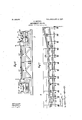
- Figure 1 is aside elevation ofa complete Aamusement device embodying the princi les of my inventionl as seen looking in the irection indicated by the arrow 1 in Fig. 2.
- Fig. 2 is a top lan view as seen looking in the direction in icated by the arrow 2 in Fig. 1.
- Fig. 3 is an enlarged detail of one of the tilting turn-tables and the means of operating the same, the parts being broken away to economize space.
- Fig. 4 is a view analogous toA Fig. 3, upon a larger scale, parts being omitted to more clearly show the other parts.
- Fig. 5 is a side elevation of the parts shown in Fig. 4 as seen looking in the direction indicated by the arrow 5 in Fig. 4.
- FIG. 6' is an enlarged cross-section substan- ⁇ tially on the lines 6 6 of Fig. 7. enlarged sectional elevation at the lower end of the chute and ⁇ taken substantially on lines 7 7 of Fig. 6.
- Fig. 8 is an enlarged cross-section on the line 8 8 of Fig. 1 and looking in the direction indicated by the arrow.
- 9 is an enlarged sectional elevation on the line 9 9 of Fig. 4 and looking inthe direction in'dicated by the arrow.
- Fig. 10 is a perspective of the rear end of one ofthe boats and showing the connection between the boat and the cable which runs the boat uphill.
- Fig.' 11 is an enlarged detail perspective of the dog shown on Fig.'A 10 removed from the boat.
- FIG. 12 is an enlarged detail perspective of the means of operating the turning-tables, Qthgrj par.ts,peingbroken away: "Fig 13 is an en arged detail perspective of the means of sto plng the turning-tables in alinement withlille' tracks.' Fig. 14 is a cross-section showing the friction driving mechanism whereby the turning-tables are started and stopped. Fig. 15 is a sectional detail.
- AMy mrproved amusement device is of the type known as shoot the chutes, my object being to economize space in the.
- con- Fig. 7 is an struction of such a device, to increase the speed of operation, and to improve the detailsof construction.
- the 6o platform 20 is mounted upon a suitable scaffolding 21.
- the inside tracks 22 and 23 lead from the platform 20Y to points below the water-leve 24, and the boats 25 coast down these tracks.
- the outer tracks 26 -and 27 lead from the water to the platform 20,'the lines followed by the outer tracks near their upper ends! being higher. than the inner tracks, as clearly shown in Fig.e 1.
- Endless chains 28 and 29 operate between the rails of the tracks 26 and 27 to form carriers to carry the boats from the water up the tracks 26 and 27 to the platform.
- the device yshown is a double-track mechvanism, there being two ⁇ tracks down andtwo tracks up, the tracks 22 and 26 forming one pair and tracks 23 and 27 forming the other pair.
- a turn-table 30' is mounted upon they pair of rails 37 and 38', mounted in a similar manner.
- the front side.of the platform 20, under the tracks 22 and 23, is lowered, ard notches 39 and 40 are cut in the tum-table, so that when the rails upon the turn-tablev are in alinement with the rails of track 23 said rails may tilt, as shown in Fig. 5, to bring the forward ends of therails vupon the turntable into inclined alinement with the ends of the rails of the track 23, so that the boat may slide down the track to the water.
- a timber 41 is located under eac turn-table anda bearingblock 42 is placed upon the timber.
- ivot 43 of the turn-table operates in the caring-block 42. mounted upon the timber 41 and upon other timbers'.
- a suitable frame hasarms radiati ing from the plivot 43, and wheels 46 are j ourn aled upon t e outer ends of these arms in position to travel upon 'the track 44.
- a Itrack 47 similar to track 44, is mounted upon the wheels 46, and the turn-table is built and supported upon the track 47 and upon the ivot 43, said turn-table consisting of suitab e framework 48, supporting the IOO
- a circular track 44 is l ITO ivot 35.
- the base .49 of this turn-table horizontally and vhaving a groove 50 in its periphery to receive the cable 51.
- the means of tilting the turn-table trackseach comprise a shaft 52, mounted v transversely of the tilting frame upon one side of the pivot 35; a similarshaft 53 upon the opposite side of the pivot; links 54 and 55, connected together and connected to the shaft 52 and connected to a bearing-plate 56 upon a rigid partof the frame to form a toggle-joint con- ⁇ nection between that end of the tilting frame and the rigid frame links 57 and 58, connected to the shaft 53 and connected together andl connected to bearing-blocks 59, secured to a rigid part of the frame, so as to form to gle-joint connections between that end of the tilting frame and the rigid frame; an oprerating-shaft 60, mounted upon the rigidl of the tilting frame; crank-arms 61, extending downwardly from the shaft 60 g connectingrods 62, connecting the lower ends of the crank-arms lto the central pivot of the links 54 and 55; connecting-ro'ds 63, connecting the lower ends of the crank-
- the means of operating the turn-tables comprise for each turntable a crank-shaft 65, mounted in bearings ⁇ 66; an eccentric 67, ixed upon the crank-shaft between the bearings; a sleeve 68, rotatably mounted upon the eccentric; a friction-wheel 69, fixed upon the sleeve; grooved drivingpulleys 70, fixed upon the sleeve; a drivingshaft 71, mounted parallel with the crankshaft a driving-pulley 72 upon the driving-shaft; the driving-belt 73 upon the pulleys; the friction drive-wheel 74 upon the shaft 71' in'position to be engaged by the friction-wheel 69; the shifting-lever 75, pivotally mounted; the connecting-'rod 76, connecting the lever 75 to the crank 77 upon the prank-shaft 65; the counter-shaft 78, and the pulleys 79 upon the counter-shaft, together with the cable 51, operating in the groove 50, running over the pulleys and
- the means for accomplishing this end comprise a plate 81, mounted u on the turntable and having a slot 82; the atcb-housing 83, mounted upon the frame; the latch 84, slidingly mounted in the housing in position to engage in the slot 82; the bell-crank lever 85 for pivotal y mounted, vand the connecting-rod 87, connecting the hand-lever to the bellcrank lever, Aso that when the hand-lever is moved in one direction the latch 84 will engage in the slot and stop the turn-table and so that when the lever is moved in the opposite direction the latch will be withdraw-n to 'release the turn-table.
- the levers 64 are mounted near the center of the turn-table, and a man is to be stationed at this point for operating these levers.
- the levers 75 and 86 are mounted upon the platform outside of the turn-table, as shown in Fig. 3, there being a pair of these levers for each turn-table, Aand a man is stationed in place to operate these levers, there being one man upon each side of the platform for this purpose.
- the mechanism is all driven from the motor 88.
- the chains 2 8 and 29 are operated in a guideway formed by the plates 89 and 90, so as to keep the chains from moving laterally.
- the means of connecting the boats to the chains is shown in detail in Figs.
- the tongs 104 may be carried by the operator into the boat and laid upon t e ⁇ platform convenient for the use of other operators. By the use of the, tongs it is not necessary that the boat be squarelyT over the cable. If the tongs were rigidly secured to the boat for the purpose of engaging the cable, i't would be necessary that the boat be brought accurately into line with the cable, whereas with the use ofthe disconnected tongs the cable maybe at either side of the boat or anywhere within reach of the operator.
- my improved' amusement device is as follows: Aseries of boats is placed upon the water 24, the ymachinery is started, the boats are floated into position between the guiderails 97 and 98 one at a time for each pair of tracks. The passengers onpatrons step into the boats, the boats are brought into position to be connected tothe chains, and the chains carry the boats up the inclined tracks 26 and 27. At the upper ends of these tracks the tilting platforms are in horizontal positions in alinement with the tracks and the boats are carried onto the platforms. Then van operator engages the handle 86 to release the turn-table, operates lthe lever 75 to rotate the turn-tables halff.
- an inclined track In an amusement device, an inclined track, a turn-table arranged for operation at the upper end of said track, a track arranged on the turn-table and adapted to' coincide with the inclined track, locking-plates fixed on the turn-table at right angles to the track thereon, a housing secured to the framework outside the turn-table, a locking-bolt operating through said housing and adapted to engage either one of the Alocking-plates, a bell-crank v having one end pivotally connected to the locking-bolt, arod pivotally connected at one -end to the opposite end ofthe bell-crank, and
Description
110. 849,970. .y PATENTED APR. 9, 1907.
Y P. BoYToN.
AMUSEMENT DEVICE.
APPLICATION FILED AUG. 27, 1904.
8 SHEETS-HEERE 3.
PATENTED APR. 9, 1907.
P. BOYTON. AMUSBMENT DEVICE.
.urmculon FILED 11110.27', 1-904.
EETS-SHBBT 4.
- PATBNTED APR. 9, 1907.
LBOYTON.
AMUSEMENT DEVICE.
APPLICATION FILED AUG. 27, 1904.
8 SHEETS-SHEET 6.
PATBNTED APR. 9, 1907.
` P.B0YT0N. AMUSEMENT DEVICE.
l APPLICATION FILED AUG.27, 1904.
@SHEETS-SHEET 6.
P. BOYTON. AMUSEMBNT DEVICE.'
APPLIOATION FILED AUG. 27, 1904.
s sums-SHEET a.
UNITED STATES PATENT oEEIeE.
l PAUL BOYTON, OF LOUIS, MISSOURI. l l
'AMus'EMl-:N'r pEvicE.
' lSpecification of Letters Patent.
Patented April 9, 1907.
Application filed August 27. 1904. Serial No. 222,441.
Toall whom, it may concern:
zen of the United States, and a resident of the city of St. Louis, State of Missouri; have invented'certain new and useful Improvements in Amusement Devices, of which the following is a specification containing a full,
` clear, and exact description, reference being vzo had yto the accompanying drawings, forming a part hereof.
My invention relates to improvements in amusement devices, and consists of the novel features herein 'shown and described and claimed. l
In the drawings, Figure 1 is aside elevation ofa complete Aamusement device embodying the princi les of my inventionl as seen looking in the irection indicated by the arrow 1 in Fig. 2. Fig. 2 is a top lan view as seen looking in the direction in icated by the arrow 2 in Fig. 1. Fig. 3 is an enlarged detail of one of the tilting turn-tables and the means of operating the same, the parts being broken away to economize space. Fig. 4 is a view analogous toA Fig. 3, upon a larger scale, parts being omitted to more clearly show the other parts. Fig. 5 is a side elevation of the parts shown in Fig. 4 as seen looking in the direction indicated by the arrow 5 in Fig. 4. Fig. 6'is an enlarged cross-section substan-` tially on the lines 6 6 of Fig. 7. enlarged sectional elevation at the lower end of the chute and `taken substantially on lines 7 7 of Fig. 6. Fig. 8 is an enlarged cross-section on the line 8 8 of Fig. 1 and looking in the direction indicated by the arrow. 9 is an enlarged sectional elevation on the line 9 9 of Fig. 4 and looking inthe direction in'dicated by the arrow. Fig. 10 is a perspective of the rear end of one ofthe boats and showing the connection between the boat and the cable which runs the boat uphill. Fig.' 11 is an enlarged detail perspective of the dog shown on Fig.'A 10 removed from the boat. Fig. 12 is an enlarged detail perspective of the means of operating the turning-tables, Qthgrj par.ts,peingbroken away: "Fig 13 is an en arged detail perspective of the means of sto plng the turning-tables in alinement withlille' tracks.' Fig. 14 is a cross-section showing the friction driving mechanism whereby the turning-tables are started and stopped. Fig. 15 is a sectional detail.
AMy mrproved amusement device is of the type known as shoot the chutes, my object being to economize space in the. con- Fig. 7 is an struction of such a device, to increase the speed of operation, and to improve the detailsof construction.
Referring tothe drawings in detail, the 6o platform 20 is mounted upon a suitable scaffolding 21. The inside tracks 22 and 23 lead from the platform 20Y to points below the water-leve 24, and the boats 25 coast down these tracks. The outer tracks 26 -and 27 lead from the water to the platform 20,'the lines followed by the outer tracks near their upper ends! being higher. than the inner tracks, as clearly shown in Fig.e 1. Endless chains 28 and 29 operate between the rails of the tracks 26 and 27 to form carriers to carry the boats from the water up the tracks 26 and 27 to the platform.
` The device yshown is a double-track mechvanism, there being two` tracks down andtwo tracks up, the tracks 22 and 26 forming one pair and tracks 23 and 27 forming the other pair. A turn-table 30'is mounted upon they pair of rails 37 and 38', mounted in a similar manner. The front side.of the platform 20, under the tracks 22 and 23, is lowered, ard notches 39 and 40 are cut in the tum-table, so that when the rails upon the turn-tablev are in alinement with the rails of track 23 said rails may tilt, as shown in Fig. 5, to bring the forward ends of therails vupon the turntable into inclined alinement with the ends of the rails of the track 23, so that the boat may slide down the track to the water. In constructing the latform 20 a timber 41 is located under eac turn-table anda bearingblock 42 is placed upon the timber. The
ivot 43 of the turn-table operates in the caring-block 42. mounted upon the timber 41 and upon other timbers'. A suitable frame hasarms radiati ing from the plivot 43, and wheels 46 are j ourn aled upon t e outer ends of these arms in position to travel upon 'the track 44. A Itrack 47, similar to track 44, is mounted upon the wheels 46, and the turn-table is built and supported upon the track 47 and upon the ivot 43, said turn-table consisting of suitab e framework 48, supporting the IOO A circular track 44 is l ITO ivot 35. The base .49 of this turn-table horizontally and vhaving a groove 50 in its periphery to receive the cable 51. The means of tilting the turn-table trackseach comprise a shaft 52, mounted v transversely of the tilting frame upon one side of the pivot 35; a similarshaft 53 upon the opposite side of the pivot; links 54 and 55, connected together and connected to the shaft 52 and connected to a bearing-plate 56 upon a rigid partof the frame to form a toggle-joint con- `nection between that end of the tilting frame and the rigid frame links 57 and 58, connected to the shaft 53 and connected together andl connected to bearing-blocks 59, secured to a rigid part of the frame, so as to form to gle-joint connections between that end of the tilting frame and the rigid frame; an oprerating-shaft 60, mounted upon the rigidl of the tilting frame; crank-arms 61, extending downwardly from the shaft 60 g connectingrods 62, connecting the lower ends of the crank-arms lto the central pivot of the links 54 and 55; connecting-ro'ds 63, connecting the lower ends of the crank-arms 61 tothe cen-` tral pivots of the links 57 and 58, and an o erating-lever 64 u on the outer end of tlllje shaft 60, so that w en the tilting frame is in a horizontal position the toggle-joint formed by the levers 57 and` 58 is straight and the toggle-joint formed by levers 54 and 55 is bent and so thatA when the toggle -joint formed by levers 54 and 55 is straight and the other toggle-joint bent the tilting frame is in an incline position and the tracks upon the frame are in incline alinement with the chute-tracks 22 or 23. The means of operating the turn-tables comprise for each turntable a crank-shaft 65, mounted in bearings `66; an eccentric 67, ixed upon the crank-shaft between the bearings; a sleeve 68, rotatably mounted upon the eccentric; a friction-wheel 69, fixed upon the sleeve; grooved drivingpulleys 70, fixed upon the sleeve; a drivingshaft 71, mounted parallel with the crankshaft a driving-pulley 72 upon the driving-shaft; the driving-belt 73 upon the pulleys; the friction drive-wheel 74 upon the shaft 71' in'position to be engaged by the friction-wheel 69; the shifting-lever 75, pivotally mounted; the connecting-'rod 76, connecting the lever 75 to the crank 77 upon the prank-shaft 65; the counter-shaft 78, and the pulleys 79 upon the counter-shaft, together with the cable 51, operating in the groove 50, running over the pulleys and 79 two or more times and over the guide-pulley 80, so that when the lever is operated in one directi'on the friction-wheel 69 Will beplaced.l
against the friction drive-wheel 74, thereby rotating the wheel 69, driving the pulleys 70, and moving the cable 51 and rotating the turn-table and so that when the lever is opame near the pivot 35 and transversely lerated in the opposite direction the frictionwheel will be disconnected and the turn-table stopped.
In order that the tracks upon the turntable may be brou ht into exact alinement with the chute-trac s, itis necessar to stop the turn-tables precisely in the rig t place, and the means for accomplishing this end comprise a plate 81, mounted u on the turntable and having a slot 82; the atcb-housing 83, mounted upon the frame; the latch 84, slidingly mounted in the housing in position to engage in the slot 82; the bell-crank lever 85 for pivotal y mounted, vand the connecting-rod 87, connecting the hand-lever to the bellcrank lever, Aso that when the hand-lever is moved in one direction the latch 84 will engage in the slot and stop the turn-table and so that when the lever is moved in the opposite direction the latch will be withdraw-n to 'release the turn-table. l
The levers 64 are mounted near the center of the turn-table, and a man is to be stationed at this point for operating these levers. The levers 75 and 86 are mounted upon the platform outside of the turn-table, as shown in Fig. 3, there being a pair of these levers for each turn-table, Aand a man is stationed in place to operate these levers, there being one man upon each side of the platform for this purpose. The mechanism is all driven from the motor 88. The chains 2 8 and 29 are operated in a guideway formed by the plates 89 and 90, so as to keep the chains from moving laterally. The means of connecting the boats to the chains is shown in detail in Figs. 10 and 11 and comprises an attaching-plate 91, secured to the rear end of the boat 25, the swinging plate 92, hinged to the attachingplate, and the dog 93, secured to the swinging plate 92 and extending below the bottom of t e boat, the lower end of said dog being bent backwardly to form a hook, so that when the boat floats into the path of the chain the dog will drop down between the side bars of the chain and hook under one of the cross-bars between the side bars 94 and 95 and hook under one of the cross-bars 96, so that as the chain moves up the incline the boat will be carried upon the track. At the lower ends of the tracks 26 and 27 there are I l I guide- rails 97 and 98 to guidethe boatgintop.
position to be engaged by the "chain, framework supporting thetracks an is shown in Figs. 6 and 7. -v
The
olperating the latch; the hand-lever 86, I
IIO
When the boat standing -cornparatively` .93 connects the chain While the boat is in motion, thereby reducing the shock to the occupants of the boat. 'The tongs 104 may be carried by the operator into the boat and laid upon t e` platform convenient for the use of other operators. By the use of the, tongs it is not necessary that the boat be squarelyT over the cable. If the tongs were rigidly secured to the boat for the purpose of engaging the cable, i't would be necessary that the boat be brought accurately into line with the cable, whereas with the use ofthe disconnected tongs the cable maybe at either side of the boat or anywhere within reach of the operator.
The details of construction may be Widely varied, as it is only necessary to have the movin" cable and a pair of tongs for gripping the cable, so as to start the boat toward 0r up the incline before it is connected to the chain. v
The operation of my improved' amusement device is as follows: Aseries of boats is placed upon the water 24, the ymachinery is started, the boats are floated into position between the guiderails 97 and 98 one at a time for each pair of tracks. The passengers onpatrons step into the boats, the boats are brought into position to be connected tothe chains, and the chains carry the boats up the inclined tracks 26 and 27. At the upper ends of these tracks the tilting platforms are in horizontal positions in alinement with the tracks and the boats are carried onto the platforms. Then van operator engages the handle 86 to release the turn-table, operates lthe lever 75 to rotate the turn-tables halff.
Way around, thus bringing the boat intoaline--v ment with the chute-tracks. The operation upon the turn-table operates the lever,l tilts the frame, and the'boat descends the chutetrack, and this operation goes on in rapid succession. By the use of the turn-tables and 'the tilting frames it is possible toturn the boat and start it down the incline in a great deal less space and a great deal less time than hasv been accomplished by any of the old conv structions I call special attentionto the fact that I take on the passengers at the lower ends of the incline and that the passengers are carried rapidly up the incline, quickly turned and shot down, and that with the exception i of the operators necessary and the machinery necessary there is nothing upon the platform 20-all of the patrons going and coming and Waiting are upon the ground at the lower ends of the incline. This is a matter of great. importance in economy of space and in safety of operation. y
-I claim- In an amusement device, an inclined track, a turn-table arranged for operation at the upper end of said track, a track arranged on the turn-table and adapted to' coincide with the inclined track, locking-plates fixed on the turn-table at right angles to the track thereon, a housing secured to the framework outside the turn-table, a locking-bolt operating through said housing and adapted to engage either one of the Alocking-plates, a bell-crank v having one end pivotally connected to the locking-bolt, arod pivotally connected at one -end to the opposite end ofthe bell-crank, and
ALFRED A. EIoKs, M. M. BRAZIL'L, I
Priority Applications (1)
| Application Number | Priority Date | Filing Date | Title |
|---|---|---|---|
| US22244104A US849970A (en) | 1904-08-27 | 1904-08-27 | Amusement device. |
Applications Claiming Priority (1)
| Application Number | Priority Date | Filing Date | Title |
|---|---|---|---|
| US22244104A US849970A (en) | 1904-08-27 | 1904-08-27 | Amusement device. |
Publications (1)
| Publication Number | Publication Date |
|---|---|
| US849970A true US849970A (en) | 1907-04-09 |
Family
ID=2918431
Family Applications (1)
| Application Number | Title | Priority Date | Filing Date |
|---|---|---|---|
| US22244104A Expired - Lifetime US849970A (en) | 1904-08-27 | 1904-08-27 | Amusement device. |
Country Status (1)
| Country | Link |
|---|---|
| US (1) | US849970A (en) |
Cited By (24)
| Publication number | Priority date | Publication date | Assignee | Title |
|---|---|---|---|---|
| US4326624A (en) * | 1977-09-14 | 1982-04-27 | Werkzeugmaschinenfabrik Oerlikon-Buhrle Ag | Pallet feeder |
| US5732635A (en) * | 1996-06-11 | 1998-03-31 | Mckoy; Errol W. | Amusement power-cable-propelled and channel-guided boat ride structure |
| US5860364A (en) * | 1996-06-11 | 1999-01-19 | Mckoy; Errol W. | Amusement boat ride featuring linear induction motor drive integrated with guide channel structure |
| US6237499B1 (en) | 1996-06-11 | 2001-05-29 | Mckoy Errol W. | Watercraft amusement ride |
| EP1171209A1 (en) * | 1999-04-21 | 2002-01-16 | Universal City Studios, Inc. | Roller coaster control system |
| US20020082097A1 (en) * | 2000-09-11 | 2002-06-27 | Henry Jeffrey W. | Water amusement system and method |
| US20050090322A1 (en) * | 2003-10-24 | 2005-04-28 | Henry, Schooley & Associates, L.L.C. | Method and system of participant identifiers for water amusement parks |
| US20060111196A1 (en) * | 2004-11-24 | 2006-05-25 | Henry Jeffery W | Rollable carrier ride |
| US20060111195A1 (en) * | 2004-11-24 | 2006-05-25 | Henry Jeffery W | Water amusement park conveyors |
| US20070033867A1 (en) * | 2005-04-20 | 2007-02-15 | Henry Jeffery W | Composite tree |
| US20070049385A1 (en) * | 2005-08-30 | 2007-03-01 | Henry Jeffery W | Water amusement park conveyor barriers |
| US20070049387A1 (en) * | 2005-08-03 | 2007-03-01 | Henry Jeffery W | Water amusement park water channel flow system |
| US20070049386A1 (en) * | 2005-08-30 | 2007-03-01 | Henry Jeffery W | Adjusting participant flow rate in water amusement parks |
| US20070060402A1 (en) * | 2005-08-30 | 2007-03-15 | Henry Jeffery W | Modular water amusement park conveyors |
| US20070060403A1 (en) * | 2005-08-30 | 2007-03-15 | Henry Jeffery W | Water amusement park conveyors |
| US20070087851A1 (en) * | 2005-09-02 | 2007-04-19 | Henry Jeffery W | Water amusement system and method including a self-contained floating marine park |
| US20070087850A1 (en) * | 2005-09-02 | 2007-04-19 | Henry Jeffery W | Amusement water rides involving interactive user environments |
| US20070219004A1 (en) * | 2006-03-14 | 2007-09-20 | Henry Jeffery W | Method and system of positionable covers for water amusement parks |
| US7762899B2 (en) | 2005-08-30 | 2010-07-27 | Water Ride Concepts, Inc. | Water amusement park conveyor support elements |
| US7775895B2 (en) | 2005-08-03 | 2010-08-17 | Water Ride Concepts, Inc. | Water amusement park water channel and adjustable flow controller |
| US7857704B2 (en) | 2005-09-15 | 2010-12-28 | Water Ride Concepts, Inc. | Amusement water rides involving games of chance |
| US8079916B2 (en) | 2008-12-18 | 2011-12-20 | Water Ride Concepts, Inc. | Themed amusement river ride system |
| US8096892B2 (en) | 2002-03-25 | 2012-01-17 | Water Ride Concepts, Inc. | Control system for water amusement devices |
| US8210954B2 (en) | 2005-09-02 | 2012-07-03 | Water Ride Concepts, Inc. | Amusement water rides involving exercise circuits |
-
1904
- 1904-08-27 US US22244104A patent/US849970A/en not_active Expired - Lifetime
Cited By (69)
| Publication number | Priority date | Publication date | Assignee | Title |
|---|---|---|---|---|
| US4326624A (en) * | 1977-09-14 | 1982-04-27 | Werkzeugmaschinenfabrik Oerlikon-Buhrle Ag | Pallet feeder |
| US20040065223A1 (en) * | 1996-06-11 | 2004-04-08 | Mckoy Errol W. | Watercraft amusement ride |
| US5732635A (en) * | 1996-06-11 | 1998-03-31 | Mckoy; Errol W. | Amusement power-cable-propelled and channel-guided boat ride structure |
| US5860364A (en) * | 1996-06-11 | 1999-01-19 | Mckoy; Errol W. | Amusement boat ride featuring linear induction motor drive integrated with guide channel structure |
| DE19803465A1 (en) * | 1996-06-11 | 1999-08-12 | Errol W Mckoy | Amusement power cable propelled and channel guided boat ride structure |
| DE19803465C2 (en) * | 1996-06-11 | 2001-01-25 | Errol W Mckoy | Pleasure boat facility |
| US6237499B1 (en) | 1996-06-11 | 2001-05-29 | Mckoy Errol W. | Watercraft amusement ride |
| US6354223B2 (en) | 1996-06-11 | 2002-03-12 | Mckoy Errol W. | Watercraft amusement ride |
| US6860209B2 (en) | 1996-06-11 | 2005-03-01 | Mckoy Errol W. | Watercraft amusement ride |
| US6629501B2 (en) * | 1996-06-11 | 2003-10-07 | Mckoy Errol W. | Watercraft amusement ride |
| EP1171209A1 (en) * | 1999-04-21 | 2002-01-16 | Universal City Studios, Inc. | Roller coaster control system |
| EP1171209A4 (en) * | 1999-04-21 | 2004-04-28 | Universal City Studios Inc | Roller coaster control system |
| US7740542B2 (en) | 2000-09-11 | 2010-06-22 | Water Ride Concepts, Inc. | Water amusement method |
| US20020082097A1 (en) * | 2000-09-11 | 2002-06-27 | Henry Jeffrey W. | Water amusement system and method |
| US7285053B2 (en) | 2000-09-11 | 2007-10-23 | Nbgs International, Inc. | Water amusement system and method |
| US20050090320A1 (en) * | 2000-09-11 | 2005-04-28 | Nbgs International, Inc | Water amusement method |
| US20050090321A1 (en) * | 2000-09-11 | 2005-04-28 | Nbgs International, Inc. | Conveyor control system and method for water amusement parks |
| US7371182B2 (en) | 2000-09-11 | 2008-05-13 | Nbgs International, Inc. | Conveyor control system and method for water amusement parks |
| US20050085306A1 (en) * | 2000-09-11 | 2005-04-21 | Nbgs International, Inc | Conveyor system and method for water amusement parks |
| US8197352B2 (en) | 2000-09-11 | 2012-06-12 | Water Ride Concepts, Inc. | Methods and systems for amusement park conveyor belt systems |
| US8070615B2 (en) | 2000-09-11 | 2011-12-06 | Water Ride Concepts, Inc. | Methods and systems for water amusement conveyor |
| US7491128B2 (en) | 2000-09-11 | 2009-02-17 | Nbgs International, Inc. | Conveyor system and method for water amusement parks |
| US8096892B2 (en) | 2002-03-25 | 2012-01-17 | Water Ride Concepts, Inc. | Control system for water amusement devices |
| US8075413B2 (en) | 2003-10-24 | 2011-12-13 | Water Ride Concepts, Inc. | Continuous water ride method and system for water amusement parks |
| US7775894B2 (en) | 2003-10-24 | 2010-08-17 | Water Ride Concepts, Inc. | Method and system of participant identifiers for water amusement parks |
| US7229359B2 (en) | 2003-10-24 | 2007-06-12 | Henry, Schooley & Associates, L.L.C. | Continuous water ride |
| US20050090322A1 (en) * | 2003-10-24 | 2005-04-28 | Henry, Schooley & Associates, L.L.C. | Method and system of participant identifiers for water amusement parks |
| US20060111196A1 (en) * | 2004-11-24 | 2006-05-25 | Henry Jeffery W | Rollable carrier ride |
| US7497784B2 (en) | 2004-11-24 | 2009-03-03 | Water Ride Concepts, Inc. | Rollable carrier ride |
| US7942752B2 (en) | 2004-11-24 | 2011-05-17 | Water Ride Concepts, Inc. | Water amusement park multiple path conveyors |
| US20060111195A1 (en) * | 2004-11-24 | 2006-05-25 | Henry Jeffery W | Water amusement park conveyors |
| US8162769B2 (en) | 2004-11-24 | 2012-04-24 | Water Ride Concepts, Inc. | Water amusement park conveyor roller belts |
| US20060142090A1 (en) * | 2004-11-24 | 2006-06-29 | Henry, Schooley & Associates, L.L.C. | Water amusement park multiple path conveyors |
| US20060135274A1 (en) * | 2004-11-24 | 2006-06-22 | Henry, Schooley & Associates, L.L.C. | Water amusement park conveyor roller belts |
| US7597630B2 (en) | 2004-11-24 | 2009-10-06 | Water Ride Concepts, Inc. | Water amusement park conveyors |
| US20070033866A1 (en) * | 2005-04-20 | 2007-02-15 | Henry Jeffery W | Lift apparatus for base-mounted plant |
| US20070051037A1 (en) * | 2005-04-20 | 2007-03-08 | Henry Jeffery W | Thematic tree system |
| US7785207B2 (en) | 2005-04-20 | 2010-08-31 | Water Ride Concepts, Inc. | Water amusement system with elevated structure |
| US7921601B2 (en) | 2005-04-20 | 2011-04-12 | Water Ride Concepts, Inc. | Water amusement system with trees |
| US20070033867A1 (en) * | 2005-04-20 | 2007-02-15 | Henry Jeffery W | Composite tree |
| US20070049387A1 (en) * | 2005-08-03 | 2007-03-01 | Henry Jeffery W | Water amusement park water channel flow system |
| US7727077B2 (en) | 2005-08-03 | 2010-06-01 | Water Ride Concepts, Inc. | Water amusement park water channel flow system |
| US7775895B2 (en) | 2005-08-03 | 2010-08-17 | Water Ride Concepts, Inc. | Water amusement park water channel and adjustable flow controller |
| US20070049385A1 (en) * | 2005-08-30 | 2007-03-01 | Henry Jeffery W | Water amusement park conveyor barriers |
| US20070060402A1 (en) * | 2005-08-30 | 2007-03-15 | Henry Jeffery W | Modular water amusement park conveyors |
| US8282497B2 (en) | 2005-08-30 | 2012-10-09 | Water Ride Concepts, Inc. | Modular water amusement park conveyors |
| US7371183B2 (en) | 2005-08-30 | 2008-05-13 | Henry, Schooley & Associates, L.L.C. | Water amusement park conveyors |
| US20070049386A1 (en) * | 2005-08-30 | 2007-03-01 | Henry Jeffery W | Adjusting participant flow rate in water amusement parks |
| US20070060403A1 (en) * | 2005-08-30 | 2007-03-15 | Henry Jeffery W | Water amusement park conveyors |
| US7762899B2 (en) | 2005-08-30 | 2010-07-27 | Water Ride Concepts, Inc. | Water amusement park conveyor support elements |
| US7815514B2 (en) | 2005-08-30 | 2010-10-19 | Water Ride Concepts, Inc. | Water amusement park conveyor barriers |
| US7775896B2 (en) | 2005-09-02 | 2010-08-17 | Water Ride Concepts, Inc. | Methods and systems for self-contained floating marine parks |
| US7758435B2 (en) | 2005-09-02 | 2010-07-20 | Water Ride Concepts, Inc. | Amusement water rides involving interactive user environments |
| US7828667B2 (en) | 2005-09-02 | 2010-11-09 | Water Ride Concepts, Inc. | Methods and systems for active filtration of portions of self-contained floating marine parks |
| US8663023B2 (en) | 2005-09-02 | 2014-03-04 | Water Ride Concepts, Inc. | Methods and systems for viewing marine life from self-contained floating marine parks |
| US20070087851A1 (en) * | 2005-09-02 | 2007-04-19 | Henry Jeffery W | Water amusement system and method including a self-contained floating marine park |
| US7780536B2 (en) | 2005-09-02 | 2010-08-24 | Water Ride Concepts, Inc. | Methods and systems for positionable screen for self-contained floating marine parks |
| US7766753B2 (en) | 2005-09-02 | 2010-08-03 | Water Ride Concepts, Inc. | Methods and systems for modular self-contained floating marine parks |
| US20110118039A1 (en) * | 2005-09-02 | 2011-05-19 | Water Ride Concepts, Inc. | Methods and systems for viewing marine life from self-contained floating marine parks |
| US8210954B2 (en) | 2005-09-02 | 2012-07-03 | Water Ride Concepts, Inc. | Amusement water rides involving exercise circuits |
| US7811177B2 (en) | 2005-09-02 | 2010-10-12 | Water Ride Concepts, Inc. | Water amusement system and method including a self-contained floating marine park |
| US20070087853A1 (en) * | 2005-09-02 | 2007-04-19 | Henry Jeffery W | Methods and systems for active filtration of portions of self-contained floating marine parks |
| US20070087850A1 (en) * | 2005-09-02 | 2007-04-19 | Henry Jeffery W | Amusement water rides involving interactive user environments |
| US7857704B2 (en) | 2005-09-15 | 2010-12-28 | Water Ride Concepts, Inc. | Amusement water rides involving games of chance |
| US20070219004A1 (en) * | 2006-03-14 | 2007-09-20 | Henry Jeffery W | Method and system of positionable covers for water amusement parks |
| US7762900B2 (en) | 2006-03-14 | 2010-07-27 | Water Ride Concepts, Inc. | Method and system of positionable covers for water amusement parks |
| US8251832B2 (en) | 2006-03-14 | 2012-08-28 | Water Ride Concepts, Inc. | Method and system of positionable covers for water amusement parks |
| US20110014988A1 (en) * | 2006-03-14 | 2011-01-20 | Water Ride Concepts, Inc. | Method and system of positionable covers for water amusement parks |
| US8079916B2 (en) | 2008-12-18 | 2011-12-20 | Water Ride Concepts, Inc. | Themed amusement river ride system |
Similar Documents
| Publication | Publication Date | Title |
|---|---|---|
| US849970A (en) | Amusement device. | |
| US1440661A (en) | Amusement device | |
| US540715A (en) | Coasting apparatus | |
| US854626A (en) | Excavator. | |
| US374442A (en) | Peters | |
| US375293A (en) | Passenger-elevator | |
| US409098A (en) | Store-service apparatus | |
| US983301A (en) | Freight-transhipping apparatus. | |
| US793471A (en) | Amusement device. | |
| US1108048A (en) | Log-manipulating mechanism. | |
| US857188A (en) | Log-loader. | |
| US381032A (en) | Half to john h | |
| US357234A (en) | Lifting apparatus | |
| US321348A (en) | Lumber-filer | |
| US1491307A (en) | Amusement apparatus | |
| US852184A (en) | Pleasure-railway. | |
| US719012A (en) | Log-loader. | |
| US394727A (en) | scully | |
| US482469A (en) | Transportation system | |
| US586699A (en) | sodebberg | |
| US408692A (en) | Grip aid | |
| US404996A (en) | Track-laying machine | |
| US353922A (en) | Portable rail-saw plant | |
| US955217A (en) | Inclined railway. | |
| US868016A (en) | Means or apparatus for the formation of spoil heaps, banks, &c. |