US8347628B2 - Power generation directly from compressed air for exploiting wind and solar power - Google Patents
Power generation directly from compressed air for exploiting wind and solar power Download PDFInfo
- Publication number
- US8347628B2 US8347628B2 US12/800,671 US80067110A US8347628B2 US 8347628 B2 US8347628 B2 US 8347628B2 US 80067110 A US80067110 A US 80067110A US 8347628 B2 US8347628 B2 US 8347628B2
- Authority
- US
- United States
- Prior art keywords
- air
- stage
- pressure
- energy
- compressed air
- Prior art date
- Legal status (The legal status is an assumption and is not a legal conclusion. Google has not performed a legal analysis and makes no representation as to the accuracy of the status listed.)
- Active, expires
Links
Images


Classifications
-
- F—MECHANICAL ENGINEERING; LIGHTING; HEATING; WEAPONS; BLASTING
- F02—COMBUSTION ENGINES; HOT-GAS OR COMBUSTION-PRODUCT ENGINE PLANTS
- F02C—GAS-TURBINE PLANTS; AIR INTAKES FOR JET-PROPULSION PLANTS; CONTROLLING FUEL SUPPLY IN AIR-BREATHING JET-PROPULSION PLANTS
- F02C1/00—Gas-turbine plants characterised by the use of hot gases or unheated pressurised gases, as the working fluid
- F02C1/02—Gas-turbine plants characterised by the use of hot gases or unheated pressurised gases, as the working fluid the working fluid being an unheated pressurised gas
-
- F—MECHANICAL ENGINEERING; LIGHTING; HEATING; WEAPONS; BLASTING
- F02—COMBUSTION ENGINES; HOT-GAS OR COMBUSTION-PRODUCT ENGINE PLANTS
- F02C—GAS-TURBINE PLANTS; AIR INTAKES FOR JET-PROPULSION PLANTS; CONTROLLING FUEL SUPPLY IN AIR-BREATHING JET-PROPULSION PLANTS
- F02C6/00—Plural gas-turbine plants; Combinations of gas-turbine plants with other apparatus; Adaptations of gas- turbine plants for special use
- F02C6/14—Gas-turbine plants having means for storing energy, e.g. for meeting peak loads
- F02C6/16—Gas-turbine plants having means for storing energy, e.g. for meeting peak loads for storing compressed air
-
- F—MECHANICAL ENGINEERING; LIGHTING; HEATING; WEAPONS; BLASTING
- F03—MACHINES OR ENGINES FOR LIQUIDS; WIND, SPRING, OR WEIGHT MOTORS; PRODUCING MECHANICAL POWER OR A REACTIVE PROPULSIVE THRUST, NOT OTHERWISE PROVIDED FOR
- F03D—WIND MOTORS
- F03D9/00—Adaptations of wind motors for special use; Combinations of wind motors with apparatus driven thereby; Wind motors specially adapted for installation in particular locations
- F03D9/10—Combinations of wind motors with apparatus storing energy
- F03D9/17—Combinations of wind motors with apparatus storing energy storing energy in pressurised fluids
-
- F—MECHANICAL ENGINEERING; LIGHTING; HEATING; WEAPONS; BLASTING
- F03—MACHINES OR ENGINES FOR LIQUIDS; WIND, SPRING, OR WEIGHT MOTORS; PRODUCING MECHANICAL POWER OR A REACTIVE PROPULSIVE THRUST, NOT OTHERWISE PROVIDED FOR
- F03G—SPRING, WEIGHT, INERTIA OR LIKE MOTORS; MECHANICAL-POWER PRODUCING DEVICES OR MECHANISMS, NOT OTHERWISE PROVIDED FOR OR USING ENERGY SOURCES NOT OTHERWISE PROVIDED FOR
- F03G6/00—Devices for producing mechanical power from solar energy
- F03G6/02—Devices for producing mechanical power from solar energy using a single state working fluid
- F03G6/04—Devices for producing mechanical power from solar energy using a single state working fluid gaseous
-
- Y—GENERAL TAGGING OF NEW TECHNOLOGICAL DEVELOPMENTS; GENERAL TAGGING OF CROSS-SECTIONAL TECHNOLOGIES SPANNING OVER SEVERAL SECTIONS OF THE IPC; TECHNICAL SUBJECTS COVERED BY FORMER USPC CROSS-REFERENCE ART COLLECTIONS [XRACs] AND DIGESTS
- Y02—TECHNOLOGIES OR APPLICATIONS FOR MITIGATION OR ADAPTATION AGAINST CLIMATE CHANGE
- Y02E—REDUCTION OF GREENHOUSE GAS [GHG] EMISSIONS, RELATED TO ENERGY GENERATION, TRANSMISSION OR DISTRIBUTION
- Y02E10/00—Energy generation through renewable energy sources
- Y02E10/40—Solar thermal energy, e.g. solar towers
- Y02E10/46—Conversion of thermal power into mechanical power, e.g. Rankine, Stirling or solar thermal engines
-
- Y—GENERAL TAGGING OF NEW TECHNOLOGICAL DEVELOPMENTS; GENERAL TAGGING OF CROSS-SECTIONAL TECHNOLOGIES SPANNING OVER SEVERAL SECTIONS OF THE IPC; TECHNICAL SUBJECTS COVERED BY FORMER USPC CROSS-REFERENCE ART COLLECTIONS [XRACs] AND DIGESTS
- Y02—TECHNOLOGIES OR APPLICATIONS FOR MITIGATION OR ADAPTATION AGAINST CLIMATE CHANGE
- Y02E—REDUCTION OF GREENHOUSE GAS [GHG] EMISSIONS, RELATED TO ENERGY GENERATION, TRANSMISSION OR DISTRIBUTION
- Y02E10/00—Energy generation through renewable energy sources
- Y02E10/70—Wind energy
- Y02E10/72—Wind turbines with rotation axis in wind direction
-
- Y—GENERAL TAGGING OF NEW TECHNOLOGICAL DEVELOPMENTS; GENERAL TAGGING OF CROSS-SECTIONAL TECHNOLOGIES SPANNING OVER SEVERAL SECTIONS OF THE IPC; TECHNICAL SUBJECTS COVERED BY FORMER USPC CROSS-REFERENCE ART COLLECTIONS [XRACs] AND DIGESTS
- Y02—TECHNOLOGIES OR APPLICATIONS FOR MITIGATION OR ADAPTATION AGAINST CLIMATE CHANGE
- Y02E—REDUCTION OF GREENHOUSE GAS [GHG] EMISSIONS, RELATED TO ENERGY GENERATION, TRANSMISSION OR DISTRIBUTION
- Y02E60/00—Enabling technologies; Technologies with a potential or indirect contribution to GHG emissions mitigation
- Y02E60/16—Mechanical energy storage, e.g. flywheels or pressurised fluids
-
- Y—GENERAL TAGGING OF NEW TECHNOLOGICAL DEVELOPMENTS; GENERAL TAGGING OF CROSS-SECTIONAL TECHNOLOGIES SPANNING OVER SEVERAL SECTIONS OF THE IPC; TECHNICAL SUBJECTS COVERED BY FORMER USPC CROSS-REFERENCE ART COLLECTIONS [XRACs] AND DIGESTS
- Y02—TECHNOLOGIES OR APPLICATIONS FOR MITIGATION OR ADAPTATION AGAINST CLIMATE CHANGE
- Y02E—REDUCTION OF GREENHOUSE GAS [GHG] EMISSIONS, RELATED TO ENERGY GENERATION, TRANSMISSION OR DISTRIBUTION
- Y02E70/00—Other energy conversion or management systems reducing GHG emissions
- Y02E70/30—Systems combining energy storage with energy generation of non-fossil origin
-
- Y—GENERAL TAGGING OF NEW TECHNOLOGICAL DEVELOPMENTS; GENERAL TAGGING OF CROSS-SECTIONAL TECHNOLOGIES SPANNING OVER SEVERAL SECTIONS OF THE IPC; TECHNICAL SUBJECTS COVERED BY FORMER USPC CROSS-REFERENCE ART COLLECTIONS [XRACs] AND DIGESTS
- Y02—TECHNOLOGIES OR APPLICATIONS FOR MITIGATION OR ADAPTATION AGAINST CLIMATE CHANGE
- Y02T—CLIMATE CHANGE MITIGATION TECHNOLOGIES RELATED TO TRANSPORTATION
- Y02T50/00—Aeronautics or air transport
- Y02T50/60—Efficient propulsion technologies, e.g. for aircraft
Definitions
- the present invention relates to a novel machine (the Compressed Air Turbine-Generator, or CAT-G) to manage energy gathered from renewable sources, such as solar and wind power.
- Compressed Air Energy Storage (C.A.E.S.) is a promising mode of clean energy storage.
- a major challenge facing this technology is the need to efficiently convert the compressed air energy into electricity.
- the high-pressure air is used only to improve the efficiency of a conventional jet-powered turbine generator.
- the focus herein is on a new technology that efficiently converts the energy stored in compressed air directly into electrical power without producing greenhouse byproduct gases or other pollutants. This new capability will add important flexibility to the optimization of ecologically friendly energy systems.
- FIG. 1 shows a practical system that is based on the compression of air and the storage of energy (in a “Heat” and a “Pressure” Reservoir) at ambient atmospheric temperature, T O . It illustrates that wind power can be used to compress air (from the atmosphere) so that high pressure air goes into a ‘C.A.E.S. Energy Storage Reservoir’ and the energy from the constant temperature (Isothermal) air compression flows (as heat) into a Water (Heat) Reservoir. (Heating the water in this tank does raise its temperature slightly so that, in general, T WATER ⁇ T O ; but this elevation in temperature is not critical to the storage-recovery process).
- An obvious advantage of this configuration is that the energy stored at T O is not lost by dissipation to the environment. Any energy reservoir that is hotter than T O must lose energy to colder regions by convection, conduction and radiation. With the energy reservoirs held at, or near T O , thermal convection, conduction and solar heating helps stabilize the energy reservoirs, as energy (via heat-flow) is consumed in the recovery part of the storage-recovery process.
- a vital element of this scheme is a means for recovering the stored energy from the reservoirs and delivering it in a useful form.
- the focus herein is on the design and operation of the CAT-G, it is important to remember that the behavior of the energy reservoirs (including the Earth's atmosphere) at T ⁇ T O must be understood as critical parts of the storage and recovery system.
- the invention described herein is an axial turbine system that functions in the manner of a cascaded set of shrouded windmills, often called a ducted fan system.
- the blades of the turbine stages act as the blades of windmills.
- turbine rotation extracts mechanical energy and also reduces the pressure of the expended air.
- the mechanical energy extracted by the turbine stage is converted to electrical energy in a convenient manner.
- the airstream cannot deflect around the rotating blades as in a conventional windmill. It must flow through the blades and along the axis of the system.
- the airstream having given up some energy to the 1 st stage of rotating blades, exhibits a pressure drop and an increase in volume. Absent a source of heating within the CAT-G, there would typically also be a reduction in temperature that is both significant and progressive.
- the overall design challenge is to optimize the air flow, the heat exchange, the blade size, shape and rotation speed to maximize the overall efficiency of energy recovery.
- the turbine stages cause the air pressure to be stepped down, stage by stage, from the high entry pressure to atmospheric pressure at the outlet.
- heat is supplied from an ambient temperature reservoir. This increases the air pressure and temperature as necessary for efficient energy recovery.
- the addition of heat is vital for energy recovery in the CAT-G.
- maintaining the compressed air at (or near) T O at certain points in the CAT-G is a critical design element that is discussed in detail below.
- the principal design goal of the CAT-G is to achieve high efficiency for energy recovery from stored compressed air and heat, converted into electricity.
- the CAT-G is used in conjunction with a system based on the second kind of compression process, called Isothermal.
- Isothermal a system based on the second kind of compression process
- the air compressor in FIG. 1 is cooled by water from the Water (Heat) Reservoir, where energy from isothermal compression is retained, (slightly) raising the temperature of the large volume of water within this reservoir. To be most effective, this reservoir must readily exchange heat with its ambient environment (e.g., the atmosphere). It therefore cannot retain the added heat from the compression of air for any long time. Even if some of the stored energy from isothermal compression was dissipated (and this reservoir was to cool back to T O ), sufficient energy remains to provide the necessary heating inside the CAT-G.
- an important design principle is that the air flow through the CAT-G must approximate a constant temperature (isothermal) process. This is because isothermal compression followed by isothermal expansion back along the same path would ideally permit complete (100% efficient) energy recovery. In pursuing this goal, it is important to avoid the numerous factors (including heat loss from the system) that can prevent recovery of some stored energy.
- the design goal of the CAT-G is to duplicate (but in the reverse direction) the constant temperature process by which air was initially compressed into the storage reservoir. Therefore, an important requirement is that energy must be converted to electricity without changing the air temperature at the entrance of each CAT-G stage.
- the air reservoir would contain sufficient energy that an expansion sequence based only on adiabatic expansions of air could result in energy recovery with an exhaust that is at (P O ,T O ).
- Using high temperature reservoirs is, however, an impractical approach for long-term storage because such reservoirs necessarily dissipate heat by convection, conduction and radiation losses to the cooler environment. This lost energy cannot be returned to a high temperature heat reservoir without additional work. The heat loss is thus an irreversible process.
- the complexity of providing loss-less heat storage transforms into one of providing a means to effectively supply energy, by means of heat flow (from a T O reservoir), to the air flow between the CAT-G rotors.
- This required energy is supplied from the same reservoir that was used to absorb the heat from isothermal air compression (i.e., it is essentially gleaned from the atmosphere); and, such heat addition must be included to establish a (quasi) inverse to the isothermal compression process.
- TSR ⁇ R/v, where ⁇ is the speed of rotation (radians/s) and v is the air flow rate (the free-stream-velocity of the wind).
- FIG. 3 shows the relationship between TSR and c p ; a principal element in the design of the CAT-G rotors.
- FIG. 3 corresponds to an unshrouded rotor.
- Total efficiency can be estimated (in the ideal case of no losses due to turbulence, friction, etc.) for a 6-stage CAT-G having each stage designed to extract 40% of the energy from the airstream. If each stage passes 60% of the input energy (and extracts 40%), the relative outlet energy will be only 0.6 to the power 6 (about 0.047) implying that the sum of the extracted energy is about 0.953, i.e. 95.3% efficiency!
- this simple approximation does not account well, quantitatively, for the thermodynamic work of adiabatic expansion in the rotors combined with heat replacement. Although all the energy stored during compression cannot be recovered, the ideal thermodynamic efficiency, ⁇ , is still respectably high.
- the turbine stages cause the air pressure to be stepped down, stage by stage, from the high entry pressure to atmospheric pressure at the outlet.
- heat is supplied from a water (heat) reservoir at ambient temperature. This increases the air pressure and temperature is necessary for efficient energy recovery. The additional heat is vital for achieving high CAT-G recovery efficiency.
- maintaining the compressed air at (or near) T O at certain points in the CAT-G is a critical design element that is discussed in detail below.
- the CAT-G operates as follows:
- Compressed Air in the C.A.E.S. reservoir acts like a compressed spring that releases some energy (from the internal energy of the air) to the 1 st rotor.
- the pressure head in this reservoir pushes the air along the CAT-G axis, through a compression section, containing heat exchangers, where energy from the “Heat Reservoir” reloads the spring by restoring the air to ambient temperature.
- the principal benefit of the CAT-G comes from its compatibility with ambient temperature energy reservoirs. This is the basis for its capability to provide electrical power on a 24/7 basis (i.e., after an indefinite storage time) without consuming fossil fuel or producing any greenhouse gas byproducts, whatsoever.
- excess power that which is not sent to a grid for immediate use
- air pumps and establish an energy reserve by forcing compressed air into air-tight storage chambers (e.g., subterranean caverns from depleted pools of oil or gas); and heat into the large heat reservoir (which can then be allowed to cool back to ambient temperature).
- the CAT-G is the critical element for efficiently converting the stored energy (C.A.E.S. and stored heat) directly into electricity. Because CAT-G operation does not require high temperatures, velocities or stresses, the equipment can be both low cost and durable.
- C.A.E.S. technology also benefits from the fact that compressed air (and the energy it carries) can be transported long distances simply via pipelines. It may prove beneficial to move compressed air in this manner from the renewable energy fields to distant points of storage and/or use. Local reservoirs of ambient temperature water can be readily provided and kept warm by atmospheric and solar heating. It may even prove effective, by the use of pipeline networks, to distribute high pressure air from many wide-spread regions of collection. This could prove beneficial for stabilizing wind-power reserves and for providing stored energy buffers close to the CAT-G that may be useful for minimizing electrical transmission line losses by allowing the CAT-G facilities to be situated close to the points of electricity usage.
- FIG. 1 is a schematic diagram of the preferred embodiment of a compress air energy storage and recovery system
- FIG. 2 is a diagram of a 6-stage compress air turbine generator (CAT-G);
- FIG. 3 is a graph of power coefficient versus tip speed ratio in a CAT-G
- FIG. 4A is a graph of calculated output (shaft) power versus flow for a 6-stage CAT-G with 8:1 compressed air ratio generator.
- FIG. 4B is a graph of calculated output (shaft) power for a 6-stage 22.4:1 compressed air generator;
- FIG. 6 is a graph of calculated 6-stage CAT-G efficiency versus pressure.
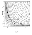
- FIG. 7 is a graph of the thermodynamic cycle of C.A.E.S. energy storage and recovery with a 6-stage CAT-G;
- FIG. 8 is a cross-section of CAT-G showing heat exchangers to warm each CAT-G section to T O ;
- FIG. 9 comprising FIGS. 9A and 9B , provides in 9 A a graph of temperature profile along the axis of a CAT-G and in 9 B a graph of pressure profile along the CAT-G of 9 A.
- the conventional turbine-engine is typically designed to draw in low pressure air which when used to burn hydrocarbon fuel (the source of input energy) generates a jet of high pressure output gas.
- This high pressure output can be used to produce either thrust, when it is ejected at high velocity (as in a turbojet aircraft engine), or mechanical power when it is used to spin a conventional jet turbine generator. In either case, the high pressure output produces enormous power.
- the CAT-G is clearly not a conventional turbine. However similar it is in design, there are some significant differences:
- the CAT-G must be designed for a rate of exhaust flow that is as slow as practical. (energy exhausted in the form of a high velocity output air flow is wasted. In a conventional turbine engine exhaust flow is as fast as practical. Furthermore, high air flow speed through the CAT-G would also exacerbate the difficulty of effective heat exchange within the compression sections.
- the representative pressure-volume expansion profile along the axis of the CAT-G is actually described by a 6-step piecewise approximation to the smooth P-V curve that is the T O Isotherm corresponding to an expansion/compression ratio of 8:1.
- the actual per-stage volume increases are not uniform (as they would be for true isothermal expansion), and the actual trans-rotor pressure drops (calculated for the 8:1 pressure differential) are substantially less than 40%.
- Compressed air is an attractive medium for energy storage because of its simplicity; and, through the use of the CAT-G, it is also attractive for the direct generation of electricity.
- the principal benefits of C.A.E.S. technology as described herein are that it:
- CAT-G electrical power generation requires that compressed air energy is supplied from the site of the storage location to the site of the CAT-G.
- Compressed air technology can be used to both transport the stored energy and to convert it into electrical power, but it is important to note when designing the system, that the required pressures and flow rates are different for each case.
- the CAT-G requires comparatively lower pressures and higher volumes of air flow (but not necessarily higher flow speed).
- the CAT-G is configured for a range of pressure head of only 8 to 22.4 atmospheres. Therefore, with pressure at 22.4 Atm and cross-sectional area about 1.0 m 2 flow speed of 1.75 m/s yields a power of about 20 MW.
- the wind or solar energy collection sites are far from the energy storage sites, it may be advantageous to move the energy directly through high pressure pipelines with moderate flow rates, and thereby avoid the use of electrical transmission lines and electric-powered air compressors located at the C.A.E.S. reservoir.
- compressed air energy should be supplied at comparatively low pressure and high mass flow rate. It follows that the CAT-G units should be placed relatively close to the energy reservoirs that support them.
- power generating capability is determined by the overall pressure drop across the CAT-G, the rate of airflow and the length of the turbine blade (i.e., the cross-sectional area of airflow). Power capacity increases with flow rate because of the increased input rate of compressed air energy. However, there is a point of diminishing returns where efficiency begins to drop off with incremental increases of flow speed. This is because the amount of kinetic energy lost to the output air stream becomes significant at higher flow rates (it is also likely that high flow rates will interfere with heat exchanger effectiveness). This behavior is demonstrated by the calculated results in FIG. 6 (for the 6-stage CAT-G configuration that is depicted in FIG. 2 ) operating with an input pressure range of 8 to 22.4 atmospheres.
- FIGS. 4A and 4B show that output power increases with flow rate. It shows, further, that output power in the multiple megawatt range is achievable with a realistic scale of design.
- FIG. 5 shows that power increases with input pressure; and that substantial power is produced even with relatively small cross-section and low flow speed.
- FIG. 6 shows that CAT-G efficiency drops slightly and output pressure increases with P S .
- Outlet flow speed increases with outlet pressure, and therefore the amount of initially stored energy that is expended as kinetic energy also increases.
- the velocity of expended air v is controlled by the aerodynamic design of the CAT-G and is, therefore, and important design variable for determining power. Power and efficiency calculations are based on treating the air flow speed v 0 into the CAT-G as an independent variable.
- the aerodynamics of flow through the CAT-G determines the actual value of v 0 that will result from the pressure drop applied across it.
- An extended model that includes blade design and other properties that control impedance to flow is thus needed to complete the design of a CAT-G device. Increasing this speed reduces efficiency.
- the isothermal compression of air is a familiar, simple and, in principle, a reversible process.
- the challenge here is to have the air expand and deliver work to a rotor system, and also approximate an isothermal process.
- This requires the effective injection of heat between the turbine stages. That is, aerodynamic flow must progress from the relatively cold outlet of a turbine rotor, through a region where heat is added, progressively raising air temperature and pressure, until ambient temperature is attained at the point of entrance to the successive rotor.
- aerodynamic flow must progress from the relatively cold outlet of a turbine rotor, through a region where heat is added, progressively raising air temperature and pressure, until ambient temperature is attained at the point of entrance to the successive rotor.
- C.A.E.S. including the pressure, volume, temperature and energy relationships.
- a specific example is considered where the energy is stored at a pressure of 8 Atm, in correspondence to the input pressure for the 6-stage CAT-G (discussed above).
- the analysis includes the relationship between the volume of the reservoir, the pressure and the total energy stored.
- W A ⁇ U A ; the change in internal energy.
- thermodynamic cycle for the isothermal compression of air from (P O ,V O ) to (P S ,V STORE ) begins with compression along the dashed-line T O Isotherm in FIG. 7 .
- This step provides the energy that is stored in the reservoirs, and which is issued to ‘fuel’ the energy recovery stage of the cycle.
- V S and V O as incremental volumes of air passing through the CAT-G that can be summed to equal the entire volume of stored air.
- the CAT-G expansion (or energy-recovery) process of FIG. 7 is shown by the heavy black line that zigzags downward from the point (P S ,V S ) in the upper left corner, to the point (P O ,V O ) in the lower right.
- the adiabatic segments of the path illustrate the sharp drop in pressure associated with adiabatic work. A significant drop in temperature is also associated with each of these pressure drops.
- the pressure levels for each stage diminish, stage by stage, in 6 steps.
- the vertical segments in this path correspond to pressure increases caused by the addition of heat by the heat exchangers that follow each rotor.
- the heat exchangers are in thermal contact with the heat reservoir.
- the energy-recovery path in FIG. 7 indicates that the sector volume increases very gradually in the first few stages.
- the increase in volume is more gradual than stated earlier (when describing isothermal air expansion) because adiabatic expansion follows a relationship whereby PV ⁇ is a constant ( ⁇ 26 1.39, for air), while for isothermal expansion, the exponent of V is 1! (Stage volume drops more slowly in the adiabatic process because of the higher exponent).
- FIG. 2 a phantom-view of the CAT-G.
- FIG. 8 shows the cross-section of two representative rotor stages, including heat exchangers (also used as stators to promote axial air flow).
- the cylindrical sections following each rotor contain a set of heat-exchange vanes that are aligned with the CAT-G axis. They are held at ambient temperature T O by means of circulation of fluid from the Heat Reservoir (See FIG. 1 ). Heating of the air stream corresponds to the vertical segments of the expansion path in the thermodynamic cycle of FIG. 7 . As shown there, and in FIG. 9A and FIG. 9B (below), the addition of heat raises both the temperature and pressure along the axis of the compression section. Raising air temperature back to T O is required in order to bring the CAT-G expansion path back to the Compression Isotherm after the adiabatic expansion at each rotor.
- FIG. 9 a shows the temperature dropping within the rotor and then increasing along the length of this cylinder as heat is absorbed.
- the length of the compression section, the rate of heat addition and the flow velocity must be determined so that the temperature reaches T O at the end of each compression section.
- FIG. 9 b shows pressure dropping within the rotor and then increasing as heat is absorbed in the compression section.
- FIG. 9 b An important concern is depicted in FIG. 9 b ; namely, whether it is possible for the air stream to flow from the relatively cool, low pressure at a rotor outlet, to the relatively warm and higher pressure at the adjacent rotor input.
- thermodynamic variables do support such a flow. This is demonstrated by an energy analysis of a typical CAT-G section.
- Q heat added to the system
- U is internal energy
- v flow velocity
- g is the acceleration of gravity
- y is altitude
- P pressure
- V Volume
- W is (shaft) work performed.
- v in 1 2 2 g( P S V S ⁇ P A1 V 1 )+ v 0 2 .
- the second part deals with flow through the compression tube.
- Efficiency is the ratio of energy produced to energy input per cycle.
- the CAT-G delivers electrical energy, but, for present purposes, the efficiency of mechanical to electrical conversion (i.e. the generators and combiners) are not included as part of the efficiency calculation. Instead we will calculate the (shaft) work (i.e., mechanical energy) delivered by the CAT-G cycle relative to the input energy which compressed the air.
- the thermodynamic efficiency equations are valid in general, ⁇ , as calculated here corresponds to the one particular CAT-G configuration, having 6 stages, which is used as our example and is both realistic and easy to analyze. No attempt has yet been made to optimize a detailed design for highest efficiency.
- ⁇ is given in general by:
- pressure is related to temperature by:
- Eq. (1), Eq. (2) and Eq. (3) can be iterated to calculate the intermediate pressures, volumes and temperatures through all the stages of a CAT-G.
- the thermodynamic parameters for all stages can be determined starting with a stated (chosen) pressure profile P i for the outlets of each rotor. For example, the input pressure at the 1 st rotor is P S , the volume is V s and the temperature is T O .
- Eq. (1) gives the temperature T A1 after adiabatic expansion to specified pressure P 1 .
- Eq. (2) gives the volume at the rotor outlet (i.e., the inlet to the 1 st compression section).
- Eq. (3) gives the (elevated) pressure at the outlet end of the compression section (i.e., the inlet to Rotor 2 ).
- Eq. (1) gives T A(i+1) ;
- Eq. (2) gives V i+1 , and
- Eq. (3) gives P ISO(i+1) .
- thermodynamic properties of a 6-stage CAT-G were simulated in this manner using an Excel spreadsheet, The resulting parameters were used to calculate the (shaft) work W Ai ; and the heat input Q INi for each stage and also to calculate the sums of these quantities.
- the overall efficiency of the CAT-G can readily be calculated from the sums of the per stage (shaft) work W A and the sums of the per stage work of isothermal compression W ISO using the familiar expression:
- Table 1 shows a representative thermodynamic calculation for a modified pressure profile that gives an overall efficiency of over 90%. This pressure profile is particularly attractive because it results in an equal percentage trans-rotor pressure drop across each rotor, and thereby allows every rotor to be set to operate at the peak c p coupling point (that is shown in FIG. 3 ).
- the table also shows that the optimal trans-rotor pressure drop for a 6-stage configuration is achieved with input pressure set at about 22.4 Atm. The conditions in Table 1, therefore, roughly correspond to the highest practical P S /P O ratio for a 6-stage CAT-G.
- the ‘Isotherm Pressure’ is the pressure (in Atm) at the end of each compression section (i.e., when the temperature returns to 300K).
- W Ai is the adiabatic (shaft) work for each rotor;
- W ISOi is the work supplied to (isothermally) compress the air from P ISO(i+l) , back to P ISOi , and
- Q INi is the heat added in each compression section. All tabulated energies are in units of joules/mole. Efficiencies are presented for each CAT-G stage, and for the overall CAT-G (which is the ratio of W A to the sum of W ISO and Q IN ).
- the number of ‘moles’ of air in volume V s is calculated from: n ⁇ P S ⁇ 10 3 /22.4 ‘moles’/m 3 at T ⁇ 300K.
- the present invention is a method and apparatus for storing and generating electrical power from compressed air. It will also be understood that the invention herein provides a way for turning renewable energy sources such as wind mills and solar receivers into an electricity source when needed and where needed using a relatively high efficiency system of generating electric energy from compressed air.
Abstract
Description
-
- High-pressure air from an external compressed air storage system is input to the first turbine stage at a controlled pressure and flow speed, and at ambient temperature.
- This air expands adiabatically against the resistance of the blades of the first rotor stage. This rotor is loaded by an electrical generator to extract energy. The first stage rotor and related generator are designed to extract a specific quantity of energy.
- The presence of a TO heat exchanger behind the first rotor is necessary to warm the air back to TO, and raise the air pressure in the larger volume compression section that precedes the second stage rotor.
- Because of the extraction of energy by the first rotor (which is accompanied by a drop in pressure) mechanical energy is imparted to the blades and to the rotating shaft to which they and the generator are physically attached. It is important to constrain the electrical generator power output in order to control the rotor speed (with each stage rotating independently of the others) so that each rotor functions at its peak efficiency.
- The design of the second turbine stage is similar to the first except it must have a somewhat larger diameter to accommodate the volume expansion of the air exiting the first rotor.
- Air flow speed must adjust with pressure and temperature throughout the CAT-G, to maintain constant mass-flow for the airstream.
- Stationary deflector blades (stators, not shown in
FIG. 2 ) are placed behind each rotor to keep the flow optimally aligned with respect to the CAT-G axis (i.e. the blades of the downstream rotating stage). It is likely that the mechanisms for heat-exchange will be integrated with these stators. - Systematically, stages with increasing diameter are cascaded so as to:
- extract electrical power as the air pressure is reduced by the adiabatic work delivered to the upstream turbine blades;
- maintain designated profiles along the turbine axis for air pressure, temperature and flow rate;
- inject heat and extract energy, stage by stage, until atmospheric pressure and ambient temperature are reached at the system outlet; and,
- generate electrical energy at every turbine stage that is combined to form the total turbine-generator energy output.
-
- utilizes durable and inexpensive equipment, such as storage tanks and pipelines, which can be made from composite materials;
- is environmentally friendly in that “spills” do not produce any environmental hazards (as escaping material would merely be air or warm water);
- is relatively safe in that an accidental release of compressed air energy primarily emits a low mass material (air) which even at a high velocity does not have the potential to do serious damage or injury as a result of the transfer of a great deal of momentum; and,
- can effectively use concrete and steel shell enclosures to contain any fragments originating from the rupture of high pressure tanks or pipelines in a manner that seems straight-forward and inexpensive; the main requirement being adequacy to prevent high strength, low density materials, such as plastic composites or fiber glass, from escaping containment.
-
- −WA+Q=(CP−CV)TO[(PS/PO)α−1]=nRTO[(PS/PO)α−1]=PSVSTORE[(PS/PO)α−1] with (PS/PO)=8 the excess work is about 0.79 PSVSTORE. Hence, for an 8:1 compression, the excess is about 38% of the total isothermal work required to compress the air from (PO,VO).
Q=U f −U i+(v f 2 −v i 2)/2 g+y f −y i +P f V f −P i V i +W;
(Outlet velocity)2=−2 g(P f V f −P i V i)+(Inlet velocity)2
And noting that this outlet velocity equals vini in
vin1 2=2 g(P S V S −P A1 V 1)+v 0 2.
vf 1 2/2 g=vin1 2/2 g−V 1(P ISO1 −P A1);
vf 1 2/2 g=(P S V S −P A1 V 1)−V 1(P ISO1 −P A1)+v o 2/2 g
or,
vf 1 2/2 g=P S V S −P ISO1 V 1 +v o 2/2 g.
vf1=vo.
Where the total input energy is WISO, which includes the energy that produced the added heat QIN that is drawn from the heat reservoir.
W A =C V(T i −T f)
W A =C V[(T O −T A1)+(T O −T A2)+(T O −T A3)+ . . . +(T O −T A6)]
where the right-hand side corresponds to the temperature and pressure before the adiabatic expansion, and the left, after the adiabatic expansion. Similarly, volume before and after (with the same convention) is related to temperature by:
V i ·T Ai 1/(γ−1) =V S ·T 0 1/(γ−1), Eq. (2)
Q INi =C V(T O −T Ai).
where PISOi and the other three parameters in Eq. (3) all sit on the TO isotherm. Eq. (1), Eq. (2) and Eq. (3) can be iterated to calculate the intermediate pressures, volumes and temperatures through all the stages of a CAT-G. The thermodynamic parameters for all stages can be determined starting with a stated (chosen) pressure profile Pi for the outlets of each rotor. For example, the input pressure at the 1st rotor is PS, the volume is Vs and the temperature is TO. Eq. (1) gives the temperature TA1 after adiabatic expansion to specified pressure P1. Eq. (2) gives the volume at the rotor outlet (i.e., the inlet to the 1st compression section). Eq. (3) gives the (elevated) pressure at the outlet end of the compression section (i.e., the inlet to Rotor 2). In general, starting with rotor inlet pressure PISOi, and next stage (specified) rotor outlet pressure (from the design profile) P(i+1), Eq. (1) gives TA(i+1); Eq. (2) gives Vi+1, and Eq. (3) gives PISO(i+1).
W ISO =RT O ln(P S P O), per mole.
W ISOi =RT O ln(P i /P (i+l)), per mole.
V S =Ac·v·δt;
with output (shaft) power given by WA/δt.
n≈PS·103/22.4 ‘moles’/m3 at T≈300K.
| TABLE 1 |
| Calculated Results for 6-Stage CAT-G with Ps = 22.4 Atm |
| [Energies are in joules/mole, with values tabulated for Vs = 1 m3]* |
| Rotor | ||||||||||
| Output | ||||||||||
| Pressure | Rotor Output | Output | Pressure | Isotherm | ||||||
| Stage | Atm | Temperature K | Volume * Vs | Drop | Pressure | WA | WISO | Qin | ||
| Efficiency | ||||||||||
| 0 | 22.40 | 300.00 | 1.00 | 22.40 | ||||||
| 1 | 13.34 | 259.41 | 1.45 | 40.4% | 15.43 | 865 | 930 | 865 | 93.1% | |
| 2 | 7.95 | 249.04 | 2.34 | 40.4% | 9.57 | 1086 | 1191 | 1086 | 91.2% | |
| 3 | 4.73 | 246.20 | 3.88 | 40.4% | 5.77 | 1147 | 1264 | 1147 | 90.7% | |
| 4 | 2.82 | 245.41 | 6.50 | 40.4% | 3.45 | 1164 | 1284 | 1164 | 90.6% | |
| 5 | 1.68 | 245.19 | 10.90 | 40.4% | 2.05 | 1168 | 1290 | 1168 | 90.6% | |
| 6 | 1.00 | 245.13 | 18.30 | 40.4% | 1.22 | 1170 | 1292 | 1170 | 90.5% | |
| Overall | ||||||||||
| Efficiency | ||||||||||
| Total | 6600 | 7251 | 6600 | 91.0% | ||||||
| *Energy scales as Vs, which equals cross-sectional flow area of 1st rotor, Ac, multiplied by 1 meter of flow distance. | ||||||||||
Claims (16)
Priority Applications (6)
| Application Number | Priority Date | Filing Date | Title |
|---|---|---|---|
| US12/800,671 US8347628B2 (en) | 2009-08-18 | 2010-05-19 | Power generation directly from compressed air for exploiting wind and solar power |
| ES10810274.0T ES2662776T3 (en) | 2009-08-18 | 2010-08-17 | System and method of power generation |
| PT108102740T PT2483543T (en) | 2009-08-18 | 2010-08-17 | Power generation system and method |
| PCT/US2010/002263 WO2011022052A2 (en) | 2009-08-18 | 2010-08-17 | Power generation directly from compressed air for exploiting wind and solar power |
| EP10810274.0A EP2483543B1 (en) | 2009-08-18 | 2010-08-17 | Power generation system and method |
| DK10810274.0T DK2483543T3 (en) | 2009-08-18 | 2010-08-17 | Energy generation system and method |
Applications Claiming Priority (2)
| Application Number | Priority Date | Filing Date | Title |
|---|---|---|---|
| US27461409P | 2009-08-18 | 2009-08-18 | |
| US12/800,671 US8347628B2 (en) | 2009-08-18 | 2010-05-19 | Power generation directly from compressed air for exploiting wind and solar power |
Publications (2)
| Publication Number | Publication Date |
|---|---|
| US20110041501A1 US20110041501A1 (en) | 2011-02-24 |
| US8347628B2 true US8347628B2 (en) | 2013-01-08 |
Family
ID=43604182
Family Applications (1)
| Application Number | Title | Priority Date | Filing Date |
|---|---|---|---|
| US12/800,671 Active 2031-05-31 US8347628B2 (en) | 2009-08-18 | 2010-05-19 | Power generation directly from compressed air for exploiting wind and solar power |
Country Status (6)
| Country | Link |
|---|---|
| US (1) | US8347628B2 (en) |
| EP (1) | EP2483543B1 (en) |
| DK (1) | DK2483543T3 (en) |
| ES (1) | ES2662776T3 (en) |
| PT (1) | PT2483543T (en) |
| WO (1) | WO2011022052A2 (en) |
Cited By (10)
| Publication number | Priority date | Publication date | Assignee | Title |
|---|---|---|---|---|
| US20110148196A1 (en) * | 2009-12-22 | 2011-06-23 | Williams Kevin James | Distributed energy source system |
| US20130008887A1 (en) * | 2011-07-07 | 2013-01-10 | Wan Chun Hsu | Water Heating System |
| US20140199160A1 (en) * | 2011-08-09 | 2014-07-17 | Paul Merswolke | Wind turbine with two sets of blades and method of operation thereof |
| US8978380B2 (en) | 2010-08-10 | 2015-03-17 | Dresser-Rand Company | Adiabatic compressed air energy storage process |
| US20170159649A1 (en) * | 2014-07-31 | 2017-06-08 | Kabushiki Kaisha Kobe Seiko Sho (Kobe Steel, Ltd.) | Compressed air storage and power generation device and compressed air storage and power generation method |
| US9852819B2 (en) | 2014-01-22 | 2017-12-26 | Willard Harvey Wattenburg | Passive nuclear reactor cooling system using compressed gas energy and coolant storage outside nuclear plant |
| US9938896B2 (en) | 2013-04-03 | 2018-04-10 | Sigma Energy Storage Inc. | Compressed air energy storage and recovery |
| US10049776B2 (en) | 2014-01-22 | 2018-08-14 | Willard Harvey Wattenburg | Compressed air, utility-scale, non-polluting energy storage and nuclear reactor emergency cooling system using thermal power plant waste heat |
| US11300103B2 (en) | 2019-01-25 | 2022-04-12 | Haralambos Theodoros Dragonas | Wind-powered energy generator system |
| WO2023102250A1 (en) * | 2021-12-04 | 2023-06-08 | Connors Christopher Edward | Compressed air energy storage and distribution pipeline system and method |
Families Citing this family (23)
| Publication number | Priority date | Publication date | Assignee | Title |
|---|---|---|---|---|
| WO2010070539A1 (en) * | 2008-12-19 | 2010-06-24 | Nxp B.V. | Enhanced smart card usage |
| CN201705575U (en) * | 2010-06-17 | 2011-01-12 | 王正德 | Energy-storage type wind power generating system |
| US8739533B2 (en) | 2010-12-02 | 2014-06-03 | Or Yogev | Solar augmented wind turbine for stable and dispatchable utility scale power generation |
| WO2012122004A2 (en) * | 2011-03-04 | 2012-09-13 | Hugo Ronald J | Distributed compressed air energy storage system and method |
| US20120310855A1 (en) * | 2011-06-06 | 2012-12-06 | International Business Machines Corporation | Systems and methods for determining a site for an energy conversion device |
| WO2013043754A1 (en) | 2011-09-20 | 2013-03-28 | Lightsail Energy, Inc. | Compressed gas energy storage system using turbine |
| EP2574865A1 (en) * | 2011-09-29 | 2013-04-03 | Siemens Aktiengesellschaft | Energy storage device and energy storage method |
| DE102012102897A1 (en) * | 2011-12-04 | 2013-06-06 | Ed. Züblin Ag | Compressed gas storage plant |
| US8457800B2 (en) | 2012-01-19 | 2013-06-04 | General Compression, Inc. | System and method for conserving energy resources through storage and delivery of renewable energy |
| US9275767B2 (en) * | 2013-02-06 | 2016-03-01 | Westinghouse Electric Company Llc | Systems and methods for generating power employing VES air supply stored energy |
| CN104153946B (en) * | 2013-05-14 | 2017-07-14 | 国家电网公司 | A kind of cool and thermal power water polygenerations systeme for comprehensively utilizing wind energy and sea water heat energy |
| CH708072A1 (en) * | 2013-05-17 | 2014-11-28 | Swiss Green Systems Sagl | Device for the production of electrical energy. |
| GB201310717D0 (en) * | 2013-06-16 | 2013-07-31 | Garvey Seamus D | Direct-drive power conversion system for wind turbines compatible with energy storage |
| CN104963815B (en) * | 2015-07-22 | 2018-04-06 | 刘金怀 | A kind of high power wind power generation device |
| CN105545601A (en) * | 2016-01-05 | 2016-05-04 | 王振铎 | Wind energy conversion and large-scale physical energy storage structure device |
| CN205559070U (en) | 2016-03-04 | 2016-09-07 | 王力丰 | Use system and aircraft of compressed air as application of force source |
| CN105649775B (en) * | 2016-03-04 | 2017-06-23 | 王力丰 | With system and method, aircraft that compressed air is force source |
| CN106288510B (en) * | 2016-07-27 | 2019-03-08 | 重庆京天能源投资(集团)股份有限公司 | It provides multiple forms of energy to complement each other energy integration supply system |
| CN110145438A (en) * | 2019-06-18 | 2019-08-20 | 王振铎 | Wind energy, solar energy and the energy-storage system applied in modern ecological pesticide herd forestry |
| US20210388757A1 (en) * | 2020-06-15 | 2021-12-16 | Bechtel Infrastructure and Power Corporation | Air energy storage with internal combustion engines |
| CN111734501A (en) * | 2020-06-19 | 2020-10-02 | 吴勉之 | Airflow power generation system |
| US20220235661A1 (en) * | 2021-01-25 | 2022-07-28 | Air Liquide Large Industries U.S. Lp | Nitrogen driven dc generator |
| WO2023130048A1 (en) * | 2021-12-29 | 2023-07-06 | Mark Patton | Electrical power generating system |
Citations (16)
| Publication number | Priority date | Publication date | Assignee | Title |
|---|---|---|---|---|
| US2638741A (en) * | 1948-08-11 | 1953-05-19 | Jr Henry M Putman | Axial flow gas turbine having reheating means and specially shaped rotor and stator blades to provide isothermal expansion |
| US3786631A (en) * | 1971-09-23 | 1974-01-22 | L Manning | Nitrogen vapor engine |
| US3797247A (en) * | 1972-08-10 | 1974-03-19 | E Schwartzman | Compound brayton-cycle engine |
| US3996741A (en) * | 1975-06-05 | 1976-12-14 | Herberg George M | Energy storage system |
| US4003786A (en) * | 1975-09-16 | 1977-01-18 | Exxon Research And Engineering Company | Thermal energy storage and utilization system |
| US4100745A (en) * | 1976-03-15 | 1978-07-18 | Bbc Brown Boveri & Company Limited | Thermal power plant with compressed air storage |
| US4751814A (en) * | 1985-06-21 | 1988-06-21 | General Electric Company | Air cycle thermodynamic conversion system |
| US4885912A (en) * | 1987-05-13 | 1989-12-12 | Gibbs & Hill, Inc. | Compressed air turbomachinery cycle with reheat and high pressure air preheating in recuperator |
| US5473899A (en) * | 1993-06-10 | 1995-12-12 | Viteri; Fermin | Turbomachinery for Modified Ericsson engines and other power/refrigeration applications |
| US5685155A (en) * | 1993-12-09 | 1997-11-11 | Brown; Charles V. | Method for energy conversion |
| US6378287B2 (en) * | 2000-03-17 | 2002-04-30 | Kenneth F. Griffiths | Multi-stage turbomachine and design method |
| US20050210878A1 (en) * | 2001-05-15 | 2005-09-29 | Daniel Ashikian | System and method for storing, disseminating, and utilizing energy in the form of gas compression and expansion including a thermo-dynamic battery |
| US7086231B2 (en) * | 2003-02-05 | 2006-08-08 | Active Power, Inc. | Thermal and compressed air storage system |
| US20070095069A1 (en) * | 2005-11-03 | 2007-05-03 | General Electric Company | Power generation systems and method of operating same |
| US20090016876A1 (en) * | 2004-06-03 | 2009-01-15 | Hitachi, Ltd. | Axial turbine |
| US20090145103A1 (en) * | 2007-01-25 | 2009-06-11 | Michael Nakhamkin | Conversion of combined cycle power plant to compressed air energy storage power plant |
Family Cites Families (9)
| Publication number | Priority date | Publication date | Assignee | Title |
|---|---|---|---|---|
| US2407166A (en) * | 1941-11-08 | 1946-09-03 | Kreitner Johann | Heat cycle |
| CA2061962C (en) * | 1992-02-27 | 2000-08-22 | Thomas L. Cosby | Maximum ambient cycle |
| IL108546A (en) * | 1994-02-03 | 1997-01-10 | Israel Electric Corp Ltd | Compressed air energy storage method and system |
| US7784261B2 (en) * | 2006-05-25 | 2010-08-31 | Siemens Energy, Inc. | Combined cycle power plant |
| US7669423B2 (en) * | 2007-01-25 | 2010-03-02 | Michael Nakhamkin | Operating method for CAES plant using humidified air in a bottoming cycle expander |
| US20080178601A1 (en) * | 2007-01-25 | 2008-07-31 | Michael Nakhamkin | Power augmentation of combustion turbines with compressed air energy storage and additional expander with airflow extraction and injection thereof upstream of combustors |
| US20090021012A1 (en) * | 2007-07-20 | 2009-01-22 | Stull Mark A | Integrated wind-power electrical generation and compressed air energy storage system |
| US20090033102A1 (en) * | 2007-07-30 | 2009-02-05 | Enis Ben M | Method and apparatus for using wind turbines to generate and supply uninterrupted power to locations remote from the power grid |
| WO2009094226A1 (en) * | 2008-01-24 | 2009-07-30 | Enis Ben M | Method and apparatus for using solar energy to enhance the operation of a compressed air energy storage system |
-
2010
- 2010-05-19 US US12/800,671 patent/US8347628B2/en active Active
- 2010-08-17 DK DK10810274.0T patent/DK2483543T3/en active
- 2010-08-17 ES ES10810274.0T patent/ES2662776T3/en active Active
- 2010-08-17 PT PT108102740T patent/PT2483543T/en unknown
- 2010-08-17 EP EP10810274.0A patent/EP2483543B1/en active Active
- 2010-08-17 WO PCT/US2010/002263 patent/WO2011022052A2/en active Application Filing
Patent Citations (16)
| Publication number | Priority date | Publication date | Assignee | Title |
|---|---|---|---|---|
| US2638741A (en) * | 1948-08-11 | 1953-05-19 | Jr Henry M Putman | Axial flow gas turbine having reheating means and specially shaped rotor and stator blades to provide isothermal expansion |
| US3786631A (en) * | 1971-09-23 | 1974-01-22 | L Manning | Nitrogen vapor engine |
| US3797247A (en) * | 1972-08-10 | 1974-03-19 | E Schwartzman | Compound brayton-cycle engine |
| US3996741A (en) * | 1975-06-05 | 1976-12-14 | Herberg George M | Energy storage system |
| US4003786A (en) * | 1975-09-16 | 1977-01-18 | Exxon Research And Engineering Company | Thermal energy storage and utilization system |
| US4100745A (en) * | 1976-03-15 | 1978-07-18 | Bbc Brown Boveri & Company Limited | Thermal power plant with compressed air storage |
| US4751814A (en) * | 1985-06-21 | 1988-06-21 | General Electric Company | Air cycle thermodynamic conversion system |
| US4885912A (en) * | 1987-05-13 | 1989-12-12 | Gibbs & Hill, Inc. | Compressed air turbomachinery cycle with reheat and high pressure air preheating in recuperator |
| US5473899A (en) * | 1993-06-10 | 1995-12-12 | Viteri; Fermin | Turbomachinery for Modified Ericsson engines and other power/refrigeration applications |
| US5685155A (en) * | 1993-12-09 | 1997-11-11 | Brown; Charles V. | Method for energy conversion |
| US6378287B2 (en) * | 2000-03-17 | 2002-04-30 | Kenneth F. Griffiths | Multi-stage turbomachine and design method |
| US20050210878A1 (en) * | 2001-05-15 | 2005-09-29 | Daniel Ashikian | System and method for storing, disseminating, and utilizing energy in the form of gas compression and expansion including a thermo-dynamic battery |
| US7086231B2 (en) * | 2003-02-05 | 2006-08-08 | Active Power, Inc. | Thermal and compressed air storage system |
| US20090016876A1 (en) * | 2004-06-03 | 2009-01-15 | Hitachi, Ltd. | Axial turbine |
| US20070095069A1 (en) * | 2005-11-03 | 2007-05-03 | General Electric Company | Power generation systems and method of operating same |
| US20090145103A1 (en) * | 2007-01-25 | 2009-06-11 | Michael Nakhamkin | Conversion of combined cycle power plant to compressed air energy storage power plant |
Cited By (12)
| Publication number | Priority date | Publication date | Assignee | Title |
|---|---|---|---|---|
| US20110148196A1 (en) * | 2009-12-22 | 2011-06-23 | Williams Kevin James | Distributed energy source system |
| US9559522B2 (en) * | 2009-12-22 | 2017-01-31 | Kevin James WILLIAMS | Distributed energy source system |
| US8978380B2 (en) | 2010-08-10 | 2015-03-17 | Dresser-Rand Company | Adiabatic compressed air energy storage process |
| US20130008887A1 (en) * | 2011-07-07 | 2013-01-10 | Wan Chun Hsu | Water Heating System |
| US20140199160A1 (en) * | 2011-08-09 | 2014-07-17 | Paul Merswolke | Wind turbine with two sets of blades and method of operation thereof |
| US9938896B2 (en) | 2013-04-03 | 2018-04-10 | Sigma Energy Storage Inc. | Compressed air energy storage and recovery |
| US9852819B2 (en) | 2014-01-22 | 2017-12-26 | Willard Harvey Wattenburg | Passive nuclear reactor cooling system using compressed gas energy and coolant storage outside nuclear plant |
| US9966154B1 (en) | 2014-01-22 | 2018-05-08 | Willard Harvey Wattenburg | Cooling overheating reactor using compressed gas to propel liquid to reactor |
| US10049776B2 (en) | 2014-01-22 | 2018-08-14 | Willard Harvey Wattenburg | Compressed air, utility-scale, non-polluting energy storage and nuclear reactor emergency cooling system using thermal power plant waste heat |
| US20170159649A1 (en) * | 2014-07-31 | 2017-06-08 | Kabushiki Kaisha Kobe Seiko Sho (Kobe Steel, Ltd.) | Compressed air storage and power generation device and compressed air storage and power generation method |
| US11300103B2 (en) | 2019-01-25 | 2022-04-12 | Haralambos Theodoros Dragonas | Wind-powered energy generator system |
| WO2023102250A1 (en) * | 2021-12-04 | 2023-06-08 | Connors Christopher Edward | Compressed air energy storage and distribution pipeline system and method |
Also Published As
| Publication number | Publication date |
|---|---|
| WO2011022052A3 (en) | 2011-11-17 |
| EP2483543A4 (en) | 2014-10-01 |
| ES2662776T3 (en) | 2018-04-09 |
| EP2483543B1 (en) | 2017-12-13 |
| PT2483543T (en) | 2018-03-15 |
| DK2483543T3 (en) | 2018-03-19 |
| EP2483543A2 (en) | 2012-08-08 |
| US20110041501A1 (en) | 2011-02-24 |
| WO2011022052A2 (en) | 2011-02-24 |
Similar Documents
| Publication | Publication Date | Title |
|---|---|---|
| US8347628B2 (en) | Power generation directly from compressed air for exploiting wind and solar power | |
| US20190003384A1 (en) | Compressed air energy storage and recovery | |
| Wang et al. | Experimental study of compressed air energy storage system with thermal energy storage | |
| EP3384143B1 (en) | Energy storage system | |
| Grazzini et al. | A thermodynamic analysis of multistage adiabatic CAES | |
| CN100425925C (en) | Electricity generating, air conditioning and heating apparatus utilizing natural medium and solar energy or waste heat | |
| US10519923B2 (en) | Near isothermal combined compressed gas/pumped-hydro electricity storage with waste heat recovery capabilities | |
| Qin et al. | Spray-cooling concept for wind-based compressed air energy storage | |
| Zhang et al. | Combined cooling, heating, and power generation performance of pumped thermal electricity storage system based on Brayton cycle | |
| CN205779057U (en) | A kind of enclosed combined cooling and power energy-storage system | |
| Zhao et al. | Performance analysis of a self-condensation compressed carbon dioxide energy storage system with vortex tube | |
| CN105863753A (en) | Closed cooling and power combined energy storage system | |
| CN107299891A (en) | A kind of non-compensation combustion type compressed-air energy-storage system | |
| EP3011203B1 (en) | Direct-drive power conversion system for wind turbines compatible with energy storage | |
| Dib et al. | Thermodynamic investigation of quasi-isothermal air compression/expansion for energy storage | |
| Song et al. | Thermodynamic analysis and algorithm optimisation of a multi-stage compression adiabatic compressed air energy storage system | |
| US20190120213A1 (en) | Amalthea venturi thermal cycle | |
| Akbarzadeh et al. | Formulation and analysis of the heat pipe turbine for production of power from renewable sources | |
| Rabbani et al. | Thermodynamic assessment of a wind turbine based combined cycle | |
| Sathish et al. | Analysis of a 10 MW recompression supercritical carbon dioxide cycle for tropical climatic conditions | |
| Alami et al. | Compressed-air energy storage Systems | |
| Li et al. | Comprehensive thermo-exploration of a near-isothermal compressed air energy storage system with a pre-compressing process and heat pump discharging | |
| Patil et al. | Comparative assessment of different types of ocean compressed air energy storage systems based on exergy analysis | |
| CN209925091U (en) | Hot-flow type power generation device | |
| US20220316483A1 (en) | Systems and methods for improving the performance of air-driven generators using solar thermal heating |
Legal Events
| Date | Code | Title | Description |
|---|---|---|---|
| STCF | Information on status: patent grant |
Free format text: PATENTED CASE |
|
| AS | Assignment |
Owner name: CAESAR EXPERIMENTAL, LLC, NEW YORK Free format text: ASSIGNMENT OF ASSIGNORS INTEREST;ASSIGNOR:GERARD, HENRY MICHAEL;REEL/FRAME:032310/0553 Effective date: 20130118 |
|
| FPAY | Fee payment |
Year of fee payment: 4 |
|
| SULP | Surcharge for late payment | ||
| FEPP | Fee payment procedure |
Free format text: MAINTENANCE FEE REMINDER MAILED (ORIGINAL EVENT CODE: REM.); ENTITY STATUS OF PATENT OWNER: SMALL ENTITY |
|
| FEPP | Fee payment procedure |
Free format text: 7.5 YR SURCHARGE - LATE PMT W/IN 6 MO, SMALL ENTITY (ORIGINAL EVENT CODE: M2555); ENTITY STATUS OF PATENT OWNER: SMALL ENTITY |
|
| MAFP | Maintenance fee payment |
Free format text: PAYMENT OF MAINTENANCE FEE, 8TH YR, SMALL ENTITY (ORIGINAL EVENT CODE: M2552); ENTITY STATUS OF PATENT OWNER: SMALL ENTITY Year of fee payment: 8 |