US8340358B2 - Visual camouflage with thermal and radar suppression and methods of making the same - Google Patents
Visual camouflage with thermal and radar suppression and methods of making the same Download PDFInfo
- Publication number
- US8340358B2 US8340358B2 US12/386,986 US38698609A US8340358B2 US 8340358 B2 US8340358 B2 US 8340358B2 US 38698609 A US38698609 A US 38698609A US 8340358 B2 US8340358 B2 US 8340358B2
- Authority
- US
- United States
- Prior art keywords
- layer
- camouflage
- nanomaterial
- camouflage pattern
- vinyl
- Prior art date
- Legal status (The legal status is an assumption and is not a legal conclusion. Google has not performed a legal analysis and makes no representation as to the accuracy of the status listed.)
- Active, expires
Links
Images


Classifications
-
- F—MECHANICAL ENGINEERING; LIGHTING; HEATING; WEAPONS; BLASTING
- F41—WEAPONS
- F41H—ARMOUR; ARMOURED TURRETS; ARMOURED OR ARMED VEHICLES; MEANS OF ATTACK OR DEFENCE, e.g. CAMOUFLAGE, IN GENERAL
- F41H3/00—Camouflage, i.e. means or methods for concealment or disguise
- F41H3/02—Flexible, e.g. fabric covers, e.g. screens, nets characterised by their material or structure
-
- Y—GENERAL TAGGING OF NEW TECHNOLOGICAL DEVELOPMENTS; GENERAL TAGGING OF CROSS-SECTIONAL TECHNOLOGIES SPANNING OVER SEVERAL SECTIONS OF THE IPC; TECHNICAL SUBJECTS COVERED BY FORMER USPC CROSS-REFERENCE ART COLLECTIONS [XRACs] AND DIGESTS
- Y10—TECHNICAL SUBJECTS COVERED BY FORMER USPC
- Y10T—TECHNICAL SUBJECTS COVERED BY FORMER US CLASSIFICATION
- Y10T428/00—Stock material or miscellaneous articles
- Y10T428/24—Structurally defined web or sheet [e.g., overall dimension, etc.]
- Y10T428/24802—Discontinuous or differential coating, impregnation or bond [e.g., artwork, printing, retouched photograph, etc.]
- Y10T428/24851—Intermediate layer is discontinuous or differential
Definitions
- Systems and methods for visual camouflage that provide thermal and radar suppression are provided.
- systems and methods for the creation of a tactical vinyl graphic film both adhesive and non-adhesive embodiments
- simultaneous visual camouflage, concealment and deception and suppression of the radar and thermal signatures are accomplished by the use of nanomaterials.
- Precision-guided munitions exist that can be delivered by artillery, missiles, and aircraft and that can operate in the IR region of the electromagnetic spectrum. These capabilities are available through internal manufacturing or purchase on the world market. These advanced imaging sights and sensors allow enemies to acquire and engage targets through visual smoke, at night, and under adverse weather conditions.
- camouflage paint, paint additives, tarps, nets and foams have been developed for visual camouflage and thermal and radar signature suppression.
- CARC paint is the ideal paint for camouflage and chemical protection, it is important to realize that it directly contributes to the problem.
- CARC paint is considered environmentally hazardous, and its application requires Environmental Protection Agency (“EPA”) approved safety equipment and facilities.
- Tarps and nets can provide separation between the vehicles being hidden and the point of observation of the detection systems used. Tarps and nets can suppress thermal signature as well as signals detected by radar. However, both tarps and nets can be heavy and cumbersome to use. They can thus interfere with mobility.
- foam appears to have promise regarding thermal and radar suppression.
- foam has been hard to effectively use in such camouflage, concealment or deception applications because the foam was not functional in terms of visual camouflage.
- camouflage systems and methods that use a vinyl layer with a camouflage pattern printed thereon to provide visual camouflage, concealment and deception and include nanomaterials to provide suppression of the radar and/or thermal signatures are provided.
- FIGS. 1A-1H illustrate schematic views of embodiments of a multi-layered visual camouflage system with thermal and radar suppression according to the present subject matter
- FIGS. 2A-2B illustrate schematic views of other embodiments of a multi-layered visual camouflage system with thermal and radar suppression according to the present subject matter
- FIGS. 3A-3E illustrate schematic views of further embodiments of a multi-layered visual camouflage system with thermal and radar suppression according to the present subject matter
- FIG. 4 illustrates an embodiment of a physical item having an embodiment of a camouflage pattern or arrangement attached thereto according to the present subject matter
- FIG. 5 illustrates an embodiment of panels having a camouflage pattern printed thereon that can be attached to a physical item according to the present subject matter
- FIGS. 6A and 6B illustrate embodiments of a camouflage pattern or arrangement according to the present subject matter
- FIGS. 7A and 7B illustrate other embodiments of a camouflage pattern or arrangement according to the present subject matter
- FIG. 8 illustrates a perspective view of a physical item having embodiments of a camouflage pattern or arrangement placed thereon according to the present subject matter
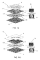
- FIGS. 9-15 illustrate steps for creating embodiments of a camouflage pattern or arrangement according to the present subject matter
- FIGS. 16-25 illustrate steps for creating other embodiments of a camouflage pattern or arrangement according to the present subject matter
- FIGS. 26-29 illustrate steps for an embodiment of a mock-up process for embodiments of a camouflage pattern or arrangement according to the present subject matter.
- FIG. 30 illustrates a further embodiment of a camouflage pattern or arrangement according to the present subject matter.
- Site-specific as used herein means a specific local terrain, nautical position, or airspace where a physical item will be located or operating, or the environmental characteristics which would be found in the intended operating environment of the physical item.
- Pattern as used herein means any color and/or imagery, including, but not limited to camouflage patterns, repeating and non-repeating designs, deceptive designs, such as imagery that give the perception that a vehicle is an ambulance, taxi, police vehicle, or the like, and outward physical characteristics of a physical item such as rust, dents scratches, or the like, printed to a vinyl adhesive layer.
- Disruptive pattern as used herein means a pattern of shapes that when configured on an image will cause visual confusion.
- “Distortions,” “distorting,” and variations thereof as used herein means the changing of at least a portion of an image by manipulating the focal lengths within those portions of the image, adding to a first image a portion of the image or a portion of different image that has a different focal length than the first image, or adding shapes of color that change the appearance of the image.
- Focal lengths can include improper focal lengths that cause at least a portion of the image to appear to be out of focus.
- Fluor lengths as used herein means the distance at which an image will come into visual focus either by a human observer or through electronic, electromechanical and/or optical methods and devices. Focal lengths can include improper focal lengths that cause at least a portion of the image to appear to be out of focus.
- Image-editing program as used herein means a computer program used to edit or change an image. Examples include Adobe PHOTOSHOP®, PAINT.NET® and PICASA®.
- Image as used herein means the optical counterpart of an object or environment produced by graphical drawing by a person, a device (such as a computer) or a combination thereof.
- the optical counterpart of the object can also be produced by an optical device electromechanical device or electronic device.
- image can be used to refer to a whole image, for example, a photographic image as taken by a photographic device, or a portion thereof.
- Physical item as used herein can include, but is not limited to any and all types of vehicles (land, air and sea, and rail/manned & unmanned), aircraft, watercraft, structures, buildings, pipes and piping, equipment, weapons, hardware, and other items used for military or other purposes where camouflage can enhance its effective use or where the need for camouflage concealment or deception exists.
- vehicles such as, but is not limited to any and all types of vehicles (land, air and sea, and rail/manned & unmanned), aircraft, watercraft, structures, buildings, pipes and piping, equipment, weapons, hardware, and other items used for military or other purposes where camouflage can enhance its effective use or where the need for camouflage concealment or deception exists.
- Nanomaterial as used herein means nano-scale technology, such as nanoparticles or clusters of nanoparticles. Nanoparticles behave as a whole unit in terms of its transport and properties. Nanomaterial can include but is not limited to aerogel in powder form, clusters of powdered aerogel, microspheres and clusters of microspheres.
- Camouflage systems and methods that use a vinyl layer with a camouflage pattern printed thereon to provide visual camouflage, concealment and deception and include nanomaterials to provide suppression of radar and/or thermal signatures are described herein. Simultaneous visual camouflage, concealment and deception and suppression of the radar and thermal signature are accomplished by imagery and the use of nanomaterials.
- Such visual camouflage and thermal and radar suppression systems that incorporate a vinyl layer and nanomaterial into a light-weight application for vehicles (manned and unmanned, land, sea, and air), hardware, equipment and engineered structures can fulfill advanced counter-measure needs in response to the developing sensor technologies.
- the visual camouflage system can provide at least one of thermal or radar suppression.
- the system can include a vinyl layer having a camouflage pattern on a front surface of the vinyl layer.
- the camouflage pattern can be a site-specific camouflage pattern.
- a laminate layer can be secured over the front surface of the vinyl layer with the laminate layer coating the camouflage pattern to provide protection to the camouflage pattern and strengthen the vinyl layer.
- One or more nanomaterials can be disposed on at least one of the vinyl layer, camouflage pattern, or the laminate to provide at least one of thermal or radar suppression.
- the system with its nano-scale technology, ultra-light weight, and unique thin film (adhesive or non-adhesive) graphic vinyl based structure with visual camouflage thereon operates inter-dependently to provide simultaneous concealment, deception and thermal and radar suppression.
- the advanced visual camouflage can be accomplished through the use of, for example, high megapixel digital photography that is specific to the intended site, mission environment, or area of operation. It is printed in high detail and at a high resolution by suitably large format printing means, such as inkjet technology onto a vinyl thin-film.
- This tactical vinyl graphic film can then have an over-laminate protective barrier with a low-gloss finish laminated thereto.
- Thermal and radar signature suppression counter-measures are embedded into or between layers of this ultra-thin, lightweight system in the form of nano-scale, air or gas-filled microspheres or micro-balloons that can also be metallic coated, such as cenospheres, and pulverized aerogels that consist of over 90% air in nano-scale pores that inhibit heat transfer with low density. These materials in combination with one another provide the mechanism for simultaneous visual camouflage and thermal and radar signature suppression.
- camouflage system Once the camouflage system is created, it can be applied to military and tactical vehicles (manned and unmanned land, sea or air), military hardware, equipment and engineered structures through the use of adhesives.
- the adhesive may be applied to the vinyl film before or after the camouflage image is added.
- the camouflage system can be of a non-adhesive nature.
- the visual camouflage can be provided by camouflage patterns.
- the camouflage patterns and processes can use photo-digital processes to create the camouflage patterns. These processes can seek to disrupt the normal environment of the site-specific photographs to disrupt vision rather than attempting to create a camouflage pattern to match the photograph.
- the various camouflage patterns described herein can create distinct camouflage patterns for different or multiple visual angles or perspectives of the same object in order to maximize stealth or concealment from each angle. Rather than attempting to create a camouflage pattern that is realistic or similar to what is displayed in a photograph, the camouflage patterns described herein can distort the image to disrupt vision thereby making the camouflage pattern more effective.
- the nanomaterials used in the camouflage system can include aerogels and microspheres.
- Aerogels that can be used in the camouflage system are solid-state materials with very low densities. Aerogels describe a class of material based upon their structure, namely low density, open cell structures, large surface areas (often 900 m 2 /g or higher) and sub-nanometer scale pore sizes. Supercritical and subcritical fluid extraction technologies are commonly used to extract the fluid from the fragile cells of the material.
- a variety of different aerogel compositions are known and may be inorganic or organic. Inorganic aerogels are generally based upon metal alkoxides and can include but are not limited to materials such as silica, carbides, and alumina.
- Organic aerogels include carbon aerogels and polymeric aerogels such as polyimides.
- Aerogels can be derived from a gel in which the liquid component of the gel has been replaced with gas. The result is an extremely low-density solid with several remarkable properties, most notably its effectiveness as a thermal insulator. Aerogels are good thermal insulators. As stated above, the aerogels can include silicon, carbon and metallic aerogels, such as alumina aerogels. Silica aerogels can be a good conductive insulator because silica is a poor conductor of heat. A metallic aerogel, on the other hand, may be a less effective insulator. Carbon aerogel is a good radiative insulator because carbon absorbs the infrared radiation that transfers heat at standard temperatures. Another good insulative aerogel is silica aerogel with carbon added to it.
- such insulative aerogels can provide good suppression of the thermal signature of the physical item.
- the aerogels can be pulverized into a powder form and embedded into a vinyl layer during manufacturing of the layer.
- the aerogels can contain particles ranging in size between about 1 to 10 nm, for instance about 2 to about 5 nm, that are generally fused into clusters.
- the aerogels can be included in the adhesives, inks, or laminate layer used on the vinyl layer. The inclusion of the aerogels, even in their pulverized or powder form, in the camouflage system can facilitate thermal suppression in the system and may improve radar suppression as well.
- microspheres can be included in the camouflage system.
- Microspheres are hollow microsphere particles that can be made from metal (e.g., gold), metal oxides (e.g., Al 2 O 3 , TiO 2 , ZrO 2 ), silica, or the like. Microspheres can be fabricated with various diameters and wall thicknesses.
- the microspheres can include glass microspheres and cenospheres.
- Hollow glass microspheres sometimes termed microballoons, have diameters ranging from about 10 to about 300 micrometers.
- a cenosphere is a lightweight, inert, hollow sphere filled with inert air or gas, typically produced as a byproduct of coal combustion at thermal power plants. The color of cenospheres varies from gray to almost white and their density is about 0.4-0.8 g/cm 3 , which gives them great buoyancy.
- Cenospheres are hard and rigid, light, waterproof, innoxious, and insulative.
- microspheres such as those described above, including glass, ceramics, and/or alumina silicate, can provide good suppression of the radar signature of the physical item.
- These microspheres can be embedded into the vinyl layer during manufacturing of the layer.
- the microspheres can be included in the adhesives, inks, or over-laminate used on the vinyl layer.
- the microspheres can contain particles ranging in size between about 10 to 300 micrometers, for example about 10 to about 20 micrometers.
- the microspheres can be generally fused into clusters. The microspheres separately and in clusters reflect waves in irregular or dispersed fashion to make a wave signature hard to detect.
- the inclusion of the microspheres in the camouflage system facilitates radar suppression and may improve thermal suppression in the system.
- FIGS. 1A-1H , 2 A- 2 B, and 3 A- 3 E illustrate different embodiments of a visual camouflage system.
- a vinyl layer 12 can be provided.
- the vinyl layer 12 can have a front surface 12 A and a back surface 12 B.
- the back surface 12 B can be on the surface opposite the front surface 12 A.
- a camouflage pattern 14 can be printed on the front surface 12 A of the vinyl layer 12 .
- the camouflage pattern 14 can be a site-specific image as explained in more detail below.
- a first laminate layer 16 can be secured over the front surface 12 A of the vinyl layer 12 with the laminate layer 16 coating the camouflage pattern 14 to provide protection to the camouflage pattern 14 and strengthen the vinyl layer 12 .
- One or more nanomaterials 20 , 30 can be disposed on at least one of the vinyl layer 12 , camouflage pattern 14 , or the laminate 16 to provide thermal and/or radar suppression.
- a second laminate layer 17 can be disposed on a surface 16 A of the first laminate layer 16 opposite the surface on which the camouflage pattern 14 and vinyl layer 12 are secured.
- This front surface 16 A of the first laminate layer 16 faces outward from the vinyl layer 12 .
- an adhesive layer 18 can be applied on a surface 12 B of the vinyl layer 12 opposite the front surface 12 A on which the camouflage pattern 14 is disposed.
- the nanomaterials 20 , 30 can comprise a first nanomaterial or a second nanomaterial that provide thermal and/or radar suppression to the physical item to which the camouflage system is applied.
- the nanomaterial 20 can comprise microspheres as described in detail above.
- the nanomaterial 30 can comprise an aerogel as described in detail above. In some embodiments, it is preferably to have the microspheres in a layer above the aerogel such that the microspheres are closer to the outside environment instead of the physical item to which the camouflage system is attached.
- one or both of the nanomaterials 20 , 30 can be disposed on the vinyl layer 12 .
- the deposition of the nanomaterials 20 , 30 onto (for example, embedded in) a surface 12 A, 12 B of the vinyl layer can be performed by a sputtering deposition.
- one or both of the nanomaterials 20 , 30 can be mixed into a vinyl material used to create the vinyl layer 12 before the vinyl layer 12 is formed.
- one or both of the nanomaterials 20 , 30 can be disposed on the laminate layer 16 .
- the deposition of the nanomaterials 20 , 30 onto (for example, embedded in) a surface of the laminate layer 16 can be performed by a sputtering deposition.
- one or both of the nanomaterials 20 , 30 can be mixed into a laminate material used to create the laminate layer 16 before the laminate layer 16 is formed. Also, at least one of the nanomaterials 20 , 30 can be disposed on the second laminate layer 17 as described above regarding the first laminate layer 16 when a second laminate layer 17 is used (See FIGS. 2A-2B and 3 E).
- the camouflage pattern 14 which can comprises ink, can include one or both of the nanomaterials 20 , 30 .
- the ink can take longer to set.
- one or both of the nanomaterials 20 , 30 can be mixed into the ink before printing of the camouflage pattern 14 onto the vinyl layer 16 .
- the adhesive layer 18 can include one or both of the nanomaterials 20 , 30 .
- one or both of the nanomaterials 20 , 30 can be mixed into the adhesive used to create the adhesive layer 18 before application of the adhesive layer 18 onto the vinyl layer 12 .
- FIG. 1A illustrates an embodiment of a camouflage system 10 that can provide suppression for both the thermal signature and the radar signature of the physical item to which it is attached.
- the camouflage system 10 can have a vinyl layer 12 with a front surface 12 A on which a site-specific camouflage pattern 14 is printed.
- a laminate layer 16 is secured overtop of the camouflage pattern 14 and the vinyl layer 12 .
- An adhesive layer 18 is secured on the back surface 12 B opposite the front surface 12 A of the vinyl layer 12 .
- a nanomaterial 30 in the form of an aerogel in powder form, i.e., a pulverized aerogel, can be included in the vinyl layer 12 to provide thermal insulation and suppression of the thermal signature of the physical item to which the camouflage system 10 is attached.
- a nanomaterial 20 in the form of microspheres can be included in the laminate layer 16 to provide suppression of the radar signature of the physical item to which the camouflage system 10 is attached.
- FIG. 1B illustrates another embodiment of a camouflage system 40 that can provide more suppression for the radar signature of the physical item to which it is attached.
- the camouflage system 40 can have a vinyl layer 12 with a front surface 12 A on which a site-specific camouflage pattern 14 is printed.
- a laminate layer 16 is secured overtop of the camouflage pattern 14 and the vinyl layer 12 .
- An adhesive layer 18 is secured on the back surface 12 B opposite the front surface 12 A of the vinyl layer 12 for attachment of the camouflage system 40 to a physical item.
- a nanomaterial 20 in the form of microspheres can be included in both the vinyl layer 12 and the laminate layer 16 to provide suppression of the radar signature of the physical item to which the camouflage system 40 is attached.
- FIG. 1C illustrates another embodiment of a camouflage system 42 that can provide more suppression for the thermal signature of the physical item to which it is attached.
- the camouflage system 42 can have a vinyl layer 12 with a front surface 12 A on which a site-specific camouflage pattern 14 is printed.
- a laminate layer 16 is secured overtop of the camouflage pattern 14 and the vinyl layer 12 .
- An adhesive layer 18 is secured on the back surface 12 B opposite the front surface 12 A of the vinyl layer 12 for attachment of the camouflage system 42 to a physical item.
- a nanomaterial 30 in the form of an aerogel in powder form can be included in both the vinyl layer 12 and the laminate layer 16 to provide suppression of the thermal signature of the physical item to which the camouflage system 42 is attached.
- FIG. 1D illustrates an embodiment of a camouflage system 44 that can provide suppression for both the thermal signature and the radar signature of the physical item to which it is attached.
- the camouflage system 44 can have a vinyl layer 12 with a front surface 12 A on which a site-specific camouflage pattern 14 is printed.
- a laminate layer 16 is secured overtop of the camouflage pattern 14 and the vinyl layer 12 .
- An adhesive layer 18 is secured on the back surface 12 B opposite the front surface 12 A of the vinyl layer 12 for attachment of the camouflage system 44 to a physical item.
- a nanomaterial 20 in the form of microspheres and a nanomaterial 30 in the form of an aerogel in powder form can be included in the laminate layer 16 to provide suppression of the radar signature and suppression of the thermal signature of the physical item to which the camouflage system 44 is attached.
- FIG. 1E illustrates another embodiment of a camouflage system 46 that can provide suppression for both the thermal signature and the radar signature of the physical item to which it is attached.
- the camouflage system 46 can have a vinyl layer 12 with a front surface 12 A on which a site-specific camouflage pattern 14 is printed.
- a laminate layer 16 is secured overtop of the camouflage pattern 14 and the vinyl layer 12 .
- An adhesive layer 18 is secured on the back surface 12 B opposite the front surface 12 A of the vinyl layer 12 for attachment of the camouflage system 46 to a physical item.
- a nanomaterial 30 in the form of an aerogel in powder form can be included in the ink of the camouflage pattern 14 to provide suppression of the thermal signature of the physical item to which the camouflage system 46 is attached.
- a nanomaterial 20 in the form of microspheres can be included in the laminate layer 16 to provide suppression of the radar signature of the physical item to which the camouflage system 46 is attached.
- FIG. 1F illustrates a further embodiment of a camouflage system 48 that can provide suppression for both the thermal signature and the radar signature of the physical item to which it is attached.
- the camouflage system 48 can have a vinyl layer 12 with a front surface 12 A on which a site-specific camouflage pattern 14 is printed.
- a laminate layer 16 is secured overtop of the camouflage pattern 14 and the vinyl layer 12 .
- An adhesive layer 18 is secured on the back surface 12 B opposite the front surface 12 A of the vinyl layer 12 for attachment of the camouflage system 48 to a physical item.
- a nanomaterial 20 in the form of microspheres and a nanomaterial 30 in the form of an aerogel in powder form can be included in the vinyl layer 12 to provide suppression of the radar signature and suppression of the thermal signature of the physical item to which the camouflage system 48 is attached.
- FIG. 1G illustrates another embodiment of a camouflage system 50 that can provide suppression for both the thermal signature and the radar signature of the physical item to which it is attached.
- the camouflage system 50 can have a vinyl layer 12 with a front surface 12 A on which a site-specific camouflage pattern 14 is printed.
- a laminate layer 16 is secured overtop of the camouflage pattern 14 and the vinyl layer 12 .
- An adhesive layer 18 is secured on the back surface 12 B opposite the front surface 12 A of the vinyl layer 12 for attachment of the camouflage system 50 to a physical item.
- a nanomaterial 20 in the form of microspheres can be included in the ink of the camouflage pattern 14 to provide suppression of the radar signature of the physical item to which the camouflage system 50 is attached.
- a nanomaterial 30 in the form of an aerogel in powder form can be included in the vinyl layer 12 to provide suppression of the thermal signature of the physical item to which the camouflage system 50 is attached.
- FIG. 1H illustrates an embodiment of a camouflage system 52 that can provide suppression for both the thermal signature and the radar signature of the physical item to which it is attached.
- the camouflage system 52 can have a vinyl layer 12 with a front surface 12 A on which a site-specific camouflage pattern 14 is printed.
- a laminate layer 16 is secured overtop of the camouflage pattern 14 and the vinyl layer 12 .
- An adhesive layer 18 is secured on the back surface 12 B opposite the front surface 12 A of the vinyl layer 12 for attachment of the camouflage system 52 to a physical item.
- a nanomaterial 20 in the form of microspheres can be included in the vinyl layer 12 to provide suppression of the radar signature of the physical item to which the camouflage system 52 is attached.
- a nanomaterial 30 in the form of an aerogel in powder form can be included in the adhesive layer 18 to provide suppression of the thermal signature of the physical item to which the camouflage system 52 is attached.
- FIGS. 2A and 2B illustrate embodiments of camouflage systems 54 and 56 that are similar to some of the embodiments described above in that they can provide suppression for both the thermal signature and the radar signature of the physical item to which they are attached.
- the camouflage systems 54 , 56 can have a vinyl layer 12 with a front surface 12 A on which a site-specific camouflage pattern 14 is printed.
- a first laminate layer 16 is secured overtop of the camouflage pattern 14 and the vinyl layer 12 .
- a second laminate layer 17 can be secured on a front surface 16 A of the first laminate layer 16 .
- An adhesive layer 18 is secured on the back surface 12 B opposite the front surface 12 A of the vinyl layer 12 for attachment of the respective camouflage systems 54 , 56 to a physical item.
- a nanomaterial 20 in the form of microspheres can be included in the first laminate layer 16 and the vinyl layer 12 to provide suppression of the radar signature of the physical item to which the camouflage system 54 is attached.
- a nanomaterial 30 in the form of an aerogel in powder form can be included in the second laminate layer 17 and the vinyl layer 12 to provide suppression of the thermal signature of the physical item to which the camouflage system 54 is attached.
- a nanomaterial 20 in the form of microspheres can be included in the second laminate layer 17 to provide suppression of the radar signature of the physical item to which the camouflage system 56 is attached.
- a nanomaterial 30 in the form of an aerogel in powder form can be included in the first laminate layer 16 and the vinyl layer 12 to provide thermal insulation and suppression of the thermal signature of the physical item to which the camouflage system 56 is attached.
- FIGS. 3A-3B illustrate embodiments of camouflage systems 58 , 60 , 62 , 64 , and 66 that are similar to some of the embodiments illustrated in FIGS. 1A-1H except they do not include an adhesive layer.
- camouflage system 58 provides both thermal and radar suppression.
- a nanomaterial 30 in the form of an aerogel in powder form i.e., a pulverized aerogel, can be included in the vinyl layer 12 to provide thermal insulation and thermal suppression.
- a nanomaterial 20 in the form of microspheres can be included in the laminate layer 16 to provide radar suppression.
- FIG. 3B illustrates another embodiment of a camouflage system 60 that can provide more radar suppression.
- a nanomaterial 20 in the form of microspheres can be included in both the vinyl layer 12 and the laminate layer 16 to provide radar suppression.
- FIG. 3C illustrates another embodiment of a camouflage system 62 that can provide more thermal suppression.
- a nanomaterial 30 in the form of an aerogel in powder form can be included in both the vinyl layer 12 and the laminate layer 16 to provide thermal suppression.
- camouflage system 64 provides both thermal and radar suppression.
- a nanomaterial 20 in the form of microspheres and a nanomaterial 30 in the form of an aerogel in powder form can be included in the laminate layer 16 to provide radar suppression and thermal suppression.
- camouflage system 66 also provides both thermal and radar suppression.
- a nanomaterial 20 in the form of microspheres can be included in the second laminate layer 17 and the vinyl layer 12 to provide radar suppression.
- a nanomaterial 30 in the form of an aerogel in powder form can be included in the first laminate layer 16 and the vinyl layer 12 to provide thermal suppression.
- a vinyl layer that can be used is a polyvinyl chloride (“PVC”) film on which a camouflage pattern can be printed.
- PVC polyvinyl chloride
- the conditions in the printing area are preferably controlled.
- the room temperature and relative humidity can be between about 60° F. to about 90° F. and the relative humidity can be between about 50% to about 90% RH.
- the temperature and relative humidity can be about 73° F. (23° C.) and 50% RH when using as a substrate a 2.7 mil gloss white, polymeric stabilized, soft calendared PVC film designed for receiving digital ink jet printers.
- the ink used can be printing inks such as digital printing inks. Different inks can be used to ascertain different properties in the final product.
- the substrate used can be coated on one side with a permanent, opaque, acrylic, pressure sensitive adhesive with air egress technology and supplied with a 80# poly coated liner that is used as a release liner to protect the adhesive until time for application.
- a permanent, opaque, acrylic, pressure sensitive adhesive with air egress technology
- 80# poly coated liner that is used as a release liner to protect the adhesive until time for application.
- the vinyl layer is laid on a drying table and left to “gas” or “dry” for a period of about 72 hours to ensure that the ink is dry.
- the layer can be laminated in a lamination process to provide a laminate layer that overcoats the camouflage pattern and the vinyl layer.
- the PVC film can be laminated. Laminating a layer like PVC film can add strength and protection to the printed image.
- a laminate layer when bonded with the PVC film can provide protection to a vehicle on which it is applied (and any individuals inside) against chemical and biological agents and it can help protect the vehicle from corrosive agents as well. It can also be used to add gloss or a reflection control layer.
- the laminate layer can add non-shiny protection by being non-gloss or low gloss in nature.
- the laminate layer used in such a lamination process can be a highly conformable cast film, such as a PVC film.
- a highly conformable cast film such as a PVC film.
- it can be a polyester (PET) film that can range in thickness from about 0.5 mm to about 10 mm.
- highly conformable cast film having thickness of about 1.5 mm can be used.
- a cast vinyl or PET laminate layer can have a built-in ultraviolet protection, be optically clear, and have a low gloss or no-gloss (flat) finish or matte.
- the laminate can include a permanent adhesive, such as an acrylic adhesive.
- the vinyl layer with the camouflage pattern printed thereon and the laminate layer can be run through a lamination process where the adhesive side of the laminate faces the printed side of the substrate.
- the laminate layer and vinyl layer can then pass through pressurized heated or unheated rollers to secure the laminate layer to the vinyl layer.
- the laminate layer can be usable in temperatures from about 50° F. to about 225° F.
- the laminate layer can be applied to the vinyl layer in hot and cold applications.
- the vinyl layer can be left to cool after the material is laminated at about 120° F.
- a 1.5-mil clear matte or a 1.5-mil clear gloss which are highly conformable cast PVC films, can be chosen as the laminate layer.
- the over-laminate film is coated on one side with a clear permanent, acrylic pressure sensitive adhesive and supplied with a 1.2 mil polyester release liner. Upon application, the release liner can be removed.
- the vinyl layer with the camouflage pattern printed thereon and the laminate layer can be aligned so that the adhesive side of the laminate layer faces the printed side of the vinyl layer.
- the laminate layer and vinyl layer can then pass through pressurized rollers to secure the laminate layer to the vinyl layer. UV protection can incorporated into the laminate layer to help extend the life of the graphic by resisting color fade caused by ultraviolet light.
- Suitable layers with the printed patterns described above that have a protective overcoating laminated thereto can provide excellent substrates to incorporate nanomaterials that can provide radar and/r thermal suppression as well.
- nanomaterials such as appropriate aerogels and microspheres can be incorporated into different layer in different manners and at different stages described above.
- each nanomaterial can be added to the laminate layers and vinyl layer on which the camouflage pattern is printed by a sputtering to randomly yet precisely dispose the nanomaterial on the respective layer.
- the nanomaterial(s) can be added to and mixed in with the material out of which the respective layers are made before the formation of the respective layers.
- the nanomaterials can be added to the ink used to print the camouflage pattern on the vinyl layer or to the adhesive used in the adhesive layer by mixing the nanomaterials into either the ink or the adhesive before application on the vinyl layer.
- the amount of nanomaterial added to the camouflage system can vary. Also, the amount of nanomaterial added to the camouflage system can be customized to the application in which the camouflage system will be used or to the signature detection technology anticipated in the area of operation.
- camouflage system An installation process for securing the camouflage system to a physical item is described in more detail below.
- a pattern can be created on an image-editing program for printing on the vinyl layer. Once the desired pattern is confirmed as described above, a proof can be printed at this stage to check and see if the appropriate color, clarity, and depth are still being achieved for the layers.
- the image of the pattern to be applied to each vinyl layer can be divided into the sections called panels hereinabove. After printing, these panels will fit together overlapping one another when placed on the physical item. No registry lines are necessary. The overlapping of the panels improves seal, adhesion, and installation procedures.
- the sizes of the panels can depend on the size of the physical item to be covered and are only constrained by the cost effectiveness of the selected size, manageability of the installation process, and the printer capabilities. For example, the panels can range from a few square inches to lengths and widths of 100 inches or more.
- a substrate such as a polyvinyl chloride (PVC) film and already applied to the HUMVEETM 120 : a tailgate panel 122 , a first roof panel 124 (partially shown), a second roof panel 126 (partially shown), a boot panel 128 , door panels 130 , a center hood panel (not shown), left and right hood panels 132 , 134 , (partially shown), a back panel 136 , and fender/frame panels 140 .
- PVC polyvinyl chloride
- the panel sections are saved and sent to the printer to begin the “rip” process of transferring the panel images to the printer and the printer's software.
- another proof can be printed to make sure that nothing has moved or been dropped from the file.
- a test print process of printing an actual panel or a portion of an actual panel on a layer can be done to make sure the colors match between the pattern on the screen of the computer and the pattern printed on the panel of the layer.
- the production operator then begins to print the necessary panels for the HUMVEETM 120 .
- the HUMVEETM 120 there are 15 panels that are printed in our process. Each panel runs different in size.
- the sizes provided below are provided as only examples and the number and size of the panels may vary based on the criteria outlined above.
- the sizes of the panels can depend on the size of the physical item to be covered and are only constrained by the cost effectiveness of the selected size, manageability of the installation process, and the printer capabilities.
- the selected sizes can assist with the installation process.
- the selected sizes can help with manageability and control of the product for the installation crews during the installation process.
- the selected sizes can promote versatility as some of the installations are done outdoors and some are done indoors. Wind and the elements are a factor in the installation process.
- 15 panels can be printed in the following sizes:
- an installation process can be used to facilitate proper attachment to the wherein the substrate is the PVC film example given above, installers now prepare the vehicle for the installation process.
- the installation process can be done in various ways. An example process is provided below.
- the example installation process contains six general steps. The steps of the example installation process are provided below.
- accessories for a vehicle can include the following:
- Emblems (ask customer, some may not want off);
- the panels can overlap.
- the amount of overlap depends on factors that can include, for example, intended use, environment of use, the type and size of the physical item, and the type of substrate, laminate or ink used.
- the overlap can range from about 0.75 inches to about 3 feet depending on the application and the factors listed above. In some instances, the overlap can be between about 1.25 inches and about 4.0 inches.
- the panels can be bonded using an open flame. For example, a snap torch can be used to heat the area of overlap to more effectively heat the laminate and seal and adhere the overlapped panels together. 5.
- the panel may need to be cut. When cutting, be sure not to cut on a body or any plastic parts of the physical item as it can leave a permanent mark. 6. Heat in all edges & relief cuts to smooth the edges. 7. Look over the installation carefully. 8. Check for lifting in any convex or concave curves and reheat, if necessary. Step 5. Install Window Perforation (if Needed) 1.
- Some physical items may include glass that can be covered with a perforated material commonly used on glass in the industry having the pattern printed thereon. If glass is to be covered, the glass should be cleaned with glass cleaner. Preferably, no Ammonia is used. This cleaning can be followed with a wipe down of the glass of Isopropyl Alcohol. 2.
- Step 6 Reinstall Removed Items (if Necessary) 1. Once all the layers are installed, any removed items can be reattached. Be careful not to damage the installed panels. 2. Analyze the installed panels looking for any areas that may fail. Examples of places to inspect on a vehicle include: fender wells, all edges, door handles, or the like.
- FIG. 27 illustrates two panels generally designated 150 , 160 that can be placed on a physical item such as a structure or a vehicle. When placed on the physical item, the two panels 150 , 160 can have an overlap generally designated 170 .
- Each panel can have a length L. As shown in FIG. 27 , the length L for each panel 150 , 160 can be the same; however, in other embodiments the lengths of the panels that are to be placed beside each other can have different lengths.
- First panel 150 can have a first side 152 and a second side 154 .
- a portion of each side 152 , 154 can be designated as an overlap area 156 , 158 , respectively.
- the overlap areas 156 and 158 can run the length L of first panel 150 .
- Overlap area 156 can have a width with a distance 0 1
- overlap area 158 can have a width with a distance 0 2 .
- Distance 0 1 and distance 0 2 can be the same or different.
- second panel 160 can have a first side 162 and a second side 164 .
- a portion of each side 162 , 164 can be designated as an overlap area 166 , 168 , respectively.
- the overlap areas 166 and 168 can run the length L of second panel 160 .
- Overlap area 166 can have a width with a distance 0 2 and overlap area 168 can have a width with a distance 0 3 . Distance 0 2 and distance 0 3 can be the same or different.
- Each overlap area 156 , 158 , 166 , 168 can contain portions of the pattern printed on the respective panels 150 , 160 .
- First panel 150 can be installed with overlap area 156 overlapping another panel (not shown) or it can be applied directed to the physical item with no overlap.
- the second panel 160 can be installed such that overlap area 166 of the second panel 160 extends over overlap area 158 of the first panel 150 to create overlap 170 .
- This overlap 170 helps to ensure good coverage, for example, of the physical item on which the panels 150 , 160 are placed.
- the distance 0 2 of overlap 170 and the distances 0 1 , 0 3 depend on factors that can include, for example, intended use, environment of use, the type and size of the physical item, and the type of substrate, laminate or ink used.
- the overlap 170 can range from about 0.75 inches to about 3 feet depending on the application and the factors listed above.
- Overlap area 168 of second panel 160 can overlap another panel (not shown). Alternatively, overlap area 168 of second panel 160 does not have to overlap another panel.
- the process of creating a site-specific camouflage pattern will be described in more detail below.
- the process can begin with a photographic image of a specific local terrain, nautical position, or airspace where a physical item will be located or operating.
- the photographic image can contain environmental characteristics which would be found in the intended operating environment of the physical item instead of being a specific image from the specific location of the physical item.
- the physical item can include, but is not limited to any and all types of vehicles (land, air and sea, and rail/manned & unmanned), aircraft, watercraft, structures, buildings, pipes and piping, equipment, weapons, hardware, and other items used for military or other purposes.
- FIGS. 6A and 6B illustrate different camouflage patterns generally 210 , each of which includes portions or areas 212 of one or more photographic images that are site-specific for the intended operating environment in which the camouflage is to be used.
- the areas 212 can have different magnifications having different focal lengths creating distortions that are configured in disruptive patterns 214 .
- a specific area 216 of the areas 212 of one or more photographic images can be in focus at one focal length, while another specific area 218 of the areas 212 of one or more photographic images can have a different focal length that makes it more magnified.
- micropatterns 219 can be added to further distort the image.
- the disruptive patterns 214 can be any shape from a structured shape to a generally amorphous shape as can be created by a pixel matrix.
- the camouflage 210 can have disruptive patterns having areas with an improper focal length that creates a blurred distortion that appears to be out of visual focus.
- specific area 218 of the areas 212 of one or more photographic images can include portions of images that have an improper focal length and are slightly out of focus.
- Such disruptive patterns with blurred distortions can create further visual confusion for an observer and/or for an electronic or optical device.
- an optical or electronic device that detects such a physical item will have difficulty focusing on the physical item and/or determining a correct distance between the device and the physical item.
- Such visual confusion aids in camouflaging and protecting the physical item.
- FIGS. 7A and 7B illustrate other examples of a camouflage pattern generally 220 , each of which includes photographic image 222 that is site-specific to the intended operating environment in which the camouflage is to be used.
- One or more disruptive patterns 224 of one or more colors selected from a range of colors can be placed over the photographic image 222 to create distortions.
- the range of colors can come from the palate of colors in the photographic image and/or an operating environment in which the camouflage is intended to be used.
- the disruptive pattern 224 as shown in FIG. 7A can include a first portion, or top portion, 226 that overlays a shadow portion 228 .
- the disruptive patterns 224 can include a first disruptive pattern 226 and a second disruptive pattern 228 ′ that may overlap some, but do not necessarily mirror each other as shown in FIG. 7B .
- micropatterns 229 can be added to further distort the photographic image.
- the disruptive patterns 224 can be any shape from a structured shape to a generally amorphous shape. The randomness of such shapes may be limited by the pixel matrix of the image, if it is a digital image. Placement of unnaturally occurring colored disruptive patterns and micro patterns on the original site-specific photographic image disrupts the contour of the camouflaged object and breaks up the visual pattern and distinguishable shape of the object.
- a drone plane When applied, the camouflage can create multiple viewing angles.
- a drone plane can have an underside 232 that has a site-specific visually distorted blue sky image 234 thereon and a topside 236 that has site-specific visually distorted image 238 having the characteristics of the surrounding landscape as looking down from above.
- the image 238 of the drone plane 230 in FIG. 8 has on its top side 236 unnaturally occurring magnifications and disruptions of site-specific photo images similar to the camouflage 210 of FIG. 7B .
- camouflage 210 , 220 can be created with a generally seamless continuation of other naturally occurring features and landscapes that continue into the horizon.
- a synthesized but realistic perspective arrangement in a given environment is not necessarily sought. Rather, a principal purpose is to cause visual confusion by disguising and breaking up the recognizable form of the object. Another purpose is to inhibit depth perception by interfering with primary ways one perceives depth.
- depth from focus can be inhibited.
- the lens of the eye can change its shape to bring objects at different distances into focus. Knowing at what distance the lens is focused when viewing an object means knowing the approximate distance to that object.
- the discontinuous pattern of the camouflage creates no regular continuously repeatable pattern coinciding with the natural environment. This jumble of shapes goes against the Gestalt Law of continuity, and makes it harder to see.
- depth from relative size can be inhibited.
- An automobile that is close to a person looks larger to that person than one that is far away; the human visual system exploits the relative size of similar (or familiar) objects to judge distance.
- the pattern of differing focal differences within the created pattern described herein creates visual confusion by making it harder to judge relative size.
- Depth perceived from motion can also be inhibited.
- a form of depth from motion is determined by dynamically changing object size. As objects in motion become smaller, they appear to recede into the distance or move farther away; objects in motion that appear to be getting larger seem to be coming closer. This is a form of kinetic depth perception.
- Using kinetic depth perception enables the brain to calculate time to crash distance (TTC) at a particular velocity.
- TTC time to crash distance
- TTC time to crash distance
- TTC time to crash distance
- TTC time to crash distance
- TTC time to crash distance
- TTC time to crash distance
- TTC dynamically changing headway
- the patterns described herein confuse or complicate the determination of kinetic depth perception by the inherent differing magnifications or disruptions rendering the true object size more difficult to perceive, and thereby interfering with kinetic depth perception.
- a digital photographic image 40 is procured or obtained that can be used in an intended operating environment.
- suitable high megapixel digital still photographs of the specific terrain, nautical position, or airspace which the user will be operating can be acquired.
- These digital still photographs can be obtained in different manners and using different equipment.
- the digital still photographs can be obtained through digital still cameras, high definition and standard definition video cameras, or satellite imagery.
- the digital photographic image 240 in the form of a high megapixel digital still photograph is the starting point for the camouflage, concealment or deception pattern to be created and later applied to a physical item such as a military vehicle (land, air or sea), structure, weapon, hardware, fabric, netting, mesh, or equipment.
- a suitable digital photographic image or images 240 can contain a very precise match to the specific operating environment by being high megapixel photo duplicates of the environment.
- a suitable digital photographic image or images 240 can contain environmental characteristics which would be found in the intended operating environment of the physical item
- the photographs can be from different viewing perspectives to allow the capability to design appropriate camouflage that will be effective from different viewing perspectives (when viewed from above, on any side, or when necessary viewed from below).
- the digital photographic image 240 can reflect the general characteristics of a desert environment or can be from the actual desert location in which the camouflaged physical item will reside and/or operate.
- the digital photographic image 240 is opened on the computer in an image-editing program 242 as shown in FIG. 9 so that the digital photographic image 240 can be enhanced to create a camouflage pattern for concealment or deception purposes.
- the image-editing program can be, for example, PHOTOSHOP® offered by Adobe Systems Incorporated, San Jose Calif.
- Other image-editing programs can include equivalent photo manipulation and editing software programs such as PAINT.NET® and PICASA®, or the like, or, in the case of video footage, the image-editing programs can include appropriate video editing software programs that will produce a digital still frame photographic image.
- the digital photographic image 240 can be manipulated by adding “disruptive patterns” to break-up or hide the contour of the physical item to be camouflaged or concealed as an aid in causing visual confusion.
- the imaging-editing program 242 can be used to generate a disruptive pattern 244 (see FIG. 12 ) on a gray scale 252 that can be placed over the digital photographic image 240 .
- shapes 244 ′ can be generated in the image editing program 242 to create the foundation of the disruptive pattern 244 (see FIG. 12 ).
- the disruptive pattern 244 can contain any shapes.
- the shapes 244 ′ of the disruptive pattern can be generally amorphous.
- the shapes 244 ′ can be specific geometrical structures.
- the shapes 244 ′ of the disruptive pattern shown in FIG. 5 can be of a size that is relative to the scale and size of the digital photographic image 240 (see FIG. 9 ) so as to not overwhelm the digital photographic image 240 .
- the proximity, or distance, between the shapes 244 ′ of the disruptive pattern can be close enough so as to facilitate the creation of visual confusion when positioned on the digital photographic image 240 , but far enough apart from each other to not overwhelm the digital photographic image 240 .
- the size and shape of the shapes 244 ′ can affect the number of shapes 244 ′ within a given disruptive pattern.
- the shapes 244 ′ of the disruptive pattern shown in FIG. 10 can be colored to create colored shapes 244 ′′ as shown FIG. 11 .
- the one or more colors can be selected from a range of colors suitable for the intended operating environment in which the camouflage is to be used.
- the one or more colors can be selected from a range of colors from the digital photographic image 240 and/or the operating environment in which the camouflage is intended to be used. More than one color can be used to color the different shapes.
- some of the shapes can be one color and other shapes can be another color as shown in FIG. 7B .
- the disruptive pattern 244 can include a top portion 246 and have a shadow portion 248 added to mirror or shadow the top portion 246 as shown in FIG. 12 .
- the shadow portion 248 can be a darker shade or color as compared to the top portion 246 .
- the shadow portion 248 can underlie the top portion 246 so as to create a shadow effect.
- the shadow effect of the top portion 246 and the shadow portion 248 add depth to the disruptive pattern 244 to further facilitate the visual confusion caused by the disruptive pattern 244 .
- additional micropatterns 249 can be added to increase the visual confusion.
- the additional micropatterns 249 are smaller patterns than the disruptive patterns 244 and can be a generally amorphous shape.
- the micropatterns 249 can include one or more additional colors not used in the disruptive pattern from the range of colors from the digital photographic image 240 and/or the operating environment in which the camouflage is intended to be used.
- the image-editing program can include computer assisted photo illustration software tools to add these micropatterns 249 to the suitably chosen digital photographic image 240 .
- the micropatterns 249 can be randomly dispersed over the area of the field of the digital photographic image 240 in the camouflage pattern 250 as shown in FIG. 14 . As shown in FIG. 14 , the micropatterns 249 when added to together with disruptive pattern 244 should not create patterns so dense as to overwhelm the digital photographic image 240 of the camouflage pattern 250 .
- the creation of one or more colored disruptive patterns 244 and the micropatterns 249 can be accomplished in the image-editing program 242 on a gray scale background 252 .
- the digital photographic image 240 can be opened again in the image-editing program 242 and the disruptive pattern 244 and micropatterns 249 can be configured on the digital photographic image 240 to create the camouflage pattern 250 . In this manner, a digital photograph of the specific real operating environment can be manipulated to cause visual confusion due to disruptive patterning.
- digital copies of the created photographic camouflage pattern 250 can be saved at varying sizes for different sized applications on the computer or a memory device, such as a compact disk, a floppy disk, a portable zip drive, a memory drive, or the like.
- a “proof” sample can be printed out at this stage to check and see if color, clarity, and depth are achieved.
- Images of the particular physical item 254 such as a vehicle can be opened.
- the images of physical item 254 are digital, scaled-down versions of the vehicle for which the camouflage pattern 250 is designed.
- the images of physical item 254 can serve as an object template 256 .
- This image can be a true to scale template. Therefore, when the camouflage is taken to a direct application, the measurements remain correct when printed in actual size. Lines can be added to the object template 256 to identify where the panels of camouflage would be on the vehicle.
- the appropriate size of the previously saved photographic camouflage pattern 250 that best corresponds with the size of the physical item 254 to be camouflaged can be chosen and applied to the object template 256 .
- Appropriate shading based on the shadows created by the physical item 254 can be used to create a general likeness of the physical item 254 as it would appear upon being camouflaged. This shading facilitates the determination of the viability of the created camouflage pattern. If the desired camouflage effect is achieved, further steps can be taken to create a camouflage material which will be described in greater detail below.
- a process for creating a camouflage from a site-specific digital photographic image employing distortion disruptive patterns of images having different focal lengths can be used.
- such a camouflage pattern can be created by placing smaller photographs or photograph sections layered over the original, or base, digital photographic image to achieve the desired disruptive effect that aids in the cause of visual confusion by inhibiting normal depth perception.
- This use of photo-over-photo technique achieves both a disruptive effect and makes the camouflage have a visual confusing effect at different focal distances.
- the camouflage pattern can be developed from a plurality of site-specific digital photographic images.
- two or more digital photographic images are procured or obtained that can be used in an intended operating environment.
- the digital photographic images can be site-specific photographic images.
- desert site-specific camouflage 260 (see FIG. 25 ) is being created from three site-specific photographic images 262 , 264 , 266 (see FIGS. 16-18 , respectively).
- the digital photographic image 262 shown in FIG. 16 is a site-specific image of a portion of a sandstone landscape.
- the digital photographic image 264 shown in FIG. 17 is a site-specific image of a portion of weather worn desert pavement at a shorter focal length than that of digital photographic image 262 .
- the digital photographic image 266 shown in FIG. 18 is a site-specific image of a different portion of a sandstone landscape than that of the digital photographic image 262 .
- the digital photographic image 266 has a much shorter focal length than the digital photographic image 262 .
- three different photographic images 262 , 264 , 266 having different focal lengths are provided.
- the three different photographic images 262 , 264 , 266 are of site-specific elements common to the intended operating environment in which the developed camouflage will be used.
- Each digital photographic image 262 , 264 , 266 can be opened on the computer in an image-editing program 268 as shown in FIGS. 16-18 so that the digital photographic images 262 , 264 , 266 can be manipulated to create a camouflage pattern for concealment or deception purposes.
- the digital photographic image 262 is opened in the image-editing program 268 on a computer and an image of an area 270 of the digital photographic image 262 can be isolated to be used in creating the camouflage.
- the digital photographic image 264 is opened in the image-editing program 268 as shown in FIG. 17 and an image of an area 272 of the digital photographic image 264 can be isolated using the image-editing program 268 .
- the digital photographic image 266 can also be opened in the image-editing program 268 as shown in FIG. 18 and an image of an area 274 of the digital photographic image 266 can be isolated to be used in creating the camouflage.
- each digital photographic image 262 , 264 , 266 is of a different area with a different focal length resulting in different magnification. If necessary, the isolated images of the respective areas 270 , 272 , 274 of the digital photographic images 262 , 264 , 266 can be further enhanced to differentiate the magnifications.
- a template of disruptive patterns can be created on a gray scale generally 276 (see FIG. 19 ) using the image-editing program 268 with different disruptive patterns identified to receive a different respective isolated image of the respective areas 270 , 272 , 274 of the digital photographic images 262 , 264 , 266 .
- a first disruptive pattern 278 can be generated or added to the gray scale 276 .
- the disruptive pattern can be any shape.
- the disruptive pattern 278 is a generally amorphous shape.
- This first disruptive pattern 278 can receive portions of an image from one of the areas 270 , 272 , 274 from one of the respective digital photographic images 262 , 264 , 266 .
- the image-editing program 268 can be used to drop in portions 279 of the image of the area 274 from the digital photographic image 266 . In this manner, the image of the area 274 is applied to the first disruptive pattern.
- a second disruptive pattern 280 can be generated or added to the gray scale 276 .
- the disruptive pattern can be any shape.
- the disruptive pattern 280 is a generally amorphous shape.
- This second disruptive pattern 280 resides in areas not occupied by the first disruptive pattern 278 containing the portions 279 of the image of the area 274 .
- the second disruptive pattern 280 can receive portions of one of the remaining images of the areas 270 , 272 from one of the respective digital photographic images 262 , 264 .
- the image-editing program 268 can be used to drop in portions 281 of the image of the area 270 from the digital photographic images 262 . In this manner, the image of the area 270 is applied to the second disruptive pattern.
- a third disruptive pattern 282 can be generated or added to the gray scale 276 .
- the disruptive pattern can be any shape.
- the disruptive pattern 282 like the other disruptive patterns 278 , 280 , is a generally amorphous shape.
- This third disruptive pattern 282 resides in areas not occupied by the first and second disruptive patterns 278 , 280 containing the portions 279 , 280 of the image of the respective areas 274 , 270 . Since only three disruptive patterns are used in this example, the third disruptive pattern 282 resides in any area not occupied by the other two disruptive patterns 278 , 280 .
- the third disruptive pattern 282 can receive portions of the remaining image of the area 272 from one of the respective digital photographic images 264 not used in the other disruptive patterns 278 , 280 .
- the image-editing program 268 can be used to drop in portions 283 of the image of the area 272 from the digital photographic images 264 . In this manner, the image of the area 272 is applied to the third disruptive pattern.
- camouflage pattern 260 is created as shown in FIG. 25 .
- the camouflage pattern 260 has three disruptive patterns 278 , 280 , 282 having different images of areas 270 , 272 , 274 from different site-specific photographic images 262 , 264 , 266 that have different focal lengths to create visual confusion for concealment and deception.
- One or more of the different focal lengths of such images can be improper focal lengths (not shown) that cause those images to appear out of focus.
- camouflage patterns can include two or more disruptive patterns. For example, four or five patterns can be used in make such camouflage.
- Digital copies of the created photographic camouflage pattern 260 can be saved at varying sizes for different size applications on the computer or a memory device, such as a compact disk, a floppy disk, a portable zip drive, a memory drive, or the like.
- a “proof” sample can be printed out at this stage to check and see if color, clarity, and depth are achieved.
- Images of the particular physical item 284 such as a vehicle, can be opened in the image-editing program 268 on the computer.
- the images of physical item 284 are a digital, scaled down versions of the vehicle for which the camouflage pattern 260 can be designed.
- the images of physical item 284 can serve as an object template 286 . This image can be a true to scale template. Therefore, when the camouflage 260 is taken to a direct application, the measurements remain correct when printed in actual size. As shown in FIG.
- the object template 286 of the physical item 284 is “pathed” by adding lines such as lines 288 , 290 , 292 to the object template 286 to identify where the panels of camouflage 260 would be affixed onto the vehicle.
- the appropriate size of the previously saved photographic camouflage pattern 260 that best corresponds with the size of the template 286 of the physical item 284 to be camouflaged can be chosen.
- the image or images of the camouflage 260 can then be divided into sections to create appropriately sized panels 294 .
- the panels 294 can be applied to the object template 86 using the image-editing program 268 .
- appropriate shading based on the shadows created by the physical item 284 can be added to the template 286 using the image-editing program 268 to create a general likeness of the physical item 284 as it would appear upon being camouflaged with the created pattern to determine its viability. Again, this shading adds realism to test the effectiveness of the finished design without have to create a finished product. If the desired camouflage effect is achieved, further steps can be taken in creating a camouflage material which will be described in greater detail below.
- a camouflage pattern 300 can be created by taking a base digital photographic image 302 and creating disruptive patterns 304 , 306 , 308 of distortions through the use of magnifications or demagnifications of portions of the digital photographic image 302 .
- Such disruptive patterns 304 , 306 , 308 of distortions can make use of portion of image 302 having improper focal lengths to create disruptive patterns that are out of focus.
- the disruptive patterns 304 , 306 , 308 of distortions can be generated and layered over the base digital photographic image 302 using an image-editing program on a computer to achieve the desired disruptive effect in the camouflage 300 that aids in creating visual confusion by inhibiting normal depth perception.
- image 302 can have can have disruptive patterns 304 , 306 , 308 of different portions of the image 302 that have different focal lengths.
- disruptive pattern 306 can have a longer focal length than the base image 302 with disruptive pattern 306 still being in focus.
- Disruptive pattern 304 can have an improper focal length that creates a blurred distortion that is somewhat out of focus.
- disruptive pattern 308 can also have an improper focal length that creates a blurred distortion that is even more out of focus than the disruptive pattern 304 .
- This use of photo-over-photo technique also achieves both a disruptive effect and makes the camouflage 300 have a visually confusing effect at different focal distances.
- such disruptive patterns with blurred distortions can create further visual confusion for an observer and/or for an electronic and/or optical device.
- an optical or electronic device that detects a physical item that contains images having multiple focal lengths and/or image portions having improper focal lengths that creates an out of focus portion will have difficulty focusing on the physical item and/or determining a correct distance between the device and the physical item.
- Such visual confusion aids in camouflaging and protecting the physical item.
- a second proof can be printed at this stage to check and see if the appropriate color, clarity, and depth are still being achieved and the camouflage still is an ideal match for the operating environment.
- the image of the camouflage can be divided into the panels as described hereinabove.
- camouflage patterns, the methods of making the same and the different materials or substrates on which they can be used provide various ways to create visual confusion and deception for the physical items on which they are applied.
Abstract
Description
| TABLE 1 |
| Properties of an Example Pressure Adhesive |
| Test Method | ||
| (Federal Test | ||
| Physical Properties | Typical Values | Methods used) |
| Peel Adhesion, lb./in. | about 3.2-about 4.6 | FTM - 1 |
| (N/25 mm) | (about 14-20) | |
| 180 degrees on glass - | ||
| 24 hr | ||
| Quick Tack on Glass | about 3.4-about 4.8 | FTM - 9 |
| lb./in. (N/25 mm) | (about 15-about 21) | |
| Dimensional Stability, (%) | Maximum of about 0.5 | FTM - 14 |
| 10″ by 10″ sample | ||
| bonded to Aluminum | ||
| Normal Application | Above about 50° F. | |
| Temperature and | (about +10° C.) | |
| Temperature Ranges for | About −40° F. | |
| Minimum Application | to about 194° F. | |
| (about −40° C. | ||
| to about 90° C.) | ||
4. At border sections where panels overlap, the panels can be bonded using an open flame. For example, a snap torch can be used to heat the area of overlap to more effectively heat the laminate and seal and adhere the overlapped panels together.
5. During and after an installation of a panel, the panel may need to be cut. When cutting, be sure not to cut on a body or any plastic parts of the physical item as it can leave a permanent mark.
6. Heat in all edges & relief cuts to smooth the edges.
7. Look over the installation carefully.
8. Check for lifting in any convex or concave curves and reheat, if necessary.
Step 5. Install Window Perforation (if Needed)
1. Some physical items may include glass that can be covered with a perforated material commonly used on glass in the industry having the pattern printed thereon. If glass is to be covered, the glass should be cleaned with glass cleaner. Preferably, no Ammonia is used. This cleaning can be followed with a wipe down of the glass of Isopropyl Alcohol.
2. Cut the
3. Run rivet brush around edges to ensure adhesion.
4. When cutting, make straight cuts.
Step 6. Reinstall Removed Items (if Necessary)
1. Once all the layers are installed, any removed items can be reattached. Be careful not to damage the installed panels.
2. Analyze the installed panels looking for any areas that may fail. Examples of places to inspect on a vehicle include: fender wells, all edges, door handles, or the like.
Claims (46)
Priority Applications (2)
| Application Number | Priority Date | Filing Date | Title |
|---|---|---|---|
| US12/386,986 US8340358B2 (en) | 2008-04-24 | 2009-04-24 | Visual camouflage with thermal and radar suppression and methods of making the same |
| US12/950,634 US20110151191A1 (en) | 2009-04-24 | 2010-11-19 | Camouflage systems, kits and related methods with frictional contact surfaces |
Applications Claiming Priority (3)
| Application Number | Priority Date | Filing Date | Title |
|---|---|---|---|
| US4757708P | 2008-04-24 | 2008-04-24 | |
| US12/221,540 US20090154777A1 (en) | 2007-08-02 | 2008-08-04 | Camouflage patterns, arrangements and methods for making the same |
| US12/386,986 US8340358B2 (en) | 2008-04-24 | 2009-04-24 | Visual camouflage with thermal and radar suppression and methods of making the same |
Related Parent Applications (1)
| Application Number | Title | Priority Date | Filing Date |
|---|---|---|---|
| US12/221,540 Continuation-In-Part US20090154777A1 (en) | 2007-08-02 | 2008-08-04 | Camouflage patterns, arrangements and methods for making the same |
Related Child Applications (1)
| Application Number | Title | Priority Date | Filing Date |
|---|---|---|---|
| US12/950,634 Continuation-In-Part US20110151191A1 (en) | 2009-04-24 | 2010-11-19 | Camouflage systems, kits and related methods with frictional contact surfaces |
Publications (2)
| Publication Number | Publication Date |
|---|---|
| US20100112316A1 US20100112316A1 (en) | 2010-05-06 |
| US8340358B2 true US8340358B2 (en) | 2012-12-25 |
Family
ID=42131802
Family Applications (1)
| Application Number | Title | Priority Date | Filing Date |
|---|---|---|---|
| US12/386,986 Active 2030-06-03 US8340358B2 (en) | 2008-04-24 | 2009-04-24 | Visual camouflage with thermal and radar suppression and methods of making the same |
Country Status (1)
| Country | Link |
|---|---|
| US (1) | US8340358B2 (en) |
Cited By (14)
| Publication number | Priority date | Publication date | Assignee | Title |
|---|---|---|---|---|
| US20120069197A1 (en) * | 2010-09-16 | 2012-03-22 | Stephen Michael Maloney | Method and process of making camouflage patterns |
| USD761569S1 (en) | 2014-09-22 | 2016-07-19 | Matthew D. Kuster | Camouflage material |
| USD761570S1 (en) | 2014-09-22 | 2016-07-19 | Matthew D. Kuster | Camouflage material |
| US20180080741A1 (en) * | 2015-03-27 | 2018-03-22 | A. Jacob Ganor | Active camouflage system and method |
| US10156427B2 (en) | 2014-12-11 | 2018-12-18 | Stanislaw Litwin | Multi-spectral camouflage device and method |
| US10432868B2 (en) | 2015-08-27 | 2019-10-01 | International Business Machines Corporation | Removing aerial camera drones from a primary camera's field of view |
| US10642121B2 (en) | 2017-03-02 | 2020-05-05 | Korea Electronics Technology Institute | Reflective display device for visible light and infrared camouflage and active camouflage device using the same |
| WO2022126279A1 (en) * | 2020-12-18 | 2022-06-23 | Texavie Technologies Inc. | Thermally insulating substrate product and method of manufacture |
| USD964102S1 (en) | 2019-10-09 | 2022-09-20 | Yeti Coolers, Llc | Tumbler |
| USD977912S1 (en) | 2020-10-01 | 2023-02-14 | Yeti Coolers, Llc | Tumbler |
| US11604049B2 (en) * | 2020-06-25 | 2023-03-14 | Dobbelgänger Oy | Multi-spectral artificial target device and a method for producing the same as well as a method of generating a thermal and radar signature of an object with an artificial target device |
| USD982982S1 (en) | 2020-10-01 | 2023-04-11 | Yeti Coolers, Llc | Tumbler |
| USD982973S1 (en) | 2019-10-09 | 2023-04-11 | Yeti Coolers, Llc | Tumbler |
| US11718455B2 (en) | 2018-10-23 | 2023-08-08 | Yeti Coolers, Llc | Closure and lid and method of forming closure and lid |
Families Citing this family (30)
| Publication number | Priority date | Publication date | Assignee | Title |
|---|---|---|---|---|
| CA2699339A1 (en) * | 2007-08-02 | 2009-04-30 | Military Wraps Research & Development, Inc. | Camouflage patterns, arrangements and methods for making the same |
| US20090252913A1 (en) * | 2008-01-14 | 2009-10-08 | Military Wraps Research And Development, Inc. | Quick-change visual deception systems and methods |
| US20100031423A1 (en) * | 2008-04-01 | 2010-02-11 | Military Wraps Research And Development, Inc. | Lightweight camouflage veil systems and related methods |
| US8077071B2 (en) * | 2008-05-06 | 2011-12-13 | Military Wraps Research And Development, Inc. | Assemblies and systems for simultaneous multispectral adaptive camouflage, concealment, and deception |
| US20110151191A1 (en) * | 2009-04-24 | 2011-06-23 | Cincotti K Dominic | Camouflage systems, kits and related methods with frictional contact surfaces |
| WO2011063249A1 (en) * | 2009-11-19 | 2011-05-26 | Military Wraps Research & Development | Camouflage systems, kits and related methods with frictional contact surfaces |
| US20110272315A1 (en) * | 2010-05-07 | 2011-11-10 | Dixon Patrick L | Method and kit for providing a decorative cover with improved colors and textures for electronic devices |
| US8307748B2 (en) | 2010-05-14 | 2012-11-13 | Armorworks Enterprises LLC | Multi-range camouflage design and method |
| SE536137C2 (en) * | 2011-06-07 | 2013-05-28 | Bae Systems Haegglunds Ab | Signature matching device |
| SE536136C2 (en) * | 2011-06-07 | 2013-05-28 | Bae Systems Haegglunds Ab | Device signature and method |
| EP2570986A1 (en) * | 2011-09-13 | 2013-03-20 | Alcatel Lucent | Method for creating a cover for an electronic device and electronic device |
| IL215717A (en) * | 2011-10-11 | 2017-10-31 | Ametrine Tech Ltd | Multispectral camouflage garment |
| WO2015048432A1 (en) * | 2013-09-30 | 2015-04-02 | 3M Innovative Properties Company | Apparatus for obscuring a sensing element proximate a printed graphic |
| USD923342S1 (en) * | 2014-12-12 | 2021-06-29 | U.S. Government As Represented By The Secretary Of The Army | Sheet material with camouflage pattern |
| US10390421B2 (en) * | 2015-10-01 | 2019-08-20 | At & S Austria Technologie & Systemtechnik Aktiengesellschaft | Electronic component carrier for carrying and cooling a heat generating electronic component |
| USD859855S1 (en) * | 2018-06-13 | 2019-09-17 | W.C. Bradley/Zebco Holdings, Inc. | Fabric sheet with camouflage pattern |
| USD899104S1 (en) * | 2019-03-28 | 2020-10-20 | Heath Niemi | Fabric with camouflage pattern |
| USD899788S1 (en) | 2019-03-28 | 2020-10-27 | Heath Niemi | Fabric with camouflage pattern |
| USD899790S1 (en) | 2019-03-28 | 2020-10-27 | Heath Niemi | Fabric with camouflage pattern |
| USD899787S1 (en) * | 2019-03-28 | 2020-10-27 | Heath Niemi | Fabric with camouflage pattern |
| USD901188S1 (en) | 2019-03-28 | 2020-11-10 | Heath Niemi | Fabric with camouflage pattern |
| USD899105S1 (en) * | 2019-03-28 | 2020-10-20 | Heath Niemi | Fabric with camouflage pattern |
| USD901187S1 (en) | 2019-03-28 | 2020-11-10 | Heath Niemi | Fabric with camouflage pattern |
| USD900487S1 (en) | 2019-03-28 | 2020-11-03 | Heath Niemi | Fabric with camouflage pattern |
| USD899791S1 (en) | 2019-03-28 | 2020-10-27 | Heath Niemi | Fabric with camouflage pattern |
| USD899789S1 (en) | 2019-03-28 | 2020-10-27 | Heath Niemi | Fabric with camouflage pattern |
| USD899786S1 (en) | 2019-03-28 | 2020-10-27 | Heath Niemi | Fabric with camouflage pattern |
| TWD203372S (en) * | 2019-07-31 | 2020-03-21 | 張藤耀 | Fabric |
| USD909071S1 (en) * | 2019-10-02 | 2021-02-02 | Dongyang Sun | Textile fabric |
| SE544415C2 (en) * | 2020-10-15 | 2022-05-17 | Saab Ab | A camouflage tape, and camouflage tape system for temporary multispectral camouflage of objects |
Citations (68)
| Publication number | Priority date | Publication date | Assignee | Title |
|---|---|---|---|---|
| US2292848A (en) | 1942-03-11 | 1942-08-11 | Standard Varnish Works | Camouflage |
| US2807358A (en) | 1955-02-24 | 1957-09-24 | Zion Irving | Cigarette packages |
| US3119729A (en) | 1955-06-13 | 1964-01-28 | Ljungbo Sven Olof Birger | Camouflage net |
| US3199547A (en) | 1962-03-05 | 1965-08-10 | Moelnlycke Ab | Camouflage net |
| US4034375A (en) | 1975-05-23 | 1977-07-05 | Barracudaverken Aktiebolag | Laminated camouflage material |
| US4064305A (en) | 1975-05-13 | 1977-12-20 | Barracudaverken Ab | Knitted camouflage material |
| US4156033A (en) | 1977-05-04 | 1979-05-22 | The United States Of America As Represented By The Secretary Of The Army | Thermal camouflage |
| US4287243A (en) | 1978-07-28 | 1981-09-01 | Gottlieb Commercial Company A/S | Mat for multispectral camouflage of objects and permanent constructions |
| US4560595A (en) | 1983-03-25 | 1985-12-24 | Diab-Barracuda Ab | Thermal/optical camouflage with controlled heat emission |
| US4576904A (en) | 1983-08-29 | 1986-03-18 | The United States Of America As Represented By The Secretary Of The Army | Method for developing natural camouflage patterns |
| US4767649A (en) | 1985-11-12 | 1988-08-30 | Jorgen Birch | Broad spectrum camouflage mat and screen |
| US5013375A (en) | 1989-07-07 | 1991-05-07 | Milliken Research Corporation | Method and apparatus for producing an improved camouflage construction |
| US5142833A (en) | 1991-03-07 | 1992-09-01 | Svehaug Oswald C | Camouflage screen |
| US5209545A (en) | 1991-03-18 | 1993-05-11 | Slaugh Dorothy L | Protective off-highway covering for exterior sidewall surfaces of body of automotive vehicle |
| US5273316A (en) | 1990-04-23 | 1993-12-28 | Richard Infante | Finish protective cover for a stationary vehicle |
| US5312678A (en) | 1989-10-06 | 1994-05-17 | The Dow Chemical Company | Camouflage material |
| US5348789A (en) | 1990-07-21 | 1994-09-20 | C. F. Ploucquet Gmbh & Co. | Camouflage net |
| US5381149A (en) | 1992-04-17 | 1995-01-10 | Hughes Aircraft Company | Broadband absorbers of electromagnetic radiation based on aerogel materials, and method of making the same |
| US5523757A (en) | 1988-07-08 | 1996-06-04 | Resnick; Joseph A. | Signal damping camouflage system and manufacturing method |
| US5549938A (en) | 1994-10-13 | 1996-08-27 | Nesbitt; Gregg G. | Removable camouflage |
| US5727253A (en) | 1996-03-26 | 1998-03-17 | Bula, Inc. | Process for designing camouflage clothing |
| US5734495A (en) | 1995-09-28 | 1998-03-31 | The United States Of America As Represented By The Secretary Of The Army | Passive control of emissivity, color and camouflage |
| US5753323A (en) | 1996-03-01 | 1998-05-19 | Andrus; Chris Wayne | Palmetto pattern camouflage |
| US5786785A (en) | 1984-05-21 | 1998-07-28 | Spectro Dynamics Systems, L.P. | Electromagnetic radiation absorptive coating composition containing metal coated microspheres |
| US5820201A (en) | 1996-10-31 | 1998-10-13 | Jabalee; Walter J. | High impact barrier for automobile body exterior components |
| US5892476A (en) | 1984-05-21 | 1999-04-06 | Spectro Dynamics Systems, L.P. | Electromagnetic radiation absorptive composition containing inorganic coated microparticles |
| US5972479A (en) | 1996-11-18 | 1999-10-26 | Lehman; Victoria L. | Camouflage configuration |
| US6003749A (en) | 1996-02-22 | 1999-12-21 | Sabo; Robert C. | Individual camouflage system |
| US6017079A (en) * | 1998-01-23 | 2000-01-25 | Warner; Joseph | Vehicle camouflage conversion kit and method of using same |
| US6030483A (en) | 1996-09-10 | 2000-02-29 | Wilson; Graeme Paul | Method of forming laminates using a tessellated core |
| US6127007A (en) | 1996-05-29 | 2000-10-03 | Teledyne Industries, Inc. | Infrared camouflage covering |
| US6338292B1 (en) * | 1999-09-30 | 2002-01-15 | Robert Fisher Reynolds | Thermal and visual camouflage system |
| US6342290B1 (en) | 1999-11-08 | 2002-01-29 | Nathan T. Conk | Camouflage pattern method and apparatus |
| US6692030B1 (en) | 2000-07-21 | 2004-02-17 | Verify First Technologies, Inc. | Security document with nano-pattern |
| US6710841B2 (en) * | 2001-03-14 | 2004-03-23 | Koninklijke Philips Electronics N.V. | Flexible liquid crystal display |
| US20040055068A1 (en) | 2001-08-20 | 2004-03-25 | Egnew James C. | Camouflage covering system |
| US6712058B2 (en) * | 2001-12-28 | 2004-03-30 | Porter Norman C | Camouflage and cover apparatus |
| US6805957B1 (en) | 2001-11-07 | 2004-10-19 | The United States Of America As Represented By The Secretary Of The Navy | Camouflage U.S. Marine corps utility uniform: pattern, fabric, and design |
| US20040213982A1 (en) | 2002-12-16 | 2004-10-28 | Dr. Igor Touzov | Addressable camouflage for personnel, mobile equipment and installations |
| US20050005339A1 (en) | 2003-02-12 | 2005-01-13 | Steve Johnson | Camouflage and other patterns, articles comprising them, and methods of making and using same |
| US20050079330A1 (en) | 2000-12-27 | 2005-04-14 | Tanel Michael L. | Display mat with high-definition graphics |
| US6912440B2 (en) | 2003-04-04 | 2005-06-28 | Kurt Tooley | Camouflage covering and method of manufacture of the camouflage covering |
| US6924792B1 (en) | 2000-03-10 | 2005-08-02 | Richard V. Jessop | Electrowetting and electrostatic screen display systems, colour displays and transmission means |
| US6927724B2 (en) | 2003-09-10 | 2005-08-09 | Alvin A. Snaper | Adaptive modification of surface properties to alter the perception of its underlying structure |
| US6953511B2 (en) | 2001-07-09 | 2005-10-11 | Immersion Graphics Corporation | Method for high definition dip transfer printing and article made according to method |
| US20050230963A1 (en) | 2003-10-30 | 2005-10-20 | Mcdowell John C | Sticker book with stickers employed on the book's cover |
| US20050276955A1 (en) | 2003-04-04 | 2005-12-15 | Kurt Tooley | Advanced camouflage system and method |
| US20060071999A1 (en) | 2002-07-25 | 2006-04-06 | Lobley Stephen J | Cue sports cloth and method of pringting cue sports cloth |
| US20060127570A1 (en) | 2004-12-13 | 2006-06-15 | Casburn William E | Method for endowing articles with camouflage and articles produced by the camouflage method |
| US20060154029A1 (en) | 2002-12-03 | 2006-07-13 | Antonini Fred A | Adhesive backed skins and grips for handheld devices |
| US20060222827A1 (en) | 2003-07-24 | 2006-10-05 | Marshall Allan C | Camouflage covering |
| US7148161B2 (en) * | 2002-08-14 | 2006-12-12 | Ploucquet Textiles Zittau Gmbh | Thermal camouflage tarpaulin |
| US20070014916A1 (en) | 2002-11-19 | 2007-01-18 | Daniels John J | Organic and inorganic light active devices and methods for making the same |
| US20070035435A1 (en) | 2003-12-05 | 2007-02-15 | Jean Dumas | Independent temperature and apparent colour control technology for adaptive camouflage |
| US20070190368A1 (en) | 2006-02-13 | 2007-08-16 | Searete Llc, A Limited Liability Corporation Of The State Of Delaware | Camouflage positional elements |
| US20070222658A1 (en) | 2005-12-12 | 2007-09-27 | Irina Puscasu | Selective reflective and absorptive surfaces and methods for resonantly coupling incident radiation |
| US7345616B2 (en) | 2005-04-21 | 2008-03-18 | Bell Helicopter Textron Inc. | Method and apparatus for reducing the infrared and radar signature of a vehicle |
| US7378124B2 (en) | 2002-03-01 | 2008-05-27 | John James Daniels | Organic and inorganic light active devices and methods for making the same |
| WO2008091242A2 (en) | 2005-12-21 | 2008-07-31 | Uva Patent Foundation | Systems and methods of laser texturing and crystallization of material surfaces |
| US20080297878A1 (en) | 2003-10-01 | 2008-12-04 | Board Of Regents, The University Of Texas System | Compositions, methods and systems for making and using electronic paper |
| US7511653B2 (en) | 2007-07-20 | 2009-03-31 | Chang-Sui Yu | Radar wave camouflage structure and method for fabricating the same |
| US20090096703A1 (en) | 2007-05-16 | 2009-04-16 | Chase Corporation | Paper/biodegradable plastic laminate and electromagnetic shielding material |
| US20090154777A1 (en) | 2007-08-02 | 2009-06-18 | Military Wraps Research And Development, Inc. | Camouflage patterns, arrangements and methods for making the same |
| US20090242597A1 (en) | 2008-03-27 | 2009-10-01 | Morgan Clyde S | Systems and methods for providing modular camouflage |
| US20090252913A1 (en) | 2008-01-14 | 2009-10-08 | Military Wraps Research And Development, Inc. | Quick-change visual deception systems and methods |
| US20100012216A1 (en) | 2005-08-31 | 2010-01-21 | Valerie Salatino | Method and Apparatus for Making Irregularly Textured Hose |
| US20100031423A1 (en) | 2008-04-01 | 2010-02-11 | Military Wraps Research And Development, Inc. | Lightweight camouflage veil systems and related methods |
| US20100288116A1 (en) | 2008-05-06 | 2010-11-18 | Military Wraps Research And Development, Inc. | Assemblies and systems for simultaneous multispectral adaptive camouflage, concealment, and deception |
Family Cites Families (2)
| Publication number | Priority date | Publication date | Assignee | Title |
|---|---|---|---|---|
| US2807356A (en) * | 1955-06-07 | 1957-09-24 | Arvey Corp | Protective packing device for automobile fenders |
| US7215276B2 (en) * | 2003-12-19 | 2007-05-08 | The Whistler Group, Inc. | Radar detector |
-
2009
- 2009-04-24 US US12/386,986 patent/US8340358B2/en active Active
Patent Citations (74)
| Publication number | Priority date | Publication date | Assignee | Title |
|---|---|---|---|---|
| US2292848A (en) | 1942-03-11 | 1942-08-11 | Standard Varnish Works | Camouflage |
| US2807358A (en) | 1955-02-24 | 1957-09-24 | Zion Irving | Cigarette packages |
| US3119729A (en) | 1955-06-13 | 1964-01-28 | Ljungbo Sven Olof Birger | Camouflage net |
| US3199547A (en) | 1962-03-05 | 1965-08-10 | Moelnlycke Ab | Camouflage net |
| US4064305A (en) | 1975-05-13 | 1977-12-20 | Barracudaverken Ab | Knitted camouflage material |
| US4034375A (en) | 1975-05-23 | 1977-07-05 | Barracudaverken Aktiebolag | Laminated camouflage material |
| US4156033A (en) | 1977-05-04 | 1979-05-22 | The United States Of America As Represented By The Secretary Of The Army | Thermal camouflage |
| US4287243A (en) | 1978-07-28 | 1981-09-01 | Gottlieb Commercial Company A/S | Mat for multispectral camouflage of objects and permanent constructions |
| US4615921A (en) * | 1983-03-25 | 1986-10-07 | Diab-Barracuda Ab | Thermal/optical camouflage with controlled heat emission |
| US4560595A (en) | 1983-03-25 | 1985-12-24 | Diab-Barracuda Ab | Thermal/optical camouflage with controlled heat emission |
| US4576904A (en) | 1983-08-29 | 1986-03-18 | The United States Of America As Represented By The Secretary Of The Army | Method for developing natural camouflage patterns |
| US5786785A (en) | 1984-05-21 | 1998-07-28 | Spectro Dynamics Systems, L.P. | Electromagnetic radiation absorptive coating composition containing metal coated microspheres |
| US5892476A (en) | 1984-05-21 | 1999-04-06 | Spectro Dynamics Systems, L.P. | Electromagnetic radiation absorptive composition containing inorganic coated microparticles |
| US4767649A (en) | 1985-11-12 | 1988-08-30 | Jorgen Birch | Broad spectrum camouflage mat and screen |
| US5523757A (en) | 1988-07-08 | 1996-06-04 | Resnick; Joseph A. | Signal damping camouflage system and manufacturing method |
| US5013375A (en) | 1989-07-07 | 1991-05-07 | Milliken Research Corporation | Method and apparatus for producing an improved camouflage construction |
| US5312678A (en) | 1989-10-06 | 1994-05-17 | The Dow Chemical Company | Camouflage material |
| US5273316A (en) | 1990-04-23 | 1993-12-28 | Richard Infante | Finish protective cover for a stationary vehicle |
| US5348789A (en) | 1990-07-21 | 1994-09-20 | C. F. Ploucquet Gmbh & Co. | Camouflage net |
| US5142833A (en) | 1991-03-07 | 1992-09-01 | Svehaug Oswald C | Camouflage screen |
| US5209545A (en) | 1991-03-18 | 1993-05-11 | Slaugh Dorothy L | Protective off-highway covering for exterior sidewall surfaces of body of automotive vehicle |
| US5381149A (en) | 1992-04-17 | 1995-01-10 | Hughes Aircraft Company | Broadband absorbers of electromagnetic radiation based on aerogel materials, and method of making the same |
| US5549938A (en) | 1994-10-13 | 1996-08-27 | Nesbitt; Gregg G. | Removable camouflage |
| US5734495A (en) | 1995-09-28 | 1998-03-31 | The United States Of America As Represented By The Secretary Of The Army | Passive control of emissivity, color and camouflage |
| US6003749A (en) | 1996-02-22 | 1999-12-21 | Sabo; Robert C. | Individual camouflage system |
| US5753323A (en) | 1996-03-01 | 1998-05-19 | Andrus; Chris Wayne | Palmetto pattern camouflage |
| US5727253A (en) | 1996-03-26 | 1998-03-17 | Bula, Inc. | Process for designing camouflage clothing |
| US5924131A (en) | 1996-03-26 | 1999-07-20 | Bula, Inc. | Process for designing camouflage clothing |
| US6127007A (en) | 1996-05-29 | 2000-10-03 | Teledyne Industries, Inc. | Infrared camouflage covering |
| US6030483A (en) | 1996-09-10 | 2000-02-29 | Wilson; Graeme Paul | Method of forming laminates using a tessellated core |
| US5820201A (en) | 1996-10-31 | 1998-10-13 | Jabalee; Walter J. | High impact barrier for automobile body exterior components |
| US5972479A (en) | 1996-11-18 | 1999-10-26 | Lehman; Victoria L. | Camouflage configuration |
| US6017079A (en) * | 1998-01-23 | 2000-01-25 | Warner; Joseph | Vehicle camouflage conversion kit and method of using same |
| US6338292B1 (en) * | 1999-09-30 | 2002-01-15 | Robert Fisher Reynolds | Thermal and visual camouflage system |
| US6342290B1 (en) | 1999-11-08 | 2002-01-29 | Nathan T. Conk | Camouflage pattern method and apparatus |
| US6682879B2 (en) * | 1999-11-08 | 2004-01-27 | Nathan T. Conk | Camouflage pattern method and apparatus |
| US6924792B1 (en) | 2000-03-10 | 2005-08-02 | Richard V. Jessop | Electrowetting and electrostatic screen display systems, colour displays and transmission means |
| US7310080B2 (en) * | 2000-03-10 | 2007-12-18 | Jessop Richard V | Electrowetting and electrostatic screen display systems, color displays and transmission means |
| US6692030B1 (en) | 2000-07-21 | 2004-02-17 | Verify First Technologies, Inc. | Security document with nano-pattern |
| US20050079330A1 (en) | 2000-12-27 | 2005-04-14 | Tanel Michael L. | Display mat with high-definition graphics |
| US6710841B2 (en) * | 2001-03-14 | 2004-03-23 | Koninklijke Philips Electronics N.V. | Flexible liquid crystal display |
| US6953511B2 (en) | 2001-07-09 | 2005-10-11 | Immersion Graphics Corporation | Method for high definition dip transfer printing and article made according to method |
| US20040055068A1 (en) | 2001-08-20 | 2004-03-25 | Egnew James C. | Camouflage covering system |
| US6805957B1 (en) | 2001-11-07 | 2004-10-19 | The United States Of America As Represented By The Secretary Of The Navy | Camouflage U.S. Marine corps utility uniform: pattern, fabric, and design |
| US6712058B2 (en) * | 2001-12-28 | 2004-03-30 | Porter Norman C | Camouflage and cover apparatus |
| US7378124B2 (en) | 2002-03-01 | 2008-05-27 | John James Daniels | Organic and inorganic light active devices and methods for making the same |
| US20060071999A1 (en) | 2002-07-25 | 2006-04-06 | Lobley Stephen J | Cue sports cloth and method of pringting cue sports cloth |
| US7148161B2 (en) * | 2002-08-14 | 2006-12-12 | Ploucquet Textiles Zittau Gmbh | Thermal camouflage tarpaulin |
| US20070014916A1 (en) | 2002-11-19 | 2007-01-18 | Daniels John J | Organic and inorganic light active devices and methods for making the same |
| US20060154029A1 (en) | 2002-12-03 | 2006-07-13 | Antonini Fred A | Adhesive backed skins and grips for handheld devices |
| US20040213982A1 (en) | 2002-12-16 | 2004-10-28 | Dr. Igor Touzov | Addressable camouflage for personnel, mobile equipment and installations |
| US20050005339A1 (en) | 2003-02-12 | 2005-01-13 | Steve Johnson | Camouflage and other patterns, articles comprising them, and methods of making and using same |
| US20050276955A1 (en) | 2003-04-04 | 2005-12-15 | Kurt Tooley | Advanced camouflage system and method |
| US6912440B2 (en) | 2003-04-04 | 2005-06-28 | Kurt Tooley | Camouflage covering and method of manufacture of the camouflage covering |
| US20060222827A1 (en) | 2003-07-24 | 2006-10-05 | Marshall Allan C | Camouflage covering |
| US6927724B2 (en) | 2003-09-10 | 2005-08-09 | Alvin A. Snaper | Adaptive modification of surface properties to alter the perception of its underlying structure |
| US20080297878A1 (en) | 2003-10-01 | 2008-12-04 | Board Of Regents, The University Of Texas System | Compositions, methods and systems for making and using electronic paper |
| US20050230963A1 (en) | 2003-10-30 | 2005-10-20 | Mcdowell John C | Sticker book with stickers employed on the book's cover |
| US20070035435A1 (en) | 2003-12-05 | 2007-02-15 | Jean Dumas | Independent temperature and apparent colour control technology for adaptive camouflage |
| US7215275B2 (en) | 2003-12-05 | 2007-05-08 | Her Majesty The Queen As Represented By The Minister Of National Defence Of Her Majesty's Canadian Government | Independent temperature and apparent color control technology for adaptive camouflage |
| US20060127570A1 (en) | 2004-12-13 | 2006-06-15 | Casburn William E | Method for endowing articles with camouflage and articles produced by the camouflage method |
| US7345616B2 (en) | 2005-04-21 | 2008-03-18 | Bell Helicopter Textron Inc. | Method and apparatus for reducing the infrared and radar signature of a vehicle |
| US20100012216A1 (en) | 2005-08-31 | 2010-01-21 | Valerie Salatino | Method and Apparatus for Making Irregularly Textured Hose |
| US20070222658A1 (en) | 2005-12-12 | 2007-09-27 | Irina Puscasu | Selective reflective and absorptive surfaces and methods for resonantly coupling incident radiation |
| WO2008091242A2 (en) | 2005-12-21 | 2008-07-31 | Uva Patent Foundation | Systems and methods of laser texturing and crystallization of material surfaces |
| US20070190368A1 (en) | 2006-02-13 | 2007-08-16 | Searete Llc, A Limited Liability Corporation Of The State Of Delaware | Camouflage positional elements |
| US20090096703A1 (en) | 2007-05-16 | 2009-04-16 | Chase Corporation | Paper/biodegradable plastic laminate and electromagnetic shielding material |
| US7511653B2 (en) | 2007-07-20 | 2009-03-31 | Chang-Sui Yu | Radar wave camouflage structure and method for fabricating the same |
| US20090154777A1 (en) | 2007-08-02 | 2009-06-18 | Military Wraps Research And Development, Inc. | Camouflage patterns, arrangements and methods for making the same |
| US20090252913A1 (en) | 2008-01-14 | 2009-10-08 | Military Wraps Research And Development, Inc. | Quick-change visual deception systems and methods |
| US20090242597A1 (en) | 2008-03-27 | 2009-10-01 | Morgan Clyde S | Systems and methods for providing modular camouflage |
| US20100031423A1 (en) | 2008-04-01 | 2010-02-11 | Military Wraps Research And Development, Inc. | Lightweight camouflage veil systems and related methods |
| US20100288116A1 (en) | 2008-05-06 | 2010-11-18 | Military Wraps Research And Development, Inc. | Assemblies and systems for simultaneous multispectral adaptive camouflage, concealment, and deception |
| US8077071B2 (en) | 2008-05-06 | 2011-12-13 | Military Wraps Research And Development, Inc. | Assemblies and systems for simultaneous multispectral adaptive camouflage, concealment, and deception |
Non-Patent Citations (37)
| Title |
|---|
| "How to Disappear," The Economist Technology Quarterly, Sep. 6, 2008, pp. 21 and 24. |
| Ad Graphics, Inc. Advertisement, Sign Business Magazine, Nov. 1993. |
| ARVN Tiger Stripe Pattern, www.kamouflage.net/camouflage/00187.php. |
| Bellamkonda, R. et al., "Bismuth Telluride Nano-Coolers for Magnetic Sensors," 213th Electrochemical Society Meeting, May 18-23, 2008. |
| Boessenkool, A., "Lockheed Martin Looks to Nanotechnology," Lockheed martin, Sep. 12, 2008. |
| Bush, Steve-"Nextreme Patents Nano-Boost to Peltier Heat Pumps," Electronics Weekly.com, http://www.electronicsweekly.com/Articles/2008/04/01/43423/nextreme-patents-nano-boost-to-peltier-heat-pumps.htm, Mar. 28, 2008. |
| Cabot Corporation-"The Possibilities of Nanogel in Diverse Applications," http://www.cabot- corp.com/Aerogel/Coatings/What-IS-Aerogel/GN200811251355PM4239, at least as early as Nov. 25, 2008. |
| Chwang, Anna B., "Thin Film Encapsulated Flexible Organic Electroluminescent Displays," Appl. Phys. Lett., vol. 83, 413, Jul. 21, 2003. |
| Contact and FAQs webpages from Sign Farm website, www.signfarm.com, Dec. 16, 2008. |
| Depth Perception as of Oct. 24, 2007 found on the website http://en.wikipedia.org/wiki/Depth-perception. |
| Digital Artform, History of Photo Mosaics, ww.digitalarchives.com/archives/2004/12/history-of-phot.html, Dec. 12, 2004. |
| Eltron, "Advanced Nano-Phase Materials Promise to Revolutionize Solid State Power Generation, Peltier Heating/Cooling," Eltron Research and Development Tech Brief, 2009. |
| Eom, Sang-Hyun, "White Phosporescent Organic Light-Emitting Devices with Dual Triple-Doped Emissive Layers," Appl. Phys. Lett., vol. 94, No. 15, 153303 (Apr. 16, 2009). |
| Florida, R., "Small Science with Big Promise-Nanotechnology Research at NJIT," NJIT Magazine, pp. 14-17, At least as early as Sep. 10, 2008. |
| Gassler, John Jr.: "Military Wraps: The Next Generation in Combat Training Solutions," Special Operations Report, vol. 16, Sep. 15, 2008. |
| Greenemeier, Larry: "Sticky Savior: U.S. Army Readies a New Blast-Protection Adhesive for Deployment," http://www.scientificamerican.com/article.cfm?id=army-polymer-adhesive, Dec. 18, 2008. |
| Homepage for Ad Graphics website, www.adgraphics.us, Dec. 22, 2008. |
| Hooberman, B., "Everything You Ever Wanted to Know About Frequency-Selective Surface Filters but Were Afraid to Ask," http://calvin.phys.columbia.edu/group-web/filters/filter.pdf, May 2005. |
| International Preliminary Report on Patentability for PCT/US2008/009374 dated Feb. 11, 2010. |
| International Preliminary Report on Patentability for PCT/US2009/039106 dated Oct. 14, 2010. |
| International Search Report and Written Opinion for PCT 11/35616 dated Jul. 25, 2011. |
| International Search Report and Written Opinion for PCT/U509/39106 dated May 14, 2009. |
| International Search Report and Written Opinion for PCT/US08/09374 dated Apr. 16, 2009. |
| International Search Report and Written Opinion for PCT/US10/57455 dated Feb. 3, 2011. |
| Kamouflage.net as of Aug. 16, 2010 found on website www.kamouflage.net/en-010400.php, copyright 2005 and 2008. |
| KB Port Simulation Environments [online]. Jan. 25, 2008 [retrieved on Jan. 28, 2009]. www.kbport.com/products/pse-main.php?KeepThis=true&TB-iframe=true&width=805>; pp. 1-2; Figs. 1-2. |
| Lockheed Martin Press Release-"Lockheed Martin and Rice Corporation Partner on Nanotech Research," http://www.lockheedmartin.com/cgi-bin/pfv.pl, Apr. 24, 2008. |
| McKee et al., "Future Combat Vehicle Protected by an Active Camouflage System," Military Technology (Miltech), Jul. 17, 2009. |
| Navy Press Release No. 597-08, Jul. 15, 2008. |
| Non-Final Office Action for U.S. Appl. No. 12/221,540 dated Mar. 28, 2012. |
| Non-Final Office Action for U.S. Appl. No. 12/286,871 dated Mar. 21, 2012. |
| Non-Final Office Action for U.S. Appl. No. 13/323,571 dated May 2, 2012. |
| Notice of Allowance and Fee(s) Due dated Aug. 12, 2011 in U.S. Appl. No. 12/436,654. |
| Overview-PHOLEDs-OLED technology www.universaldisplay.com, Aug. 22, 2008. |
| Photograph of building in Northern Virginia with graphic artwork applied thereto. This artwork has allegedly been on the building since at least as early as 1993. |
| Press Release-"Universal Display Showcases Its Eco-Friendly, 'Green' PHOLED Technology at Ecofocus/New York," Universal Display Corporation, Apr. 29, 2009. |
| U.S. Appl. No. 12/436,654 to Cincotti et al. entitled "Assemblies and Systems for Simultaneous Multispectral Adaptive Camouflage, Concealment, and Deception" filed May 6, 2009. |
Cited By (19)
| Publication number | Priority date | Publication date | Assignee | Title |
|---|---|---|---|---|
| US20120069197A1 (en) * | 2010-09-16 | 2012-03-22 | Stephen Michael Maloney | Method and process of making camouflage patterns |
| US20140347699A1 (en) * | 2010-09-16 | 2014-11-27 | Muddy Water Camo, Llc | Method of making camouflage |
| US8971661B2 (en) * | 2010-09-16 | 2015-03-03 | Muddy Water Camo, Llc | Method of making camouflage |
| US9322620B2 (en) | 2010-09-16 | 2016-04-26 | Muddy Water Camo, Llc | Method of making camouflage |
| US9835415B2 (en) | 2010-09-16 | 2017-12-05 | Stephen Edward Kirkpatrick | Method and process of making camouflage patterns |
| USD761569S1 (en) | 2014-09-22 | 2016-07-19 | Matthew D. Kuster | Camouflage material |
| USD761570S1 (en) | 2014-09-22 | 2016-07-19 | Matthew D. Kuster | Camouflage material |
| US10156427B2 (en) | 2014-12-11 | 2018-12-18 | Stanislaw Litwin | Multi-spectral camouflage device and method |
| US20180080741A1 (en) * | 2015-03-27 | 2018-03-22 | A. Jacob Ganor | Active camouflage system and method |
| US10432868B2 (en) | 2015-08-27 | 2019-10-01 | International Business Machines Corporation | Removing aerial camera drones from a primary camera's field of view |
| US11240434B2 (en) | 2015-08-27 | 2022-02-01 | International Business Machines Corporation | Removing aerial camera drones from a primary camera's field of view |
| US10642121B2 (en) | 2017-03-02 | 2020-05-05 | Korea Electronics Technology Institute | Reflective display device for visible light and infrared camouflage and active camouflage device using the same |
| US11718455B2 (en) | 2018-10-23 | 2023-08-08 | Yeti Coolers, Llc | Closure and lid and method of forming closure and lid |
| USD964102S1 (en) | 2019-10-09 | 2022-09-20 | Yeti Coolers, Llc | Tumbler |
| USD982973S1 (en) | 2019-10-09 | 2023-04-11 | Yeti Coolers, Llc | Tumbler |
| US11604049B2 (en) * | 2020-06-25 | 2023-03-14 | Dobbelgänger Oy | Multi-spectral artificial target device and a method for producing the same as well as a method of generating a thermal and radar signature of an object with an artificial target device |
| USD977912S1 (en) | 2020-10-01 | 2023-02-14 | Yeti Coolers, Llc | Tumbler |
| USD982982S1 (en) | 2020-10-01 | 2023-04-11 | Yeti Coolers, Llc | Tumbler |
| WO2022126279A1 (en) * | 2020-12-18 | 2022-06-23 | Texavie Technologies Inc. | Thermally insulating substrate product and method of manufacture |
Also Published As
| Publication number | Publication date |
|---|---|
| US20100112316A1 (en) | 2010-05-06 |
Similar Documents
| Publication | Publication Date | Title |
|---|---|---|
| US8340358B2 (en) | Visual camouflage with thermal and radar suppression and methods of making the same | |
| US20210341259A1 (en) | Camouflage patterns, arrangements and methods for making the same | |
| US20090252913A1 (en) | Quick-change visual deception systems and methods | |
| US20110151191A1 (en) | Camouflage systems, kits and related methods with frictional contact surfaces | |
| US8077071B2 (en) | Assemblies and systems for simultaneous multispectral adaptive camouflage, concealment, and deception | |
| US20100031423A1 (en) | Lightweight camouflage veil systems and related methods | |
| US20070190368A1 (en) | Camouflage positional elements | |
| WO2009126173A1 (en) | Immersive training scenario systems and related methods | |
| US20060222827A1 (en) | Camouflage covering | |
| US20010006714A1 (en) | Multi-component unidirectional graphic article | |
| US20120166146A1 (en) | Systems and methods for creating realistic immersive training environments and computer programs for facilitating the creation of same | |
| CN112714880B (en) | Interconnected lens material arranged as lens sheet for improved camouflage | |
| CA2762895A1 (en) | Camouflage device | |
| WO2011069112A1 (en) | Realistic immersive training environments | |
| US20050118402A1 (en) | Camouflage covering | |
| EP1093412B1 (en) | Luminescent perforated one way vision film | |
| RU2546446C2 (en) | Camouflaged military facility and masking element | |
| US11300385B2 (en) | Camouflage patterns, arrangements and objects utilizing the same | |
| WO2011063249A1 (en) | Camouflage systems, kits and related methods with frictional contact surfaces | |
| US20200192623A1 (en) | Object concealment system and method | |
| US20230296355A1 (en) | Camouflage External Coating | |
| CN202357552U (en) | Double-face disguise stealth tarpaulin material with camouflage foam structure | |
| US20210071994A1 (en) | Adaptive mobile camouflage system | |
| IL300319A (en) | Camouflage external coating | |
| NZ546324A (en) | A vinyl floor covering directly printed with a photographic image |
Legal Events
| Date | Code | Title | Description |
|---|---|---|---|
| STCF | Information on status: patent grant |
Free format text: PATENTED CASE |
|
| REMI | Maintenance fee reminder mailed | ||
| AS | Assignment |
Owner name: MILITARY WRAPS RESEARCH & DEVELOPMENT, INC., NORTH Free format text: ASSIGNMENT OF ASSIGNORS INTEREST;ASSIGNOR:CINCOTTI, K DOMINIC;REEL/FRAME:040082/0333 Effective date: 20151218 Owner name: MILITARY WRAPS RESEARCH & DEVELOPMENT, INC., NORTH Free format text: ASSIGNMENT OF ASSIGNORS INTEREST;ASSIGNOR:KRACKER, TREVOR J;REEL/FRAME:040082/0368 Effective date: 20160301 Owner name: MILITARY WRAPS, INC., NORTH CAROLINA Free format text: ASSIGNMENT OF ASSIGNORS INTEREST;ASSIGNOR:MILITARY WRAPS RESEARCH & DEVELOPMENT, INC.;REEL/FRAME:040082/0401 Effective date: 20160303 |
|
| FPAY | Fee payment |
Year of fee payment: 4 |
|
| SULP | Surcharge for late payment | ||
| AS | Assignment |
Owner name: MIKE COLLINS, TEXAS Free format text: ASSIGNMENT OF ASSIGNORS INTEREST;ASSIGNOR:MILITARY WRAPS RESEARCH & DEVELOPMENT, INC.;REEL/FRAME:051800/0070 Effective date: 20190807 |
|
| MAFP | Maintenance fee payment |
Free format text: PAYMENT OF MAINTENANCE FEE, 8TH YR, SMALL ENTITY (ORIGINAL EVENT CODE: M2552); ENTITY STATUS OF PATENT OWNER: SMALL ENTITY Year of fee payment: 8 |