US8225555B2 - Motion simulator theater with suspended seating - Google Patents
Motion simulator theater with suspended seating Download PDFInfo
- Publication number
- US8225555B2 US8225555B2 US12/712,606 US71260610A US8225555B2 US 8225555 B2 US8225555 B2 US 8225555B2 US 71260610 A US71260610 A US 71260610A US 8225555 B2 US8225555 B2 US 8225555B2
- Authority
- US
- United States
- Prior art keywords
- theater
- screen
- seats
- participants
- row
- Prior art date
- Legal status (The legal status is an assumption and is not a legal conclusion. Google has not performed a legal analysis and makes no representation as to the accuracy of the status listed.)
- Active, expires
Links
- 238000000034 method Methods 0.000 claims description 9
- 238000004088 simulation Methods 0.000 abstract description 17
- 230000000007 visual effect Effects 0.000 abstract 1
- 230000000694 effects Effects 0.000 description 8
- 230000035807 sensation Effects 0.000 description 6
- 230000001133 acceleration Effects 0.000 description 4
- 230000005484 gravity Effects 0.000 description 2
- 230000001360 synchronised effect Effects 0.000 description 2
- 238000007796 conventional method Methods 0.000 description 1
- 238000007654 immersion Methods 0.000 description 1
- 230000000704 physical effect Effects 0.000 description 1
- 230000000452 restraining effect Effects 0.000 description 1
- 230000002441 reversible effect Effects 0.000 description 1
- 230000001953 sensory effect Effects 0.000 description 1
- 239000007921 spray Substances 0.000 description 1
- 238000006467 substitution reaction Methods 0.000 description 1
- 230000002459 sustained effect Effects 0.000 description 1
- 230000009278 visceral effect Effects 0.000 description 1
- XLYOFNOQVPJJNP-UHFFFAOYSA-N water Substances O XLYOFNOQVPJJNP-UHFFFAOYSA-N 0.000 description 1
Images


Classifications
-
- E—FIXED CONSTRUCTIONS
- E04—BUILDING
- E04H—BUILDINGS OR LIKE STRUCTURES FOR PARTICULAR PURPOSES; SWIMMING OR SPLASH BATHS OR POOLS; MASTS; FENCING; TENTS OR CANOPIES, IN GENERAL
- E04H3/00—Buildings or groups of buildings for public or similar purposes; Institutions, e.g. infirmaries or prisons
- E04H3/10—Buildings or groups of buildings for public or similar purposes; Institutions, e.g. infirmaries or prisons for meetings, entertainments, or sports
- E04H3/22—Theatres; Concert halls; Studios for broadcasting, cinematography, television or similar purposes
- E04H3/30—Constructional features of auditoriums
-
- A—HUMAN NECESSITIES
- A63—SPORTS; GAMES; AMUSEMENTS
- A63G—MERRY-GO-ROUNDS; SWINGS; ROCKING-HORSES; CHUTES; SWITCHBACKS; SIMILAR DEVICES FOR PUBLIC AMUSEMENT
- A63G31/00—Amusement arrangements
- A63G31/16—Amusement arrangements creating illusions of travel
-
- A—HUMAN NECESSITIES
- A63—SPORTS; GAMES; AMUSEMENTS
- A63J—DEVICES FOR THEATRES, CIRCUSES, OR THE LIKE; CONJURING APPLIANCES OR THE LIKE
- A63J25/00—Equipment specially adapted for cinemas
-
- A—HUMAN NECESSITIES
- A63—SPORTS; GAMES; AMUSEMENTS
- A63J—DEVICES FOR THEATRES, CIRCUSES, OR THE LIKE; CONJURING APPLIANCES OR THE LIKE
- A63J3/00—Equipment for, or arrangement of, circuses or arenas
-
- A—HUMAN NECESSITIES
- A63—SPORTS; GAMES; AMUSEMENTS
- A63G—MERRY-GO-ROUNDS; SWINGS; ROCKING-HORSES; CHUTES; SWITCHBACKS; SIMILAR DEVICES FOR PUBLIC AMUSEMENT
- A63G31/00—Amusement arrangements
- A63G31/007—Amusement arrangements involving water
Definitions
- the field of the invention is motion simulation and related theme park, entertainment and educational theaters and presentations.
- Various motion simulators and motion simulator theaters have been known and used in the past. Many of these are have elements similar to early flight simulators with one or a few participants seated on a motion base and facing a flat screen displaying simulated landscapes or airspace. More recently, motion simulation theaters have been developed with the capacity to hold much larger numbers of participants. Curved screens have also been used in these motion simulation theaters, along with special effects such as moving air and scents, so that the participants perceive a more realistic experience. Still, engineering and creative challenges remain in the design and operation of motion simulation theaters. Accordingly, it is an object of the invention to provide an improved motion simulation theater.
- this new theater may include a lifting apparatus that moves the theater seating via lifting lines.
- the lifting apparatus can be adapted to move the seating vertically from a boarding position to a viewing position.
- the lifting lines may be flexible, for example, cables or chains attached to a winch in the lifting apparatus, positioned at a vertical level above the screen.
- the theater may be designed so that the screen is not viewable from the seats when the seating is in the boarding position.
- the boarding position may be vertically above or below the viewing position.
- the screen may be flat, or curved in two or three dimensions.
- the lifting apparatus may move the seating from the boarding position to the viewing position through a cutout in the screen
- the seats may be attached to a rigid seating frame, with the lifting lines lifting and lowering the seating frame to position the seats as desired in the theater.
- the seats can be suspended on a seat link pivotally attached to the seating frame.
- the seating frame may be horizontal when in the boarding position, and then moved into an inclined position in the viewing position, via control of the lifting apparatus.
- a method for entertaining or educating participants in a theater setting, includes moving the participants vertically, from the boarding location to the viewing location.
- the lifting apparatus may also momentarily lift and lower the seats during the theater presentation, to exert acceleration forces on the participants.
- the participants may be seated in rows of seats, with seats closer to the screen above the seats behind them, to provide the participants with a less obstructed field of view of the screen.
- FIG. 1 is a side view of a new motion simulation theater, with the seats in a viewing position.
- FIG. 2 is a side view of the theater shown in FIG. 1 , with the seats in a boarding position.
- FIG. 3 is an enlarged view of the boarding area shown in FIG. 2 .
- FIG. 4 is a view taken along line 4 - 4 of FIG. 1 .
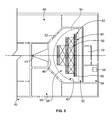
- FIG. 5 is a view taken along line 5 - 5 of FIG. 2 .
- FIG. 6 is a side view of a second embodiment of a new motion simulation theater, with the seats in a boarding position.
- FIG. 7 is a side view of the theater of FIG. 6 , with the seats in a viewing position.
- FIG. 8 is a side view of a third embodiment of a new motion simulation theater, with the seats in a viewing position.
- FIG. 9 is a view taken along line 9 - 9 of FIG. 8 .
- FIG. 10 is a side view of a fourth embodiment of a new motion simulation theater, with the seats in a viewing position.
- FIG. 11 is a view taken along line 11 - 11 of FIG. 10 .
- FIG. 12 is a side view of a fifth embodiment of a new motion simulation theater, with the seats in a boarding position.
- first and second elements refer to a vertical elevation or position, relative to gravity. These terms do not refer to horizontal positions, e.g., a first element may be above or below a second element while the first and second elements are entirely laterally or horizontally spaced apart from each other.
- the term line refers to flexible tensile element, such as a cable, or to a winchable element, such as a chain.
- the term horizontal means perpendicular to the direction of gravity.
- the term attached means attached directly or indirectly through an intermediate element.
- participant and viewer mean the person or persons perceiving one or more sensations provided by the theater.
- program, presentation and media mean prerecorded or stored images displayed in a way perceptible to a viewer, including front or rear projected images, as well as images formed via any type of display (LED, OLED, plasma, hologram, etc.), with or without accompanying sound, scent, physical and/or tactile effects.
- screen also includes these types of displays.
- the terms half or hemi mean one half, or less than half, of a surface curving in three dimensions.
- a motion simulation theater 20 is provided in a building or structure 22 having a screen 54 within a screen room or space 38 .
- a lifting system 26 is supported on or by a ceiling structure 24 of the building 2 .
- the lifting system 26 may include one or more electric motors 28 , gear drives 30 and winch rollers 32 .
- a seating frame 80 is suspended on lines 34 attached to the lifting system, to allow the seating frame 80 to be moved vertically within the theater 20 .
- Seats 88 are attached to or suspended from the frame 80 .
- the seats 88 may be provided in rows 82 .
- the seats 88 may be attached to the frame 80 at a pivot joint 86 via a rigid seat link or armature 84 .
- the seat link 84 is dimensioned so that the nominal sight line 94 of a participant 90 is not blocked by another seat.
- the head of the participant 90 in a back row may be spaced below the feet of a participant in the next forward row by a dimension DD, ranging from about 10 to 150 cm (based on participants of standard height ranges).
- the seating surfaces of seats in adjacent rows may be vertically spaced apart by 200 or 220 cm up to about 300 cm, with the seats in the viewing position BB shown in FIG. 1 .
- One or more projectors 60 are positioned to project images onto the screen.
- Conventional or rear projection projectors may be used. Projectors can be oriented to project images onto the screen or screens to create seamless, edge-blended images. Displays and other image forming techniques may also be used.
- Sound speakers 62 are also provided in the screen room 38 .
- the theater 20 may include surround sound audio components with a multi-channel system including a respective speaker unit on each channel of the system.
- the speaker system typically is placed in a central location, with each speaker unit facing to direct sound output in the respective direction toward an opposed wall surface, with the sound reflecting off the opposed wall.
- An electronic controller 56 for controlling various elements of the theater may be provided in a control room 58 adjacent to the screen room 38 .
- the electronic controller 56 may operate to integrate movement of the passenger seats 88 with action of the media presentation.
- the controller 56 may control operation of the lifting system 26 .
- the controller may operate independently of, but in synchronization with the media presentation.
- the controller 56 may be operatively integrated with the media presentation and operable in response to a signal or signals embedded in the media or transmitted from the projection system.
- the controller may be a microprocessor for which, in either case, the projector or projector system is cued by the microprocessor.
- the electronic control system thus will be synchronized with the sound and the projected media to give the passengers a vivid sensation of being completely immersed in the action on the screen.
- the boarding room 50 includes entry/exit doors 52 , and may also have a pre-show media system, such as a projector 41 and a screen 40 at the front of the boarding room 50 .
- An opening 48 is provided in the floor 46 of the screen room 38 .
- the opening 48 may be generally sized and shaped to match the seating frame 80 , as shown in FIG. 3 .
- a cut-out 42 may be provided in the screen 54 above the opening 48 , to allow the seating frame 80 to pass through from the boarding room 50 into the screen room 38 .
- a movable partial screen 64 may be placed in the cut-out 42 , except during passage of the seating frame 80 , to provide a more expansive surface to form images on, during a presentation.
- the partial screen 64 may be moved out from the cut-out 42 , for example by sliding on a track, by an actuator 65 .
- the seats 88 are spaced up off the floor 72 at about the height of a typical chair, or slightly lower, to allow participants of varying height, including children, to readily seat themselves in the seats 88 .
- the frame 80 may substantially close off the opening 48 . Consequently, the participants 90 cannot then see into the screen room 38 .
- the bottom surface of the frame 80 may be textured and colored to match the rest of the boarding room 50 , so that the participants are not even made aware that the presentation provided in boarding room 50 (if used) is only a prelude to an entirely distinct and more thrilling presentation that follows in the screen room 38 .
- rows 82 of seats 88 are spaced apart front to back sufficiently to allow for easy and rapid movement by participants into and out of the seats. As shown in FIG. 4 , the length of the seat rows 82 may increase towards the back of the theater 20 .
- the seats 88 , or rows of seats 82 are suspended from the frame 80 , which is typically a rigid structure with bracing elements 92 between the rows and elsewhere as may be needed.
- Special effects devices 96 may be provided on the frame 80 or on the seats 88 or seat links 84 .
- the special effects devices 96 may include air movers, air heaters or chillers, scent emitters, water spray, ticklers, shakers, vibrators, etc.
- the seats 88 or seat rows 82 may be attached to the seat links on a pivot joint allowing the seats 88 to be pivoted forwardly or rearward by seat actuators, to provide a sensation of acceleration or deceleration.
- the theater 20 may optionally include a pre-board lobby 66 leading to the entry doors 52 of the boarding room 50 .
- the pre-board lobby main include thematic elements and/or a pre-board live or recorded presentation.
- An exit hall 68 may be provided in the theater opposite from the pre-board lobby, to allow for one way viewer movement through the theater 20 .
- a projection booth 70 may be centrally located at the back of the screen room.
- participant enter the boarding room 50 and sit in a seat 88 .
- the participants secure themselves in place with a seat belt or harness, and/or a restraining bar.
- the electronic controller 56 may provide an indication that all participants are secured in place.
- a presentation may be provided in the boarding room via the projector 41 and screen 40 , and/or via a live host. Alternatively, such a presentation made provided in the pre-board lobby 66 .
- the controller may initiate the main show.
- the partial screen 64 if used, is in the retracted position shown in FIG. 1 .
- the lifting system 26 lifts the frame 80 from position CC shown in FIGS. 2 and 3 , to the viewing of show position BB shown in FIG. 1 .
- the lifting lines 34 lift the frame up. Multiple lifting lines 34 typically are used. This movement may initially be purely vertical movement. The screen room 38 may be dark during this movement. Alternatively, this movement may occur shortly after the presentation is initiated, providing a sensation of launching and upward vertical movement or flying.
- the lifting system 26 is adapted to lift the entire frame up, and also to tilt the frame 80 into the inclined position shown in FIG. 1 .
- the lifting system 26 may achieve the tilt via winching speed obtained by motor control and/or by winch ratios. Consequently, the tilting movement may be continuous and linear from position CC to position BB, or the frame 80 may remain horizontal while it is lifted partially or fully to position BB, with the tilting occurring only after the back end of the frame 80 has reached a final vertical position.
- the tilting movement may occur about an axis TT at the back end of the frame 80 , moving the seats 88 in an arc up and away from the screen 40 .
- the front and any middle lift lines may move rearward on the winches 32 , while the back lift lines 34 remain stationary.
- the seats 88 remain level via the pivot attachment 86 between the seat links 84 and the frame 80 , notwithstanding the tilting of the frame. With the frame angled upwardly in elevation towards the screen as shown at position BB in FIG. 1 , the seats 88 are in a reverse stadium seating configuration (with the highest seats closest to the screen and the lowest seats furthest away from the screen).
- the theater 20 may optionally include a lifting system longitudinal actuator 36 that moves the lifting system 26 in the direction of arrow LA in FIG. 1 . This allows the seats to be moved towards and away from the screen 54 , when the seats are in the viewing position BB.
- the presentation in screen room 38 begins, and only then may the participants realize that they are now in an elevated position and surrounded by images, providing a thrilling and immersive effect.
- the partial screen 64 is moved into the screen cutout 42 .
- the participant's line of sight is substantially surrounded or enveloped by the images on the screen, due to the participant's elevated position.
- Actuators on the seats 88 , seat links 84 or on the frame 80 may provide physical effects such as seat pitch, roll, yaw or heave, similar to motion base movements, in coordination with the images on the screen.
- the lifting system 26 may be actuated during the presentation to accelerate the participants up or down. Since the lifting system can provide a very large range of vertical movements, acceleration effects can be achieved that are not achievable with conventional motion simulation theaters. For example, acceleration may be sustained for longer time intervals in comparison to conventional techniques.
- the lifting system 26 reverses direction and returns the frame 80 back to position CC shown in FIGS. 2 and 3 . This movement may also occur with the screen room and the boarding room dark. With the frame and the seats returned to boarding position, the participants release their seat restraints and exit the theater. The theater 20 is then ready for boarding by a next group of participants.
- FIGS. 6 and 7 show another theater 100 similar to the theater 20 , but with a boarding room 102 above the screen room 38 .
- the boarding room 102 may have a sliding floor 104 moved by a floor actuator 106 .
- the floor actuator 106 retracts the sliding floor 104 .
- the frame 80 is then lowered into the screen room 38 .
- the theater 100 may otherwise operate in the same way as the theater 20 described above.
- the lifting system longitudinal actuator 36 may be used in the theater 100 , in place of the sliding floor 104 .
- the participants or riders board the seats in a boarding room having a fixed floor.
- the seats are then moved into alignment over a cutout or opening at or near the top of the screen room 38 .
- the seats are lowered into the viewing position via the lifting system.
- FIGS. 8 and 9 show another theater 120 which may be the same as the theater 20 , except that a cylindrical screen 122 is used in place of the half-dome screen shown in FIGS. 1 and 2 .
- the half dome screen in FIGS. 1 and 2 may be hemi-spherical, ovoid, elliptical, or have another shape curving in three dimensions, while the screen in FIGS. 8 and 9 curves in two dimensions.
- the angle of the central axis M of the dome screen 54 shown in FIG. 2 may vary with the configuration of the screen room 38 .
- the screen axis angle AH shown in FIG. 2 may typically range from about 35 to 65 degrees.
- the central screen axis AA generally bisects the frame 80 .
- FIG. 10 shows another theater 130 which may be the same as the theater 20 , except that one or more flat screens 132 are used. As shown in FIG. 11 , three flat screens may be joined to each other in essentially a half hexagon shape.
- FIG. 12 shows another embodiment similar to the theater 100 shown in FIGS. 6 and 7 , but with a boarding room 50 above the screen room 38 and a de-boarding exit hall 68 below the screen room. In this design, participants enter at an upper level and exit at a lower level.
- the motion simulation theater 20 is designed and constructed provide a sensory immersion and/or a motion simulation experience to an audience.
- the theater may be designed to create the initial impression to the audience of being in a standard non-motion theater, thus providing an element of surprise when the main screen 54 in the screen room 38 is revealed and the seats 88 begin to rise, creating the sensation of launching into flight.
- the theater may also be adapted to provide synchronized motion of the participants with special effects, including, visceral, tactile and audible sensations which simulate flight through a particular environment, storyline, experience, and/or activity.
Abstract
Description
Claims (19)
Priority Applications (3)
| Application Number | Priority Date | Filing Date | Title |
|---|---|---|---|
| US12/712,606 US8225555B2 (en) | 2010-02-25 | 2010-02-25 | Motion simulator theater with suspended seating |
| PCT/US2011/026011 WO2011106488A1 (en) | 2010-02-25 | 2011-02-24 | Motion simulator theater with suspended seating |
| US13/556,164 US8474191B2 (en) | 2010-02-25 | 2012-07-23 | Motion simulator theater with suspended seating |
Applications Claiming Priority (1)
| Application Number | Priority Date | Filing Date | Title |
|---|---|---|---|
| US12/712,606 US8225555B2 (en) | 2010-02-25 | 2010-02-25 | Motion simulator theater with suspended seating |
Related Child Applications (1)
| Application Number | Title | Priority Date | Filing Date |
|---|---|---|---|
| US13/556,164 Continuation US8474191B2 (en) | 2010-02-25 | 2012-07-23 | Motion simulator theater with suspended seating |
Publications (2)
| Publication Number | Publication Date |
|---|---|
| US20110203190A1 US20110203190A1 (en) | 2011-08-25 |
| US8225555B2 true US8225555B2 (en) | 2012-07-24 |
Family
ID=44475288
Family Applications (2)
| Application Number | Title | Priority Date | Filing Date |
|---|---|---|---|
| US12/712,606 Active 2030-03-19 US8225555B2 (en) | 2010-02-25 | 2010-02-25 | Motion simulator theater with suspended seating |
| US13/556,164 Active US8474191B2 (en) | 2010-02-25 | 2012-07-23 | Motion simulator theater with suspended seating |
Family Applications After (1)
| Application Number | Title | Priority Date | Filing Date |
|---|---|---|---|
| US13/556,164 Active US8474191B2 (en) | 2010-02-25 | 2012-07-23 | Motion simulator theater with suspended seating |
Country Status (2)
| Country | Link |
|---|---|
| US (2) | US8225555B2 (en) |
| WO (1) | WO2011106488A1 (en) |
Cited By (10)
| Publication number | Priority date | Publication date | Assignee | Title |
|---|---|---|---|---|
| US20110170074A1 (en) * | 2009-11-06 | 2011-07-14 | Bran Ferren | System for providing an enhanced immersive display environment |
| WO2014151992A1 (en) * | 2013-03-15 | 2014-09-25 | Oceaneering International, Inc. | Inverted motion base with suspended seating |
| US20150273348A1 (en) * | 2012-10-26 | 2015-10-01 | Dynamic Structures, Ltd. | Flying theatre |
| WO2016186683A1 (en) * | 2015-05-15 | 2016-11-24 | Vision 3 Experiential, Llc | Immersive theater |
| US9643094B2 (en) | 2015-05-05 | 2017-05-09 | Universal City Studios Llc | Simulator ride |
| US10369482B2 (en) * | 2017-04-27 | 2019-08-06 | Universal City Studios Llc | Dome theater ride system and method |
| US10369483B1 (en) | 2018-01-23 | 2019-08-06 | Universal City Studios Llc | Interactive tower attraction systems and methods |
| US10398989B2 (en) | 2018-01-29 | 2019-09-03 | Universal City Studios Llc | Ride with rotating lift |
| WO2019217585A1 (en) * | 2018-05-08 | 2019-11-14 | Wartsila North America, Inc. | Raiseable theater seating system for amusement ride |
| US11338214B2 (en) | 2020-04-27 | 2022-05-24 | Universal City Studios Llc | Dark ride tower systems having stationary and adaptable rooms |
Families Citing this family (16)
| Publication number | Priority date | Publication date | Assignee | Title |
|---|---|---|---|---|
| WO2013106243A1 (en) * | 2012-01-12 | 2013-07-18 | West Kanye Omari | Multiple screens for immersive audio/video experience |
| EP2626485A1 (en) * | 2012-02-03 | 2013-08-14 | INTER+-POL Freie Forschungs- u. Entwicklungsges. f. unfassb. Formate, exper. Proj.,ungesehene Filme dicke u. dünne Bücher, grenzenl. Räume, ....mbH | Tribune |
| CN102728075B (en) * | 2012-05-23 | 2014-08-27 | 宁波新文三维股份有限公司 | Flying cinema device |
| AT513435B1 (en) * | 2012-09-21 | 2015-02-15 | Valtiner & Partner Zt Gmbh | Entertainment device |
| CN103089036B (en) * | 2013-01-05 | 2015-09-09 | 深圳华侨城文化旅游科技股份有限公司 | A kind of Prostration type watch-film system and its implementation |
| CN103061546A (en) * | 2013-02-06 | 2013-04-24 | 山东华夏集团有限公司 | Large-sized live-action performance theatre |
| CN103309328B (en) * | 2013-06-07 | 2016-06-22 | 上海德理孚自动化系统有限公司 | Distributed sport simulated system and control method thereof |
| CN104278859B (en) * | 2013-07-03 | 2017-04-12 | 北京秀域科技文化股份有限公司 | Pod type auditorium facility capable of moving in multiple dimensions |
| CN103628706B (en) * | 2013-11-13 | 2015-08-26 | 芜湖华强文化科技产业有限公司 | A kind of can three grades lifting stages |
| CN103953207B (en) * | 2014-04-25 | 2016-04-06 | 温州南方游乐设备工程有限公司 | A kind of ball screen cinema rotates viewing platform |
| CN104196282A (en) * | 2014-09-18 | 2014-12-10 | 江苏卡罗卡国际动漫城有限公司 | Dynamic riding equipment for fulldome theaters |
| CN204343720U (en) * | 2014-12-09 | 2015-05-20 | 深圳华侨城文化旅游科技有限公司 | A kind of dynamic multi-faceted viewing system |
| CN108211384A (en) * | 2016-12-12 | 2018-06-29 | 北京以诺视景科技有限公司 | Flight film and drama field |
| WO2019092402A1 (en) * | 2017-11-09 | 2019-05-16 | Holovis International Limited | A flying theatre system |
| WO2019203588A1 (en) * | 2018-04-18 | 2019-10-24 | Cj 4Dplex Co., Ltd. | Theater having mezzanine floor structure equipped with motion chairs |
| AU2020271548A1 (en) * | 2019-04-11 | 2021-11-04 | Oceaneering International, Inc. | Suspended theater edge actuated seat moving machine |
Citations (32)
| Publication number | Priority date | Publication date | Assignee | Title |
|---|---|---|---|---|
| US1005061A (en) | 1911-01-21 | 1911-10-03 | Robert Macfarlane Murie | Amusement apparatus. |
| US1388130A (en) | 1919-10-29 | 1921-08-16 | Selene P Thompson | Amusement apparatus |
| US1781058A (en) | 1929-07-20 | 1930-11-11 | Spalding & Bros Ag | Movable bleacher |
| US1845008A (en) | 1930-12-24 | 1932-02-16 | Kelly Springfield Tire Company | Shoe sole |
| US1849052A (en) | 1930-01-21 | 1932-03-08 | Walter C Urling | Adjustable audience seat |
| US1974035A (en) | 1932-12-14 | 1934-09-18 | James H Adamson | Audience seat |
| US2076113A (en) | 1934-11-26 | 1937-04-06 | John N Bartlett | Amusement ride |
| US2590934A (en) | 1949-08-26 | 1952-04-01 | William G Catlett | Portable ferris wheel |
| US3628829A (en) | 1966-03-09 | 1971-12-21 | Morton L Heilig | Experience theater |
| US3661279A (en) | 1969-06-11 | 1972-05-09 | Krupp Gmbh | Device for transloading floating containers |
| US3707282A (en) | 1970-02-05 | 1972-12-26 | Le Roy A Anderson | Planetary amusement ride |
| US3868107A (en) | 1972-02-28 | 1975-02-25 | Taketoshi Ichida | Simulated viewing apparatus |
| US4642945A (en) | 1984-07-03 | 1987-02-17 | Cinemotion Pty. Ltd. | Entertainment structure |
| US4879849A (en) | 1987-11-04 | 1989-11-14 | Omni Films International, Inc. | Point-of-view motion simulator system |
| US4976438A (en) | 1989-03-14 | 1990-12-11 | Namco Ltd. | Multi-player type video game playing system |
| US5021954A (en) | 1988-01-11 | 1991-06-04 | The Walt Disney Company | System and method of providing passenger ingress and egress in an amusement ride |
| US5161104A (en) | 1988-01-11 | 1992-11-03 | The Walt Disney Company | Amusement ride having pivotable ingress-egress bridges |
| US5192247A (en) | 1991-03-27 | 1993-03-09 | Universal City Studios, Inc. | Ride attraction |
| US5224425A (en) | 1991-06-12 | 1993-07-06 | Bruce Remington | Cable skydiving |
| US5433670A (en) | 1993-02-05 | 1995-07-18 | Ridefilm Corporation | Compact simulator system theater |
| US5453011A (en) | 1993-06-10 | 1995-09-26 | Feuer; Eduard | Flight simulator |
| US5611174A (en) | 1994-06-24 | 1997-03-18 | Hayashi; Masahiko | Dome theater |
| US5660000A (en) | 1996-08-09 | 1997-08-26 | Macintyre; James R. | Movable two-fold seating assembly |
| US5791903A (en) | 1993-06-10 | 1998-08-11 | Fir Ride & Show Engineering, Inc. | Flight simulator with full roll rotation capability |
| US5803816A (en) | 1994-10-19 | 1998-09-08 | Soriani & Moser | Amusement ride |
| US5845434A (en) | 1995-10-23 | 1998-12-08 | Hayashi; Masahiko | Theatre |
| US5947828A (en) | 1996-01-30 | 1999-09-07 | Far Fabbri S.R.L. | Ride for fun fairs |
| US6053576A (en) | 1998-10-30 | 2000-04-25 | Jessee; Michael J | Bank of seats for amusement ride |
| US6354954B1 (en) | 2000-12-28 | 2002-03-12 | Disney Enterprises, Inc. | Amusement apparatus and method |
| US6727971B2 (en) | 2001-01-05 | 2004-04-27 | Disney Enterprises, Inc. | Apparatus and method for curved screen projection |
| US20050014567A1 (en) | 2003-04-15 | 2005-01-20 | Ming Li | Amusement apparatus and method |
| US20070193123A1 (en) | 2006-02-23 | 2007-08-23 | Magpuri Cecil D | Circular motion theater |
Family Cites Families (3)
| Publication number | Priority date | Publication date | Assignee | Title |
|---|---|---|---|---|
| US845008A (en) * | 1906-04-10 | 1907-02-19 | Albert O Ewers | Seat-removing apparatus. |
| FR1054244A (en) * | 1951-12-18 | 1954-02-09 | Applic Mach Motrices | Shooting training device for pilots of fixed-weapon aircraft |
| US5282772A (en) * | 1991-10-17 | 1994-02-01 | Mitsubishi Jukogyo Kabushiki Kaisha | Simulator for shooting down the rapids |
-
2010
- 2010-02-25 US US12/712,606 patent/US8225555B2/en active Active
-
2011
- 2011-02-24 WO PCT/US2011/026011 patent/WO2011106488A1/en active Application Filing
-
2012
- 2012-07-23 US US13/556,164 patent/US8474191B2/en active Active
Patent Citations (33)
| Publication number | Priority date | Publication date | Assignee | Title |
|---|---|---|---|---|
| US1005061A (en) | 1911-01-21 | 1911-10-03 | Robert Macfarlane Murie | Amusement apparatus. |
| US1388130A (en) | 1919-10-29 | 1921-08-16 | Selene P Thompson | Amusement apparatus |
| US1781058A (en) | 1929-07-20 | 1930-11-11 | Spalding & Bros Ag | Movable bleacher |
| US1849052A (en) | 1930-01-21 | 1932-03-08 | Walter C Urling | Adjustable audience seat |
| US1845008A (en) | 1930-12-24 | 1932-02-16 | Kelly Springfield Tire Company | Shoe sole |
| US1974035A (en) | 1932-12-14 | 1934-09-18 | James H Adamson | Audience seat |
| US2076113A (en) | 1934-11-26 | 1937-04-06 | John N Bartlett | Amusement ride |
| US2590934A (en) | 1949-08-26 | 1952-04-01 | William G Catlett | Portable ferris wheel |
| US3628829A (en) | 1966-03-09 | 1971-12-21 | Morton L Heilig | Experience theater |
| US3661279A (en) | 1969-06-11 | 1972-05-09 | Krupp Gmbh | Device for transloading floating containers |
| US3707282A (en) | 1970-02-05 | 1972-12-26 | Le Roy A Anderson | Planetary amusement ride |
| US3868107A (en) | 1972-02-28 | 1975-02-25 | Taketoshi Ichida | Simulated viewing apparatus |
| US4642945A (en) | 1984-07-03 | 1987-02-17 | Cinemotion Pty. Ltd. | Entertainment structure |
| US4879849A (en) | 1987-11-04 | 1989-11-14 | Omni Films International, Inc. | Point-of-view motion simulator system |
| US5161104A (en) | 1988-01-11 | 1992-11-03 | The Walt Disney Company | Amusement ride having pivotable ingress-egress bridges |
| US5277662A (en) | 1988-01-11 | 1994-01-11 | The Walt Disney Company | System and method of providing passenger ingress and egress in an amusement ride having pivotable bridges |
| US5021954A (en) | 1988-01-11 | 1991-06-04 | The Walt Disney Company | System and method of providing passenger ingress and egress in an amusement ride |
| US4976438A (en) | 1989-03-14 | 1990-12-11 | Namco Ltd. | Multi-player type video game playing system |
| US5192247A (en) | 1991-03-27 | 1993-03-09 | Universal City Studios, Inc. | Ride attraction |
| US5224425A (en) | 1991-06-12 | 1993-07-06 | Bruce Remington | Cable skydiving |
| US5433670A (en) | 1993-02-05 | 1995-07-18 | Ridefilm Corporation | Compact simulator system theater |
| US5453011A (en) | 1993-06-10 | 1995-09-26 | Feuer; Eduard | Flight simulator |
| US5791903A (en) | 1993-06-10 | 1998-08-11 | Fir Ride & Show Engineering, Inc. | Flight simulator with full roll rotation capability |
| US5611174A (en) | 1994-06-24 | 1997-03-18 | Hayashi; Masahiko | Dome theater |
| US5803816A (en) | 1994-10-19 | 1998-09-08 | Soriani & Moser | Amusement ride |
| US5845434A (en) | 1995-10-23 | 1998-12-08 | Hayashi; Masahiko | Theatre |
| US5947828A (en) | 1996-01-30 | 1999-09-07 | Far Fabbri S.R.L. | Ride for fun fairs |
| US5660000A (en) | 1996-08-09 | 1997-08-26 | Macintyre; James R. | Movable two-fold seating assembly |
| US6053576A (en) | 1998-10-30 | 2000-04-25 | Jessee; Michael J | Bank of seats for amusement ride |
| US6354954B1 (en) | 2000-12-28 | 2002-03-12 | Disney Enterprises, Inc. | Amusement apparatus and method |
| US6727971B2 (en) | 2001-01-05 | 2004-04-27 | Disney Enterprises, Inc. | Apparatus and method for curved screen projection |
| US20050014567A1 (en) | 2003-04-15 | 2005-01-20 | Ming Li | Amusement apparatus and method |
| US20070193123A1 (en) | 2006-02-23 | 2007-08-23 | Magpuri Cecil D | Circular motion theater |
Non-Patent Citations (1)
| Title |
|---|
| United States Patent and Trademark Office, Search Report and Written Opinion for PCT/US11/26011, mailed Apr. 19, 2011. |
Cited By (21)
| Publication number | Priority date | Publication date | Assignee | Title |
|---|---|---|---|---|
| US9465283B2 (en) * | 2009-11-06 | 2016-10-11 | Applied Minds, Llc | System for providing an enhanced immersive display environment |
| US20110170074A1 (en) * | 2009-11-06 | 2011-07-14 | Bran Ferren | System for providing an enhanced immersive display environment |
| US20150273348A1 (en) * | 2012-10-26 | 2015-10-01 | Dynamic Structures, Ltd. | Flying theatre |
| US9463391B2 (en) * | 2012-10-26 | 2016-10-11 | Dynamic Structures, Ltd. | Flying theatre |
| WO2014151992A1 (en) * | 2013-03-15 | 2014-09-25 | Oceaneering International, Inc. | Inverted motion base with suspended seating |
| US9254040B2 (en) | 2013-03-15 | 2016-02-09 | Oceaneering International, Inc. | Inverted motion base with suspended seating |
| EP2967216A4 (en) * | 2013-03-15 | 2016-11-30 | Oceaneering Int Inc | Inverted motion base with suspended seating |
| US10500507B2 (en) | 2015-05-05 | 2019-12-10 | Universal City Studios Llc | Simulator ride |
| US9643094B2 (en) | 2015-05-05 | 2017-05-09 | Universal City Studios Llc | Simulator ride |
| WO2016186683A1 (en) * | 2015-05-15 | 2016-11-24 | Vision 3 Experiential, Llc | Immersive theater |
| US9523209B2 (en) | 2015-05-15 | 2016-12-20 | Vision 3 Experiential, Llc | Immersive theater |
| US10369482B2 (en) * | 2017-04-27 | 2019-08-06 | Universal City Studios Llc | Dome theater ride system and method |
| US10369483B1 (en) | 2018-01-23 | 2019-08-06 | Universal City Studios Llc | Interactive tower attraction systems and methods |
| US10843092B2 (en) | 2018-01-23 | 2020-11-24 | Universal City Studios Llc | Interactive tower attraction systems and methods |
| US11192041B2 (en) | 2018-01-23 | 2021-12-07 | Universal City Studios Llc | Interactive tower attraction systems and methods |
| US11666833B2 (en) | 2018-01-23 | 2023-06-06 | Universal City Studios Llc | Interactive tower attraction systems and methods |
| US10398989B2 (en) | 2018-01-29 | 2019-09-03 | Universal City Studios Llc | Ride with rotating lift |
| US10821368B2 (en) | 2018-01-29 | 2020-11-03 | Universal City Studio LLC | Ride with rotating lift |
| US11395976B2 (en) | 2018-01-29 | 2022-07-26 | Universal City Studios Llc | Ride with rotating lift |
| WO2019217585A1 (en) * | 2018-05-08 | 2019-11-14 | Wartsila North America, Inc. | Raiseable theater seating system for amusement ride |
| US11338214B2 (en) | 2020-04-27 | 2022-05-24 | Universal City Studios Llc | Dark ride tower systems having stationary and adaptable rooms |
Also Published As
| Publication number | Publication date |
|---|---|
| US20120317889A1 (en) | 2012-12-20 |
| US20110203190A1 (en) | 2011-08-25 |
| US8474191B2 (en) | 2013-07-02 |
| WO2011106488A1 (en) | 2011-09-01 |
Similar Documents
| Publication | Publication Date | Title |
|---|---|---|
| US8225555B2 (en) | Motion simulator theater with suspended seating | |
| US9540832B2 (en) | Circular motion theater | |
| US10398990B2 (en) | Rotating performance stage | |
| US20100300006A1 (en) | Virtual reality dome theater | |
| US20050014567A1 (en) | Amusement apparatus and method | |
| US5192247A (en) | Ride attraction | |
| US9266028B2 (en) | Tower ride | |
| US9155390B2 (en) | Presentation viewing apparatus and method | |
| US6076638A (en) | Special effects elevator | |
| DK2795401T3 (en) | Film display device and method for displaying a film | |
| EP3231963B1 (en) | Dynamic multidirectional film watching system | |
| US5556340A (en) | Amusement ride assembly with rotating tube synchronized with an image | |
| JP2013226231A (en) | Play equipment equipped with dome screen | |
| JPH05200163A (en) | Vehicle-simulation amusing apparatus | |
| JP2009254731A (en) | Flight simulation experience amusement apparatus | |
| JPH086486A (en) | Water surface oscillation simulator | |
| JP2019107107A (en) | Game device and game facility | |
| JPH03162888A (en) | Rocking device for play | |
| JP2005305108A (en) | Attraction system | |
| KR20190121704A (en) | A theater comprising motion-enabled chair | |
| EP3470126A1 (en) | Kinesthetic device with different seating orientations |
Legal Events
| Date | Code | Title | Description |
|---|---|---|---|
| AS | Assignment |
Owner name: FALCON'S TREEHOUSE, L.L.C., FLORIDA Free format text: ASSIGNMENT OF ASSIGNORS INTEREST;ASSIGNOR:MAGPURI, CECIL D.;REEL/FRAME:023991/0695 Effective date: 20100225 |
|
| STCF | Information on status: patent grant |
Free format text: PATENTED CASE |
|
| FPAY | Fee payment |
Year of fee payment: 4 |
|
| MAFP | Maintenance fee payment |
Free format text: PAYMENT OF MAINTENANCE FEE, 8TH YR, SMALL ENTITY (ORIGINAL EVENT CODE: M2552); ENTITY STATUS OF PATENT OWNER: SMALL ENTITY Year of fee payment: 8 |
|
| AS | Assignment |
Owner name: FALCON'S BEYOND BRANDS, LLC, FLORIDA Free format text: ASSIGNMENT OF ASSIGNORS INTEREST;ASSIGNOR:FALCON'S BEYOND GLOBAL, LLC;REEL/FRAME:064911/0387 Effective date: 20230627 Owner name: FALCON'S BEYOND GLOBAL,LLC, FLORIDA Free format text: ASSIGNMENT OF ASSIGNORS INTEREST;ASSIGNOR:FALCON'S CREATIVE GROUP, LLC;REEL/FRAME:064911/0188 Effective date: 20230627 Owner name: FALCON'S CREATIVE GROUP, LLC, FLORIDA Free format text: ASSIGNMENT OF ASSIGNORS INTEREST;ASSIGNOR:FALCON'S TREEHOUSE, LLC;REEL/FRAME:064910/0993 Effective date: 20230627 |
|
| MAFP | Maintenance fee payment |
Free format text: PAYMENT OF MAINTENANCE FEE, 12TH YR, SMALL ENTITY (ORIGINAL EVENT CODE: M2553); ENTITY STATUS OF PATENT OWNER: SMALL ENTITY Year of fee payment: 12 |