US7907150B2 - Method of fusion or merging imagery data for improved visual perception using monoscopic and stereographic fusion and retinal decay techniques - Google Patents
Method of fusion or merging imagery data for improved visual perception using monoscopic and stereographic fusion and retinal decay techniques Download PDFInfo
- Publication number
- US7907150B2 US7907150B2 US10/914,376 US91437604A US7907150B2 US 7907150 B2 US7907150 B2 US 7907150B2 US 91437604 A US91437604 A US 91437604A US 7907150 B2 US7907150 B2 US 7907150B2
- Authority
- US
- United States
- Prior art keywords
- image
- black
- fusion
- images
- eye
- Prior art date
- Legal status (The legal status is an assumption and is not a legal conclusion. Google has not performed a legal analysis and makes no representation as to the accuracy of the status listed.)
- Expired - Fee Related, expires
Links
Images


Classifications
-
- H—ELECTRICITY
- H04—ELECTRIC COMMUNICATION TECHNIQUE
- H04N—PICTORIAL COMMUNICATION, e.g. TELEVISION
- H04N13/00—Stereoscopic video systems; Multi-view video systems; Details thereof
- H04N13/30—Image reproducers
- H04N13/332—Displays for viewing with the aid of special glasses or head-mounted displays [HMD]
- H04N13/341—Displays for viewing with the aid of special glasses or head-mounted displays [HMD] using temporal multiplexing
-
- H—ELECTRICITY
- H04—ELECTRIC COMMUNICATION TECHNIQUE
- H04N—PICTORIAL COMMUNICATION, e.g. TELEVISION
- H04N5/00—Details of television systems
- H04N5/30—Transforming light or analogous information into electric information
- H04N5/33—Transforming infrared radiation
Definitions
- the present invention relates to methods of enhancing the perception of images derived from multiple image sensors.
- An object of the present invention achieved by the monoscopic and or stereoscopic display of visual images combined from multiple sources (2 or more) by alternating the exposure of each source image and inserting a null image or black frame between each image frame. This can be done stereoscopically by alternating the eyes and black so that only one view is seen at a time. This can also be done monoscopically by alternating black between a succession of multiple images with that are only approximately registered.
- Another objective of the invention is achieved by presenting a first image frame from a first source to the right eye while a null image or black frame is presented to the left eye. This is followed by presenting either a first or sequential image frame of second image source to the left eye source while the null image or black frame is presented to the right eye, with the sequence repeating to achieve retinal decay.
- Another objective of the invention is achieved by using a stereoscopic display to fuse images from 2 or more non-registered datasets that are loosely registered, but from vastly different image sources. In this instance, insertion of black is not required, but would improve the results.
- Another objective of the invention is achieved by presenting the alternative sources at frame rate of at least about 80 Hz.
- FIG. 1 is a schematic diagram showing an image collection and display system according to the teachings of the instant invention.
- FIG. 2 a schematic diagram showing the desired fusion image as perceived by the viewer.
- FIGS. 3 through 6 are schematic timing charts illustrating a variety of alternative embodiments of the operative principles of image processor P in FIG. 1 for presenting sequential frame of the imaging data in a manner that enables visual fusion by the viewer.
- FIG. 7 is a schematic diagram illustrating one embodiment for implementing the timing diagrams of FIG. 3 to 6 with a single monitor and stereoscopic display.
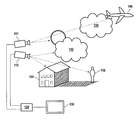
- FIG. 1 is a schematic illustration of an image acquisition and display system 100 according to the teachings of the instant invention.
- Image acquisition cameras 111 and 112 are directed at a common an area of interest, represented by the icon collection 150 .
- At least one of image acquisition cameras can include a non-visual sensor for creating an electronic image that has the potential to reveal objects that would not be visually observed, for example a thermal or infrared imaging camera for detecting people or vehicles at night or obscured by fog, etc.
- the electronic signals corresponding to time sequential images or image frame are conveyed via circuits 115 and 116 to image display control unit 120 .
- Image display control unit 120 comprises an amplifier (A) and an image processor (P).
- the processor combines and transmits the image frames from cameras 111 and 112 to display monitor 130 according to the methods taught herein. This includes:
- the display monitor also includes head mounted goggles where each eye is exposed to a different individual image display monitor for stereoscopic viewing.
- stereoscopic viewing can also be implemented on a single monitor with a sufficiently high refresh or display rate.
- multiple frames can be displayed wherein the viewer uses a binocular stereoscopic optic system to combine images.
- display monitor is used herein to denote the display system component for producing the final visual image detected by the user.
- FIG. 1 illustrates the use of multiple imaging systems to produce the single image in FIG. 2 , representing the desired perception of the image by the viewer who could not perceive the same image if located in the position of the image acquisition cameras.
- dashed lines represent the icons that are detected, that is images by the respective cameras.
- camera 112 is an ordinary video imaging camera it images house 151 , but not person 152 who could be obscured by rain or fog, or be in the deep shadow of house 151 . Further, while camera 112 would perceive clouds 153 or 155 it may not detect airplane 156 flying within the clouds.
- camera 111 is an infrared or thermal imaging camera, i.e.
- image fusion is greatly enhanced by avoiding the over stimulation of the non-attentive neurological functions of the human optical system.
- the multiple images can be properly fused when presented at an appropriate frame rate and by providing a black field between the presentations of the different sources. This is preferably accomplished by alternating the presentation of a different source to each eye while the other eye is presented with the black field.
- FIG. 3 M (monoscopic) describes several sequences for monoscopic fusion:
- FIG. 3 S illustrates the operative principles of image processor P for the time-sequenced presentation of images from cameras 111 and 112 on a frame-by-frame basis that enables fusion according to the aforementioned principles.
- Each row in the table sets forth the image frames presented to the right and left for the elapsed time between successive rows as denoted in the first column.
- the left eye is exposed to the first frame from camera 111
- the right eye is exposed to a null or black image.
- the second 12.5 msec. increment that is 12.5 to 25 msec.
- the right eye is exposed to the first frame from camera 112
- the left eye is exposed to a null or black image.
- the same sequence repeats for the second frame acquired by camera 111 and 112 , such that (1) from 25 to 37.5 the left eye is exposed to the second frame from camera 111 , while the right eye is exposed to a null or black image; and (2) from 37.5 to 50 msec. the right eye is exposed to the first frame from camera 112 , while the left eye is exposed to a null or black image.
- the processor operating in accordance with the timing diagram of FIG. 3 preferably has the capability to store image frames and modify the display refresh rate of analog or digital camera sources as to display the respective images as set forth in FIG. 3 .
- the more preferred rate of presenting null or black frames is greater than about 100 Hz, and most preferably greater than about 120 Hz.
- the image processor has a variable rate of black frame insertion to accommodate this range.
- the processor need not store images, but simply redisplay the images at the ordinary transmission rate, that is the rate designed for the camera, while the processor or other device inserts null or blank images in between alternating views at the preferred rate. As shown in FIG.
- image frames are acquired at 80 Hz. they can be displayed at the same rate so that an image frame need not be stored in a buffer, as the frames are never repeated, the change in image content should be negligible.
- the camera acquisition rate is higher than the rate at which black frames are inserted, then multiple image frames can be presented to one eye in sequence.
- Another alternative, shown in FIG. 6 is to increase the rate at which blank frames are inserted, for examples to 120 Hz, in synchronization with the video acquisition rate.
- FIG. 7 illustrates a preferred embodiment of applying the teachings of FIGS. 4 to 6 for stereoscopic viewing from a single monitor.
- the user wears optical shutter glasses 710 .
- the use and function of optical shutter glasses for stereoscopic or 3-dimensional viewing are further described in U.S. Pat. Nos. 4,884,876 and 5,510,832, which are incorporated herein by reference.
- Optical shutters 710 R and 710 L alternate between opaque and transparent states but 180 degrees out of phase. Briefly, during time frame T 1 , the right eye is presented with a dark field as shutter 710 R closes, that is, transforms from transparent to opaque, in synchronization with monitor 720 displaying the image from camera 111 , which is now visible only to the left eye.
- the left eye is presented with a dark field as shutter 710 L closes, that is, transforms from transparent to opaque, in synchronization with monitor 720 displaying the image from camera 112 , which is now visible only to the right eye. Accordingly, the viewer will now perceive the imaging sources as a combined three dimensional view as the insertion of the null or black frame after the presentation of each source apparently facilitates the natural processes of depth perception inherent in the pre-attentive phase of human vision but without limitations encountered in the prior art.
- the image acquisition cameras need overlap to image the same field for registration of a fused image.
- Image acquisition cameras are preferably separated to increase the stereographic projection of the overlapping viewing fields.
- one camera might view people above the horizon to observe non-visual information at a particular wavelength, where another camera having a different wavelength range of sensitivity views below the horizon such that the fusion of adjacent fields creates a normal or full field view in which the viewer can correlate objects in the sky with ground positions.
- the multiple images can be created from a 3-dimension or stereoscopic image.
- at least one of the image sources is a synthetic image created from electro-magnetic, mechanical or thermal transducers, such as radar, sonar, x-ray, ultrasound, NMR, PET systems and the like.
Abstract
Description
-
- 1. Alternating between
cameras - 2. Insertion of black between the sequence of frames;
- 3. Use of stereo displays to converge and fuse two non-congruent cameras such as thermal and video. These can be autostereo, anaglyph, shutter glasses, HUD, HMD, projection or other stereoscopic display technique;
- 4. Stereoscopic techniques to provide for one eye seeing an image while the other eye sees a null frame of black and switching the signals with at least 85 Hertz;
- 5. Use of the any combination of categories of images such as video, film, sonar, raster images, thermal, multi-spectral, black and white, color or other visual sensor and raster image. Displays can be monoscopic or stereoscopic.
- 1. Alternating between
-
- a) alternating between
cameras 111, 112 (or more) at frequencies higher than 85 hertz; - b) insertion of black between frames;
- c)
multiple cameras
- a) alternating between
Claims (13)
Priority Applications (1)
| Application Number | Priority Date | Filing Date | Title |
|---|---|---|---|
| US10/914,376 US7907150B2 (en) | 2003-08-09 | 2004-08-09 | Method of fusion or merging imagery data for improved visual perception using monoscopic and stereographic fusion and retinal decay techniques |
Applications Claiming Priority (2)
| Application Number | Priority Date | Filing Date | Title |
|---|---|---|---|
| US49357803P | 2003-08-09 | 2003-08-09 | |
| US10/914,376 US7907150B2 (en) | 2003-08-09 | 2004-08-09 | Method of fusion or merging imagery data for improved visual perception using monoscopic and stereographic fusion and retinal decay techniques |
Publications (2)
| Publication Number | Publication Date |
|---|---|
| US20050128584A1 US20050128584A1 (en) | 2005-06-16 |
| US7907150B2 true US7907150B2 (en) | 2011-03-15 |
Family
ID=34656929
Family Applications (1)
| Application Number | Title | Priority Date | Filing Date |
|---|---|---|---|
| US10/914,376 Expired - Fee Related US7907150B2 (en) | 2003-08-09 | 2004-08-09 | Method of fusion or merging imagery data for improved visual perception using monoscopic and stereographic fusion and retinal decay techniques |
Country Status (1)
| Country | Link |
|---|---|
| US (1) | US7907150B2 (en) |
Cited By (3)
| Publication number | Priority date | Publication date | Assignee | Title |
|---|---|---|---|---|
| US20090207238A1 (en) * | 2008-02-20 | 2009-08-20 | Samsung Electronics Co., Ltd. | Method and apparatus for determining view of stereoscopic image for stereo synchronization |
| US20120050263A1 (en) * | 2010-08-24 | 2012-03-01 | Samsung Electronics Co., Ltd. | 3d image processing apparatus and method for processing 3d images |
| US20180218211A1 (en) * | 2015-08-11 | 2018-08-02 | Sony Interactive Entertainment Inc. | Head-mounted display |
Families Citing this family (19)
| Publication number | Priority date | Publication date | Assignee | Title |
|---|---|---|---|---|
| JP4448039B2 (en) * | 2005-01-26 | 2010-04-07 | キヤノン株式会社 | Imaging apparatus and control method thereof |
| JP2006333133A (en) * | 2005-05-26 | 2006-12-07 | Sony Corp | Imaging apparatus and method, program, program recording medium and imaging system |
| US8274553B2 (en) * | 2005-10-18 | 2012-09-25 | Texas Instruments Incorporated | System and method for displaying stereoscopic digital motion picture images |
| KR100893616B1 (en) * | 2006-04-17 | 2009-04-20 | 삼성모바일디스플레이주식회사 | Electronic imaging device, 2d/3d image display device and the driving method thereof |
| KR101309793B1 (en) * | 2007-01-12 | 2013-09-23 | 삼성전자주식회사 | The image apparatus of processing stereography image and method thereof |
| EP2001235B1 (en) * | 2007-06-08 | 2013-05-22 | Samsung Electronics Co., Ltd. | MPEG-4 format extension for recording stereoscopic or synthetic 3D video data with related metadata |
| US8482613B2 (en) * | 2007-09-10 | 2013-07-09 | John Kempf | Apparatus and method for photographing birds |
| KR101599848B1 (en) * | 2008-11-18 | 2016-03-07 | 엘지전자 주식회사 | 3-dimensional display and method for driving the same |
| KR101545510B1 (en) * | 2008-12-24 | 2015-08-20 | 삼성전자주식회사 | 2 3 Method and apparatus for displaying 2-dimensional image sequence or 3-dimensional image sequence with frame rate adjustment |
| JP5469911B2 (en) * | 2009-04-22 | 2014-04-16 | ソニー株式会社 | Transmitting apparatus and stereoscopic image data transmitting method |
| JP5285517B2 (en) * | 2009-06-30 | 2013-09-11 | パナソニック株式会社 | Video signal processing apparatus, video processing system, semiconductor integrated circuit, and video signal processing method |
| US20110141230A1 (en) * | 2009-12-16 | 2011-06-16 | Samsung Electronics Co., Ltd. | 3d display device and method for correcting image thereof |
| KR20110068396A (en) * | 2009-12-16 | 2011-06-22 | 삼성전자주식회사 | Display device and method for displaying thereof |
| US20110216173A1 (en) * | 2010-03-02 | 2011-09-08 | Comcast Cable Communications, Llc | Impairments To 3D Experiences |
| US20130010085A1 (en) * | 2010-03-16 | 2013-01-10 | Yoshiki Takata | Three-dimensional image display device, three-dimensional imaging device, television receiver, game device, recording medium, and method of transmitting three-dimensional image |
| KR101289654B1 (en) * | 2010-05-07 | 2013-07-25 | 엘지디스플레이 주식회사 | Image display device and driving method thereof |
| US20120098971A1 (en) * | 2010-10-22 | 2012-04-26 | Flir Systems, Inc. | Infrared binocular system with dual diopter adjustment |
| CN103595995B (en) * | 2013-11-13 | 2015-09-09 | 京东方科技集团股份有限公司 | A kind of processing method, Apparatus and system of shutter type three-dimensional image display |
| CN109003228B (en) * | 2018-07-16 | 2023-06-13 | 杭州电子科技大学 | Dark field microscopic large-view-field automatic stitching imaging method |
Citations (14)
| Publication number | Priority date | Publication date | Assignee | Title |
|---|---|---|---|---|
| US4792850A (en) * | 1987-11-25 | 1988-12-20 | Sterographics Corporation | Method and system employing a push-pull liquid crystal modulator |
| US4843460A (en) * | 1986-10-20 | 1989-06-27 | Etat Francais | Electro- optical device and process for real time measurement of the motion of a mobile rigid structure under the influence of a fluid |
| US5416510A (en) * | 1991-08-28 | 1995-05-16 | Stereographics Corporation | Camera controller for stereoscopic video system |
| US5726703A (en) * | 1995-07-14 | 1998-03-10 | Pioneer Electronic Corporation | Stereoscopic image display system |
| US5930037A (en) * | 1996-04-30 | 1999-07-27 | Nec Corporation | Stereoscopic display apparatus which prevents inverse stereoscopic vision |
| US6023277A (en) * | 1996-07-03 | 2000-02-08 | Canon Kabushiki Kaisha | Display control apparatus and method |
| US6111582A (en) * | 1996-12-20 | 2000-08-29 | Jenkins; Barry L. | System and method of image generation and encoding using primitive reprojection |
| US6163336A (en) * | 1994-12-13 | 2000-12-19 | Richards; Angus Duncan | Tracking system for stereoscopic display systems |
| US20020122113A1 (en) * | 1999-08-09 | 2002-09-05 | Foote Jonathan T. | Method and system for compensating for parallax in multiple camera systems |
| US6532008B1 (en) * | 2000-03-13 | 2003-03-11 | Recherches Point Lab Inc. | Method and apparatus for eliminating steroscopic cross images |
| US20030048354A1 (en) * | 2001-08-29 | 2003-03-13 | Sanyo Electric Co., Ltd. | Stereoscopic image processing and display system |
| US6853357B2 (en) * | 2000-08-11 | 2005-02-08 | Canon Kabushiki Kaisha | Image display apparatus and method, and storage medium |
| US20050057580A1 (en) * | 2001-09-25 | 2005-03-17 | Atsuhiro Yamano | El display panel and el display apparatus comprising it |
| US20070146251A1 (en) * | 2001-07-09 | 2007-06-28 | Matsushita Electric Industrial Co., Ltd. | EL display apparatus, driving circuit of EL display apparatus, and image display apparatus |
-
2004
- 2004-08-09 US US10/914,376 patent/US7907150B2/en not_active Expired - Fee Related
Patent Citations (14)
| Publication number | Priority date | Publication date | Assignee | Title |
|---|---|---|---|---|
| US4843460A (en) * | 1986-10-20 | 1989-06-27 | Etat Francais | Electro- optical device and process for real time measurement of the motion of a mobile rigid structure under the influence of a fluid |
| US4792850A (en) * | 1987-11-25 | 1988-12-20 | Sterographics Corporation | Method and system employing a push-pull liquid crystal modulator |
| US5416510A (en) * | 1991-08-28 | 1995-05-16 | Stereographics Corporation | Camera controller for stereoscopic video system |
| US6163336A (en) * | 1994-12-13 | 2000-12-19 | Richards; Angus Duncan | Tracking system for stereoscopic display systems |
| US5726703A (en) * | 1995-07-14 | 1998-03-10 | Pioneer Electronic Corporation | Stereoscopic image display system |
| US5930037A (en) * | 1996-04-30 | 1999-07-27 | Nec Corporation | Stereoscopic display apparatus which prevents inverse stereoscopic vision |
| US6023277A (en) * | 1996-07-03 | 2000-02-08 | Canon Kabushiki Kaisha | Display control apparatus and method |
| US6111582A (en) * | 1996-12-20 | 2000-08-29 | Jenkins; Barry L. | System and method of image generation and encoding using primitive reprojection |
| US20020122113A1 (en) * | 1999-08-09 | 2002-09-05 | Foote Jonathan T. | Method and system for compensating for parallax in multiple camera systems |
| US6532008B1 (en) * | 2000-03-13 | 2003-03-11 | Recherches Point Lab Inc. | Method and apparatus for eliminating steroscopic cross images |
| US6853357B2 (en) * | 2000-08-11 | 2005-02-08 | Canon Kabushiki Kaisha | Image display apparatus and method, and storage medium |
| US20070146251A1 (en) * | 2001-07-09 | 2007-06-28 | Matsushita Electric Industrial Co., Ltd. | EL display apparatus, driving circuit of EL display apparatus, and image display apparatus |
| US20030048354A1 (en) * | 2001-08-29 | 2003-03-13 | Sanyo Electric Co., Ltd. | Stereoscopic image processing and display system |
| US20050057580A1 (en) * | 2001-09-25 | 2005-03-17 | Atsuhiro Yamano | El display panel and el display apparatus comprising it |
Cited By (7)
| Publication number | Priority date | Publication date | Assignee | Title |
|---|---|---|---|---|
| US20090207238A1 (en) * | 2008-02-20 | 2009-08-20 | Samsung Electronics Co., Ltd. | Method and apparatus for determining view of stereoscopic image for stereo synchronization |
| US8441521B2 (en) * | 2008-02-20 | 2013-05-14 | Samsung Electronics Co., Ltd. | Method and apparatus for determining view of stereoscopic image for stereo synchronization |
| US20120050263A1 (en) * | 2010-08-24 | 2012-03-01 | Samsung Electronics Co., Ltd. | 3d image processing apparatus and method for processing 3d images |
| US20180218211A1 (en) * | 2015-08-11 | 2018-08-02 | Sony Interactive Entertainment Inc. | Head-mounted display |
| US10635901B2 (en) * | 2015-08-11 | 2020-04-28 | Sony Interactive Entertainment Inc. | Head-mounted display |
| US20200218891A1 (en) * | 2015-08-11 | 2020-07-09 | Sony Interactive Entertainment Inc. | Head-mounted display |
| US11126840B2 (en) * | 2015-08-11 | 2021-09-21 | Sony Interactive Entertainment Inc. | Head-mounted display |
Also Published As
| Publication number | Publication date |
|---|---|
| US20050128584A1 (en) | 2005-06-16 |
Similar Documents
| Publication | Publication Date | Title |
|---|---|---|
| US7907150B2 (en) | Method of fusion or merging imagery data for improved visual perception using monoscopic and stereographic fusion and retinal decay techniques | |
| KR100913933B1 (en) | Image display device and image display method | |
| EP2056155B1 (en) | Apparatus and method for three-dimensional (3D) viewing | |
| US7073908B1 (en) | Enhancement of depth perception | |
| WO2007055943B1 (en) | Multi-user stereoscopic 3-d panoramic vision system and method | |
| WO2002044808A3 (en) | System and method for spherical stereoscopic photographing | |
| CN105611278A (en) | Image processing method and system for preventing naked eye 3D viewing dizziness and display device | |
| CN101782687A (en) | Device for displaying three-dimensional image | |
| US8115803B2 (en) | Apparatus and method for projecting spatial image | |
| US20180249148A1 (en) | Wide-angle stereoscopic vision with cameras having different parameters | |
| US7545405B2 (en) | Enhancement of visual perception II | |
| CN112929636A (en) | 3D display device and 3D image display method | |
| JPH08136884A (en) | Three dimensional image display device | |
| CN111541887A (en) | Naked eye 3D visual camouflage system | |
| US10567744B1 (en) | Camera-based display method and system for simulators | |
| KR20120093693A (en) | Stereoscopic 3d display device and method of driving the same | |
| JPH11155154A (en) | Stereoscopic video processing unit | |
| JP3425402B2 (en) | Apparatus and method for displaying stereoscopic image | |
| JP2842735B2 (en) | Multi-viewpoint three-dimensional image input device, image synthesizing device, and image output device thereof | |
| CN102196276A (en) | Complete three-dimensional television image display scheme | |
| CA3018454C (en) | Camera-based display method and system for simulators | |
| RU2474973C2 (en) | Apparatus for real-time stereo-viewing | |
| US10567743B1 (en) | See-through based display method and system for simulators | |
| RU2609285C1 (en) | Method of forming a multiplane image and a multifocal stereoscopic display | |
| CA3018465C (en) | See-through based display method and system for simulators |
Legal Events
| Date | Code | Title | Description |
|---|---|---|---|
| AS | Assignment |
Owner name: DOUBLESHOT, INC., CALIFORNIA Free format text: ASSIGNMENT OF ASSIGNORS INTEREST;ASSIGNORS:SHULMAN, ALAN;SNYDER, DONALD R., III;REEL/FRAME:019812/0001 Effective date: 20070824 |
|
| STCF | Information on status: patent grant |
Free format text: PATENTED CASE |
|
| FPAY | Fee payment |
Year of fee payment: 4 |
|
| FEPP | Fee payment procedure |
Free format text: PAYER NUMBER DE-ASSIGNED (ORIGINAL EVENT CODE: RMPN); ENTITY STATUS OF PATENT OWNER: SMALL ENTITY Free format text: PAYOR NUMBER ASSIGNED (ORIGINAL EVENT CODE: ASPN); ENTITY STATUS OF PATENT OWNER: SMALL ENTITY |
|
| AS | Assignment |
Owner name: KNIGHT, WILLIAM E., CALIFORNIA Free format text: JUDGMENT;ASSIGNOR:DOUBLESHOT, INC.;REEL/FRAME:038695/0100 Effective date: 20101124 |
|
| AS | Assignment |
Owner name: DOUBLESHOT, INC., CALIFORNIA Free format text: CORRECTION BY DECLARATION OF INCORRECT PATENT NO. 7907150 RECORDED AT REEL AND FRAME NO 038695, 0100-0103;ASSIGNOR:DOUBLESHOT, INC.;REEL/FRAME:042609/0889 Effective date: 20070824 |
|
| FEPP | Fee payment procedure |
Free format text: MAINTENANCE FEE REMINDER MAILED (ORIGINAL EVENT CODE: REM.); ENTITY STATUS OF PATENT OWNER: SMALL ENTITY |
|
| LAPS | Lapse for failure to pay maintenance fees |
Free format text: PATENT EXPIRED FOR FAILURE TO PAY MAINTENANCE FEES (ORIGINAL EVENT CODE: EXP.); ENTITY STATUS OF PATENT OWNER: SMALL ENTITY |
|
| STCH | Information on status: patent discontinuation |
Free format text: PATENT EXPIRED DUE TO NONPAYMENT OF MAINTENANCE FEES UNDER 37 CFR 1.362 |
|
| FP | Lapsed due to failure to pay maintenance fee |
Effective date: 20190315 |